KR100231437B1 - MCS(Muffler Chamber System) of Vacuum Cleaner - Google Patents
MCS(Muffler Chamber System) of Vacuum Cleaner Download PDFInfo
- Publication number
- KR100231437B1 KR100231437B1 KR1019970055332A KR19970055332A KR100231437B1 KR 100231437 B1 KR100231437 B1 KR 100231437B1 KR 1019970055332 A KR1019970055332 A KR 1019970055332A KR 19970055332 A KR19970055332 A KR 19970055332A KR 100231437 B1 KR100231437 B1 KR 100231437B1
- Authority
- KR
- South Korea
- Prior art keywords
- motor
- air
- vacuum cleaner
- assembled
- air guide
- Prior art date
- Legal status (The legal status is an assumption and is not a legal conclusion. Google has not performed a legal analysis and makes no representation as to the accuracy of the status listed.)
- Expired - Fee Related
Links
Images


Classifications
-
- F—MECHANICAL ENGINEERING; LIGHTING; HEATING; WEAPONS; BLASTING
- F04—POSITIVE - DISPLACEMENT MACHINES FOR LIQUIDS; PUMPS FOR LIQUIDS OR ELASTIC FLUIDS
- F04D—NON-POSITIVE-DISPLACEMENT PUMPS
- F04D29/00—Details, component parts, or accessories
- F04D29/40—Casings; Connections of working fluid
- F04D29/42—Casings; Connections of working fluid for radial or helico-centrifugal pumps
- F04D29/4206—Casings; Connections of working fluid for radial or helico-centrifugal pumps especially adapted for elastic fluid pumps
- F04D29/422—Discharge tongues
-
- A—HUMAN NECESSITIES
- A47—FURNITURE; DOMESTIC ARTICLES OR APPLIANCES; COFFEE MILLS; SPICE MILLS; SUCTION CLEANERS IN GENERAL
- A47L—DOMESTIC WASHING OR CLEANING; SUCTION CLEANERS IN GENERAL
- A47L5/00—Structural features of suction cleaners
- A47L5/12—Structural features of suction cleaners with power-driven air-pumps or air-compressors, e.g. driven by motor vehicle engine vacuum
- A47L5/22—Structural features of suction cleaners with power-driven air-pumps or air-compressors, e.g. driven by motor vehicle engine vacuum with rotary fans
-
- A—HUMAN NECESSITIES
- A47—FURNITURE; DOMESTIC ARTICLES OR APPLIANCES; COFFEE MILLS; SPICE MILLS; SUCTION CLEANERS IN GENERAL
- A47L—DOMESTIC WASHING OR CLEANING; SUCTION CLEANERS IN GENERAL
- A47L9/00—Details or accessories of suction cleaners, e.g. mechanical means for controlling the suction or for effecting pulsating action; Storing devices specially adapted to suction cleaners or parts thereof; Carrying-vehicles specially adapted for suction cleaners
- A47L9/0081—Means for exhaust-air diffusion; Means for sound or vibration damping
-
- A—HUMAN NECESSITIES
- A47—FURNITURE; DOMESTIC ARTICLES OR APPLIANCES; COFFEE MILLS; SPICE MILLS; SUCTION CLEANERS IN GENERAL
- A47L—DOMESTIC WASHING OR CLEANING; SUCTION CLEANERS IN GENERAL
- A47L9/00—Details or accessories of suction cleaners, e.g. mechanical means for controlling the suction or for effecting pulsating action; Storing devices specially adapted to suction cleaners or parts thereof; Carrying-vehicles specially adapted for suction cleaners
- A47L9/10—Filters; Dust separators; Dust removal; Automatic exchange of filters
- A47L9/12—Dry filters
- A47L9/122—Dry filters flat
-
- A—HUMAN NECESSITIES
- A47—FURNITURE; DOMESTIC ARTICLES OR APPLIANCES; COFFEE MILLS; SPICE MILLS; SUCTION CLEANERS IN GENERAL
- A47L—DOMESTIC WASHING OR CLEANING; SUCTION CLEANERS IN GENERAL
- A47L9/00—Details or accessories of suction cleaners, e.g. mechanical means for controlling the suction or for effecting pulsating action; Storing devices specially adapted to suction cleaners or parts thereof; Carrying-vehicles specially adapted for suction cleaners
- A47L9/22—Mountings for motor fan assemblies
-
- F—MECHANICAL ENGINEERING; LIGHTING; HEATING; WEAPONS; BLASTING
- F04—POSITIVE - DISPLACEMENT MACHINES FOR LIQUIDS; PUMPS FOR LIQUIDS OR ELASTIC FLUIDS
- F04D—NON-POSITIVE-DISPLACEMENT PUMPS
- F04D29/00—Details, component parts, or accessories
- F04D29/66—Combating cavitation, whirls, noise, vibration or the like; Balancing
- F04D29/661—Combating cavitation, whirls, noise, vibration or the like; Balancing especially adapted for elastic fluid pumps
- F04D29/663—Sound attenuation
- F04D29/665—Sound attenuation by means of resonance chambers or interference
Landscapes
- Engineering & Computer Science (AREA)
- Mechanical Engineering (AREA)
- General Engineering & Computer Science (AREA)
- Electric Suction Cleaners (AREA)
Abstract
본 발명은 진공청소기의 모터를 감싸도록 채용되는 흡음방에 관한 것으로서, 보다 상세히는 모터로 부터 배기되는 흡입공기의 배기유로를 보다 연장시켜 흡음효율을 보다 향상시킬 수 있고, 조립이 간편한 반면에 조립부위에서의 실링력이 우수할 뿐만 아니라, 배기공기의 청정도를 보다 향상시킬 수 있는 진공청소기의 흡음방에 관한 것이다.The present invention relates to a sound absorbing room that is adopted to surround the motor of the vacuum cleaner, and more particularly, it is possible to further improve the sound absorbing efficiency by extending the exhaust passage of the intake air exhausted from the motor, and assembling is easy while assembling. It is related with the sound absorption room of the vacuum cleaner which not only has the outstanding sealing force in a site | part, but can further improve the cleanliness of exhaust air.
본 발명은 모터(131)로 부터 빠져나오는 흡입공기를 상향유도배출하는 장공(11)을 상부내주면에 일정간격 복수개 천공하고, 상기 모터(131)의 축(132)후단에 끼워진 모터마운트(145)가 설치되는 안착부(12)를 함몰형성한 제 1에어가이더(10);와, 상기 제 1에어가이더(10)의 선단에 후단이 조립되고, 상기 모터(131)의 모터케이싱(131a) 전면에 밀착되는 모터패깅부재(141)가 내부면에 접하는 원형부(20a)와 상기 제 1에어가이더(10)를 수용하는 사각부(20b)를 일체로 형성한 전방케이싱(20);과 상기 사각부(20b)후단에 조립되고, 하부측에 하부공(31)을 복수개 천공한 제 2에어가이더(30);와, 상기 사각부(20b)의 후단에 수직하게 조립되는 제 2에어가이더(30)와 더불어 선단이 수평하게 조립되고, 상기 하부공(31)을 통해 유도되는 흡입공기를 배기하고, 이를 필터링하는 필터부재(50)가 장착되는 배기공(41)을 후방에 갖춘 후방케이싱(40);을 포함하는 진공청소기의 흡음방를 제공한다.According to the present invention, a plurality of holes 11 are formed at a predetermined interval in the upper inner circumferential surface of the long holes 11 for upwardly inducing air discharged from the motor 131, and the motor mounts 145 fitted to the rear end of the shaft 132 of the motor 131. A first air guider 10 recessed to form a seating portion 12 to which is installed; and a rear end of the first air guider 10 is assembled, and a front surface of the motor casing 131a of the motor 131 is assembled. The front casing 20 integrally formed with a circular portion 20a in contact with an inner surface of the motor packing member 141 in close contact with the inner surface and a square portion 20b for accommodating the first air guider 10; A second air guider 30 assembled at a rear end of the part 20b and having a plurality of lower holes 31 drilled at a lower side thereof, and a second air guider 30 vertically assembled to a rear end of the quadrangle 20b. In addition, the front end is assembled horizontally, the filter member 50 for exhausting the suction air guided through the lower hole 31, and filtering it It provides a sound-absorbing room of the vacuum cleaner comprising a; rear casing 40 having a rear exhaust hole 41 is mounted.
Description
본 발명은 진공청소기의 모터를 감싸도록 채용되는 흡음방에 관한 것으로서, 보다 상세히는 모터로 부터 배기되는 흡입공기의 배기유로를 보다 연장시켜 흡음효율을 보다 향상시킬 수 있고, 조립이 간편한 반면에 조립부위에서의 밀폐력이 우수할 뿐만 아니라, 배기공기의 청정도를 보다 향상시킬 수 있는 진공청소기의 흡음방에 관한 것이다.The present invention relates to a sound absorbing room that is adopted to surround the motor of the vacuum cleaner, and more particularly, it is possible to further improve the sound absorbing efficiency by extending the exhaust passage of the intake air exhausted from the motor, and assembling is easy while assembling. Not only is the sealing force excellent at the site, but also relates to a sound absorbing room for a vacuum cleaner that can further improve the cleanliness of exhaust air.
일반적으로 진공청소기는 모터 구동으로 발생된 강력한 흡인력으로서 바닥 청소면의 먼지나 기타 이물질들을 집진할 수 있는 기능을 갖도록 구성되는바, 이러한 진공청소기(100)의 구성은 도 1 내지 3에 도시한 바와 같이, 내부격벽(111)에 의해 집진실(120) 및 구동실(130)로 구획되며, 뒷바퀴(119)에 의해 이동이 자유로운 본체(110)와, 청소면의 먼지를 흡입할 수 있는 흡입브러쉬(미도시)가 선단부에 부착되어 다단으로 연결 접속되는 다단연장관(미도시)과, 이와 연결되어 공기통로를 형성함과 동시에, 상기 본체(110)의 전방에 착탈이 자유로운 조립되는 가요성 도관(미도시)으로 구성된다.In general, the vacuum cleaner is configured to have a function of collecting dust or other foreign matter on the floor cleaning surface as a strong suction force generated by the motor drive, the configuration of such a
그리고, 상기 본체(110)내에 구획된 집진실(120)에는 공기 흡입통로인 상기 가요성도관을 청소면으로 부터 흡입된 공기중에 포함된 먼지 및 이물질을 걸러 보관하기 위한 먼지봉투(125)를 갖추고, 상기 내부격벽(111)에는 여과가 이루어진 흡입공기만을 통과시킬 수 있도록 흡기구부(112)를 갖추며, 이와 연통하도록 구동실(130)내에 모터(131)를 장착한다.In addition, the
이러한 상기 모터(131)의 진동 및 소음을 흡수하는 흡음방(140)은 상기 모터(131)를 내부공간에 장착할 수 있도록 다수개의 나사부재(143a)로서 이분할형으로 조립구성되고, 상기 내부격벽(111)에 형성된 흡기구부(112)와 연통되도록 조립구성됨에 따라, 본체(110)내부로 강제 유입된 흡입공기는 진질실(120)의 먼지봉투(125)→흡기구부(112)→흡음방(140)를 거쳐 최종적으로 본체(110) 후방으로 배기되는 공기유로를 형성한다.
그러나, 종래의 흡음방(140)이 채용된 진공청소기(100)를 이용하여 청소작업을 수행하는 경우, 나사부재(143a)로서 이분할형으로 분리가능하도록 일체로 조립구성되는 전,후방덮개(143),(144)의 조립부위와 상기 모터장착구(145)가 조립되는 후방덮개(144)의 조립부위에서의 밀폐력이 크게 떨어져 틈새를 발생하기 때문에, 배기유로상 흡음방(140)내부의 공기안내구(142)를 거쳐서 상기 배기격자(151)에서 최종적으로 여과가 이루어져 청정한 상태의 배기공기로 배출되어야할 흡입공기 일부가 상기 배기격자(151)내의 여과를 통과하지 않고, 조립상태가 불량한 조립부위의 틈새를 통해 그대로 외부로 배기되는 문제점이 있었다.However, when the cleaning operation is performed using the
이러한 경우, 작업자 및 주변사람이 여과가 불완전하게 이루어진 배기공기를 호흡함에 따라 건강상 매우 해롭고, 불량 밀폐부의 틈새를 통해 배기되는 공기에 의해서 상기 흡음방(140)의 흡음, 차음효율을 크게 저하시켜 진공청소기(100)의 성능을 저하시키는 문제점이 있었다.In this case, as the worker and the surrounding people breathe exhaust air that is incompletely filtered, it is very harmful for health, and the sound absorption and sound insulation efficiency of the
따라서, 본 발명은 상기와 같은 문제점을 해결하기 위하여 안출된 것으로서, 그 목적은 각 조립부품과의 조립부위에서의 밀폐가 우수하여 틈새를 통한 흡입공기의 외부유출을 방지하고, 배기유로를 보다 연장하여 흡음, 차음성능을 현저히 향상시키고, 인체에 무해한 청정 배기공기만을 외부로 배출할 수 있는 진공청소기의 흡음방에 관한 것이다.Therefore, the present invention has been made in order to solve the above problems, the object is to excellent sealing in the assembly portion with each assembly parts to prevent the outflow of intake air through the gap, and further extend the exhaust flow path The present invention relates to a sound absorbing room for a vacuum cleaner that can significantly improve sound absorption and sound insulation performance, and can discharge only clean exhaust air, which is harmless to the human body, to the outside.
도 1은 일반적인 진공청소기를 도시한 종단면도.1 is a longitudinal sectional view showing a general vacuum cleaner.
도 2는 종래기술에 따른 진공청소기의 흡음방을 도시한 조립사시도.Figure 2 is an assembled perspective view showing a sound absorbing room of the vacuum cleaner according to the prior art.
도 3은 종래기술에 따른 진공청소기의 흡음방을 도시한 분해사시도.Figure 3 is an exploded perspective view showing a sound absorbing room of the vacuum cleaner according to the prior art.
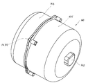
도 4는 본 발명에 따른 진공청소기의 흡음방을 도시한 분해사시도.Figure 4 is an exploded perspective view showing a sound absorption room of the vacuum cleaner according to the present invention.
도 5는 본 발명에 따른 진공청소기의 흡음방을 도시한 조립단면도.Figure 5 is an assembled cross-sectional view showing a sound absorption room of the vacuum cleaner according to the present invention.
< 도면의 주요부분에 대한 상세한 설명 ><Detailed Description of Main Parts of Drawing>
1 : 흡음방 10 : 제 1공기안내구1: Sound absorption room 10: 1st air guide
11 : 장공 12 : 안착부11: long hole 12: seating part
20 : 전방덮개 20a : 원형부20: front cover 20a: round part
20b : 사각부 23a,23b,33 : 조립홈20b:
30 : 제 2공기안내구 31 : 하부공30: second air guide 31: lower hole
32 : 보강리브 13, 33 : 끼움돌기32: reinforcing
40 : 후방덮개 41 : 배기공40: rear cover 41: exhaust hole
50 : 여과부재 51 : 배기격자50: filtering member 51: exhaust grid
100 : 진공청소기 110 : 본체100: vacuum cleaner 110: main body
130 : 구동실 131 : 모터130: drive chamber 131: motor
상기와 같은 목적을 달성하기 위한 본 발명은, 먼지봉투가 내장되는 집진실과, 모터가 내장되는 구동실을 내부격벽으로 구획한 본체를 갖추어 모터의 흡입력으로서 청소면에 대한 청소작업을 수행하는 진공청소기에 있어서, 상기 모터로 부터 빠져나오는 흡입공기를 상향유도배출하는 장공을 상부내주면에 일정간격 복수개 천공하고, 상기 모터의 축후단에 끼워진 모터장착구가 설치되는 안착부를 함몰형성한 제 1공기안내구;와, 상기 제 1공기안내구의 선단에 후단이 조립되고, 상기 모터의 모터덮개 전면에 밀착되는 모터패깅부재가 내부면에 접하는 원형부와 상기 제 1공기안내구를 수용하는 사각부를 일체로 형성한 전방덮개;와 상기 사각부후단에 조립되고, 하부측에 하부공을 복수개 천공한 제 2공기안내구;와, 상기 사각부의 후단에 수직하게 조립되는 제 2공기안내구와 더불어 선단이 수평하게 조립되고, 상기 하부공을 통해 유도되는 흡입공기를 배기하고, 이를 여과하는 여과부재가 장착되는 배기공을 후방에 갖춘 후방덮개;를 포함함을 특징으로 하는 진공청소기의 흡음방을 마련함에 의한다.The present invention for achieving the above object, a vacuum cleaner for cleaning the cleaning surface as a suction force of the motor having a dust collecting chamber in which the dust bag is built, and a main body partitioning the drive chamber in which the motor is built into the inner partition. In the first air guide port formed by drilling a plurality of holes in the upper inner circumference at a predetermined interval in the upper inner circumferential surface of the inlet air discharged from the motor, and recessed the seating portion is installed in the rear end of the motor And, the rear end is assembled to the front end of the first air guide, the motor packing member which is in close contact with the front of the motor cover of the motor integrally formed with a circular portion in contact with the inner surface and the rectangular portion for receiving the first air guide is integrally formed One front cover; and a second air guide tool which is assembled to the rear end of the blind box and drills a plurality of lower holes on the lower side; And a rear cover having a rear end having an exhaust hole equipped with a filtration member for discharging suction air guided through the lower hole, and having a front end assembled horizontally with the second air guide being lip. By providing a sound absorbing room for the vacuum cleaner.
이하, 본 발명에 따른 진공청소기의 흡음방에 대하여 첨부된 도면에 따라 상세히 설명하면 다음과 같다.Hereinafter, the sound absorbing room of the vacuum cleaner according to the present invention will be described in detail with reference to the accompanying drawings.
도 4는 본 발명에 따른 진공청소기의 흡음방을 도시한 분해사시도이고, 도 5는 본 발명에 따른 진공청소기의 흡음방을 도시한 조립단면도이다.Figure 4 is an exploded perspective view showing a sound absorbing room of the vacuum cleaner according to the present invention, Figure 5 is an assembled cross-sectional view showing a sound absorbing room of the vacuum cleaner according to the present invention.
본 발명에 따른 진공청소기의 흡음방(1)은 도 4 와 5에 도시한 바와같이, 청소작업이 가능하도록 강력한 흡입력을 발생시키는 모터(131)를 제 1,2공기안내구(10),(30)와 더불어 전,후방덮개(20),(40)내에 장착하여 구동시 발생하는 상기 모터(131)의 발생진동을 흡수하고, 상기 모터(131)로 부터 빠져나오는 흡입공기의 공기유로를 종래에 비하여 보다 연장시켜 소음을 흡수하며, 종래와 같이 조립부위에서의 틈새를 통한 공기유출을 차단하는 한편, 청정하게 여과가 이루어진 흡입공기만을 최종적으로 배기할 수 있도록 본체(110)의 구동실(130) 내부에 장착되는 것이다.As shown in FIGS. 4 and 5, the sound absorbing room 1 of the vacuum cleaner according to the present invention includes a
즉, 본 발명에 따른 흡음방(1)은 나사부재없이 간편하게 조립되는 전,후방덮개(20),(40)의 내부공간에 상기 모터(131)를 갖추는바, 이러한 모터(131)에 갖추어져 흡입공기의 배기유로를 연장시키는 제 1공기안내구(10)는 상기 집진실(120)내에서 먼지 및 이물질을 1차로 여과한 흡입공기가 흡기구부(112)와 연통되는 모터(131)내로 유입된 다음, 몸체면에 형성된 관통공(132)을 통해 배출될 때, 이를 통해 배기되는 흡입공기가 상부측으로 일단 유도배출된 후, 그 외주면을 타고 하부로 유도되어 공기유로가 연장되도록 흡입공기를 상부측으로만 유도배출하는 장공(11)을 상부내주면에 일정간격으로 복수개 천공하고, 내부면 중앙에는 상기 모터(131)의 축(132)후단에 끼워진 모터장착구(145)를 설치할 수 있는 안착부(12)를 함몰형성하는 한편, 상기 제 1공기안내구(10)의 원형 선단면에는 끼움돌기(13)를 환고리형으로 돌출형성한다. 이때, 상기 제 1공기안내구(10)의 외부면에 천공되는 복수개의 장공(11)은 흡입공기의 공기유로를 연장시킬 수 있도록 상기 모터(131) 중심을 지나는 수평선을 기준으로 상부 내주면에만 갖추어져야 한다.That is, the sound absorbing room 1 according to the present invention is provided with the
그리고, 상기 흡기구부(112)와 연통되도록 전면에 원형공(21)이 관통된 전방덮개(20)은 상기 모터(131)의 모터덮개(131a)가 위치되는 원형부(20a)와 상기 모터(131)몸체가 위치되는 사각부(20b)를 일체로 갖추어 구성되는바, 이러한 원형부(20a)의 내부면에는 모터진동을 흡수하는 모터패킹부재(141)가 접해지고, 상기 원형부(20a)의 원형후단에 형성된 조립홈(23a)으로 상기 제 1공기안내구(10)의 원형선단에 형성된 끼움돌기(13)를 압입식으로 끼워서 상기 전방덮개(20)와 제 1공기안내구(10)를 일체로 조립구성한다. 그리고, 상기 사각부(20b)에는 제 1공기안내구(10)에 의해서 외부면이 감싸지는 모터(131)의 몸체를 조립구성한다.In addition, the
또한, 상기 제 1공기안내구(10)의 유일통로인 장공(11)을 통해 유도되는 흡입공기를 하부측으로 유도하도록 상기 사각부(20b)의 후단에 수직하게 설치되는 제 2공기안내구(30)는 외주테두리에 형성된 끼움돌기(33)를 상기 사각부(20b)의 후단에 형성된 조립홈(23b)과 후술하는 후방덮개(40)의 조립홈(43)사이에 나사체결없이 조립식으로 끼움에 따라, 전방덮개(20)의 사각부(20b)후방을 밀폐하도록 수직하게 조립구성되는 것이다. 그리고, 이러한 제 2공기안내구(30)의 하부면에는 상기 장공(11)을 통해 하부측으로 유도되는 흡입공기를 상기 후방덮개(40)측으로 유도하도록 이와 연통되는 복수개의 하부공(31)을 천공하여 갖추는 한편, 인접한 하부공(31)사이에 조립시 파손을 방지하도록 보강리브(32)를 일체로 갖추어 구성한다.In addition, the second air guide (30) installed perpendicular to the rear end of the
그리고, 상기 전방덮개(20)의 사각부(20b)후단에 나사체결없이 일체로 조립구성되는 후방덮개(40)는 사각선단에 조립홈(43)을 함몰형성하여 이를 상기 사각부(20b)의 조립홈(23b)으로 일측이 끼워진 상기 제 2공기안내구(30)의 끼움돌기(33)의 타측과 조립함으로서, 상기 하부공(31)으로 부터 유도되는 흡입공기를 후방으로 유도배출하고, 후방에 관통된 배기공(41)에는 유도배기되는 흡입공기를 최종적으로 여과하는 여과부재(50)와 이를 고정하는 배기격자(51)을 갖추어 구성한다.In addition, the
상술한 바와같은 구조를 갖는 흡음방(1)을 진공청소기(100)의 구동실(130)내부에 갖추어 청소작업을 수행하는 경우, 상기 흡음방(1) 내부공간에 장착된 모터(131)의 구동으로 발생된 흡입력에 의해서 집진실(120)의 먼지봉투(125)내로 강제흡입되어 1차 여과된 흡입공기가 상기 집진실(120)과 연통되는 모터(131)내부로 유입된 다음, 몸체 외부면의 관통공(132)을 통해 배출되면, 이러한 흡입공기는 상기 모터(131)의 외부를 감싸도록 장착된 제 1공기안내구(10)의 유일통로인 상부내주면의 장공(11)측으로 자연스럽게 유도배출된 다음, 상기 제 1공기안내구(10)의 외주면과 상기 전방덮개(20)의 사각부(20b)를 밀페하도록 수직하게 설치된 제 2공기안내구(30)의 내부면을 타고 하부측으로 흐르면서 상기 제 2공기안내구(30)의 하부공(31)측으로 배기되는 것이다.When the sound absorbing room 1 having the structure as described above is provided inside the
이어서, 상기 하부공(31)으로 유도배기되는 흡입공기는 이와 연통되는 상기 후방덮개(40)측으로 다시 상향 굴곡진행되어 그 후방에 형성된 배기공(41)에 장착된 여과부재(50)를 통해 외부로 배출되는 것이다. 즉, 상기 제 1공기안내구(10)의 장공(11), 제 2공기안내구(30)의 하부공(31), 후방덮개(40)의 배기공(41) 및 여과부재(50)를 차례로 거치는 공기유로를 형성하는 흡입공기는 최종적으로 상기 여과부재(50)를 통과하면서 여과가 이루어진 다음, 청정한 배기공기상태로 진공청소기(100) 밖으로 배기되는 것이다.Subsequently, the suction air guided to the
그리고, 상기 모터(131)로 부터 배출되어 후방덮개(40)를 거쳐 외부로 배기되는 흡입공기에 대한 흡음효율을 높여 진공청소기(100)의 성능을 향상시킬 수 있도록, 공기유로를 형성하는 흡입공기와 접하는 제 1,2공기안내구(10),(30), 전방덮개(20)의 사각부(20b) 및 후방덮개(40)의 내부면에 흡음재를 부착하여도 바람직하다.In addition, the suction air for forming an air flow path to improve the performance of the
따라서, 본 발명에 따른 진공청소기의 흡음방(1)에 의하면, 제 1공기안내구(10)를 갖는 모터(131)가 내장되는 전방덮개(20)와 후방덮개(40)를 제 2공기안내구(30)와 더불어 나사체결없이 간편하게 조립할 수 있고, 그 조립부위에서의 밀폐가 양호하여 종래와 같이, 틈새를 통한 흡입공기의 외부유출을 방지하고, 모터(131)로 부터 시작되는 배기유로를 제 1,2공기안내구(10),(30)에 의해서 종래에 비하여 보다 길게 연장함으로서, 소음, 차음효율을 현저히 향상시켜 진공청소기(100)의 성능을 향상시킴은 물론, 인체에 무해한 청정 배기공기만을 외부로 배출할 수 있는 고청정 진공청소기를 제조할 수 있는 효과가 얻어진다.Therefore, according to the sound absorbing room 1 of the vacuum cleaner according to the present invention, the
Claims (6)
Priority Applications (6)
| Application Number | Priority Date | Filing Date | Title |
|---|---|---|---|
| KR1019970055332A KR100231437B1 (en) | 1997-10-27 | 1997-10-27 | MCS(Muffler Chamber System) of Vacuum Cleaner |
| JP12726898A JP3654330B2 (en) | 1997-10-27 | 1998-05-11 | Low noise vacuum cleaner |
| DE69816933T DE69816933T2 (en) | 1997-10-27 | 1998-05-11 | Low-noise vacuum cleaner |
| ES98108525T ES2203853T3 (en) | 1997-10-27 | 1998-05-11 | SILENT ASPIRATOR. |
| EP98108525A EP0910980B1 (en) | 1997-10-27 | 1998-05-11 | Low noise vacuum cleaner |
| US09/080,246 US6070289A (en) | 1997-10-27 | 1998-05-18 | Low noise vacuum cleaner |
Applications Claiming Priority (1)
| Application Number | Priority Date | Filing Date | Title |
|---|---|---|---|
| KR1019970055332A KR100231437B1 (en) | 1997-10-27 | 1997-10-27 | MCS(Muffler Chamber System) of Vacuum Cleaner |
Publications (2)
| Publication Number | Publication Date |
|---|---|
| KR19990033890A KR19990033890A (en) | 1999-05-15 |
| KR100231437B1 true KR100231437B1 (en) | 1999-11-15 |
Family
ID=19523505
Family Applications (1)
| Application Number | Title | Priority Date | Filing Date |
|---|---|---|---|
| KR1019970055332A Expired - Fee Related KR100231437B1 (en) | 1997-10-27 | 1997-10-27 | MCS(Muffler Chamber System) of Vacuum Cleaner |
Country Status (1)
| Country | Link |
|---|---|
| KR (1) | KR100231437B1 (en) |
Cited By (1)
| Publication number | Priority date | Publication date | Assignee | Title |
|---|---|---|---|---|
| KR101044829B1 (en) * | 2003-05-07 | 2011-06-28 | 엘지전자 주식회사 | Motor Chamber of Vacuum Cleaner |
Families Citing this family (2)
| Publication number | Priority date | Publication date | Assignee | Title |
|---|---|---|---|---|
| KR100454473B1 (en) * | 2002-01-17 | 2004-10-28 | 이병호 | A air suction cleaner |
| KR100474345B1 (en) * | 2002-10-11 | 2005-03-10 | 엘지전자 주식회사 | Motor supporting devise for vacuum-cleaner |
-
1997
- 1997-10-27 KR KR1019970055332A patent/KR100231437B1/en not_active Expired - Fee Related
Cited By (1)
| Publication number | Priority date | Publication date | Assignee | Title |
|---|---|---|---|---|
| KR101044829B1 (en) * | 2003-05-07 | 2011-06-28 | 엘지전자 주식회사 | Motor Chamber of Vacuum Cleaner |
Also Published As
| Publication number | Publication date |
|---|---|
| KR19990033890A (en) | 1999-05-15 |
Similar Documents
| Publication | Publication Date | Title |
|---|---|---|
| US7475449B2 (en) | Vacuum cleaner | |
| EP0910980B1 (en) | Low noise vacuum cleaner | |
| JPH1132947A (en) | Noise absorbing device of vacuum cleaner | |
| KR102492164B1 (en) | Vacuum cleaner | |
| KR19990026206A (en) | Air flow structure of vacuum cleaner | |
| US11452411B2 (en) | Robot cleaner | |
| KR100231437B1 (en) | MCS(Muffler Chamber System) of Vacuum Cleaner | |
| KR100231435B1 (en) | MCS(Muffler Chamber System) of Vacuum Cleaner | |
| KR100545269B1 (en) | Noise attenuation structure of motor for vacuum cleaner | |
| KR100231436B1 (en) | MCS(Muffler Chamber System) of Vacuum Cleaner | |
| AU2004202983B2 (en) | Vacuum Cleaner | |
| KR100213365B1 (en) | Noise reduction structure of vacuum cleaner | |
| KR0148955B1 (en) | Muffler chamber system of vacuum cleaner | |
| KR200205691Y1 (en) | Noise reduction structure of the vacuum cleaner sound absorption case | |
| JP2005218539A (en) | Electric blower unit and vacuum cleaner incorporating the same | |
| KR0133743B1 (en) | Sound-absorbing room of vacuum cleaner with rear sound insulation cover | |
| KR19980017825A (en) | Motor mounting structure of vacuum cleaner | |
| KR100270800B1 (en) | A noise decreasing device of a vacuum cleaner | |
| KR0136318B1 (en) | Mufler chamber system of a vacuum cleaner | |
| KR0123729Y1 (en) | Structure of muffler chamber system in vacuum cleaner | |
| KR19990023962U (en) | Sound-absorbing exhaust structure of vacuum cleaner | |
| KR200143211Y1 (en) | Vibration buffer fixing structure of vacuum cleaner motor | |
| KR20030000586A (en) | Vacuum cleaner | |
| KR20000004575A (en) | Integrated typed sound absorbing device of vacuum cleaner | |
| KR0148942B1 (en) | Sound absorbing structure with long flow path |
Legal Events
| Date | Code | Title | Description |
|---|---|---|---|
| A201 | Request for examination | ||
| PA0109 | Patent application |
St.27 status event code: A-0-1-A10-A12-nap-PA0109 |
|
| PA0201 | Request for examination |
St.27 status event code: A-1-2-D10-D11-exm-PA0201 |
|
| R17-X000 | Change to representative recorded |
St.27 status event code: A-3-3-R10-R17-oth-X000 |
|
| PG1501 | Laying open of application |
St.27 status event code: A-1-1-Q10-Q12-nap-PG1501 |
|
| E902 | Notification of reason for refusal | ||
| PE0902 | Notice of grounds for rejection |
St.27 status event code: A-1-2-D10-D21-exm-PE0902 |
|
| P11-X000 | Amendment of application requested |
St.27 status event code: A-2-2-P10-P11-nap-X000 |
|
| P13-X000 | Application amended |
St.27 status event code: A-2-2-P10-P13-nap-X000 |
|
| E701 | Decision to grant or registration of patent right | ||
| PE0701 | Decision of registration |
St.27 status event code: A-1-2-D10-D22-exm-PE0701 |
|
| GRNT | Written decision to grant | ||
| PR0701 | Registration of establishment |
St.27 status event code: A-2-4-F10-F11-exm-PR0701 |
|
| PR1002 | Payment of registration fee |
St.27 status event code: A-2-2-U10-U11-oth-PR1002 Fee payment year number: 1 |
|
| PG1601 | Publication of registration |
St.27 status event code: A-4-4-Q10-Q13-nap-PG1601 |
|
| R18-X000 | Changes to party contact information recorded |
St.27 status event code: A-5-5-R10-R18-oth-X000 |
|
| R18-X000 | Changes to party contact information recorded |
St.27 status event code: A-5-5-R10-R18-oth-X000 |
|
| PR1001 | Payment of annual fee |
St.27 status event code: A-4-4-U10-U11-oth-PR1001 Fee payment year number: 4 |
|
| PN2301 | Change of applicant |
St.27 status event code: A-5-5-R10-R11-asn-PN2301 |
|
| PN2301 | Change of applicant |
St.27 status event code: A-5-5-R10-R11-asn-PN2301 |
|
| PN2301 | Change of applicant |
St.27 status event code: A-5-5-R10-R14-asn-PN2301 |
|
| PR1001 | Payment of annual fee |
St.27 status event code: A-4-4-U10-U11-oth-PR1001 Fee payment year number: 5 |
|
| PR1001 | Payment of annual fee |
St.27 status event code: A-4-4-U10-U11-oth-PR1001 Fee payment year number: 6 |
|
| PR1001 | Payment of annual fee |
St.27 status event code: A-4-4-U10-U11-oth-PR1001 Fee payment year number: 7 |
|
| PR1001 | Payment of annual fee |
St.27 status event code: A-4-4-U10-U11-oth-PR1001 Fee payment year number: 8 |
|
| PR1001 | Payment of annual fee |
St.27 status event code: A-4-4-U10-U11-oth-PR1001 Fee payment year number: 9 |
|
| FPAY | Annual fee payment |
Payment date: 20080801 Year of fee payment: 10 |
|
| PR1001 | Payment of annual fee |
St.27 status event code: A-4-4-U10-U11-oth-PR1001 Fee payment year number: 10 |
|
| LAPS | Lapse due to unpaid annual fee | ||
| PC1903 | Unpaid annual fee |
St.27 status event code: A-4-4-U10-U13-oth-PC1903 Not in force date: 20090831 Payment event data comment text: Termination Category : DEFAULT_OF_REGISTRATION_FEE |
|
| PC1903 | Unpaid annual fee |
St.27 status event code: N-4-6-H10-H13-oth-PC1903 Ip right cessation event data comment text: Termination Category : DEFAULT_OF_REGISTRATION_FEE Not in force date: 20090831 |
|
| P22-X000 | Classification modified |
St.27 status event code: A-4-4-P10-P22-nap-X000 |
|
| P22-X000 | Classification modified |
St.27 status event code: A-4-4-P10-P22-nap-X000 |