JPWO2020100528A1 - Solar cell module and its manufacturing method - Google Patents
Solar cell module and its manufacturing method Download PDFInfo
- Publication number
- JPWO2020100528A1 JPWO2020100528A1 JP2020556736A JP2020556736A JPWO2020100528A1 JP WO2020100528 A1 JPWO2020100528 A1 JP WO2020100528A1 JP 2020556736 A JP2020556736 A JP 2020556736A JP 2020556736 A JP2020556736 A JP 2020556736A JP WO2020100528 A1 JPWO2020100528 A1 JP WO2020100528A1
- Authority
- JP
- Japan
- Prior art keywords
- solar cell
- light receiving
- receiving side
- wiring
- electrically connected
- Prior art date
- Legal status (The legal status is an assumption and is not a legal conclusion. Google has not performed a legal analysis and makes no representation as to the accuracy of the status listed.)
- Granted
Links
Images


Classifications
-
- H—ELECTRICITY
- H10—SEMICONDUCTOR DEVICES; ELECTRIC SOLID-STATE DEVICES NOT OTHERWISE PROVIDED FOR
- H10F—INORGANIC SEMICONDUCTOR DEVICES SENSITIVE TO INFRARED RADIATION, LIGHT, ELECTROMAGNETIC RADIATION OF SHORTER WAVELENGTH OR CORPUSCULAR RADIATION
- H10F19/00—Integrated devices, or assemblies of multiple devices, comprising at least one photovoltaic cell covered by group H10F10/00, e.g. photovoltaic modules
- H10F19/90—Structures for connecting between photovoltaic cells, e.g. interconnections or insulating spacers
-
- Y—GENERAL TAGGING OF NEW TECHNOLOGICAL DEVELOPMENTS; GENERAL TAGGING OF CROSS-SECTIONAL TECHNOLOGIES SPANNING OVER SEVERAL SECTIONS OF THE IPC; TECHNICAL SUBJECTS COVERED BY FORMER USPC CROSS-REFERENCE ART COLLECTIONS [XRACs] AND DIGESTS
- Y02—TECHNOLOGIES OR APPLICATIONS FOR MITIGATION OR ADAPTATION AGAINST CLIMATE CHANGE
- Y02E—REDUCTION OF GREENHOUSE GAS [GHG] EMISSIONS, RELATED TO ENERGY GENERATION, TRANSMISSION OR DISTRIBUTION
- Y02E10/00—Energy generation through renewable energy sources
- Y02E10/50—Photovoltaic [PV] energy
Landscapes
- Photovoltaic Devices (AREA)
Abstract
複数の裏面接合型の太陽電池セル(11)を有する太陽電池ストリング(10)が封止材層に埋め込まれ、太陽電池ストリング(10)の末端の太陽電池セル(11)のストリング端側の端辺部にタブ配線(13)が電気的に接続された太陽電池モジュールの製造方法である。末端の太陽電池セル(11)とタブ配線(13)との電気的接続を、封止材層における太陽電池ストリングよりも受光側部分となる予定の受光側封止材(21’)上で加熱して行う。A solar cell string (10) having a plurality of back-bonded solar cells (11) is embedded in the encapsulant layer, and the end of the solar cell (11) at the end of the solar cell (10). This is a method for manufacturing a solar cell module in which a tab wiring (13) is electrically connected to a side portion. The electrical connection between the terminal solar cell (11) and the tabbed wiring (13) is heated on the light receiving side encapsulant (21'), which will be the light receiving side portion of the encapsulant layer from the solar cell string. And do it.
Description
本発明は、太陽電池モジュール及びその製造方法に関する。 The present invention relates to a solar cell module and a method for manufacturing the same.
裏面接合型(バックコンタクト型)の太陽電池セルは、p型及びn型の両電極が裏面に配置されている。そのため、これを用いた太陽電池モジュールでは、電極が受光側に露出しない意匠性の優れたものとなる。例えば、特許文献1には、そのような裏面接合型の太陽電池セルを用いた太陽電池モジュールが開示されている。 In the back contact type solar cell, both p-type and n-type electrodes are arranged on the back surface. Therefore, in the solar cell module using this, the electrode is not exposed to the light receiving side, and the design is excellent. For example, Patent Document 1 discloses a solar cell module using such a back-bonded solar cell.
本発明は、直列に配置され且つ電気的に接続された複数の裏面接合型の太陽電池セルを有する太陽電池ストリングと、前記太陽電池ストリングが埋め込まれた封止材層とを備え、前記太陽電池ストリングの末端の太陽電池セルのストリング端側の端辺部にタブ配線が電気的に接続された太陽電池モジュールの製造方法であって、前記末端の太陽電池セルと前記タブ配線との電気的接続を、前記封止材層における前記太陽電池ストリングよりも受光側部分となる予定の受光側封止材上で加熱して行うものである。 The present invention comprises a solar cell string having a plurality of back-bonded solar cell cells arranged in series and electrically connected, and a sealing material layer in which the solar cell string is embedded. It is a method of manufacturing a solar cell module in which a tab wiring is electrically connected to an end portion of a solar cell at the end of a string on the string end side, and is an electrical connection between the solar cell at the end and the tab wiring. Is heated on the light receiving side sealing material to be the light receiving side portion of the sealing material layer with respect to the solar cell string.
本発明は、並列に配置され、各々、直列に配置され且つ電気的に接続された複数の裏面接合型の太陽電池セルを有する一対の太陽電池ストリングと、前記一対の太陽電池ストリングが埋め込まれた封止材層とを備え、前記一対の太陽電池ストリングの末端の太陽電池セルに電気的に接続されたタブ配線間が渡り配線で電気的に接続された太陽電池モジュールであって、前記タブ配線及び前記渡り配線は、前者が裏側及び後者が受光側にそれぞれ配置されて重なっている。 In the present invention, a pair of solar cell strings arranged in parallel, each having a plurality of back-joined solar cell cells arranged in series and electrically connected, and the pair of solar cell strings are embedded. A solar cell module comprising a sealing material layer and electrically connected to a solar cell at the end of the pair of solar cell strings by a cross wire, wherein the tab wiring is electrically connected. In the crossover wiring, the former is arranged on the back side and the latter is arranged on the light receiving side and overlaps.
以下、実施形態に係る太陽電池モジュールの製造方法について図面に基づいて詳細に説明する。なお、本出願では、太陽電池モジュール及び太陽電池セルにおける太陽光を受光する側を「受光側」及びその反対側を「裏側」という。また、受光側の面を「受光面」及び裏側の面を「裏面」という。 Hereinafter, the method for manufacturing the solar cell module according to the embodiment will be described in detail with reference to the drawings. In this application, the side of the solar cell module and the solar cell that receives sunlight is referred to as the "light receiving side" and the opposite side thereof is referred to as the "back side". Further, the surface on the light receiving side is referred to as a "light receiving surface" and the surface on the back side is referred to as a "back surface".
(実施形態1)
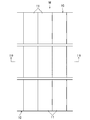
図1A及びBは、実施形態1に係る方法で製造する太陽電池モジュールMを示す。(Embodiment 1)
1A and 1B show a solar cell module M manufactured by the method according to the first embodiment.
この太陽電池モジュールMは、間隔をあけて並列に配置された複数の太陽電池ストリング10と、それらの太陽電池ストリング10が埋め込まれた封止材層20と、封止材層20の受光側及び裏側にそれぞれ積層された受光側保護部材30及び裏側保護部材40とを備える。複数の太陽電池ストリング10のそれぞれは、直列に配置され且つ電気的に接続された複数の裏面接合型の太陽電池セル11を有する。また、それらの複数の太陽電池セル11はシングリング接続されている。
The solar cell module M includes a plurality of
図2は、裏面接合型の太陽電池セル11(以下、単に「太陽電池セル11」ともいう。)の一例を示す。この太陽電池セル11は、長方形状の半導体基板であるセル本体110の裏面に、p型電極及びn型電極のうちの一方の第1電極111と他方の第2電極112とが配置されている。第1電極111及び第2電極112は、各々が櫛形状で且つ互いに櫛歯が噛み合うようにパターニングされている。第1電極111は、複数本の第1電極フィンガー部分111aと、1本の第1電極バスバー部分111bとを有する。複数本の第1電極フィンガー部分111aは、各々がセル本体110の短辺方向に延びるとともに、長辺方向に間隔をあけて並行に延びるように配置されている。第1電極バスバー部分111bは、複数本の第1電極フィンガー部分111aの一端を連結してセル本体110の一方の長辺に沿って長辺方向に延びるように配置されている。第2電極112は、複数本の第2電極フィンガー部分112aと、1本の第2電極バスバー部分112bとを有する。複数本の第2電極フィンガー部分112aは、各々が第1電極フィンガー部分111a間にセル本体110の短辺方向に延びるとともに、長辺方向に間隔をあけて並行に延びるように配置されている。第2電極バスバー部分112bは、複数本の第2電極フィンガー部分112aの一端を連結してセル本体110の他方の長辺に沿って長辺方向に延びるように配置されている。なお、太陽電池セル11の形状や配線パターン等は、これらに限定されるものではない。
FIG. 2 shows an example of a back surface bonded type solar cell 11 (hereinafter, also simply referred to as “
ここで、本出願における「シングリング接続」とは、図3A及びBに示すように、太陽電池ストリング10の複数の太陽電池セル11における任意の連続して配置された第1太陽電池セル11−1、第2太陽電池セル11−2、及び第3太陽電池セル11−3において、図3Aに示すような、第2太陽電池セル11−2の一端部11aが第1太陽電池セル11−1の他端部11bの受光側に配置されて重なっているとともに、第2太陽電池セル11−2の他端部11bが第3太陽電池セル11−3の一端部11aの裏側に配置されて重なっているセル接続構造、又は、図3Bに示すような、第2太陽電池セル11−2の一端部11aが第1太陽電池セル11−1の他端部11bの裏側に配置されて重なっているとともに、第2太陽電池セル11−2の他端部11bが第3太陽電池セル11−3の一端部11aの受光側に配置されて重なっているセル接続構造をいう。
Here, as shown in FIGS. 3A and 3B, the "singling connection" in the present application means an arbitrary continuously arranged first solar cell 11-in a plurality of
封止材層20は、その複数の太陽電池ストリング10よりも受光側の受光側部分21と、裏側の裏側部分22とを有する樹脂層である。封止材層20は、受光側部分21となる予定の受光側封止材と、裏側部分22となる予定の裏側封止材とが溶融一体化したものである。これらの受光側封止材及び裏側封止材の形成材料としては、例えば、エチレン酢酸ビニル共重合体樹脂(EVA)、エチレンエチルアクリレート共重合体樹脂(EEA)、エチレンα−オレフィン共重合体樹脂、ポリビニルブチラール樹脂(PVB)、オレフィン系樹脂、アイオノマー系樹脂などを主成分とする熱可塑性樹脂製の板材;アクリル樹脂、エポキシ樹脂、フェノール樹脂などを主成分とするもの等が挙げられる。受光側封止材及び裏側封止材は、形成材料が同一であっても、異なっていても、どちらでもよい。
The
受光側保護部材30としては、例えば、ガラス、アクリル樹脂、ポリカーボネート樹脂等の透明な板材が挙げられる。裏側保護部材40としては、例えば、ポリエチレンテレフタレート樹脂(PET)、ポリエチレン(PE)などのオレフィン系樹脂、含フッ素樹脂、または含シリコーン樹脂等を含むフィルムを積層させた積層体(板材)が挙げられる。
Examples of the light receiving side
実施形態1に係る太陽電池モジュールMの製造方法では、まず、複数の太陽電池セル11をシングリング接続した太陽電池ストリング10を複数作製する。
In the method for manufacturing the solar cell module M according to the first embodiment, first, a plurality of solar cell strings 10 in which a plurality of
このとき、図4A及びBに示すように、一対の太陽電池セル11について、それらのうちの一方(図4Aの正面視における右側)の一端部11aと他方(図4Aの正面視における左側)の他端部11bとを、前者が受光側及び後者が裏側に配置されるように重ね、その後、一方の太陽電池セル11の第1電極111の第1電極バスバー部分111bと、他方の太陽電池セル11の第2電極112の第2電極バスバー部分112bとを電気的に接続する。なお、一対の太陽電池セル11について、それらのうちの一方の一端部11aと他方の他端部11bとを、前者が裏側及び後者が受光側に配置されるように重ねてもよい。
At this time, as shown in FIGS. 4A and 4B, with respect to the pair of
この第1電極バスバー部分111bと第2電極バスバー部分112bとの電気的接続は、導電性の電極接続部材12を用い、第1電極バスバー部分111bと電極接続部材12とを半田や導電性接着剤を用いて電気的に接続するとともに、第2電極バスバー部分112bと電極接続部材12とを同様に電気的に接続すればよい。電極接続部材12は、複数箇所に配置することが好ましい。
A conductive
このような一対の太陽電池セル11間の電気的接続を繰り返し行うことにより、図5A及びBに示すように、複数の太陽電池セル11がシングリング接続されるとともに、それらの複数の太陽電池セル11が直列に配置され且つ電気的に接続された太陽電池ストリング10が得られる。
By repeatedly making such an electrical connection between the pair of
太陽電池ストリング10を作製した後、次いで、図6A及びBに示すように、受光側保護部材30及び受光側封止材21’を順に積層し、その上に、複数の太陽電池ストリング10を、それぞれ受光面を受光側封止材21’に対向させるとともに、間隔をあけて並列に配置する。
After producing the
このとき、並列に配置する複数の太陽電池ストリング10について、同一側の末端の太陽電池セル11に関し、太陽電池ストリング10の配置方向に、ストリング端側の端辺部に第1電極バスバー部分111bが配置された太陽電池セル11と、ストリング端側の端辺部に第2電極バスバー部分112bが配置された太陽電池セル11とが交互に配置されるようにする。
At this time, with respect to the plurality of solar cell strings 10 arranged in parallel, the first electrode
次いで、受光側封止材21’上に並列に配置した複数の太陽電池ストリング10のそれぞれについて、図7A及びBに示すように、両末端のそれぞれの太陽電池セル11における隣接セルが存在しないストリング端側の端辺部の側方に引き出すようにタブ配線13を配置し、そのストリング端側の端辺部に配置された長辺方向に延びる第1電極バスバー部分111b又は第2電極バスバー部分112bと、そのタブ配線13とを電気的に接続する。タブ配線13は、複数箇所に配置することが好ましい。
Next, for each of the plurality of solar cell strings 10 arranged in parallel on the light receiving side sealing material 21', as shown in FIGS. 7A and 7B, strings in which adjacent cells in the respective
このとき、末端の太陽電池セル11の第1電極バスバー部分111b又は第2電極バスバー部分112bとタブ配線13との電気的接続を、受光側封止材21’上で熱源50を接触させて加熱することにより行う。また、熱源50により末端の太陽電池セル11を受光側封止材21’に押し付けて面接触させる。この電気的接続を受光側封止材21’上で加熱して行うと、その熱が末端の太陽電池セル11に伝導し、それにより受光側封止材21’が軟化乃至溶融して一端側の末端の太陽電池セル11に融着する。受光側封止材21’の末端の太陽電池セル11への融着状態を容易に調整する観点からは、受光側封止材21’は、再加熱により可塑化する熱可塑性樹脂を含むことが好ましい。
At this time, the electrical connection between the first electrode
ここで、本出願における「受光側封止材21’上で行う電気的接続」とは、受光側封止材21’の対向位置で行う電気的接続を意味する。したがって、例えば受光側封止材21’が立てて配置され、受光側封止材21’の表面が鉛直面である場合も、受光側封止材21’の対向位置で行う電気的接続は、「受光側封止材21’上で行う電気的接続」に含まれる。 Here, the "electrical connection made on the light receiving side sealing material 21'" in the present application means an electrical connection made at a position facing the light receiving side sealing material 21'. Therefore, for example, even when the light-receiving side encapsulant 21'is arranged upright and the surface of the light-receiving side encapsulant 21'is vertically facing, the electrical connection made at the position facing the light-receiving side encapsulant 21'is It is included in "electrical connection made on the light receiving side sealing material 21'".
加熱して行う電気的接続手段としては、例えば、導電性接着剤を用いて行う手段、半田付けによる手段が挙げられる。これらのうち、受光側封止材21’の過剰な溶融及び局所的な硬化により受光側の意匠が損なわれるのを抑制する観点から、比較的低温での加熱で電気的接続する導電性接着剤を用いて行う手段が好ましい。具体的には、例えば、図8に示すように、末端の太陽電池セル11の第1電極バスバー部分111b又は第2電極バスバー部分112b上にペースト状の導電性接着剤14を適量付着させ、更にその上にタブ配線13を配置した後、タブ配線13上に熱源50を接触させて加熱することにより導電性接着剤14を硬化させる。
Examples of the electrical connection means performed by heating include a means using a conductive adhesive and a means by soldering. Of these, a conductive adhesive that is electrically connected by heating at a relatively low temperature from the viewpoint of suppressing damage to the design on the light receiving side due to excessive melting and local curing of the light receiving side encapsulant 21'. Is preferred. Specifically, for example, as shown in FIG. 8, an appropriate amount of a paste-like conductive adhesive 14 is adhered on the first electrode
導電性接着剤14は、未硬化のペースト状の熱硬化性樹脂と、それに分散した金属の導電性粒子とを含む。熱硬化性樹脂としては、例えば、エポキシ樹脂、イミド樹脂、フェノール樹脂等が挙げられる。導電性粒子の金属としては、例えば、銀、スズ、ニッケル、銅、若しくは亜鉛等、またはそれらの合金が挙げられる。 The conductive adhesive 14 contains an uncured paste-like thermosetting resin and metallic conductive particles dispersed therein. Examples of the thermosetting resin include epoxy resin, imide resin, phenol resin and the like. Examples of the metal of the conductive particles include silver, tin, nickel, copper, zinc and the like, or alloys thereof.
この末端の太陽電池セル11とタブ配線13との電気的接続における加熱温度は、受光側封止材21’を軟化乃至溶融させて末端の太陽電池セル11への融着を促進する観点から、好ましくは受光側封止材21’の融点よりも50℃高い温度以上である。また、その加熱温度は、受光側封止材21’の過剰な溶融及び局所的な硬化により受光側の意匠が損なわれるのを抑制する観点から、好ましくは受光側封止材21’の融点よりも250℃高い温度以下である。受光側封止材21’の融点は、例えば、エチレン酢酸ビニル共重合体樹脂(EVA)では60〜80℃、オレフィン系樹脂では60〜120℃、アイオノマー系樹脂では90〜100℃である。この受光側封止材21’の融点は、JIS K7121:2012に基づいて示差走査熱量測定(DSC)により測定される融解ピーク温度である。
The heating temperature in the electrical connection between the terminal
次いで、受光側封止材21’上に並列に配置した複数の太陽電池ストリング10のうちの第1及び第2の相互に隣接する一対の太陽電池ストリング10について、図9A及びBに示すように、第1の太陽電池ストリング10の一端側の第1の末端の太陽電池セル11から延びる第1のタブ配線13と、第2の太陽電池ストリング10の一端側の第2の末端の太陽電池セル11から延びる第2のタブ配線13との間を渡すように渡り配線15を配置する。第1のタブ配線13と渡り配線15とを電気的に接続するとともに、第2のタブ配線13と渡り配線15とを電気的に接続することにより、第1及び第2の末端の太陽電池セル11間を電気的に接続する。この電気的接続も、半田や導電性接着剤を用いて加熱して行うことが好ましい。
Next, as shown in FIGS. 9A and 9B, the first and second pair of solar cell strings 10 adjacent to each other among the plurality of solar cell strings 10 arranged in parallel on the light receiving side sealing material 21' , The
このとき、これらの第1及び第2のタブ配線13と渡り配線15とを加熱により電気的に接続する場合、第1及び第2の太陽電池ストリング10の受光側封止材21’への融着を補助する観点からは、第1及び第2のタブ配線13と渡り配線15とのうちの少なくとも一方を受光側封止材21’に接触させて配置することにより受光側封止材21’に融着させることが好ましく、図10に示すように、面積の大きい渡り配線15を受光側封止材21’に接触させて配置することがより好ましい。また、それらの接続作業性が優れる観点からは、図10に示すように、第1のタブ配線13及び第2のタブ配線13を渡り配線15上、つまり、受光側封止材21’側とは反対側に重ねて配置することが好ましい。この場合、接続後の第1及び第2のタブ配線13と渡り配線15とは、前者が裏側及び後者が受光側にそれぞれ配置されて重なる。
At this time, when the first and
なお、渡り配線15の受光側封止材21’上への配置は、第1及び第2の太陽電池ストリング10の受光側封止材21’上への配置の前、又は、その後で且つ第1及び第2のタブ配線13の配置の前に行ってもよい。また、第1及び第2のタブ配線13と渡り配線15との電気的接続は、末端の太陽電池セル11とタブ配線13との電気的接続の前に行ってもよく、さらに、その前に受光側封止材21’上以外で行ってもよい。
The arrangement of the
次いで、図11A及びBに示すように、並列に配置された複数の太陽電池ストリング10のうちの相互に隣接する第2及び第3の一対の太陽電池ストリング10について、同様に、第2の太陽電池ストリング10の他端側の第2の末端の太陽電池セル11から延びる第2のタブ配線13と、第3の太陽電池ストリング10の他端側の第3の末端の太陽電池セル11から延びる第3のタブ配線13との間を渡すように渡り配線15を配置する。第2のタブ配線13と渡り配線15とを電気的に接続するとともに、第3のタブ配線13と渡り配線15とを電気的に接続する。
Then, as shown in FIGS. 11A and 11B, similarly, for the second and third pair of solar cell strings 10 adjacent to each other among the plurality of solar cell strings 10 arranged in parallel, the second sun A
続いて、同様に複数の太陽電池ストリング10のうちの相互に隣接する一対の太陽電池ストリング10間を電気的に接続することにより、図12に示すように、これらの複数の太陽電池ストリング10が全体として電気的に直列に接続される。また、電気的に直列に接続された両端の太陽電池ストリング10のそれぞれから延びるタブ配線13には、他のタブ配線13と渡り配線15との電気的接続方法と同様にして、引き出し配線16を電気的に接続する。このとき、それらの接続作業性が優れる観点からは、引き出し配線16の受光側封止材21’側とは反対側にタブ配線13を重ねて配置することが好ましい。
Subsequently, similarly, by electrically connecting a pair of solar cell strings 10 adjacent to each other among the plurality of solar cell strings 10, as shown in FIG. 12, these plurality of solar cell strings 10 are connected. As a whole, they are electrically connected in series. Further, the
そして、図13に示すように、太陽電池ストリング10上に、裏側封止材22’及び裏側保護部材40を順に積層し、太陽電池ストリング10を受光側封止材21’と裏側封止材22’とで挟み、それらの積層体を、真空排気を行うラミネータ等を用いて、所定の温度及び圧力で加熱及び加圧する。
Then, as shown in FIG. 13, the back side sealing material 22'and the back side
このとき、受光側封止材21’及び裏側封止材22’が溶融一体化して並列に配置された状態の複数の太陽電池ストリング10を埋め込んだ封止材層20となるとともに、それが受光側保護部材30及び裏側保護部材40と一体化して太陽電池モジュールMが製造される。また、製造される太陽電池モジュールMは、図10に示すように、渡り配線15上に末端の太陽電池セル11から延びるタブ配線13を重ねて配置して電気的に接続した場合には、タブ配線13及び渡り配線15が、前者が裏側及び後者が受光側にそれぞれ配置されて重なったものとなる。
At this time, the light receiving side sealing material 21'and the back side sealing material 22' are melted and integrated to form a sealing
ところで、裏面接合型の太陽電池セルには受光側に凸の反りがある場合が多く、それを直列に配置し且つ電気的に接続した太陽電池ストリングでは、その反りが保持される。しかも、太陽電池セルがシングリング接続した構造では、反りが累積されて特に顕著となる。そして、太陽電池モジュールを製造するときには、そのような太陽電池ストリングを、上下から樹脂製の封止材で挟んで加圧することにより封止するが、その際、反りを伸ばす方向に大きな変形が加えられるため、太陽電池ストリング内の太陽電池セルにクラックが生じる虞がある。これに対し、上記のような実施形態1に係る太陽電池モジュールMの製造方法では、受光側封止材21’上に配置した複数の太陽電池ストリング10のそれぞれについて、末端の太陽電池セル11とタブ配線13とを電気的に接続するとき、その電気的接続を受光側封止材21’上で加熱して行う。このとき、その熱が末端の太陽電池セル11に伝導し、受光側封止材21’が軟化乃至溶融して末端の太陽電池セル11に融着する。末端の太陽電池セル11が受光側封止材21’に融着すると、太陽電池ストリング10は、図14Aに示すように、受光側封止材21’上で反りを有した状態から、図14Bに示すように、受光側封止材21’上で伸ばされた状態となる。これにより、太陽電池ストリング10の反りが緩和され、この後、太陽電池ストリング10を受光側封止材21’と裏側封止材22’とで挟んで加圧するとき、太陽電池ストリング10には、反りを伸ばす方向に大きな変形が加わることがない。その結果、太陽電池モジュールMの製造時において、太陽電池ストリング10内の裏面接合型の太陽電池セル11におけるクラックの発生が抑制されることとなり、太陽電池モジュールMの生産性及び歩留まりが高められる。
By the way, the back surface bonded type solar cell often has a convex warp on the light receiving side, and the warp is maintained in the solar cell string in which the warp is arranged in series and electrically connected. Moreover, in the structure in which the solar cells are connected in a single ring, the warpage is accumulated and becomes particularly remarkable. Then, when manufacturing a solar cell module, such a solar cell string is sealed by sandwiching it between upper and lower resin sealing materials and pressurizing it, but at that time, a large deformation is added in the direction of extending the warp. Therefore, there is a possibility that the solar cell in the solar cell string may be cracked. On the other hand, in the method for manufacturing the solar cell module M according to the first embodiment as described above, each of the plurality of solar cell strings 10 arranged on the light receiving side sealing material 21'has a
(実施形態2)
実施形態2に係る太陽電池モジュールMの製造方法では、製造する太陽電池モジュールMが備える複数の太陽電池ストリング10のそれぞれが有する複数の太陽電池セル11のうち、いずれの相互に隣接する予定の一対の太陽電池セル11についても、図15に示すように、一対の太陽電池セル11のうちの一端部11aが受光側に配置された一方の太陽電池セル11(図15における右側)の第1電極バスバー部分111bと、他端部11bが裏側に配置された他方の太陽電池セル11(図15における左側)の第2電極バスバー部分112bとの間に渡すように電極接続部材12を配置し、第1電極バスバー部分111bと電極接続部材12との電気的接続、及び第2電極バスバー部分112bと電極接続部材12との電気的接続のそれぞれを受光側封止材21’上で熱源50を接触させて加熱することにより行い、それらの相互に隣接する予定の一対の太陽電池セル11間を電気的に接続する。つまり、受光側封止材21’上で、並列に配置された太陽電池ストリング10を作製する。なお、実施形態1と同一名称の部分は、実施形態1と同一符号を用いて示す。また、製造する太陽電池モジュールMの構成は、実施形態1と同一である。(Embodiment 2)
In the method for manufacturing the solar cell module M according to the second embodiment, any of the plurality of
このとき、まず、一方の太陽電池セル11の第1電極バスバー部分111bと電極接続部材12との電気的接続を受光側封止材21’上で熱源50を接触させて加熱することにより行う。また、熱源50により一方の太陽電池セル11を受光側封止材21’に押し付けて面接触させる。この電気的接続を受光側封止材21’上で加熱して行うと、その熱が一方の太陽電池セル11に伝導し、それにより受光側封止材21’が軟化乃至溶融して一方の太陽電池セル11に融着する。
At this time, first, the electrical connection between the first electrode
次いで、他方の太陽電池セル11の第2電極バスバー部分112bと電極接続部材12との電気的接続を受光側封止材21’上で熱源50を接触させて加熱することにより行う。また、熱源50により他方の太陽電池セル11を受光側に押し付ける。この電気的接続を受光側封止材21’上で加熱して行うと、その熱が電極接続部材12を通って一方の太陽電池セル11に伝導し、それにより受光側封止材21’が軟化乃至溶融して一方の太陽電池セル11への融着が助長される。受光側封止材21’の一方の太陽電池セル11への融着状態を容易に調整する観点からは、受光側封止材21’は、再加熱により可塑化する熱可塑性樹脂を含むことが好ましい。
Next, the second electrode
加熱して行う電気的接続手段としては、例えば、導電性接着剤を用いて行う手段、半田付けによる手段が挙げられる。これらのうち、受光側封止材21’の過剰な溶融及び局所的な硬化により受光側の意匠が損なわれるのを抑制する観点から、比較的低温での加熱で電気的接続する導電性接着剤を用いて行う手段が好ましい。導電性接着剤は、未硬化のペースト状の熱硬化性樹脂と、それに分散した金属の導電性粒子とを含む。熱硬化性樹脂としては、例えば、エポキシ樹脂、イミド樹脂、フェノール樹脂等が挙げられる。導電性粒子の金属としては、例えば、銀、スズ、ニッケル、銅、亜鉛等が挙げられる。 Examples of the electrical connection means performed by heating include a means using a conductive adhesive and a means by soldering. Of these, a conductive adhesive that is electrically connected by heating at a relatively low temperature from the viewpoint of suppressing damage to the design on the light receiving side due to excessive melting and local curing of the light receiving side encapsulant 21'. Is preferred. The conductive adhesive contains an uncured paste-like thermosetting resin and metallic conductive particles dispersed therein. Examples of the thermosetting resin include epoxy resin, imide resin, phenol resin and the like. Examples of the metal of the conductive particles include silver, tin, nickel, copper, zinc and the like.
この相互に隣接する予定の一対の太陽電池セル11間の電気的接続における加熱温度は、受光側封止材21’を軟化乃至溶融させて太陽電池セル11への融着を促進する観点から、好ましくは受光側封止材21’の融点よりも50℃高い温度以上である。また、その加熱温度は、受光側封止材21’の過剰な溶融及び局所的な硬化により受光側の意匠が損なわれるのを抑制する観点から、好ましくは受光側封止材21’の融点よりも250℃高い温度以下である。
The heating temperature in the electrical connection between the pair of
なお、一方の太陽電池セル11の第1電極バスバー部分111bと電極接続部材12との電気的接続を、他方の太陽電池セル11の第2電極バスバー部分112bと電極接続部材12とを電気的に接続した後に行ってもよい。また、一方の太陽電池セル11の第1電極バスバー部分111bと電極接続部材12との電気的接続を、太陽電池セル11を受光側封止材21’上に配置する前に行っておき、他方の太陽電池セル11の第2電極バスバー部分112bと電極接続部材12との電気的接続のみを受光側封止材21’上で行ってもよい。逆に、他方の太陽電池セル11の第2電極バスバー部分112bと電極接続部材12との電気的接続を、太陽電池セル11を受光側封止材21’上に配置する前に行っておき、一方の太陽電池セル11の第1電極バスバー部分111bと電極接続部材12との電気的接続のみを受光側封止材21’上で行ってもよい。
It should be noted that the first electrode
相互に隣接する予定の一対の太陽電池セル11について、図16に示すように、一対の太陽電池セル11のうちの一方(図16における右側)の第1電極バスバー部分111bと第1電極接続部材121とを電気的に接続するとともに、他方(図16における左側)の第2電極バスバー部分112bと第2電極接続部材122とを電気的に接続し、そして、第1電極接続部材121と第2電極接続部材122とを電気的に接続し、それらの3つの電気的接続のうちの少なくとも1つを受光側封止材21’上で熱源50を接触させて加熱することにより行ってもよい。この場合、これら3つの電気的接続のいずれも受光側封止材21’上で加熱して行うことが好ましい。
As shown in FIG. 16, the first electrode
この後、受光側封止材21’上に並列に配置されるように作製した複数の太陽電池ストリング10のそれぞれについて、末端の太陽電池セル11とタブ配線13との電気的接続を、同様に、受光側封止材21’上で加熱して行う。また、複数の太陽電池ストリング10のうちの各相互に隣接する一対の太陽電池ストリング10について、一端側又は他端側の末端の太陽電池セル11から延びるタブ配線13と渡り配線15との電気的接続を受光側封止材21’上で行う。
After that, for each of the plurality of solar cell strings 10 produced so as to be arranged in parallel on the light receiving side sealing material 21', the electrical connection between the terminal
なお、末端の太陽電池セル11とタブ配線13との電気的接続は、太陽電池セル11間の電気的接続前、すなわち、太陽電池ストリング10の作製前に行ってもよい。但し、末端の太陽電池セル11とタブ配線13との電気的接続は、太陽電池ストリング10の反りを抑制する観点から、太陽電池セル11間の電気的接続後、すなわち、太陽電池ストリング10の作製後に行うことが好ましい。
The electrical connection between the terminal
上記のような実施形態2に係る太陽電池モジュールMの製造方法では、製造する太陽電池モジュールMが備える複数の太陽電池ストリング10のそれぞれが有する複数の太陽電池セル11のうち、いずれの相互に隣接する予定の一対の太陽電池セル11についても、それらの間を電気的に接続するとき、太陽電池セル11の第1電極バスバー部分111b又は第2電極バスバー部分112bと電極接続部材12とを、受光側封止材21’上で加熱して電気的に接続する。このとき、その熱が太陽電池セル11に伝導し、受光側封止材21’が軟化乃至溶融して太陽電池セル11に融着する。太陽電池セル11が受光側封止材21’に融着すると、それ自体の反りが緩和され、受光側封止材21’上で作製される太陽電池ストリング10の反りも小さいものとなる。その結果、これに実施形態1に係る太陽電池モジュールMの製造方法における太陽電池ストリング10の反りの緩和効果が加わることから、太陽電池モジュールMの製造時において、太陽電池ストリング10内の裏面接合型の太陽電池セル11におけるクラックの発生がより効果的に抑制されることとなり、太陽電池モジュールMの生産性及び歩留まりが一層高められる。その他の構成及び作用効果は実施形態1と同一である。
In the method for manufacturing the solar cell module M according to the second embodiment as described above, any of the plurality of
(その他の実施形態)
実施形態1及び2では、複数の太陽電池セル11がシングリング接続された太陽電池ストリング10を備えた太陽電池モジュールMとしたが、特にこれに限定されるものではなく、図17に示すように、複数の太陽電池セル11が直列に間隔をあけて配置され且つ電気的に接続された太陽電池ストリング10を備えた太陽電池モジュールMであってもよい。(Other embodiments)
In the first and second embodiments, the solar cell module M includes a
実施形態1及び2では、複数の太陽電池ストリング10が直列に電気的に接続された太陽電池モジュールMとしたが、特にこれに限定されるものではなく、図18に示すように、太陽電池ストリング10が並列に電気的に接続された部分を含む太陽電池モジュールMであってもよい。 In the first and second embodiments, the solar cell module M in which a plurality of solar cell strings 10 are electrically connected in series is used, but the present invention is not particularly limited to this, and as shown in FIG. 18, the solar cell strings The solar cell module M may include a portion in which 10 is electrically connected in parallel.
図18に示す太陽電池モジュールMにより具体的に説明すると、例えば、並列に配置する第1及び第2行の太陽電池ストリング10について、一端側の末端の太陽電池セル11に関し、太陽電池ストリング10の配置方向に、ストリング端側の端辺部に第1電極バスバー部分111bが配置された太陽電池セル11が配置されるとともに、他端側の末端の太陽電池セル11に関し、太陽電池ストリング10の配置方向に、ストリング端側の端辺部に第2電極バスバー部分112bが配置された太陽電池セル11が配置されるようにする。また、並列に配置する第3及び第4行の太陽電池ストリング10については、逆に、一端側の末端の太陽電池セル11に関し、太陽電池ストリング10の配置方向に、ストリング端側の端辺部に第2電極バスバー部分112bが配置された太陽電池セル11が配置されるとともに、他端側の末端の太陽電池セル11に関し、太陽電池ストリング10の配置方向に、ストリング端側の端辺部に第1電極バスバー部分111bが配置された太陽電池セル11が配置されるようにする。続いて、第1行〜第4行の太陽電池ストリング10について、一端側の末端の太陽電池セル11から延びるタブ配線13間を渡り配線15により電気的に接続する。そして、第1及び第2行の太陽電池ストリング10について、他端側の末端の太陽電池セル11から延びるタブ配線13間を引き出し配線16により電気的に接続する。第3及び第4行の太陽電池ストリング10についても同様に、他端側の末端の太陽電池セル11から延びるタブ配線13間を引き出し配線16により電気的に接続する。以上により、第1及び第2行の太陽電池ストリング10間及び第3及び第4行の太陽電池ストリング10間のそれぞれが並列に電気的に接続されるとともに、第1及び第2行の太陽電池ストリング10間と第3及び第4行の太陽電池ストリング10間とが直列に電気的に接続される。
More specifically with respect to the solar cell module M shown in FIG. 18, for example, with respect to the solar cell strings 10 in the first and second rows arranged in parallel, with respect to the
実施形態2では、いずれの相互に隣接する予定の一対の太陽電池セル11についても、それらの電気的接続を受光側封止材21’上で加熱して行うこととしたが、特にこれに限定されるものではなく、複数の太陽電池ストリング10のうちの少なくとも1つが有する複数の太陽電池セル11のうちの少なくとも1組の相互に隣接する予定の一対の太陽電池セル11において、それらの電気的接続を受光側封止材21’上で加熱して行ってもよい。
In the second embodiment, the electrical connection between the pair of
M 太陽電池モジュール
10 太陽電池ストリング
11,11−1〜11−3 (第1〜第3)太陽電池セル
11a 一端部
11b 他端部
110 セル本体
111 第1電極
111a 第1電極フィンガー部分
111b 第1電極バスバー部分
112 第2電極
112a 第2電極フィンガー部分
112b 第2電極バスバー部分
12 電極接続部材
121 第1電極接続部材
122 第2電極接続部材
13 タブ配線
14 導電性接着剤
15 渡り配線
16 引き出し配線
20 封止材層
21 受光側部分
21’ 受光側封止材
22 裏側部分
22’ 裏側封止材
30 受光側保護部材
40 裏側保護部材
50 熱源M
Claims (11)
前記末端の太陽電池セルと前記タブ配線との電気的接続を、前記封止材層における前記太陽電池ストリングよりも受光側部分となる予定の受光側封止材上で加熱して行う太陽電池モジュールの製造方法。A solar cell string having a plurality of back-bonded solar cell cells arranged in series and electrically connected, and an encapsulant layer in which the solar cell string is embedded, at the end of the solar cell string. It is a method of manufacturing a solar cell module in which a tab wiring is electrically connected to the end side of the string end side of the solar cell.
A solar cell module in which an electrical connection between the terminal solar cell and the tab wiring is performed by heating on a light receiving side sealing material to be a light receiving side portion of the sealing material layer with respect to the solar cell string. Manufacturing method.
前記タブ配線と前記渡り配線とを電気的に接続するとともに、前記第2のタブ配線と前記渡り配線とを電気的に接続するとき、前記渡り配線を前記受光側封止材に接触させて配置するとともに、前記タブ配線及び前記第2のタブ配線を前記渡り配線上に配置し、
前記タブ配線と前記渡り配線との電気的接続及び前記第2のタブ配線と前記渡り配線との電気的接続を、前記受光側封止材上で加熱して行う、請求項1乃至9のいずれかに記載の太陽電池モジュールの製造方法。The solar cell module includes the tab wiring electrically connected to the solar cell at the end of the solar cell string and a second end of a second solar cell string arranged in parallel with the solar cell string. It is electrically connected to the second tab wiring that is electrically connected to the solar cell of the solar cell by a crossover wiring.
When the tab wiring and the crossover wiring are electrically connected and the second tab wiring and the crossover wiring are electrically connected, the crossover wiring is arranged in contact with the light receiving side sealing material. At the same time, the tab wiring and the second tab wiring are arranged on the cross wiring.
Any of claims 1 to 9, wherein the electrical connection between the tab wiring and the crossover wiring and the electrical connection between the second tab wiring and the crossover wiring are performed by heating on the light receiving side sealing material. The method for manufacturing a solar cell module described in the above.
前記タブ配線及び前記渡り配線は、前者が裏側及び後者が受光側にそれぞれ配置されて重なっている太陽電池モジュール。A pair of solar cell strings arranged in parallel, each having a plurality of back-bonded solar cells arranged in series and electrically connected, and an encapsulant layer in which the pair of solar cell strings are embedded. A solar cell module in which the tab wirings electrically connected to the solar cell at the end of the pair of solar cell strings are electrically connected by a crossover wiring.
The tab wiring and the crossover wiring are solar cell modules in which the former is arranged on the back side and the latter is arranged on the light receiving side, respectively.
Applications Claiming Priority (3)
| Application Number | Priority Date | Filing Date | Title |
|---|---|---|---|
| JP2018213112 | 2018-11-13 | ||
| JP2018213112 | 2018-11-13 | ||
| PCT/JP2019/041160 WO2020100528A1 (en) | 2018-11-13 | 2019-10-18 | Solar cell module and production method therefor |
Publications (2)
| Publication Number | Publication Date |
|---|---|
| JPWO2020100528A1 true JPWO2020100528A1 (en) | 2021-09-30 |
| JP7337838B2 JP7337838B2 (en) | 2023-09-04 |
Family
ID=70732033
Family Applications (1)
| Application Number | Title | Priority Date | Filing Date |
|---|---|---|---|
| JP2020556736A Active JP7337838B2 (en) | 2018-11-13 | 2019-10-18 | Method for manufacturing solar cell module |
Country Status (2)
| Country | Link |
|---|---|
| JP (1) | JP7337838B2 (en) |
| WO (1) | WO2020100528A1 (en) |
Families Citing this family (3)
| Publication number | Priority date | Publication date | Assignee | Title |
|---|---|---|---|---|
| JP7664255B2 (en) * | 2020-07-20 | 2025-04-17 | 株式会社カネカ | Solar Cell Module |
| JP7275090B2 (en) * | 2020-11-11 | 2023-05-17 | 株式会社カネカ | Solar cell device and solar cell module |
| CN115588716B (en) * | 2022-11-24 | 2023-04-07 | 晶科能源(海宁)有限公司 | Manufacturing method of photovoltaic module and photovoltaic module |
Citations (8)
| Publication number | Priority date | Publication date | Assignee | Title |
|---|---|---|---|---|
| JP2013524543A (en) * | 2010-04-14 | 2013-06-17 | ローベルト ボツシユ ゲゼルシヤフト ミツト ベシユレンクテル ハフツング | Photovoltaic module manufacturing method and photovoltaic module comprising semiconductor cells connected to the back surface |
| JP2014003064A (en) * | 2012-06-15 | 2014-01-09 | Nisshinbo Holdings Inc | Method of manufacturing solar battery module, device for manufacturing solar battery module, and coating material for manufacturing solar battery module |
| JP2015534288A (en) * | 2012-11-08 | 2015-11-26 | コジェンラ ソーラー インコーポレイテッド | High efficiency configuration for solar array |
| JP2016525791A (en) * | 2013-06-28 | 2016-08-25 | サンパワー コーポレイション | Metallization of photovoltaic cells and laminates |
| US20170256661A1 (en) * | 2016-03-02 | 2017-09-07 | Solarcity Corporation | Method of manufacturing photovoltaic panels with various geometrical shapes |
| JP2017534180A (en) * | 2014-11-19 | 2017-11-16 | 蘇州易益新能源科技有限公司 | Production method of solar cell module |
| KR101816164B1 (en) * | 2016-09-22 | 2018-01-08 | 엘지전자 주식회사 | Solar cell module |
| JP2018163988A (en) * | 2017-03-24 | 2018-10-18 | 株式会社カネカ | Solar cell module |
-
2019
- 2019-10-18 JP JP2020556736A patent/JP7337838B2/en active Active
- 2019-10-18 WO PCT/JP2019/041160 patent/WO2020100528A1/en not_active Ceased
Patent Citations (8)
| Publication number | Priority date | Publication date | Assignee | Title |
|---|---|---|---|---|
| JP2013524543A (en) * | 2010-04-14 | 2013-06-17 | ローベルト ボツシユ ゲゼルシヤフト ミツト ベシユレンクテル ハフツング | Photovoltaic module manufacturing method and photovoltaic module comprising semiconductor cells connected to the back surface |
| JP2014003064A (en) * | 2012-06-15 | 2014-01-09 | Nisshinbo Holdings Inc | Method of manufacturing solar battery module, device for manufacturing solar battery module, and coating material for manufacturing solar battery module |
| JP2015534288A (en) * | 2012-11-08 | 2015-11-26 | コジェンラ ソーラー インコーポレイテッド | High efficiency configuration for solar array |
| JP2016525791A (en) * | 2013-06-28 | 2016-08-25 | サンパワー コーポレイション | Metallization of photovoltaic cells and laminates |
| JP2017534180A (en) * | 2014-11-19 | 2017-11-16 | 蘇州易益新能源科技有限公司 | Production method of solar cell module |
| US20170256661A1 (en) * | 2016-03-02 | 2017-09-07 | Solarcity Corporation | Method of manufacturing photovoltaic panels with various geometrical shapes |
| KR101816164B1 (en) * | 2016-09-22 | 2018-01-08 | 엘지전자 주식회사 | Solar cell module |
| JP2018163988A (en) * | 2017-03-24 | 2018-10-18 | 株式会社カネカ | Solar cell module |
Also Published As
| Publication number | Publication date |
|---|---|
| JP7337838B2 (en) | 2023-09-04 |
| WO2020100528A1 (en) | 2020-05-22 |
Similar Documents
| Publication | Publication Date | Title |
|---|---|---|
| CN101689576B (en) | Solar cell module manufacturing method | |
| JP6307131B2 (en) | Solar cell module and manufacturing method thereof | |
| JP6139581B2 (en) | Solar cell module | |
| JP5879513B2 (en) | Solar cell module | |
| JP7129786B2 (en) | SOLAR CELL WITH IMPROVED STRUCTURE AND SOLAR CELL MODULE USING THE SAME | |
| CN102405534A (en) | Wiring sheet, solar battery unit with wiring sheet, and solar battery module | |
| US20170373210A1 (en) | Solar cell module | |
| JP2020057652A (en) | Solar cell module, and manufacturing method of solar cell module | |
| JP7337838B2 (en) | Method for manufacturing solar cell module | |
| JP2021082819A (en) | Flexible solar array | |
| CN111739969B (en) | A kind of photovoltaic module and its series connection method | |
| JPWO2018051658A1 (en) | Solar cell module | |
| JP5174226B2 (en) | Solar cell module | |
| CN116053346A (en) | Double-sided light-receiving solar cell module | |
| JP2018046112A (en) | Solar cell module | |
| CN105428446A (en) | Photovoltaic Module And Process For Manufacture Thereof | |
| JP6877897B2 (en) | Solar cell module | |
| US9117953B2 (en) | Solar cell module and solar cell | |
| WO2018142544A1 (en) | Solar cell module and method for manufacturing solar cell module | |
| CN111727485B (en) | Wiring, and solar cell module using same | |
| JP2014175520A (en) | Solar battery module and manufacturing method for the same | |
| US20130122632A1 (en) | Method of manufacturing solar cell module | |
| JP4883891B2 (en) | Solar cell module | |
| KR101328138B1 (en) | Solar cell module and manufacturing method thereof | |
| KR20160034706A (en) | Solar cell module and manufacturing method thereof |
Legal Events
| Date | Code | Title | Description |
|---|---|---|---|
| A621 | Written request for application examination |
Free format text: JAPANESE INTERMEDIATE CODE: A621 Effective date: 20220823 |
|
| A131 | Notification of reasons for refusal |
Free format text: JAPANESE INTERMEDIATE CODE: A131 Effective date: 20230606 |
|
| A521 | Request for written amendment filed |
Free format text: JAPANESE INTERMEDIATE CODE: A523 Effective date: 20230721 |
|
| TRDD | Decision of grant or rejection written | ||
| A01 | Written decision to grant a patent or to grant a registration (utility model) |
Free format text: JAPANESE INTERMEDIATE CODE: A01 Effective date: 20230808 |
|
| A61 | First payment of annual fees (during grant procedure) |
Free format text: JAPANESE INTERMEDIATE CODE: A61 Effective date: 20230823 |
|
| R150 | Certificate of patent or registration of utility model |
Ref document number: 7337838 Country of ref document: JP Free format text: JAPANESE INTERMEDIATE CODE: R150 |