JPWO2017159539A1 - Vehicle control device, vehicle control method, and vehicle control program - Google Patents
Vehicle control device, vehicle control method, and vehicle control program Download PDFInfo
- Publication number
- JPWO2017159539A1 JPWO2017159539A1 JP2018505880A JP2018505880A JPWO2017159539A1 JP WO2017159539 A1 JPWO2017159539 A1 JP WO2017159539A1 JP 2018505880 A JP2018505880 A JP 2018505880A JP 2018505880 A JP2018505880 A JP 2018505880A JP WO2017159539 A1 JPWO2017159539 A1 JP WO2017159539A1
- Authority
- JP
- Japan
- Prior art keywords
- track
- vehicle
- trajectory
- host vehicle
- generation unit
- Prior art date
- Legal status (The legal status is an assumption and is not a legal conclusion. Google has not performed a legal analysis and makes no representation as to the accuracy of the status listed.)
- Granted
Links
Images


Classifications
-
- B—PERFORMING OPERATIONS; TRANSPORTING
- B60—VEHICLES IN GENERAL
- B60W—CONJOINT CONTROL OF VEHICLE SUB-UNITS OF DIFFERENT TYPE OR DIFFERENT FUNCTION; CONTROL SYSTEMS SPECIALLY ADAPTED FOR HYBRID VEHICLES; ROAD VEHICLE DRIVE CONTROL SYSTEMS FOR PURPOSES NOT RELATED TO THE CONTROL OF A PARTICULAR SUB-UNIT
- B60W30/00—Purposes of road vehicle drive control systems not related to the control of a particular sub-unit, e.g. of systems using conjoint control of vehicle sub-units
- B60W30/08—Active safety systems predicting or avoiding probable or impending collision or attempting to minimise its consequences
- B60W30/095—Predicting travel path or likelihood of collision
- B60W30/0956—Predicting travel path or likelihood of collision the prediction being responsive to traffic or environmental parameters
-
- B—PERFORMING OPERATIONS; TRANSPORTING
- B60—VEHICLES IN GENERAL
- B60W—CONJOINT CONTROL OF VEHICLE SUB-UNITS OF DIFFERENT TYPE OR DIFFERENT FUNCTION; CONTROL SYSTEMS SPECIALLY ADAPTED FOR HYBRID VEHICLES; ROAD VEHICLE DRIVE CONTROL SYSTEMS FOR PURPOSES NOT RELATED TO THE CONTROL OF A PARTICULAR SUB-UNIT
- B60W30/00—Purposes of road vehicle drive control systems not related to the control of a particular sub-unit, e.g. of systems using conjoint control of vehicle sub-units
- B60W30/08—Active safety systems predicting or avoiding probable or impending collision or attempting to minimise its consequences
- B60W30/09—Taking automatic action to avoid collision, e.g. braking and steering
-
- B—PERFORMING OPERATIONS; TRANSPORTING
- B60—VEHICLES IN GENERAL
- B60W—CONJOINT CONTROL OF VEHICLE SUB-UNITS OF DIFFERENT TYPE OR DIFFERENT FUNCTION; CONTROL SYSTEMS SPECIALLY ADAPTED FOR HYBRID VEHICLES; ROAD VEHICLE DRIVE CONTROL SYSTEMS FOR PURPOSES NOT RELATED TO THE CONTROL OF A PARTICULAR SUB-UNIT
- B60W30/00—Purposes of road vehicle drive control systems not related to the control of a particular sub-unit, e.g. of systems using conjoint control of vehicle sub-units
- B60W30/08—Active safety systems predicting or avoiding probable or impending collision or attempting to minimise its consequences
- B60W30/095—Predicting travel path or likelihood of collision
-
- B—PERFORMING OPERATIONS; TRANSPORTING
- B60—VEHICLES IN GENERAL
- B60W—CONJOINT CONTROL OF VEHICLE SUB-UNITS OF DIFFERENT TYPE OR DIFFERENT FUNCTION; CONTROL SYSTEMS SPECIALLY ADAPTED FOR HYBRID VEHICLES; ROAD VEHICLE DRIVE CONTROL SYSTEMS FOR PURPOSES NOT RELATED TO THE CONTROL OF A PARTICULAR SUB-UNIT
- B60W30/00—Purposes of road vehicle drive control systems not related to the control of a particular sub-unit, e.g. of systems using conjoint control of vehicle sub-units
- B60W30/14—Adaptive cruise control
- B60W30/143—Speed control
-
- B—PERFORMING OPERATIONS; TRANSPORTING
- B60—VEHICLES IN GENERAL
- B60W—CONJOINT CONTROL OF VEHICLE SUB-UNITS OF DIFFERENT TYPE OR DIFFERENT FUNCTION; CONTROL SYSTEMS SPECIALLY ADAPTED FOR HYBRID VEHICLES; ROAD VEHICLE DRIVE CONTROL SYSTEMS FOR PURPOSES NOT RELATED TO THE CONTROL OF A PARTICULAR SUB-UNIT
- B60W30/00—Purposes of road vehicle drive control systems not related to the control of a particular sub-unit, e.g. of systems using conjoint control of vehicle sub-units
- B60W30/14—Adaptive cruise control
- B60W30/16—Control of distance between vehicles, e.g. keeping a distance to preceding vehicle
- B60W30/17—Control of distance between vehicles, e.g. keeping a distance to preceding vehicle with provision for special action when the preceding vehicle comes to a halt, e.g. stop and go
-
- B—PERFORMING OPERATIONS; TRANSPORTING
- B60—VEHICLES IN GENERAL
- B60W—CONJOINT CONTROL OF VEHICLE SUB-UNITS OF DIFFERENT TYPE OR DIFFERENT FUNCTION; CONTROL SYSTEMS SPECIALLY ADAPTED FOR HYBRID VEHICLES; ROAD VEHICLE DRIVE CONTROL SYSTEMS FOR PURPOSES NOT RELATED TO THE CONTROL OF A PARTICULAR SUB-UNIT
- B60W30/00—Purposes of road vehicle drive control systems not related to the control of a particular sub-unit, e.g. of systems using conjoint control of vehicle sub-units
- B60W30/18—Propelling the vehicle
- B60W30/18009—Propelling the vehicle related to particular drive situations
- B60W30/18018—Start-stop drive, e.g. in a traffic jam
-
- B—PERFORMING OPERATIONS; TRANSPORTING
- B60—VEHICLES IN GENERAL
- B60W—CONJOINT CONTROL OF VEHICLE SUB-UNITS OF DIFFERENT TYPE OR DIFFERENT FUNCTION; CONTROL SYSTEMS SPECIALLY ADAPTED FOR HYBRID VEHICLES; ROAD VEHICLE DRIVE CONTROL SYSTEMS FOR PURPOSES NOT RELATED TO THE CONTROL OF A PARTICULAR SUB-UNIT
- B60W40/00—Estimation or calculation of non-directly measurable driving parameters for road vehicle drive control systems not related to the control of a particular sub unit, e.g. by using mathematical models
- B60W40/02—Estimation or calculation of non-directly measurable driving parameters for road vehicle drive control systems not related to the control of a particular sub unit, e.g. by using mathematical models related to ambient conditions
- B60W40/06—Road conditions
- B60W40/072—Curvature of the road
-
- B—PERFORMING OPERATIONS; TRANSPORTING
- B60—VEHICLES IN GENERAL
- B60W—CONJOINT CONTROL OF VEHICLE SUB-UNITS OF DIFFERENT TYPE OR DIFFERENT FUNCTION; CONTROL SYSTEMS SPECIALLY ADAPTED FOR HYBRID VEHICLES; ROAD VEHICLE DRIVE CONTROL SYSTEMS FOR PURPOSES NOT RELATED TO THE CONTROL OF A PARTICULAR SUB-UNIT
- B60W40/00—Estimation or calculation of non-directly measurable driving parameters for road vehicle drive control systems not related to the control of a particular sub unit, e.g. by using mathematical models
- B60W40/02—Estimation or calculation of non-directly measurable driving parameters for road vehicle drive control systems not related to the control of a particular sub unit, e.g. by using mathematical models related to ambient conditions
- B60W40/06—Road conditions
- B60W40/076—Slope angle of the road
-
- B—PERFORMING OPERATIONS; TRANSPORTING
- B60—VEHICLES IN GENERAL
- B60W—CONJOINT CONTROL OF VEHICLE SUB-UNITS OF DIFFERENT TYPE OR DIFFERENT FUNCTION; CONTROL SYSTEMS SPECIALLY ADAPTED FOR HYBRID VEHICLES; ROAD VEHICLE DRIVE CONTROL SYSTEMS FOR PURPOSES NOT RELATED TO THE CONTROL OF A PARTICULAR SUB-UNIT
- B60W60/00—Drive control systems specially adapted for autonomous road vehicles
- B60W60/001—Planning or execution of driving tasks
- B60W60/0015—Planning or execution of driving tasks specially adapted for safety
- B60W60/0016—Planning or execution of driving tasks specially adapted for safety of the vehicle or its occupants
-
- G—PHYSICS
- G08—SIGNALLING
- G08G—TRAFFIC CONTROL SYSTEMS
- G08G1/00—Traffic control systems for road vehicles
- G08G1/16—Anti-collision systems
- G08G1/166—Anti-collision systems for active traffic, e.g. moving vehicles, pedestrians, bikes
-
- G—PHYSICS
- G08—SIGNALLING
- G08G—TRAFFIC CONTROL SYSTEMS
- G08G1/00—Traffic control systems for road vehicles
- G08G1/16—Anti-collision systems
- G08G1/167—Driving aids for lane monitoring, lane changing, e.g. blind spot detection
-
- B—PERFORMING OPERATIONS; TRANSPORTING
- B60—VEHICLES IN GENERAL
- B60W—CONJOINT CONTROL OF VEHICLE SUB-UNITS OF DIFFERENT TYPE OR DIFFERENT FUNCTION; CONTROL SYSTEMS SPECIALLY ADAPTED FOR HYBRID VEHICLES; ROAD VEHICLE DRIVE CONTROL SYSTEMS FOR PURPOSES NOT RELATED TO THE CONTROL OF A PARTICULAR SUB-UNIT
- B60W2554/00—Input parameters relating to objects
- B60W2554/20—Static objects
-
- B—PERFORMING OPERATIONS; TRANSPORTING
- B60—VEHICLES IN GENERAL
- B60W—CONJOINT CONTROL OF VEHICLE SUB-UNITS OF DIFFERENT TYPE OR DIFFERENT FUNCTION; CONTROL SYSTEMS SPECIALLY ADAPTED FOR HYBRID VEHICLES; ROAD VEHICLE DRIVE CONTROL SYSTEMS FOR PURPOSES NOT RELATED TO THE CONTROL OF A PARTICULAR SUB-UNIT
- B60W2554/00—Input parameters relating to objects
- B60W2554/40—Dynamic objects, e.g. animals, windblown objects
- B60W2554/402—Type
- B60W2554/4029—Pedestrians
-
- B—PERFORMING OPERATIONS; TRANSPORTING
- B60—VEHICLES IN GENERAL
- B60W—CONJOINT CONTROL OF VEHICLE SUB-UNITS OF DIFFERENT TYPE OR DIFFERENT FUNCTION; CONTROL SYSTEMS SPECIALLY ADAPTED FOR HYBRID VEHICLES; ROAD VEHICLE DRIVE CONTROL SYSTEMS FOR PURPOSES NOT RELATED TO THE CONTROL OF A PARTICULAR SUB-UNIT
- B60W2554/00—Input parameters relating to objects
- B60W2554/40—Dynamic objects, e.g. animals, windblown objects
- B60W2554/406—Traffic density
-
- B—PERFORMING OPERATIONS; TRANSPORTING
- B60—VEHICLES IN GENERAL
- B60W—CONJOINT CONTROL OF VEHICLE SUB-UNITS OF DIFFERENT TYPE OR DIFFERENT FUNCTION; CONTROL SYSTEMS SPECIALLY ADAPTED FOR HYBRID VEHICLES; ROAD VEHICLE DRIVE CONTROL SYSTEMS FOR PURPOSES NOT RELATED TO THE CONTROL OF A PARTICULAR SUB-UNIT
- B60W2554/00—Input parameters relating to objects
- B60W2554/80—Spatial relation or speed relative to objects
- B60W2554/801—Lateral distance
-
- B—PERFORMING OPERATIONS; TRANSPORTING
- B60—VEHICLES IN GENERAL
- B60W—CONJOINT CONTROL OF VEHICLE SUB-UNITS OF DIFFERENT TYPE OR DIFFERENT FUNCTION; CONTROL SYSTEMS SPECIALLY ADAPTED FOR HYBRID VEHICLES; ROAD VEHICLE DRIVE CONTROL SYSTEMS FOR PURPOSES NOT RELATED TO THE CONTROL OF A PARTICULAR SUB-UNIT
- B60W2554/00—Input parameters relating to objects
- B60W2554/80—Spatial relation or speed relative to objects
- B60W2554/802—Longitudinal distance
Landscapes
- Engineering & Computer Science (AREA)
- Automation & Control Theory (AREA)
- Transportation (AREA)
- Mechanical Engineering (AREA)
- Physics & Mathematics (AREA)
- General Physics & Mathematics (AREA)
- Mathematical Physics (AREA)
- Human Computer Interaction (AREA)
- Control Of Driving Devices And Active Controlling Of Vehicle (AREA)
- Traffic Control Systems (AREA)
- Steering Control In Accordance With Driving Conditions (AREA)
Abstract
車両制御装置(100)は、第1の周期で処理を実行し、自車両の将来の目標軌道である第1軌道を生成する第1軌道生成部(110)と、自車両が外部環境に基づいて停止、または低速走行している状態から自車両を加速させる場合、前記第1軌道より早く自車両を発進させる前記第2軌道を生成する第2軌道生成部(120)と、前記第2軌道生成部(120)により生成された前記第2軌道に基づいて、前記自車両の走行を制御する走行制御部(130)とを備える。The vehicle control device (100) executes processing in a first cycle, generates a first track that is a future target track of the host vehicle, and the host vehicle based on an external environment. A second track generating unit (120) for generating the second track for starting the host vehicle earlier than the first track when the host vehicle is accelerated from a state where the vehicle is stopped or running at a low speed, and the second track A travel control unit (130) for controlling the travel of the host vehicle based on the second track generated by the generation unit (120);
Description
本発明は、車両制御装置、車両制御方法、および車両制御プログラムに関する。
本願は、2016年3月15日に出願された日本国特願2016−051331号に基づき優先権を主張し、その内容をここに援用する。The present invention relates to a vehicle control device, a vehicle control method, and a vehicle control program.
This application claims priority based on Japanese Patent Application No. 2006-051331 filed on Mar. 15, 2016, the contents of which are incorporated herein by reference.
近年、目的地までの経路に沿って自車両が自動的に走行するように制御する技術について研究が進められている。これに関連して、運転者の操作により自車両の自動運転の開始を指示する指示手段と、自動運転の目的地を設定する設定手段と、運転者により前記指示手段が操作された場合に、前記目的地が設定されているか否かに基づいて自動運転のモードを決定する決定手段と、前記決定手段により決定された前記自動運転のモードに基づいて車両走行制御する制御手段と、を備え、前記決定手段は、前記目的地が設定されていない場合は、前記自動運転のモードを、前記自車両の現在の走行路に沿って走行する自動運転又は自動停車に決定する、運転支援装置が知られている(例えば、特許文献1参照)。 In recent years, research has been conducted on a technique for controlling the host vehicle to automatically travel along a route to a destination. In this connection, when the driver operates the instruction means for instructing the start of the automatic driving of the host vehicle, the setting means for setting the destination of automatic driving, and the instruction means by the driver, Determining means for determining an automatic driving mode based on whether or not the destination is set, and a control means for controlling vehicle travel based on the automatic driving mode determined by the determining means, When the destination is not set, the determination means determines whether the automatic driving mode is automatic driving or automatic stopping that travels along the current traveling path of the host vehicle. (For example, refer to Patent Document 1).
しかしながら、従来の技術では、特定場面からの発進を応答性よく行うことができない場合があった。 However, with the conventional technology, there is a case where starting from a specific scene cannot be performed with good responsiveness.
本発明の態様は、特定場面からの発進を応答性よく行うことができる車両制御装置、車両制御方法、および車両制御プログラムを提供することを目的の一つとする。 An object of an aspect of the present invention is to provide a vehicle control device, a vehicle control method, and a vehicle control program that can start from a specific scene with high responsiveness.
(1)本発明の一態様に係る車両制御装置は、第1の周期で処理を実行し、自車両の将来の目標軌道である第1軌道を生成する第1軌道生成部と、前記第1の周期より短い第2の周期で処理を実行し、前記第1軌道に基づいて第2軌道を生成するとともに、自車両が外部環境に基づいて停止、または低速走行している状態から自車両を加速させる場合、前記第1軌道より早く自車両を発進させる前記第2軌道を生成する第2軌道生成部と、前記第2軌道生成部により生成された前記第2軌道に基づいて、前記自車両の走行を制御する走行制御部とを備える。 (1) A vehicle control device according to one aspect of the present invention executes a process in a first cycle and generates a first track that is a future target track of the host vehicle, and the first track generation unit The process is executed in a second cycle shorter than the first cycle, the second track is generated based on the first track, and the host vehicle is moved from a state where the host vehicle is stopped or running at a low speed based on the external environment. When accelerating, the host vehicle is generated based on the second track generating unit that generates the second track for starting the host vehicle earlier than the first track, and the second track generated by the second track generating unit. A travel control unit for controlling the travel of the vehicle.
(2)上記(1)の態様において、前記第1軌道生成部および前記第2軌道生成部は、前記自車両と周辺物体との間隔を含む要素を評価する安全性指標と、上位で生成された軌道への追従性を含む要素を評価する計画性指標との二つの基準で軌道を評価し、評価した軌道のうち高い評価の軌道を選択してもよい。 (2) In the aspect of (1), the first trajectory generation unit and the second trajectory generation unit are generated at a higher level and a safety index that evaluates an element including an interval between the host vehicle and a surrounding object. Alternatively, the trajectory may be evaluated based on two criteria of a planability index for evaluating an element including the followability to the trajectory, and a highly evaluated trajectory may be selected from the evaluated trajectories.
(3)上記(1)または(2)の態様において、前記第1軌道の対象期間は、前記第2軌道の対象期間よりも長くてもよい。 (3) In the above aspect (1) or (2), the target period of the first trajectory may be longer than the target period of the second trajectory.
(4)上記(1)から(3)のいずれか一項の態様において、前記第1軌道生成部は、前記自車両が発進してから所定時間を経過した後に、前記第2軌道生成部により生成された第2軌道に近づくように前記第1軌道を生成してもよい。 (4) In the aspect according to any one of (1) to (3), the first track generation unit is configured to perform the second track generation unit after a predetermined time has elapsed since the host vehicle started. The first trajectory may be generated so as to approach the generated second trajectory.
(5)上記(1)から(3)のいずれか一項の態様において、前記第1軌道生成部は、前記自車両が発進してから所定距離を走行した後に、前記第2軌道生成部により生成された第2軌道に近づくように前記第1軌道を生成してもよい。 (5) In the aspect according to any one of (1) to (3), the first track generation unit is configured to perform a predetermined distance after the host vehicle has started, and then the second track generation unit The first trajectory may be generated so as to approach the generated second trajectory.
(6)本発明の一態様に係る車両制御のためのコンピュータ実装方法は、第1の周期で処理を実行し、自車両の将来の目標軌道である第1軌道を生成し、前記第1の周期より短い第2の周期で処理を実行し、前記第1軌道に基づいて第2軌道を生成し、自車両が外部環境に基づいて停止、または低速走行している状態から自車両を加速させる場合、前記第1軌道より早く自車両を発進させる前記第2軌道を生成し、前記生成された前記第2軌道に基づいて、前記自車両の走行を制御する。 (6) A computer-implemented method for vehicle control according to one aspect of the present invention executes processing in a first cycle, generates a first track that is a future target track of the host vehicle, and Processing is executed in a second cycle shorter than the cycle, a second track is generated based on the first track, and the host vehicle is accelerated from a state where the host vehicle is stopped based on the external environment or is traveling at a low speed. In this case, the second track for starting the host vehicle earlier than the first track is generated, and the traveling of the host vehicle is controlled based on the generated second track.
(7)本発明の一態様に係る車両制御プログラムは、コンピュータに、第1の周期で処理を実行し、自車両の将来の目標軌道である第1軌道を生成する処理と、前記第1の周期より短い第2の周期で処理を実行し、前記第1軌道に基づいて第2軌道を生成し、自車両が外部環境に基づいて停止、または低速走行している状態から自車両を加速させる場合、前記第1軌道より早く自車両を発進させる前記第2軌道を生成する処理と、前記生成された前記第2軌道に基づいて、前記自車両の走行を制御する処理と、を行わせる。 (7) A vehicle control program according to an aspect of the present invention includes a process for causing a computer to execute a process at a first period to generate a first track that is a future target track of the host vehicle; Processing is executed in a second cycle shorter than the cycle, a second track is generated based on the first track, and the host vehicle is accelerated from a state where the host vehicle is stopped based on the external environment or is traveling at a low speed. In this case, a process of generating the second track for starting the host vehicle earlier than the first track and a process of controlling the traveling of the host vehicle based on the generated second track are performed.
上記(1)、(3)、(6)および(7)の態様によれば、第2軌道生成部は、第1の周期より短い第2の周期で処理を実行し、第1軌道に基づいて第2軌道を生成するとともに、自車両が外部環境に基づいて停止、または低速走行している状態から自車両を加速させる場合、第1軌道より早く自車両を発進させることにより、特定場面からの発進を応答性よく行うことができる。 According to the above aspects (1), (3), (6), and (7), the second trajectory generation unit executes processing in the second cycle shorter than the first cycle, and based on the first trajectory. When generating the second track and accelerating the host vehicle from a state where the host vehicle is stopped or running at a low speed based on the external environment, the vehicle is started earlier than the first track. Can be started with good responsiveness.
上記(2)の態様によれば、第1軌道生成部および第2軌道生成部は、第1軌道生成部および第2軌道生成部は、自車両と周辺物体との間隔を評価する安全性指標と、上位で生成された軌道への追従性を含む要素を評価する計画性指標との二つの基準で軌道を評価し、評価した軌道のうち高い評価の軌道を選択することにより、より適切な軌道を選択することができる。 According to the above aspect (2), the first trajectory generator and the second trajectory generator are the safety indices for evaluating the distance between the host vehicle and the surrounding object. And a planability index that evaluates the elements including the followability to the trajectory generated at the upper level, and evaluate the trajectory, and select a higher evaluation trajectory from the evaluated trajectories. The trajectory can be selected.
上記(4)および(5)の態様によれば、第1軌道生成部は、第2軌道生成部により生成された第2軌道に近づくように第1軌道を生成することにより、より滑らかに自車両が走行するように自車両を制御することができる。 According to the above aspects (4) and (5), the first trajectory generator generates the first trajectory so as to approach the second trajectory generated by the second trajectory generator. The host vehicle can be controlled so that the vehicle travels.
以下、図面を参照し、本発明の車両制御装置、車両制御方法、および車両制御プログラムの実施形態について説明する。
[車両構成]
図1は、実施形態に係る車両制御装置100が搭載された車両(以下、自車両Mと称する)の有する構成要素を示す図である。車両制御装置100が搭載される車両は、例えば、二輪や三輪、四輪等の自動車であり、ディーゼルエンジンやガソリンエンジン等の内燃機関を動力源とした自動車や、電動機を動力源とした電気自動車、内燃機関および電動機を兼ね備えたハイブリッド自動車等を含む。また、上述した電気自動車は、例えば、二次電池、水素燃料電池、金属燃料電池、アルコール燃料電池等の電池により放電される電力を使用して駆動される。Hereinafter, embodiments of a vehicle control device, a vehicle control method, and a vehicle control program of the present invention will be described with reference to the drawings.
[Vehicle configuration]
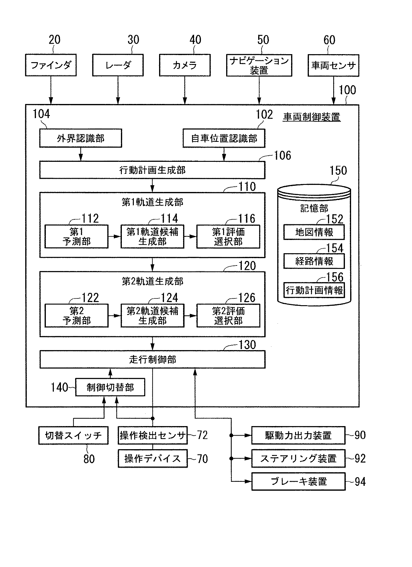
FIG. 1 is a diagram illustrating components included in a vehicle (hereinafter referred to as a host vehicle M) on which a
図1に示すように、自車両Mには、ファインダ20−1から20−7、レーダ30−1から30−6、およびカメラ40等のセンサと、ナビゲーション装置50と、上述した車両制御装置100とが搭載される。
ファインダ20−1から20−7は、例えば、照射光に対する散乱光を測定し、対象までの距離を測定するLIDAR(Light Detection and Ranging、或いはLaser Imaging Detection and Ranging)である。例えば、ファインダ20−1は、フロントグリル等に取り付けられ、ファインダ20−2および20−3は、車体の側面やドアミラー、前照灯内部、側方灯付近等に取り付けられる。ファインダ20−4は、トランクリッド等に取り付けられ、ファインダ20−5および20−6は、車体の側面や尾灯内部等に取り付けられる。上述したファインダ20−1から20−6は、例えば、水平方向に関して150度程度の検出領域を有している。また、ファインダ20−7は、ルーフ等に取り付けられる。ファインダ20−7は、例えば、水平方向に関して360度の検出領域を有している。As shown in FIG. 1, the vehicle M includes a finder 20-1 to 20-7, a radar 30-1 to 30-6, a sensor such as a
The finders 20-1 to 20-7 are, for example, LIDAR (Light Detection and Ranging) that measures scattered light with respect to irradiation light and measures the distance to the target. For example, the finder 20-1 is attached to a front grill or the like, and the finders 20-2 and 20-3 are attached to a side surface of a vehicle body, a door mirror, the inside of a headlamp, a side lamp, and the like. The finder 20-4 is attached to a trunk lid or the like, and the finders 20-5 and 20-6 are attached to the side surface of the vehicle body, the interior of the taillight, or the like. The above-described finders 20-1 to 20-6 have a detection area of about 150 degrees in the horizontal direction, for example. The finder 20-7 is attached to a roof or the like. The finder 20-7 has a detection area of 360 degrees in the horizontal direction, for example.
上述したレーダ30−1および30−4は、例えば、奥行き方向の検出領域が他のレーダよりも広い長距離ミリ波レーダである。また、レーダ30−2、30−3、30−5、30−6は、レーダ30−1および30−4よりも奥行き方向の検出領域が狭い中距離ミリ波レーダである。以下、ファインダ20−1から20−7を特段区別しない場合は、単に「ファインダ20」と記載し、レーダ30−1から30−6を特段区別しない場合は、単に「レーダ30」と記載する。レーダ30は、例えば、FM−CW(Frequency Modulated Continuous Wave)方式によって物体を検出する。 The above-described radars 30-1 and 30-4 are, for example, long-range millimeter wave radars having a detection area in the depth direction wider than other radars. Radars 30-2, 30-3, 30-5, and 30-6 are medium-range millimeter-wave radars that have a narrower detection area in the depth direction than radars 30-1 and 30-4. Hereinafter, when the finders 20-1 to 20-7 are not particularly distinguished, they are simply referred to as “
カメラ40は、例えば、CCD(Charge Coupled Device)やCMOS(Complementary
Metal Oxide Semiconductor)等の個体撮像素子を利用したデジタルカメラである。カメラ40は、フロントウィンドシールド上部やルームミラー裏面等に取り付けられる。カメラ40は、例えば周期的に繰り返し自車両Mの前方を撮像する。The
This is a digital camera using an individual image sensor such as Metal Oxide Semiconductor. The
なお、図1に示す構成はあくまで一例であり、構成の一部が省略されてもよいし、更に別の構成が追加されてもよい。 The configuration illustrated in FIG. 1 is merely an example, and a part of the configuration may be omitted, or another configuration may be added.
図2は、車両制御装置100を中心とした自車両Mの機能構成図である。自車両Mには、ファインダ20、レーダ30、およびカメラ40の他、ナビゲーション装置50と、車両センサ60と、操作デバイス70と、操作検出センサ72と、切替スイッチ80と、走行するための駆動力を出力する駆動力出力装置90、ステアリング装置92、ブレーキ装置94と、車両制御装置100とが搭載される。これらの装置や機器は、CAN(Controller Area Network)通信線等の多重通信線やシリアル通信線、無線通信網等によって互いに接続される。 FIG. 2 is a functional configuration diagram of the host vehicle M centering on the
ナビゲーション装置50は、GNSS(Global Navigation Satellite System)受信機や地図情報(ナビ地図)、ユーザインターフェースとして機能するタッチパネル式表示装置、スピーカ、マイク等を有する。ナビゲーション装置50は、GNSS受信機によって自車両Mの位置を特定し、その位置からユーザによって指定された目的地までの経路を導出する。ナビゲーション装置50により導出された経路は、経路情報154として記憶部150に格納される。自車両Mの位置は、車両センサ60の出力を利用したINS(Inertial Navigation System)によって特定または補完されてもよい。
また、ナビゲーション装置50は、車両制御装置100が手動運転モードを実行している際に、目的地に至る経路について音声やナビ表示によって案内を行う。
なお、自車両Mの位置を特定するための構成は、ナビゲーション装置50とは独立して設けられてもよい。
また、ナビゲーション装置50は、例えば、ユーザの保有するスマートフォンやタブレット端末等の端末装置の一機能によって実現されてもよい。この場合、端末装置と車両制御装置100との間で無線または有線による通信によって情報の送受信が行われる。The
In addition, the
The configuration for specifying the position of the host vehicle M may be provided independently of the
Moreover, the
車両センサ60は、速度を検出する速度センサ、加速度を検出する加速度センサ、鉛直軸回りの角速度を検出するヨーレートセンサ、自車両Mの向きを検出する方位センサ等を含む。 The
操作デバイス70は、例えば、アクセルペダルやステアリングホイール、ブレーキペダル、シフトレバー等を含む。操作デバイス70には、運転者による操作の有無や量を検出する操作検出センサ72が取り付けられている。操作検出センサ72は、例えば、アクセル開度センサ、ステアリングトルクセンサ、ブレーキセンサ、シフト位置センサ等を含む。
操作検出センサ72は、検出結果としてのアクセル開度、ステアリングトルク、ブレーキ踏量、シフト位置等を走行制御部130に出力する。なお、これに代えて、操作検出センサ72の検出結果が、直接的に駆動力出力装置90、ステアリング装置92、またはブレーキ装置94に出力されてもよい。The operation device 70 includes, for example, an accelerator pedal, a steering wheel, a brake pedal, a shift lever, and the like. The operation device 70 is provided with an operation detection sensor 72 that detects the presence / absence and amount of operation by the driver. The operation detection sensor 72 includes, for example, an accelerator opening sensor, a steering torque sensor, a brake sensor, a shift position sensor, and the like.
The operation detection sensor 72 outputs the accelerator opening, steering torque, brake pedal stroke, shift position, and the like as detection results to the
切替スイッチ80は、運転者等によって操作されるスイッチである。切替スイッチ80は、例えば、ステアリングホイールやガーニッシュ(ダッシュボード)等に設置される機械式のスイッチであってもよいし、ナビゲーション装置50のタッチパネルに設けられるGUI(Graphical User Interface)スイッチであってもよい。切替スイッチ80は、運転者等の操作を受け付け、走行制御部130による制御モードを自動運転モードまたは手動運転モードのいずれか一方に指定する制御モード指定信号を生成し、制御切替部140に出力する。
自動運転モードとは、上述したように、運転者が操作を行わない(或いは手動運転モードに比して操作量が小さい、または操作頻度が低い)状態で走行する運転モードであり、より具体的には、行動計画に基づいて駆動力出力装置90、ステアリング装置92、およびブレーキ装置94の一部または全部を制御する運転モードである。The
As described above, the automatic operation mode is an operation mode that travels in a state where the driver does not perform an operation (or the operation amount is small or the operation frequency is low compared to the manual operation mode), and more specifically. Is an operation mode for controlling part or all of the driving force output device 90, the steering device 92, and the brake device 94 based on the action plan.
駆動力出力装置90は、例えば、自車両Mが内燃機関を動力源とした自動車である場合、エンジンおよびエンジンを制御するエンジンECU(Electronic Control Unit)を備える。また、自車両Mが電動機を動力源とした電気自動車である場合、駆動力出力装置90は、走行用モータおよび走行用モータを制御するモータECUを備える。また、自車両Mがハイブリッド自動車である場合、駆動力出力装置90は、エンジンおよびエンジンECUと走行用モータおよびモータECUを備える。
駆動力出力装置90がエンジンのみを含む場合、エンジンECUは、後述する走行制御部130から入力される情報に従って、エンジンのスロットル開度やシフト段等を調整し、車両が走行するための走行駆動力(トルク)を出力する。
また、駆動力出力装置90が走行用モータのみを含む場合、モータECUは、走行制御部130から入力される情報に従って、走行用モータに与えるPWM信号のデューティ比を調整し、上述した走行駆動力を出力する。
また、駆動力出力装置90がエンジンおよび走行用モータを含む場合、エンジンECUおよびモータECUの双方は、走行制御部130から入力される情報に従って、互いに協調して走行駆動力を制御する。The driving force output device 90 includes, for example, an engine and an engine ECU (Electronic Control Unit) that controls the engine when the host vehicle M is an automobile using an internal combustion engine as a power source. In addition, when the host vehicle M is an electric vehicle using an electric motor as a power source, the driving force output device 90 includes a travel motor and a motor ECU that controls the travel motor. When the host vehicle M is a hybrid vehicle, the driving force output device 90 includes an engine and an engine ECU, a travel motor, and a motor ECU.
When the driving force output device 90 includes only the engine, the engine ECU adjusts the throttle opening, the shift stage, and the like of the engine according to information input from the
When the driving force output device 90 includes only the traveling motor, the motor ECU adjusts the duty ratio of the PWM signal given to the traveling motor in accordance with the information input from the traveling
Further, when the driving force output device 90 includes an engine and a traveling motor, both the engine ECU and the motor ECU control the traveling driving force in cooperation with each other according to information input from the traveling
ステアリング装置92は、例えば、電動モータを備える。電動モータは、例えば、ラックアンドピニオン機構に力を作用させて転舵輪の向きを変更する。
ステアリング装置92は、走行制御部130から入力される情報に従って、電動モータを駆動させ、転舵輪の向きを変更する。The steering device 92 includes, for example, an electric motor. For example, the electric motor changes the direction of the steered wheels by applying a force to a rack and pinion mechanism.
The steering device 92 drives the electric motor according to the information input from the
ブレーキ装置94は、例えば、ブレーキキャリパーと、ブレーキキャリパーに油圧を伝達するシリンダと、シリンダに油圧を発生させる電動モータと、制動制御部とを備える電動サーボブレーキ装置である。
電動サーボブレーキ装置の制動制御部は、走行制御部130から入力される情報に従って電動モータを制御し、制動操作に応じたブレーキトルクが各車輪に出力されるようにする。
電動サーボブレーキ装置は、ブレーキペダルの操作によって発生させた油圧を、マスターシリンダを介してシリンダに伝達する機構をバックアップとして備えてよい。
なお、ブレーキ装置94は、上記説明した電動サーボブレーキ装置に限らず、電子制御式油圧ブレーキ装置であってもよい。電子制御式油圧ブレーキ装置は、走行制御部130から入力される情報に従ってアクチュエータを制御して、マスターシリンダの油圧をシリンダに伝達する。
また、ブレーキ装置94は、回生ブレーキを含んでもよい。この回生ブレーキは、駆動力出力装置90に含まれ得る走行用モータにより発電された電力を利用する。The brake device 94 is, for example, an electric servo brake device that includes a brake caliper, a cylinder that transmits hydraulic pressure to the brake caliper, an electric motor that generates hydraulic pressure in the cylinder, and a braking control unit.
The braking control unit of the electric servo brake device controls the electric motor according to the information input from the traveling
The electric servo brake device may include, as a backup, a mechanism that transmits the hydraulic pressure generated by operating the brake pedal to the cylinder via the master cylinder.
The brake device 94 is not limited to the electric servo brake device described above, and may be an electronically controlled hydraulic brake device. The electronically controlled hydraulic brake device controls the actuator in accordance with information input from the traveling
The brake device 94 may include a regenerative brake. This regenerative brake uses electric power generated by a traveling motor that can be included in the driving force output device 90.
[車両制御装置]
以下、車両制御装置100について説明する。車両制御装置100は、例えば、自車位置認識部102と、外界認識部104と、行動計画生成部106と、第1軌道生成部110と、第2軌道生成部120と、走行制御部130と、制御切替部140と、記憶部150とを備える。[Vehicle control device]
Hereinafter, the
自車位置認識部102、外界認識部104、行動計画生成部106、第1軌道生成部110、第2軌道生成部120、走行制御部130、および制御切替部140のうち一部または全部は、CPU(Central Processing Unit)等のプロセッサがプログラムを実行することにより機能するソフトウェア機能部である。また、これらのうち一部または全部は、LSI(Large Scale Integration)やASIC(Application SpecificIntegrated Circuit)等のハードウェア機能部であってもよい。
また、記憶部150は、ROM(Read Only Memory)やRAM(Random Access Memory)、HDD(Hard Disk Drive)、フラッシュメモリ等で実現される。プロセッサが実行するプログラムは、予め記憶部150に格納されていてもよいし、車載インターネット設備等を介して外部装置からダウンロードされてもよい。また、プログラムは、そのプログラムを格納した可搬型記憶媒体が図示しないドライブ装置に装着されることで記憶部150にインストールされてもよい。Some or all of the vehicle position recognition unit 102, the external
The
自車位置認識部102は、記憶部150に格納された地図情報152と、ファインダ20、レーダ30、カメラ40、ナビゲーション装置50、または車両センサ60から入力される情報とに基づいて、自車両Mが走行している車線(走行車線)、および、走行車線に対する自車両Mの相対位置を認識する。
地図情報152は、例えば、ナビゲーション装置50が有するナビ地図よりも高精度な地図情報であり、車線の中央の情報あるいは車線の境界の情報等を含んでいる。
より具体的には、地図情報152には、道路情報と、交通規制情報、住所情報(住所・郵便番号)、施設情報、電話番号情報等が含まれる。
道路情報には、高速道路、有料道路、国道、都道府県道といった道路の種別を表す情報や、道路の車線数、各車線の幅員、道路の勾配、道路の位置(経度、緯度、高さを含む3次元座標)、車線のカーブの曲率、車線の合流および分岐ポイントの位置、道路に設けられた標識等の情報が含まれる。
交通規制情報には、工事や交通事故、渋滞等によって車線が封鎖されているといった情報が含まれる。The own vehicle position recognition unit 102 is based on the
The
More specifically, the
Road information includes information indicating the type of road such as expressway, toll road, national road, prefectural road, road lane number, width of each lane, road gradient, road position (longitude, latitude, height). Information including 3D coordinates), curvature of lane curves, lane merging and branch point positions, signs provided on roads, and the like.
The traffic regulation information includes information that the lane is blocked due to construction, traffic accidents, traffic jams, or the like.
図3は、自車位置認識部102により走行車線L1に対する自車両Mの相対位置が認識される様子を示す図である。自車位置認識部102は、例えば、自車両Mの基準点(例えば重心や後輪軸中心など)の走行車線中央CLからの乖離OS、および自車両Mの進行方向の走行車線中央CLを連ねた線に対してなす角度θを、走行車線L1に対する自車両Mの相対位置として認識する。
なお、これに代えて、自車位置認識部102は、走行車線L1のいずれかの側端部に対する自車両Mの基準点の位置などを、走行車線に対する自車両Mの相対位置として認識してもよい。FIG. 3 is a diagram illustrating how the vehicle position recognition unit 102 recognizes the relative position of the vehicle M with respect to the travel lane L1. The own vehicle position recognition unit 102, for example, connects the deviation OS of the reference point (for example, the center of gravity and the center of the rear wheel axle) of the own vehicle M from the travel lane center CL and the travel lane center CL in the traveling direction of the own vehicle M. The angle θ formed with respect to the line is recognized as the relative position of the host vehicle M with respect to the traveling lane L1.
Instead, the host vehicle position recognition unit 102 recognizes the position of the reference point of the host vehicle M with respect to any side end of the travel lane L1 as the relative position of the host vehicle M with respect to the travel lane. Also good.
外界認識部104は、ファインダ20、レーダ30、カメラ40等から入力される情報に基づいて、周辺車両の位置、および速度、加速度等の状態を認識する。
本実施形態における周辺車両とは、自車両Mの周辺を走行する車両であって、自車両Mと同じ方向に走行する車両である。周辺車両の位置は、周辺車両の重心やコーナー等の代表点で表されてもよいし、周辺車両の輪郭で表現された領域で表されてもよい。
周辺車両の「状態」とは、上記各種機器の情報に基づいて把握される、周辺車両の加速度、車線変更をしているか否か(あるいは車線変更をしようとしているか否か)を含んでもよい。
また、外界認識部104は、周辺車両に加えて、ガードレールや電柱、駐車車両、歩行者その他の物体の位置を認識してもよい。The external
The peripheral vehicle in the present embodiment is a vehicle that travels around the host vehicle M and travels in the same direction as the host vehicle M. The position of the surrounding vehicle may be represented by a representative point such as the center of gravity or corner of the surrounding vehicle, or may be represented by a region expressed by the outline of the surrounding vehicle.
The “state” of the surrounding vehicle may include the acceleration of the surrounding vehicle, whether the lane is changed (or whether the lane is going to be changed), which is grasped based on the information of the various devices.
In addition to the surrounding vehicles, the external
行動計画生成部106は、所定の区間における行動計画を生成する。所定の区間とは、例えば、ナビゲーション装置50により導出された経路のうち、高速道路等の有料道路を通る区間である。なお、これに限らず、行動計画生成部106は、任意の区間について行動計画を生成してもよい。 The action
行動計画は、例えば、順次実行される複数のイベントで構成される。イベントには、例えば、自車両Mを減速させる減速イベントや、自車両Mを加速させる加速イベント、走行車線を逸脱しないように自車両Mを走行させるレーンキープイベント、走行車線を変更させる車線変更イベント、自車両Mに前走車両を追い越させる追い越しイベント、分岐ポイントにおいて所望の車線に変更させたり、現在の走行車線を逸脱しないように自車両Mを走行させたりする分岐イベント、本線に合流するための合流車線において自車両Mを加減速させ、走行車線を変更させる合流イベント等が含まれる。
例えば、有料道路(例えば高速道路等)においてジャンクション(分岐点)が存在する場合、車両制御装置100は、自動運転モードにおいて、自車両Mを目的地の方向に進行するように車線を変更したり、車線を維持したりする必要がある。従って、行動計画生成部106は、地図情報152を参照して経路上にジャンクションが存在していると判明した場合、現在の自車両Mの位置(座標)から当該ジャンクションの位置(座標)までの間に、目的地の方向に進行することができる所望の車線に車線変更するための車線変更イベントを設定する。なお、行動計画生成部106によって生成された行動計画を示す情報は、行動計画情報156として記憶部150に格納される。The action plan is composed of, for example, a plurality of events that are sequentially executed. Examples of the event include a deceleration event for decelerating the host vehicle M, an acceleration event for accelerating the host vehicle M, a lane keeping event for driving the host vehicle M so as not to deviate from the traveling lane, and a lane change event for changing the traveling lane. In order to merge with the overtaking event in which the own vehicle M overtakes the preceding vehicle, the branch event in which the own vehicle M is driven so as not to deviate from the current traveling lane, or the main line , A merging event for accelerating / decelerating the own vehicle M in the merging lane and changing the traveling lane is included.
For example, when a junction (branch point) exists on a toll road (for example, an expressway), the
図4は、ある区間について生成された行動計画の一例を示す図である。図4に示すように、行動計画生成部106は、目的地までの経路に従って走行した場合に生じる場面を分類し、個々の場面に即したイベントが実行されるように行動計画を生成する。なお、行動計画生成部106は、自車両Mの状況変化に応じて動的に行動計画を変更してもよい。 FIG. 4 is a diagram illustrating an example of an action plan generated for a certain section. As illustrated in FIG. 4, the action
行動計画生成部106は、例えば、生成した行動計画を、外界認識部104によって認識された外界の状態に基づいて変更(更新)してもよい。一般的に、車両が走行している間、外界の状態は絶えず変化する。特に、複数の車線を含む道路を自車両Mが走行する場合、周辺車両との距離間隔は相対的に変化する。
例えば、前方の車両が急ブレーキを掛けて減速したり、隣の車線を走行する車両が自車両M前方に割り込んで来たりする場合、自車両Mは、前方の車両の挙動や、隣接する車線の車両の挙動に合わせて速度や車線を適宜変更しつつ走行する必要がある。従って、行動計画生成部106は、上述したような外界の状態変化に応じて、制御区間ごとに設定したイベントを変更してもよい。For example, the action
For example, when the vehicle ahead is decelerated by applying a sudden brake, or when a vehicle traveling in an adjacent lane enters the front of the host vehicle M, the host vehicle M determines the behavior of the preceding vehicle or the adjacent lane. It is necessary to travel while appropriately changing the speed and lane according to the behavior of the vehicle. Therefore, the action
具体的には、行動計画生成部106は、車両走行中に外界認識部104によって認識された周辺車両の速度が閾値を超えたり、自車線に隣接する車線を走行する周辺車両の移動方向が自車線方向に向いたりした場合に、自車両Mが走行予定の運転区間に設定されたイベントを変更する。
例えば、レーンキープイベントの後に車線変更イベントが実行されるようにイベントが設定されている場合において、外界認識部104の認識結果によって当該レーンキープイベント中に車線変更先の車線後方から車両が閾値以上の速度で進行してきたことが判明した場合、行動計画生成部106は、レーンキープイベントの次のイベントを車線変更から減速イベントやレーンキープイベント等に変更する。この結果、車両制御装置100は、外界の状態に変化が生じた場合においても、安全に自車両Mを自動走行させることができる。Specifically, the action
For example, when the event is set so that the lane change event is executed after the lane keep event, the vehicle is more than the threshold from the rear of the lane to which the lane is changed during the lane keep event according to the recognition result of the
第1軌道生成部110は、第1の周期で処理を実行し、第1軌道を生成する。また、第1軌道生成部110は、第2軌道生成部120の処理結果を取得し、取得した第2軌道生成部120の処理結果を反映させて第1軌道を生成する。 The first
第1軌道生成部110は、第1の将来状態を予測する第1予測部112、第1軌道候補生成部114、および第1評価選択部116を含む。第1予測部112は、自車両の周辺環境の将来の状態を予測する。将来の状態とは、例えば地図情報152に基づいて予測される自車両Mが将来走行する可能性のある道路の状態である。道路の状態とは、例えば、車線の増減や、車線の分岐、カーブの曲率や向き等である。また、第1予測部112は、外界認識部104によって認識された周辺車両について、周辺車両の将来の位置変化を予測する(後述参照)。 The first
第1軌道候補生成部114は、第1予測部112の予測結果に基づいて、複数の第1軌道の候補を生成する。第1評価選択部116は、第1軌道候補生成部114により生成された複数の軌道の中から、安全性と計画性とに基づいて自車両Mが走行する第1軌道を選択する。第1予測部112および第1評価選択部116の処理の具体例については後述する。 The first trajectory
[レーンキープイベント]
第1軌道生成部110は、行動計画に含まれるレーンキープイベントが走行制御部130により実施される際に、定速走行、追従走行、減速走行、カーブ走行、障害物回避走行などのうちいずれかの走行態様を決定する。
例えば、第1軌道生成部110は、自車両Mの前方に周辺車両が存在しない場合に、走行態様を定速走行に決定する。
また、第1軌道生成部110は、前走車両に対して追従走行するような場合に、走行態様を追従走行に決定する。
また、第1軌道生成部110は、外界認識部104により前走車両の減速が認識された場合や、停車や駐車などのイベントを実施する場合に、走行態様を減速走行に決定する。
また、第1軌道生成部110は、外界認識部104により自車両Mがカーブ路に差し掛かったことが認識された場合に、走行態様をカーブ走行に決定する。
また、第1軌道生成部110は、外界認識部104により自車両Mの前方に障害物が認識された場合に、走行態様を障害物回避走行に決定する。[Lane Keep Event]
When the lane keeping event included in the action plan is executed by the traveling
For example, when there is no surrounding vehicle in front of the host vehicle M, the first
Moreover, the 1st track | orbit production |
Moreover, the 1st track | orbit production |
Further, the first
Further, the first
第1軌道生成部110は、決定した走行態様に基づいて、第1軌道を生成する。軌道とは、自車両Mが第1軌道生成部110により決定された走行態様に基づいて走行する場合に、到達することが想定される将来の目標位置を、所定時間ごとにサンプリングした点の集合(軌跡)である。なお、第2軌道生成部120が生成する第2軌道も同様であり、第1軌道と第2軌道は時間的な刻み幅が異なってよい。また、第1軌道と第2軌道は、時間的な刻み幅は同じで、生成する周期のみが異なってもよい。 The first
第1軌道生成部110は、少なくとも、自車位置認識部102または外界認識部104により認識された自車両Mの前方に存在する対象OBの速度、および自車両Mと対象OBとの距離に基づいて自車両Mの目標速度を算出する。第1軌道生成部110は、算出した目標速度に基づいて第1軌道を生成する。対象OBとは、前走車両や、合流地点、分岐地点、目標地点などの地点、障害物などの物体等を含む。 The first
以下、特に対象OBの存在を考慮しない場合と、考慮する場合との双方における軌道の生成について説明する。
図5は、第1軌道生成部110により生成される第1軌道の一例を示す図である。図5中(A)に示すように、例えば、第1軌道生成部110は、自車両Mの現在位置を基準に、現時刻から所定時間Δt経過するごとに、K(1)、K(2)、K(3)、…といった将来の目標位置(軌道点)を連ねたものを、自車両Mの第1軌道として設定する。以下、これら目標位置を区別しない場合、単に「目標位置K」と表記する。
例えば、目標位置Kの個数は、目標時間Tに応じて決定される。例えば、第1軌道生成部110は、目標時間Tを10秒とした場合、この10秒間において、所定時間Δt(例えば0.1秒)刻みで目標位置Kを走行車線の中央線上に設定し、これら複数の目標位置Kの配置間隔を走行態様に基づいて決定する。第1軌道生成部110は、例えば、走行車線の中央線を、地図情報152に含まれる車線の幅員等の情報から導出してもよいし、予め地図情報152に含まれている場合に、この地図情報152から取得してもよい。Hereinafter, the generation of the trajectory in both the case where the presence of the target OB is not considered and the case where it is considered will be described.
FIG. 5 is a diagram illustrating an example of the first trajectory generated by the first
For example, the number of target positions K is determined according to the target time T. For example, when the target time T is set to 10 seconds, the first
例えば、第1軌道生成部110は、走行態様を定速走行に決定した場合、図5中(A)に示すように、等間隔で複数の目標位置Kを設定して第1軌道を生成する。 For example, when the travel mode is determined to be constant speed travel, the first
また、第1軌道生成部110は、走行態様を減速走行に決定した場合(追従走行において前走車両が減速した場合も含む)、図5中(B)に示すように、到達する時刻がより早い目標位置Kほど間隔を広くし、到達する時刻がより遅い目標位置Kほど間隔を狭くして第1軌道を生成する。この場合において、前走車両が対象OBに設定されたり、前走車両以外の合流地点や、分岐地点、目標地点などの地点、障害物等が対象OBに設定されたりすることがある。これにより、自車両Mからの到達する時刻が遅い目標位置Kが自車両Mの現在位置と近づくため、後述する走行制御部130が自車両Mを減速させることになる。 In addition, when the first
図5(A)、(B)に示すような状況において、第1軌道候補生成部114が生成し得る第1軌道の候補は、多くはならず、一つの第1軌道の候補のみが生成されてもよい。この場合、第1評価選択部116は、自動的に、第1軌道候補生成部114により生成された一つの第1軌道の候補を、第1軌道として選択する。 5A and 5B, the number of first trajectory candidates that can be generated by the first trajectory
また、図5中(C)に示すように、道路がカーブ路である場合に、第1軌道生成部110は、走行態様をカーブ走行に決定する。この場合、第1軌道生成部110は、例えば、道路の曲率に応じて、複数の目標位置Kを自車両Mの進行方向に対する横位置(車線幅方向の位置であり、進行方向に略直行する方向)を変更しながら配置して第1軌道を生成する。 As shown in FIG. 5C, when the road is a curved road, the first
また、図5中(D)に示すように、自車両Mの前方の道路上に人間や停止車両等の障害物OBが存在する場合、第1軌道生成部110は、走行態様を障害物回避走行に決定する。
この場合、第1軌道生成部110は、この障害物OBを回避して走行するように、複数の目標位置Kを配置して第1軌道を生成する。Further, as shown in FIG. 5D, when an obstacle OB such as a person or a stopped vehicle exists on the road ahead of the host vehicle M, the first
In this case, the first
[カーブ走行時における軌道の生成]
ここで、一例として走行態様がカーブ走行である場合に、第1軌道生成部110が行う処理について説明する。第1予測部112が、将来、自車両Mが走行する予定の道路がカーブ路であることを予測する。第1軌道候補生成部114が、自車両Mが走行する予定のカーブ路の道路情報(道路の幅や車線のカーブの曲率等)を取得する。第1軌道候補生成部114は、道路情報に基づいて、自車両が走行するカーブ路の形状を仮想的に直線形状に変換した情報を生成する。例えば、第1軌道候補生成部114は、地図情報152から経路情報154によって示される経路に存在する道路の形状を示す情報を抽出し、上記道路の形状を示す情報上において道路の形状を仮想的に直線形状に変換した情報を生成する。[Generation of track during curve driving]
Here, as an example, a process performed by the first
第1軌道候補生成部114は、自車両Mの位置(始点)、目標点(終点)、および自車両Mの速度、ヨーレート角ならびにステアリング角に基づいて、直線形状に変換された道路上に沿った第1軌道の候補を複数生成する。第1軌道候補生成部114は、走行軌道の軌道点の各点について、加減速度や転向角、想定されるヨーレートなどが第1所定範囲以内に収まっているように複数の第1軌道の候補を生成する。第1軌道候補生成部114は、上記の条件下で、例えばスプライン関数に基づいて、スプライン曲線を生成する。 The first trajectory
例えば、始点Psの座標(x0,y0)において自車両Mの速度がv0であり、加速度がa0であるものとする。自車両Mの速度v0は、速度のx方向成分vx0とy方向成分vy0とが合成された速度ベクトルである。自車両Mの加速度a0は、加速度のx方向成分ax0とy方向成分ay0とが合成された加速度ベクトルである。終点Peの座標(x 1,y1)において自車両Mの速度がv1であり、加速度がa1であるものとする。自車両Mの速度v1は、速度のx方向成分vx1とy方向成分vy1とが合成された速度ベクトルである。自車両Mの加速度a1は、加速度のx方向成分ax1とy方向成分ay1とが合成された加速度ベクトルである。 For example, the coordinates of the starting point Ps (x0, Y0), The speed of the vehicle M is v0And the acceleration is a0Suppose that The speed v0 of the host vehicle M is the x-direction component v of the speed.x0And y-direction component vy0Are the combined velocity vectors. Acceleration a of own vehicle M0Is the x-direction component of acceleration ax0And y-direction component ay0Are the combined acceleration vectors. End point Pe coordinates (x 1, Y1), The speed of the vehicle M is v1And the acceleration is a1Suppose that Speed v of own vehicle M1Is the x-direction component of velocity vx1And y-direction component vy1Are the combined velocity vectors. Acceleration a of own vehicle M1Is the x-direction component of acceleration ax1And y-direction component ay1Are the combined acceleration vectors.
第1軌道候補生成部114は、自車両Mが始点Psから終点Peまでに至る単位時間Tが経過する周期中の時間tごとに、目標点(x,y)を設定する。目標点(x,y)の演算式は、式(1)および式(2)のスプライン関数により表される。 The first trajectory
式(1)および式(2)において、m5、m4、およびm3は、式(3)、式(4)および式(5)のように表される。また、式(1)および式(2)における係数k1およびk2は、同じであってもよいし相違していてもよい。In Formula (1) and Formula (2), m 5 , m 4 , and m 3 are represented as Formula (3), Formula (4), and Formula (5). Further, the coefficients k 1 and k 2 in the expressions (1) and (2) may be the same or different.
式(3)、式(4)および式(5)においてp0は始点Psにおける自車両Mの位置(x0,y0)であり、p1は終点Peにおける自車両Mの位置(x1,y1)である。In Expressions (3), (4), and (5), p 0 is the position (x 0 , y 0 ) of the host vehicle M at the start point Ps, and p 1 is the position (x 1 ) of the host vehicle M at the end point Pe. , Y 1 ).
第1軌道候補生成部114は、式(1)および式(2)におけるvx0およびvy0に自車両Mの速度にゲインを掛け合わせた値を代入して、単位時間Tを時刻tごとに式(1)および式(2)の演算結果により特定された目標点(x(t),y(t))を取得する。これにより、第1軌道候補生成部114は、始点Psと終点Peとを複数の目標点(x(t),y(t))により補間したスプライン曲線を得る。The first track
図6は、直線形状の道路上に生成された走行軌道(スプライン曲線)の一例を示す図である。第1軌道候補生成部114は、図6(A)に示すようなスプライン曲線を、走行軌道Tgとして生成する。 FIG. 6 is a diagram illustrating an example of a traveling track (spline curve) generated on a straight road. The first track
第1軌道候補生成部114は、直線形状の道路上に生成した走行軌道Tgに対し、変換の逆変換を行うことで、図6(B)に示すような直線形状に変換される前の道路の形状における自車両Mの走行軌道Tg#を生成する。例えば、第1軌道候補生成部114は、走行軌道Tgとして生成されたスプライン曲線を、所定幅を有する点列で表現し、それぞれの点を逆変換することで得られる点列を、走行軌道Tg#とする。これによって、第1軌道候補生成部114は、直線形状の道路形状を元の道路形状に逆変換するとともに、直線形状の道路上において生成された走行軌道Tgを変換して、元の道路上に新たな走行軌道Tg#を生成する。 The first trajectory
第1評価選択部116は、第1軌道候補生成部114により生成された複数の第1軌道候補の中から、安全性と計画性とに基づいて自車両Mが走行する第1軌道を選択する。例えば、第1評価選択部116は、下記式(6)に示す評価関数fに基づいて、最適な軌道を選択する。w1(=(w+1)−1)およびw2は、重み係数であり、e1は安全性指数であり、e2は計画性指数である。安全性指数とは、例えば、自車両Mと障害物OBとの距離、各軌道点における加減速度や操舵角、想定されるヨーレートなどに基づいて決定される評価値である。例えば自車両Mと障害物OBとの距離が遠いほど、加減速度や操舵角の変化量などが小さいほど、安全性指数が高いものと評価される。計画性指数とは、上位で生成された軌道に対する追従性、および/または軌道の短さに基づく評価値である。The first
上位で生成された軌道における「上位」とは、第1軌道生成部110を対象とする場合は行動計画生成部106を指す。行動計画生成部106が、「中央車線を走行し、分岐点手前で右に車線変更する」と決定した場合、途中で左に車線変更するような軌道は、計画性指数が低いと第1評価選択部116により判定される。また、途中で左に車線変更する軌道は、軌道の短さの点からも第1評価選択部116により低く評価される。また、「上位」とは、第2軌道生成部120を対象とする場合は第1軌道生成部110を指す。第2軌道生成部120の処理では、第1軌道生成部110が生成した第1軌道から乖離するほど計画性指数が低いと判定される。例えば、軌道が滑らかでない程、また、軌道が長い程、計画性指数は、第2軌道生成部120の第2評価選択部126により低く評価される。
f=w1e1(w2e2+1)・・・(6)“Upper rank” in the higher-order generated trajectory refers to the action
f = w 1 e 1 (w 2 e 2 +1) (6)
図7は、安全性指数および計画性指数に基づく、軌道判定の基準の一例を示す図である。縦軸は計画性を示し、横軸は安全性指数を示している。評価関数fは、図7中、矢印ar方向に評価が上昇する勾配を有する。評価関数fは、例えばf*=w1e1+w2e2のように単純な加重和として求める場合に比して、安全性指数が極めて低い軌道の評価を下げ、これを除外することができる。このように第1評価選択部116は、安全性を十分に考慮した上で、計画性を加味した軌道を選択することができる。FIG. 7 is a diagram illustrating an example of a criterion for trajectory determination based on the safety index and the planning index. The vertical axis shows planning, and the horizontal axis shows the safety index. The evaluation function f has a gradient in which the evaluation increases in the direction of the arrow ar in FIG. The evaluation function f can be evaluated by lowering the evaluation of a trajectory having a very low safety index and excluding it as compared with a case where it is obtained as a simple weighted sum, for example, f * = w 1 e 1 + w 2 e 2. it can. In this way, the first
[車線変更イベント]
また、車線変更イベントが実施される場合、第1軌道生成部110は、車線変更のターゲットとなるターゲット位置の設定、車線変更可否判定、将来状態の予測、車線変更軌道生成、軌道評価といった処理を行う。ターゲット位置は、例えば隣接車線において選択された2台の周辺車両の間に設定される相対的な位置である。また、第1軌道生成部110は、分岐イベントや合流イベントが実施される場合にも、同様の処理を行ってよい。[Lane change event]
When a lane change event is performed, the first
第1予測部112は、周辺車両の将来状態を予測する。まず、第1予測部112は、周辺車両mA、mB、およびmCを特定する。図8は、自車両Mと周辺車両との位置関係の一例を示す図である。図8では、車両の位置関係は、mA−mB−mC−Mであるものとする。周辺車両mAは、自車両Mが走行する車線において自車両Mの直前を走行する車両(前走車両)である。周辺車両mBは、隣接車線を走行する上記「2台の周辺車両」のうち、ターゲット位置の直前に存在する車両であり、周辺車両mCは、隣接車線を走行する上記「2台の周辺車両」のうち、ターゲット位置の直後を走行する車両である。 The
次に、第1予測部112が、周辺車両mA、mB、およびmCの将来の位置変化を予測する。第1予測部112は、例えば、車両が現在の速度を保ったまま走行すると仮定した定速度モデル、車両が現在の加速度を保ったまま走行すると仮定した定加速度モデル、後方の車両が前方の車両と一定距離を保ちながら追従して走行すると仮定した追従走行モデル、その他、種々のモデルに基づいて予測する。 Next, the
図9は、第1予測部112が予測した周辺車両の位置関係の一例を示す図である。図9では、周辺車両の速度は、mA>mC>mBであるものとする。図9における縦軸は、自車両Mを基準とした進行方向に関する変位(x)を、横軸は経過時間(t)を、それぞれ表している。図9に示す例では、第1予測部112が、定速度モデルに基づいて、周辺車両の状態を予測した結果を示している。 FIG. 9 is a diagram illustrating an example of a positional relationship of surrounding vehicles predicted by the
第1軌道候補生成部114は、第1予測部112により予測された将来状態に基づいて、車線変更のための実現可能な第1軌道の候補を複数生成する。図10は、自車両Mが車線変更する場合の自車両と周辺車両の位置関係の一例を示す図である。図9と重複する説明は省略する。図10中、軌道ORのような第1軌道の候補は複数の組み合わせで生成される。 The first track
第1軌道候補生成部114が、車線変更可能領域に対応する車線変更可能期間Pを導出するために、自車両Mと、周辺車両mA、mB、およびmCの位置変化を類型化する。次に、第1軌道候補生成部114は、第1予測部112により予測された周辺車両mA、mB、およびmCの位置変化に基づいて、車線変更するためのターゲット位置および車線変更可能期間Pを決定する。第1軌道候補生成部114は、予測された周辺車両mA、mB、およびmCの位置変化に基づいて、車線変更可能期間の終了時点を決定する。
第1軌道候補生成部114は、例えば、周辺車両mCが周辺車両mBに追いつき、周辺車両mCと周辺車両mBとの距離が所定距離となったときを車線変更可能期間Pの終了時点と決定する。In order to derive the lane changeable period P corresponding to the lane changeable region, the first track
For example, the first track
ここで、車線変更の開始時点を決定するためには、「自車両Mが周辺車両mCを追い抜く時点」といった要素が存在し、これを解くためには自車両Mの加速に関する仮定が必要となる。この点、第1軌道候補生成部114は、現在の自車両Mの速度から急加速とならない範囲内で、法定速度を上限として速度変化曲線を導出し、周辺車両mCの位置変化と合わせて「自車両Mが周辺車両mCを追い抜く時点」を決定する。なお、第1軌道候補生成部114は、例えば、減速するのであれば、現在の自車両Mの速度から所定程度(例えば2割程度)減速するものとし、急減速にならない範囲内で速度変化曲線を導出する。 Here, in order to determine the start time of the lane change, there exists an element such as “the time when the host vehicle M overtakes the surrounding vehicle mC”, and in order to solve this, an assumption regarding the acceleration of the host vehicle M is required. . In this regard, the first trajectory
次に、第1軌道候補生成部114は、車線変更するための軌道ORを生成し、生成された軌道ORが設定条件を満たす軌道であるか否かを判定する。設定条件とは、例えば、軌道点の各点について、加減速度や転向角、想定されるヨーレートなどが所定の範囲内に収まっていることである。設定条件を満たす軌道を生成できた場合、第1評価選択部116が、設定条件を満たす軌道のうち、評価が高い軌道を選択する。第1軌道生成部110は、選択された軌道の情報を第2軌道生成部120に出力する。一方、設定条件を満たす軌道を生成できなかった場合、第1軌道生成部110は、待機状態やターゲット位置を再設定する処理等を行ってもよい。 Next, the first track
図11は、第1軌道候補生成部114が軌道を生成する様子を示す図である。例えば、第1軌道候補生成部114は、自車両Mが周辺車両mAと干渉、又は接触せずに、将来のある時刻において自車両Mが周辺車両mBと周辺車両mCとの間に位置するように複数の軌道を生成する。例えば、第1軌道候補生成部114は、現在の自車両Mの位置から、車線変更先の車線の中央、且つ車線変更の終了地点までをスプライン曲線等の多項式曲線を用いて滑らかに繋ぎ、この曲線上に等間隔あるいは不等間隔で目標位置Kを所定個数配置する。第1評価選択部116は、前述したように安全性指数および計画性指数に基づく、軌道判定の基準を用いて、各軌道を評価して、評価の高い軌道(図11中、目標位置Kにより形成された軌道)を選択する。 FIG. 11 is a diagram illustrating a state in which the first trajectory
[第2軌道生成部]
第2軌道生成部120は、第1の周期より短い第2の周期で処理を実行し、第1軌道生成部110の処理結果を取得し、取得した第1軌道生成部110の処理結果を反映させて第2軌道を生成する。[Second orbit generator]
The second
第2軌道生成部120は、第1軌道の候補が生成される場合よりも緩やかな基準である第2設定条件を満たす第2軌道の候補を複数生成する。第2設定条件とは、例えば、軌道点の各点について、加減速度や転向角、想定されるヨーレートなどが第1所定範囲よりも大きい第2所定範囲以内に収まっていることである。すなわち、第2軌道生成部120は、第2所定範囲に収まるように加減速度や転向角、想定されるヨーレートを変化させるように軌道を生成するため、自車両Mを急峻に制御することができる。 The second
第2軌道生成部120は、第2の将来状態を予測する第2予測部122、第2軌道候補生成部124、および第2評価選択部126を備える。第2予測部122は、第1予測部112と同様に、将来の状態を予測する。第2軌道候補生成部124は、第1軌道候補生成部114と同様に、複数の第2軌道の候補を生成する。第2軌道の対象期間は、例えば3秒であり、第1軌道の対象期間(例えば10秒)よりも短い。 The second
第2軌道生成部120は、第1軌道生成部110より短い第2の周期で処理を実行するため、予測していなかった障害物が出現し、自車両Mに干渉する可能性が生じた場合に、急峻に障害物を回避可能な第2軌道を生成することができる。予測していなかった障害物とは、例えば自車両Mが走行する車線へ急に割り込んできた周辺車両や、自車両Mの直前に急に飛び出してきた周辺車両や物体(人)等である。 Since the second
図12は、予測していない人が自車両Mの走行する予定の軌道付近に飛び出してきた場合の一例を示す図である。図12に示すように、自車両Mの前方の道路上に予測していない人等の障害物OBが飛び出してきた場合、第2軌道生成部120は、障害物を回避するための第2軌道を生成する。この場合、第2軌道生成部120は、第1軌道生成部110に生成された第1軌道とは異なる第2軌道を生成する。第2軌道生成部120は、第1軌道生成部110により生成された第1軌道(図12中、K)とは異なる軌道であって、障害物OBを回避して走行するように、複数の目標位置を配置して第2軌道(図12中、K#)を生成する。なお、図12に示す例は、第1軌道と第2軌道との目標位置の時間的な刻み幅が異なる場合を示している。 FIG. 12 is a diagram illustrating an example of a case where an unpredicted person jumps out in the vicinity of a track on which the host vehicle M is scheduled to travel. As shown in FIG. 12, when an obstacle OB such as an unpredicted person jumps out on the road ahead of the host vehicle M, the second
より具体的には、例えば、第2軌道候補生成部124が、障害物OBを回避するための複数の第2軌道の候補を生成する。第2評価選択部126は、第2軌道候補生成部124により生成された複数の第2軌道の候補のうちから、障害物OBを回避することができ、且つ第1軌道生成部110により生成された第1軌道になるべく近い軌道を高く評価し、第2軌道として選択する。第2評価選択部126は、安全性と計画性とに基づいて、生成された複数の軌道の中から自車両Mが走行する第2軌道を選択する。 More specifically, for example, the second trajectory
例えば、第2評価選択部126は、下記の式(7)に示す評価関数fに基づいて、最適な軌道を選択する。w3(=(w+1)−1)およびw4は、重み係数であり、e3は安全性指数であり、e4は計画性指数である。安全性指数とは、例えば、自車両Mと障害物OBとの距離(間隔)、各軌道点における加減速度や操舵角、想定されるヨーレートなどに基づいて決定される評価値である。例えば自車両Mと障害物OBとの距離が遠いほど、加減速度や操舵角の変化量などが小さいほど、安全性指数が高いものと評価される。計画性指数とは、上位で生成された軌道に対する追従性、および/または軌道の短さに基づく評価値である。
f=w3e3(w4e4+1)・・・(7)For example, the second
f = w 3 e 3 (w 4 e 4 +1) (7)
評価関数fは、例えばf*=w3e3+w4e4のように単純な加重和として求める場合に比して、安全性指数が極めて低い軌道の評価を下げ、これを除外することができる。
このように、第2軌道生成部120は、安全性を十分に考慮した上で、計画性を加味した第2軌道を選択することができる。この結果、第2軌道生成部120は、予測していなかった障害物が出現した場合であっても、障害物OBを回避可能な第2軌道を生成することができる。The evaluation function f is lower than the evaluation of a trajectory having a very low safety index, and can be excluded as compared with the case where it is obtained as a simple weighted sum, for example, f * = w 3 e 3 + w 4 e 4 it can.
As described above, the second
また、第2軌道生成部120は、自車両Mが外部環境に基づいて停止、または低速走行している状態から自車両Mを加速させる場合、第1軌道より早く自車両Mを発進させる第2軌道を生成する。これについては、後に図13等を用いて説明する。 In addition, the second
[走行制御]
走行制御部130は、制御切替部140による制御によって、制御モードを自動運転モードあるいは手動運転モードに設定し、設定した制御モードに従って、駆動力出力装置90、ステアリング装置92、およびブレーキ装置94の一部または全部を含む制御対象を制御する。走行制御部130は、自動運転モード時において、行動計画生成部106によって生成された行動計画情報156を読み込み、読み込んだ行動計画情報156に含まれるイベントに基づいて制御対象を制御する。[Running control]
The traveling
例えば、このイベントがレーンキープイベントである場合、走行制御部130は、第2軌道生成部120により生成された第2軌道に従い、ステアリング装置92における電動モータの制御量(例えば回転数)と、駆動力出力装置90におけるECUの制御量(例えばエンジンのスロットル開度やシフト段等)と、を決定する。具体的には、走行制御部130は、軌道の目的位置K間の距離と、目的位置Kを配置した際の所定時間Δtとに基づいて、所定時間Δtごとの自車両Mの速度を導出し、この所定時間Δtごとの速度に従って、駆動力出力装置90におけるECUの制御量を決定する。また、走行制御部130は、目的位置Kごとの自車両Mの進行方向と、この目的位置を基準とした次の目的位置の方向とのなす角度に応じて、ステアリング装置92における電動モータの制御量を決定する。 For example, when this event is a lane keeping event, the traveling
また、上記イベントが車線変更イベントである場合、走行制御部130は、第2軌道生成部120により生成された第2軌道に従い、ステアリング装置92における電動モータの制御量と、駆動力出力装置90におけるECUの制御量とを決定する。 When the event is a lane change event, the traveling
走行制御部130は、イベントごとに決定した制御量を示す情報を、対応する制御対象に出力する。これによって、制御対象の各装置(90、92、94)は、走行制御部130から入力された制御量を示す情報に従って、自装置を制御することができる。また、走行制御部130は、車両センサ60の検出結果に基づいて、決定した制御量を適宜調整する。 The traveling
また、走行制御部130は、手動運転モード時において、操作検出センサ72により出力される操作検出信号に基づいて制御対象を制御する。例えば、走行制御部130は、操作検出センサ72により出力された操作検出信号を、制御対象の各装置にそのまま出力する。 In addition, the traveling
制御切替部140は、行動計画生成部106によって生成され、記憶部150に格納された行動計画情報156に基づいて、走行制御部130による自車両Mの制御モードを自動運転モードから手動運転モードに、または手動運転モードから自動運転モードに切り換える。また、制御切替部140は、切替スイッチ80から入力される制御モード指定信号に基づいて、走行制御部130による自車両Mの制御モードを自動運転モードから手動運転モードに、または手動運転モードから自動運転モードに切り換える。すなわち、走行制御部130の制御モードは、運転者等の操作によって走行中や停車中に任意に変更することができる。 Based on the
また、制御切替部140は、操作検出センサ72から入力される操作検出信号に基づいて、走行制御部130による自車両Mの制御モードを自動運転モードから手動運転モードに切り換える。例えば、制御切替部140は、操作検出信号に含まれる操作量が閾値を超える場合、すなわち、操作デバイス70が閾値を超えた操作量で操作を受けた場合、走行制御部130の制御モードを自動運転モードから手動運転モードに切り換える。例えば、自動運転モードに設定された走行制御部130によって自車両Mが自動走行している場合において、運転者によってステアリングホイール、アクセルペダル、またはブレーキペダルが閾値を超える操作量で操作された場合、制御切替部140は、走行制御部130の制御モードを自動運転モードから手動運転モードに切り換える。これによって、車両制御装置100は、人間等の物体が車道に飛び出して来たり、周辺車両mAが急停止したりした際に運転者により咄嗟になされた操作によって、切替スイッチ80の操作を介さずに直ぐさま手動運転モードに切り替えることができる。この結果、車両制御装置100は、運転者による緊急時の操作に対応することができ、走行時の安全性を高めることができる。 The control switching unit 140 switches the control mode of the host vehicle M by the
[停止時から発進時の制御]
ここで、自動運転モードにおいて、自車両Mが停車している状態から発進するときの処理について説明する。前述したように第2評価選択部126は、安全性と計画性とに基づいて、軌道を評価する。周辺に障害物が存在しない場合、安全性は軌道の態様によって大きく変化しない。このため、第2評価選択部126は、第1軌道生成部110により生成された第1軌道になるべく近い軌道を高く評価し、第2軌道として選択することになる。
一方、障害物を回避する場合、第2評価選択部126は、障害物を回避することを重視しつつ、第1軌道生成部110によって生成された第1軌道になるべく近い軌道を高く評価し、第2軌道として選択することになる。[Control from stop to start]
Here, a process when starting from a state where the host vehicle M is stopped in the automatic driving mode will be described. As described above, the second
On the other hand, when avoiding an obstacle, the second
しかしながら、自車両Mが停車時から発進時において、上述したように第2評価選択部126が、処理の周期が長い第1軌道生成部110により生成された第1軌道を優先した第2軌道を生成すると、自車両Mが発進できる状態になっても、自車両Mが応答性よく発進できない場合がある。第1軌道には、自車両Mを停止状態にする部分が含まれるためである。また、第2評価選択部126が行う評価および選択の基準には、「応答性よく発進」といった基準は含まれていない。このため、自車両Mの発進の応答性が悪くても評価値が低下しない。従って、本実施形態の第2軌道生成部120は、停止時から発進時における例外処理として、以下に説明するように、自車両Mを応答性よく発進させる軌道を生成する。 However, when the host vehicle M starts from a stop, the second
図13は、第2軌道生成部120により実行される処理の流れを示すフローチャートである。まず、第2軌道生成部120は、自車両Mが外部環境により停止している状態であるか否かを判定する(ステップS100)。自車両Mが外部環境により停止している状態とは、自車両Mが自動運転の目的地に向かって走行したいにも関わらず、外部環境によって停止せざる得ない状態である。この状態には、例えば信号が停止を示していることで自車両Mが停止している状態や、渋滞により自車両Mが停止する必要がある状態などが含まれる。自車両Mが外部環境により停止している状態でないと判定した場合、本フローチャートの処理は終了する。 FIG. 13 is a flowchart showing a flow of processing executed by the second
一方、自車両Mが外部環境により停止している状態であると判定した場合、第2軌道生成部120は、自車両Mが外部環境の変化により発進可能であるか否かを判定する(ステップS102)。自車両Mが外部環境の変化により発進可能な状態とは、例えば信号が止まれを示す状態から進めを示す状態に変わった場合や、渋滞時に自車両Mの直前の車両が発進した場合等である。 On the other hand, when it is determined that the host vehicle M is stopped by the external environment, the second
自車両Mが外部環境の変化により発進可能でないと判定した場合、本フローチャートの処理は終了する。自車両Mが外部環境の変化により発進可能であると判定した場合、第2軌道生成部120は、自車両Mを応答性よく発進させるための第2軌道を生成する(ステップS104)。この場合、例えば、第2評価選択部126が、評価値を導出する場合に計画性指数の要素である第1軌道への追従性を一時的に無視して、第2軌道を評価および選択する。これにより本フローチャートの1ルーチンの処理は終了する。 When it is determined that the host vehicle M cannot start due to a change in the external environment, the processing of this flowchart ends. When it is determined that the host vehicle M can start due to a change in the external environment, the second
図14は、自車両Mを応答性よく発進させるための第2軌道を生成する処理を説明するための図である。図の縦軸は、現在の自車両Mの位置から自車両Mの進行方向に対する変位(x)であり、横軸は時間tを示している。変位(x)は、第2軌道の進行方向成分である。推移線Tr1は、応答性よく発進させる例外処理を行わない場合の第2軌道を示す。この第2軌道は第1軌道に沿うように生成されたものである。第1軌道は、第1の周期で生成されるため、これに沿った第2軌道を自車両Mが採用する場合、発進可能となってから、少なくとも第1の周期よりも長く、第1軌道生成部110から第2軌道生成部120への通知、問い合わせに要する期間を含む期間dが経過するのを待たなければ自車両Mを発進させる軌道点に到達しない。これに対し、推移線Trは、応答性よく発進させる例外処理を行う場合の第2軌道を示す。例外処理を行う場合、第2軌道は、第2の周期で、第2軌道生成部120の独自の判断で生成されるため、発進可能となってから第2の周期を経過した時点で、自車両Mを発進させる軌道点に到達し、発進可能となることが期待できる。 FIG. 14 is a diagram for explaining a process of generating a second track for starting the host vehicle M with good responsiveness. The vertical axis in the figure is the displacement (x) with respect to the traveling direction of the host vehicle M from the current position of the host vehicle M, and the horizontal axis indicates time t. The displacement (x) is a traveling direction component of the second trajectory. The transition line Tr1 indicates the second trajectory when the exceptional process for starting with good responsiveness is not performed. The second trajectory is generated along the first trajectory. Since the first track is generated in the first cycle, when the host vehicle M adopts the second track along the first track, the first track is longer than the first cycle after being able to start. Unless the period d including the period required for notification and inquiry from the
図15は、自車両Mが信号で停止している状態から発進する場合の挙動の一例を示す図である。例えば、車両制御装置100は、カメラ40により撮像された画像に基づいて、信号が示す情報を認識する。図15中(A)は、信号が止まれ(図15中、STOP)を示しているため、自車両Mが停止している状態を示している。この場合、第2軌道生成部120は、第1軌道生成部110により生成された第1軌道に沿った第2軌道を生成する。この軌道は、自車両Mを停止させるための軌道であり、自車両Mの停止位置に複数の目標位置K(STOP)が配置される。 FIG. 15 is a diagram illustrating an example of the behavior when the host vehicle M starts from a state where the host vehicle M is stopped by a signal. For example, the
図15中(B)は、信号が止まれから進め(図15中、GO)を示した場合の一例である。この場合、第2軌道生成部120は、第1軌道を一時的に無視し、自車両Mを応答性よく発進させる目標位置K(GO)を配置した第2軌道(図15中、黒塗の丸)を生成する。自車両Mは、第2軌道に基づいて発進する。この結果、車両制御装置100は、特定場面からの発進を応答性よく行うことができる。 (B) in FIG. 15 is an example of a case where the signal is advanced after stopping (GO in FIG. 15). In this case, the second
なお、第1軌道生成部110は、第1周期が経過すると、自車両Mの環境や速度に基づいて第1軌道を生成する。この場合、第1軌道生成部110は、第2軌道生成部120により生成された第2軌道に近づくように、第1軌道を生成する。「近づくように」とは、第1軌道生成部110が自身の処理周期で第1軌道を再生成する中で、発進可能である状態と、その時点の自車両Mの速度を検出することで、自然とその時点の速度から加速するような第1軌道を生成することで実現される。 In addition, the 1st
図16は、本実施形態の車両制御装置100の処理を適用しない場合と、適用する場合の処理の詳細について説明するための図である。本図において、第1周期が2Tであり、第2周期がTであるものとする。図16中、横軸は時間である。また、図16中、実線矢印は第2軌道生成部120から第1軌道生成部110への情報通知(第2軌道を含む情報)を示し、破線矢印は第1軌道生成部110から第2軌道生成部120への情報通知(第1軌道を含む情報)を示している。 FIG. 16 is a diagram for explaining the details of the case where the process of the
例えば、本実施形態の車両制御装置100の処理を適用しない場合において、自車両Mが止まれを示す信号の表示により停止しているものとする。このとき、あるタイミングTaで信号の表示が進めを示す表示に変わった場合、第1軌道生成部110は、信号の表示が進めに変わったことを、第2軌道生成部120からの通知(図16中、SD)を受けて、または第1軌道生成部110自身によって、タイミングTbの処理で認識する。そして、第1軌道生成部110は、次の処理であるタイミングTcで、自車両Mを直ちに発進させる第1軌道を生成し、第2軌道生成部120に出力する(図16中、FD)。この場合、Td以降に、第2軌道生成部120が、第1軌道に基づいて自車両Mを直ちに発進させる第2軌道を生成し、自車両Mは、生成された第2軌道に基づいて発進することとなる。 For example, when the processing of the
これに対して、本実施形態の車両制御装置100の処理を適用した場合、自車両Mは、応答性よく発進することができる。あるタイミングTaで信号の表示が進めを示す表示に変わった場合、第2軌道生成部120は、信号の表示が進めに変わったことを、タイミングTeの処理で認識する。そして、第2軌道生成部120は、次の処理であるタイミングTbで、第1軌道生成部110の処理結果を待たずに自車両Mを応答性よく発進させる第2軌道を生成する。この場合、自車両Mは、第2軌道に基づいて走行するため、特定場面からの発進を応答性よく行うことができる。 On the other hand, when the process of the
なお、本実施形態では、自車両Mが停車している状態から発進する場合について説明したが、自車両Mが低速走行している場合から加速しながら走行する場合に適用してもよい。例えば、渋滞等において、自車両Mの直前の車両が低速走行し、自車両Mが追従している場合がある。このような状況において自車両Mの直前の車両が加速して走行した場合、第2軌道生成部120は、自車両Mを加速させて走行させる第2軌道、または自車両Mの直前の車両を追従する第2軌道を生成してもよい。例えば、上述した図13のフローチャートのステップS100の処理を「第2軌道生成部120は、自車両Mが外部環境により低速走行している状態であるか否かを判定する。」と読み替え、ステップS102の処理を「第2軌道生成部120は、自車両Mが加速して走行可能な状態であるか否かを判定する。」または「第2軌道生成部120は、自車両Mが直前の車両を追従可能な状態であるか否かを判定する。」と読み替えてもよい。これにより、車両制御装置100は、自車両Mが低速走行している場合から加速して走行する、または直前の車両を追従することが可能なときにおいても、自車両Mを応答性よく加速または追従させることができる。 In the present embodiment, the case where the host vehicle M starts from a stopped state has been described. However, the present invention may be applied to a case where the host vehicle M travels while accelerating from a case where the host vehicle M travels at a low speed. For example, in a traffic jam or the like, the vehicle immediately before the host vehicle M may travel at a low speed and the host vehicle M may be following. In such a situation, when the vehicle immediately before the host vehicle M travels while accelerating, the second
また、第2軌道生成部120は、自車両Mが外部環境の変化により発進可能となった場合に、自車両Mを応答性よく発進させるための第2軌道を生成することの許可を、第1軌道生成部110から事前に得てもよい。例えば、第2軌道生成部120は、自車両Mが外部環境の変化により停止した場合、第1軌道生成部110に自車両Mが外部環境の変化により停止したことを示す停止情報を送信する。第1軌道生成部110は、停止情報を取得すると、自車両Mが外部環境の変化により発進可能となった場合に、自車両Mを発進させるための第2軌道を生成することを許可する許可情報を、第2軌道生成部120に送信する。第2軌道生成部120は、第1軌道生成部110から許可情報を取得した場合に、自車両Mが外部環境の変化により発進可能となった場合に、自車両Mを応答性よく発進させるための第2軌道を生成する。 In addition, the second
また、自車両Mが外部環境の変化により発進可能となった場合に、自車両Mを応答性よく発進させるための第2軌道を生成することの許可は、予め設定された条件を満たす場合にのみ適用される制限付の許可であってもよい。予め設定された条件とは、自車両Mが外部環境により停止している状態であって、自車両Mが自動運転の目的地に向かって走行したいにも関わらず、外部環境によって停止せざる得ない状態である。例えば、信号が停止を示していることで自車両Mが停止している状態や、渋滞により自車両Mが停止している状態などが含まれる。第2軌道生成部120は、予め設定された条件を満たす場合は、自らの判断で自車両Mを応答性よく発進させるための第2軌道を生成する。一方、第2軌道生成部120は、予め設定された条件を満たさない場合は、上位の処理結果に基づく処理を実行する。この結果、自車両Mは、場面によって適切に制御される。 In addition, when the host vehicle M is able to start due to a change in the external environment, permission to generate the second track for starting the host vehicle M with good responsiveness is satisfied when a preset condition is satisfied. Limited permission that only applies. The preset condition is a state in which the host vehicle M is stopped by the external environment, and the host vehicle M has to stop by the external environment even though it wants to travel toward the destination for automatic driving. There is no state. For example, a state in which the host vehicle M is stopped due to the signal indicating stop, a state in which the host vehicle M is stopped due to traffic congestion, and the like are included. When the preset condition is satisfied, the second
また、第1軌道生成部110は停止情報を取得していない場合であっても、自車両Mが外部環境の変化により停止した場合に、第2軌道生成部120に許可情報を送信してもよい。 Even if the first
以上説明した実施形態における車両制御装置100の第2軌道生成部120は、第1軌道生成部110の処理の周期である第1の周期より短い第2の周期で処理を実行し、第1軌道生成部110により生成された第1軌道に基づいて第2軌道を生成し、自車両が外部環境に基づいて停止、または低速走行している状態から自車両を加速させる場合、第1軌道より早く自車両を発進させる第2軌道を生成することで、特定場面からの発進を応答性よく行うことができる。 The second
以上、本発明を実施するための形態について実施形態を用いて説明したが、本発明はこうした実施形態に何等限定されるものではなく、本発明の要旨を逸脱しない範囲内において種々の変形及び置換を加えることができる。 As mentioned above, although the form for implementing this invention was demonstrated using embodiment, this invention is not limited to such embodiment at all, In the range which does not deviate from the summary of this invention, various deformation | transformation and substitution Can be added.
20…ファインダ、30…レーダ、40…カメラ、50…ナビゲーション装置、60…車両センサ、70…操作デバイス、72…操作検出センサ、80…切替スイッチ、90…駆動力出力装置、92…ステアリング装置、94…ブレーキ装置、100…車両制御装置、102…自車位置認識部、104…外界認識部、106…行動計画生成部、110…第1軌道生成部、112…第1予測部、114…第1軌道候補生成部、116…第1評価選択部、120…第2軌道生成部、122…第2予測部、124…第2軌道候補生成部、126…第2評価選択部、130…走行制御部、140…制御切替部、150…記憶部、M…車両 DESCRIPTION OF
Claims (7)
前記第1の周期より短い第2の周期で処理を実行し、前記第1軌道に基づいて第2軌道を生成するとともに、自車両が外部環境に基づいて停止、または低速走行している状態から自車両を加速させる場合、前記第1軌道より早く自車両を発進させる前記第2軌道を生成する第2軌道生成部と、
前記第2軌道生成部により生成された前記第2軌道に基づいて、前記自車両の走行を制御する走行制御部と、
を備える車両制御装置。A first trajectory generator that executes processing in a first cycle and generates a first trajectory that is a future target trajectory of the host vehicle;
From a state in which processing is executed in a second cycle shorter than the first cycle, a second track is generated based on the first track, and the host vehicle is stopped based on an external environment or is traveling at a low speed. When accelerating the host vehicle, a second track generating unit that generates the second track that starts the host vehicle earlier than the first track;
A travel control unit that controls the travel of the host vehicle based on the second track generated by the second track generation unit;
A vehicle control device comprising:
請求項1記載の車両制御装置。The first trajectory generation unit and the second trajectory generation unit evaluate a safety index for evaluating an element including an interval between the host vehicle and a surrounding object, and an element including a followability to a track generated at a higher level. The trajectory is evaluated based on the two criteria of the planability index to be selected, and a highly evaluated trajectory is selected from the evaluated trajectories.
The vehicle control device according to claim 1.
請求項1または請求項2記載の車両制御装置。The target period of the first trajectory is longer than the target period of the second trajectory,
The vehicle control device according to claim 1 or 2.
請求項1から3のうちいずれか1項記載の車両制御装置。The first track generation unit generates the first track so as to approach the second track generated by the second track generation unit after a predetermined time has passed since the host vehicle started.
The vehicle control device according to any one of claims 1 to 3.
請求項1から3のうちいずれか1項記載の車両制御装置。The first track generation unit generates the first track so as to approach the second track generated by the second track generation unit after traveling a predetermined distance after the host vehicle starts.
The vehicle control device according to any one of claims 1 to 3.
前記第1の周期より短い第2の周期で処理を実行し、前記第1軌道に基づいて第2軌道を生成し、自車両が外部環境に基づいて停止、または低速走行している状態から自車両を加速させる場合、前記第1軌道より早く自車両を発進させる前記第2軌道を生成し、
前記生成された前記第2軌道に基づいて、前記自車両の走行を制御する、
車両制御のためのコンピュータ実装方法。Processing in the first cycle, generating a first trajectory that is a future target trajectory of the vehicle,
The process is executed in a second cycle shorter than the first cycle, a second track is generated based on the first track, and the vehicle is stopped from a state where the vehicle is stopped or traveling at a low speed based on the external environment. When accelerating the vehicle, generate the second track for starting the vehicle earlier than the first track,
Based on the generated second track, control of the travel of the host vehicle,
A computer-implemented method for vehicle control.
第1の周期で処理を実行し、自車両の将来の目標軌道である第1軌道を生成する処理と、
前記第1の周期より短い第2の周期で処理を実行し、前記第1軌道に基づいて第2軌道を生成し、自車両が外部環境に基づいて停止、または低速走行している状態から自車両を加速させる場合、前記第1軌道より早く自車両を発進させる前記第2軌道を生成する処理と、
前記生成された前記第2軌道に基づいて、前記自車両の走行を制御する処理と、
を行わせる車両制御プログラム。On the computer,
Processing in the first cycle to generate a first trajectory that is a future target trajectory of the host vehicle;
The process is executed in a second cycle shorter than the first cycle, a second track is generated based on the first track, and the vehicle is stopped from a state where the vehicle is stopped or traveling at a low speed based on the external environment. When accelerating the vehicle, a process of generating the second track for starting the host vehicle earlier than the first track;
A process for controlling the travel of the host vehicle based on the generated second track;
A vehicle control program that allows
Priority Applications (1)
| Application Number | Priority Date | Filing Date | Title |
|---|---|---|---|
| JP2019047484A JP6965297B2 (en) | 2016-03-15 | 2019-03-14 | Vehicle control devices, vehicle control methods, and vehicle control programs |
Applications Claiming Priority (3)
| Application Number | Priority Date | Filing Date | Title |
|---|---|---|---|
| JP2016051331 | 2016-03-15 | ||
| JP2016051331 | 2016-03-15 | ||
| PCT/JP2017/009489 WO2017159539A1 (en) | 2016-03-15 | 2017-03-09 | Vehicle control apparatus, vehicle control method and vehicle control program |
Related Child Applications (1)
| Application Number | Title | Priority Date | Filing Date |
|---|---|---|---|
| JP2019047484A Division JP6965297B2 (en) | 2016-03-15 | 2019-03-14 | Vehicle control devices, vehicle control methods, and vehicle control programs |
Publications (2)
| Publication Number | Publication Date |
|---|---|
| JPWO2017159539A1 true JPWO2017159539A1 (en) | 2018-09-27 |
| JP6507464B2 JP6507464B2 (en) | 2019-05-08 |
Family
ID=59852247
Family Applications (2)
| Application Number | Title | Priority Date | Filing Date |
|---|---|---|---|
| JP2018505880A Expired - Fee Related JP6507464B2 (en) | 2016-03-15 | 2017-03-09 | Vehicle control device, vehicle control method, and vehicle control program |
| JP2019047484A Expired - Fee Related JP6965297B2 (en) | 2016-03-15 | 2019-03-14 | Vehicle control devices, vehicle control methods, and vehicle control programs |
Family Applications After (1)
| Application Number | Title | Priority Date | Filing Date |
|---|---|---|---|
| JP2019047484A Expired - Fee Related JP6965297B2 (en) | 2016-03-15 | 2019-03-14 | Vehicle control devices, vehicle control methods, and vehicle control programs |
Country Status (4)
| Country | Link |
|---|---|
| US (1) | US20190084561A1 (en) |
| JP (2) | JP6507464B2 (en) |
| CN (1) | CN108778882B (en) |
| WO (1) | WO2017159539A1 (en) |
Families Citing this family (37)
| Publication number | Priority date | Publication date | Assignee | Title |
|---|---|---|---|---|
| US11142197B2 (en) * | 2016-10-18 | 2021-10-12 | Honda Motor Co., Ltd. | Vehicle control device |
| EP3354525B1 (en) * | 2017-01-26 | 2021-01-13 | Volvo Car Corporation | Arrangement and method for mitigating a forward collision between road vehicles |
| JP6911434B2 (en) * | 2017-03-23 | 2021-07-28 | 株式会社アイシン | Vehicle running support device |
| JP6564424B2 (en) * | 2017-06-09 | 2019-08-21 | 株式会社Subaru | Vehicle control device |
| JP6600671B2 (en) * | 2017-10-12 | 2019-10-30 | 本田技研工業株式会社 | Vehicle control device |
| WO2019087380A1 (en) * | 2017-11-06 | 2019-05-09 | 本田技研工業株式会社 | Vehicle control device |
| JP6960472B2 (en) * | 2018-01-10 | 2021-11-05 | 日立Astemo株式会社 | Driving support device, driving support method and driving support system |
| JP7069518B2 (en) * | 2018-01-17 | 2022-05-18 | マツダ株式会社 | Vehicle control unit |
| US10824153B2 (en) * | 2018-04-16 | 2020-11-03 | Baidu Usa Llc | Cost design for path selection in autonomous driving technology |
| JP6628843B1 (en) | 2018-09-05 | 2020-01-15 | 三菱電機株式会社 | Obstacle avoidance device and obstacle avoidance route generation device |
| JP6715899B2 (en) | 2018-09-05 | 2020-07-01 | 三菱電機株式会社 | Collision avoidance device |
| CN109131363B (en) * | 2018-09-14 | 2024-01-16 | 中铁第四勘察设计院集团有限公司 | Intelligent rail train parking system |
| US11199847B2 (en) * | 2018-09-26 | 2021-12-14 | Baidu Usa Llc | Curvature corrected path sampling system for autonomous driving vehicles |
| US11392127B2 (en) * | 2018-10-15 | 2022-07-19 | Zoox, Inc. | Trajectory initialization |
| DE102018008624A1 (en) * | 2018-10-31 | 2020-04-30 | Trw Automotive Gmbh | Control system and control method for sampling-based planning of possible trajectories for motor vehicles |
| DK201970148A1 (en) * | 2018-12-10 | 2020-07-06 | Aptiv Tech Ltd | Motion graph construction and lane level route planning |
| DE102018009927B4 (en) * | 2018-12-17 | 2025-01-30 | Zf Automotive Germany Gmbh | Control system and control method for a hybrid approach to determining a possible trajectory for a motor vehicle |
| JP7112658B2 (en) * | 2019-01-17 | 2022-08-04 | マツダ株式会社 | Vehicle driving support system and method |
| US11142196B2 (en) * | 2019-02-03 | 2021-10-12 | Denso International America, Inc. | Lane detection method and system for a vehicle |
| JP7260385B2 (en) * | 2019-04-24 | 2023-04-18 | トヨタ自動車株式会社 | Vehicle travel control device |
| JP7194640B2 (en) * | 2019-05-16 | 2022-12-22 | 本田技研工業株式会社 | VEHICLE CONTROL DEVICE, VEHICLE CONTROL METHOD, AND PROGRAM |
| CN110497909B (en) * | 2019-07-17 | 2021-06-29 | 百度在线网络技术(北京)有限公司 | Collision detection and avoidance method and device applied to vehicle |
| US11235804B2 (en) * | 2019-08-06 | 2022-02-01 | Fca Us Llc | Automated vehicle lane change control techniques |
| JP7207257B2 (en) * | 2019-10-15 | 2023-01-18 | トヨタ自動車株式会社 | vehicle control system |
| JP7215391B2 (en) * | 2019-10-15 | 2023-01-31 | トヨタ自動車株式会社 | Vehicle control system and vehicle control device for self-driving vehicle |
| US20210114625A1 (en) * | 2019-10-18 | 2021-04-22 | WeRide Corp. | System and method for autonomous collision avoidance |
| CN111060071B (en) * | 2019-12-16 | 2022-07-08 | 中公高科养护科技股份有限公司 | Method and system for measuring road gradient |
| JP7369077B2 (en) | 2020-03-31 | 2023-10-25 | 本田技研工業株式会社 | Vehicle control device, vehicle control method, and program |
| JP7347301B2 (en) * | 2020-03-31 | 2023-09-20 | 株式会社デンソー | Track generation device, method and program |
| JP7465705B2 (en) * | 2020-03-31 | 2024-04-11 | 本田技研工業株式会社 | Vehicle control device, vehicle control method, and program |
| JP7440324B2 (en) | 2020-03-31 | 2024-02-28 | 本田技研工業株式会社 | Vehicle control device, vehicle control method, and program |
| JP7464425B2 (en) * | 2020-03-31 | 2024-04-09 | 本田技研工業株式会社 | Vehicle control device, vehicle control method, and program |
| KR20220139064A (en) * | 2021-04-07 | 2022-10-14 | 현대모비스 주식회사 | Vehicle sensor control system and control method |
| CN113501007B (en) * | 2021-07-30 | 2022-11-15 | 中汽创智科技有限公司 | Path trajectory planning method, device and terminal based on automatic driving |
| JP7317166B1 (en) | 2022-03-25 | 2023-07-28 | 三菱電機株式会社 | Driving support device and driving support method |
| US20230339512A1 (en) * | 2022-04-25 | 2023-10-26 | Aptiv Technologies Limited | Leveraging Vehicle-to-Everything (V2X) for Host Vehicle Trajectories |
| US12145582B2 (en) * | 2022-06-23 | 2024-11-19 | Ford Global Technologies, Llc | Systems and methods for controlling longitudinal acceleration based on lateral objects |
Citations (4)
| Publication number | Priority date | Publication date | Assignee | Title |
|---|---|---|---|---|
| JP2000305625A (en) * | 1999-04-16 | 2000-11-02 | Honda Motor Co Ltd | Self-driving car |
| JP2015057688A (en) * | 2013-08-12 | 2015-03-26 | 株式会社日本自動車部品総合研究所 | Travel route generation apparatus |
| WO2015106875A1 (en) * | 2014-01-16 | 2015-07-23 | Robert Bosch Gmbh | Method for operating a vehicle |
| JP2015148545A (en) * | 2014-02-07 | 2015-08-20 | 株式会社豊田中央研究所 | Vehicle control apparatus and program |
Family Cites Families (20)
| Publication number | Priority date | Publication date | Assignee | Title |
|---|---|---|---|---|
| JPH09212229A (en) * | 1996-01-30 | 1997-08-15 | Komatsu Ltd | Robot teaching device |
| DE19623666C1 (en) * | 1996-06-13 | 1997-11-20 | Siemens Ag | Procedure for dynamic route recommendation |
| JPH10221103A (en) * | 1997-02-06 | 1998-08-21 | Nissan Motor Co Ltd | Route guidance device for vehicles |
| JP4036693B2 (en) * | 2002-06-28 | 2008-01-23 | ダイハツ工業株式会社 | Vehicle travel control device |
| CN101395648B (en) * | 2006-03-01 | 2011-05-11 | 丰田自动车株式会社 | Vehicle path determining method and vehicle course determining device |
| JP4893118B2 (en) * | 2006-06-13 | 2012-03-07 | 日産自動車株式会社 | Avoidance control device, vehicle including the avoidance control device, and avoidance control method |
| JP4706654B2 (en) * | 2007-03-27 | 2011-06-22 | トヨタ自動車株式会社 | Collision avoidance device |
| JP4900133B2 (en) * | 2007-08-09 | 2012-03-21 | トヨタ自動車株式会社 | Travel control plan evaluation device |
| JP5310116B2 (en) * | 2009-03-06 | 2013-10-09 | トヨタ自動車株式会社 | Moving locus generator |
| JP5402203B2 (en) * | 2009-04-20 | 2014-01-29 | トヨタ自動車株式会社 | Vehicle control apparatus and vehicle control method |
| JP4957747B2 (en) * | 2009-05-18 | 2012-06-20 | トヨタ自動車株式会社 | Vehicle environment estimation device |
| KR101302832B1 (en) * | 2009-09-01 | 2013-09-02 | 주식회사 만도 | Method and System for Recognizing Obstacle for Parking |
| JP2011204124A (en) * | 2010-03-26 | 2011-10-13 | Toyota Motor Corp | Course prediction device |
| WO2011158347A1 (en) * | 2010-06-16 | 2011-12-22 | トヨタ自動車株式会社 | Driving assistance device |
| JP5679121B2 (en) * | 2011-05-25 | 2015-03-04 | 株式会社Ihi | Robot motion prediction control method and apparatus |
| DE102012017628A1 (en) * | 2012-09-06 | 2014-03-06 | Volkswagen Aktiengesellschaft | Method for controlling a vehicle and driver assistance system |
| JP5986533B2 (en) * | 2013-04-18 | 2016-09-06 | 株式会社豊田中央研究所 | Route correction device |
| JP2015003566A (en) * | 2013-06-19 | 2015-01-08 | トヨタ自動車株式会社 | Deviation prevention device |
| RU2667796C2 (en) * | 2014-03-26 | 2018-09-24 | Ниссан Мотор Ко., Лтд. | Information presentation device and information presentation method |
| JP5991340B2 (en) * | 2014-04-28 | 2016-09-14 | トヨタ自動車株式会社 | Driving assistance device |
-
2017
- 2017-03-09 US US16/082,324 patent/US20190084561A1/en not_active Abandoned
- 2017-03-09 JP JP2018505880A patent/JP6507464B2/en not_active Expired - Fee Related
- 2017-03-09 WO PCT/JP2017/009489 patent/WO2017159539A1/en not_active Ceased
- 2017-03-09 CN CN201780014080.8A patent/CN108778882B/en active Active
-
2019
- 2019-03-14 JP JP2019047484A patent/JP6965297B2/en not_active Expired - Fee Related
Patent Citations (4)
| Publication number | Priority date | Publication date | Assignee | Title |
|---|---|---|---|---|
| JP2000305625A (en) * | 1999-04-16 | 2000-11-02 | Honda Motor Co Ltd | Self-driving car |
| JP2015057688A (en) * | 2013-08-12 | 2015-03-26 | 株式会社日本自動車部品総合研究所 | Travel route generation apparatus |
| WO2015106875A1 (en) * | 2014-01-16 | 2015-07-23 | Robert Bosch Gmbh | Method for operating a vehicle |
| JP2015148545A (en) * | 2014-02-07 | 2015-08-20 | 株式会社豊田中央研究所 | Vehicle control apparatus and program |
Also Published As
| Publication number | Publication date |
|---|---|
| CN108778882B (en) | 2021-07-23 |
| JP2019108124A (en) | 2019-07-04 |
| JP6507464B2 (en) | 2019-05-08 |
| WO2017159539A1 (en) | 2017-09-21 |
| US20190084561A1 (en) | 2019-03-21 |
| CN108778882A (en) | 2018-11-09 |
| JP6965297B2 (en) | 2021-11-10 |
Similar Documents
| Publication | Publication Date | Title |
|---|---|---|
| JP6965297B2 (en) | Vehicle control devices, vehicle control methods, and vehicle control programs | |
| JP6270227B2 (en) | Vehicle control device, vehicle control method, and vehicle control program | |
| JP6344695B2 (en) | Vehicle control device, vehicle control method, and vehicle control program | |
| JP6303217B2 (en) | Vehicle control device, vehicle control method, and vehicle control program | |
| JP6337382B2 (en) | Vehicle control system, traffic information sharing system, vehicle control method, and vehicle control program | |
| JP6304894B2 (en) | Vehicle control device, vehicle control method, and vehicle control program | |
| JP6768787B2 (en) | Vehicle control systems, vehicle control methods, and vehicle control programs | |
| JP6648256B2 (en) | Vehicle control system, vehicle control method, and vehicle control program | |
| JP6598127B2 (en) | Vehicle control system, vehicle control method, and vehicle control program | |
| JP6332875B2 (en) | Vehicle control device, vehicle control method, and vehicle control program | |
| JP6311889B2 (en) | Vehicle control device, vehicle control method, and vehicle control program | |
| JP6304504B2 (en) | Vehicle control device, vehicle control method, and vehicle control program | |
| WO2017010344A1 (en) | Vehicle control device, vehicle control method, and vehicle control program | |
| WO2017141788A1 (en) | Vehicle control device, vehicle control method, and vehicle control program | |
| JP2017165156A (en) | Vehicle control system, vehicle control method and vehicle control program | |
| JPWO2017199751A1 (en) | Vehicle control system, vehicle control method, and vehicle control program | |
| WO2017159487A1 (en) | Vehicle control device, vehicle control method, and vehicle control program | |
| JP2017207984A (en) | Traffic situation estimation device, vehicle control system, route guiding device, traffic situation estimation method, and traffic situation estimation program | |
| JP2017165153A (en) | Vehicle control device, vehicle control method and vehicle control program | |
| WO2017141396A1 (en) | Vehicle control device, vehicle control method and vehicle control program | |
| JP2017144886A (en) | Vehicle control device, vehicle control method, and vehicle control program | |
| JP2018037100A (en) | Vehicle control system, vehicle control method, and vehicle control program | |
| JP2017081421A (en) | Vehicle control apparatus, vehicle control method, and vehicle control program | |
| JPWO2017159489A1 (en) | Vehicle control system, vehicle control method, and vehicle control program | |
| JP2017191551A (en) | Vehicle control system, vehicle control method, and vehicle control program |
Legal Events
| Date | Code | Title | Description |
|---|---|---|---|
| A621 | Written request for application examination |
Free format text: JAPANESE INTERMEDIATE CODE: A621 Effective date: 20180611 |
|
| TRDD | Decision of grant or rejection written | ||
| A01 | Written decision to grant a patent or to grant a registration (utility model) |
Free format text: JAPANESE INTERMEDIATE CODE: A01 Effective date: 20190305 |
|
| A61 | First payment of annual fees (during grant procedure) |
Free format text: JAPANESE INTERMEDIATE CODE: A61 Effective date: 20190315 |
|
| R150 | Certificate of patent or registration of utility model |
Ref document number: 6507464 Country of ref document: JP Free format text: JAPANESE INTERMEDIATE CODE: R150 |
|
| LAPS | Cancellation because of no payment of annual fees |