JP6600671B2 - Vehicle control device - Google Patents
Vehicle control device Download PDFInfo
- Publication number
- JP6600671B2 JP6600671B2 JP2017198160A JP2017198160A JP6600671B2 JP 6600671 B2 JP6600671 B2 JP 6600671B2 JP 2017198160 A JP2017198160 A JP 2017198160A JP 2017198160 A JP2017198160 A JP 2017198160A JP 6600671 B2 JP6600671 B2 JP 6600671B2
- Authority
- JP
- Japan
- Prior art keywords
- vehicle
- overtaking
- section
- traveling
- unit
- Prior art date
- Legal status (The legal status is an assumption and is not a legal conclusion. Google has not performed a legal analysis and makes no representation as to the accuracy of the status listed.)
- Active
Links
Images


Classifications
-
- B—PERFORMING OPERATIONS; TRANSPORTING
- B60—VEHICLES IN GENERAL
- B60W—CONJOINT CONTROL OF VEHICLE SUB-UNITS OF DIFFERENT TYPE OR DIFFERENT FUNCTION; CONTROL SYSTEMS SPECIALLY ADAPTED FOR HYBRID VEHICLES; ROAD VEHICLE DRIVE CONTROL SYSTEMS FOR PURPOSES NOT RELATED TO THE CONTROL OF A PARTICULAR SUB-UNIT
- B60W30/00—Purposes of road vehicle drive control systems not related to the control of a particular sub-unit, e.g. of systems using conjoint control of vehicle sub-units
- B60W30/10—Path keeping
- B60W30/12—Lane keeping
-
- B—PERFORMING OPERATIONS; TRANSPORTING
- B60—VEHICLES IN GENERAL
- B60W—CONJOINT CONTROL OF VEHICLE SUB-UNITS OF DIFFERENT TYPE OR DIFFERENT FUNCTION; CONTROL SYSTEMS SPECIALLY ADAPTED FOR HYBRID VEHICLES; ROAD VEHICLE DRIVE CONTROL SYSTEMS FOR PURPOSES NOT RELATED TO THE CONTROL OF A PARTICULAR SUB-UNIT
- B60W30/00—Purposes of road vehicle drive control systems not related to the control of a particular sub-unit, e.g. of systems using conjoint control of vehicle sub-units
- B60W30/18—Propelling the vehicle
- B60W30/18009—Propelling the vehicle related to particular drive situations
- B60W30/18163—Lane change; Overtaking manoeuvres
-
- B—PERFORMING OPERATIONS; TRANSPORTING
- B60—VEHICLES IN GENERAL
- B60W—CONJOINT CONTROL OF VEHICLE SUB-UNITS OF DIFFERENT TYPE OR DIFFERENT FUNCTION; CONTROL SYSTEMS SPECIALLY ADAPTED FOR HYBRID VEHICLES; ROAD VEHICLE DRIVE CONTROL SYSTEMS FOR PURPOSES NOT RELATED TO THE CONTROL OF A PARTICULAR SUB-UNIT
- B60W10/00—Conjoint control of vehicle sub-units of different type or different function
- B60W10/04—Conjoint control of vehicle sub-units of different type or different function including control of propulsion units
-
- B—PERFORMING OPERATIONS; TRANSPORTING
- B60—VEHICLES IN GENERAL
- B60W—CONJOINT CONTROL OF VEHICLE SUB-UNITS OF DIFFERENT TYPE OR DIFFERENT FUNCTION; CONTROL SYSTEMS SPECIALLY ADAPTED FOR HYBRID VEHICLES; ROAD VEHICLE DRIVE CONTROL SYSTEMS FOR PURPOSES NOT RELATED TO THE CONTROL OF A PARTICULAR SUB-UNIT
- B60W10/00—Conjoint control of vehicle sub-units of different type or different function
- B60W10/18—Conjoint control of vehicle sub-units of different type or different function including control of braking systems
-
- B—PERFORMING OPERATIONS; TRANSPORTING
- B60—VEHICLES IN GENERAL
- B60W—CONJOINT CONTROL OF VEHICLE SUB-UNITS OF DIFFERENT TYPE OR DIFFERENT FUNCTION; CONTROL SYSTEMS SPECIALLY ADAPTED FOR HYBRID VEHICLES; ROAD VEHICLE DRIVE CONTROL SYSTEMS FOR PURPOSES NOT RELATED TO THE CONTROL OF A PARTICULAR SUB-UNIT
- B60W10/00—Conjoint control of vehicle sub-units of different type or different function
- B60W10/20—Conjoint control of vehicle sub-units of different type or different function including control of steering systems
-
- B—PERFORMING OPERATIONS; TRANSPORTING
- B60—VEHICLES IN GENERAL
- B60W—CONJOINT CONTROL OF VEHICLE SUB-UNITS OF DIFFERENT TYPE OR DIFFERENT FUNCTION; CONTROL SYSTEMS SPECIALLY ADAPTED FOR HYBRID VEHICLES; ROAD VEHICLE DRIVE CONTROL SYSTEMS FOR PURPOSES NOT RELATED TO THE CONTROL OF A PARTICULAR SUB-UNIT
- B60W30/00—Purposes of road vehicle drive control systems not related to the control of a particular sub-unit, e.g. of systems using conjoint control of vehicle sub-units
- B60W30/08—Active safety systems predicting or avoiding probable or impending collision or attempting to minimise its consequences
- B60W30/095—Predicting travel path or likelihood of collision
- B60W30/0956—Predicting travel path or likelihood of collision the prediction being responsive to traffic or environmental parameters
-
- B—PERFORMING OPERATIONS; TRANSPORTING
- B60—VEHICLES IN GENERAL
- B60W—CONJOINT CONTROL OF VEHICLE SUB-UNITS OF DIFFERENT TYPE OR DIFFERENT FUNCTION; CONTROL SYSTEMS SPECIALLY ADAPTED FOR HYBRID VEHICLES; ROAD VEHICLE DRIVE CONTROL SYSTEMS FOR PURPOSES NOT RELATED TO THE CONTROL OF A PARTICULAR SUB-UNIT
- B60W30/00—Purposes of road vehicle drive control systems not related to the control of a particular sub-unit, e.g. of systems using conjoint control of vehicle sub-units
- B60W30/14—Adaptive cruise control
- B60W30/143—Speed control
-
- B—PERFORMING OPERATIONS; TRANSPORTING
- B60—VEHICLES IN GENERAL
- B60W—CONJOINT CONTROL OF VEHICLE SUB-UNITS OF DIFFERENT TYPE OR DIFFERENT FUNCTION; CONTROL SYSTEMS SPECIALLY ADAPTED FOR HYBRID VEHICLES; ROAD VEHICLE DRIVE CONTROL SYSTEMS FOR PURPOSES NOT RELATED TO THE CONTROL OF A PARTICULAR SUB-UNIT
- B60W30/00—Purposes of road vehicle drive control systems not related to the control of a particular sub-unit, e.g. of systems using conjoint control of vehicle sub-units
- B60W30/18—Propelling the vehicle
- B60W30/18009—Propelling the vehicle related to particular drive situations
- B60W30/18154—Approaching an intersection
-
- B—PERFORMING OPERATIONS; TRANSPORTING
- B60—VEHICLES IN GENERAL
- B60W—CONJOINT CONTROL OF VEHICLE SUB-UNITS OF DIFFERENT TYPE OR DIFFERENT FUNCTION; CONTROL SYSTEMS SPECIALLY ADAPTED FOR HYBRID VEHICLES; ROAD VEHICLE DRIVE CONTROL SYSTEMS FOR PURPOSES NOT RELATED TO THE CONTROL OF A PARTICULAR SUB-UNIT
- B60W50/00—Details of control systems for road vehicle drive control not related to the control of a particular sub-unit, e.g. process diagnostic or vehicle driver interfaces
- B60W50/0098—Details of control systems ensuring comfort, safety or stability not otherwise provided for
-
- G—PHYSICS
- G06—COMPUTING OR CALCULATING; COUNTING
- G06N—COMPUTING ARRANGEMENTS BASED ON SPECIFIC COMPUTATIONAL MODELS
- G06N5/00—Computing arrangements using knowledge-based models
- G06N5/02—Knowledge representation; Symbolic representation
- G06N5/022—Knowledge engineering; Knowledge acquisition
-
- B—PERFORMING OPERATIONS; TRANSPORTING
- B60—VEHICLES IN GENERAL
- B60W—CONJOINT CONTROL OF VEHICLE SUB-UNITS OF DIFFERENT TYPE OR DIFFERENT FUNCTION; CONTROL SYSTEMS SPECIALLY ADAPTED FOR HYBRID VEHICLES; ROAD VEHICLE DRIVE CONTROL SYSTEMS FOR PURPOSES NOT RELATED TO THE CONTROL OF A PARTICULAR SUB-UNIT
- B60W2552/00—Input parameters relating to infrastructure
- B60W2552/05—Type of road, e.g. motorways, local streets, paved or unpaved roads
-
- B—PERFORMING OPERATIONS; TRANSPORTING
- B60—VEHICLES IN GENERAL
- B60W—CONJOINT CONTROL OF VEHICLE SUB-UNITS OF DIFFERENT TYPE OR DIFFERENT FUNCTION; CONTROL SYSTEMS SPECIALLY ADAPTED FOR HYBRID VEHICLES; ROAD VEHICLE DRIVE CONTROL SYSTEMS FOR PURPOSES NOT RELATED TO THE CONTROL OF A PARTICULAR SUB-UNIT
- B60W2554/00—Input parameters relating to objects
- B60W2554/40—Dynamic objects, e.g. animals, windblown objects
- B60W2554/404—Characteristics
- B60W2554/4042—Longitudinal speed
-
- B—PERFORMING OPERATIONS; TRANSPORTING
- B60—VEHICLES IN GENERAL
- B60W—CONJOINT CONTROL OF VEHICLE SUB-UNITS OF DIFFERENT TYPE OR DIFFERENT FUNCTION; CONTROL SYSTEMS SPECIALLY ADAPTED FOR HYBRID VEHICLES; ROAD VEHICLE DRIVE CONTROL SYSTEMS FOR PURPOSES NOT RELATED TO THE CONTROL OF A PARTICULAR SUB-UNIT
- B60W2554/00—Input parameters relating to objects
- B60W2554/80—Spatial relation or speed relative to objects
- B60W2554/804—Relative longitudinal speed
-
- B—PERFORMING OPERATIONS; TRANSPORTING
- B60—VEHICLES IN GENERAL
- B60W—CONJOINT CONTROL OF VEHICLE SUB-UNITS OF DIFFERENT TYPE OR DIFFERENT FUNCTION; CONTROL SYSTEMS SPECIALLY ADAPTED FOR HYBRID VEHICLES; ROAD VEHICLE DRIVE CONTROL SYSTEMS FOR PURPOSES NOT RELATED TO THE CONTROL OF A PARTICULAR SUB-UNIT
- B60W2555/00—Input parameters relating to exterior conditions, not covered by groups B60W2552/00, B60W2554/00
- B60W2555/60—Traffic rules, e.g. speed limits or right of way
-
- B—PERFORMING OPERATIONS; TRANSPORTING
- B60—VEHICLES IN GENERAL
- B60W—CONJOINT CONTROL OF VEHICLE SUB-UNITS OF DIFFERENT TYPE OR DIFFERENT FUNCTION; CONTROL SYSTEMS SPECIALLY ADAPTED FOR HYBRID VEHICLES; ROAD VEHICLE DRIVE CONTROL SYSTEMS FOR PURPOSES NOT RELATED TO THE CONTROL OF A PARTICULAR SUB-UNIT
- B60W2556/00—Input parameters relating to data
- B60W2556/45—External transmission of data to or from the vehicle
- B60W2556/50—External transmission of data to or from the vehicle of positioning data, e.g. GPS [Global Positioning System] data
-
- B—PERFORMING OPERATIONS; TRANSPORTING
- B60—VEHICLES IN GENERAL
- B60W—CONJOINT CONTROL OF VEHICLE SUB-UNITS OF DIFFERENT TYPE OR DIFFERENT FUNCTION; CONTROL SYSTEMS SPECIALLY ADAPTED FOR HYBRID VEHICLES; ROAD VEHICLE DRIVE CONTROL SYSTEMS FOR PURPOSES NOT RELATED TO THE CONTROL OF A PARTICULAR SUB-UNIT
- B60W2720/00—Output or target parameters relating to overall vehicle dynamics
- B60W2720/10—Longitudinal speed
Landscapes
- Engineering & Computer Science (AREA)
- Transportation (AREA)
- Mechanical Engineering (AREA)
- Automation & Control Theory (AREA)
- Chemical & Material Sciences (AREA)
- Combustion & Propulsion (AREA)
- General Engineering & Computer Science (AREA)
- Theoretical Computer Science (AREA)
- Evolutionary Computation (AREA)
- Data Mining & Analysis (AREA)
- Computational Linguistics (AREA)
- Physics & Mathematics (AREA)
- Computing Systems (AREA)
- General Physics & Mathematics (AREA)
- Mathematical Physics (AREA)
- Software Systems (AREA)
- Artificial Intelligence (AREA)
- Human Computer Interaction (AREA)
- Traffic Control Systems (AREA)
- Control Of Driving Devices And Active Controlling Of Vehicle (AREA)
Description
本発明は、自車両の走行制御を少なくとも部分的に自動で行う車両制御装置に関する。 The present invention relates to a vehicle control device that automatically and at least partially performs traveling control of a host vehicle.
従来から、自車両の走行制御を少なくとも部分的に自動で行う技術(自動運転技術又は運転支援技術)が開発されている。例えば、ドライバの運転傾向を反映させた自動運転制御を行うための装置が種々提案されている。 2. Description of the Related Art Conventionally, a technique (automatic driving technique or driving support technique) that automatically and at least partially performs traveling control of a host vehicle has been developed. For example, various devices for performing automatic driving control reflecting the driving tendency of a driver have been proposed.
特許文献1では、運転操作を示す運転情報と、自車両の走行条件を対応付けて事前に学習させておき、その学習結果を自動運転制御に反映させる装置が提案されている。走行条件の一例として「追い抜き」が挙げられている。
ところで、他車両の追い抜き行為は、任意の走行区間で認められている訳ではない。例えば、交通法規で禁止された区間又は交通安全上望ましくない区間(以下、制限区間という)内では、他車両を追い抜かないよう配慮する必要がある。 By the way, the overtaking action of other vehicles is not permitted in any traveling section. For example, in a section prohibited by traffic regulations or a section undesirable for traffic safety (hereinafter referred to as a restricted section), it is necessary to take care not to overtake other vehicles.
しかしながら、特許文献1で提案された装置では、このような状況を何ら考慮しておらず、学習結果(つまり、ドライバの運転傾向)によって制限区間内での追い抜きが生じる可能性もある。
However, the apparatus proposed in
本発明は上記した問題を解決するためになされたものであり、制限区間内における他車両の追い抜きの発生を防止可能な車両制御装置を提供することを目的とする。 The present invention has been made to solve the above-described problems, and an object of the present invention is to provide a vehicle control device that can prevent overtaking of other vehicles in a restricted section.
本発明に係る車両制御装置は、自車両の走行制御を少なくとも部分的に自動で行う装置であって、前記自車両が走行するレーンとは異なるレーンの前方にある他車両を認識する他車両認識部と、前記自車両の走行状態を示す自車両情報と、前記他車両の走行状態を示す他車両情報との関係から、前記他車両を追い抜く追抜区間を予測する追抜予測部と、前記他車両を追い抜く走行制御を行う走行制御部と、を備え、前記走行制御部は、前記追抜予測部により予測された前記追抜区間の全部又は一部が、追い抜きが制限される制限区間と重複する場合、前記自車両の速度を調整する走行制御を行い、前記他車両認識部は、前記他車両が移動中又は停止中であることを認識し、前記走行制御部は、前記他車両が移動中又は停止中のいずれかにかかわらず、前記追抜区間の全部又は一部が前記制限区間と重複する場合に前記自車両の速度を調整する走行制御を行い、前記他車両認識部は、停止中の前記他車両が駐車状態であるか否かを認識し、前記走行制御部は、前記他車両が駐車状態である場合、前記追抜区間の全部又は一部が前記制限区間と重複するにもかかわらず、前記自車両の速度を調整する走行制御を行わない。 The vehicle control device according to the present invention is a device that automatically performs at least partially the driving control of the own vehicle, and recognizes another vehicle in front of a lane different from the lane on which the own vehicle runs. And an overtaking prediction unit that predicts an overtaking section that overtakes the other vehicle from the relationship between the vehicle, the own vehicle information indicating the running state of the own vehicle, and the other vehicle information indicating the running state of the other vehicle, A travel control unit that performs a travel control that overtakes other vehicles, and the travel control unit includes a limited section in which all or a part of the overtaking section predicted by the overtaking prediction section is restricted from overtaking. If overlapping, the have line travel control for adjusting the speed of the vehicle, the other vehicle recognition unit recognizes that the other vehicle is or stopped moving, the travel control unit, the other vehicle Whether is moving or stopped However, when all or part of the overtaking section overlaps with the restricted section, the other vehicle recognizing unit controls the speed of the own vehicle, and the other vehicle recognition unit is in a parked state. When the other vehicle is in a parked state, the travel control unit recognizes whether or not the overtaking section overlaps with the restricted section, even though the overtaking section overlaps the restricted section. Travel control that adjusts the speed is not performed.
このように、予測された追抜区間の全部又は一部が、追い抜きが制限される制限区間と重複する場合に自車両の速度を調整するので、追抜区間の位置を制限区間と重複しないように移動可能となり、制限区間内における他車両の追い抜きの発生を防止することができる。しかも、停止中である他車両が突如動き出すシーンを想定し、制限区間内における意図しない追い抜きの発生を未然に防止することができる。しかも、自車両が制限区間を通過するまでの間に駐車状態の他車両が動き出さないと推定することで、自車両の速度を不必要に調整することなく円滑に追い抜くことができる。 In this way, the speed of the host vehicle is adjusted when all or part of the predicted overtaking section overlaps with the restricted section where overtaking is restricted, so that the position of the overtaking section does not overlap with the restricted section. It is possible to prevent the other vehicles from passing in the restricted section. Moreover, it is possible to prevent an unintentional overtaking from occurring in the restricted section, assuming a scene in which another vehicle that is stopped suddenly moves. In addition, it is possible to smoothly overtake the vehicle without unnecessarily adjusting the speed of the host vehicle by estimating that the other vehicle in the parked state does not start until the host vehicle passes through the restricted section.
また、前記追抜予測部は、前記自車両の速度の調整の開始時点から所定時間が経過した後、又は、前記自車両の速度の調整の開始位置から所定距離を走行した後に新たな追抜区間を予測し、前記走行制御部は、予測された前記新たな追抜区間が前記制限区間と重複しない場合、前記他車両を追い抜く走行制御を行ってもよい。これにより、追い抜きのリトライ機能を実現可能となり、当初予定していた追い抜きが自動的にかつ円滑に行われる。 In addition, the overtaking prediction unit may perform a new overtaking after a predetermined time has elapsed since the start of the speed adjustment of the own vehicle or after traveling a predetermined distance from the start position of the speed adjustment of the own vehicle. The section may be predicted, and the travel control unit may perform travel control to overtake the other vehicle when the predicted new overtaking section does not overlap with the restricted section. As a result, the overtaking retry function can be realized, and the overtaking that was initially planned is performed automatically and smoothly.
また、前記制限区間は、踏切を含む走行区間、交差点を含む走行区間、横断歩道を含む走行区間、自転車横断帯を含む走行区間、及び幅員が狭い走行区間のうち少なくとも1つの走行区間であってもよい。 The restricted section is at least one of a traveling section including a railroad crossing, a traveling section including an intersection, a traveling section including a pedestrian crossing, a traveling section including a bicycle crossing zone, and a traveling section having a narrow width. Also good.
本発明に係る車両制御装置によれば、制限区間内における他車両の追い抜きの発生を防止することができる。 According to the vehicle control device of the present invention, it is possible to prevent the overtaking of other vehicles within the restricted section.
以下、本発明に係る車両制御装置について好適な実施形態を挙げ、添付の図面を参照しながら説明する。 Hereinafter, preferred embodiments of the vehicle control apparatus according to the present invention will be described with reference to the accompanying drawings.
[車両制御装置10の構成]
図1は、本発明の一実施形態における車両制御装置10の構成を示すブロック図である。車両制御装置10は、車両(図4等の自車両100)に組み込まれており、かつ、自動又は手動により車両の運転制御を行う。この「自動運転」は、車両の走行制御をすべて自動で行う「完全自動運転」のみならず、走行制御を部分的に自動で行う「部分自動運転」を含む概念である。
[Configuration of Vehicle Control Device 10]
FIG. 1 is a block diagram illustrating a configuration of a vehicle control device 10 according to an embodiment of the present invention. The vehicle control device 10 is incorporated in a vehicle (the
車両制御装置10は、車両の運転制御を統括する制御系装置群12と、制御系装置群12の入力機能を担う装置群(以下、入力系装置群14)と、制御系装置群12の出力機能を担う装置群(以下、出力系装置群16)と、を備える。 The vehicle control device 10 includes a control system device group 12 that supervises vehicle driving control, a device group that performs an input function of the control system device group 12 (hereinafter, input system device group 14), and an output of the control system device group 12. A device group that bears the function (hereinafter, output device group 16).
<入力系装置群14の具体的構成>
入力系装置群14には、車両の周囲(外界)の状態を検出する外界センサ18と、車両の外部にある各種通信機器と情報の送受信を行う通信装置20と、高精度地図を示す地図情報を取得する高精度地図データベース(以下、地図情報DB22)と、目的地までの走行経路を生成すると共に車両の走行位置を計測するナビゲーション装置24と、車両の状態を検出する車両センサ26とが含まれる。
<Specific Configuration of Input System Device Group 14>
The input system device group 14 includes an external sensor 18 that detects the state of the vehicle's surroundings (external environment), a communication device 20 that transmits / receives information to / from various communication devices outside the vehicle, and map information that indicates a high-precision map. A high-accuracy map database (hereinafter referred to as map information DB 22) for acquiring the vehicle, a navigation device 24 that generates a travel route to the destination and measures the travel position of the vehicle, and a vehicle sensor 26 that detects the state of the vehicle. It is.
外界センサ18には、外界を撮像する1つ以上のカメラ30と、車両と他物体の間の距離及び相対速度を検出する1つ以上のレーダ31と、1つ以上のLIDAR32(Light Detection and Ranging;光検出と測距/Laser Imaging Detection and Ranging;レーザ画像検出と測距)と、が含まれる。 The external sensor 18 includes one or more cameras 30 that image the external world, one or more radars 31 that detect the distance and relative speed between the vehicle and another object, and one or more LIDARs 32 (Light Detection and Ranging). Optical detection and ranging; laser imaging detection and ranging).
通信装置20には、他車両との間で車車間通信を行う第1通信装置34と、路側装置との間で路車間通信を行う第2通信装置36と、が含まれる。ナビゲーション装置24には、衛星航法システム及び自立航法システムが含まれる。車両センサ26には、車速センサ、加速度センサ、ヨーレートセンサ、傾斜センサ等、車両の挙動を検出する各種センサ、車両の操作状態を検出する各種センサ、ドライバの状態を検出する各種センサが含まれる。 The communication device 20 includes a first communication device 34 that performs vehicle-to-vehicle communication with another vehicle, and a second communication device 36 that performs road-to-vehicle communication with a roadside device. The navigation device 24 includes a satellite navigation system and a self-contained navigation system. The vehicle sensor 26 includes various sensors that detect the behavior of the vehicle, such as a vehicle speed sensor, an acceleration sensor, a yaw rate sensor, and a tilt sensor, various sensors that detect the operation state of the vehicle, and various sensors that detect the state of the driver.
<出力系装置群16の具体的構成>
出力系装置群16には、駆動力出力装置40と、操舵装置42と、制動装置44と、報知装置46とが含まれる。
<Specific Configuration of Output System Device Group 16>
The output system group 16 includes a driving force output device 40, a steering device 42, a braking device 44, and a notification device 46.
駆動力出力装置40には、駆動力出力ECU(電子制御装置;Electronic Control Unit)と、エンジンや駆動モータ等の駆動源と、が含まれる。駆動力出力装置40は、ドライバが行うアクセルペダルの操作、又は制御系装置群12から出力される駆動の制御指示に応じて駆動力を発生させる。 The driving force output device 40 includes a driving force output ECU (Electronic Control Unit) and a driving source such as an engine and a driving motor. The driving force output device 40 generates driving force in response to an accelerator pedal operation performed by the driver or a driving control instruction output from the control system device group 12.
操舵装置42には、EPS(電動パワーステアリングシステム)−ECUと、EPSアクチュエータと、が含まれる。操舵装置42は、ドライバが行うステアリングホイールの操作、又は制御系装置群12から出力される操舵の制御指示に応じて操舵力を発生させる。 The steering device 42 includes an EPS (electric power steering system) -ECU and an EPS actuator. The steering device 42 generates a steering force in response to a steering wheel operation performed by the driver or a steering control instruction output from the control system device group 12.
制動装置44には、ブレーキECUと、ブレーキアクチュエータと、が含まれる。制動装置44は、ドライバが行うブレーキペダルの操作、又は制御系装置群12から出力される制動の制御指示に応じて制動力を発生させる。 The braking device 44 includes a brake ECU and a brake actuator. The braking device 44 generates a braking force in response to a brake pedal operation performed by the driver or a braking control instruction output from the control system device group 12.
報知装置46には、報知ECUと、情報伝達装置(例えば、表示装置、音響装置、触覚装置等)と、が含まれる。報知装置46は、制御系装置群12又は他のECUから出力される報知指示に応じて、ドライバに対する報知(例えば、視聴覚を含む五感を通じた情報提供)を行う。 The notification device 46 includes a notification ECU and an information transmission device (for example, a display device, an acoustic device, a tactile device, etc.). The notification device 46 performs notification to the driver (for example, provision of information through the five senses including audiovisual) in response to a notification instruction output from the control system device group 12 or another ECU.
<制御系装置群12の具体的構成>
制御系装置群12は、1つ又は複数のECUにより構成され、プロセッサ等の演算装置50と、ROMやRAM等の記憶装置52と、を備える。制御系装置群12は、演算装置50が記憶装置52に記憶されるプログラムを実行することにより各種機能を実現する。
<Specific Configuration of Control System Device Group 12>
The control system group 12 includes one or a plurality of ECUs, and includes an
図2は、図1に示す演算装置50の機能ブロック図である。この演算装置50は、外界認識部60と、自車位置認識部62と、行動計画作成部64と、軌道生成部66と、車両制御部68と、運転モード切替部70の各種機能を実行可能に構成されている。
FIG. 2 is a functional block diagram of the
外界認識部60は、外界センサ18から出力される情報に基づいて、車両の周囲における状況及び物体を認識する。この外界認識部60には、特定地点認識部72と、他車両認識部74と、外界状態認識部76とが含まれる。
The outside
自車位置認識部62は、地図情報DB22及びナビゲーション装置24から出力される情報に基づいて、車両の絶対位置、又は高精度地図上の相対位置(以下、自車位置ともいう)を認識する。
The own vehicle
行動計画作成部64は、外界認識部60及び自車位置認識部62の認識結果に基づいて、車両の状況に応じた行動計画(走行区間毎のイベントの時系列)を作成し、必要に応じて行動計画の内容を更新する。行動計画作成部64には、制限区間設定部78と、追抜予測部80と、追抜実行判断部82とが含まれる。
The action
軌道生成部66は、外界認識部60及び自車位置認識部62の認識結果に基づいて、行動計画作成部64により作成された行動計画に従う走行軌道(目標挙動の時系列)を生成する。
The
車両制御部68は、行動計画作成部64の作成結果又は軌道生成部66の生成結果に基づいて、出力系装置群16(図1)に対して動作の指示をする。車両制御部68には、車両の走行制御を行う走行制御部84と、ドライバに対する報知制御を行う報知制御部86とが含まれる。
The
運転モード切替部70は、ドライバによる所定の行動(例えば、モード選択スイッチ、ステアリングホイールを含む入力デバイスの操作)に応じて、「自動運転モード」と「手動運転モード」を含む複数の運転モードを切り替え可能に構成される。 The driving mode switching unit 70 selects a plurality of driving modes including an “automatic driving mode” and a “manual driving mode” according to a predetermined action by the driver (for example, operation of an input device including a mode selection switch and a steering wheel). It is configured to be switchable.
[車両制御装置10の動作]
本実施形態における車両制御装置10は、以上のように構成される。続いて、交差点108(図4)の直進時における車両制御装置10(主に演算装置50)の動作について、図3のフローチャートを主に参照しながら説明する。ここでは、車両制御装置10を搭載した自車両100が、自動運転により走行する場合を想定する。
[Operation of Vehicle Control Device 10]
The vehicle control device 10 in the present embodiment is configured as described above. Next, the operation of the vehicle control device 10 (mainly the computing device 50) when the intersection 108 (FIG. 4) goes straight will be described with reference mainly to the flowchart of FIG. Here, it is assumed that the
図4は、交差点108の周囲における走行シーンを示す図である。自車両100は、破線矢印で示す走行予定経路102に沿って、道路104及び道路106が交差する地点(つまり、交差点108)を通過しようとする。ここで、走行予定経路102とは、自車両100が走行しようとする経路を意味する。
FIG. 4 is a diagram showing a traveling scene around the
4車線からなる道路104は、自車両100が走行する予定の走行レーン104d(2車線)と、走行レーン104dに対向する対向レーン104o(2車線)とから構成される。4車線からなる道路106は、2車線の走行レーンと、2車線の対向レーンとから構成される。
The
以下、走行レーン104dにおける2本のレーンを識別するため、自車両100が存在する右側レーンを「第1レーンL1」、他車両110が存在する左側レーンを「第2レーンL2」と称する場合がある。ここでは、自車両100は第1レーンL1上を、他車両110は第2レーンL2上をそれぞれ直進しながら、交差点108を通過する場合を想定する。
Hereinafter, in order to identify two lanes in the
本図は、自動車が「左側」走行する旨の取決めがなされている地域の道路を示す。この交差点108の隅部周囲に、車両の進行可否状態を現示する信号機112が設置されている。交差点108の手前側には、道路104の幅方向に沿って横断歩道114が設けられている。交差点108の奥側には、道路104の幅方向に沿って横断歩道116が設けられている。
This figure shows a road in an area where an agreement is made that the car will run “left”. Around the corner of the
図3のステップS1において、外界認識部60は、外界センサ18から出力される情報に基づいて、自車両100の周囲における状況及び物体を認識する。
In step S <b> 1 of FIG. 3, the external
特定地点認識部72は、例えば、カメラ30の画像情報、又は地図情報DB22から読み出した地図情報(高精度地図)に基づいて、自車両100の走行予定経路102上にある特定地点(ここでは、後述する制限区間120の存在可能性が高い地点)を認識する。特定地点が「交差点」である場合、特定地点認識部72は、交差点108の存否、種別、大きさ、停止線の位置、横断歩道114、116の位置等を認識する。
The specific
他車両認識部74は、例えば、カメラ30、レーダ31又はLIDAR32から出力される情報に基づいて、自車両100の周囲で走行又は停車する他車両110の存否、位置、大きさ、種別を認識すると共に、自車両100と他車両110の間の距離、相対速度を算出する。
For example, the other
外界状態認識部76は、例えば、カメラ30の画像情報、又は地図情報DB22から読み出した地図情報(高精度地図)に基づいて、道路環境全般、例えば、道路形状、道路幅、レーンマークの位置、レーン数、レーン幅、信号機112の点灯状態、遮断機の開閉状態等を認識する。
The external
ステップS2において、特定地点認識部72は、自車両100が直進して通過しようとする「直進交差点」を認識したか否かを確認する。具体的には、特定地点認識部72は、地図情報DB22からの地図情報と、行動計画作成部64により作成された最新の行動計画(「直進」のイベント)を参照することで、直進交差点の存否等を認識する。
In step S <b> 2, the specific
図4の交差点108が認識されない場合(ステップS2:NO)、ステップS1に戻って、以下、ステップS1、S2を順次繰り返す。一方、自車両100が認識位置118に到達した時点において交差点108を初めて認識した場合(ステップS2:YES)、次のステップS3に進む。
When the
ステップS3において、他車両認識部74は、特定の先行車両を認識したか否かを確認する。ここでは、他車両認識部74は、自車両100が走行する第1レーンL1とは異なるレーン上であって、かつ、自車両100の前方を走行する先行車両の存否を確認する。
In step S3, the other
特定の先行車両が認識されない場合(ステップS3:NO)、追い抜きの発生可能性がないとして、図3のフローチャートをそのまま終了する。一方、図4の例では、第2レーンL2上の他車両110が認識されるので(ステップS3:YES)、次のステップS4に進む。
When a specific preceding vehicle is not recognized (step S3: NO), it is determined that there is no possibility of overtaking, and the flowchart of FIG. On the other hand, in the example of FIG. 4, since the
ステップS4において、制限区間設定部78は、自車両100の走行予定経路102上において追い抜きが制限される区間(以下、制限区間120という)を少なくとも1つ設定する。この「制限」は、例えば、交通法規で強制的に禁止される場合、交通安全上望ましくない場合、或いは、車両制御装置10の性能を確保するために自主的に制限を課す場合、のいずれであってもよい。
In step S <b> 4, the restricted
図4の例では、制限区間設定部78は、交差点108全体を含む走行区間、又は横断歩道114、116を含む走行区間を、制限区間120として設定する。なお、制限区間120は、交差点108、横断歩道114、116を含む走行区間の他、踏切を含む走行区間、自転車横断帯を含む走行区間、及び幅員が狭い(幅員が所定値よりも小さい)走行区間のうち少なくとも1つの走行区間であってもよい。
In the example of FIG. 4, the restricted
ステップS5において、追抜予測部80は、自車両100の走行状態を示す車両情報(以下、自車両情報)と、他車両110の走行状態を示す車両情報(以下、他車両情報)との関係から追い抜きの状況を予測する。自車両情報には、自車両100の位置、速度、加速度又はジャークが含まれる。他車両情報には、他車両110の位置、速度、加速度又はジャークが含まれる。
In step S <b> 5, the overtaking
追い抜きの状況とは、具体的には、[1]自車両100が他車両110を直近に追い抜く可能性の有無、[2]追い抜く可能性がある場合、追い抜きが行われる区間(以下、追抜区間128という)を意味する。
More specifically, the situation of overtaking is: [1] Whether or not the
図5A及び図5Bは、他車両110の追い抜きに関する予測結果を示す図である。本図では、説明の便宜上、図4の交差点108のうち要部のみを表記している。
5A and 5B are diagrams illustrating prediction results regarding overtaking of the
追抜予測部80は、公知の手法を用いて、基準位置122(時刻t=0)を起点とする、自車位置及び他車位置の時間変化をそれぞれ予測する。例えば、自車両100が他車両110を直近に追い抜く可能性がある場合、自車両100の先端位置と、他車両110の後端位置が一致する第1予測位置124(時刻t=T1)が求められる。同様に、自車両100の後端位置と、他車両110の先端位置が一致する第2予測位置126(時刻t=T2)が求められる。
The overtaking
つまり、自車両100及び他車両110は、第1予測位置124から第2予測位置126までの走行区間内において位置が重なった状態で並走する。以下、この走行区間(他車両110を追い抜く実行区間)を追抜区間128として定義する。なお、追抜区間128の定義は、図5A及び図5Bの例に限られない。
That is, the
ステップS6において、追抜実行判断部82は、ステップS5で予測された追抜区間128が、ステップS4で設定された制限区間120と重複しないか否かを確認する。
In step S6, the overtaking
図5Aの例では、第1予測位置124は制限区間120の手前側にあり、第2予測位置126は制限区間120の奥側にある。図5Bの例では、第1予測位置124は制限区間120内にあり、第2予測位置126は制限区間120の奥側にある。つまり、いずれの場合も、追抜区間128の一部は、制限区間120の少なくとも一部と重複している。
In the example of FIG. 5A, the first predicted
例えば、追抜区間128と制限区間120の間の「区間の重なり」が確認されない場合(ステップS6:YES)、次のステップS7に進む。
For example, when “overlap of sections” between the overtaking
ステップS7において、追抜実行判断部82は、他車両110を「追抜可能」であると判断し、イベント内容の変更を行わずに通常走行を維持する。これにより、自車両100は、追抜予測部80による予測結果に概ね従う走行挙動を示しながら第1レーンL1を直進する。
In step S <b> 7, the overtaking
ステップS8において、追抜実行判断部82は、他車両110の追い抜きを完了したか否かを確認する。追い抜きの完了をまだ確認していない場合(ステップS8:NO)、ステップS5に戻って、以下、ステップS5〜S8を順次繰り返す。一方、時刻t=T2の付近にて追い抜きの完了を確認した場合(ステップS8:YES)、図3のフローチャートを終了する。
In step S8, the overtaking
ところで、ステップS6に戻って、図5A及び図5Bに示すように、追抜区間128と制限区間120の間の「区間の重なり」が確認された場合(ステップS6:NO)、ステップS9に進む。
By the way, returning to step S6, as shown in FIGS. 5A and 5B, when “overlap of sections” between the overtaking
ステップS9において、追抜実行判断部82は、他車両110を一時的に「追抜不可」であると判断し、自車両100の速度を調整する旨のイベント内容(例えば「減速」)に更新する。
In step S <b> 9, the overtaking
図6に示すように、自車両100は、基準位置122よりも少し先にある減速開始位置130に到達した後、一時的な減速動作を開始する。そして、減速の開始時点(時刻t=T0)から所定時間が経過した後、又は、減速開始位置130から所定距離を走行した後に、ステップS5に戻る。
As shown in FIG. 6, the
ステップS5において、追抜予測部80は、自車両情報と他車両情報との関係から追い抜きの状況を再度予測する。ここでは、自車両100の速度を元に戻す(減速前の目標値に戻す)ことを前提に予測する点に留意する。
In step S5, the overtaking
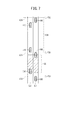
図7に示すように、追抜予測部80は、公知の手法を用いて、基準位置132(時刻t=T3)を起点とする、自車位置及び他車位置の時間変化をそれぞれ予測する。例えば、自車両100が他車両110を直近に追い抜く可能性がある場合、自車両100の先端位置と、他車両110の後端位置が一致する第1予測位置134(時刻t=T4)が新たに求められる。同様に、自車両100の後端位置と、他車両110の先端位置が一致する第2予測位置136(時刻t=T5)が新たに求められる。
As illustrated in FIG. 7, the overtaking
この場合、追抜区間138は、第1予測位置134から第2予測位置136までの走行区間に相当する。再予測の結果、新たな追抜区間138が制限区間120と重複しないため(ステップS6:YES)、今度はステップS7に進む。
In this case, the overtaking
ステップS7において、追抜実行判断部82は、他車両110を「追抜可能」であると判断し、自車両100の速度を元に戻して通常走行を再開する。これにより、自車両100は、追抜予測部80による予測結果に概ね従う走行挙動を示しながら第1レーンL1を直進する。
In step S <b> 7, the overtaking
ステップS8において、追抜実行判断部82は、他車両110の追い抜きを完了したか否かを確認する。追い抜きの完了をまだ確認していない場合(ステップS8:NO)、完了するまでステップS8に留まる。一方、時刻t=T5の付近にて追い抜きの完了を確認した場合(ステップS8:YES)、図3のフローチャートを終了する。
In step S8, the overtaking
<改良例>
続いて、上記した追抜実行の可否判断(図3のステップS6)の改良例について、図8A及び図8Bを参照しながら説明する。
<Improvement example>
Next, an improved example of the above-described determination on whether or not to perform additional extraction (step S6 in FIG. 3) will be described with reference to FIGS. 8A and 8B.
図8Aの例では、他車両110は、第2レーンL2上であって制限区間120内で停止している。この場合、追抜予測部80は、他車両110の車体が存在する区間を追抜区間128として予測する。そして、追抜実行判断部82は、区間の重なりを確認し、他車両110を一時的に「追抜不可」であると判断する。これにより、第1レーンL1上の自車両100は、一時的な減速動作を開始する。
In the example of FIG. 8A, the
このように、他車両認識部74は、他車両110が移動中又は停止中であることを認識し、走行制御部84は、他車両110が移動中又は停止中のいずれかにかかわらず、追抜区間128の全部又は一部が制限区間120と重複する場合に自車両100の速度を調整してもよい。停止中である他車両110が突如動き出すシーンを想定し、制限区間120内における意図しない追い抜きの発生を未然に防止することができる。
In this way, the other
図8Bの例では、図8Aの場合と同様に、他車両110は、第2レーンL2上であって制限区間120内で停止している。ただし、他車両110は、ハザードランプを灯火した状態にて駐車している。この場合、追抜予測部80は、他車両110の車体が存在する区間を追抜区間128として予測する。
In the example of FIG. 8B, as in the case of FIG. 8A, the
ところが、追抜実行判断部82は、区間の重なりがあるにもかかわらず、他車両110を「追抜可能」であると例外的に判断する。これにより、第1レーンL1上の自車両100は、一時的な減速動作を伴わずに通常走行を維持する。
However, the overtaking
このように、他車両認識部74は、停止中の他車両110が駐車状態であるか否かを認識し、走行制御部84は、他車両110が駐車状態である場合、追抜区間128の全部又は一部が制限区間120と重複するにもかかわらず、自車両100の速度を調整する走行制御を行わなくてもよい。自車両100が制限区間120を通過するまでの間に駐車状態の他車両110が動き出さないと推定することで、自車両100の速度を不必要に調整することなく円滑に追い抜くことができる。
As described above, the other
[車両制御装置10による効果]
以上のように、車両制御装置10は、自車両100の走行制御を少なくとも部分的に自動で行う装置であって、[1]自車両100が走行する第1レーンL1とは異なる第2レーンL2の前方にある他車両110を認識する他車両認識部74と、[2]自車両100の走行状態を示す自車両情報と、他車両110の走行状態を示す他車両情報との関係から、他車両110を追い抜く追抜区間128を予測する追抜予測部80と、[3]他車両110を追い抜く走行制御を行う走行制御部84と、を備える。そして、[4]走行制御部84は、予測された追抜区間128の全部又は一部が、追い抜きが制限される制限区間120と重複する場合、自車両100の速度を調整する走行制御を行う。
[Effects of vehicle control device 10]
As described above, the vehicle control device 10 is a device that at least partially automatically performs the travel control of the
また、この車両制御方法では、1つ又は複数のコンピュータが、[1]自車両100が走行する第1レーンL1とは異なる第2レーンL2の前方にある他車両110を認識し(ステップS1)、[2]自車両100の走行状態を示す自車両情報と、他車両110の走行状態を示す他車両情報との関係から、他車両110を追い抜く追抜区間128を予測し(ステップS5)、[3]他車両110を追い抜く走行制御を行い(ステップS7)、[4]予測された追抜区間128の全部又は一部が、追い抜きが制限される制限区間120と重複する場合(ステップS6:NO)、自車両100の速度を調整する走行制御を行う(ステップS9)。
In this vehicle control method, one or more computers recognize [1] the
このように、予測された追抜区間128の全部又は一部が、追い抜きが制限される制限区間120と重複する場合に自車両100の速度を調整するので、追抜区間128の位置を制限区間120と重複しないように移動可能となり、制限区間120内における他車両110の追い抜きの発生を防止することができる。
In this way, the speed of the
また、追抜予測部80は、自車両100の速度の調整の開始時点(時刻t=T0)から所定時間が経過した後、又は、自車両100の速度の調整の開始位置(減速開始位置130)から所定距離を走行した後に新たな追抜区間138を予測し、走行制御部84は、予測された新たな追抜区間138が制限区間120と重複しない場合、他車両110を追い抜く走行制御を行ってもよい。これにより、追い抜きのリトライ機能を実現可能となり、当初予定していた追い抜きが自動的にかつ円滑に行われる。
Further, the overtaking
[補足]
なお、この発明は、上述した実施形態に限定されるものではなく、この発明の主旨を逸脱しない範囲で自由に変更できることは勿論である。或いは、技術的に矛盾が生じない範囲で各々の構成を任意に組み合わせてもよい。
[Supplement]
In addition, this invention is not limited to embodiment mentioned above, Of course, it can change freely in the range which does not deviate from the main point of this invention. Or you may combine each structure arbitrarily in the range which does not produce technical contradiction.
上述した実施形態では、自車両100を減速させる調整を行う例を示したが、これとは反対に自車両100を加速させる調整を行ってもよい。つまり、追抜区間138と制限区間120が重複しない状況を作り出すことが可能であれば、走行制御に関する任意の調整方法を採用してもよい。
In the above-described embodiment, an example in which the adjustment for decelerating the
10…車両制御装置 12…制御系装置群
14…入力系装置群 16…出力系装置群
18…外界センサ 20…通信装置
22…地図情報DB 24…ナビゲーション装置
26…車両センサ 40…駆動力出力装置
42…操舵装置 44…制動装置
46…報知装置 50…演算装置
52…記憶装置 60…外界認識部
62…自車位置認識部 64…行動計画作成部
66…軌道生成部 68…車両制御部
70…運転モード切替部 72…特定地点認識部
74…他車両認識部 76…外界状態認識部
78…制限区間設定部 80…追抜予測部
82…追抜実行判断部 84…走行制御部
86…報知制御部 100…自車両
102…走行予定経路 104、106…道路
108…交差点 110…他車両
112…信号機 114、116…横断歩道
118…認識位置 120…制限区間
122、132…基準位置 124、134…第1予測位置
128、138…追抜区間 130…減速開始位置
L1…第1レーン L2…第2レーン
DESCRIPTION OF SYMBOLS 10 ... Vehicle control apparatus 12 ... Control system apparatus group 14 ... Input system apparatus group 16 ... Output system apparatus group 18 ... External sensor 20 ... Communication apparatus 22 ... Map information DB 24 ... Navigation apparatus 26 ... Vehicle sensor 40 ... Driving force output apparatus DESCRIPTION OF SYMBOLS 42 ... Steering device 44 ... Braking device 46 ...
Claims (3)
前記自車両が走行するレーンとは異なるレーンの前方にある他車両を認識する他車両認識部と、
前記自車両の走行状態を示す自車両情報と、前記他車両の走行状態を示す他車両情報との関係から、前記他車両を追い抜く追抜区間を予測する追抜予測部と、
前記他車両を追い抜く走行制御を行う走行制御部と、
を備え、
前記走行制御部は、前記追抜予測部により予測された前記追抜区間の全部又は一部が、追い抜きが制限される制限区間と重複する場合、前記自車両の速度を調整する走行制御を行い、
前記他車両認識部は、前記他車両が移動中又は停止中であることを認識し、
前記走行制御部は、前記他車両が移動中又は停止中のいずれかにかかわらず、前記追抜区間の全部又は一部が前記制限区間と重複する場合に前記自車両の速度を調整する走行制御を行い、
前記他車両認識部は、停止中の前記他車両が駐車状態であるか否かを認識し、
前記走行制御部は、前記他車両が駐車状態である場合、前記追抜区間の全部又は一部が前記制限区間と重複するにもかかわらず、前記自車両の速度を調整する走行制御を行わない
ことを特徴とする車両制御装置。 A vehicle control device that performs at least partially automatic driving control of the host vehicle,
An other vehicle recognition unit for recognizing another vehicle in front of a lane different from the lane on which the host vehicle travels
An overtaking prediction unit that predicts an overtaking section that overtakes the other vehicle from the relationship between the own vehicle information indicating the running state of the own vehicle and the other vehicle information indicating the running state of the other vehicle;
A travel control unit that performs travel control to overtake the other vehicle;
With
The travel control unit performs travel control to adjust the speed of the host vehicle when all or a part of the overtaking section predicted by the overtaking prediction unit overlaps a restricted section where overtaking is restricted. Yes,
The other vehicle recognition unit recognizes that the other vehicle is moving or stopped,
The travel control unit adjusts the speed of the host vehicle when all or a part of the overtaking section overlaps with the restricted section regardless of whether the other vehicle is moving or stopped. And
The other vehicle recognition unit recognizes whether the other vehicle being stopped is in a parked state,
When the other vehicle is in a parked state, the travel control unit does not perform travel control for adjusting the speed of the host vehicle even though all or part of the overtaking section overlaps with the restricted section. The vehicle control apparatus characterized by the above-mentioned.
前記追抜予測部は、前記自車両の速度の調整の開始時点から所定時間が経過した後、又は、前記自車両の速度の調整の開始位置から所定距離を走行した後に新たな追抜区間を予測し、
前記走行制御部は、予測された前記新たな追抜区間が前記制限区間と重複しない場合、前記他車両を追い抜く走行制御を行う
ことを特徴とする車両制御装置。 The vehicle control device according to claim 1,
The overtaking predicting unit sets a new overtaking section after a predetermined time has elapsed since the start of the speed adjustment of the own vehicle or after traveling a predetermined distance from the start position of the speed adjustment of the own vehicle. Predict,
The vehicle control device, wherein the traveling control unit performs traveling control to overtake the other vehicle when the predicted new overtaking section does not overlap with the restricted section.
前記制限区間は、踏切を含む走行区間、交差点を含む走行区間、横断歩道を含む走行区間、自転車横断帯を含む走行区間、及び幅員が狭い走行区間のうち少なくとも1つの走行区間であることを特徴とする車両制御装置。 In the vehicle control device according to claim 1 or 2,
The restricted section is at least one of a traveling section including a crossing, a traveling section including an intersection, a traveling section including a pedestrian crossing, a traveling section including a bicycle crossing zone, and a traveling section having a narrow width. A vehicle control device.
Priority Applications (3)
| Application Number | Priority Date | Filing Date | Title |
|---|---|---|---|
| JP2017198160A JP6600671B2 (en) | 2017-10-12 | 2017-10-12 | Vehicle control device |
| US16/156,133 US10821980B2 (en) | 2017-10-12 | 2018-10-10 | Vehicle control device |
| CN201811190060.9A CN109664883B (en) | 2017-10-12 | 2018-10-12 | Vehicle control device |
Applications Claiming Priority (1)
| Application Number | Priority Date | Filing Date | Title |
|---|---|---|---|
| JP2017198160A JP6600671B2 (en) | 2017-10-12 | 2017-10-12 | Vehicle control device |
Publications (2)
| Publication Number | Publication Date |
|---|---|
| JP2019073042A JP2019073042A (en) | 2019-05-16 |
| JP6600671B2 true JP6600671B2 (en) | 2019-10-30 |
Family
ID=66097256
Family Applications (1)
| Application Number | Title | Priority Date | Filing Date |
|---|---|---|---|
| JP2017198160A Active JP6600671B2 (en) | 2017-10-12 | 2017-10-12 | Vehicle control device |
Country Status (3)
| Country | Link |
|---|---|
| US (1) | US10821980B2 (en) |
| JP (1) | JP6600671B2 (en) |
| CN (1) | CN109664883B (en) |
Families Citing this family (6)
| Publication number | Priority date | Publication date | Assignee | Title |
|---|---|---|---|---|
| JP6617692B2 (en) | 2016-12-07 | 2019-12-11 | 株式会社デンソー | Driving change control device and driving change control method |
| JP7318332B2 (en) * | 2019-06-13 | 2023-08-01 | 株式会社ジェイテクト | Crosswind effect estimation device and vehicle control device |
| JP7049391B2 (en) * | 2019-07-09 | 2022-04-06 | 本田技研工業株式会社 | Vehicle control devices, vehicle control methods, and programs |
| CN112208531B (en) * | 2019-07-09 | 2024-04-30 | 本田技研工业株式会社 | Vehicle control device, vehicle control method and storage medium |
| JP7082095B2 (en) * | 2019-07-12 | 2022-06-07 | 本田技研工業株式会社 | Vehicle control devices, vehicle control methods, and programs |
| JP7078909B2 (en) * | 2019-12-19 | 2022-06-01 | トヨタ自動車株式会社 | Vehicle control device and computer program for vehicle control |
Family Cites Families (21)
| Publication number | Priority date | Publication date | Assignee | Title |
|---|---|---|---|---|
| DE10324725A1 (en) * | 2003-05-30 | 2004-12-16 | Wabco Gmbh & Co.Ohg | Procedure for regulating overtaking in a non-passing lane |
| EP1652128B1 (en) * | 2003-07-07 | 2014-05-14 | Insurance Services Office, Inc. | Traffic information system |
| EP1495932B1 (en) * | 2003-07-07 | 2007-08-29 | Nissan Motor Company, Limited | Lane departure prevention apparatus |
| CN103503044B (en) * | 2011-04-21 | 2015-10-21 | 三菱电机株式会社 | Driving supporting device |
| DE102012208740A1 (en) * | 2012-05-24 | 2013-11-28 | Bayerische Motoren Werke Aktiengesellschaft | Detection of directional lanes |
| EP3056405B1 (en) * | 2013-10-11 | 2018-01-17 | Nissan Motor Co., Ltd | Travel control device and travel control method |
| EP2955077B1 (en) * | 2014-06-10 | 2022-08-17 | Volvo Car Corporation | Overtake assessment system and autonomous vehicle with an overtake assessment arrangement |
| JP6103716B2 (en) * | 2014-06-17 | 2017-03-29 | 富士重工業株式会社 | Vehicle travel control device |
| JP6031066B2 (en) * | 2014-06-17 | 2016-11-24 | 富士重工業株式会社 | Vehicle travel control device |
| JP2016002893A (en) * | 2014-06-17 | 2016-01-12 | 富士重工業株式会社 | Travel control device of vehicle |
| JP2016168985A (en) * | 2015-03-16 | 2016-09-23 | トヨタ自動車株式会社 | Travel control device |
| JP6394497B2 (en) * | 2015-05-25 | 2018-09-26 | トヨタ自動車株式会社 | Automatic vehicle driving system |
| JP6565615B2 (en) | 2015-11-06 | 2019-08-28 | 株式会社デンソー | Vehicle control device |
| KR101788183B1 (en) * | 2015-12-28 | 2017-10-20 | 현대자동차주식회사 | Vehicle and controlling method for the vehicle |
| JP6323473B2 (en) * | 2016-02-25 | 2018-05-16 | トヨタ自動車株式会社 | Travel control device |
| US20190084561A1 (en) * | 2016-03-15 | 2019-03-21 | Honda Motor Co., Ltd. | Vehicle control apparatus, vehicle control method, and vehicle control program |
| DE102016208000A1 (en) * | 2016-05-10 | 2017-11-16 | Volkswagen Aktiengesellschaft | Motor vehicle control device and method for operating the control device for the autonomous guidance of a motor vehicle |
| DE102016005884A1 (en) * | 2016-05-12 | 2017-11-16 | Adam Opel Ag | Driver assistance system |
| CN109643496B (en) * | 2016-09-21 | 2021-08-20 | 苹果公司 | vehicle control system |
| US10513268B2 (en) * | 2017-04-07 | 2019-12-24 | Steering Solutions Ip Holding Corporation | Vehicle safety system |
| US10606277B2 (en) * | 2017-09-18 | 2020-03-31 | Baidu Usa Llc | Speed optimization based on constrained smoothing spline for autonomous driving vehicles |
-
2017
- 2017-10-12 JP JP2017198160A patent/JP6600671B2/en active Active
-
2018
- 2018-10-10 US US16/156,133 patent/US10821980B2/en not_active Expired - Fee Related
- 2018-10-12 CN CN201811190060.9A patent/CN109664883B/en not_active Expired - Fee Related
Also Published As
| Publication number | Publication date |
|---|---|
| JP2019073042A (en) | 2019-05-16 |
| US20190111931A1 (en) | 2019-04-18 |
| US10821980B2 (en) | 2020-11-03 |
| CN109664883B (en) | 2021-12-10 |
| CN109664883A (en) | 2019-04-23 |
Similar Documents
| Publication | Publication Date | Title |
|---|---|---|
| JP6606148B2 (en) | Vehicle control device | |
| JP6677822B2 (en) | Vehicle control device | |
| JP7032170B2 (en) | Vehicle control device | |
| JP6600671B2 (en) | Vehicle control device | |
| JP6650904B2 (en) | Vehicle control device | |
| JP6812568B2 (en) | Vehicle control device | |
| JP6817413B2 (en) | Vehicle control device | |
| JP6633588B2 (en) | Vehicle control device | |
| US10948303B2 (en) | Vehicle control device | |
| JP6985176B2 (en) | Vehicle control device | |
| US10807609B2 (en) | Vehicle control device | |
| JP6880222B2 (en) | Vehicle control device | |
| US20190256098A1 (en) | Vehicle control device | |
| EP4137378B1 (en) | Travel assistance method and travel assistance device | |
| CN116547182B (en) | Automatic driving control method and automatic driving control device | |
| JP2019219885A (en) | Driving support method and driving support device | |
| JP2020045039A (en) | Vehicle control method and vehicle control device | |
| JP2018055321A (en) | Driving support method and driving support device | |
| JP7471150B2 (en) | Driving support method and driving support device | |
| JP7393258B2 (en) | Control device and vehicle | |
| JP2019045985A (en) | Vehicle control device, vehicle, vehicle control method, and program | |
| RU2789800C1 (en) | Movement assistance method and movement assistance device | |
| JP7516232B2 (en) | Vehicle driving control method and driving control device | |
| WO2024111192A1 (en) | Driving assistance device | |
| JP2021183450A (en) | Travel support method and travel support apparatus for vehicle |
Legal Events
| Date | Code | Title | Description |
|---|---|---|---|
| A621 | Written request for application examination |
Free format text: JAPANESE INTERMEDIATE CODE: A621 Effective date: 20180529 |
|
| A131 | Notification of reasons for refusal |
Free format text: JAPANESE INTERMEDIATE CODE: A131 Effective date: 20190514 |
|
| A521 | Request for written amendment filed |
Free format text: JAPANESE INTERMEDIATE CODE: A523 Effective date: 20190607 |
|
| TRDD | Decision of grant or rejection written | ||
| A01 | Written decision to grant a patent or to grant a registration (utility model) |
Free format text: JAPANESE INTERMEDIATE CODE: A01 Effective date: 20191001 |
|
| A61 | First payment of annual fees (during grant procedure) |
Free format text: JAPANESE INTERMEDIATE CODE: A61 Effective date: 20191007 |
|
| R150 | Certificate of patent or registration of utility model |
Ref document number: 6600671 Country of ref document: JP Free format text: JAPANESE INTERMEDIATE CODE: R150 |