JPWO2010113550A1 - Endoscope - Google Patents
Endoscope Download PDFInfo
- Publication number
- JPWO2010113550A1 JPWO2010113550A1 JP2010538672A JP2010538672A JPWO2010113550A1 JP WO2010113550 A1 JPWO2010113550 A1 JP WO2010113550A1 JP 2010538672 A JP2010538672 A JP 2010538672A JP 2010538672 A JP2010538672 A JP 2010538672A JP WO2010113550 A1 JPWO2010113550 A1 JP WO2010113550A1
- Authority
- JP
- Japan
- Prior art keywords
- optical system
- illumination
- light guide
- plano
- illumination optical
- Prior art date
- Legal status (The legal status is an assumption and is not a legal conclusion. Google has not performed a legal analysis and makes no representation as to the accuracy of the status listed.)
- Granted
Links
Images


Classifications
-
- A—HUMAN NECESSITIES
- A61—MEDICAL OR VETERINARY SCIENCE; HYGIENE
- A61B—DIAGNOSIS; SURGERY; IDENTIFICATION
- A61B1/00—Instruments for performing medical examinations of the interior of cavities or tubes of the body by visual or photographical inspection, e.g. endoscopes; Illuminating arrangements therefor
- A61B1/04—Instruments for performing medical examinations of the interior of cavities or tubes of the body by visual or photographical inspection, e.g. endoscopes; Illuminating arrangements therefor combined with photographic or television appliances
- A61B1/05—Instruments for performing medical examinations of the interior of cavities or tubes of the body by visual or photographical inspection, e.g. endoscopes; Illuminating arrangements therefor combined with photographic or television appliances characterised by the image sensor, e.g. camera, being in the distal end portion
-
- A—HUMAN NECESSITIES
- A61—MEDICAL OR VETERINARY SCIENCE; HYGIENE
- A61B—DIAGNOSIS; SURGERY; IDENTIFICATION
- A61B1/00—Instruments for performing medical examinations of the interior of cavities or tubes of the body by visual or photographical inspection, e.g. endoscopes; Illuminating arrangements therefor
- A61B1/00064—Constructional details of the endoscope body
- A61B1/00071—Insertion part of the endoscope body
- A61B1/0008—Insertion part of the endoscope body characterised by distal tip features
- A61B1/00096—Optical elements
-
- A—HUMAN NECESSITIES
- A61—MEDICAL OR VETERINARY SCIENCE; HYGIENE
- A61B—DIAGNOSIS; SURGERY; IDENTIFICATION
- A61B1/00—Instruments for performing medical examinations of the interior of cavities or tubes of the body by visual or photographical inspection, e.g. endoscopes; Illuminating arrangements therefor
- A61B1/06—Instruments for performing medical examinations of the interior of cavities or tubes of the body by visual or photographical inspection, e.g. endoscopes; Illuminating arrangements therefor with illuminating arrangements
- A61B1/0625—Instruments for performing medical examinations of the interior of cavities or tubes of the body by visual or photographical inspection, e.g. endoscopes; Illuminating arrangements therefor with illuminating arrangements for multiple fixed illumination angles
-
- A—HUMAN NECESSITIES
- A61—MEDICAL OR VETERINARY SCIENCE; HYGIENE
- A61B—DIAGNOSIS; SURGERY; IDENTIFICATION
- A61B1/00—Instruments for performing medical examinations of the interior of cavities or tubes of the body by visual or photographical inspection, e.g. endoscopes; Illuminating arrangements therefor
- A61B1/06—Instruments for performing medical examinations of the interior of cavities or tubes of the body by visual or photographical inspection, e.g. endoscopes; Illuminating arrangements therefor with illuminating arrangements
- A61B1/07—Instruments for performing medical examinations of the interior of cavities or tubes of the body by visual or photographical inspection, e.g. endoscopes; Illuminating arrangements therefor with illuminating arrangements using light-conductive means, e.g. optical fibres
Landscapes
- Health & Medical Sciences (AREA)
- Life Sciences & Earth Sciences (AREA)
- Surgery (AREA)
- Biomedical Technology (AREA)
- Medical Informatics (AREA)
- Optics & Photonics (AREA)
- Pathology (AREA)
- Radiology & Medical Imaging (AREA)
- Biophysics (AREA)
- Engineering & Computer Science (AREA)
- Physics & Mathematics (AREA)
- Heart & Thoracic Surgery (AREA)
- Nuclear Medicine, Radiotherapy & Molecular Imaging (AREA)
- Molecular Biology (AREA)
- Animal Behavior & Ethology (AREA)
- General Health & Medical Sciences (AREA)
- Public Health (AREA)
- Veterinary Medicine (AREA)
- Endoscopes (AREA)
- Instruments For Viewing The Inside Of Hollow Bodies (AREA)
Abstract
照明光の配光性を向上させて良好な観察視野を確保しつつ、挿入部の先端部を小型化して挿入性を向上することができる内視鏡を提供する。先端部(11)を有するチューブ状の挿入部(13)と、挿入部(13)内に収容され先端部(11)に向かって照明光を導光するライトガイド(15)と、挿入部(13)の先端部(11)に配置され、ライトガイド(15)により導光された照明光を照射する平凹レンズ(17)および平凹レンズ(17)により照明された観察領域(A)からの光を集光する対物レンズ(19)とを備え、ライトガイド(15)の平凹レンズ(17)に対向する端部が、対物レンズ(19)の光軸(L)と略平行に延び、先端部(11)の肩部(21)および肩部(21)に位置する平凹レンズ(17)の外面が、先端に向かって先細になるように傾斜している内視鏡(1)を採用する。Provided is an endoscope that can improve the light distribution of illumination light and secure a good observation field, and can reduce the tip of the insertion portion to improve the insertion property. A tube-shaped insertion portion (13) having a distal end portion (11), a light guide (15) that is accommodated in the insertion portion (13) and guides illumination light toward the distal end portion (11), and an insertion portion ( The light from the observation area (A) illuminated by the plano-concave lens (17) and the plano-concave lens (17), which is arranged at the tip (11) of 13) and irradiates the illumination light guided by the light guide (15) An end of the light guide (15) facing the plano-concave lens (17) extends substantially parallel to the optical axis (L) of the objective lens (19), An endoscope (1) in which the outer surface of the shoulder (21) of (11) and the plano-concave lens (17) located at the shoulder (21) is inclined so as to taper toward the tip is adopted.
Description
本発明は、内視鏡に関するものである。 The present invention relates to an endoscope.
従来、挿入部の先端に照明光を導光するライトガイドと撮像素子とを備え、このライトガイドを撮像素子の光軸に対して傾斜させた内視鏡が知られている(例えば、特許文献1参照)。この内視鏡は、傾斜させたライトガイドから挿入部の挿入方向前方および側方に対して照明を行うことで、観察視野を広く確保することを目的としている。 2. Description of the Related Art Conventionally, an endoscope is known that includes a light guide that guides illumination light at the distal end of an insertion portion and an imaging device, and the light guide is inclined with respect to the optical axis of the imaging device (for example, Patent Documents). 1). This endoscope is intended to ensure a wide observation field of view by illuminating the front and side of the insertion portion in the insertion direction from an inclined light guide.
しかしながら、特許文献1に開示されている技術によれば、ライトガイドを撮像素子の光軸に対して傾斜させるため、挿入部の先端部が大きくなってしまい、体腔内や機器内部等への挿入性を阻害してしまうという不都合があった。
However, according to the technique disclosed in
特許文献2および3に開示されている技術によれば、照明光の配光性を向上させるために挿入部の先端部に凹レンズまたは凸レンズを設けているが、組み立て時の位置決め精度の向上、接着剤の流れ込み防止といった組み立て性の向上のために、挿入部の先端部に爪が設けられている。この爪による照射範囲のけられを防ぐために照明レンズの外径を大きくすることで、さらに挿入部の先端部が大きくなってしまい、体腔内や機器内部等への挿入性を低下させてしまうという不都合があった。 According to the techniques disclosed in Patent Documents 2 and 3, a concave lens or a convex lens is provided at the distal end portion of the insertion portion in order to improve the light distribution of illumination light. A claw is provided at the distal end portion of the insertion portion in order to improve the assemblability such as prevention of agent flow. Increasing the outer diameter of the illumination lens in order to prevent the irradiation range from being crushed by the nail further increases the distal end of the insertion portion, thereby reducing the ability to insert into the body cavity or inside the device. There was an inconvenience.
本発明は、上記事情に鑑みてなされたもので、照明光の配光性を向上させて良好な観察視野を確保しつつ、挿入部の先端部を小型化して挿入性を向上することができる内視鏡を提供することを目的とする。 The present invention has been made in view of the above circumstances, and it is possible to improve the insertability by reducing the tip of the insertion portion while improving the light distribution of the illumination light and ensuring a good observation field of view. An object is to provide an endoscope.
上記目的を達成するために、本発明は以下の手段を採用する。
本発明は、先端部を有するチューブ状の挿入部と、該挿入部内に収容され前記先端部に向かって照明光を導光する導光部材と、前記挿入部の前記先端部に配置され、前記導光部材により導光された照明光を照射する照明光学系および該照明光学系により照明された領域からの光を集光する対物光学系とを備え、前記導光部材の前記照明光学系に対向する端部が、前記対物光学系の光軸と略平行に延び、前記先端部の肩部および該肩部に位置する前記照明光学系の外面が、先端に向かって先細になるように傾斜している内視鏡を採用する。In order to achieve the above object, the present invention employs the following means.
The present invention includes a tube-shaped insertion portion having a distal end portion, a light guide member that is accommodated in the insertion portion and guides illumination light toward the distal end portion, and is disposed at the distal end portion of the insertion portion, An illumination optical system that irradiates illumination light guided by the light guide member, and an objective optical system that condenses light from a region illuminated by the illumination optical system, the illumination optical system of the light guide member Opposing ends extend substantially parallel to the optical axis of the objective optical system, and the shoulder of the tip and the outer surface of the illumination optical system located on the shoulder are inclined so as to taper toward the tip. The endoscope which is used is adopted.
本発明によれば、挿入部の先端部の肩部および該肩部に位置する照明光学系の外面が、先端に向かって先細になるように傾斜しているため、体腔内や機器内部等への挿入性を向上することができる。また、例えば凹レンズ等の照明光学系の外面が、先端に向かって先細になるように傾斜しているため、導光部材により導光された照明光を、例えば対物レンズ等の対物光学系の光軸に向かう方向に屈折して照射することができる。これにより、良好な観察視野を確保した上で、照明された領域を対物光学系により観察することができ、その観察精度を向上することができる。 According to the present invention, since the shoulder portion of the distal end portion of the insertion portion and the outer surface of the illumination optical system positioned on the shoulder portion are inclined so as to taper toward the distal end, the inside of the body cavity, the inside of the device, or the like Insertability can be improved. Further, since the outer surface of the illumination optical system such as a concave lens is inclined so as to taper toward the tip, the illumination light guided by the light guide member is used as the light of the objective optical system such as an objective lens. Irradiation can be performed with refraction in the direction toward the axis. Thereby, after ensuring a favorable observation visual field, the illuminated region can be observed by the objective optical system, and the observation accuracy can be improved.
上記発明において、前記挿入部の少なくとも先端部と、前記照明光学系とが、不透明な樹脂と透明な樹脂とを用いた2色成形により一体成形されていることとしてもよい。
2色成形により挿入部の先端部と照明光学系とを一体成形することで、照明光学系の組み立て性向上のための爪を挿入部の先端部に設ける必要性を排除することができる。これにより、挿入部の先端を小さくするとともに、その先端形状を突起物のない流線型とすることができ、体腔内や機器内部等への挿入性を向上することができる。In the above invention, at least the distal end portion of the insertion portion and the illumination optical system may be integrally formed by two-color molding using an opaque resin and a transparent resin.
By integrally molding the distal end portion of the insertion portion and the illumination optical system by two-color molding, it is possible to eliminate the necessity of providing a claw for improving the assembly of the illumination optical system at the distal end portion of the insertion portion. Thereby, while making the front-end | tip of an insertion part small, the front-end | tip shape can be made into a streamline type without a protrusion, and the insertion property in a body cavity, the inside of an apparatus, etc. can be improved.
上記発明において、前記照明光学系を2つ備え、該2つの照明光学系が、前記対物光学系の光軸を通過する平面に対して略鏡面対称となる位置に配置されていることとしてもよい。
このようにすることで、2つの照明光学系からの照明光を、対物光学系の光軸に向かう方向に均等に照射することができ、良好な観察視野を確保することが可能となる。In the above invention, the two illumination optical systems may be provided, and the two illumination optical systems may be arranged at positions that are substantially mirror-symmetric with respect to a plane that passes through the optical axis of the objective optical system. .
By doing in this way, the illumination light from two illumination optical systems can be equally irradiated in the direction which goes to the optical axis of an objective optical system, and it becomes possible to ensure a favorable observation visual field.
上記発明において、前記対物光学系の光軸方向から見たときに、前記照明光学系の外面の略中央における前記傾斜の方向と、前記対物光学系による観察視野の対角方向とのなす角が30°以下であることとしてもよい。
このようにすることで、照明光学系からの照明光を対物光学系の光軸に向かう方向に向けて効率的に照射することができ、良好な観察視野を確保することが可能となる。In the above invention, when viewed from the optical axis direction of the objective optical system, an angle formed by the direction of inclination at the approximate center of the outer surface of the illumination optical system and the diagonal direction of the observation field of view by the objective optical system is It is good also as being 30 degrees or less.
By doing in this way, the illumination light from an illumination optical system can be efficiently irradiated toward the direction toward the optical axis of an objective optical system, and a favorable observation visual field can be ensured.
上記発明において、前記対物光学系の光軸方向から見たときに、前記照明光学系の外面の略中央における前記傾斜の方向と、前記対物光学系の中心と前記照明光学系との中心とを通る直線とのなす角が30°以下であることとしてもよい。
このようにすることで、照明光学系からの照明光を対物光学系の光軸に向かう方向に効率的に照射することができ、良好な観察視野を確保することが可能となる。In the above invention, when viewed from the optical axis direction of the objective optical system, the direction of inclination at the approximate center of the outer surface of the illumination optical system, and the center of the objective optical system and the center of the illumination optical system The angle formed by the straight line that passes through may be 30 ° or less.
By doing so, it is possible to efficiently irradiate illumination light from the illumination optical system in a direction toward the optical axis of the objective optical system, and to secure a good observation field.
上記発明において、前記照明光学系は、外面が平面且つ内面が曲面で形成された平凹レンズであり、該平凹レンズは、前記照明光学系の外面の略中央において、前記傾斜の方向における前記曲面の曲率が、前記傾斜と直交する方向における前記曲面の曲率よりも大きく形成されていることとしてもよい。
このようにすることで、照明光学系からの照明光を対物光学系の光軸に向かう方向に大きく拡散させて照射することができ、観察視野内を効率良く照明することができるため、良好な観察視野を確保することが可能となる。In the above invention, the illumination optical system is a plano-concave lens having a flat outer surface and a curved inner surface, and the plano-concave lens has the curved surface in the direction of inclination at the approximate center of the outer surface of the illumination optical system. The curvature may be larger than the curvature of the curved surface in the direction orthogonal to the inclination.
By doing so, the illumination light from the illumination optical system can be diffused and irradiated in the direction toward the optical axis of the objective optical system, and the observation field can be efficiently illuminated. An observation field of view can be secured.
上記発明において、前記照明光学系が内面側において周方向に突起する凸部を有し、前記挿入部が前記凸部と嵌合する凹部または段差部を有することとしてもよい。
このようにすることで、スコープ先端の外径を大きくすることなく、容易な構成で照明光学系の位置決めを行うことができる。また、2色成形の場合には2種類の樹脂の接合強度を高めることができる。これにより、爪を挿入部に設ける必要性を排除して、挿入部の先端を小さくすることができ、体腔内や機器内部等への挿入性を向上することができる。In the above invention, the illumination optical system may have a convex portion that protrudes in the circumferential direction on the inner surface side, and the insertion portion may have a concave portion or a step portion that fits into the convex portion.
In this way, the illumination optical system can be positioned with an easy configuration without increasing the outer diameter of the scope tip. In the case of two-color molding, the bonding strength of two types of resins can be increased. Thereby, it is possible to eliminate the necessity of providing the nail in the insertion portion, to reduce the tip of the insertion portion, and to improve the insertability into the body cavity or the inside of the device.
本発明によれば、照明光の配光性を向上させて良好な観察視野を確保しつつ、挿入部の先端部を小型化して挿入性を向上することができるという効果を奏する。 According to the present invention, there is an effect that the insertion property can be improved by reducing the size of the distal end portion of the insertion portion while improving the light distribution property of the illumination light and ensuring a good observation visual field.
以下、本発明の一実施形態に係る内視鏡について図面を参照して説明する。
本実施形態に係る内視鏡1は、チューブ状の形状を有し体腔内や機器内部等に挿入されて内部の画像を取得する挿入部13と、挿入部13に照明光を入射させる光源装置(図示略)と、挿入部13により取得された画像に画像処理を施す画像処理部(図示略)と、画像処理された画像を表示する表示部(図示略)とを主な構成要素として備えている。Hereinafter, an endoscope according to an embodiment of the present invention will be described with reference to the drawings.
An
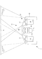
図1は、本実施形態に係る挿入部13の概略構成を示す模式図である。
図1に示すように、挿入部13は、挿入部13内に収容されたライトガイド(導光部材)15と、挿入部13の先端部11に配置された対物レンズ(対物光学系)19と、挿入部13の先端部11において対物レンズ19よりも半径方向外方に配置された一対の平凹レンズ(照明光学系)17とを備えている。また、挿入部13の先端部11には肩部21が形成されており、肩部21は先端に向かって先細になるように傾斜している。FIG. 1 is a schematic diagram illustrating a schematic configuration of the
As shown in FIG. 1, the
ライトガイド15は、例えば光ファイバであり、基端部が図示しない光源装置に接続され、該光源装置から射出されて基端部に入射させた照明光を、先端部11に向かって導光するようになっている。ライトガイド15の平凹レンズ17に対向する端部は、対物レンズ19の光軸Lと略平行に延びている。
The
平凹レンズ17は、外面が平面、且つ、内面が曲面で形成された凹レンズであり、先端部11が対向する観察領域Aに対して、ライトガイド15により導光された照明光を拡散して照射するようになっている。
The plano-
挿入部13の先端部11と、平凹レンズ17とは、不透明な樹脂と透明な樹脂とを用いた2色成形により一体成形されている。具体的には、平凹レンズ17は、挿入部13の半径方向内方に近づくに従って肉厚が大きくなるように形成され、肩部21に位置する外面が、先端に向かって先細になるように傾斜する形状とされている。これにより、図1に示すように、ライトガイド15により導光された照明光を、凹面で拡散した後、対物レンズ19の光軸Lに向かう方向に屈折して照射するようになっている。
The
対物レンズ19は、平凹レンズ17により照明された観察領域Aからの光を集光するようになっている。対物レンズ19により集光された光は、図示しない撮像素子上に結像され、電気信号に変換されて図示しない画像処理部に送られるようになっている。
The
2つの平凹レンズ17は、挿入部13の軸方向において、対物レンズ19の先端よりも基端側に位置して設けられている。これは、対物レンズ19が広い視野角を有するため周囲の光を受け易いためである。すなわち、2つの平凹レンズ17からの照明光が、対物レンズ19に直接入射して観察画像にフレアが生じてしまう場合がある。このフレアを防止するために、対物レンズ19よりも基端側に2つの平凹レンズ17が設けられている。
The two plano-
図2は、挿入部13の先端側から見た場合の正面図である。
図2に示すように、挿入部13の先端部11には、対物レンズ19と、一対の平凹レンズ17とが設けられている。なお、ここでは説明を省略するが、挿入部13の先端部11には、対物レンズ19および平凹レンズ17の他に、処置具挿通チャンネル開口(図示略)と、水切りをする送水ノズル(図示略)と、被検者等の患部の血液、粘液等を洗浄する前方送水ノズル(図示略)とが設けられる場合もある。FIG. 2 is a front view when viewed from the distal end side of the
As shown in FIG. 2, the
挿入部13の先端部11には、一対の平凹レンズ17が、対物レンズ19の光軸Lを中心として、観察領域内の照度が均一になるように配置されている。具体的には、2つの平凹レンズ17が、対物レンズ19の光軸Lを通過する平面に対して略鏡面対称となる位置に配置されている。また、2つの平凹レンズ17は、それぞれ、挿入部13の先端側から見た場合に、対物レンズ19を中心として対称面から45°から135°の範囲と、−45°から−135°の範囲に配置されている。これにより、少ない照明手段でも観察領域内の照度配分を良好にしつつ、挿入部13の細径化を図っている。
A pair of plano-
図3Aから図3Cに示すように、2つの平凹レンズ17は、その傾斜の方向が決められている。ここで、図3Aは挿入部13の先端側から見た場合の正面図、図3Bは対物レンズ19による観察視野、図3Cは平凹レンズ17の外面の略中央における傾斜の方向とライトガイド15の光軸とで規定される断面の縦断面図を示している。
As shown in FIGS. 3A to 3C, the direction of inclination of the two plano-
具体的には、2つの平凹レンズ17は、対物レンズ19の光軸方向から見たときに、平凹レンズ17の外面の略中央における傾斜の方向、すなわち、図3Aおよび図3Cにおける矢印の方向と、対物レンズ19による観察視野の対角方向、すなわち、図3Bにおける矢印の方向とのなす角が30°以下とされている。
このようにすることで、平凹レンズ17からの照明光を、観察距離が近いときも遠いときも、観察領域内の照度配分が良好になるように効率的に照射することができ、良好な観察視野を確保することが可能となる。Specifically, when viewed from the optical axis direction of the
By doing in this way, the illumination light from the plano-
上記構成を有する内視鏡1の作用について以下に説明する。
図示しない光源装置から射出された照明光は、ライトガイド15の基端部に入射し、ライトガイド15内を内面反射して、挿入部13の先端部11に配置された一対の平凹レンズ17に導光される。一対の平凹レンズ17に導光された照明光は、平凹レンズ17の作用により光線が拡散されるとともに、対物レンズ19の光軸Lに向かう方向に屈折して照射される。これにより、対物レンズ19の光軸方向の観察領域Aが照明される。この際、それぞれの平凹レンズ17の照射方向が異なるため、これらレンズからの光を重ね合わせることで、図1に示すように先端部11から近い領域を良好に照明できるとともに、図7に示すように先端部11から遠い領域では広い照射範囲を得ることができる。The operation of the
Illumination light emitted from a light source device (not shown) is incident on the proximal end portion of the
観察領域Aからの反射光は、対物レンズ19により集光され、図示しない撮像素子により結像される。その後、電気信号に変換されて画像処理部により画像処理が施され、表示部に観察画像として表示される。
The reflected light from the observation area A is collected by the
比較例として、従来の内視鏡による観察領域Aの照明状態について、図10を用いて説明する。
図10に示すように、従来の内視鏡10では、平凹レンズ18からの照明光は、対物レンズ19の光軸Lと平行に射出されるため、挿入部14の先端部と観察領域Aとの距離が近い場合には観察領域Aを良好に照明することができない。また、それぞれの平凹レンズ18の照射方向は同じであるため、図10に示すように先端部と観察領域Aとの距離が遠い場合には、照射範囲が広がるような効果は得られない。
さらに、平凹レンズ18の組み立て性向上のために挿入部14の先端部に爪16が設けられている。この爪16によるけられを防止するために、平凹レンズ18の外径を大きくする必要がある。その結果、挿入部14の先端部が大きくなってしまい、体腔内や機器内部等への挿入性を阻害してしまうという不都合があった。As a comparative example, the illumination state of the observation area A by a conventional endoscope will be described with reference to FIG.
As shown in FIG. 10, in the
Further, a
これに対して、本実施形態に係る内視鏡1によれば、図7に示すように、挿入部13の先端部11の肩部21および肩部21に位置する平凹レンズ17の外面が、先端に向かって先細になるように傾斜しているため、体腔内や機器内部等への挿入性を向上することができる。また、平凹レンズ17の外面が、先端に向かって先細になるように傾斜しているため、導光部材により導光された照明光を、平凹レンズ17により対物レンズ19の光軸Lに向かう方向に屈折して照射することができる。これにより、図7に示すように、挿入部13の先端部11と観察領域Aが近い場合には、観察領域Aを良好に照明することができる。また、挿入部13の先端部11と観察領域A’が遠い場合には、照明範囲が広がる効果が得られ、周辺まで良好に照明することができる。したがって、良好に照明された観察領域Aを対物レンズ19により観察することができ、その観察精度を向上させることができる。
On the other hand, according to the
また、2色成形により挿入部13の先端部11と平凹レンズ17とを一体成形することで、平凹レンズ17の組み立て性向上のための爪を設ける必要性を排除することができる。これにより、挿入部13の先端部11を小さくするとともに、その先端形状を突起物のない流線型とすることができ、体腔内や機器内部等への挿入性を向上することができる。
Further, by integrally molding the
また、2つの平凹レンズ17を、対物レンズ19の光軸を通過する平面に対して略鏡面対称となる位置に配置することで、2つの平凹レンズ17からの照明光を、対物レンズ19の光軸Lに向かう方向に均等に照射することができ、良好な観察視野を確保することが可能となる。
Further, by arranging the two plano-
また、2つの平凹レンズ17を、対物レンズ19の光軸方向から見たときに、平凹レンズ17の外面の略中央における傾斜の方向と、対物レンズ19による観察視野の対角方向とのなす角を30°以下とすることで、平凹レンズ17からの照明光を観察距離が近いときも遠いときも、観察領域内の照度分布が良好になるように効率的に照射することができ、良好な観察視野を確保することが可能となる。
Further, when the two plano-
[第1の変形例]
以下に、本実施形態に係る内視鏡の第1の変形例を説明する。
本変形例に係る内視鏡は、図4に示すように、対物レンズ19の光軸方向から見たときに、平凹レンズ17の外面の略中央における傾斜の方向と、対物レンズ19の中心と平凹レンズ17との中心とを通る直線とのなす角が30°以下とされている。
このようにすることで、平凹レンズ17からの照明光を対物レンズ19の光軸Lに向かう方向に効率的に照射することができ、良好な観察視野を確保することが可能となる。[First Modification]
Below, the 1st modification of the endoscope which concerns on this embodiment is demonstrated.
As shown in FIG. 4, the endoscope according to this modification example has an inclination direction at the approximate center of the outer surface of the plano-
By doing in this way, the illumination light from the plano-
[第2の変形例]
本実施形態に係る内視鏡の第2の変形例として、図5Aから図5Cに示すように、平凹レンズ17の曲面の曲率を変化させることとしてもよい。ここで、図5Aは挿入部13の先端側から見た場合の正面図、図5Bは平凹レンズ17の外面の略中央における傾斜の方向の縦断面図、図5Cは平凹レンズ17の外面の略中央における傾斜と直交する方向の縦断面図を示している。[Second Modification]
As a second modification of the endoscope according to the present embodiment, as shown in FIGS. 5A to 5C, the curvature of the curved surface of the plano-
具体的には、平凹レンズ17の外面の略中央において、図5Bに示す傾斜の方向における曲面の曲率を、図5Cに示す傾斜と直交する方向における曲面の曲率よりも大きくなるように平凹レンズ17を形成する。
このようにすることで、平凹レンズ17からの照明光を対物レンズ19の光軸Lに向かう方向に大きく拡散させて照射することができ、観察領域内を効率良く照明することができるため、良好な観察視野を確保することが可能となる。Specifically, at the approximate center of the outer surface of the plano-
By doing so, the illumination light from the plano-
[第3の変形例]
本実施形態に係る内視鏡の第3の変形例として、図6に示すように、対平凹レンズ17が内面側において周方向に突起する凸部23を有し、挿入部13に凸部23と嵌合する凹部24または段差部25を設けることとしてもよい。[Third Modification]
As a third modification of the endoscope according to the present embodiment, as shown in FIG. 6, the anti-planar
このようにすることで、容易な構成で平凹レンズ17を先端部11に対して容易に位置決めできるようになる。また、2色成形の場合には2種類の樹脂の接合強度を高めることができる。これにより、爪を挿入部13に設ける必要性を排除して、挿入部13の先端を小さくすることができ、体腔内や機器内部等への挿入性を向上することができる。
By doing so, the plano-
[第4の変形例]
本実施形態に係る内視鏡の第4の変形例として、図8に示すように、ライトガイド15の端面を、平凹レンズ17の出射面の傾斜方向とは逆方向に傾斜させることとしてもよい。
このようにすることで、平凹レンズ17の傾斜面の屈折により低下する配光性能を、予め逆方向に傾斜させたライトガイド15の端面の屈折作用によりキャンセルする方向に照明光を射出することができ、配光性能を向上することができる。[Fourth Modification]
As a fourth modification of the endoscope according to the present embodiment, as shown in FIG. 8, the end surface of the
By doing so, it is possible to emit illumination light in a direction that cancels the light distribution performance, which is deteriorated due to the refraction of the inclined surface of the plano-
[第5の変形例]
本実施形態に係る内視鏡の第5の変形例として、図9に示すように、平凹レンズ17の凹面側に光拡散面(砂目)を配置することとしてもよい。
このようにすることで、平凹レンズ17の傾斜面の屈折により低下する配光性能を、光拡散面の光拡散効果によりキャンセルする方向に照明光を射出することができ、配光性能を向上することができる。[Fifth Modification]
As a fifth modification of the endoscope according to the present embodiment, as shown in FIG. 9, a light diffusion surface (grain) may be disposed on the concave surface side of the plano-
By doing in this way, illumination light can be inject | emitted in the direction canceled by the light-diffusion effect of the light-diffusion surface, and the light distribution performance which falls by the refraction | bending of the inclined surface of the plano-
以上、本発明の実施形態について図面を参照して詳述してきたが、具体的な構成はこの実施形態に限られるものではなく、本発明の要旨を逸脱しない範囲の設計変更等も含まれる。
例えば、ライトガイド15および平凹レンズ17をそれぞれ2つ備えることとして説明したが、3つ以上備えることとしてもよい。その場合には、3つ以上の平凹レンズ17を対物レンズ19の光軸Lを通過する平面に対して略鏡面対称となる位置に配置することで、平凹レンズ17からの照明光を、対物レンズ19の光軸Lに向かう方向に均等に照射することができ、良好な観察視野を確保することができる。As mentioned above, although embodiment of this invention was explained in full detail with reference to drawings, the specific structure is not restricted to this embodiment, The design change etc. of the range which does not deviate from the summary of this invention are included.
For example, although it has been described that two
A 観察領域
L 光軸
1,10 内視鏡
11 先端部
13 挿入部
15 ライトガイド
17 平凹レンズ
19 対物レンズ
21 肩部
23 凸部
24 凹部
25 段差部A Observation region
本発明は、撮像装置に関するものである。 The present invention relates to an imaging apparatus .
本発明は、上記事情に鑑みてなされたもので、照明光の配光性を向上させて良好な観察視野を確保しつつ、挿入部の先端部を小型化して挿入性を向上することができる撮像装置を提供することを目的とする。 The present invention has been made in view of the above circumstances, and it is possible to improve the insertability by reducing the tip of the insertion portion while improving the light distribution of the illumination light and ensuring a good observation field of view. An object is to provide an imaging device .
上記目的を達成するために、本発明は以下の手段を採用する。
本発明は、被写体像を撮像するための撮像素子と、所定の入射軸に沿って前記被写体像を入射し前記撮像素子に前記被写体像を伝達する所定の光軸を有する対物光学系と、前記対物光学系の前記入射軸と並行な光軸に沿って照明光を出射可能な出射端面を有する第1照明光学系および第2照明光学系と、前記第1照明光学系の出射端面側に設けられ前記第1照明光学系から出射される照明光の光軸を前記対物光学系の入射軸と交差するように前記第1照明光学系から出射される照明光の照明方向の中心軸を屈折させる第1光学系と、前記第2照明光学系の出射端面側に設けられ前記第2照明光学系から出射される照明光の光軸を前記対物光学系の入射軸と交差するように前記第2照明光学系から出射される照明光の照明方向の中心軸を屈折させる第2光学系とを備える撮像装置を採用する。
また、上記発明において、先端部を有するチューブ状の挿入部を更に有し、前記第1照明光学系および前記第2照明光学系は前記挿入部の前記先端部に配置され、前記先端部の肩部および該肩部に位置する前記第1照明光学系および前記第2照明光学系の外面が、先端に向かって先細となるように傾斜し、前記第1照明光学系および前記第2照明光学系の外面の略中央において、前記傾斜の方向における曲面の曲率が、前記傾斜と直交する方向における曲面の曲率よりも大きく形成されていることとしてもよい。
In order to achieve the above object, the present invention employs the following means.
The present invention provides an imaging device for capturing a subject image, an objective optical system having a predetermined optical axis that enters the subject image along a predetermined incident axis and transmits the subject image to the imaging device, and A first illumination optical system and a second illumination optical system having an exit end face capable of emitting illumination light along an optical axis parallel to the incident axis of the objective optical system, and provided on the exit end face side of the first illumination optical system The central axis of the illumination direction of the illumination light emitted from the first illumination optical system is refracted so that the optical axis of the illumination light emitted from the first illumination optical system intersects the incident axis of the objective optical system The first optical system and the second illumination optical system provided on the exit end face side of the second illumination optical system, and the second optical axis of the illumination light emitted from the second illumination optical system intersects the incident axis of the objective optical system. The central axis of the illumination direction of the illumination light emitted from the illumination optical system is refracted. Employing an imaging device and a second optical system that.
Further, in the above invention, a tube-like insertion portion having a distal end portion is further provided, and the first illumination optical system and the second illumination optical system are disposed at the distal end portion of the insertion portion, and a shoulder of the distal end portion And outer surfaces of the first illumination optical system and the second illumination optical system located on the shoulder and the shoulder are inclined so as to taper toward the tip, and the first illumination optical system and the second illumination optical system The curvature of the curved surface in the direction of the inclination may be larger than the curvature of the curved surface in the direction orthogonal to the inclination at a substantially center of the outer surface.
本発明によれば、挿入部の先端部の肩部および該肩部に位置する第1照明光学系および第2照明光学系の外面が、先端に向かって先細になるように傾斜しているため、体腔内や機器内部等への挿入性を向上することができる。また、例えば凹レンズ等の第1照明光学系および第2照明光学系の外面が、先端に向かって先細になるように傾斜しているため、導光部材により導光された照明光を、例えば対物レンズ等の対物光学系の光軸に向かう方向に屈折して照射することができる。これにより、良好な観察視野を確保した上で、照明された領域を対物光学系により観察することができ、その観察精度を向上することができる。 According to the present invention, the shoulder portion of the distal end portion of the insertion portion and the outer surfaces of the first illumination optical system and the second illumination optical system located on the shoulder portion are inclined so as to taper toward the distal end. In addition, it is possible to improve the insertability into the body cavity or inside the device. Further, since the outer surfaces of the first illumination optical system and the second illumination optical system such as a concave lens are inclined so as to taper toward the tip, the illumination light guided by the light guide member can be used, for example, as an objective. Irradiation can be performed in a direction toward the optical axis of an objective optical system such as a lens. Thereby, after ensuring a favorable observation visual field, the illuminated region can be observed by the objective optical system, and the observation accuracy can be improved.
上記発明において、前記挿入部の少なくとも先端部と、前記第1照明光学系および前記第2照明光学系とが、不透明な樹脂と透明な樹脂とを用いた2色成形により一体成形されていることとしてもよい。
2色成形により挿入部の先端部と照明光学系とを一体成形することで、第1照明光学系および第2照明光学系の組み立て性向上のための爪を挿入部の先端部に設ける必要性を排除することができる。これにより、挿入部の先端を小さくするとともに、その先端形状を突起物のない流線型とすることができ、体腔内や機器内部等への挿入性を向上することができる。
In the above invention, at least the distal end portion of the insertion portion and the first illumination optical system and the second illumination optical system are integrally formed by two-color molding using an opaque resin and a transparent resin. It is good.
Necessity to provide a claw for improving assembly of the first illumination optical system and the second illumination optical system at the distal end of the insertion portion by integrally molding the distal end portion of the insertion portion and the illumination optical system by two-color molding. Can be eliminated. Thereby, while making the front-end | tip of an insertion part small, the front-end | tip shape can be made into a streamline type without a protrusion, and the insertion property in a body cavity, the inside of an apparatus, etc. can be improved.
上記発明において、前記第1照明光学系および前記第2照明光学系が、前記対物光学系の光軸を通過する平面に対して略鏡面対称となる位置に配置されていることとしてもよい。
このようにすることで、第1照明光学系および第2照明光学系からの照明光を、対物光学系の光軸に向かう方向に均等に照射することができ、良好な観察視野を確保することが可能となる。
In the above invention, the first illumination optical system and the second illumination optical system may be arranged at positions that are substantially mirror-symmetric with respect to a plane that passes through the optical axis of the objective optical system.
By doing in this way, the illumination light from the 1st illumination optical system and the 2nd illumination optical system can be equally irradiated in the direction which goes to the optical axis of an objective optical system, and a favorable observation visual field is ensured. Is possible.
上記発明において、前記対物光学系の光軸方向から見たときに、前記第1照明光学系および前記第2照明光学系の外面の略中央における前記傾斜の方向と、前記対物光学系による観察視野の対角方向とのなす角が30°以下であることとしてもよい。
このようにすることで、第1照明光学系および第2照明光学系からの照明光を対物光学系の光軸に向かう方向に向けて効率的に照射することができ、良好な観察視野を確保することが可能となる。
In the above invention, when viewed from the optical axis direction of the objective optical system, the direction of inclination at the approximate center of the outer surface of the first illumination optical system and the second illumination optical system , and the observation field of view by the objective optical system It is good also as the angle | corner with the diagonal direction of being 30 degrees or less.
By doing in this way, the illumination light from the first illumination optical system and the second illumination optical system can be efficiently irradiated in the direction toward the optical axis of the objective optical system, and a good observation field is ensured. It becomes possible to do.
上記発明において、前記対物光学系の光軸方向から見たときに、前記第1照明光学系および前記第2照明光学系の外面の略中央における前記傾斜の方向と、前記対物光学系の中心と前記第1照明光学系および前記第2照明光学系の中心とを通る直線とのなす角が30°以下であることとしてもよい。
このようにすることで、第1照明光学系および第2照明光学系からの照明光を対物光学系の光軸に向かう方向に効率的に照射することができ、良好な観察視野を確保することが可能となる。
In the above invention, when viewed from the optical axis direction of the objective optical system, the inclination direction at the approximate center of the outer surface of the first illumination optical system and the second illumination optical system , and the center of the objective optical system, An angle formed by a straight line passing through the center of the first illumination optical system and the second illumination optical system may be 30 ° or less.
By doing in this way, the illumination light from the 1st illumination optical system and the 2nd illumination optical system can be efficiently irradiated to the direction which goes to the optical axis of an objective optical system, and a favorable observation visual field is ensured. Is possible.
上記発明において、前記第1照明光学系および前記第2照明光学系が内面側において周方向に突起する凸部を有し、前記挿入部が前記凸部と嵌合する凹部または段差部を有することとしてもよい。
このようにすることで、スコープ先端の外径を大きくすることなく、容易な構成で第1照明光学系および第2照明光学系の位置決めを行うことができる。また、2色成形の場合には2種類の樹脂の接合強度を高めることができる。これにより、爪を挿入部に設ける必要性を排除して、挿入部の先端を小さくすることができ、体腔内や機器内部等への挿入性を向上することができる。
In the above invention, the first illumination optical system and the second illumination optical system have a convex portion protruding in the circumferential direction on the inner surface side, and the insertion portion has a concave portion or a step portion that fits the convex portion. It is good.
In this way, the first illumination optical system and the second illumination optical system can be positioned with an easy configuration without increasing the outer diameter of the scope tip. In the case of two-color molding, the bonding strength of two types of resins can be increased. Thereby, it is possible to eliminate the necessity of providing the nail in the insertion portion, to reduce the tip of the insertion portion, and to improve the insertability into the body cavity or the inside of the device.
本発明は、内視鏡に関するものである。 The present invention relates to an endoscope .
本発明は、上記事情に鑑みてなされたもので、照明光の配光性を向上させて良好な観察視野を確保しつつ、挿入部の先端部を小型化して挿入性を向上することができる内視鏡を提供することを目的とする。 The present invention has been made in view of the above circumstances, and it is possible to improve the insertability by reducing the tip of the insertion portion while improving the light distribution of the illumination light and ensuring a good observation field of view. An object is to provide an endoscope .
上記目的を達成するために、本発明は以下の手段を採用する。
本発明は、被写体像を撮像するための撮像素子と、所定の入射軸に沿って前記被写体像を入射し、前記撮像素子に前記被写体像を伝達する所定の光軸を有する対物光学系と、前記対物光学系の前記入射軸と並行な光軸に沿って照明光を出射可能な出射端面を有する第1導光部材および第2導光部材と、前記第1導光部材の出射端面側に設けられ、前記第1導光部材から出射される第1照明光の光軸を前記対物光学系の前記入射軸と交差するように、前記第1照明光の照明方向の中心軸を前記対物光学系による観察視野の対角方向に沿って屈折させる第1光学系と、前記第2導光部材の出射端面側に設けられ、前記第2導光部材から出射される第2照明光の光軸を前記対物光学系の前記入射軸と交差するとともに前記第1照明光と交差するように、前記第2照明光の照明方向の中心軸を前記対物光学系による観察視野の対角方向に沿って屈折させる第2光学系とを備える内視鏡を採用する。
また、上記発明において、先端部を有するチューブ状の挿入部を更に有し、前記第1導光部材および前記第2導光部材は前記挿入部の前記先端部に配置され、前記先端部の肩部および該肩部に位置する前記第1導光部材および前記第2導光部材の外面が、先端に向かって先細となるように傾斜し、前記第1導光部材および前記第2導光部材の外面の略中央において、前記傾斜の方向における曲面の曲率が、前記傾斜と直交する方向における曲面の曲率よりも大きく形成されていることとしてもよい。
In order to achieve the above object, the present invention employs the following means.
The present invention provides an imaging device for capturing a subject image, an objective optical system having a predetermined optical axis that enters the subject image along a predetermined incident axis and transmits the subject image to the imaging device; a first light guide member and the second light guide member having an exit end surface capable of emitting illumination light along the incident axis parallel optical axis of the objective optical system, the exit end face side of the first light guide member provided, the optical axis of the first illumination light emitted from the first light guide member so as to intersect with the incident axis of the objective optical system, said objective optical center axis of the illumination direction of the first illuminating light first optical system for refracting along the diagonal direction of the observation field of view by the system and the provided exit end face side of the second light guide member, the optical axis of the second illumination light emitted from the second light guide member the so that intersects the first illumination light with intersecting the incident axis of the objective optical system Employs an endoscope and a second optical system for refracting along the central axis of the illumination direction of the second illumination light in a diagonal direction of the observation field by the objective optical system.
In the above-mentioned invention, it further has a tube-like insertion part which has a tip part, and the 1st light guide member and the 2nd light guide member are arranged at the tip part of the insertion part, and the shoulder of the tip part the outer surface of the first light guide member and the second light guide member located on parts and shoulder portion, and inclined so as to taper toward the distal end, the first light guide member and the second light guide member The curvature of the curved surface in the direction of the inclination may be larger than the curvature of the curved surface in the direction orthogonal to the inclination at a substantially center of the outer surface.
本発明によれば、挿入部の先端部の肩部および該肩部に位置する第1導光部材および第2導光部材の外面が、先端に向かって先細になるように傾斜しているため、体腔内や機器内部等への挿入性を向上することができる。また、例えば凹レンズ等の第1導光部材および第2導光部材の外面が、先端に向かって先細になるように傾斜しているため、導光部材により導光された照明光を、例えば対物レンズ等の対物光学系の光軸に向かう方向に屈折して照射することができる。これにより、良好な観察視野を確保した上で、照明された領域を対物光学系により観察することができ、その観察精度を向上することができる。 According to the present invention, the shoulder portion of the distal end portion of the insertion portion and the outer surfaces of the first light guide member and the second light guide member positioned on the shoulder portion are inclined so as to taper toward the distal end. In addition, it is possible to improve the insertability into the body cavity or inside the device. Further, the outer surfaces of the first light guide member and the second light guide member such as a concave lens are inclined so as to taper toward the tip, so that the illumination light guided by the light guide member Irradiation can be performed in a direction toward the optical axis of an objective optical system such as a lens. Thereby, after ensuring a favorable observation visual field, the illuminated region can be observed by the objective optical system, and the observation accuracy can be improved.
上記発明において、前記挿入部の少なくとも先端部と、前記第1導光部材および前記第2導光部材とが、不透明な樹脂と透明な樹脂とを用いた2色成形により一体成形されていることとしてもよい。
2色成形により挿入部の先端部と照明光学系とを一体成形することで、第1導光部材および第2導光部材の組み立て性向上のための爪を挿入部の先端部に設ける必要性を排除することができる。これにより、挿入部の先端を小さくするとともに、その先端形状を突起物のない流線型とすることができ、体腔内や機器内部等への挿入性を向上することができる。
In the above invention, at least the distal end portion of the insertion portion, the first light guide member, and the second light guide member are integrally formed by two-color molding using an opaque resin and a transparent resin. It is good.
Necessity of providing a claw for improving the assembly of the first light guide member and the second light guide member at the distal end portion of the insertion portion by integrally molding the distal end portion of the insertion portion and the illumination optical system by two-color molding Can be eliminated. Thereby, while making the front-end | tip of an insertion part small, the front-end | tip shape can be made into a streamline type without a protrusion, and the insertion property in a body cavity, the inside of an apparatus, etc. can be improved.
上記発明において、前記第1導光部材および前記第2導光部材が、前記対物光学系の光軸を通過する平面に対して略鏡面対称となる位置に配置されていることとしてもよい。
このようにすることで、第1導光部材および第2導光部材からの照明光を、対物光学系の光軸に向かう方向に均等に照射することができ、良好な観察視野を確保することが可能となる。
In the above invention, the first light guide member and the second light guide member may be disposed at positions that are substantially mirror-symmetric with respect to a plane that passes through the optical axis of the objective optical system.
By doing in this way, the illumination light from the first light guide member and the second light guide member can be evenly irradiated in the direction toward the optical axis of the objective optical system, and a good observation field is ensured. Is possible.
上記発明において、前記対物光学系の光軸方向から見たときに、前記第1導光部材および前記第2導光部材の外面の略中央における前記傾斜の方向と、前記対物光学系による観察視野の対角方向とのなす角が30°以下であることとしてもよい。
このようにすることで、第1導光部材および第2導光部材からの照明光を対物光学系の光軸に向かう方向に向けて効率的に照射することができ、良好な観察視野を確保することが可能となる。
In the above invention, when viewed from the optical axis direction of the objective optical system, the direction of inclination at the approximate center of the outer surface of the first light guide member and the second light guide member , and the observation field of view by the objective optical system It is good also as the angle | corner with the diagonal direction of being 30 degrees or less.
By doing in this way, the illumination light from the first light guide member and the second light guide member can be efficiently irradiated in the direction toward the optical axis of the objective optical system, and a good observation field is ensured. It becomes possible to do.
上記発明において、前記対物光学系の光軸方向から見たときに、前記第1導光部材および前記第2導光部材の外面の略中央における前記傾斜の方向と、前記対物光学系の中心と前記第1導光部材および前記第2導光部材の中心とを通る直線とのなす角が30°以下であることとしてもよい。
このようにすることで、第1導光部材および第2導光部材からの照明光を対物光学系の光軸に向かう方向に効率的に照射することができ、良好な観察視野を確保することが可能となる。
In the above invention, when viewed from the optical axis direction of the objective optical system, the inclination direction at the approximate center of the outer surface of the first light guide member and the second light guide member , and the center of the objective optical system, An angle formed by a straight line passing through the center of the first light guide member and the second light guide member may be 30 ° or less.
By doing in this way, the illumination light from a 1st light guide member and a 2nd light guide member can be efficiently irradiated in the direction which goes to the optical axis of an objective optical system, and ensuring a favorable observation visual field. Is possible.
上記発明において、前記第1導光部材および前記第2導光部材が内面側において周方向に突起する凸部を有し、前記挿入部が前記凸部と嵌合する凹部または段差部を有することとしてもよい。
このようにすることで、スコープ先端の外径を大きくすることなく、容易な構成で第1導光部材および第2導光部材の位置決めを行うことができる。また、2色成形の場合には2種類の樹脂の接合強度を高めることができる。これにより、爪を挿入部に設ける必要性を排除して、挿入部の先端を小さくすることができ、体腔内や機器内部等への挿入性を向上することができる。
In the above invention, the first light guide member and the second light guide member have a convex portion protruding in the circumferential direction on the inner surface side, and the insertion portion has a concave portion or a step portion that fits the convex portion. It is good.
By doing in this way, positioning of a 1st light guide member and a 2nd light guide member can be performed with an easy structure, without enlarging the outer diameter of a scope front-end | tip. In the case of two-color molding, the bonding strength of two types of resins can be increased. Thereby, it is possible to eliminate the necessity of providing the nail in the insertion portion, to reduce the tip of the insertion portion, and to improve the insertability into the body cavity or the inside of the device.
上記目的を達成するために、本発明は以下の手段を採用する。
本発明は、被写体像を撮像するための撮像素子と、所定の入射軸に沿って前記被写体像を入射し、前記撮像素子に前記被写体像を伝達する所定の光軸を有する対物光学系と、前記対物光学系の前記入射軸と並行な光軸に沿って照明光を出射可能な出射端面を有する第1導光部材および第2導光部材と、前記第1導光部材の出射端面側に設けられ、前記第1導光部材から出射される第1照明光の光軸を前記対物光学系の前記入射軸と交差するように、前記第1照明光の照明方向の中心軸を前記対物光学系による観察視野の対角方向に沿って屈折させる第1光学系と、前記第2導光部材の出射端面側に設けられ、前記第2導光部材から出射される第2照明光の光軸を前記対物光学系の前記入射軸と交差するとともに前記第1照明光と交差するように、前記第2照明光の照明方向の中心軸を前記対物光学系による観察視野の対角方向に沿って屈折させる第2光学系と、先端部を有するチューブ状の挿入部とを備え、前記第1光学系および前記第2光学系は前記挿入部の前記先端部に配置されるとともに前記対物光学系の光軸を通過する平面に対して略鏡面対称となる位置に配置され、前記先端部の肩部および該肩部に位置する前記第1光学系および前記第2光学系の外面が、先端に向かって先細となるように傾斜し、前記対物光学系の光軸方向から見たときに、前記第1光学系および前記第2光学系の外面の略中央における前記傾斜の方向と、前記対物光学系の中心と前記第1光学系および前記第2光学系の中心とを通る直線とのなす角が30°以下である内視鏡を採用する。
In order to achieve the above object, the present invention employs the following means.
The present invention provides an imaging device for capturing a subject image, an objective optical system having a predetermined optical axis that enters the subject image along a predetermined incident axis and transmits the subject image to the imaging device; A first light guide member and a second light guide member having an exit end face capable of emitting illumination light along an optical axis parallel to the incident axis of the objective optical system, and an exit end face side of the first light guide member A central axis of the illumination direction of the first illumination light is set as the objective optical so that the optical axis of the first illumination light emitted from the first light guide member intersects the incident axis of the objective optical system. A first optical system that refracts along the diagonal direction of the observation field by the system, and an optical axis of the second illumination light that is provided on the emission end face side of the second light guide member and is emitted from the second light guide member Intersecting the incident axis of the objective optical system and intersecting the first illumination light Comprising a second optical system for refracting along the central axis of the illumination direction of the second illumination light in a diagonal direction of the observation field by the objective optical system, and a tubular insertion portion having a distal end portion, said first The first optical system and the second optical system are disposed at the distal end portion of the insertion portion and are disposed at positions that are substantially mirror-symmetric with respect to a plane that passes through the optical axis of the objective optical system. When the shoulder and the outer surfaces of the first optical system and the second optical system located on the shoulder are inclined toward the tip and viewed from the optical axis direction of the objective optical system, The direction of the inclination at the approximate center of the outer surface of the first optical system and the second optical system, and the straight line passing through the center of the objective optical system and the centers of the first optical system and the second optical system. An endoscope having an angle of 30 ° or less is employed.
上記発明において、前記第1光学系および前記第2光学系は前記挿入部の前記先端部に配置されるとともに前記対物光学系の光軸を通過する平面に対して略鏡面対称となる位置に配置されるため、第1光学系および第2光学系からの照明光を、対物光学系の光軸に向かう方向に均等に照射することができ、良好な観察視野を確保することが可能となる。In the above invention, the first optical system and the second optical system are disposed at the distal end portion of the insertion portion and are disposed at positions that are substantially mirror-symmetric with respect to a plane that passes through the optical axis of the objective optical system. Therefore, the illumination light from the first optical system and the second optical system can be evenly irradiated in the direction toward the optical axis of the objective optical system, and a good observation field can be ensured.
上記発明において、前記先端部の肩部および該肩部に位置する前記第1光学系および前記第2光学系の外面が、先端に向かって先細となるように傾斜するため、体腔内や機器内部等への挿入性を向上することができる。また、例えば凹レンズ等の第1光学系および第2光学系の外面が、先端に向かって先細になるように傾斜しているため、前記第1導光部材および前記第2導光部材により導光されてきた照明光を、例えば対物レンズ等の対物光学系の光軸に向かう方向に屈折して照射することができる。これにより、良好な観察視野を確保した上で、照明された領域を対物光学系により観察することができ、その観察精度を向上することができる。 In the above invention, the shoulder portion of the distal end portion and the outer surfaces of the first optical system and the second optical system located on the shoulder portion are inclined so as to taper toward the distal end. Etc. can be improved. In addition, since the outer surfaces of the first optical system and the second optical system, such as a concave lens, are inclined so as to taper toward the tip, light is guided by the first light guide member and the second light guide member. The illumination light that has been applied can be refracted and irradiated in a direction toward the optical axis of an objective optical system such as an objective lens. Thereby, after ensuring a favorable observation visual field, the illuminated region can be observed by the objective optical system, and the observation accuracy can be improved.
上記発明において、前記第1光学系および前記第2光学系の外面の略中央において、前記傾斜の方向における前記第1光学系および前記第2光学系の曲面の曲率が、前記傾斜と直交する方向における曲面の曲率よりも大きく形成してもよい。
このようにすることで、前記第1導光部材および前記第2導光部材により導光されてきた照明光を前記第1光学系および前記第2光学系から対物光学系の光軸に向かう方向に大きく拡散させて照明でき、観察領域内を効率良く照射することができ、良好な観察視野を確保することが可能となる。
In the above invention, the curvature of the curved surfaces of the first optical system and the second optical system in the direction of the inclination is substantially perpendicular to the inclination at substantially the center of the outer surfaces of the first optical system and the second optical system. You may form larger than the curvature of the curved surface in.
In this way, the illumination light guided by the first light guide member and the second light guide member is directed from the first optical system and the second optical system toward the optical axis of the objective optical system. Therefore, it is possible to illuminate with a large diffusion, and it is possible to efficiently irradiate the inside of the observation region, and it is possible to secure a good observation field.
上記発明において、前記挿入部の少なくとも先端部と、前記第1光学系および前記第2光学系とが、不透明な樹脂と透明な樹脂とを用いた2色成形により一体成形されていることとしてもよい。
2色成形により挿入部の先端部と照明光学系とを一体成形することで、第1光学系および第2光学系の組み立て性向上のための爪を挿入部の先端部に設ける必要性を排除することができる。これにより、挿入部の先端を小さくするとともに、その先端形状を突起物のない流線型とすることができ、体腔内や機器内部等への挿入性を向上することができる。
In the above invention, at least the distal end portion of the insertion portion and the first optical system and the second optical system may be integrally molded by two-color molding using an opaque resin and a transparent resin. Good.
By integrally molding the tip of the insertion part and the illumination optical system by two-color molding, the need to provide a claw for improving the assembly of the first optical system and the second optical system is eliminated. can do. Thereby, while making the front-end | tip of an insertion part small, the front-end | tip shape can be made into a streamline type without a protrusion, and the insertion property in a body cavity, the inside of an apparatus, etc. can be improved.
上記発明において、前記対物光学系の光軸方向から見たときに、前記第1光学系および前記第2光学系の外面の略中央における前記傾斜の方向と、前記対物光学系による観察視野の対角方向とのなす角が30°以下であることとしてもよい。
このようにすることで、前記第1導光部材および前記第2導光部材により導光された照明光を前記第1光学系および前記第2光学系から対物光学系の光軸に向かう方向に向けて効率的に照射することができ、良好な観察視野を確保することが可能となる。
In the above invention, when viewed from the optical axis direction of the objective optical system, a pair of the direction of inclination at the approximate center of the outer surface of the first optical system and the second optical system and an observation field of view by the objective optical system. The angle formed with the angular direction may be 30 ° or less.
By doing in this way, the illumination light guided by the first light guide member and the second light guide member is directed from the first optical system and the second optical system toward the optical axis of the objective optical system. Therefore, it is possible to ensure a good observation field of view.
このようにすることで、前記第1導光部材および前記第2導光部材により導光されてきた照明光を前記第1光学系および前記第2光学系から対物光学系の光軸に向かう方向に向けて効率的に照射することができ、良好な観察視野を確保することが可能となる。 In this way, the illumination light guided by the first light guide member and the second light guide member is directed from the first optical system and the second optical system toward the optical axis of the objective optical system. Therefore, it is possible to efficiently irradiate the image with a good observation visual field.
上記発明において、前記第1光学系および前記第2光学系が内面側において周方向に突起する凸部を有し、前記挿入部が前記凸部と嵌合する凹部または段差部を有することとしてもよい。
このようにすることで、スコープ先端の外径を大きくすることなく、容易な構成で第1光学系および第2光学系の位置決めを行うことができる。また、2色成形の場合には2種類の樹脂の接合強度を高めることができる。これにより、爪を挿入部に設ける必要性を排除して、挿入部の先端を小さくすることができ、体腔内や機器内部等への挿入性を向上することができる。
In the above invention, the first optical system and the second optical system may have a convex portion protruding in the circumferential direction on the inner surface side, and the insertion portion may have a concave portion or a step portion that fits the convex portion. Good.
In this way, the first optical system and the second optical system can be positioned with an easy configuration without increasing the outer diameter of the scope tip. In the case of two-color molding, the bonding strength of two types of resins can be increased. Thereby, it is possible to eliminate the necessity of providing the nail in the insertion portion, to reduce the tip of the insertion portion, and to improve the insertability into the body cavity or the inside of the device.
Claims (7)
該挿入部内に収容され前記先端部に向かって照明光を導光する導光部材と、
前記挿入部の前記先端部に配置され、前記導光部材により導光された照明光を照射する照明光学系および該照明光学系により照明された領域からの光を集光する対物光学系とを備え、
前記導光部材の前記照明光学系に対向する端部が、前記対物光学系の光軸と略平行に延び、
前記先端部の肩部および該肩部に位置する前記照明光学系の外面が、先端に向かって先細になるように傾斜している内視鏡。A tubular insert having a tip, and
A light guide member that is accommodated in the insertion portion and guides illumination light toward the tip portion;
An illumination optical system that illuminates illumination light that is disposed at the distal end of the insertion portion and is guided by the light guide member, and an objective optical system that collects light from a region illuminated by the illumination optical system Prepared,
The end of the light guide member facing the illumination optical system extends substantially parallel to the optical axis of the objective optical system,
An endoscope in which a shoulder portion of the distal end portion and an outer surface of the illumination optical system positioned on the shoulder portion are inclined so as to taper toward the distal end.
該2つの照明光学系が、前記対物光学系の光軸を通過する平面に対して略鏡面対称となる位置に配置されている請求項1または請求項2に記載の内視鏡。Two illumination optical systems are provided,
The endoscope according to claim 1, wherein the two illumination optical systems are arranged at positions that are substantially mirror-symmetric with respect to a plane that passes through the optical axis of the objective optical system.
該平凹レンズは、前記照明光学系の外面の略中央において、前記傾斜の方向における前記曲面の曲率が、前記傾斜と直交する方向における前記曲面の曲率よりも大きく形成されている請求項1から請求項5のいずれかに記載の内視鏡。The illumination optical system is a plano-concave lens having an outer surface that is flat and an inner surface that is curved.
The plano-concave lens is formed so that a curvature of the curved surface in the direction of the inclination is larger than a curvature of the curved surface in a direction orthogonal to the inclination at a substantially center of the outer surface of the illumination optical system. The endoscope according to any one of Items 5.
Priority Applications (1)
| Application Number | Priority Date | Filing Date | Title |
|---|---|---|---|
| JP2010538672A JP4777482B2 (en) | 2009-03-31 | 2010-02-17 | Endoscope |
Applications Claiming Priority (4)
| Application Number | Priority Date | Filing Date | Title |
|---|---|---|---|
| JP2009086964 | 2009-03-31 | ||
| JP2009086964 | 2009-03-31 | ||
| PCT/JP2010/052300 WO2010113550A1 (en) | 2009-03-31 | 2010-02-17 | Endoscope |
| JP2010538672A JP4777482B2 (en) | 2009-03-31 | 2010-02-17 | Endoscope |
Publications (2)
| Publication Number | Publication Date |
|---|---|
| JP4777482B2 JP4777482B2 (en) | 2011-09-21 |
| JPWO2010113550A1 true JPWO2010113550A1 (en) | 2012-10-04 |
Family
ID=42827854
Family Applications (1)
| Application Number | Title | Priority Date | Filing Date |
|---|---|---|---|
| JP2010538672A Active JP4777482B2 (en) | 2009-03-31 | 2010-02-17 | Endoscope |
Country Status (5)
| Country | Link |
|---|---|
| US (1) | US8123680B2 (en) |
| EP (1) | EP2415386B1 (en) |
| JP (1) | JP4777482B2 (en) |
| CN (1) | CN102316783B (en) |
| WO (1) | WO2010113550A1 (en) |
Families Citing this family (30)
| Publication number | Priority date | Publication date | Assignee | Title |
|---|---|---|---|---|
| DE102009013312A1 (en) * | 2009-03-18 | 2010-09-23 | Richard Wolf Gmbh | Ureterorenoscope |
| JP5465154B2 (en) * | 2010-11-15 | 2014-04-09 | オリンパスメディカルシステムズ株式会社 | Endoscope tip unit |
| JP5343066B2 (en) * | 2010-12-15 | 2013-11-13 | 富士フイルム株式会社 | Endoscope device |
| TWI539925B (en) * | 2011-01-18 | 2016-07-01 | Medical Intubation Tech Corp | An endoscopic image pickup assembly having two or more illumination directions |
| JP5646356B2 (en) * | 2011-01-26 | 2014-12-24 | オリンパスメディカルシステムズ株式会社 | Endoscope |
| JP5970190B2 (en) * | 2012-01-11 | 2016-08-17 | 株式会社ニューフレアテクノロジー | Illumination device and magnification observation device |
| JP2014087482A (en) * | 2012-10-30 | 2014-05-15 | Panasonic Corp | Endoscope and insertion portion for endoscope |
| WO2014073426A1 (en) * | 2012-11-07 | 2014-05-15 | オリンパスメディカルシステムズ株式会社 | Endoscope |
| JP5836304B2 (en) * | 2013-03-28 | 2015-12-24 | 株式会社フジクラ | Tracheal tube |
| JP6192398B2 (en) * | 2013-07-09 | 2017-09-06 | オリンパス株式会社 | Lighting device |
| JP6274775B2 (en) * | 2013-08-09 | 2018-02-07 | オリンパス株式会社 | Optical sensor system and endoscope having optical sensor system |
| CN105765441B (en) * | 2014-01-15 | 2018-09-11 | 奥林巴斯株式会社 | Endoscope apparatus |
| CN106102546B (en) * | 2014-04-10 | 2018-05-04 | 奥林巴斯株式会社 | Endoscope |
| WO2015170525A1 (en) * | 2014-05-07 | 2015-11-12 | オリンパス株式会社 | Endoscope |
| CN104049355A (en) * | 2014-06-09 | 2014-09-17 | 中国航天科工集团第三研究院第八三五八研究所 | Binocular stereotactic endoscope stereoscopic microscope optical system including optical wedges |
| JP5989290B1 (en) * | 2014-10-06 | 2016-09-07 | オリンパス株式会社 | Endoscope |
| CN107072467A (en) * | 2014-12-05 | 2017-08-18 | 奥林巴斯株式会社 | Lighting device and endoscope |
| JP5977911B1 (en) * | 2015-01-28 | 2016-08-24 | オリンパス株式会社 | Endoscope |
| JP6072393B1 (en) * | 2015-05-08 | 2017-02-01 | オリンパス株式会社 | Resin tip parts for endoscope |
| EP3320827B1 (en) * | 2015-07-10 | 2020-04-22 | Sharp Kabushiki Kaisha | In-body image capturing device, in-body monitoring camera system |
| WO2017043170A1 (en) | 2015-09-09 | 2017-03-16 | オリンパス株式会社 | Endoscope illumination optical system |
| EP3473161A4 (en) * | 2016-06-17 | 2019-12-25 | Olympus Corporation | Endoscope illumination optical system |
| JP2018148943A (en) * | 2017-03-09 | 2018-09-27 | ソニー・オリンパスメディカルソリューションズ株式会社 | Medical endoscope system |
| CN110461211A (en) * | 2017-03-24 | 2019-11-15 | 柯惠有限合伙公司 | Endoscopy and Therapeutics |
| DE102017107106A1 (en) * | 2017-04-03 | 2018-10-04 | Hoya Corporation | ENDOSCOPE WITH WIDE ANGLE OPTICS AND WORKING CHANNEL |
| CN110799087B (en) * | 2017-06-29 | 2021-08-10 | 奥林巴斯株式会社 | Endoscope with a detachable handle |
| CN107569205B (en) * | 2017-09-21 | 2019-08-16 | 华中科技大学鄂州工业技术研究院 | an endoscope |
| JP6980922B2 (en) * | 2018-08-21 | 2021-12-15 | オリンパス株式会社 | Endoscope and endoscope insertion part |
| DE102020122636A1 (en) * | 2020-08-31 | 2022-03-03 | Hoya Corporation | Lighting device for an endoscope |
| EP4437926A1 (en) | 2023-03-29 | 2024-10-02 | Blazejewski Medi-Tech GmbH | Endoscope with non-axial camera orientation |
Family Cites Families (24)
| Publication number | Priority date | Publication date | Assignee | Title |
|---|---|---|---|---|
| JPS5724336Y2 (en) * | 1977-10-08 | 1982-05-26 | ||
| JPS5489749A (en) * | 1977-12-27 | 1979-07-17 | Fuji Photo Optical Co Ltd | Lighting optical system of endoscope |
| JPS56158305A (en) * | 1980-05-10 | 1981-12-07 | Sumitomo Electric Ind Ltd | Image fiber with light guide |
| JPS60140021A (en) * | 1983-12-28 | 1985-07-24 | Seiji Kagawa | Burner nozzle |
| US5184602A (en) * | 1988-11-18 | 1993-02-09 | Effner Biomet Gmbh | Endoscope, in particular an arthroscope |
| JPH03287218A (en) * | 1990-04-03 | 1991-12-17 | Olympus Optical Co Ltd | Endoscope |
| JPH0560985A (en) * | 1991-08-30 | 1993-03-12 | Toshiba Corp | Endoscope |
| JPH09105871A (en) * | 1995-10-13 | 1997-04-22 | Olympus Optical Co Ltd | Optical component |
| US5871440A (en) * | 1995-12-15 | 1999-02-16 | Olympus Optical Co., Ltd. | Endoscope |
| JPH1033461A (en) * | 1996-07-19 | 1998-02-10 | Olympus Optical Co Ltd | Endoscope |
| JP3780046B2 (en) * | 1995-12-15 | 2006-05-31 | オリンパス株式会社 | Endoscope |
| JP3287218B2 (en) * | 1996-04-18 | 2002-06-04 | 株式会社村田製作所 | Method for producing ceramic green sheet and support for forming ceramic green sheet |
| JPH10288742A (en) | 1997-04-16 | 1998-10-27 | Olympus Optical Co Ltd | Endoscope device |
| JP2001166223A (en) * | 1999-12-03 | 2001-06-22 | Olympus Optical Co Ltd | Endoscope |
| JP2007216054A (en) | 2003-05-30 | 2007-08-30 | Olympus Corp | Endoscope and the method of assembling the same |
| JP2005074015A (en) | 2003-09-01 | 2005-03-24 | Olympus Corp | Endoscope |
| JP4554267B2 (en) * | 2004-04-27 | 2010-09-29 | オリンパス株式会社 | Endoscope and endoscope system |
| JP2006020804A (en) * | 2004-07-07 | 2006-01-26 | Olympus Corp | Endoscope |
| JP2006034543A (en) * | 2004-07-26 | 2006-02-09 | Olympus Corp | Endoscope and repairing method of the same |
| JP3965170B2 (en) * | 2004-07-27 | 2007-08-29 | オリンパス株式会社 | Endoscope |
| JP4727959B2 (en) * | 2004-09-03 | 2011-07-20 | オリンパス株式会社 | Endoscope optical system |
| JP4959934B2 (en) * | 2004-10-29 | 2012-06-27 | オリンパス株式会社 | Endoscope |
| US20070038031A1 (en) * | 2005-08-09 | 2007-02-15 | Olympus Medical Systems Corp. | Endoscope distal end part |
| JP4704386B2 (en) * | 2007-03-29 | 2011-06-15 | オリンパスメディカルシステムズ株式会社 | Endoscope |
-
2010
- 2010-02-17 WO PCT/JP2010/052300 patent/WO2010113550A1/en not_active Ceased
- 2010-02-17 JP JP2010538672A patent/JP4777482B2/en active Active
- 2010-02-17 EP EP10758327.0A patent/EP2415386B1/en not_active Not-in-force
- 2010-02-17 CN CN201080007346.4A patent/CN102316783B/en active Active
- 2010-09-24 US US12/924,318 patent/US8123680B2/en active Active
Also Published As
| Publication number | Publication date |
|---|---|
| US20110157574A1 (en) | 2011-06-30 |
| EP2415386B1 (en) | 2018-11-14 |
| WO2010113550A1 (en) | 2010-10-07 |
| CN102316783A (en) | 2012-01-11 |
| US8123680B2 (en) | 2012-02-28 |
| EP2415386A1 (en) | 2012-02-08 |
| EP2415386A4 (en) | 2016-01-06 |
| JP4777482B2 (en) | 2011-09-21 |
| CN102316783B (en) | 2015-12-02 |
Similar Documents
| Publication | Publication Date | Title |
|---|---|---|
| JP4777482B2 (en) | Endoscope | |
| JP5891208B2 (en) | Endoscope illumination optics | |
| JP4704386B2 (en) | Endoscope | |
| CN101426414B (en) | endoscope | |
| US20170245734A1 (en) | Resin distal end component for endoscope | |
| JP4955838B2 (en) | Endoscope | |
| US10613314B2 (en) | Oblique viewing endoscope and imaging system | |
| US7794397B2 (en) | Endoscope having an illumination lens subjected to light diffusion process | |
| WO2016121160A1 (en) | Endoscope | |
| EP2505120A2 (en) | Endoscope and lighting optical device therefor | |
| JP5430175B2 (en) | Endoscope and endoscope apparatus | |
| KR101516318B1 (en) | Endoscopy lighting module improving light efficiency | |
| JP5086661B2 (en) | Endoscope adapter optical system and endoscope | |
| CN107569205B (en) | an endoscope | |
| JP2006020804A (en) | Endoscope | |
| JP6589044B2 (en) | Endoscope | |
| TWI287444B (en) | Inserting type vivo examining device with optical lens protective shield | |
| CN116391144B (en) | Endoscope and endoscope system | |
| JP5928461B2 (en) | probe | |
| CN206934080U (en) | Endoscope distal end adapter | |
| JP4172959B2 (en) | End of the endoscope |
Legal Events
| Date | Code | Title | Description |
|---|---|---|---|
| TRDD | Decision of grant or rejection written | ||
| A01 | Written decision to grant a patent or to grant a registration (utility model) |
Free format text: JAPANESE INTERMEDIATE CODE: A01 Effective date: 20110531 |
|
| A01 | Written decision to grant a patent or to grant a registration (utility model) |
Free format text: JAPANESE INTERMEDIATE CODE: A01 |
|
| A61 | First payment of annual fees (during grant procedure) |
Free format text: JAPANESE INTERMEDIATE CODE: A61 Effective date: 20110629 |
|
| R151 | Written notification of patent or utility model registration |
Ref document number: 4777482 Country of ref document: JP Free format text: JAPANESE INTERMEDIATE CODE: R151 |
|
| FPAY | Renewal fee payment (event date is renewal date of database) |
Free format text: PAYMENT UNTIL: 20140708 Year of fee payment: 3 |
|
| S111 | Request for change of ownership or part of ownership |
Free format text: JAPANESE INTERMEDIATE CODE: R313111 |
|
| R350 | Written notification of registration of transfer |
Free format text: JAPANESE INTERMEDIATE CODE: R350 |
|
| S531 | Written request for registration of change of domicile |
Free format text: JAPANESE INTERMEDIATE CODE: R313531 |
|
| R350 | Written notification of registration of transfer |
Free format text: JAPANESE INTERMEDIATE CODE: R350 |
|
| R250 | Receipt of annual fees |
Free format text: JAPANESE INTERMEDIATE CODE: R250 |
|
| R250 | Receipt of annual fees |
Free format text: JAPANESE INTERMEDIATE CODE: R250 |
|
| R250 | Receipt of annual fees |
Free format text: JAPANESE INTERMEDIATE CODE: R250 |
|
| R250 | Receipt of annual fees |
Free format text: JAPANESE INTERMEDIATE CODE: R250 |
|
| R250 | Receipt of annual fees |
Free format text: JAPANESE INTERMEDIATE CODE: R250 |
|
| R250 | Receipt of annual fees |
Free format text: JAPANESE INTERMEDIATE CODE: R250 |
|
| R250 | Receipt of annual fees |
Free format text: JAPANESE INTERMEDIATE CODE: R250 |