JP7516028B2 - Polarizer composite and optical laminate - Google Patents
Polarizer composite and optical laminate Download PDFInfo
- Publication number
- JP7516028B2 JP7516028B2 JP2019194277A JP2019194277A JP7516028B2 JP 7516028 B2 JP7516028 B2 JP 7516028B2 JP 2019194277 A JP2019194277 A JP 2019194277A JP 2019194277 A JP2019194277 A JP 2019194277A JP 7516028 B2 JP7516028 B2 JP 7516028B2
- Authority
- JP
- Japan
- Prior art keywords
- polarizer
- region
- cell
- polarizing
- curable resin
- Prior art date
- Legal status (The legal status is an assumption and is not a legal conclusion. Google has not performed a legal analysis and makes no representation as to the accuracy of the status listed.)
- Active
Links
Images


Classifications
-
- G—PHYSICS
- G02—OPTICS
- G02B—OPTICAL ELEMENTS, SYSTEMS OR APPARATUS
- G02B5/00—Optical elements other than lenses
- G02B5/30—Polarising elements
- G02B5/3025—Polarisers, i.e. arrangements capable of producing a definite output polarisation state from an unpolarised input state
- G02B5/3033—Polarisers, i.e. arrangements capable of producing a definite output polarisation state from an unpolarised input state in the form of a thin sheet or foil, e.g. Polaroid
- G02B5/3041—Polarisers, i.e. arrangements capable of producing a definite output polarisation state from an unpolarised input state in the form of a thin sheet or foil, e.g. Polaroid comprising multiple thin layers, e.g. multilayer stacks
- G02B5/305—Polarisers, i.e. arrangements capable of producing a definite output polarisation state from an unpolarised input state in the form of a thin sheet or foil, e.g. Polaroid comprising multiple thin layers, e.g. multilayer stacks including organic materials, e.g. polymeric layers
-
- B—PERFORMING OPERATIONS; TRANSPORTING
- B32—LAYERED PRODUCTS
- B32B—LAYERED PRODUCTS, i.e. PRODUCTS BUILT-UP OF STRATA OF FLAT OR NON-FLAT, e.g. CELLULAR OR HONEYCOMB, FORM
- B32B27/00—Layered products comprising a layer of synthetic resin
- B32B27/16—Layered products comprising a layer of synthetic resin specially treated, e.g. irradiated
-
- B—PERFORMING OPERATIONS; TRANSPORTING
- B32—LAYERED PRODUCTS
- B32B—LAYERED PRODUCTS, i.e. PRODUCTS BUILT-UP OF STRATA OF FLAT OR NON-FLAT, e.g. CELLULAR OR HONEYCOMB, FORM
- B32B27/00—Layered products comprising a layer of synthetic resin
- B32B27/38—Layered products comprising a layer of synthetic resin comprising epoxy resins
-
- B—PERFORMING OPERATIONS; TRANSPORTING
- B32—LAYERED PRODUCTS
- B32B—LAYERED PRODUCTS, i.e. PRODUCTS BUILT-UP OF STRATA OF FLAT OR NON-FLAT, e.g. CELLULAR OR HONEYCOMB, FORM
- B32B7/00—Layered products characterised by the relation between layers; Layered products characterised by the relative orientation of features between layers, or by the relative values of a measurable parameter between layers, i.e. products comprising layers having different physical, chemical or physicochemical properties; Layered products characterised by the interconnection of layers
- B32B7/02—Physical, chemical or physicochemical properties
- B32B7/023—Optical properties
-
- G—PHYSICS
- G02—OPTICS
- G02B—OPTICAL ELEMENTS, SYSTEMS OR APPARATUS
- G02B1/00—Optical elements characterised by the material of which they are made; Optical coatings for optical elements
- G02B1/10—Optical coatings produced by application to, or surface treatment of, optical elements
- G02B1/14—Protective coatings, e.g. hard coatings
-
- G—PHYSICS
- G02—OPTICS
- G02B—OPTICAL ELEMENTS, SYSTEMS OR APPARATUS
- G02B5/00—Optical elements other than lenses
- G02B5/30—Polarising elements
-
- G—PHYSICS
- G02—OPTICS
- G02F—OPTICAL DEVICES OR ARRANGEMENTS FOR THE CONTROL OF LIGHT BY MODIFICATION OF THE OPTICAL PROPERTIES OF THE MEDIA OF THE ELEMENTS INVOLVED THEREIN; NON-LINEAR OPTICS; FREQUENCY-CHANGING OF LIGHT; OPTICAL LOGIC ELEMENTS; OPTICAL ANALOGUE/DIGITAL CONVERTERS
- G02F1/00—Devices or arrangements for the control of the intensity, colour, phase, polarisation or direction of light arriving from an independent light source, e.g. switching, gating or modulating; Non-linear optics
- G02F1/01—Devices or arrangements for the control of the intensity, colour, phase, polarisation or direction of light arriving from an independent light source, e.g. switching, gating or modulating; Non-linear optics for the control of the intensity, phase, polarisation or colour
- G02F1/13—Devices or arrangements for the control of the intensity, colour, phase, polarisation or direction of light arriving from an independent light source, e.g. switching, gating or modulating; Non-linear optics for the control of the intensity, phase, polarisation or colour based on liquid crystals, e.g. single liquid crystal display cells
- G02F1/133—Constructional arrangements; Operation of liquid crystal cells; Circuit arrangements
- G02F1/1333—Constructional arrangements; Manufacturing methods
- G02F1/1335—Structural association of cells with optical devices, e.g. polarisers or reflectors
- G02F1/13363—Birefringent elements, e.g. for optical compensation
Landscapes
- Physics & Mathematics (AREA)
- General Physics & Mathematics (AREA)
- Optics & Photonics (AREA)
- Nonlinear Science (AREA)
- Mathematical Physics (AREA)
- Chemical & Material Sciences (AREA)
- Crystallography & Structural Chemistry (AREA)
- Polarising Elements (AREA)
- Liquid Crystal (AREA)
- Laminated Bodies (AREA)
Description
本発明は、偏光子複合体及び光学積層体に関する。 The present invention relates to a polarizer composite and an optical laminate.
偏光子は、液晶表示装置や有機エレクトロルミネッセンス(EL)表示装置等の表示装置における偏光の供給素子として、また偏光の検出素子として広く用いられている。偏光子を備えた表示装置は、ノート型パーソナルコンピュータや携帯電話等のモバイル機器にも展開されており、表示目的の多様化、表示区分の明確化、装飾化等への要求から、透過率の異なる領域を有する偏光子が要求されている。特にスマートフォンやタブレット型端末に代表される中小型の携帯端末においては、装飾性の観点から全面にわたって境目のないデザインとするため、表示面全面に偏光子を貼り合わせることがある。この場合、カメラレンズの領域、画面下のアイコン又はロゴ印刷の領域にも偏光子が重なることがあるため、カメラの感度が悪くなったり、意匠性に劣ったりするという問題がある。 Polarizers are widely used as polarized light supplying elements and polarized light detecting elements in display devices such as liquid crystal display devices and organic electroluminescence (EL) display devices. Display devices equipped with polarizers are also used in mobile devices such as notebook personal computers and mobile phones, and polarizers with regions of different transmittance are required due to the demands for diversifying display purposes, clarifying display divisions, decoration, etc. In particular, in small and medium-sized mobile terminals such as smartphones and tablet terminals, a polarizer may be attached to the entire display surface in order to achieve a seamless design over the entire surface from the perspective of decorativeness. In this case, the polarizer may overlap the area of the camera lens and the area of icon or logo printing at the bottom of the screen, which may result in poor camera sensitivity and poor design.
例えば特許文献1には、偏光板に含まれる偏光子に二色性物質の含有量が相対的に低い二色性物質低濃度部を部分的に設け、この二色性物質低濃度部に対応させてカメラを配置することにより、カメラ性能に悪影響を与えないようにすることが記載されている。 For example, Patent Document 1 describes a method in which a polarizer contained in a polarizing plate is partially provided with a low-concentration portion of dichroic material, where the content of dichroic material is relatively low, and a camera is positioned corresponding to this low-concentration portion of dichroic material, thereby preventing adverse effects on camera performance.
特許文献1では、二色性物質を含む樹脂フィルムに塩基性溶液を接触させるという化学処理を施すことにより、樹脂フィルムを部分的に脱色して二色性物質低濃度部を形成している。脱色のために用いた塩基性溶液は、廃液として処理するために手間やコストを要する。また、特許文献1には、二色性物質としてのヨウ素を用いた場合に塩基性溶液を接触させることにより、ヨウ素の含有量を低減して二色性物質低濃度部を形成できることが記載されている。しかしながら、ヨウ素以外の二色性物質を用いた場合に二色性物質低濃度部を形成する具体的な方法については開示がない。 In Patent Document 1, a resin film containing a dichroic material is subjected to a chemical treatment in which a basic solution is brought into contact with the resin film, thereby partially decolorizing the resin film and forming a low-concentration portion of the dichroic material. The basic solution used for decolorization requires time and cost to dispose of as waste liquid. Patent Document 1 also describes that when iodine is used as the dichroic material, the iodine content can be reduced by contacting with a basic solution to form a low-concentration portion of the dichroic material. However, there is no disclosure of a specific method for forming a low-concentration portion of the dichroic material when a dichroic material other than iodine is used.
本発明は、脱色等の化学処理によって二色性物質の含有量の少ない領域を形成した偏光子に代わる、新規な偏光子を備える偏光子複合体及び光学積層体の提供を目的とする。 The present invention aims to provide a polarizer composite and an optical laminate that include a novel polarizer that can replace polarizers that have regions with a low content of dichroic material formed by chemical treatment such as bleaching.
本発明は、以下の偏光子複合体及び光学積層体を提供する。
〔1〕 偏光子と、前記偏光子の一方の面側に設けられた第1補強材と、前記偏光子の他方の面側に設けられた第2補強材と、を有する偏光子複合体であって、
前記偏光子は、厚みが15μm以下の偏光領域と、平面視において前記偏光領域に囲まれた非偏光領域と、を有し、
開口端面を有する第1セルを複数有し、且つ、各開口端面が前記偏光子の面に対向するように配列しており、
前記第1セルが存在し且つ前記偏光領域に対応する領域に存在するセル領域と、前記第1セルが存在せず且つ前記非偏光領域に対応する領域に存在する非セル領域と、を有し、
前記第2補強材は、
開口端面を有する第2セルを複数有し、且つ、各開口端面が前記偏光子の面に対向するように配列しており、
少なくとも前記非偏光領域に対応する領域に前記第2セルが存在し、
前記非偏光領域及び前記非セル領域は、活性エネルギー線硬化性樹脂の硬化物を含み、
前記非偏光領域に含まれる前記硬化物は、平面視において前記偏光領域に囲まれた貫通穴に設けられている、偏光子複合体。
〔2〕 前記硬化物の厚みは、前記偏光領域の厚み及び前記セル領域の厚みの合計厚みと同じである、〔1〕に記載の偏光子複合体。
〔3〕 前記硬化物の厚みは、前記偏光領域の厚み及び前記セル領域の厚みの合計厚みよりも小さい、〔1〕に記載の偏光子複合体。
〔4〕 前記硬化物の厚みは、前記偏偏光領域の厚み及び前記セル領域の厚みの合計厚みよりも大きい、〔1〕に記載の偏光子複合体。
〔5〕 前記非偏光領域は、透光性を有する、〔1〕~〔4〕のいずれかに記載の偏光子複合体。
〔6〕 前記非偏光領域の平面視における径は、0.5mm以上20mm以下である、〔1〕~〔5〕のいずれかに記載の偏光子複合体。
〔7〕 前記活性エネルギー線硬化性樹脂は、エポキシ化合物を含む、〔1〕~〔6〕のいずれかに記載の偏光子複合体。
〔8〕 前記エポキシ化合物は、脂環式エポキシ化合物を含む、〔7〕に記載の偏光子複合体。
〔9〕 前記第1セル及び前記第2セルの前記開口端面の開口の形状は、それぞれ独立して、多角形状、円形状、又は楕円形状である、〔1〕~〔8〕のいずれかに記載の偏光子複合体。
〔10〕 さらに、前記第1セルの内部空間に透光性の充填材が設けられている、〔1〕~〔9〕のいずれかに記載の偏光子複合体。
〔11〕 さらに、前記第2セルの内部空間に透光性の充填材が設けられている、〔1〕~〔10〕のいずれかに記載の偏光子複合体。
〔12〕 〔1〕~〔11〕のいずれかに記載の偏光子複合体の片面側又は両面側に保護層を有する、光学積層体。
The present invention provides the following polarizer composite and optical laminate.
[1] A polarizer composite including a polarizer, a first reinforcing material provided on one surface side of the polarizer, and a second reinforcing material provided on the other surface side of the polarizer,
the polarizer has a polarizing region having a thickness of 15 μm or less and a non-polarizing region surrounded by the polarizing region in a plan view,
a plurality of first cells each having an open end face, the first cells being arranged so that each open end face faces a surface of the polarizer;
a cell region in which the first cell is present and which is located in a region corresponding to the polarizing region, and a non-cell region in which the first cell is not present and which is located in a region corresponding to the non-polarizing region,
The second reinforcing material is
a plurality of second cells each having an open end face, the second cells being arranged so that each open end face faces a surface of the polarizer;
the second cell is present at least in an area corresponding to the non-polarizing area,
the non-polarizing region and the non-cell region contain a cured product of an active energy ray-curable resin,
A polarizer composite, wherein the cured material contained in the non-polarizing region is provided in a through hole surrounded by the polarizing region in a plan view.
[2] The polarizer composite according to [1], wherein the thickness of the cured product is equal to the total thickness of the polarizing region and the cell region.
[3] The polarizer composite according to [1], wherein a thickness of the cured product is smaller than a total thickness of a thickness of the polarizing region and a thickness of the cell region.
[4] The polarizer composite according to [1], wherein the thickness of the cured product is greater than the total thickness of the polarized polarization region and the cell region.
[5] The polarizer composite according to any one of [1] to [4], wherein the non-polarizing region has light-transmitting properties.
[6] The polarizer composite according to any one of [1] to [5], wherein the non-polarizing region has a diameter in a planar view of 0.5 mm or more and 20 mm or less.
[7] The polarizer composite according to any one of [1] to [6], wherein the active energy ray-curable resin contains an epoxy compound.
[8] The polarizer composite according to [7], wherein the epoxy compound includes an alicyclic epoxy compound.
[9] The polarizer composite according to any one of [1] to [8], wherein the shapes of the openings of the opening end faces of the first cell and the second cell are each independently polygonal, circular, or elliptical.
[10] The polarizer composite according to any one of [1] to [9], further comprising a light-transmitting filler in an internal space of the first cell.
[11] The polarizer composite according to any one of [1] to [10], further comprising a light-transmitting filler in an internal space of the second cell.
[12] An optical laminate comprising the polarizer composite according to any one of [1] to [11], and a protective layer on one or both sides of the polarizer composite.
本発明によれば、新規な偏光子を備える偏光子複合体及び光学積層体を提供することができる。 The present invention provides a polarizer composite and an optical laminate that include a novel polarizer.
以下、図面を参照して本発明の偏光子、偏光子複合体、及び光学積層体の好ましい実施形態について説明する。以下のすべての図面においては、各構成要素を理解しやすくするために縮尺を適宜調整して示しており、図面に示される各構成要素の縮尺と実際の構成要素の縮尺とは必ずしも一致しない。 Below, preferred embodiments of the polarizer, polarizer composite, and optical laminate of the present invention will be described with reference to the drawings. In all of the drawings below, the scale of each component has been appropriately adjusted to make it easier to understand, and the scale of each component shown in the drawings does not necessarily match the scale of the actual component.
<偏光子複合体>
図1(a)は、本実施形態の偏光子複合体の一例を模式的に示す概略断面図であり、図1(b)は、図1(a)に示す偏光子複合体の第1補強材側の概略平面図であり、図1(c)は、図1(a)に示す偏光子複合体の第2補強材側の概略平面図である。図2(a)及び(b)は、本実施形態の偏光子複合体の他の一例を示す概略断面図である。図1及び図2に示す偏光子複合体40は、偏光子10と、偏光子10の一方の面側に設けられた第1補強材50と、偏光子10の他方の面側に設けられた第2補強材60とを有する。
<Polarizer Composite>
Fig. 1(a) is a schematic cross-sectional view showing an example of the polarizer composite of this embodiment, Fig. 1(b) is a schematic plan view of the first reinforcing member side of the polarizer composite shown in Fig. 1(a), and Fig. 1(c) is a schematic plan view of the second reinforcing member side of the polarizer composite shown in Fig. 1(a). Figs. 2(a) and (b) are schematic cross-sectional views showing another example of the polarizer composite of this embodiment. The
偏光子複合体40が有する偏光子10は、図1(a)に示すように、偏光領域11と非偏光領域12とを有する。偏光領域11の厚みは、15μm以下である。
As shown in FIG. 1(a), the
偏光子10における偏光領域11及び非偏光領域12の配置は、偏光領域11が非偏光領域12を取り囲むように設けられていれば特に限定されない。偏光子10の平面視において、偏光領域11が占有する総面積は、非偏光領域12が占有する総面積よりも大きいことが好ましい。偏光子10は、非偏光領域12を1つ有していればよく、非偏光領域12を2つ以上有していてもよい。非偏光領域12を2つ以上有する場合、それぞれの非偏光領域12の形状は互いに同じであってもよく、互いに異なっていてもよい。
The arrangement of the polarized
偏光子複合体40が有する第1補強材50は、図1(b)に一例を示すように、開口端面を有する第1セル51を複数有し、且つ、各開口端面が偏光子10の面に対向するように配列している。第1補強材50は、第1セル51が存在するセル領域55と、第1セル51が存在しない非セル領域56とを有する。第1セル51は、第1セル51を区画するセル隔壁53に囲まれた中空柱状(筒状)の構造を有し、柱状の構造の軸方向両端が開口した開口端面となっているものである。第1セル51が存在しない非セル領域56とは、第1セル51を構成するセル隔壁53及びセル隔壁53に囲まれた中空柱状(筒状)の空間が存在していない領域である。
The first reinforcing
第1補強材50において、セル領域55は、偏光子10に存在する偏光領域11に対応する領域に存在し、非セル領域56は、偏光子10の非偏光領域12に対応する領域に存在する。ここで、セル領域55が偏光領域11に対応する領域に存在するとは、平面視方向において、セル領域55及び偏光領域11が互いに略同形状、略同寸法であることをいい、同様に、非セル領域56が非偏光領域12に対応する領域にあるとは、平面視方向において、非セル領域56及び非偏光領域12が略同じ位置に、略同形状、略同寸法(径)であることをいう。換言すれば、非セル領域56を、平面視方向で、偏光子10に投影したとき、非セル領域56の投影領域と、当該偏光子10にある非偏光領域12とが略同一であることをいう。後述する偏光子複合体の製造手段によれば、セル領域55が偏光領域11に対応する領域に存在する偏光子複合体を、効率的に製造できる。偏光子複合体40に含まれる偏光子10が2つ以上の非偏光領域12を有する場合、少なくとも1つの非偏光領域12に対応する領域に非セル領域56が存在していれば、他の非偏光領域12に対応する領域にはセル領域55が存在していてもよい。
In the first reinforcing
偏光子複合体40が有する第2補強材60は、図1(c)に一例を示すように、開口端面を有する第2セル61を複数有し、且つ、各開口端面が偏光子10の面に対向するように配列している。第2補強材60は、第1セル51と同様に、第2セル61を区画するセル隔壁63に囲まれた中空柱状(筒状)の構造を有し、柱状の構造の軸方向両端が開口した開口端面となっているものである。第2補強材60では、第1補強材50とは異なり、非偏光領域12(図1(c)中、波線で示す部分)に対応する領域にも第2セル61が存在する。第2補強材60は、偏光領域11及び非偏光領域12の両方に第2セル61が存在することが好ましく、偏光子10の全面に第2セル61が存在することがより好ましい。
The second reinforcing
偏光子10の非偏光領域12及び第1補強材50の非セル領域56は、活性エネルギー線硬化性樹脂(以下、「硬化性樹脂(X)」ということがある。)の硬化物を含む。非偏光領域12は、平面視において偏光領域11に囲まれた貫通穴22に、硬化性樹脂(X)の硬化物が設けられた領域である。非セル領域56は、複数の第1セル51の全体又は一部を切欠くように設けられ、且つ上記した貫通穴22に対応する領域に設けられた貫通穴52に、硬化性樹脂(X)の硬化物が設けられた領域である。偏光子10の貫通穴22と第1補強材50の貫通穴52とは、平面視において同形状とすることができる。貫通穴22と貫通穴52とは、偏光領域11の厚み方向に連通したものとすることができ、連通する上記貫通穴22,52に亘って硬化性樹脂(X)の硬化物を設けることができる。
The
偏光子複合体40が有する偏光子10は、図1(a)に示すように、非偏光領域12を有している。そのため、スマートフォンやタブレット型端末等に展開される液晶表示装置や有機EL表示装置等の表示装置に、偏光子複合体40を適用する際に、非偏光領域12に対応させて、カメラレンズ、アイコン又はロゴ等の印刷部を配置することにより、カメラの感度の低下及び意匠性の低下を抑制することができる。
The
偏光子複合体40では、偏光子10が非偏光領域12を有するため、表示装置に適用した場合等に受ける温度変化に伴う偏光子10の収縮によって非偏光領域12の周辺にクラックが発生しやすいと考えられる。また、偏光子10は、偏光領域11の厚みが15μm以下と薄いため、衝撃を受けた場合にクラックが発生しやすいと考えられる。偏光子複合体40では、上記のように偏光子10の両面にそれぞれ第1補強材50及び第2補強材60が設けられているため、温度変化や衝撃を受けた場合のクラックの発生や、微細なクラックが大きなクラックに進行することを抑制できると考えられる。
In the
偏光子複合体40では、非偏光領域12及び非セル領域56が硬化性樹脂(X)の硬化物を含むことにより、偏光子10の貫通穴22及び第1補強材50の貫通穴52を中実とすることができる。偏光子複合体40が有する偏光子10に厚みは15μm以下と薄いため、非偏光領域12に硬化性樹脂(X)の硬化物が設けられておらず貫通穴22が中空の状態であると、表示装置に適用した際等に曝される温度変化に伴う偏光子の収縮によって貫通穴22の周辺にクラックが発生したりする等の不具合を生じる虞がある。これに対し、偏光子複合体40が有する偏光子10のように、貫通穴22及び貫通穴52に硬化性樹脂(X)の硬化物が設けられることによって非偏光領域12及び非セル領域56を中実とすることができるため、上記の不具合の発生を抑制することができる。
In the
偏光子複合体40に設けられる硬化性樹脂(X)の硬化物の厚みは、偏光領域11の厚み及びセル領域55の厚みの合計厚みと同じであってもよく(図1(a))、当該合計厚みよりも小さくてもよく(図2(a))、当該合計厚みよりも大きくてもよい(図2(b))。偏光子複合体40に設けられた硬化性樹脂(X)の硬化物は、偏光子10の貫通穴22の少なくとも一部、及び、第1補強材50の貫通穴52の少なくとも一部を埋めるように設けられていればよい。硬化性樹脂(X)の硬化物は、偏光子10の貫通穴22全体を埋めるように設けられることが好ましく、偏光子10の貫通穴22全体及び第1補強材50の貫通穴52全体を埋めるように設けられることがより好ましい。
The thickness of the cured product of the curable resin (X) provided in the
偏光子複合体40に設けられた硬化物の厚みは、次のようにして決定する。まず、偏光子複合体40において、偏光子10の偏光領域11の表面(第1補強材50側とは反対側の表面)を含む第1平面と、第1補強材50のセル領域55の開口端面(偏光子10側とは反対側の開口端面)を含む第2平面とを仮定する。次に、非偏光領域12において、偏光子10側における硬化物の表面と第1平面とがなす最短距離が最大となる位置である第1位置、及び、第1補強材50側における硬化物の表面と第2平面とがなす最短距離が最大となる第2位置を決定する。そして、第1位置における最短距離(dm)、第2位置における最短距離(dn)、及び、第1平面と第2平面との距離(D)を合計した値(dm+dn+D)を、偏光子複合体40に設けられた硬化物の厚みとする。
The thickness of the cured material provided in the
非偏光領域12及び非セル領域56に設けられた硬化物の厚みと偏光領域11及びセル領域55の合計厚みとが異なる場合の厚みの決定方法について、図3に基づいて具体的に説明する。図3(a)及び(b)は、偏光子複合体の非偏光領域及び非セル領域周辺の断面の一例を模式的に示す図であって、非偏光領域及び非セル領域に設けられた硬化物の厚みを決定する方法を説明するための説明図である。
A method for determining the thickness when the thickness of the cured material provided in the
図3(a)に示すように非偏光領域12及び非セル領域56に硬化物が設けられている場合、第1補強材50の偏光子10側とは反対側の表面側に沿って非セル領域56にある直線を第1平面11mと仮定する。この第1平面11m上の任意の点と、非セル領域56に設けられた硬化物の表面上の任意の点とを結ぶ直線が最短距離となる直線のうち、当該直線の長さ(図3(a)中の「dm」)が最大となるときの位置を第1位置とする。次に、図3(a)に示すように、偏光子10の第1補強材50側とは反対側の表面側に沿って非偏光領域12にある一点鎖線で示す直線を第2平面11nと仮定する。この第2平面11n上の任意の点と、非偏光領域12に設けられた硬化物の表面上の任意の点とを結ぶ直線が最短距離となる直線のうち、当該直線の長さ(図3(a)中の「dn」)が最大となるときの位置を第2位置とする。ここで、図3(a)に示すように、非偏光領域12及び非セル領域56に設けられている硬化物の表面が、偏光子複合体40の厚み方向において、第1平面11m及び第2平面11nよりも内面側(偏光子10及び第1補強材50側)に存在する場合、dm及びdnは負の値として示すものとする。また、第1平面11mと第2平面11nとの間の距離をDとする。そうすると、図3(a)に示す非偏光領域12及び非セル領域56に設けられている硬化物の厚みは、D+dm+dn(dm及びdnは負の値)として決定することができる。
3(a), when the cured material is provided in the
また、図3(b)に示すように非偏光領域12及び非セル領域56に硬化物が設けられている場合についても上記と同様に、第1平面11m及び第2平面11nを仮定することにより、非偏光領域12及び非セル領域56に設けられている硬化物の厚みを決定することができる。具体的には、まず、第1平面11m上の任意の点と、第1補強材50に設けられた硬化物の表面上の任意の点とを結ぶ直線が最短距離となる直線のうち、当該直線の長さ(図3(b)中の「dm」)が最大となるときの位置を第1位置とする。次に、第2平面11n上の任意の点と、非偏光領域12に設けられた硬化物の表面上の任意の点とを結ぶ直線が最短距離となる直線のうち、当該直線の長さ(図3(b)中の「dn」)が最大となるときの位置を第2位置とする。ここで、図3(b)に示すように、非偏光領域12及び非セル領域56に設けられている硬化物の表面が、偏光子複合体40の厚み方向において、第1平面11m及び第2平面11nよりも外面側(偏光子10及び第1補強材50とは反対側)に存在する場合、dm及びdnは正の値として示すものとする。そうすると、図3(b)に示す非偏光領域12及び非セル領域56に設けられている硬化物の厚みは、D+dm+dn(dm及びdnは正の値)として決定することができる。
In addition, in the case where the cured material is provided in the
図2(a)に示す偏光子複合体40では、第2補強材60は、偏光子10の貫通穴22内に入り込んで、貫通穴22内の硬化性樹脂(X)の硬化物上に設けることができる。図2(b)に示す偏光子複合体40では、偏光子10の貫通穴22から突出するように設けられた硬化性樹脂(X)の硬化物の表面上に第2補強材60を設けることができる。
In the
偏光子複合体40が有する第1補強材50と第2補強材60とは、それぞれが有する第1セル51と第2セル61とが互いに同じ形状及び大きさであってもよく、形状及び大きさのうちの少なくとも一方が互いに異なっていてもよい。偏光子10に設けられる第1補強材50の第1セル51の開口と、第2補強材60の第2セル61の開口とは、平面視において、互いに重なるように配置されていてもよいが、互いにずれるように配置されていることが好ましい。
The first reinforcing
偏光子複合体40は、偏光子10、第1補強材50、及び第2補強材60を備えた状態で表示装置等に適用される。第1補強材50の第1セル51、及び第2補強材60の第2セル61の内部空間が空洞であると、セル隔壁53と第1セル51の内部空間との屈折率の違い、及びセル隔壁63と第2セル61の内部空間との屈折率の違い等により表示装置の視認性が低下する虞がある。そのため、偏光子複合体40における第1補強材50の第1セル51の内部空間、及び第2補強材60の第2セル61の内部空間には、透光性の充填材が設けられることが好ましい。偏光子複合体40の第1補強材50及び第2補強材60において、後述するように複数の第1セル51の間又は複数の第2セル61の間に隙間が設けられている場合には、この隙間にも透光性の充填材が設けられることが好ましい。
The
本明細書において、透光性とは波長400nm~700nmの範囲の可視光が80%以上透過する性質(透過率)をいい、85%以上透過するもの好ましく、90%以上透過するものがより好ましく、92%以上透過するものさらに好ましい。以下における「透光性」の定義及び可視光に対する透過率の好ましい範囲も上記と同じである。 In this specification, translucency refers to the property (transmittance) of transmitting 80% or more of visible light in the wavelength range of 400 nm to 700 nm, with 85% or more being preferred, 90% or more being more preferred, and 92% or more being even more preferred. The definition of "translucency" below and the preferred range of transmittance for visible light are the same as above.
偏光子複合体40は、枚葉体であってもよく、保管時や輸送時等に巻回されてロール形状とされる長さを有する長尺体であってもよい。偏光子複合体40の平面形状及び大きさは、特に限定されない。
The
(偏光領域)
偏光子10の偏光領域11は、好ましくは波長380nm~780nmの範囲の波長において吸収二色性を示す。偏光子10は、その吸収軸に平行な振動面をもつ直線偏光を吸収し、吸収軸に直交する(透過軸と平行な)振動面をもつ直線偏光を透過する性質を有するが、この性質は主に偏光領域11によって得ることができる。
(Polarizing Area)
The
偏光領域11は、例えば、ポリビニルアルコール系フィルム、部分ホルマール化ポリビニルアルコール系フィルム、エチレン・酢酸ビニル共重合体系部分ケン化フィルム等の親水性高分子フィルムに、ヨウ素や二色性染料等の二色性物質が吸着・配向されたもの;ポリビニルアルコールの脱水処理物やポリ塩化ビニルの脱塩酸処理物等、ポリエン系配向フィルムや液晶化合物を配向させたものに二色性物質が吸着・配向されたもの;等を用いることができる。その中でも、光学特性に優れたものとして、ポリビニルアルコール系フィルムをヨウ素で染色し、一軸延伸して得られたものを用いることが好ましい。
The
まず、好ましい偏光領域11となる、ポリビニルアルコール系フィルムをヨウ素で染色し一軸延伸して得られたものについて、簡単にその製造方法を説明する。
First, we will briefly explain the manufacturing method of the preferred
ヨウ素による染色は、例えば、ポリビニルアルコール系フィルムをヨウ素水溶液に浸漬することにより行われる。一軸延伸の延伸倍率は、3~7倍であることが好ましい。延伸は、染色処理後に行ってもよく、染色しながら行ってもよい。また、延伸してから染色してもよい。 Dyeing with iodine is carried out, for example, by immersing a polyvinyl alcohol film in an aqueous iodine solution. The stretching ratio for uniaxial stretching is preferably 3 to 7 times. Stretching may be carried out after the dyeing process or while dyeing. Alternatively, dyeing may be carried out after stretching.
ポリビニルアルコール系フィルムには、必要に応じて、膨潤処理、架橋処理、洗浄処理、乾燥処理等が施される。例えば、染色の前にポリビニルアルコール系フィルムを水に浸漬して水洗することで、ポリビニルアルコール系フィルム表面の汚れやブロッキング防止剤を洗浄することができるだけでなく、ポリビニルアルコール系フィルムを膨潤させて染色ムラ等を防止することができる。 The polyvinyl alcohol film is subjected to a swelling treatment, a crosslinking treatment, a washing treatment, a drying treatment, etc., as necessary. For example, by immersing the polyvinyl alcohol film in water and washing it before dyeing, not only can dirt and anti-blocking agents on the surface of the polyvinyl alcohol film be washed away, but the polyvinyl alcohol film can also be swelled to prevent uneven dyeing, etc.
ポリビニルアルコール系樹脂フィルムの延伸処理、染色処理、架橋処理(ホウ酸処理)、水洗処理、乾燥処理は、例えば、特開2012-159778号公報に記載されている方法に準じて行ってもよい。この文献記載の方法では、基材フィルムへのポリビニルアルコール系樹脂のコーティングにより、偏光領域11となるポリビニルアルコール系樹脂層を形成する。この際、用いた基材フィルムは、後述する第1支持層25として用いることもできる。
The stretching, dyeing, crosslinking (boric acid treatment), washing, and drying of the polyvinyl alcohol-based resin film may be performed, for example, in accordance with the method described in JP 2012-159778 A. In the method described in this document, a polyvinyl alcohol-based resin layer that becomes the
続いて、液晶化合物を配向させたものに二色性色素が吸着・配向してなる偏光領域11について簡単に説明する。この場合の偏光領域11としては、例えば特開2013-37353号公報、特開2013-33249号公報、特開2016-170368号公報特開2017-83843号公報等に記載されるように、液晶化合物が重合した硬化膜中に、二色性色素が配向したものを使用してもよい。二色性色素としては、波長380~800nmの範囲内に吸収を有するものを用いることができ、有機染料を用いることが好ましい。二色性色素として、例えば、アゾ化合物が挙げられる。液晶化合物は、配向したまま重合することができる液晶化合物であり、分子内に重合性基を有することができる。このような液晶化合物が重合した硬化膜は、基材フィルム上に形成されていてもよく、その場合は、上記基材フィルムは、後述する第1支持層25として用いることもできる。
Next, a brief description will be given of the
上記のようにして偏光領域11に用いられる偏光フィルムを作製した後に、穴あけ加工により非偏光領域12を形成して偏光子10を形成することも好ましい。本明細書では、このような偏光領域11のみで形成された偏光フィルムを原料偏光子20ということがある。
After producing the polarizing film used in the
偏光領域11の視感度補正偏光度(Py)は、好ましくは80%以上であり、より好ましくは90%以上であり、さらに好ましくは95%以上であり、特に好ましくは99%以上である。偏光領域11の単体透過率(Ts)は、通常50%未満であり、46%以下であってもよい。偏光領域11の単体透過率(Ts)は、好ましくは39%以上であり、より好ましくは39.5%以上であり、さらに好ましくは40%以上であり、特に好ましくは40.5%以上である。
The luminosity-corrected polarization degree (Py) of the
単体透過率(Ts)は、JIS Z8701の2度視野(C光源)に準拠して測定して視感度補正を行ったY値である。視感度補正偏光度(Py)は、例えば、紫外可視分光光度計(日本分光株式会社製、製品名:V7100)を用いて測定することができ、視感度補正を行った平行透過率Tp及び直交透過率Tcに基づいて、下記式により求められる。
Py[%]={(Tp-Tc)/(Tp+Tc)}1/2×100
The single transmittance (Ts) is a Y value measured in accordance with JIS Z8701 2-degree visual field (C light source) and subjected to luminosity correction. The luminosity-corrected polarization degree (Py) can be measured, for example, using an ultraviolet-visible spectrophotometer (manufactured by JASCO Corporation, product name: V7100), and is calculated by the following formula based on the luminosity-corrected parallel transmittance Tp and crossed transmittance Tc.
Py [%] = {(Tp-Tc)/(Tp+Tc)} 1/2 ×100
偏光領域11の厚みは、15μm以下であり、13μm以下であってもよく、10μm以下であってもよく、8μm以下であってもよく、5μm以下であってもよく、通常1μm以上である。偏光領域11の厚みが上記範囲を超えると、非偏光領域12に、後述する硬化性樹脂(X)を含む活性エネルギー線硬化性樹脂(X)の硬化物を設けるための作業性が低下しやすい。また、偏光領域11が上記範囲未満である場合、所望の光学特性を得ることが難しくなる。偏光領域11の厚みは、例えば接触式膜厚測定装置(MS-5C、株式会社ニコン製)を用いて測定することができる。
The thickness of the
(非偏光領域)
一般的に「非偏光」とは、電界成分に観測し得る規則性がない光を指す。換言すると、非偏光とは、優位な特定の偏光状態が観測されないランダムな光である。また、「部分偏光」とは、偏光と非偏光との中間の状態にある光を指し、直線偏光、円偏光及び楕円偏光の少なくとも1つと非偏光とが交じり合った光を意味する。偏光子10における非偏光領域12とは、当該非偏光領域12を透過する光(透過光)が、非偏光又は部分偏光となることを意味するものである。特に、透過光が非偏光である非偏光領域が好ましい。
(Non-polarized area)
In general, "non-polarized" refers to light that has no observable regularity in the electric field component. In other words, non-polarized light is random light in which no dominant specific polarization state is observed. In addition, "partially polarized" refers to light that is in an intermediate state between polarized light and non-polarized light, and means light in which at least one of linearly polarized light, circularly polarized light, and elliptically polarized light is mixed with non-polarized light. The
偏光子10の非偏光領域12は、平面視において偏光領域11に囲まれた領域である。非偏光領域12は、硬化性樹脂(X)の硬化物を含む。非偏光領域12は、偏光領域11のみで形成された偏光子(原料偏光子20)に設けられた貫通穴に、後述する硬化性樹脂(X)を含む活性エネルギー線硬化性樹脂組成物の硬化物を設けたものであることが好ましい。非偏光領域12は透光性を有する。
The
偏光子10の非偏光領域12が透光性を有することにより、非偏光領域12において光学的な透明性を確保することができる。これにより、偏光子複合体40を表示装置に適用する際に、非偏光領域12に対応させて、カメラレンズ、アイコン又はロゴ等の印刷部を配置することにより、カメラの感度の低下や意匠性の低下を抑制することができる。
The
非偏光領域12の平面形状は特に限定されないが、円形;楕円形;小判形;三角形や四角形等の多角形;多角形の少なくとも1つの角が角丸(Rを有する形状)とされた角丸多角形等とすることができる。
The planar shape of the
非偏光領域12の径は、0.5mm以上であることが好ましく、1mm以上であってもよく、2mm以上であってもよく、3mm以上であってもよい。非偏光領域12の径は、20mm以下であることが好ましく、15mm以下であってもよく、10mm以下であってもよく、7mm以下であってもよい。非偏光領域12の径とは、当該非偏光領域12の外周の任意の二点を結ぶ直線のうち最も長さが長い直線における長さをいう。
The diameter of the
非偏光領域12に設けられた硬化性樹脂(X)の硬化物の厚みは、偏光領域11の厚みと同じであってもよく、偏光領域11の厚みよりも小さくてもよく、偏光領域11の厚みよりも大きくてもよい。上記したように、非偏光領域12に設けられた硬化性樹脂(X)の硬化物は、貫通穴22全体を埋めるように設けられていることが好ましい。
The thickness of the cured product of the curable resin (X) provided in the
非偏光領域12に設けられた硬化物の厚みは、上記で説明した偏光子複合体40に設けられた硬化物の厚みの測定方法に倣って行えばよい。具体的には、上記測定方法において、第1平面を、偏光子10の偏光領域11の表面(第1補強材50側の表面)として、硬化性樹脂(X)の硬化物の厚みを決定すればよい。
The thickness of the cured material provided in the
(第1補強材のセル領域)
セル領域55は、第1補強材50の第1セル51が存在する領域である。第1セル51は、図1(b)に示すように、第1セル51を区画するセル隔壁53に囲まれた中空柱状(筒状)の構造を有し、柱状の構造の軸方向両端が開口した開口端面となっているものである。第1セル51は、開口端面として、偏光子複合体40の偏光子10との距離が相対的に近い側に配置される第1開口端面と、相対的に遠い側に配置される第2開口端面とを有する。セル領域55は、第1開口端面及び第2開口端面のうちの少なくとも一方が、偏光子10に対向するように配列していればよく、第1開口端面及び第2開口端面の両方が、偏光子10に対向するように配列していることが好ましい。
(Cell Region of First Reinforcement)
The
セル領域55が有する第1セル51の開口端面の開口の形状は特に限定されないが、多角形状、円形状、又は楕円形状であることが好ましい。第1開口端面の開口の形状と、第2開口端面の開口の形状とは、同じ大きさの同じ形状であることが好ましいが、異なる形状であってもよく、同じ形状であって大きさが異なっていてもよい。また、セル領域55が有する複数の第1セル51の開口端面の開口の形状は、互いに同じであってもよく、互いに異なっていてもよい。
The shape of the openings at the open end faces of the
セル領域55が有する複数の第1セル51は、開口端面の平面視において、各第1セル51の開口が互いに隣接するように配列していることが好ましい。複数の第1セル51は、開口端面の平面視において、例えば図1(b)に示す第1セル51の開口端面の開口の形状が六角形等である場合のように、第1セル51が互いに隙間なく配置されるように配列していてもよい。あるいは、複数の第1セル51は、開口端面の平面視において、第1セル51の開口端面の開口の形状が円形等である場合のように、複数の第1セル51のセル隔壁53の一部が接しており、複数の第1セル51の間に隙間を有して配置されるように配列されていてもよい。
The plurality of
第1補強材50のセル領域55は、例えば図1(b)に示すように、第1開口端面及び第2開口端面のいずれにおいても開口端面の開口の形状が六角形状であり、偏光子複合体40の面方向において、開口が互いに隣り合い隙間なく配置されるように複数の第1セル51が配列したハニカム構造を有することが好ましい。
It is preferable that the
第1セル51の開口の大きさは特に限定されないが、非偏光領域12の径よりも小さい径を有することが好ましい。第1セル51の径は、3mm以下であることが好ましく、2mm以下であってもよく、1mm以下であってもよく、通常、0.1mm以上であり、0.5mm以上であってもよい。この第1セル51の開口の径は、開口の外周の任意の二点を結ぶ直線のうち最も長さが長い直線における長さをいう。
The size of the opening of the
第1セル51の高さ(第1セル51の開口端面に直交する方向の長さ)は、通常0.1μm以上であり、0.5μm以上であってもよく、1μm以上であってもよく、3μm以上であってもよく、また、通常15μm以下であり、13μm以下であってもよく、10μm以下であってもよい。 The height of the first cell 51 (the length in the direction perpendicular to the open end surface of the first cell 51) is typically 0.1 μm or more, and may be 0.5 μm or more, 1 μm or more, or 3 μm or more, and is typically 15 μm or less, and may be 13 μm or less, or 10 μm or less.
セル領域55の第1セル51を区画するセル隔壁53は、透光性を有することが好ましい。
It is preferable that the
セル領域55のセル隔壁53の線幅は、例えば0.05mm以上であり、0.1mm以上であってもよく、0.5mm以上であってもよく、1mm以上であってもよく、また、通常5mm以下であり、3mm以下であってもよい。
The line width of the
セル領域55のセル隔壁53は、例えば樹脂材料又は無機酸化物によって形成することができ、樹脂材料によって形成されることが好ましい。樹脂材料としては、熱可塑性樹脂、熱硬化性樹脂や活性エネルギー線硬化性樹脂等の硬化性樹脂等が挙げられる。樹脂材料としては、例えば、上記した硬化性樹脂(X);上記充填材に用いる熱可塑性樹脂として例示した熱可塑性樹脂等が挙げられる。無機酸化物としては、酸化珪素(SiO2)、酸化アルミニウム等が挙げられる。
The
(第1補強材の非セル領域)
非セル領域は56、第1補強材50の第1セル51が存在しない領域であり、上記したように、第1セル51を構成するセル隔壁53及びセル隔壁53に囲まれた中空柱状(筒状)の空間が存在していない領域である。非セル領域56は、複数の第1セル51の全体又は一部を切欠くように設けられ、偏光子10の貫通穴22に対応する領域に設けられた貫通穴52を有する。非セル領域56は、この貫通穴52に硬化性樹脂(X)の硬化物を含むことができる。
(Non-cell region of the first reinforcement)
The
非セル領域56の平面形状及び径は特に限定されず、非偏光領域12の平面形状として例示した形状及び径が挙げられる。非セル領域56の平面形状及び径は、非偏光領域12の平面形状及び径と同じであることが好ましい。
The planar shape and diameter of the
(第2補強材)
第2補強材60が有する第2セル61は、図1(c)に示すように、第2セル61を区画するセル隔壁63に囲まれた中空柱状(筒状)の構造を有し、柱状の構造の軸方向両端が開口した開口端面となっているものである。第2セル61は、開口端面として、偏光子複合体40の偏光子10との距離が相対的に近い側に配置される第1’開口端面と、相対的に遠い側に配置される第2’開口端面とを有する。第2補強材60は、第1’開口端面及び第2’開口端面のうちの少なくとも一方が、偏光子10に対向するように配列していればよく、第1’開口端面及び第2’開口端面の両方が、偏光子10に対向するように配列していることが好ましい。
(Second reinforcing material)
As shown in FIG. 1C, the second cell 61 of the second reinforcing
第2補強材60が有する第2セル61の開口端面の開口の形状としては、第1セル51の開口端面の開口の形状で例示したものが挙げられる。第1’開口端面の開口の形状と、第2’開口端面の開口の形状とは、同じ大きさの同じ形状であることが好ましいが、異なる形状であってもよく、同じ形状であって大きさが異なっていてもよい。また、複数の第2セル61の開口端面の開口の形状は、互いに同じであってもよく、互いに異なっていてもよい。
The shape of the opening at the open end face of the second cell 61 of the second reinforcing
第2補強材60が有する複数の第2セル61は、開口端面の平面視において、各第2セル61の開口が互いに隣接するように配列していることが好ましい。複数の第2セル61は、開口端面の平面視において、例えば図1(c)に示す第2セル61の開口端面の開口の形状が六角形等である場合のように、第2セル61が互いに隙間なく配置されるように配列していてもよい。あるいは、複数の第2セル61は、開口端面の平面視において、第2セル61の開口端面の開口の形状が円形等である場合のように、複数の第2セル61のセル隔壁63の一部が接しており、複数の第2セル61の間に隙間を有して配置されるように配列されていてもよい。
The second cells 61 of the second reinforcing
第2補強材60は、例えば図1(c)に示すように、第1’開口端面及び第2’開口端面のいずれにおいても開口端面の開口の形状が六角形状であり、偏光子複合体40の面方向において、開口が互いに隣り合い隙間なく配置されるように複数の第2セル62が配列したハニカム構造を有することが好ましい。
As shown in FIG. 1( c), for example, the second reinforcing
第2セル62の開口の大きさ及び高さは、例えば、第1セル51の開口について例示した大きさ及び高さとすることができる。第2補強材60の第2セル61を区画するセル隔壁63の透光性、線幅、及び材料は、例えば、第1セル51を区画するセル隔壁53について例示した透光性、線幅、及び材料とすることができる。
The size and height of the opening of the
(活性エネルギー線硬化性樹脂組成物(硬化性樹脂組成物))
偏光子複合体40における非偏光領域12及び非セル領域56は上記のとおり、活性エネルギー線硬化性樹脂(硬化性樹脂(X))の硬化物が設けられた領域であり、好ましくは、当該硬化性樹脂(X)を含む活性エネルギー線硬化性樹脂組成物(以下、「硬化性樹脂組成物」ということがある。)により形成される。硬化性樹脂組成物に含まれる硬化性樹脂(X)は、紫外線、可視光、電子線、X線等の活性エネルギー線の照射によって硬化するものである。硬化性樹脂(X)は、紫外線の照射によって硬化する紫外線硬化性樹脂であることが好ましい。硬化性樹脂(X)を含む硬化性樹脂組成物は、活性エネルギー線硬化型の接着剤であってもよく、この場合、紫外線硬化型の接着剤であることがより好ましい。
(Active energy ray curable resin composition (curable resin composition))
As described above, the
硬化性樹脂組成物は無溶剤型であることが好ましい。無溶剤型とは、積極的には溶剤を添加していないことをいい、具体的には、無溶剤型の硬化性樹脂組成物とは、当該硬化性樹脂組成物に含まれる硬化性樹脂(X)100重量%に対して溶剤の含有量が5重量%以下であることをいう。 The curable resin composition is preferably a solvent-free type. The term "solvent-free type" means that no solvent is actively added. Specifically, a solvent-free curable resin composition means that the content of the solvent is 5% by weight or less relative to 100% by weight of the curable resin (X) contained in the curable resin composition.
硬化性樹脂(X)は、エポキシ化合物を含むことが好ましい。エポキシ化合物とは、分子内に1個以上、好ましくは2個以上のエポキシ基を有する化合物である。エポキシ化合物としては、脂環式エポキシ化合物、脂肪族エポキシ化合物、水素化エポキシ化合物(脂環式環を有するポリオールのグリシジルエーテル)等を挙げることができる。硬化性樹脂(X)に含まれるエポキシ化合物は、1種であってもよく、2種以上であってもよい。 The curable resin (X) preferably contains an epoxy compound. An epoxy compound is a compound having one or more, preferably two or more, epoxy groups in the molecule. Examples of the epoxy compound include alicyclic epoxy compounds, aliphatic epoxy compounds, and hydrogenated epoxy compounds (glycidyl ethers of polyols having an alicyclic ring). The epoxy compound contained in the curable resin (X) may be one type or two or more types.
エポキシ化合物の含有量は、硬化性樹脂(X)100重量%に対して、40重量%以上であることが好ましく、50重量%以上であることがより好ましく、60重量%以上であることがさらに好ましい。エポキシ化合物の含有量は、硬化性樹脂(X)100重量%に対して、100重量%以下であればよく、90重量%以下であってもよく、さらには80重量%以下であってもよいし、75重量%以下であってもよい。 The content of the epoxy compound is preferably 40% by weight or more, more preferably 50% by weight or more, and even more preferably 60% by weight or more, relative to 100% by weight of the curable resin (X). The content of the epoxy compound may be 100% by weight or less, 90% by weight or less, or even 80% by weight or less, or 75% by weight or less, relative to 100% by weight of the curable resin (X).
エポキシ化合物のエポキシ当量は通常、40~3000g/当量、好ましくは50~1500g/当量の範囲内である。エポキシ当量が3000g/当量を超えると、硬化性樹脂(X)に含有される他の成分との相溶性が低下する可能性がある。 The epoxy equivalent of the epoxy compound is usually within the range of 40 to 3000 g/equivalent, preferably 50 to 1500 g/equivalent. If the epoxy equivalent exceeds 3000 g/equivalent, the compatibility with other components contained in the curable resin (X) may decrease.
硬化性樹脂(X)に含まれるエポキシ化合物は、脂環式エポキシ化合物を含有することが好ましい。脂環式エポキシ化合物は、脂環に結合したエポキシ基を分子内に1個以上有するエポキシ化合物である。「脂環に結合したエポキシ基」とは、下記式に示される構造における橋かけの酸素原子-O-を意味する。下記式中、mは2~5の整数である。

上記式における(CH2)m中の1個又は複数個の水素原子を取り除いた形の基が他の化学構造に結合している化合物が、脂環式エポキシ化合物となり得る。(CH2)m中の1個又は複数個の水素原子は、メチル基やエチル基等の直鎖状アルキル基で適宜置換されていてもよい。脂環式エポキシ化合物の中でも、オキサビシクロヘキサン環(上記式においてm=3のもの)や、オキサビシクロヘプタン環(上記式においてm=4のもの)を有するエポキシ化合物は、偏光子10の偏光領域11及び第1補強材50のセル領域55と、非偏光領域12及び非セル領域56を形成する硬化性樹脂(X)の硬化物との間に優れた密着性を与えることから好ましく用いられる。以下に、好ましく用いられる脂環式エポキシ化合物を具体的に例示するが、これらの化合物に限定されるものではない。
A compound in which a group in which one or more hydrogen atoms in (CH 2 ) m in the above formula are removed is bonded to another chemical structure can be an alicyclic epoxy compound. One or more hydrogen atoms in (CH 2 ) m may be appropriately substituted with a linear alkyl group such as a methyl group or an ethyl group. Among alicyclic epoxy compounds, epoxy compounds having an oxabicyclohexane ring (m=3 in the above formula) or an oxabicycloheptane ring (m=4 in the above formula) are preferably used because they provide excellent adhesion between the
[a]下記式(IV)で示されるエポキシシクロヘキシルメチル エポキシシクロヘキサンカルボキシレート類:

[式(IV)中、R8及びR9は、互いに独立して、水素原子又は炭素数1~5の直鎖状アルキル基を表す。]
[a] Epoxycyclohexylmethyl epoxycyclohexanecarboxylates represented by the following formula (IV):
[In formula (IV), R 8 and R 9 each independently represent a hydrogen atom or a linear alkyl group having 1 to 5 carbon atoms.]
[b]下記式(V)で示されるアルカンジオールのエポキシシクロヘキサンカルボキシレート類:
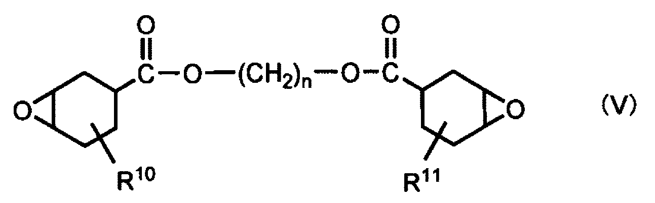
[式(V)中、R10及びR11は、互いに独立して、水素原子又は炭素数1~5の直鎖状アルキル基を表し、nは2~20の整数を表す。]
[b] Epoxycyclohexane carboxylates of alkanediols represented by the following formula (V):
[In formula (V), R 10 and R 11 each independently represent a hydrogen atom or a linear alkyl group having 1 to 5 carbon atoms, and n represents an integer of 2 to 20.]
[c]下記式(VI)で示されるジカルボン酸のエポキシシクロヘキシルメチルエステル類:

[式(VI)中、R12及びR13は、互いに独立して、水素原子又は炭素数1~5の直鎖状アルキル基を表し、pは2~20の整数を表す。]
[c] Epoxycyclohexylmethyl esters of dicarboxylic acids represented by the following formula (VI):
[In formula (VI), R 12 and R 13 each independently represent a hydrogen atom or a linear alkyl group having 1 to 5 carbon atoms, and p represents an integer of 2 to 20.]
[d]下記式(VII)で示されるポリエチレングリコールのエポキシシクロヘキシルメチルエーテル類:

[式(VII)中、R14及びR15は、互いに独立して、水素原子又は炭素数1~5の直鎖状アルキル基を表し、qは2~10の整数を表す。]
[d] Epoxycyclohexylmethyl ethers of polyethylene glycol represented by the following formula (VII):
[In formula (VII), R 14 and R 15 each independently represent a hydrogen atom or a linear alkyl group having 1 to 5 carbon atoms, and q represents an integer of 2 to 10.]
[e]下記式(VIII)で示されるアルカンジオールのエポキシシクロヘキシルメチルエーテル類:

[式(VIII)中、R16及びR17は、互いに独立して、水素原子又は炭素数1~5の直鎖状アルキル基を表し、rは2~20の整数を表す。]
[e] Epoxycyclohexylmethyl ethers of alkanediols represented by the following formula (VIII):
[In formula (VIII), R 16 and R 17 each independently represent a hydrogen atom or a linear alkyl group having 1 to 5 carbon atoms, and r represents an integer of 2 to 20.]
[f]下記式(IX)で示されるジエポキシトリスピロ化合物:
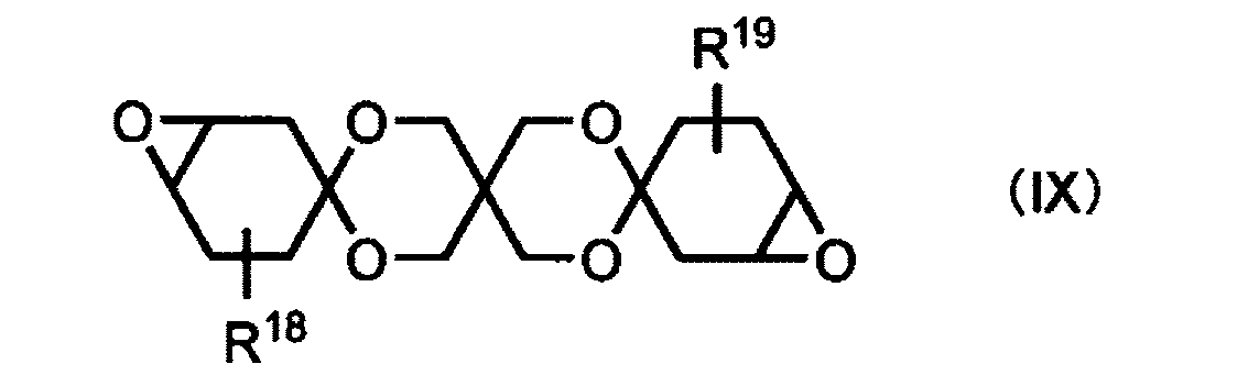
[式(IX)中、R18及びR19は、互いに独立して、水素原子又は炭素数1~5の直鎖状アルキル基を表す。]
[f] A diepoxy trispiro compound represented by the following formula (IX):
[In formula (IX), R 18 and R 19 each independently represent a hydrogen atom or a linear alkyl group having 1 to 5 carbon atoms.]
[g]下記式(X)で示されるジエポキシモノスピロ化合物:

[式(X)中、R20及びR21は、互いに独立して、水素原子又は炭素数1~5の直鎖状アルキル基を表す。]
[g] A diepoxy monospiro compound represented by the following formula (X):
[In formula (X), R 20 and R 21 each independently represent a hydrogen atom or a linear alkyl group having 1 to 5 carbon atoms.]
[h]下記式(XI)で示されるビニルシクロヘキセンジエポキシド類:
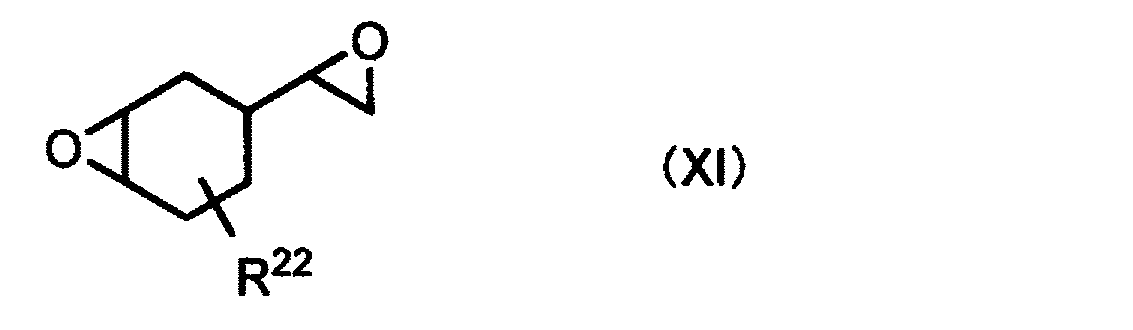
[式(XI)中、R22は、水素原子又は炭素数1~5の直鎖状アルキル基を表す。]
[h] Vinylcyclohexene diepoxides represented by the following formula (XI):
[In formula (XI), R 22 represents a hydrogen atom or a linear alkyl group having 1 to 5 carbon atoms.]
[i]下記式(XII)で示されるエポキシシクロペンチルエーテル類:

[式(XII)中、R23及びR24は、互いに独立して、水素原子又は炭素数1~5の直鎖状アルキル基を表す。]
[i] Epoxy cyclopentyl ethers represented by the following formula (XII):
[In formula (XII), R 23 and R 24 each independently represent a hydrogen atom or a linear alkyl group having 1 to 5 carbon atoms.]
[j]下記式(XIII)で示されるジエポキシトリシクロデカン類:
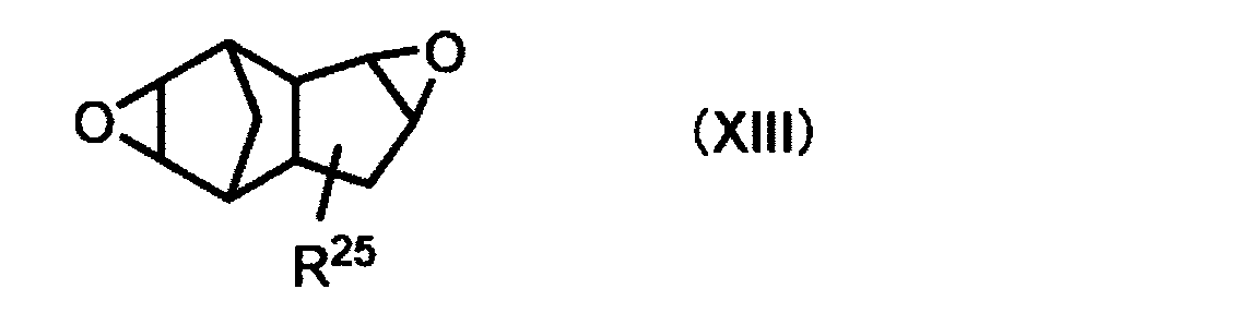
[式(XIII)中、R25は、水素原子又は炭素数1~5の直鎖状アルキル基を表す。]
[j] Diepoxytricyclodecanes represented by the following formula (XIII):
[In formula (XIII), R 25 represents a hydrogen atom or a linear alkyl group having 1 to 5 carbon atoms.]
脂肪族エポキシ化合物としては、脂肪族多価アルコール又はそのアルキレンオキサイド付加物のポリグリシジルエーテルが挙げられる。より具体的には、1,4-ブタンジオールのジグリシジルエーテル;1,6-ヘキサンジオールのジグリシジルエーテル;グリセリンのトリグリシジルエーテル;トリメチロールプロパンのトリグリシジルエーテル;ポリエチレングリコールのジグリシジルエーテル;プロピレングリコールのジグリシジルエーテル;エチレングリコール、プロピレングリコール又はグリセリン等の脂肪族多価アルコールに1種又は2種以上のアルキレンオキサイド(エチレンオキサイドやプロピレンオキサイド)を付加することにより得られるポリエーテルポリオールのポリグリシジルエーテル等が挙げられる。 Examples of aliphatic epoxy compounds include polyglycidyl ethers of aliphatic polyhydric alcohols or their alkylene oxide adducts. More specifically, they include diglycidyl ether of 1,4-butanediol; diglycidyl ether of 1,6-hexanediol; triglycidyl ether of glycerin; triglycidyl ether of trimethylolpropane; diglycidyl ether of polyethylene glycol; diglycidyl ether of propylene glycol; and polyglycidyl ethers of polyether polyols obtained by adding one or more alkylene oxides (ethylene oxide or propylene oxide) to aliphatic polyhydric alcohols such as ethylene glycol, propylene glycol, or glycerin.
水素化エポキシ化合物は、芳香族ポリオールの芳香環に水素化反応を行って得られる脂環式ポリオールに、エピクロロヒドリンを反応させることにより得られるものである。芳香族ポリオールとしては、ビスフェノールA、ビスフェノールF、ビスフェノールS等のビスフェノール型化合物;フェノールノボラック樹脂、クレゾールノボラック樹脂、ヒドロキシベンズアルデヒドフェノールノボラック樹脂等のノボラック型樹脂;テトラヒドロキシジフェニルメタン、テトラヒドロキシベンゾフェノン、ポリビニルフェノール等の多官能型の化合物が挙げられる。水素化エポキシ化合物の中でも好ましいものとして、水素化されたビスフェノールAのジグリシジルエーテルが挙げられる。 Hydrogenated epoxy compounds are obtained by reacting epichlorohydrin with an alicyclic polyol obtained by hydrogenating the aromatic rings of an aromatic polyol. Examples of aromatic polyols include bisphenol-type compounds such as bisphenol A, bisphenol F, and bisphenol S; novolac-type resins such as phenol novolac resin, cresol novolac resin, and hydroxybenzaldehyde phenol novolac resin; and polyfunctional compounds such as tetrahydroxydiphenylmethane, tetrahydroxybenzophenone, and polyvinylphenol. Among the hydrogenated epoxy compounds, hydrogenated diglycidyl ether of bisphenol A is preferred.
硬化性樹脂(X)は、エポキシ化合物等の活性エネルギー線硬化性化合物とともに(メタ)アクリル系化合物等を含有してもよい。(メタ)アクリル系化合物を併用することにより、偏光子10の偏光領域11及び第1補強材50のセル領域55と、非偏光領域12及び非セル領域56を形成する硬化性樹脂(X)の硬化物との間の密着性、硬化性樹脂(X)の硬化物の硬度及び機械的強度を高める効果が期待でき、さらには、硬化性樹脂(X)の粘度や硬化速度等の調整をより容易に行うことができるようになる。「(メタ)アクリル」は、アクリル及びメタクリルからなる群より選択される少なくとも一方を意味する。
The curable resin (X) may contain a (meth)acrylic compound or the like together with an active energy ray curable compound such as an epoxy compound. By using a (meth)acrylic compound in combination, it is expected that the adhesion between the
硬化性樹脂(X)を含む硬化性樹脂組成物は、重合開始剤を含むことが好ましい。重合開始剤としては、光カチオン系重合剤等のカチオン系重合剤やラジカル重合開始剤が挙げられる。光カチオン系重合開始剤は、可視光線、紫外線、X線、電子線等の活性エネルギー線の照射によりカチオン種又はルイス酸を発生し、エポキシ基の重合反応を開始させるものである。上述のように硬化性樹脂(X)は、紫外線の照射によって硬化する紫外線硬化性樹脂であることが好ましく、硬化性樹脂(X)は脂環式エポキシ化合物を含むことが好ましいため、この場合の重合開始剤は、紫外線の照射によりカチオン種又はルイス酸を発生するものが好ましい。 The curable resin composition containing the curable resin (X) preferably contains a polymerization initiator. Examples of the polymerization initiator include cationic polymerization agents such as photocationic polymerization agents and radical polymerization initiators. The photocationic polymerization initiator generates cationic species or Lewis acids by irradiation with active energy rays such as visible light, ultraviolet light, X-rays, and electron beams, and initiates the polymerization reaction of the epoxy group. As described above, the curable resin (X) is preferably an ultraviolet-curable resin that cures by irradiation with ultraviolet light, and since the curable resin (X) preferably contains an alicyclic epoxy compound, the polymerization initiator in this case is preferably one that generates cationic species or Lewis acids by irradiation with ultraviolet light.
硬化性樹脂組成物は、さらに、光増感剤、重合促進剤、イオントラップ剤、酸化防止剤、連鎖移動剤、粘着付与剤、熱可塑性樹脂、充填剤、流動調整剤、可塑剤、消泡剤、帯電防止剤、レベリング剤等の添加剤を含有することができる。 The curable resin composition may further contain additives such as photosensitizers, polymerization accelerators, ion trapping agents, antioxidants, chain transfer agents, tackifiers, thermoplastic resins, fillers, flow control agents, plasticizers, defoamers, antistatic agents, and leveling agents.
(充填材)
第1補強材50及び第2補強材60に設けてもよい充填材は透光性を有し、第1補強材50の第1セル51の内部空間及び第2補強材60の第2セル61の内部空間を埋めることができるものであれば特に限定されない。充填材は、第1補強材50のセル隔壁53及び第2補強材60のセル隔壁63を構成する材料とは異なる材料であることが好ましく、樹脂材料を含むことが好ましい。当該樹脂材料としては、例えば、熱可塑性樹脂、熱硬化性樹脂や活性エネルギー線硬化性樹脂等の硬化性樹脂等からなる群より選ばれる1種以上が挙げられ、粘着剤又は接着剤であってもよい。
(Filling material)
The filler that may be provided in the first reinforcing
熱可塑性樹脂としては、鎖状ポリオレフィン系樹脂(ポリプロピレン系樹脂等)、環状ポリオレフィン系樹脂(ノルボルネン系樹脂等)等のポリオレフィン系樹脂;トリアセチルセルロース、ジアセチルセルロース等のセルロースエステル系樹脂;ポリエチレンテレフタレート、ポリエチレンナフタレート、ポリブチレンテレフタレート等のポリエステル系樹脂;ポリカーボネート系樹脂;(メタ)アクリル系樹脂;ポリスチレン系樹脂;ポリエーテル系樹脂;ポリウレタン系樹脂;ポリアミド系樹脂;ポリイミド系樹脂;フッ素系樹脂等が挙げられる。 Examples of thermoplastic resins include polyolefin resins such as linear polyolefin resins (polypropylene resins, etc.) and cyclic polyolefin resins (norbornene resins, etc.); cellulose ester resins such as triacetyl cellulose and diacetyl cellulose; polyester resins such as polyethylene terephthalate, polyethylene naphthalate, and polybutylene terephthalate; polycarbonate resins; (meth)acrylic resins; polystyrene resins; polyether resins; polyurethane resins; polyamide resins; polyimide resins; and fluorine resins.
硬化性樹脂としては、例えば上記した硬化性樹脂(X)が挙げられる。 The curable resin may be, for example, the curable resin (X) described above.
粘着剤は、それ自体を被着体に貼り付けることで接着性を発現するものであり、いわゆる感圧型接着剤と称されるものである。粘着剤としては、(メタ)アクリル系ポリマー、シリコーン系ポリマー、ポリエステル系ポリマー、ポリウレタン系ポリマー、ポリエーテル系ポリマー、又はゴム系ポリマー等のポリマーを主成分として含むものが挙げられる。本明細書において、主成分とは、粘着剤の全固形分のうち50質量%以上を含む成分をいう。粘着剤は、活性エネルギー線硬化型、熱硬化型であってもよく、活性エネルギー線照射や加熱により、架橋度や接着力を調整してもよい。 An adhesive exhibits adhesive properties by attaching itself to an adherend, and is known as a pressure-sensitive adhesive. Examples of adhesives include those that contain a polymer, such as a (meth)acrylic polymer, a silicone polymer, a polyester polymer, a polyurethane polymer, a polyether polymer, or a rubber polymer, as the main component. In this specification, the main component refers to a component that contains 50% by mass or more of the total solid content of the adhesive. The adhesive may be of the active energy ray curing type or the heat curing type, and the degree of crosslinking or adhesive strength may be adjusted by irradiation with active energy rays or heating.
接着剤は、硬化性の樹脂成分を含むものであって、感圧型接着剤(粘着剤)以外の接着剤である。接着剤としては、硬化性の樹脂成分を水に溶解又は分散させた水系接着剤、活性エネルギー線硬化性化合物を含有する活性エネルギー線硬化性接着剤、熱硬化性接着剤等が挙げられる。 The adhesive contains a curable resin component and is an adhesive other than a pressure-sensitive adhesive (adhesive). Examples of adhesives include water-based adhesives in which a curable resin component is dissolved or dispersed in water, active energy ray-curable adhesives containing active energy ray-curable compounds, and thermosetting adhesives.
接着剤として、偏光板の技術分野で汎用されている水系接着剤を用いることもできる。水系接着剤に含有される樹脂成分としては、ポリビニルアルコール系樹脂やウレタン系樹脂等が挙げられる。活性エネルギー線硬化性接着剤としては、紫外線、可視光、電子線、X線等の活性エネルギー線の照射によって硬化する組成物が挙げられる。活性エネルギー線硬化性接着剤としては、上記した硬化性樹脂(X)を含む硬化性樹脂組成物を用いてもよい。熱硬化性接着剤としては、エポキシ系樹脂、シリコーン系樹脂、フェノール系樹脂、メラミン系樹脂等を主成分として含むものが挙げられる。 As the adhesive, a water-based adhesive that is widely used in the technical field of polarizing plates can be used. Examples of resin components contained in the water-based adhesive include polyvinyl alcohol-based resins and urethane-based resins. Examples of active energy ray-curable adhesives include compositions that are cured by irradiation with active energy rays such as ultraviolet light, visible light, electron beams, and X-rays. Examples of active energy ray-curable adhesives include curable resin compositions containing the above-mentioned curable resin (X). Examples of thermosetting adhesives include those containing epoxy-based resins, silicone-based resins, phenol-based resins, melamine-based resins, etc. as the main component.
(偏光子複合体の製造方法)
図4及び図5は、偏光子複合体40(図1(a))の製造方法の一例を模式的に示す概略断面図である。図4及び図5では、図1(a)に示す偏光子複合体40を得る場合を示しているが、図2(a)及び(b)に示す偏光子複合体40も、下記に説明する方法によって製造することができる。偏光子複合体40は、例えば、全体が同じ視感度補正偏光度(Py)を有し、非偏光領域12を有していない原料偏光子20の片面側に、セル領域55のみからなり非セル領域56を有していない補強材形成用構造体58(以下、「構造体58」ということがある。)を形成したものを用いて製造することができる。原料偏光子20は上記した偏光子10の偏光領域11のみで形成されているため、原料偏光子20の厚みは、偏光子10の偏光領域11と同じ厚みである15μm以下であることが好ましい。構造体58は上記した第1補強材50のセル領域55となるため、第1補強材50のセル領域55と同じ厚みを有することが好ましい。
(Method of Manufacturing Polarizer Composite)
4 and 5 are schematic cross-sectional views showing an example of a method for producing a polarizer composite 40 (FIG. 1(a)). Although FIG. 4 and FIG. 5 show a case where the
偏光子複合体40は、例えば次の工程で製造することができる。まず、図4(a)に示すように、原料偏光子20の一方の面に、原料偏光子20に対して剥離可能に第1支持層25を設けた後、原料偏光子20の他方の面に構造体58を形成して、第1積層体31を準備する。構造体58は、例えば、樹脂材料又は無機酸化物を用いて、原料偏光子20の表面に第1セル51を区画するセル隔壁53を形成することによって得ることができる。
The
樹脂材料を用いてセル隔壁53を形成する方法としては特に限定されないが、例えば、インクジェット印刷、スクリーン印刷、グラビア印刷等の印刷法;フォトリソグラフィ法;ノズルやダイ等を用いた塗布法等が挙げられる。上記方法では、樹脂材料を、溶媒、添加剤等と混合した樹脂組成物を用いてもよい。添加剤としては、レベリング剤、酸化防止剤、可塑剤、粘着付与剤、有機又は無機の充填剤、顔料、老化防止剤、紫外線吸収剤、酸化防止剤等が挙げられる。セル隔壁53は、印刷又は塗布された樹脂組成物に、必要に応じて固化又は硬化のための処理を行って形成してもよい。
The method for forming the
無機酸化物を用いてセル隔壁53を形成する方法としては特に限定されないが、例えば、無機酸化物を蒸着することによって形成することができる。
There are no particular limitations on the method for forming the
準備した第1積層体31に対して、打抜き、切抜き、切削、又はレーザーカット等により積層方向に貫通する貫通穴32を形成する(図4(b))。これにより、貫通穴が形成された第1支持層25上に、原料偏光子20に貫通穴22が形成された穴あき偏光子21、及び、構造体58に貫通穴52が形成された穴あき構造体59が形成される。続いて、貫通穴32が形成された第1積層体31の穴あき構造体59側に第2支持層26を剥離可能に設けた後(図4(c))、第1支持層25を剥離する(図4(d))。これにより、第2支持層26、穴あき構造体59、及び穴あき偏光子21がこの順に積層された第2積層体33を得る(図4(d))。第2支持層26は、穴あき構造体59の貫通穴52の一方側を塞ぐように設ける。
The prepared
次に、第2積層体33の穴あき偏光子21の貫通穴22及び穴あき構造体59の貫通穴52に硬化性樹脂(X)を含む硬化性樹脂組成物を充填し、活性エネルギー線を照射することにより、貫通穴22,52内の硬化性樹脂(X)を硬化させる。これにより、穴あき偏光子21の貫通穴22及び穴あき構造体59の貫通穴52に硬化性樹脂(X)の硬化物を形成し、第2支持層26上に、第1補強材50及び偏光子10を形成する(図5(a))。図5(a)に示す偏光子10は、穴あき偏光子21の貫通穴22以外の領域が偏光領域11となり、硬化物が設けられた貫通穴22の領域が非偏光領域12となったものである。図5(a)に示す第1補強材50は、偏光子10の一方の面側に設けられ、穴あき構造体59の貫通穴52以外の領域がセル領域55となり、硬化物が設けられた貫通穴52の領域が非セル領域56となったものである。
Next, the through
続いて、偏光子10の第1補強材50側とは反対側に、第2補強材60を形成して、第2支持層26上に偏光子複合体40を形成する(図5(b))。第2補強材60は、例えば、上記した構造体58のセル隔壁53を形成する方法で説明した方法によって、セル隔壁63を形成すればよい。第2補強材60を形成した後に、第2支持層26は剥離してもよい。
Next, a second reinforcing
穴あき偏光子21の貫通穴22及び穴あき構造体59の貫通穴52に硬化性樹脂組成物を充填する方法としては、特に限定されない。例えば、分注器又はディスペンサー等を用いて第2積層体33の貫通穴22,52に硬化性樹脂組成物を注入してもよく、第2積層体33の穴あき偏光子21の表面上に硬化性樹脂組成物をコーティングしながら、貫通穴22,52に硬化性樹脂組成物を充填してもよい。穴あき偏光子21の表面上にコーティングされた硬化性樹脂組成物の硬化物層は、後述する保護層とすることができる。硬化性樹脂組成物をコーティングする場合は、コーティングにより形成された塗布層表面を覆うように基材フィルムを設けてもよい。基材フィルムは、硬化性樹脂(X)の硬化後に剥離してもよい。
The method of filling the through
第1支持層25は、後述する原料偏光子20の製造時に用いられる支持層であってもよく、硬化性樹脂組成物をコーティングする際に用いた上記基材フィルムを用いてもよい。あるいは、原料偏光子20に、水等の揮発性液体によって貼合された剥離可能な支持層であってもよく、原料偏光子20に対して剥離可能な粘着シートであってもよい。第2支持層26は、穴あき偏光子21に水貼等の揮発性液体によって貼合された剥離可能な支持層であってもよく、穴あき偏光子21に対して剥離可能な粘着シートであってもよい。
The
上記のように、偏光子複合体40では、原料偏光子20の厚みが15μm以下であることにより、穴あき偏光子21に設けられる貫通穴22の深さも15μm以下とすることができる。穴あき構造体59の第1セル51の高さも通常15μm以下であるため、穴あき構造体59に設けられる貫通穴52の深さも15μm以下とすることができる。これにより、穴あき偏光子21の貫通穴22及び穴あき構造体59の貫通穴52への硬化性樹脂組成物の充填や、貫通穴22,52に充填された硬化性樹脂組成物に含まれる硬化性樹脂(X)の硬化処理を短時間で行うことができるため、作業性の低下を抑制できる。
As described above, in the
偏光子複合体40の製造方法では、構造体58、原料偏光子20、及び第1支持層25をこの順に有する第1積層体31に、貫通穴32を形成している。原料偏光子20は、偏光子10の非偏光領域12となる領域を形成するものであり、その厚みは15μm以下と薄いため、原料偏光子20に貫通穴22を形成する際に貫通穴22の周辺にクラックが発生する等の不具合を生じる虞がある。偏光子複合体40の製造方法では、原料偏光子20に構造体58を設け、原料偏光子20を構造体58によって補強した状態で貫通穴22を形成するため、穴あき偏光子21にクラックが発生することを抑制し、クラックの発生が抑制された偏光子10を得ることができる。
In the manufacturing method of the
(原料偏光子)
原料偏光子20は、貫通穴22に充填された硬化性樹脂組成物中の硬化性樹脂(X)を硬化させるために照射する活性エネルギー線によって著しく変質しにくいものであることが好ましい。このような原料偏光子20は、例えば、ポリビニルアルコール系樹脂フィルムに二色性色素を吸着配向させたフィルムや、重合性液晶化合物の硬化層中で二色性色素が配向しているものであり、これらの製造方法は、上述の偏光領域11において説明したとおりである。
(Raw material polarizer)
It is preferable that
(補強材形成用構造体(構造体))
構造体58は、セル領域55のみからなり非セル領域56を有していない構造体である。構造体58は、上記したように、樹脂材料又は無機酸化物を用いて、第1セル51を区画するセル隔壁53を形成することによって得ることができる。樹脂材料及び無機酸化物として用いることができる材料、及びこれらを用いてセル隔壁53を形成する方法としては、上記で例示した材料及び方法が挙げられる。
(Structure for forming reinforcement material (structure))
The
<光学積層体>
図6は、本実施形態の光学積層体の一例を模式的に示す概略断面図である。図6に示す光学積層体45は、図1(a)に示す偏光子複合体40の両面側に保護層17,18を有する。光学積層体45は、偏光子複合体40の片面側にのみ保護層17(又は18)を有するものであってもよい。光学積層体45に含まれる偏光子複合体40は、図2(a)又は(b)に示す偏光子複合体40であってもよい。保護層17,18は、粘着剤層又は接着剤層等の貼合層を介して偏光子複合体40上に設けることができる。この場合、例えば、貼合層を介して、偏光子複合体40にフィルム状の保護層を積層すればよい。保護層17,18は、貼合層を介さずに偏光子複合体40に直接接するように設けてもよい。この場合、例えば、保護層17,18を構成する樹脂材料を含む組成物を、偏光子複合体40上に塗布し、この塗布層を固化又は硬化すること等によって保護層17,18を形成することができる。
<Optical laminate>
FIG. 6 is a schematic cross-sectional view showing an example of the optical laminate of the present embodiment. The
光学積層体45が、偏光子複合体40の第1補強材50及び第2補強材60上にそれぞれ、貼合層を介して保護層18,17を設けたものである場合、第1補強材50の第1セル51の内部空間、複数の第1セル51の間の隙間、第2補強材60の第2セル61の内部空間、及び複数の第2セル61の間の隙間等を埋めるように貼合層を設けて、保護層18,17を形成することが好ましい。
When the
光学積層体45が、偏光子複合体40の第1補強材50及び第2補強材60上にそれぞれ直接接するように保護層18,17を設けたものである場合は、第1補強材50の第1セル51の内部空間、複数の第1セル51の間の隙間、第2補強材60の第2セル61の内部空間、及び複数の第2セル61の間の隙間等を埋めるように、保護層18,17を構成する樹脂材料を含む組成物を設けて、保護層18,17を形成することが好ましい。
When the
光学積層体45において保護層18,17は、第1補強材50及び第2補強材60上にそれぞれ直接設けられた硬化性樹脂(X)の硬化物層であってもよい。硬化物層である保護層18,17を構成する硬化性樹脂(X)としては、紫外線、可視光、電子線、X線等の活性エネルギー線の照射によって硬化する樹脂であれば特に限定されず、例えば上記で説明した硬化性樹脂(X)が挙げられる。保護層18,17は、偏光子10の非偏光領域12及び非セル領域56に含まれる硬化物を構成する硬化性樹脂(X)と同じ硬化性樹脂(X)を含む硬化性樹脂組成物の硬化物層であってもよい。
In the
光学積層体45を製造するためには、例えば、偏光子複合体40の第1補強材50及び第2補強材60側に硬化性樹脂組成物をコーティングし、活性エネルギー線を照射することによって硬化性樹脂(X)を硬化させる。これにより、第1補強材50及び第2補強材60上にそれぞれ、硬化性樹脂(X)の硬化物層である保護層18,17を形成して光学積層体45を得てもよい。
To manufacture the
図6に示す光学積層体45において、保護層17,18は、一方を貼合層を介して設けた保護層とし、他方を貼合層を介さずに設けた保護層としてもよい。光学積層体45に含まれる保護層17,18は、互いに同じであってもよく、互いに異なっていてもよい。
In the
硬化性樹脂組成物をコーティングする場合は、コーティングにより形成された塗布層表面を覆うように基材フィルムを設けてもよい。この場合、基材フィルムを保護層17,18とし、硬化性樹脂(X)の硬化物層を保護層17,18を貼合するための貼合層としてもよい。基材フィルムは、硬化性樹脂(X)の硬化後に剥離してもよい。
When the curable resin composition is coated, a substrate film may be provided so as to cover the surface of the coating layer formed by the coating. In this case, the substrate film may be used as the
(保護層)
保護層17,18は、光を透過可能な樹脂層であることが好ましく、樹脂フィルムであってもよく、樹脂材料を含む組成物を塗布して形成した塗布層であってもよい。樹脂層に用いられる樹脂としては、透明性、機械的強度、熱安定性、水分遮断性、等方性、延伸性等に優れる熱可塑性樹脂であることが好ましい。熱可塑性樹脂としては、上記した原料偏光子20の製造に用いてもよい基材フィルムを構成する熱可塑性樹脂が挙げられる。光学積層体45が両面に保護層17,18を有する場合、保護層17,18の樹脂組成は、互いに同一であってもよく、互いに異なっていてもよい。
(Protective Layer)
The protective layers 17 and 18 are preferably resin layers capable of transmitting light, and may be resin films or coating layers formed by applying a composition containing a resin material. The resin used for the resin layer is preferably a thermoplastic resin having excellent transparency, mechanical strength, thermal stability, moisture blocking properties, isotropy, stretchability, etc. Examples of the thermoplastic resin include the thermoplastic resin constituting the base film that may be used in the manufacture of the
保護層17,18の厚みは、薄型化の観点から、通常200μm以下であり、150μm以下であることが好ましく、100μm以下であることがより好ましく、80μm以下であってもよく、60μm以下であってもよい。保護層17,18の厚みは、通常5μm以上であり、10μm以上であってもよく、20μm以上であってもよい。保護層17,18は位相差を有していても、有していなくてもよい。光学積層体45が両面に保護層17,18を有する場合、保護層17,18の厚みは、互いに同一であってもよく、互いに異なっていてもよい。
From the viewpoint of thinning, the thickness of the
(貼合層)
貼合層は、粘着剤層又は接着剤層である。粘着剤層を形成するための粘着剤及び接着剤層を形成するための接着剤としては、例えば、上記した充填材を構成するために用いる粘着剤及び接着剤が挙げられる。
(Laminating layer)
The attachment layer is a pressure-sensitive adhesive layer or an adhesive layer. Examples of the pressure-sensitive adhesive for forming the pressure-sensitive adhesive layer and the adhesive for forming the adhesive layer include the pressure-sensitive adhesive and adhesive used to form the filler described above.
<光学表示素子用貼合層を有する積層体>
図1及び図2に示す偏光子複合体40、図6に示す光学積層体45は、さらに、液晶表示装置や有機EL表示装置等の表示装置の光学表示素子(液晶パネル、有機EL素子)に貼合するための光学表示素子用貼合層を有していてもよい。
<Laminate having an adhesive layer for optical display element>
The
偏光子複合体40及び光学積層体45において、第1補強材50又は第2補強材60の表面に光学表示素子用貼合層を設ける場合は、第1補強材50又は第2補強材60に設けられる充填材として光学表示素子用貼合層を構成する材料を用い、第1補強材50の第1セル51の内部空間又は第2補強材60の第2セル61の内部空間等への充填材の充填と、光学表示素子用貼合層の形成とを、同時に行ってもよい。
In the
10 偏光子、11 偏光領域、11m 第1平面、11n 第2平面、12 非偏光領域、17,18 保護層、20 原料偏光子、21 穴あき偏光子、22 貫通穴、25 第1支持層、26 第2支持層、27 第3支持層、28 第4支持層、31 第1積層体、32 貫通穴、33 第2積層体、34 第3積層体、35 第4積層体、36
貫通穴、40,41 偏光子複合体、45 光学積層体、50 第1補強材、51 第1セル、52 貫通穴、53 セル隔壁、55 セル領域、56 非セル領域、58 補強材形成用構造体、59 穴あき構造体、60 第2補強材、61 第2セル、63 セル隔壁。
REFERENCE SIGNS
Through hole, 40, 41 polarizer composite, 45 optical laminate, 50 first reinforcing material, 51 first cell, 52 through hole, 53 cell partition wall, 55 cell region, 56 non-cell region, 58 reinforcing material forming structure, 59 holed structure, 60 second reinforcing material, 61 second cell, 63 cell partition wall.
Claims (12)
前記偏光子は、厚みが15μm以下の偏光領域と、平面視において前記偏光領域に囲まれた非偏光領域と、を有し、
前記第1補強材は、
開口端面を有する第1セルを複数有し、且つ、各開口端面が前記偏光子の面に対向するように配列しており、
前記第1セルが存在し且つ前記偏光領域に対応する領域に存在するセル領域と、前記第1セルが存在せず且つ前記非偏光領域に対応する領域に存在する非セル領域と、を有し、
前記第2補強材は、
開口端面を有する第2セルを複数有し、且つ、各開口端面が前記偏光子の面に対向するように配列しており、
少なくとも前記非偏光領域に対応する領域に前記第2セルが存在し、
前記非偏光領域及び前記非セル領域は、活性エネルギー線硬化性樹脂の硬化物を含み、
前記非偏光領域に含まれる前記硬化物は、平面視において前記偏光領域に囲まれた貫通穴に設けられている、偏光子複合体。 A polarizer composite including a polarizer, a first reinforcing material provided on one surface side of the polarizer, and a second reinforcing material provided on the other surface side of the polarizer,
the polarizer has a polarizing region having a thickness of 15 μm or less and a non-polarizing region surrounded by the polarizing region in a plan view,
The first reinforcing material is
a plurality of first cells each having an open end face, the first cells being arranged so that each open end face faces a surface of the polarizer;
a cell region in which the first cell is present and which is located in a region corresponding to the polarizing region, and a non-cell region in which the first cell is not present and which is located in a region corresponding to the non-polarizing region,
The second reinforcing material is
a plurality of second cells each having an open end face, the second cells being arranged so that each open end face faces a surface of the polarizer;
the second cell is present at least in an area corresponding to the non-polarizing area,
the non-polarizing region and the non-cell region contain a cured product of an active energy ray-curable resin,
A polarizer composite, wherein the cured material contained in the non-polarizing region is provided in a through hole surrounded by the polarizing region in a plan view.
Priority Applications (5)
| Application Number | Priority Date | Filing Date | Title |
|---|---|---|---|
| JP2019194277A JP7516028B2 (en) | 2019-10-25 | 2019-10-25 | Polarizer composite and optical laminate |
| PCT/JP2020/032327 WO2021079614A1 (en) | 2019-10-25 | 2020-08-27 | Polarizer complex and optical laminate |
| CN202080073998.1A CN114631044A (en) | 2019-10-25 | 2020-08-27 | Polarizing plate composite and optical laminate |
| KR1020227017172A KR102780318B1 (en) | 2019-10-25 | 2020-08-27 | Polarizer complex and optical laminate |
| TW109130591A TWI864093B (en) | 2019-10-25 | 2020-09-07 | Polarizer composite and optical laminate |
Applications Claiming Priority (1)
| Application Number | Priority Date | Filing Date | Title |
|---|---|---|---|
| JP2019194277A JP7516028B2 (en) | 2019-10-25 | 2019-10-25 | Polarizer composite and optical laminate |
Publications (2)
| Publication Number | Publication Date |
|---|---|
| JP2021067868A JP2021067868A (en) | 2021-04-30 |
| JP7516028B2 true JP7516028B2 (en) | 2024-07-16 |
Family
ID=75620467
Family Applications (1)
| Application Number | Title | Priority Date | Filing Date |
|---|---|---|---|
| JP2019194277A Active JP7516028B2 (en) | 2019-10-25 | 2019-10-25 | Polarizer composite and optical laminate |
Country Status (5)
| Country | Link |
|---|---|
| JP (1) | JP7516028B2 (en) |
| KR (1) | KR102780318B1 (en) |
| CN (1) | CN114631044A (en) |
| TW (1) | TWI864093B (en) |
| WO (1) | WO2021079614A1 (en) |
Families Citing this family (1)
| Publication number | Priority date | Publication date | Assignee | Title |
|---|---|---|---|---|
| CN110867136B (en) * | 2019-11-22 | 2021-10-15 | 维沃移动通信有限公司 | Pole screen and electronic equipment |
Citations (5)
| Publication number | Priority date | Publication date | Assignee | Title |
|---|---|---|---|---|
| US20140118826A1 (en) | 2012-10-30 | 2014-05-01 | Apple Inc. | Displays With Polarizer Layers for Electronic Devices |
| US20170176657A1 (en) | 2013-11-08 | 2017-06-22 | Apple Inc. | Electronic Device Display With Polarizer Windows |
| JP2018128664A (en) | 2017-02-10 | 2018-08-16 | 日東電工株式会社 | Polarizing film, image display device, and manufacturing method of the polarizing film |
| JP2018128666A (en) | 2017-02-10 | 2018-08-16 | 日東電工株式会社 | Polarizing film, image display device, and manufacturing method of the polarizing film |
| CN110208891A (en) | 2019-05-21 | 2019-09-06 | 华为技术有限公司 | A kind of polaroid, display screen and mobile terminal |
Family Cites Families (6)
| Publication number | Priority date | Publication date | Assignee | Title |
|---|---|---|---|---|
| US8467177B2 (en) * | 2010-10-29 | 2013-06-18 | Apple Inc. | Displays with polarizer windows and opaque masking layers for electronic devices |
| JP6214594B2 (en) | 2014-04-25 | 2017-10-18 | 日東電工株式会社 | Polarizer, polarizing plate and image display device |
| JP6152127B2 (en) * | 2015-02-16 | 2017-06-21 | 日東電工株式会社 | Polarizer, polarizing plate and image display device |
| JP2018025635A (en) * | 2016-08-09 | 2018-02-15 | 株式会社東海理化電機製作所 | Polarizing plate and laser processing method for polarizing plate |
| JP6952779B2 (en) * | 2017-07-21 | 2021-10-20 | 富士フイルム株式会社 | Liquid crystal display |
| JP7404029B2 (en) * | 2019-10-25 | 2023-12-25 | 住友化学株式会社 | optical laminate |
-
2019
- 2019-10-25 JP JP2019194277A patent/JP7516028B2/en active Active
-
2020
- 2020-08-27 CN CN202080073998.1A patent/CN114631044A/en active Pending
- 2020-08-27 KR KR1020227017172A patent/KR102780318B1/en active Active
- 2020-08-27 WO PCT/JP2020/032327 patent/WO2021079614A1/en not_active Ceased
- 2020-09-07 TW TW109130591A patent/TWI864093B/en active
Patent Citations (5)
| Publication number | Priority date | Publication date | Assignee | Title |
|---|---|---|---|---|
| US20140118826A1 (en) | 2012-10-30 | 2014-05-01 | Apple Inc. | Displays With Polarizer Layers for Electronic Devices |
| US20170176657A1 (en) | 2013-11-08 | 2017-06-22 | Apple Inc. | Electronic Device Display With Polarizer Windows |
| JP2018128664A (en) | 2017-02-10 | 2018-08-16 | 日東電工株式会社 | Polarizing film, image display device, and manufacturing method of the polarizing film |
| JP2018128666A (en) | 2017-02-10 | 2018-08-16 | 日東電工株式会社 | Polarizing film, image display device, and manufacturing method of the polarizing film |
| CN110208891A (en) | 2019-05-21 | 2019-09-06 | 华为技术有限公司 | A kind of polaroid, display screen and mobile terminal |
Also Published As
| Publication number | Publication date |
|---|---|
| TW202117369A (en) | 2021-05-01 |
| KR20220084397A (en) | 2022-06-21 |
| KR102780318B1 (en) | 2025-03-11 |
| JP2021067868A (en) | 2021-04-30 |
| WO2021079614A1 (en) | 2021-04-29 |
| TWI864093B (en) | 2024-12-01 |
| CN114631044A (en) | 2022-06-14 |
Similar Documents
| Publication | Publication Date | Title |
|---|---|---|
| TWI880948B (en) | Optical laminate | |
| JP7456748B2 (en) | optical laminate | |
| JP7516028B2 (en) | Polarizer composite and optical laminate | |
| JP7516027B2 (en) | Optical laminate | |
| JP2024036510A (en) | optical laminate | |
| TWI857133B (en) | Polarizer composite and optical laminate | |
| KR102925419B1 (en) | Polarizer complexes and optical laminates | |
| KR101748531B1 (en) | Polarizing plate set and liquid crystal panel | |
| TW201609414A (en) | Polarizing plate, high brightness polarizing and IPS mode liquid crystal display device | |
| KR20170066254A (en) | Polarizing plate set and liquid crystal panel | |
| TW201732326A (en) | Polarizer and LCD panel |
Legal Events
| Date | Code | Title | Description |
|---|---|---|---|
| A621 | Written request for application examination |
Free format text: JAPANESE INTERMEDIATE CODE: A621 Effective date: 20220927 |
|
| A131 | Notification of reasons for refusal |
Free format text: JAPANESE INTERMEDIATE CODE: A131 Effective date: 20230718 |
|
| A601 | Written request for extension of time |
Free format text: JAPANESE INTERMEDIATE CODE: A601 Effective date: 20230915 |
|
| A521 | Request for written amendment filed |
Free format text: JAPANESE INTERMEDIATE CODE: A523 Effective date: 20231115 |
|
| A131 | Notification of reasons for refusal |
Free format text: JAPANESE INTERMEDIATE CODE: A131 Effective date: 20240123 |
|
| TRDD | Decision of grant or rejection written | ||
| A01 | Written decision to grant a patent or to grant a registration (utility model) |
Free format text: JAPANESE INTERMEDIATE CODE: A01 Effective date: 20240611 |
|
| A61 | First payment of annual fees (during grant procedure) |
Free format text: JAPANESE INTERMEDIATE CODE: A61 Effective date: 20240703 |
|
| R150 | Certificate of patent or registration of utility model |
Ref document number: 7516028 Country of ref document: JP Free format text: JAPANESE INTERMEDIATE CODE: R150 |