JP7493576B2 - Transistor - Google Patents
Transistor Download PDFInfo
- Publication number
- JP7493576B2 JP7493576B2 JP2022194011A JP2022194011A JP7493576B2 JP 7493576 B2 JP7493576 B2 JP 7493576B2 JP 2022194011 A JP2022194011 A JP 2022194011A JP 2022194011 A JP2022194011 A JP 2022194011A JP 7493576 B2 JP7493576 B2 JP 7493576B2
- Authority
- JP
- Japan
- Prior art keywords
- oxide
- conductor
- insulator
- transistor
- film
- Prior art date
- Legal status (The legal status is an assumption and is not a legal conclusion. Google has not performed a legal analysis and makes no representation as to the accuracy of the status listed.)
- Active
Links
- 239000004065 semiconductor Substances 0.000 claims description 354
- IJGRMHOSHXDMSA-UHFFFAOYSA-N Atomic nitrogen Chemical compound N#N IJGRMHOSHXDMSA-UHFFFAOYSA-N 0.000 claims description 193
- QVGXLLKOCUKJST-UHFFFAOYSA-N atomic oxygen Chemical compound [O] QVGXLLKOCUKJST-UHFFFAOYSA-N 0.000 claims description 173
- 239000001301 oxygen Substances 0.000 claims description 173
- 229910052760 oxygen Inorganic materials 0.000 claims description 173
- 229910052739 hydrogen Inorganic materials 0.000 claims description 119
- 239000001257 hydrogen Substances 0.000 claims description 115
- UFHFLCQGNIYNRP-UHFFFAOYSA-N Hydrogen Chemical compound [H][H] UFHFLCQGNIYNRP-UHFFFAOYSA-N 0.000 claims description 107
- 229910052757 nitrogen Inorganic materials 0.000 claims description 104
- 239000000463 material Substances 0.000 claims description 63
- 229910052751 metal Inorganic materials 0.000 claims description 52
- 239000002184 metal Substances 0.000 claims description 47
- 230000015572 biosynthetic process Effects 0.000 claims description 43
- 229910052782 aluminium Inorganic materials 0.000 claims description 32
- XAGFODPZIPBFFR-UHFFFAOYSA-N aluminium Chemical group [Al] XAGFODPZIPBFFR-UHFFFAOYSA-N 0.000 claims description 32
- 229910052738 indium Inorganic materials 0.000 claims description 27
- APFVFJFRJDLVQX-UHFFFAOYSA-N indium atom Chemical compound [In] APFVFJFRJDLVQX-UHFFFAOYSA-N 0.000 claims description 27
- 229910052684 Cerium Inorganic materials 0.000 claims description 16
- GWXLDORMOJMVQZ-UHFFFAOYSA-N cerium Chemical compound [Ce] GWXLDORMOJMVQZ-UHFFFAOYSA-N 0.000 claims description 16
- GYHNNYVSQQEPJS-UHFFFAOYSA-N Gallium Chemical compound [Ga] GYHNNYVSQQEPJS-UHFFFAOYSA-N 0.000 claims description 13
- 229910052733 gallium Inorganic materials 0.000 claims description 13
- 230000001186 cumulative effect Effects 0.000 claims description 11
- 229910052727 yttrium Inorganic materials 0.000 claims description 11
- VWQVUPCCIRVNHF-UHFFFAOYSA-N yttrium atom Chemical compound [Y] VWQVUPCCIRVNHF-UHFFFAOYSA-N 0.000 claims description 11
- ATJFFYVFTNAWJD-UHFFFAOYSA-N Tin Chemical compound [Sn] ATJFFYVFTNAWJD-UHFFFAOYSA-N 0.000 claims description 10
- 230000008859 change Effects 0.000 claims description 10
- 229910052718 tin Inorganic materials 0.000 claims description 10
- JBQYATWDVHIOAR-UHFFFAOYSA-N tellanylidenegermanium Chemical compound [Te]=[Ge] JBQYATWDVHIOAR-UHFFFAOYSA-N 0.000 claims description 8
- 239000004020 conductor Substances 0.000 description 334
- 239000012212 insulator Substances 0.000 description 309
- 239000010408 film Substances 0.000 description 295
- 238000000034 method Methods 0.000 description 171
- 230000006870 function Effects 0.000 description 89
- 230000015654 memory Effects 0.000 description 79
- 210000004027 cell Anatomy 0.000 description 65
- 125000004429 atom Chemical group 0.000 description 64
- 229910044991 metal oxide Inorganic materials 0.000 description 55
- 150000004706 metal oxides Chemical class 0.000 description 55
- 238000004544 sputter deposition Methods 0.000 description 55
- 230000008569 process Effects 0.000 description 48
- 239000010410 layer Substances 0.000 description 47
- 238000000231 atomic layer deposition Methods 0.000 description 45
- 239000012535 impurity Substances 0.000 description 45
- 238000012545 processing Methods 0.000 description 45
- 238000005229 chemical vapour deposition Methods 0.000 description 44
- 238000010438 heat treatment Methods 0.000 description 41
- 230000004888 barrier function Effects 0.000 description 37
- 239000007789 gas Substances 0.000 description 33
- 238000004519 manufacturing process Methods 0.000 description 33
- XLYOFNOQVPJJNP-UHFFFAOYSA-N water Substances O XLYOFNOQVPJJNP-UHFFFAOYSA-N 0.000 description 30
- 229910001868 water Inorganic materials 0.000 description 30
- 239000013078 crystal Substances 0.000 description 28
- TWNQGVIAIRXVLR-UHFFFAOYSA-N oxo(oxoalumanyloxy)alumane Chemical compound O=[Al]O[Al]=O TWNQGVIAIRXVLR-UHFFFAOYSA-N 0.000 description 27
- 239000000758 substrate Substances 0.000 description 26
- 229910052721 tungsten Inorganic materials 0.000 description 26
- 239000010937 tungsten Substances 0.000 description 26
- 239000012298 atmosphere Substances 0.000 description 24
- 238000004549 pulsed laser deposition Methods 0.000 description 23
- 238000009792 diffusion process Methods 0.000 description 22
- 238000001451 molecular beam epitaxy Methods 0.000 description 22
- WFKWXMTUELFFGS-UHFFFAOYSA-N tungsten Chemical compound [W] WFKWXMTUELFFGS-UHFFFAOYSA-N 0.000 description 22
- 239000011701 zinc Substances 0.000 description 22
- RYGMFSIKBFXOCR-UHFFFAOYSA-N Copper Chemical group [Cu] RYGMFSIKBFXOCR-UHFFFAOYSA-N 0.000 description 20
- 238000004364 calculation method Methods 0.000 description 18
- 230000000875 corresponding effect Effects 0.000 description 18
- 238000010894 electron beam technology Methods 0.000 description 18
- 125000004430 oxygen atom Chemical group O* 0.000 description 18
- 229910052802 copper Inorganic materials 0.000 description 17
- 239000010949 copper Substances 0.000 description 17
- 239000010409 thin film Substances 0.000 description 17
- XKRFYHLGVUSROY-UHFFFAOYSA-N Argon Chemical compound [Ar] XKRFYHLGVUSROY-UHFFFAOYSA-N 0.000 description 16
- 238000010586 diagram Methods 0.000 description 16
- 238000001312 dry etching Methods 0.000 description 16
- 238000003860 storage Methods 0.000 description 16
- 238000003917 TEM image Methods 0.000 description 15
- 238000005259 measurement Methods 0.000 description 15
- 239000000969 carrier Substances 0.000 description 14
- 238000006243 chemical reaction Methods 0.000 description 14
- 125000004433 nitrogen atom Chemical group N* 0.000 description 14
- 229910052581 Si3N4 Inorganic materials 0.000 description 13
- RTAQQCXQSZGOHL-UHFFFAOYSA-N Titanium Chemical compound [Ti] RTAQQCXQSZGOHL-UHFFFAOYSA-N 0.000 description 13
- NRTOMJZYCJJWKI-UHFFFAOYSA-N Titanium nitride Chemical compound [Ti]#N NRTOMJZYCJJWKI-UHFFFAOYSA-N 0.000 description 13
- VYPSYNLAJGMNEJ-UHFFFAOYSA-N silicon dioxide Inorganic materials O=[Si]=O VYPSYNLAJGMNEJ-UHFFFAOYSA-N 0.000 description 13
- HQVNEWCFYHHQES-UHFFFAOYSA-N silicon nitride Chemical compound N12[Si]34N5[Si]62N3[Si]51N64 HQVNEWCFYHHQES-UHFFFAOYSA-N 0.000 description 13
- 229910052719 titanium Inorganic materials 0.000 description 13
- 239000010936 titanium Substances 0.000 description 13
- 230000005355 Hall effect Effects 0.000 description 12
- -1 element M Chemical compound 0.000 description 12
- 230000003647 oxidation Effects 0.000 description 12
- 238000007254 oxidation reaction Methods 0.000 description 12
- 238000009832 plasma treatment Methods 0.000 description 12
- MZLGASXMSKOWSE-UHFFFAOYSA-N tantalum nitride Chemical compound [Ta]#N MZLGASXMSKOWSE-UHFFFAOYSA-N 0.000 description 12
- 230000007547 defect Effects 0.000 description 11
- 238000005530 etching Methods 0.000 description 11
- 238000011282 treatment Methods 0.000 description 11
- 238000001039 wet etching Methods 0.000 description 11
- ZOKXTWBITQBERF-UHFFFAOYSA-N Molybdenum Chemical compound [Mo] ZOKXTWBITQBERF-UHFFFAOYSA-N 0.000 description 10
- XUIMIQQOPSSXEZ-UHFFFAOYSA-N Silicon Chemical compound [Si] XUIMIQQOPSSXEZ-UHFFFAOYSA-N 0.000 description 10
- 239000003990 capacitor Substances 0.000 description 10
- 229910052750 molybdenum Inorganic materials 0.000 description 10
- 239000011733 molybdenum Substances 0.000 description 10
- 229910052710 silicon Inorganic materials 0.000 description 10
- 239000010703 silicon Substances 0.000 description 10
- 229910052814 silicon oxide Inorganic materials 0.000 description 10
- MYMOFIZGZYHOMD-UHFFFAOYSA-N Dioxygen Chemical compound O=O MYMOFIZGZYHOMD-UHFFFAOYSA-N 0.000 description 9
- 229910001882 dioxygen Inorganic materials 0.000 description 9
- 229910052735 hafnium Inorganic materials 0.000 description 9
- 239000011229 interlayer Substances 0.000 description 9
- 229910052786 argon Inorganic materials 0.000 description 8
- 238000004140 cleaning Methods 0.000 description 8
- 229910000449 hafnium oxide Inorganic materials 0.000 description 8
- WIHZLLGSGQNAGK-UHFFFAOYSA-N hafnium(4+);oxygen(2-) Chemical compound [O-2].[O-2].[Hf+4] WIHZLLGSGQNAGK-UHFFFAOYSA-N 0.000 description 8
- 239000002356 single layer Substances 0.000 description 8
- 238000004380 ashing Methods 0.000 description 7
- 229910001873 dinitrogen Inorganic materials 0.000 description 7
- VBJZVLUMGGDVMO-UHFFFAOYSA-N hafnium atom Chemical compound [Hf] VBJZVLUMGGDVMO-UHFFFAOYSA-N 0.000 description 7
- 150000002431 hydrogen Chemical class 0.000 description 7
- 125000004435 hydrogen atom Chemical group [H]* 0.000 description 7
- 150000002500 ions Chemical class 0.000 description 7
- PXHVJJICTQNCMI-UHFFFAOYSA-N Nickel Chemical compound [Ni] PXHVJJICTQNCMI-UHFFFAOYSA-N 0.000 description 6
- HCHKCACWOHOZIP-UHFFFAOYSA-N Zinc Chemical compound [Zn] HCHKCACWOHOZIP-UHFFFAOYSA-N 0.000 description 6
- XLOMVQKBTHCTTD-UHFFFAOYSA-N Zinc monoxide Chemical compound [Zn]=O XLOMVQKBTHCTTD-UHFFFAOYSA-N 0.000 description 6
- 238000012937 correction Methods 0.000 description 6
- 238000013461 design Methods 0.000 description 6
- 239000000203 mixture Substances 0.000 description 6
- 239000002159 nanocrystal Substances 0.000 description 6
- 230000002093 peripheral effect Effects 0.000 description 6
- 229910052715 tantalum Inorganic materials 0.000 description 6
- GUVRBAGPIYLISA-UHFFFAOYSA-N tantalum atom Chemical compound [Ta] GUVRBAGPIYLISA-UHFFFAOYSA-N 0.000 description 6
- 229910052725 zinc Inorganic materials 0.000 description 6
- 229910052779 Neodymium Inorganic materials 0.000 description 5
- 230000005684 electric field Effects 0.000 description 5
- 238000005516 engineering process Methods 0.000 description 5
- 238000001459 lithography Methods 0.000 description 5
- QEFYFXOXNSNQGX-UHFFFAOYSA-N neodymium atom Chemical compound [Nd] QEFYFXOXNSNQGX-UHFFFAOYSA-N 0.000 description 5
- RVTZCBVAJQQJTK-UHFFFAOYSA-N oxygen(2-);zirconium(4+) Chemical compound [O-2].[O-2].[Zr+4] RVTZCBVAJQQJTK-UHFFFAOYSA-N 0.000 description 5
- 238000002230 thermal chemical vapour deposition Methods 0.000 description 5
- 229910001928 zirconium oxide Inorganic materials 0.000 description 5
- XEEYBQQBJWHFJM-UHFFFAOYSA-N Iron Chemical compound [Fe] XEEYBQQBJWHFJM-UHFFFAOYSA-N 0.000 description 4
- 238000004833 X-ray photoelectron spectroscopy Methods 0.000 description 4
- 229910052783 alkali metal Inorganic materials 0.000 description 4
- 150000001340 alkali metals Chemical class 0.000 description 4
- 229910052784 alkaline earth metal Inorganic materials 0.000 description 4
- 150000001342 alkaline earth metals Chemical class 0.000 description 4
- 238000000576 coating method Methods 0.000 description 4
- AJNVQOSZGJRYEI-UHFFFAOYSA-N digallium;oxygen(2-) Chemical compound [O-2].[O-2].[O-2].[Ga+3].[Ga+3] AJNVQOSZGJRYEI-UHFFFAOYSA-N 0.000 description 4
- 230000000694 effects Effects 0.000 description 4
- 229910001195 gallium oxide Inorganic materials 0.000 description 4
- 239000011810 insulating material Substances 0.000 description 4
- MRELNEQAGSRDBK-UHFFFAOYSA-N lanthanum(3+);oxygen(2-) Chemical compound [O-2].[O-2].[O-2].[La+3].[La+3] MRELNEQAGSRDBK-UHFFFAOYSA-N 0.000 description 4
- 229910052451 lead zirconate titanate Inorganic materials 0.000 description 4
- 239000007769 metal material Substances 0.000 description 4
- 150000002739 metals Chemical class 0.000 description 4
- PLDDOISOJJCEMH-UHFFFAOYSA-N neodymium(3+);oxygen(2-) Chemical compound [O-2].[O-2].[O-2].[Nd+3].[Nd+3] PLDDOISOJJCEMH-UHFFFAOYSA-N 0.000 description 4
- QJGQUHMNIGDVPM-UHFFFAOYSA-N nitrogen group Chemical group [N] QJGQUHMNIGDVPM-UHFFFAOYSA-N 0.000 description 4
- 230000001590 oxidative effect Effects 0.000 description 4
- BPUBBGLMJRNUCC-UHFFFAOYSA-N oxygen(2-);tantalum(5+) Chemical compound [O-2].[O-2].[O-2].[O-2].[O-2].[Ta+5].[Ta+5] BPUBBGLMJRNUCC-UHFFFAOYSA-N 0.000 description 4
- 239000012466 permeate Substances 0.000 description 4
- 239000011347 resin Substances 0.000 description 4
- 229920005989 resin Polymers 0.000 description 4
- 238000000926 separation method Methods 0.000 description 4
- 229910001936 tantalum oxide Inorganic materials 0.000 description 4
- 229910052692 Dysprosium Inorganic materials 0.000 description 3
- 238000004435 EPR spectroscopy Methods 0.000 description 3
- MUBZPKHOEPUJKR-UHFFFAOYSA-N Oxalic acid Chemical compound OC(=O)C(O)=O MUBZPKHOEPUJKR-UHFFFAOYSA-N 0.000 description 3
- 229910052777 Praseodymium Inorganic materials 0.000 description 3
- 229910052771 Terbium Inorganic materials 0.000 description 3
- QCWXUUIWCKQGHC-UHFFFAOYSA-N Zirconium Chemical compound [Zr] QCWXUUIWCKQGHC-UHFFFAOYSA-N 0.000 description 3
- GPBUGPUPKAGMDK-UHFFFAOYSA-N azanylidynemolybdenum Chemical compound [Mo]#N GPBUGPUPKAGMDK-UHFFFAOYSA-N 0.000 description 3
- 230000005540 biological transmission Effects 0.000 description 3
- 230000003247 decreasing effect Effects 0.000 description 3
- 238000000151 deposition Methods 0.000 description 3
- 230000008021 deposition Effects 0.000 description 3
- KBQHZAAAGSGFKK-UHFFFAOYSA-N dysprosium atom Chemical compound [Dy] KBQHZAAAGSGFKK-UHFFFAOYSA-N 0.000 description 3
- YBMRDBCBODYGJE-UHFFFAOYSA-N germanium oxide Inorganic materials O=[Ge]=O YBMRDBCBODYGJE-UHFFFAOYSA-N 0.000 description 3
- 239000011261 inert gas Substances 0.000 description 3
- 230000004048 modification Effects 0.000 description 3
- 238000012986 modification Methods 0.000 description 3
- 229910052759 nickel Inorganic materials 0.000 description 3
- SIWVEOZUMHYXCS-UHFFFAOYSA-N oxo(oxoyttriooxy)yttrium Chemical compound O=[Y]O[Y]=O SIWVEOZUMHYXCS-UHFFFAOYSA-N 0.000 description 3
- PVADDRMAFCOOPC-UHFFFAOYSA-N oxogermanium Chemical compound [Ge]=O PVADDRMAFCOOPC-UHFFFAOYSA-N 0.000 description 3
- 230000003071 parasitic effect Effects 0.000 description 3
- 230000000737 periodic effect Effects 0.000 description 3
- PUDIUYLPXJFUGB-UHFFFAOYSA-N praseodymium atom Chemical compound [Pr] PUDIUYLPXJFUGB-UHFFFAOYSA-N 0.000 description 3
- 239000010453 quartz Substances 0.000 description 3
- 238000011160 research Methods 0.000 description 3
- GZCRRIHWUXGPOV-UHFFFAOYSA-N terbium atom Chemical compound [Tb] GZCRRIHWUXGPOV-UHFFFAOYSA-N 0.000 description 3
- OGIDPMRJRNCKJF-UHFFFAOYSA-N titanium oxide Inorganic materials [Ti]=O OGIDPMRJRNCKJF-UHFFFAOYSA-N 0.000 description 3
- 239000011787 zinc oxide Substances 0.000 description 3
- 229910052726 zirconium Inorganic materials 0.000 description 3
- 210000002925 A-like Anatomy 0.000 description 2
- ZOXJGFHDIHLPTG-UHFFFAOYSA-N Boron Chemical compound [B] ZOXJGFHDIHLPTG-UHFFFAOYSA-N 0.000 description 2
- OKTJSMMVPCPJKN-UHFFFAOYSA-N Carbon Chemical compound [C] OKTJSMMVPCPJKN-UHFFFAOYSA-N 0.000 description 2
- 208000005156 Dehydration Diseases 0.000 description 2
- KRHYYFGTRYWZRS-UHFFFAOYSA-N Fluorane Chemical compound F KRHYYFGTRYWZRS-UHFFFAOYSA-N 0.000 description 2
- FYYHWMGAXLPEAU-UHFFFAOYSA-N Magnesium Chemical compound [Mg] FYYHWMGAXLPEAU-UHFFFAOYSA-N 0.000 description 2
- NBIIXXVUZAFLBC-UHFFFAOYSA-N Phosphoric acid Chemical compound OP(O)(O)=O NBIIXXVUZAFLBC-UHFFFAOYSA-N 0.000 description 2
- 229910001080 W alloy Inorganic materials 0.000 description 2
- 239000000956 alloy Substances 0.000 description 2
- 238000013528 artificial neural network Methods 0.000 description 2
- 229910052788 barium Inorganic materials 0.000 description 2
- 230000008901 benefit Effects 0.000 description 2
- 229910052796 boron Inorganic materials 0.000 description 2
- 229910052799 carbon Inorganic materials 0.000 description 2
- 239000011248 coating agent Substances 0.000 description 2
- 238000004891 communication Methods 0.000 description 2
- 238000013527 convolutional neural network Methods 0.000 description 2
- 230000018044 dehydration Effects 0.000 description 2
- 238000006297 dehydration reaction Methods 0.000 description 2
- 238000006356 dehydrogenation reaction Methods 0.000 description 2
- 230000005057 finger movement Effects 0.000 description 2
- 229910052732 germanium Inorganic materials 0.000 description 2
- GNPVGFCGXDBREM-UHFFFAOYSA-N germanium atom Chemical compound [Ge] GNPVGFCGXDBREM-UHFFFAOYSA-N 0.000 description 2
- 238000007654 immersion Methods 0.000 description 2
- 229910003437 indium oxide Inorganic materials 0.000 description 2
- PJXISJQVUVHSOJ-UHFFFAOYSA-N indium(iii) oxide Chemical compound [O-2].[O-2].[O-2].[In+3].[In+3] PJXISJQVUVHSOJ-UHFFFAOYSA-N 0.000 description 2
- 230000010354 integration Effects 0.000 description 2
- 238000005468 ion implantation Methods 0.000 description 2
- 238000010884 ion-beam technique Methods 0.000 description 2
- 229910052742 iron Inorganic materials 0.000 description 2
- 239000005001 laminate film Substances 0.000 description 2
- 229910052746 lanthanum Inorganic materials 0.000 description 2
- FZLIPJUXYLNCLC-UHFFFAOYSA-N lanthanum atom Chemical compound [La] FZLIPJUXYLNCLC-UHFFFAOYSA-N 0.000 description 2
- HFGPZNIAWCZYJU-UHFFFAOYSA-N lead zirconate titanate Chemical compound [O-2].[O-2].[O-2].[O-2].[O-2].[Ti+4].[Zr+4].[Pb+2] HFGPZNIAWCZYJU-UHFFFAOYSA-N 0.000 description 2
- 239000007788 liquid Substances 0.000 description 2
- 229910052749 magnesium Inorganic materials 0.000 description 2
- 239000011777 magnesium Substances 0.000 description 2
- CPLXHLVBOLITMK-UHFFFAOYSA-N magnesium oxide Inorganic materials [Mg]=O CPLXHLVBOLITMK-UHFFFAOYSA-N 0.000 description 2
- 239000000395 magnesium oxide Substances 0.000 description 2
- AXZKOIWUVFPNLO-UHFFFAOYSA-N magnesium;oxygen(2-) Chemical compound [O-2].[Mg+2] AXZKOIWUVFPNLO-UHFFFAOYSA-N 0.000 description 2
- MGRWKWACZDFZJT-UHFFFAOYSA-N molybdenum tungsten Chemical compound [Mo].[W] MGRWKWACZDFZJT-UHFFFAOYSA-N 0.000 description 2
- 230000007935 neutral effect Effects 0.000 description 2
- 150000004767 nitrides Chemical class 0.000 description 2
- 239000012299 nitrogen atmosphere Substances 0.000 description 2
- 230000000704 physical effect Effects 0.000 description 2
- 238000005268 plasma chemical vapour deposition Methods 0.000 description 2
- 238000000623 plasma-assisted chemical vapour deposition Methods 0.000 description 2
- 238000001004 secondary ion mass spectrometry Methods 0.000 description 2
- 239000007787 solid Substances 0.000 description 2
- 229910052712 strontium Inorganic materials 0.000 description 2
- VEALVRVVWBQVSL-UHFFFAOYSA-N strontium titanate Chemical compound [Sr+2].[O-][Ti]([O-])=O VEALVRVVWBQVSL-UHFFFAOYSA-N 0.000 description 2
- 230000007704 transition Effects 0.000 description 2
- 238000004506 ultrasonic cleaning Methods 0.000 description 2
- 229910000838 Al alloy Inorganic materials 0.000 description 1
- FIPWRIJSWJWJAI-UHFFFAOYSA-N Butyl carbitol 6-propylpiperonyl ether Chemical compound C1=C(CCC)C(COCCOCCOCCCC)=CC2=C1OCO2 FIPWRIJSWJWJAI-UHFFFAOYSA-N 0.000 description 1
- ZAMOUSCENKQFHK-UHFFFAOYSA-N Chlorine atom Chemical compound [Cl] ZAMOUSCENKQFHK-UHFFFAOYSA-N 0.000 description 1
- VYZAMTAEIAYCRO-UHFFFAOYSA-N Chromium Chemical compound [Cr] VYZAMTAEIAYCRO-UHFFFAOYSA-N 0.000 description 1
- PXGOKWXKJXAPGV-UHFFFAOYSA-N Fluorine Chemical compound FF PXGOKWXKJXAPGV-UHFFFAOYSA-N 0.000 description 1
- 239000004677 Nylon Substances 0.000 description 1
- 239000004952 Polyamide Substances 0.000 description 1
- 239000004642 Polyimide Substances 0.000 description 1
- KJTLSVCANCCWHF-UHFFFAOYSA-N Ruthenium Chemical compound [Ru] KJTLSVCANCCWHF-UHFFFAOYSA-N 0.000 description 1
- BQCADISMDOOEFD-UHFFFAOYSA-N Silver Chemical compound [Ag] BQCADISMDOOEFD-UHFFFAOYSA-N 0.000 description 1
- GWEVSGVZZGPLCZ-UHFFFAOYSA-N Titan oxide Chemical compound O=[Ti]=O GWEVSGVZZGPLCZ-UHFFFAOYSA-N 0.000 description 1
- 238000002441 X-ray diffraction Methods 0.000 description 1
- 230000001133 acceleration Effects 0.000 description 1
- 239000000370 acceptor Substances 0.000 description 1
- NIXOWILDQLNWCW-UHFFFAOYSA-N acrylic acid group Chemical group C(C=C)(=O)O NIXOWILDQLNWCW-UHFFFAOYSA-N 0.000 description 1
- 239000000654 additive Substances 0.000 description 1
- 230000000996 additive effect Effects 0.000 description 1
- 229910045601 alloy Inorganic materials 0.000 description 1
- 229910000147 aluminium phosphate Inorganic materials 0.000 description 1
- 229910021417 amorphous silicon Inorganic materials 0.000 description 1
- 238000004458 analytical method Methods 0.000 description 1
- 239000007864 aqueous solution Substances 0.000 description 1
- 239000004760 aramid Substances 0.000 description 1
- 229920003235 aromatic polyamide Polymers 0.000 description 1
- 208000003464 asthenopia Diseases 0.000 description 1
- 230000003190 augmentative effect Effects 0.000 description 1
- 230000006399 behavior Effects 0.000 description 1
- 229910000416 bismuth oxide Inorganic materials 0.000 description 1
- 239000000460 chlorine Substances 0.000 description 1
- 229910052801 chlorine Inorganic materials 0.000 description 1
- 229910052804 chromium Inorganic materials 0.000 description 1
- 239000011651 chromium Substances 0.000 description 1
- 239000002131 composite material Substances 0.000 description 1
- 150000001875 compounds Chemical class 0.000 description 1
- 230000001276 controlling effect Effects 0.000 description 1
- 230000002596 correlated effect Effects 0.000 description 1
- 238000002425 crystallisation Methods 0.000 description 1
- 230000008025 crystallization Effects 0.000 description 1
- 238000001514 detection method Methods 0.000 description 1
- 239000010432 diamond Substances 0.000 description 1
- TYIXMATWDRGMPF-UHFFFAOYSA-N dibismuth;oxygen(2-) Chemical compound [O-2].[O-2].[O-2].[Bi+3].[Bi+3] TYIXMATWDRGMPF-UHFFFAOYSA-N 0.000 description 1
- 238000007599 discharging Methods 0.000 description 1
- 239000002019 doping agent Substances 0.000 description 1
- 238000002003 electron diffraction Methods 0.000 description 1
- 238000002524 electron diffraction data Methods 0.000 description 1
- 230000005669 field effect Effects 0.000 description 1
- 239000011737 fluorine Substances 0.000 description 1
- 229910052731 fluorine Inorganic materials 0.000 description 1
- 230000008014 freezing Effects 0.000 description 1
- 238000007710 freezing Methods 0.000 description 1
- 239000000446 fuel Substances 0.000 description 1
- 238000003384 imaging method Methods 0.000 description 1
- 238000009616 inductively coupled plasma Methods 0.000 description 1
- 238000004093 laser heating Methods 0.000 description 1
- 239000004973 liquid crystal related substance Substances 0.000 description 1
- 230000014759 maintenance of location Effects 0.000 description 1
- 239000011159 matrix material Substances 0.000 description 1
- 230000008018 melting Effects 0.000 description 1
- 238000002844 melting Methods 0.000 description 1
- 229910021424 microcrystalline silicon Inorganic materials 0.000 description 1
- 229910000484 niobium oxide Inorganic materials 0.000 description 1
- URLJKFSTXLNXLG-UHFFFAOYSA-N niobium(5+);oxygen(2-) Chemical compound [O-2].[O-2].[O-2].[O-2].[O-2].[Nb+5].[Nb+5] URLJKFSTXLNXLG-UHFFFAOYSA-N 0.000 description 1
- QGLKJKCYBOYXKC-UHFFFAOYSA-N nonaoxidotritungsten Chemical compound O=[W]1(=O)O[W](=O)(=O)O[W](=O)(=O)O1 QGLKJKCYBOYXKC-UHFFFAOYSA-N 0.000 description 1
- 229920001778 nylon Polymers 0.000 description 1
- 230000001151 other effect Effects 0.000 description 1
- 235000006408 oxalic acid Nutrition 0.000 description 1
- 239000002245 particle Substances 0.000 description 1
- 230000000149 penetrating effect Effects 0.000 description 1
- 229920002120 photoresistant polymer Polymers 0.000 description 1
- 238000001020 plasma etching Methods 0.000 description 1
- 238000007747 plating Methods 0.000 description 1
- 238000005498 polishing Methods 0.000 description 1
- 229920002647 polyamide Polymers 0.000 description 1
- 229920000515 polycarbonate Polymers 0.000 description 1
- 239000004417 polycarbonate Substances 0.000 description 1
- 229910021420 polycrystalline silicon Inorganic materials 0.000 description 1
- 229920000728 polyester Polymers 0.000 description 1
- 229920001721 polyimide Polymers 0.000 description 1
- 229920000098 polyolefin Polymers 0.000 description 1
- 229920005591 polysilicon Polymers 0.000 description 1
- 239000002243 precursor Substances 0.000 description 1
- 239000000047 product Substances 0.000 description 1
- 230000000750 progressive effect Effects 0.000 description 1
- 230000000306 recurrent effect Effects 0.000 description 1
- 230000009467 reduction Effects 0.000 description 1
- 229910052707 ruthenium Inorganic materials 0.000 description 1
- 229910001925 ruthenium oxide Inorganic materials 0.000 description 1
- WOCIAKWEIIZHES-UHFFFAOYSA-N ruthenium(iv) oxide Chemical compound O=[Ru]=O WOCIAKWEIIZHES-UHFFFAOYSA-N 0.000 description 1
- 229910052709 silver Inorganic materials 0.000 description 1
- 239000004332 silver Substances 0.000 description 1
- 238000004088 simulation Methods 0.000 description 1
- 239000000243 solution Substances 0.000 description 1
- 230000000087 stabilizing effect Effects 0.000 description 1
- 239000000126 substance Substances 0.000 description 1
- 238000006467 substitution reaction Methods 0.000 description 1
- 230000001629 suppression Effects 0.000 description 1
- XOLBLPGZBRYERU-UHFFFAOYSA-N tin dioxide Chemical compound O=[Sn]=O XOLBLPGZBRYERU-UHFFFAOYSA-N 0.000 description 1
- 229910001887 tin oxide Inorganic materials 0.000 description 1
- 238000012546 transfer Methods 0.000 description 1
- 229910001930 tungsten oxide Inorganic materials 0.000 description 1
Images


Classifications
-
- H—ELECTRICITY
- H10—SEMICONDUCTOR DEVICES; ELECTRIC SOLID-STATE DEVICES NOT OTHERWISE PROVIDED FOR
- H10D—INORGANIC ELECTRIC SEMICONDUCTOR DEVICES
- H10D99/00—Subject matter not provided for in other groups of this subclass
-
- C—CHEMISTRY; METALLURGY
- C23—COATING METALLIC MATERIAL; COATING MATERIAL WITH METALLIC MATERIAL; CHEMICAL SURFACE TREATMENT; DIFFUSION TREATMENT OF METALLIC MATERIAL; COATING BY VACUUM EVAPORATION, BY SPUTTERING, BY ION IMPLANTATION OR BY CHEMICAL VAPOUR DEPOSITION, IN GENERAL; INHIBITING CORROSION OF METALLIC MATERIAL OR INCRUSTATION IN GENERAL
- C23C—COATING METALLIC MATERIAL; COATING MATERIAL WITH METALLIC MATERIAL; SURFACE TREATMENT OF METALLIC MATERIAL BY DIFFUSION INTO THE SURFACE, BY CHEMICAL CONVERSION OR SUBSTITUTION; COATING BY VACUUM EVAPORATION, BY SPUTTERING, BY ION IMPLANTATION OR BY CHEMICAL VAPOUR DEPOSITION, IN GENERAL
- C23C14/00—Coating by vacuum evaporation, by sputtering or by ion implantation of the coating forming material
- C23C14/06—Coating by vacuum evaporation, by sputtering or by ion implantation of the coating forming material characterised by the coating material
- C23C14/08—Oxides
-
- H—ELECTRICITY
- H10—SEMICONDUCTOR DEVICES; ELECTRIC SOLID-STATE DEVICES NOT OTHERWISE PROVIDED FOR
- H10B—ELECTRONIC MEMORY DEVICES
- H10B12/00—Dynamic random access memory [DRAM] devices
- H10B12/30—DRAM devices comprising one-transistor - one-capacitor [1T-1C] memory cells
-
- H—ELECTRICITY
- H10—SEMICONDUCTOR DEVICES; ELECTRIC SOLID-STATE DEVICES NOT OTHERWISE PROVIDED FOR
- H10D—INORGANIC ELECTRIC SEMICONDUCTOR DEVICES
- H10D30/00—Field-effect transistors [FET]
- H10D30/60—Insulated-gate field-effect transistors [IGFET]
- H10D30/67—Thin-film transistors [TFT]
- H10D30/674—Thin-film transistors [TFT] characterised by the active materials
- H10D30/6755—Oxide semiconductors, e.g. zinc oxide, copper aluminium oxide or cadmium stannate
-
- H—ELECTRICITY
- H10—SEMICONDUCTOR DEVICES; ELECTRIC SOLID-STATE DEVICES NOT OTHERWISE PROVIDED FOR
- H10D—INORGANIC ELECTRIC SEMICONDUCTOR DEVICES
- H10D62/00—Semiconductor bodies, or regions thereof, of devices having potential barriers
- H10D62/80—Semiconductor bodies, or regions thereof, of devices having potential barriers characterised by the materials
- H10D62/86—Semiconductor bodies, or regions thereof, of devices having potential barriers characterised by the materials being Group II-VI materials, e.g. ZnO
-
- H—ELECTRICITY
- H10—SEMICONDUCTOR DEVICES; ELECTRIC SOLID-STATE DEVICES NOT OTHERWISE PROVIDED FOR
- H10D—INORGANIC ELECTRIC SEMICONDUCTOR DEVICES
- H10D86/00—Integrated devices formed in or on insulating or conducting substrates, e.g. formed in silicon-on-insulator [SOI] substrates or on stainless steel or glass substrates
- H10D86/40—Integrated devices formed in or on insulating or conducting substrates, e.g. formed in silicon-on-insulator [SOI] substrates or on stainless steel or glass substrates characterised by multiple TFTs
- H10D86/421—Integrated devices formed in or on insulating or conducting substrates, e.g. formed in silicon-on-insulator [SOI] substrates or on stainless steel or glass substrates characterised by multiple TFTs having a particular composition, shape or crystalline structure of the active layer
- H10D86/423—Integrated devices formed in or on insulating or conducting substrates, e.g. formed in silicon-on-insulator [SOI] substrates or on stainless steel or glass substrates characterised by multiple TFTs having a particular composition, shape or crystalline structure of the active layer comprising semiconductor materials not belonging to the Group IV, e.g. InGaZnO
-
- H—ELECTRICITY
- H10—SEMICONDUCTOR DEVICES; ELECTRIC SOLID-STATE DEVICES NOT OTHERWISE PROVIDED FOR
- H10D—INORGANIC ELECTRIC SEMICONDUCTOR DEVICES
- H10D86/00—Integrated devices formed in or on insulating or conducting substrates, e.g. formed in silicon-on-insulator [SOI] substrates or on stainless steel or glass substrates
- H10D86/40—Integrated devices formed in or on insulating or conducting substrates, e.g. formed in silicon-on-insulator [SOI] substrates or on stainless steel or glass substrates characterised by multiple TFTs
- H10D86/60—Integrated devices formed in or on insulating or conducting substrates, e.g. formed in silicon-on-insulator [SOI] substrates or on stainless steel or glass substrates characterised by multiple TFTs wherein the TFTs are in active matrices
-
- H—ELECTRICITY
- H10—SEMICONDUCTOR DEVICES; ELECTRIC SOLID-STATE DEVICES NOT OTHERWISE PROVIDED FOR
- H10B—ELECTRONIC MEMORY DEVICES
- H10B12/00—Dynamic random access memory [DRAM] devices
-
- H—ELECTRICITY
- H10—SEMICONDUCTOR DEVICES; ELECTRIC SOLID-STATE DEVICES NOT OTHERWISE PROVIDED FOR
- H10B—ELECTRONIC MEMORY DEVICES
- H10B41/00—Electrically erasable-and-programmable ROM [EEPROM] devices comprising floating gates
- H10B41/70—Electrically erasable-and-programmable ROM [EEPROM] devices comprising floating gates the floating gate being an electrode shared by two or more components
-
- H—ELECTRICITY
- H10—SEMICONDUCTOR DEVICES; ELECTRIC SOLID-STATE DEVICES NOT OTHERWISE PROVIDED FOR
- H10D—INORGANIC ELECTRIC SEMICONDUCTOR DEVICES
- H10D30/00—Field-effect transistors [FET]
- H10D30/60—Insulated-gate field-effect transistors [IGFET]
- H10D30/67—Thin-film transistors [TFT]
- H10D30/6729—Thin-film transistors [TFT] characterised by the electrodes
- H10D30/673—Thin-film transistors [TFT] characterised by the electrodes characterised by the shapes, relative sizes or dispositions of the gate electrodes
- H10D30/6733—Multi-gate TFTs
- H10D30/6734—Multi-gate TFTs having gate electrodes arranged on both top and bottom sides of the channel, e.g. dual-gate TFTs
Landscapes
- Chemical & Material Sciences (AREA)
- Chemical Kinetics & Catalysis (AREA)
- Engineering & Computer Science (AREA)
- Materials Engineering (AREA)
- Mechanical Engineering (AREA)
- Metallurgy (AREA)
- Organic Chemistry (AREA)
- Thin Film Transistor (AREA)
- Physical Deposition Of Substances That Are Components Of Semiconductor Devices (AREA)
- Semiconductor Memories (AREA)
Description
本発明の一態様は、半導体材料、ならびに半導体装置に関する。 One aspect of the present invention relates to semiconductor materials and semiconductor devices.
なお、本明細書等において半導体装置とは、半導体特性を利用することで機能し得る装置全般を指す。トランジスタなどの半導体素子をはじめ、半導体回路、演算装置、および記憶装置は、半導体装置の一態様である。表示装置(液晶表示装置、発光表示装置など)、投影装置、照明装置、電気光学装置、蓄電装置、記憶装置、半導体回路、撮像装置、および電子機器などは、半導体装置を有すると言える場合がある。 Note that in this specification, a semiconductor device refers to any device that can function by utilizing semiconductor characteristics. Semiconductor elements such as transistors, semiconductor circuits, arithmetic devices, and memory devices are one embodiment of semiconductor devices. Display devices (such as liquid crystal display devices and light-emitting display devices), projection devices, lighting devices, electro-optical devices, power storage devices, memory devices, semiconductor circuits, imaging devices, and electronic devices may be said to have semiconductor devices.
なお、本発明の一態様は、上記の技術分野に限定されない。本明細書等で開示する発明の一態様は、物、方法、または、製造方法に関するものである。または、本発明の一態様は、プロセス、マシン、マニュファクチャ、または、組成物(コンポジション・オブ・マター)に関するものである。 Note that one aspect of the present invention is not limited to the above technical fields. One aspect of the invention disclosed in this specification relates to an object, a method, or a manufacturing method. Alternatively, one aspect of the present invention relates to a process, a machine, a manufacture, or a composition of matter.
トランジスタに適用可能な半導体薄膜として、シリコン系半導体材料が広く知られているが、その他の材料として酸化物半導体が注目されている。酸化物半導体としては、例えば、酸化インジウム、酸化亜鉛などの一元系金属の酸化物のみでなく、多元系金属の酸化物も知られている。多元系金属の酸化物の中でも、特に、In-Ga-Zn酸化物(以下、IGZOとも呼ぶ。)に関する研究が盛んに行われている。 Silicon-based semiconductor materials are widely known as semiconductor thin films that can be used in transistors, but oxide semiconductors are also attracting attention as other materials. As oxide semiconductors, not only are there oxides of single-component metals such as indium oxide and zinc oxide, but there are also oxides of multi-component metals. Among the oxides of multi-component metals, there has been particularly active research on In-Ga-Zn oxide (hereinafter also referred to as IGZO).
IGZOに関する研究により、酸化物半導体において、単結晶でも非晶質でもない、CAAC(c-axis aligned crystalline)構造およびnc(nanocrystalline)構造が見出された(非特許文献1乃至非特許文献3参照。)。非特許文献1および非特許文献2では、CAAC構造を有する酸化物半導体を用いてトランジスタを作製する技術も開示されている。さらに、CAAC構造およびnc構造よりも結晶性の低い酸化物半導体でさえも、微小な結晶を有することが、非特許文献4および非特許文献5に示されている。
Research on IGZO has revealed that oxide semiconductors have a c-axis aligned crystalline (CAAC) structure and a nanocrystalline (nc) structure that are neither single crystal nor amorphous (see Non-Patent
さらに、IGZOを活性層として用いたトランジスタは極めて低いオフ電流を持ち(非特許文献6参照。)、その特性を利用したLSIおよびディスプレイが報告されている(非特許文献7および非特許文献8参照。)。 Furthermore, transistors using IGZO as the active layer have an extremely low off-current (see Non-Patent Document 6), and LSIs and displays that utilize this property have been reported (see Non-Patent Documents 7 and 8).
酸化物半導体のキャリアは、酸素欠損内に取り込まれた水素によって主に形成されるといわれている。よって、酸化物半導体に存在する酸素欠損および水素の量を低減することで、該酸化物半導体のキャリア濃度を低減することができる、つまり、酸化物半導体を真性半導体にすることができる。 The carriers in an oxide semiconductor are said to be mainly formed by hydrogen trapped in oxygen vacancies. Therefore, by reducing the amount of oxygen vacancies and hydrogen present in the oxide semiconductor, the carrier concentration of the oxide semiconductor can be reduced, that is, the oxide semiconductor can be made into an intrinsic semiconductor.
酸化物半導体中の水素を低減するには、脱水素化処理または脱水処理を行うことが有効である。しかしながら、当該処理を行うと、酸化物半導体中に酸素欠損が形成される。よって、酸化物半導体に存在する酸素欠損および水素の量を同時に制御するのは困難である。 To reduce hydrogen in an oxide semiconductor, it is effective to perform a dehydrogenation treatment or a dehydration treatment. However, when such treatment is performed, oxygen vacancies are formed in the oxide semiconductor. Therefore, it is difficult to simultaneously control the amount of oxygen vacancies and hydrogen present in the oxide semiconductor.
上述の問題を鑑み、本発明の一態様は、新規な半導体材料を提供することを課題の一とする。また、本発明の一態様は、良好な電気特性を有する半導体装置を提供することを課題の一とする。また、本発明の一態様は、信頼性が良好な半導体装置を提供することを課題の一つとする。 In view of the above problems, an object of one embodiment of the present invention is to provide a novel semiconductor material. Another object of one embodiment of the present invention is to provide a semiconductor device having good electrical characteristics. Another object of one embodiment of the present invention is to provide a semiconductor device with good reliability.
なお、これらの課題の記載は、他の課題の存在を妨げるものではない。なお、本発明の一態様は、これらの課題の全てを解決する必要はないものとする。なお、これら以外の課題は、明細書、図面、請求項などの記載から、自ずと明らかとなるものであり、明細書、図面、請求項などの記載から、これら以外の課題を抽出することが可能である。 Note that the description of these problems does not preclude the existence of other problems. Note that one embodiment of the present invention does not necessarily solve all of these problems. Note that problems other than these will become apparent from the description in the specification, drawings, claims, etc., and it is possible to extract problems other than these from the description in the specification, drawings, claims, etc.
本発明の一態様は、金属元素と、窒素と、を含む酸化物であって、金属元素は、インジウム(In)と、元素M(Mはアルミニウム(Al)、ガリウム(Ga)、イットリウム(Y)、または錫(Sn))と、亜鉛(Zn)と、であり、窒素は、酸化物の酸素欠損内に取り込まれている、または、金属元素の原子と結合している半導体材料である。 One aspect of the present invention is an oxide containing a metal element and nitrogen, the metal element being indium (In), element M (M is aluminum (Al), gallium (Ga), yttrium (Y), or tin (Sn)), and zinc (Zn), and the nitrogen is incorporated into oxygen vacancies in the oxide or is a semiconductor material bonded to atoms of the metal element.
上記半導体材料において、酸化物のキャリア濃度は、5×1017cm-3未満であることが好ましい。また、上記半導体材料において、酸化物中の窒素の原子数の比率が、1.2atomic%未満であることが好ましい。 In the semiconductor material, the carrier concentration of the oxide is preferably less than 5×10 17 cm −3 . Also, in the semiconductor material, the ratio of the number of nitrogen atoms in the oxide is preferably less than 1.2 atomic %.
また、上記半導体材料において、酸化物に対して電子を照射した場合において、電子の累積照射線量が3.6×10⁸e-/nm2以下である場合に、酸化物の構造変化が観察されないことが好ましい。 In addition, in the above semiconductor material, when the oxide is irradiated with electrons, it is preferable that no structural change in the oxide is observed when the cumulative electron irradiation dose is 3.6×10 8 e − /nm 2 or less.
また、上記半導体材料において、酸化物は、セリウム(Ce)を含むことが好ましい。 Furthermore, in the above semiconductor material, it is preferable that the oxide contains cerium (Ce).
また、本発明の一態様は、トランジスタを有する半導体装置であって、トランジスタは、酸化物と、酸化物上の第1の絶縁体と、第1の絶縁体上の導電体と、を有し、酸化物は金属元素と、窒素と、を含み、金属元素は、インジウム(In)と、元素M(Mはアルミニウム(Al)、ガリウム(Ga)、イットリウム(Y)、または錫(Sn))と、亜鉛(Zn)と、であり、窒素は、酸素欠損内に取り込まれている、または、金属元素の原子と結合している。 Another aspect of the present invention is a semiconductor device having a transistor, the transistor having an oxide, a first insulator on the oxide, and a conductor on the first insulator, the oxide containing a metal element and nitrogen, the metal element being indium (In), element M (M is aluminum (Al), gallium (Ga), yttrium (Y), or tin (Sn)), and zinc (Zn), and the nitrogen is incorporated into an oxygen vacancy or is bonded to an atom of the metal element.
上記半導体装置において、酸化物のキャリア濃度は、5×1017cm-3未満であることが好ましい。また、上記半導体装置において、酸化物中の窒素の原子数の比率が、1.2atomic%未満であることが好ましい。 In the semiconductor device, the carrier concentration of the oxide is preferably less than 5×10 17 cm −3 . Also, in the semiconductor device, the ratio of the number of nitrogen atoms in the oxide is preferably less than 1.2 atomic %.
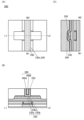
本発明の一態様は、トランジスタを有する半導体装置であって、トランジスタは、第1の酸化物と、第2の酸化物と、第1の導電体と、第2の導電体と、第3の導電体と、第1の絶縁体と、第2の絶縁体と、を有し、第1の酸化物は、第1の領域、第2の領域、および第1の領域と第2の領域とに接する第3の領域を有し、第1の領域は、第1の導電体と重畳し、第2の領域は、第2の導電体と重畳し、第3の領域は、第1の絶縁体、および第2の酸化物を介して、第3の導電体と重畳する領域を有し、第2の絶縁体は、第1の導電体の側面、第2の導電体の側面、および第3の領域を露出する開口を有し、第3の導電体は、第2の酸化物、および第1の絶縁体を介して、開口内に配置され、第1の酸化物は金属元素と、窒素と、を含み、金属元素は、インジウム(In)と、元素M(Mはアルミニウム(Al)、ガリウム(Ga)、イットリウム(Y)、または錫(Sn))と、亜鉛(Zn)と、であり、窒素は、酸素欠損内に取り込まれている、または、金属元素の原子と結合している。 One aspect of the present invention is a semiconductor device having a transistor, the transistor having a first oxide, a second oxide, a first conductor, a second conductor, a third conductor, a first insulator, and a second insulator, the first oxide having a first region, a second region, and a third region in contact with the first region and the second region, the first region overlapping with the first conductor, the second region overlapping with the second conductor, and the third region having a region overlapping with the third conductor via the first insulator and the second oxide. The second insulator has an opening exposing the side of the first conductor, the side of the second conductor, and the third region, and the third conductor is disposed in the opening via the second oxide and the first insulator, the first oxide includes a metal element and nitrogen, the metal element is indium (In), element M (M is aluminum (Al), gallium (Ga), yttrium (Y), or tin (Sn)), and zinc (Zn), and the nitrogen is incorporated into the oxygen vacancy or is bonded to an atom of the metal element.
本発明の一態様は、トランジスタを有する半導体装置であって、トランジスタは、第1の酸化物と、第2の酸化物と、第1の導電体と、第2の導電体と、第3の導電体と、第1の絶縁体と、第2の絶縁体と、第3の絶縁体と、を有し、第1の酸化物は、第1の領域、第2の領域、および第1の領域と第2の領域とに接する第3の領域を有し、第1の領域は、第1の導電体と重畳し、第2の領域は、第2の導電体と重畳し、第3の領域は、第1の絶縁体、および第2の酸化物を介して、第3の導電体と重畳する領域を有し、第2の絶縁体は、第3の絶縁体を介して、第1の導電体、および第2の導電体と重畳し、かつ、第1の導電体の側面、第2の導電体の側面、および第3の領域を露出する開口を有し、第3の導電体は、第3の絶縁体、第2の酸化物、および第1の絶縁体を介して、開口内に配置され、第1の酸化物は金属元素と、窒素と、を含み、金属元素は、インジウム(In)と、元素M(Mはアルミニウム(Al)、ガリウム(Ga)、イットリウム(Y)、または錫(Sn))と、亜鉛(Zn)と、であり、窒素は、酸素欠損内に取り込まれている、または、金属元素の原子と結合している。 One aspect of the present invention is a semiconductor device having a transistor, the transistor having a first oxide, a second oxide, a first conductor, a second conductor, a third conductor, a first insulator, a second insulator, and a third insulator, the first oxide having a first region, a second region, and a third region in contact with the first region and the second region, the first region overlapping with the first conductor, the second region overlapping with the second conductor, the third region having a region overlapping with the third conductor via the first insulator and the second oxide, and the second insulator being the third insulator. The third conductor overlaps the first conductor and the second conductor through the third insulator, and has an opening that exposes the side of the first conductor, the side of the second conductor, and the third region, and the third conductor is disposed in the opening through the third insulator, the second oxide, and the first insulator, and the first oxide includes a metal element and nitrogen, the metal element being indium (In), element M (M is aluminum (Al), gallium (Ga), yttrium (Y), or tin (Sn)), and zinc (Zn), and the nitrogen is incorporated into the oxygen vacancy or is bonded to an atom of the metal element.
上記半導体装置において、第1の酸化物は、セリウム(Ce)を含む。 In the above semiconductor device, the first oxide contains cerium (Ce).
本発明の一態様は、トランジスタを有する半導体装置であって、トランジスタは、第1の酸化物と、第2の酸化物と、第3の酸化物と、第4の酸化物と、第1の導電体と、第2の導電体と、第3の導電体と、第1の絶縁体と、第2の絶縁体と、を有し、第1の酸化物は、第1の領域、第2の領域、および第1の領域と第2の領域とに接する第3の領域を有し、第1の領域は、第3の酸化物を介して、第1の導電体と重畳し、第2の領域は、第4の酸化物を介して、第2の導電体と重畳し、第3の領域は、第1の絶縁体、および第2の酸化物を介して、第3の導電体と重畳する領域を有し、第2の絶縁体は、第3の領域を露出する開口を有し、開口の側面と、第1の導電体、または第2の導電体の側面は、同一平面上であり、第3の導電体は、第2の酸化物、および第1の絶縁体を介して、開口内に配置され、第1の酸化物は金属元素と、窒素と、を含み、金属元素は、インジウム(In)と、元素M(Mはアルミニウム(Al)、ガリウム(Ga)、イットリウム(Y)、または錫(Sn))と、亜鉛(Zn)と、であり、窒素は、酸素欠損内に取り込まれている、または、金属元素の原子と結合している。 One aspect of the present invention is a semiconductor device having a transistor, the transistor having a first oxide, a second oxide, a third oxide, a fourth oxide, a first conductor, a second conductor, a third conductor, a first insulator, and a second insulator, the first oxide having a first region, a second region, and a third region in contact with the first region and the second region, the first region overlapping with the first conductor via the third oxide, the second region overlapping with the second conductor via the fourth oxide, the third region overlapping with the third conductor via the first insulator and the second oxide. The second insulator has an opening exposing the third region, and the side of the opening is flush with the side of the first conductor or the second conductor. The third conductor is disposed in the opening via the second oxide and the first insulator. The first oxide contains a metal element and nitrogen, and the metal element is indium (In), element M (M is aluminum (Al), gallium (Ga), yttrium (Y), or tin (Sn)), and zinc (Zn). The nitrogen is incorporated in the oxygen vacancy or is bonded to an atom of the metal element.
本発明の一態様は、トランジスタを有する半導体装置であって、トランジスタは、第1の酸化物と、第2の酸化物と、第3の酸化物と、第4の酸化物と、第1の導電体と、第2の導電体と、第3の導電体と、第1の絶縁体と、第2の絶縁体と、第3の絶縁体と、を有し、第1の酸化物は、第1の領域、第2の領域、および第1の領域と第2の領域とに接する第3の領域を有し、第1の領域は、第3の酸化物を介して、第1の導電体と重畳し、第2の領域は、第4の酸化物を介して、第2の導電体と重畳し、第3の領域は、第1の絶縁体、および第2の酸化物を介して、第3の導電体と重畳する領域を有し、第2の絶縁体は、第3の絶縁体を介して、第1の導電体、および第2の導電体と重畳し、かつ、第1の導電体の側面、第2の導電体の側面、および第3の領域を露出する開口を有し、第3の導電体は、第3の絶縁体、第2の酸化物、および第1の絶縁体を介して、開口内に配置され、第1の酸化物は金属元素と、窒素と、を含み、金属元素は、インジウム(In)と、元素M(Mはアルミニウム(Al)、ガリウム(Ga)、イットリウム(Y)、または錫(Sn))と、亜鉛(Zn)と、であり、窒素は、酸素欠損内に取り込まれている、または、金属元素の原子と結合している。 One aspect of the present invention is a semiconductor device having a transistor, the transistor having a first oxide, a second oxide, a third oxide, a fourth oxide, a first conductor, a second conductor, a third conductor, a first insulator, a second insulator, and a third insulator, the first oxide having a first region, a second region, and a third region in contact with the first region and the second region, the first region overlaps with the first conductor through the third oxide, the second region overlaps with the second conductor through the fourth oxide, and the third region overlaps with the first insulator and the third conductor through the second oxide. The second insulator overlaps the first conductor and the second conductor through the third insulator, and has an opening exposing the side of the first conductor, the side of the second conductor, and the third region, and the third conductor is disposed in the opening through the third insulator, the second oxide, and the first insulator, and the first oxide includes a metal element and nitrogen, the metal element being indium (In), element M (M is aluminum (Al), gallium (Ga), yttrium (Y), or tin (Sn)), and zinc (Zn), and the nitrogen is incorporated in the oxygen vacancy or is bonded to an atom of the metal element.
上記半導体装置において、第3の酸化物、および第4の酸化物は、第1の酸化物よりも、セリウム(Ce)の含有量が多い。 In the above semiconductor device, the third oxide and the fourth oxide have a higher cerium (Ce) content than the first oxide.
上記半導体装置において、第1の酸化物のキャリア濃度は、5×1017cm-3未満である。 In the semiconductor device, the carrier concentration of the first oxide is less than 5×10 17 cm −3 .
上記半導体装置において、第1の酸化物において、窒素の原子数の比率が、1.2atomic%未満である。 In the above semiconductor device, the ratio of nitrogen atoms in the first oxide is less than 1.2 atomic %.
上記半導体装置において、第1の酸化物に対して電子を照射した場合において、電子の累積照射線量が3.6×10⁸e-/nm2以下である場合に、酸化物の構造変化が観察されない。 In the above semiconductor device, when the first oxide is irradiated with electrons, if the cumulative electron irradiation dose is 3.6×10 8 e − /nm 2 or less, no structural change of the oxide is observed.
本発明の一態様により、新規な半導体材料を提供することができる。また、良好な電気特性を有する半導体装置を提供することができる。また、信頼性が良好な半導体装置を提供することができる。 One aspect of the present invention can provide a new semiconductor material. It can also provide a semiconductor device with good electrical characteristics. It can also provide a semiconductor device with good reliability.
なお、これらの効果の記載は、他の効果の存在を妨げるものではない。なお、本発明の一態様は、これらの効果の全てを有する必要はない。なお、これら以外の効果は、明細書、図面、請求項などの記載から、自ずと明らかとなるものであり、明細書、図面、請求項などの記載から、これら以外の効果を抽出することが可能である。 Note that the description of these effects does not preclude the existence of other effects. Note that one embodiment of the present invention does not need to have all of these effects. Note that effects other than these will become apparent from the description in the specification, drawings, claims, etc., and it is possible to extract effects other than these from the description in the specification, drawings, claims, etc.
以下、実施の形態について図面を参照しながら説明する。ただし、実施の形態は多くの異なる形態で実施することが可能であり、趣旨およびその範囲から逸脱することなくその形態および詳細を様々に変更し得ることは当業者であれば容易に理解される。したがって、本発明は、以下の実施の形態の記載内容に限定して解釈されるものではない。 The following describes the embodiments with reference to the drawings. However, it will be readily understood by those skilled in the art that the embodiments can be implemented in many different forms, and that the forms and details can be modified in various ways without departing from the spirit and scope of the invention. Therefore, the present invention should not be interpreted as being limited to the description of the embodiments below.
また、図面において、大きさ、層の厚さ、または領域は、明瞭化のために誇張されている場合がある。よって、必ずしもそのスケールに限定されない。なお図面は、理想的な例を模式的に示したものであり、図面に示す形状または値などに限定されない。また、図面において、同一部分または同様な機能を有する部分には同一の符号を異なる図面間で共通して用い、その繰り返しの説明は省略する場合がある。また、同様の機能を指す場合には、ハッチパターンを同じくし、特に符号を付さない場合がある。 In addition, in the drawings, sizes, layer thicknesses, or areas may be exaggerated for clarity. Therefore, they are not necessarily limited to the scale. Note that the drawings are schematic representations of ideal examples, and are not limited to the shapes or values shown in the drawings. In addition, in the drawings, the same reference numerals may be used in common between different drawings for the same parts or parts having similar functions, and repeated explanations may be omitted. In addition, when referring to similar functions, the same hatch pattern may be used and no particular reference numeral may be used.
また、特に上面図(「平面図」ともいう。)や斜視図などにおいて、発明の理解を容易とするため、一部の構成要素の記載を省略する場合がある。また、一部の隠れ線などの記載を省略する場合がある。 In particular, in top views (also called "plan views") and oblique views, some components may be omitted to make the invention easier to understand. Some hidden lines may also be omitted.
また、本明細書等において、第1、第2等として付される序数詞は便宜上用いるものであり、工程順または積層順を示すものではない。そのため、例えば、「第1の」を「第2の」または「第3の」などと適宜置き換えて説明することができる。また、本明細書等に記載されている序数詞と、本発明の一態様を特定するために用いられる序数詞は一致しない場合がある。 In addition, in this specification, ordinal numbers such as first, second, etc. are used for convenience and do not indicate the order of processes or stacking. Therefore, for example, "first" can be appropriately replaced with "second" or "third" to explain. In addition, the ordinal numbers described in this specification and the ordinal numbers used to identify one aspect of the present invention may not match.
また、本明細書等において、「上に」、「下に」などの配置を示す語句は、構成同士の位置関係を、図面を参照して説明するために、便宜上用いている。また、構成同士の位置関係は、各構成を描写する方向に応じて適宜変化するものである。したがって、明細書で説明した語句に限定されず、状況に応じて適切に言い換えることができる。 In addition, in this specification, terms indicating arrangement such as "above" and "below" are used for convenience in order to explain the positional relationship between components with reference to the drawings. Furthermore, the positional relationship between components changes as appropriate depending on the direction in which each component is depicted. Therefore, the terms are not limited to those described in the specification, and can be rephrased appropriately depending on the situation.
例えば、本明細書等において、XとYとが接続されている、と明示的に記載されている場合は、XとYとが電気的に接続されている場合と、XとYとが機能的に接続されている場合と、XとYとが直接的に接続されている場合とが、本明細書等に開示されているものとする。したがって、所定の接続関係、例えば、図または文章に示された接続関係に限定されず、図または文章に示された以外の接続関係も、図または文章に開示されているものとする。 For example, when it is explicitly stated in this specification that X and Y are connected, the case where X and Y are electrically connected, the case where X and Y are functionally connected, and the case where X and Y are directly connected are considered to be disclosed in this specification. Therefore, it is not limited to a specific connection relationship, for example, a connection relationship shown in a figure or text, and connection relationships other than those shown in the figure or text are also considered to be disclosed in the figure or text.
ここで、X、Yは、対象物(例えば、装置、素子、回路、配線、電極、端子、導電膜、層、など)であるとする。 Here, X and Y are objects (e.g., devices, elements, circuits, wiring, electrodes, terminals, conductive films, layers, etc.).
本明細書において、酸化物、金属酸化物、化合物などを構成する元素の原子数比を示す場合、特段断りが無い限りは、その原子数比の近傍も含まれる場合がある。ここで、原子数比の近傍とは、各原子数を示す値の50%以上150%以下の値を含めるものとする。例えば、元素Aおよび元素Bの原子数比が[A]:[B]=2:1の場合、[A]の比率の近傍として、1以上3以下を含み、[B]の比率の近傍として、0.5以上1.5以下を含むものとする。また、原子数比の近傍とは、各原子数を示す値の80%以上120%以下の値を含めるものとする。例えば、元素Aおよび元素Bの原子数比が[A]:[B]=2:1の場合、[A]の比率の近傍として、1.6以上2.4以下を含み、[B]の比率の近傍として、0.8以上1.2以下を含むものとする。また、原子数比の近傍とは、各原子数を示す値の90%以上110%以下の値を含めるものとする。例えば、元素Aおよび元素Bの原子数比が[A]:[B]=2:1の場合、[A]の比率の近傍として、1.8以上2.2以下を含み、[B]の比率の近傍として、0.9以上1.1以下を含むものとする。 In this specification, when the atomic ratio of elements constituting an oxide, metal oxide, compound, etc. is indicated, the vicinity of the atomic ratio may also be included unless otherwise specified. Here, the vicinity of the atomic ratio includes values of 50% to 150% of the value indicating each atomic number. For example, when the atomic ratio of element A and element B is [A]:[B]=2:1, the vicinity of the ratio of [A] includes 1 to 3, and the vicinity of the ratio of [B] includes 0.5 to 1.5. In addition, the vicinity of the atomic ratio includes values of 80% to 120% of the value indicating each atomic number. For example, when the atomic ratio of element A and element B is [A]:[B]=2:1, the vicinity of the ratio of [A] includes 1.6 to 2.4, and the vicinity of the ratio of [B] includes 0.8 to 1.2. In addition, the vicinity of the atomic ratio includes values of 90% to 110% of the value indicating each atomic number. For example, if the atomic ratio of element A to element B is [A]:[B]=2:1, the vicinity of the ratio of [A] includes 1.8 or more and 2.2 or less, and the vicinity of the ratio of [B] includes 0.9 or more and 1.1 or less.
また、ソースやドレインの機能は、異なる極性のトランジスタを採用する場合や、回路動作において電流の方向が変化する場合などには入れ替わることがある。このため、本明細書等においては、ソースやドレインの用語は、入れ替えて用いることができる場合がある。 Furthermore, the functions of the source and drain may be interchangeable when transistors of different polarity are used, or when the direction of current changes during circuit operation. For this reason, in this specification and elsewhere, the terms source and drain may be used interchangeably.
なお、本明細書等において、酸化窒化シリコンとは、その組成として、窒素よりも酸素の含有量が多いものである。また、窒化酸化シリコンとは、その組成として、酸素よりも窒素の含有量が多いものである。 In this specification, silicon oxynitride refers to a material whose composition contains more oxygen than nitrogen. Silicon nitride oxide refers to a material whose composition contains more nitrogen than oxygen.
また、本明細書等において、「平行」とは、二つの直線が-10度以上10度以下の角度で配置されている状態をいう。したがって、-5度以上5度以下の場合も含まれる。また、「略平行」とは、二つの直線が-30度以上30度以下の角度で配置されている状態をいう。また、「垂直」とは、二つの直線が80度以上100度以下の角度で配置されている状態をいう。したがって、85度以上95度以下の場合も含まれる。また、「略垂直」とは、二つの直線が60度以上120度以下の角度で配置されている状態をいう。 In addition, in this specification, "parallel" refers to a state in which two straight lines are arranged at an angle of -10 degrees or more and 10 degrees or less. Therefore, it also includes cases in which the angle is -5 degrees or more and 5 degrees or less. "Approximately parallel" refers to a state in which two straight lines are arranged at an angle of -30 degrees or more and 30 degrees or less. "Perpendicular" refers to a state in which two straight lines are arranged at an angle of 80 degrees or more and 100 degrees or less. Therefore, it also includes cases in which the angle is 85 degrees or more and 95 degrees or less. "Approximately perpendicular" refers to a state in which two straight lines are arranged at an angle of 60 degrees or more and 120 degrees or less.
なお、本明細書において、バリア膜とは、水素などの不純物および酸素の透過を抑制する機能を有する膜のことであり、当該バリア膜に導電性を有する場合は、導電性バリア膜と呼ぶことがある。 In this specification, a barrier film is a film that has the function of suppressing the permeation of impurities such as hydrogen and oxygen, and if the barrier film has conductivity, it may be called a conductive barrier film.
また、本明細書等において、ノーマリーオフとは、ゲートに電位を印加しない、またはゲートに接地電位を与えたときに、トランジスタに流れるチャネル幅1μmあたりの電流が、室温において1×10-20A以下、85℃において1×10-18A以下、または125℃において1×10-16A以下であることをいう。 In addition, in this specification and the like, normally-off means that when no potential is applied to the gate or when a ground potential is applied to the gate, a current per 1 μm of channel width flowing in a transistor is 1×10 −20 A or less at room temperature, 1×10 −18 A or less at 85° C., or 1×10 −16 A or less at 125° C.
また、本明細書等では、オフ電流と同じ意味で、リーク電流と記載する場合がある。また、本明細書等において、オフ電流とは、例えば、トランジスタがオフ状態にあるときに、ソースとドレインとの間に流れる電流を指す場合がある。 In addition, in this specification, the term "leakage current" may be used to mean the same thing as "off-state current." In this specification, the term "off-state current" may refer to, for example, a current that flows between the source and drain when a transistor is in an off state.
本明細書等において、金属酸化物(metal oxide)とは、広い意味での金属の酸化物である。金属酸化物は、酸化物絶縁体、酸化物導電体(透明酸化物導電体を含む。)、酸化物半導体(Oxide Semiconductorまたは単にOSともいう)などに分類される。例えば、トランジスタの半導体層に金属酸化物を用いた場合、当該金属酸化物を酸化物半導体と呼称する場合がある。つまり、OSトランジスタと記載する場合においては、酸化物または酸化物半導体を有するトランジスタと換言することができる。 In this specification and the like, metal oxide is a metal oxide in a broad sense. Metal oxides are classified into oxide insulators, oxide conductors (including transparent oxide conductors), oxide semiconductors (also referred to as oxide semiconductors or simply OS), and the like. For example, when a metal oxide is used in the semiconductor layer of a transistor, the metal oxide may be referred to as an oxide semiconductor. In other words, when an OS transistor is referred to as a transistor having an oxide or an oxide semiconductor.
なお、本明細書等において、窒素を含む酸化物半導体も酸化物半導体と総称する場合がある。また、窒素を含む酸化物半導体を、酸窒化物半導体と呼称してもよい。 Note that in this specification and the like, oxide semiconductors containing nitrogen may also be collectively referred to as oxide semiconductors. Furthermore, oxide semiconductors containing nitrogen may also be referred to as oxynitride semiconductors.
(実施の形態1)
以下では、本発明の一態様である酸化物半導体について、図1乃至図4を用いて説明する。
(Embodiment 1)
An oxide semiconductor which is one embodiment of the present invention will be described below with reference to FIGS.
トランジスタは、チャネルが形成される領域(以下、チャネル形成領域ともいう。)に、酸化物半導体として機能する金属酸化物(以下、酸化物半導体ともいう。)を用いることが好ましい。チャネル形成領域に酸化物半導体を用いたトランジスタは、非導通状態においてリーク電流が極めて小さいため、低消費電力の半導体装置を提供できる。また、酸化物半導体は、スパッタリング法などを用いて成膜できるため、高集積型の半導体装置を構成するトランジスタに用いることができる。 It is preferable that a metal oxide (hereinafter also referred to as an oxide semiconductor) that functions as an oxide semiconductor is used in a region where a channel is formed (hereinafter also referred to as a channel formation region) of a transistor. A transistor using an oxide semiconductor in a channel formation region has an extremely small leakage current in a non-conducting state, and therefore a semiconductor device with low power consumption can be provided. In addition, an oxide semiconductor can be formed by a sputtering method or the like, and therefore can be used in transistors that constitute a highly integrated semiconductor device.
酸化物半導体をトランジスタのチャネル形成領域に用いる場合、キャリア濃度が低い、i型化(真性化)または実質的にi型化された酸化物半導体を用いることが好ましい。キャリア濃度が低い酸化物半導体をトランジスタのチャネル形成領域に用いることで、該トランジスタのオフ電流を小さく抑えることができる、または、該トランジスタの信頼性を向上させることができる。したがって、酸化物半導体のキャリア濃度を低減することは重要である。 When an oxide semiconductor is used in the channel formation region of a transistor, it is preferable to use an oxide semiconductor that has a low carrier concentration and is i-type (intrinsic) or substantially i-type. By using an oxide semiconductor with a low carrier concentration in the channel formation region of a transistor, the off-state current of the transistor can be reduced or the reliability of the transistor can be improved. Therefore, it is important to reduce the carrier concentration of the oxide semiconductor.
酸化物半導体のキャリア(n型半導体の場合は電子)は、酸素欠損内に取り込まれた水素、別言すると、酸素のサイトに位置した水素(ここでは、VOHまたはHOと表記する。)によって主に形成される。つまり、酸素欠損内に取り込まれた水素は、ドナーとして機能する。したがって、水素が酸素欠損内に取り込まれることで、トランジスタのしきい値電圧がマイナス側へシフトし、ノーマリーオンの特性となる。ここで、ノーマリーオンとは、ゲート電極に電圧を印加しなくてもチャネルが存在し、トランジスタに電流が流れてしまう状態のことをいう。なお、酸素欠損内に取り込まれた水素とキャリア濃度の関係については、後述する。 Carriers in an oxide semiconductor (electrons in the case of an n-type semiconductor) are mainly formed by hydrogen trapped in the oxygen vacancies, in other words, hydrogen located at oxygen sites (here, represented as V O H or H O ). That is, hydrogen trapped in the oxygen vacancies functions as a donor. Therefore, when hydrogen is trapped in the oxygen vacancies, the threshold voltage of the transistor shifts to the negative side, resulting in a normally-on characteristic. Here, normally-on refers to a state in which a channel exists and a current flows through the transistor even when no voltage is applied to the gate electrode. The relationship between hydrogen trapped in the oxygen vacancies and the carrier concentration will be described later.
酸化物半導体のキャリア濃度を低減するには、酸素欠損内に取り込まれた水素の量を低減するとよい。酸素欠損内に取り込まれた水素の量を低減することで、酸化物半導体をi型化または実質的にi型化することができる。なお、酸素欠損内に取り込まれた水素の量を低減するには、酸化物半導体に存在する酸素欠損または水素を低減するとよい。 In order to reduce the carrier concentration of an oxide semiconductor, it is preferable to reduce the amount of hydrogen trapped in the oxygen vacancies. By reducing the amount of hydrogen trapped in the oxygen vacancies, the oxide semiconductor can be made i-type or substantially i-type. Note that in order to reduce the amount of hydrogen trapped in the oxygen vacancies, it is preferable to reduce the oxygen vacancies or hydrogen present in the oxide semiconductor.
酸素欠損内に取り込まれた水素の量を低減するには、酸化物半導体に存在する酸素欠損の量を低減するとよい。酸化物半導体に存在する酸素欠損の量を低減することで、酸化物半導体に存在する水素が酸素欠損内に取り込まれるのを防ぐことができる。酸素欠損を低減する方法として、例えば、酸化物半導体に酸素を供給する方法が挙げられる。 In order to reduce the amount of hydrogen trapped in the oxygen vacancies, it is advisable to reduce the amount of oxygen vacancies present in the oxide semiconductor. By reducing the amount of oxygen vacancies present in the oxide semiconductor, it is possible to prevent hydrogen present in the oxide semiconductor from being trapped in the oxygen vacancies. One method for reducing oxygen vacancies is, for example, to supply oxygen to the oxide semiconductor.
しかしながら、酸化物半導体に供給された酸素により、全ての酸素欠損が補償されるとは限らない。酸素欠損の大きさは、酸素原子の大きさよりも小さくなる場合があるためである。酸素欠損の大きさが酸素原子の大きさよりも小さい場合、酸化物半導体に供給された酸素が酸素欠損の近傍まで拡散しても、酸素欠損を補償し難くなる。なお、酸素欠損の大きさについては、後述する。 However, the oxygen supplied to the oxide semiconductor does not necessarily compensate for all oxygen vacancies. This is because the size of the oxygen vacancies may be smaller than the size of the oxygen atoms. If the size of the oxygen vacancies is smaller than the size of the oxygen atoms, it is difficult to compensate for the oxygen vacancies even if the oxygen supplied to the oxide semiconductor diffuses to the vicinity of the oxygen vacancies. The size of the oxygen vacancies will be described later.
また、酸素欠損内に取り込まれた水素の量を低減するには、酸化物半導体に存在する水素の量、あるいは酸化物半導体近傍に存在する水素の量を低減するとよい。酸化物半導体に存在する水素は、酸素欠損内に位置する以外に、格子サイトでないところに位置する。水素原子の大きさは、酸素原子の大きさよりも小さいことから、格子サイトでないところに位置する水素は、酸化物半導体中を拡散しやすい。該水素は、酸素欠損の近傍まで拡散すると、酸素欠損内に取り込まれる場合がある。したがって、酸素欠損内に取り込まれた水素の量を低減するには、酸素欠損内に位置する水素、および格子サイトでないところに位置する水素を低減する必要がある。 In addition, in order to reduce the amount of hydrogen taken up in the oxygen vacancies, it is advisable to reduce the amount of hydrogen present in the oxide semiconductor or the amount of hydrogen present near the oxide semiconductor. Hydrogen present in the oxide semiconductor is located not only in the oxygen vacancies but also in places other than the lattice sites. Since the size of a hydrogen atom is smaller than the size of an oxygen atom, hydrogen located in places other than the lattice sites is likely to diffuse in the oxide semiconductor. When the hydrogen diffuses to the vicinity of the oxygen vacancies, it may be taken up in the oxygen vacancies. Therefore, in order to reduce the amount of hydrogen taken up in the oxygen vacancies, it is necessary to reduce the hydrogen located in the oxygen vacancies and the hydrogen located in places other than the lattice sites.
酸化物半導体に存在する水素の量を低減するためには、脱水素化処理または脱水処理を行うことが有効である。しかしながら、当該処理を行うと、酸化物半導体中に酸素欠損が形成される。さらに、該処理では加熱処理を行うため、格子サイトでないところに位置する水素が酸化物半導体中を拡散する。該水素は、形成された酸素欠損の近傍まで拡散すると、酸素欠損内に取り込まれる場合がある。結果として、酸素欠損内に取り込まれた水素の量を低減することができない可能性がある。 In order to reduce the amount of hydrogen present in an oxide semiconductor, it is effective to perform a dehydrogenation treatment or a dehydration treatment. However, when this treatment is performed, oxygen vacancies are formed in the oxide semiconductor. Furthermore, since this treatment involves heat treatment, hydrogen that is not located at a lattice site diffuses into the oxide semiconductor. If the hydrogen diffuses to the vicinity of the formed oxygen vacancies, it may be taken up into the oxygen vacancies. As a result, it may not be possible to reduce the amount of hydrogen taken up into the oxygen vacancies.
酸化物半導体近傍に存在する水素の量を低減するためには、酸化物半導体近傍に位置する絶縁体または導電体の水素を低減すればよい。例えば、酸化物半導体近傍に絶縁体が位置する場合、当該絶縁体中の水素が酸化物半導体に拡散し、酸化物半導体中の酸素欠損内に取り込まれる場合がある。 In order to reduce the amount of hydrogen present near the oxide semiconductor, it is necessary to reduce hydrogen in an insulator or conductor located near the oxide semiconductor. For example, when an insulator is located near the oxide semiconductor, hydrogen in the insulator may diffuse into the oxide semiconductor and be taken into oxygen vacancies in the oxide semiconductor.
以上より、酸化物半導体に存在する酸素欠損および水素の量を同時に制御するのは困難である。 For these reasons, it is difficult to simultaneously control the amount of oxygen vacancies and hydrogen present in an oxide semiconductor.
そこで、酸化物半導体に窒素(N)を導入する。そうすることで、窒素が酸化物半導体に存在する酸素欠損内に取り込まれる場合がある。以降では、酸素欠損内に取り込まれた窒素をVONあるいはNOと表記する場合がある。酸素欠損内に取り込まれた窒素はキャリアを生成しない、つまり、酸素欠損内に取り込まれた窒素はドナーとして機能しない。したがって、窒素が酸素欠損内に取り込まれることで、酸化物半導体中のキャリア濃度を低減することができ、チャネル形成領域に当該酸化物半導体を用いたトランジスタをノーマリーオフの特性とすることができる。なお、酸素欠損内に取り込まれた窒素がキャリアを生成しないことについては後述する。 Therefore, nitrogen (N) is introduced into the oxide semiconductor. In this case, the nitrogen may be taken into oxygen vacancies present in the oxide semiconductor. Hereinafter, the nitrogen taken into the oxygen vacancies may be expressed as V O N or N O. The nitrogen taken into the oxygen vacancies does not generate carriers, that is, the nitrogen taken into the oxygen vacancies does not function as a donor. Therefore, by taking in the nitrogen into the oxygen vacancies, the carrier concentration in the oxide semiconductor can be reduced, and a transistor using the oxide semiconductor in a channel formation region can have normally-off characteristics. Note that the fact that the nitrogen taken into the oxygen vacancies does not generate carriers will be described later.
酸素欠損内に取り込まれた窒素の周りには、酸化物半導体を構成している金属元素の原子が存在する。つまり、酸素欠損内に取り込まれた窒素は、当該酸素欠損近傍に位置する金属原子と結合している。窒素原子と金属原子の結合は、例えば、X線光電子分光法(XPS:X-ray Photoelectron Spectroscopy)を用いて評価することができる。なお、酸化物半導体に含まれる窒素の量によっては、窒素原子と金属原子の結合を示すピークが検出されない場合がある。 Atoms of the metal element constituting the oxide semiconductor are present around the nitrogen incorporated into the oxygen vacancy. In other words, the nitrogen incorporated into the oxygen vacancy is bonded to a metal atom located near the oxygen vacancy. The bond between the nitrogen atom and the metal atom can be evaluated, for example, using X-ray photoelectron spectroscopy (XPS). Note that, depending on the amount of nitrogen contained in the oxide semiconductor, a peak indicating the bond between the nitrogen atom and the metal atom may not be detected.
また、酸化物半導体に窒素を導入することで、酸素欠損内に取り込まれた水素の量を低減することができる。金属原子と水素原子との結合エネルギーと比べて、金属原子と窒素原子との結合エネルギーは大きい傾向がある。よって、酸素欠損内に取り込まれた水素は窒素と置換しやすく、酸素欠損内に取り込まれた窒素は水素と置換しにくい。したがって、酸化物半導体に導入した窒素が、酸素欠損内に取り込まれた水素と置換することで、酸素欠損内に取り込まれた水素の量を低減することができる。さらに、酸素欠損内に取り込まれた水素と比べて、酸素欠損内に取り込まれた窒素は熱などに対して安定である。 In addition, by introducing nitrogen into the oxide semiconductor, the amount of hydrogen taken up in the oxygen vacancies can be reduced. The bond energy between a metal atom and a nitrogen atom tends to be greater than the bond energy between a metal atom and a hydrogen atom. Therefore, hydrogen taken up in the oxygen vacancies is easily replaced by nitrogen, but nitrogen taken up in the oxygen vacancies is difficult to replace by hydrogen. Therefore, by replacing the hydrogen taken up in the oxygen vacancies with nitrogen introduced into the oxide semiconductor, the amount of hydrogen taken up in the oxygen vacancies can be reduced. Furthermore, compared to hydrogen taken up in the oxygen vacancies, nitrogen taken up in the oxygen vacancies is more stable against heat and the like.
さらに、窒素が酸素欠損内に取り込まれることで、酸素欠損が拡散することを抑制することができる。酸素欠損は、半導体装置の製造工程における熱処理により拡散する場合がある。窒素が酸素欠損内に取り込まれることで、窒素が酸素欠損近傍に位置する金属原子と結合し、該酸素欠損が拡散することを抑制することができる。酸素欠損の拡散を抑制することで、酸素欠損および酸素欠損内に取り込まれた水素の存在する領域が拡大することを抑制することができる。なお、本明細書中では、窒素が酸素欠損内に取り込まれることで、酸素欠損の拡散を抑制することを、凍結(freezing)と呼ぶ場合がある。 Furthermore, by incorporating nitrogen into the oxygen vacancy, it is possible to suppress the diffusion of the oxygen vacancy. The oxygen vacancy may diffuse due to heat treatment in the manufacturing process of the semiconductor device. By incorporating nitrogen into the oxygen vacancy, the nitrogen bonds with metal atoms located near the oxygen vacancy, and it is possible to suppress the diffusion of the oxygen vacancy. By suppressing the diffusion of the oxygen vacancy, it is possible to suppress the expansion of the oxygen vacancy and the region where hydrogen incorporated into the oxygen vacancy exists. Note that in this specification, the suppression of the diffusion of the oxygen vacancy by incorporating nitrogen into the oxygen vacancy may be referred to as freezing.
以上のように、酸化物半導体に窒素を導入することで、該酸化物半導体のキャリア濃度を低くすることができる。該酸化物半導体をトランジスタのチャネル形成領域に用いることで、該トランジスタのオフ電流を小さく抑えることができる、または、該トランジスタの信頼性を向上させることができる。さらに、該酸化物半導体中の酸素欠損および酸素欠損内に取り込まれた窒素は拡散しにくいため、該酸化物半導体を用いたトランジスタは、サーマルバジェットに対して安定であり、設計の自由度を高めることができる。サーマルバジェットとは、半導体装置の製造工程において、該半導体装置に加える温度の時間積分値のことをいう。 As described above, by introducing nitrogen into an oxide semiconductor, the carrier concentration of the oxide semiconductor can be reduced. By using the oxide semiconductor in a channel formation region of a transistor, the off-state current of the transistor can be reduced or the reliability of the transistor can be improved. Furthermore, since oxygen vacancies in the oxide semiconductor and nitrogen taken into the oxygen vacancies are difficult to diffuse, a transistor using the oxide semiconductor is stable against a thermal budget and can increase the degree of freedom in design. The thermal budget refers to the time integral value of the temperature applied to the semiconductor device during the manufacturing process of the semiconductor device.
酸化物半導体中の窒素濃度を制御することで、金属酸化物のキャリア濃度を1×1018cm-3未満、好ましくは1×1017cm-3未満にすることができ、さらには1×1016cm-3以下になりうる。なお、酸化物半導体のキャリア濃度は、Hall効果測定により評価することができる。 By controlling the nitrogen concentration in the oxide semiconductor, the carrier concentration of the metal oxide can be reduced to less than 1×10 18 cm -3 , preferably less than 1×10 17 cm -3 , and further to 1×10 16 cm -3 or less. Note that the carrier concentration of the oxide semiconductor can be evaluated by Hall effect measurement.
酸化物半導体中の窒素濃度は、窒素を導入してない酸化物半導体のキャリア濃度と同等またはそれ以上であることが好ましい。キャリア濃度を低くするには、酸素欠損内に取り込まれた水素の量を減らすことが有効である。酸化物半導体に導入された窒素は、酸素欠損内に取り込まれた水素と置換しやすい。しかしながら、導入した窒素の全てが、酸素欠損内に取り込まれた水素と置換するとは限らない。したがって、酸化物半導体中の窒素濃度は、窒素を導入してない酸化物半導体のキャリア濃度と同等またはそれ以上であることが好ましい。 The nitrogen concentration in the oxide semiconductor is preferably equal to or higher than the carrier concentration of an oxide semiconductor into which nitrogen is not introduced. In order to lower the carrier concentration, it is effective to reduce the amount of hydrogen taken up in the oxygen vacancies. Nitrogen introduced into the oxide semiconductor is likely to replace the hydrogen taken up in the oxygen vacancies. However, not all of the introduced nitrogen will necessarily replace the hydrogen taken up in the oxygen vacancies. Therefore, it is preferable that the nitrogen concentration in the oxide semiconductor is equal to or higher than the carrier concentration of an oxide semiconductor into which nitrogen is not introduced.
また、酸化物半導体中の窒素濃度は、酸化物半導体中の水素濃度と同程度またはそれ以上であることが好ましい。酸化物半導体に導入された窒素は、酸素欠損内に取り込まれた水素と置換しやすい。よって、導入する窒素の量が酸素欠損内に取り込まれた水素の量よりも多いことで、酸素欠損内に取り込まれた水素の量を減らすことができる。さらに、格子サイトでないところに位置する水素が酸素欠損内に取り込まれるのを抑制するために、格子サイトでないところに位置する水素の量を低減した方が好ましい。したがって、酸化物半導体中の窒素濃度は、酸化物半導体中の水素濃度より高いことが好ましい。なお、格子サイトでないところに位置する水素は、酸素欠損内に取り込まれた窒素と結合してもキャリアを生成しない。したがって、酸化物半導体中の窒素濃度は、酸化物半導体中の水素濃度と同程度であってもよい。 In addition, the nitrogen concentration in the oxide semiconductor is preferably equal to or higher than the hydrogen concentration in the oxide semiconductor. Nitrogen introduced into the oxide semiconductor is easily replaced with hydrogen taken into the oxygen vacancies. Therefore, the amount of hydrogen taken into the oxygen vacancies can be reduced by introducing a larger amount of nitrogen than the amount of hydrogen taken into the oxygen vacancies. Furthermore, in order to suppress hydrogen located at non-lattice sites from being taken into the oxygen vacancies, it is preferable to reduce the amount of hydrogen located at non-lattice sites. Therefore, the nitrogen concentration in the oxide semiconductor is preferably higher than the hydrogen concentration in the oxide semiconductor. Note that hydrogen located at non-lattice sites does not generate carriers even when bonded with nitrogen taken into the oxygen vacancies. Therefore, the nitrogen concentration in the oxide semiconductor may be equal to the hydrogen concentration in the oxide semiconductor.
酸化物半導体中の窒素濃度は、例えば、1×10¹⁸atoms/cm3以上4×1021atoms/cm3以下が好ましい。さらには、1×1019atoms/cm3以上2×1021atoms/cm3以下が好ましい。さらには、5×1019atoms/cm3以上1×1021atoms/cm3未満が好ましい。 The nitrogen concentration in the oxide semiconductor is, for example, preferably greater than or equal to 1×10 18 atoms/cm 3 and less than or equal to 4×10 21 atoms/cm 3 , more preferably greater than or equal to 1×10 19 atoms/cm 3 and less than or equal to 2×10 21 atoms/cm 3 , and even more preferably greater than or equal to 5×10 19 atoms/cm 3 and less than 1×10 21 atoms/cm 3 .
または、酸化物半導体中の窒素の原子数の比率は、0.001atomic%以上5atomic%以下が好ましい。さらには、0.01atomic%以上3atomic%以下が好ましい。さらには、0.05atomic%以上1.2atomic%未満が好ましい。本明細書等において、窒素の原子数の比率[atomic%]は、酸化物半導体を構成する金属元素、酸素、窒素それぞれの原子数の合計に対する、窒素の原子数の比率を示す。 Alternatively, the ratio of the number of nitrogen atoms in the oxide semiconductor is preferably 0.001 atomic% or more and 5 atomic% or less. Further, it is more preferably 0.01 atomic% or more and 3 atomic% or less. Furthermore, it is more preferably 0.05 atomic% or more and less than 1.2 atomic%. In this specification and the like, the ratio of the number of nitrogen atoms [atomic %] indicates the ratio of the number of nitrogen atoms to the total number of atoms of the metal element, oxygen, and nitrogen that constitute the oxide semiconductor.
窒素が導入された酸化物半導体は、結晶性を有することが好ましい。該酸化物半導体が結晶性を有することで、酸化物半導体としての物理的性質が安定するため、熱に強く、信頼性が高い酸化物半導体を提供することができる。 The oxide semiconductor into which nitrogen has been introduced is preferably crystalline. When the oxide semiconductor has crystallinity, the physical properties of the oxide semiconductor are stable, making it possible to provide an oxide semiconductor that is resistant to heat and highly reliable.
酸化物半導体の結晶性としては、例えば、X線回折(XRD:X-Ray Diffraction)を用いて分析する、あるいは、透過型電子顕微鏡(TEM:Transmission Electron Microscope)を用いて分析することで解析することができる。または、酸化物半導体の結晶性としては、電子線回折で評価することができる。例えば、電子線回折パターンにおいて、リング状に輝度の高い領域、およびリング状に輝度の高い領域内に、複数のスポットが観察される場合がある。 The crystallinity of the oxide semiconductor can be analyzed, for example, by X-ray diffraction (XRD) or a transmission electron microscope (TEM). Alternatively, the crystallinity of the oxide semiconductor can be evaluated by electron diffraction. For example, in an electron diffraction pattern, a ring-shaped region of high brightness and multiple spots within the ring-shaped region of high brightness may be observed.
また、窒素を導入した酸化物半導体は、該酸化物半導体の構造が安定であることが好ましい。構造が安定である酸化物半導体とは、例えば、電子顕微鏡観察時の電子線照射によって結晶化が起こらない、または結晶構造が損なわれない酸化物半導体のことをいう。酸化物半導体に窒素を導入することでキャリア濃度を低減させることが可能になる一方、窒素を導入し過ぎると、酸化物半導体の構造が不安定になる場合がある。不安定な構造の酸化物半導体をトランジスタのチャネル形成領域に用いると、該トランジスタの動作や該トランジスタが発する熱などに伴い、進行性不良を引き起こす原因となるため、酸化物半導体の構造が安定であることは半導体装置の信頼性にとって重要である。 In addition, it is preferable that the structure of the oxide semiconductor into which nitrogen is introduced is stable. An oxide semiconductor with a stable structure refers to an oxide semiconductor that does not crystallize or does not lose its crystal structure when irradiated with an electron beam during observation under an electron microscope, for example. By introducing nitrogen into an oxide semiconductor, it is possible to reduce the carrier concentration, but if too much nitrogen is introduced, the structure of the oxide semiconductor may become unstable. If an oxide semiconductor with an unstable structure is used in the channel formation region of a transistor, progressive defects may occur due to the operation of the transistor or the heat generated by the transistor, and therefore it is important for the reliability of a semiconductor device that the oxide semiconductor has a stable structure.
また、酸素欠損内に取り込まれた窒素は、格子サイトでないところに位置する水素と結合する場合がある。酸化物半導体に存在する酸素および窒素は、それぞれ-2価、-3価となりやすい。酸素欠損内に取り込まれた窒素は、酸素原子と置換した窒素とみなすことができる。そのため、酸素欠損内に取り込まれた窒素は電子が一つ足りない状態、つまり、不対電子を有すると推定される。そこで、酸素欠損内に取り込まれた窒素は、格子サイトでないところに位置する水素と結合することで、該窒素および該水素が安定化すると推測される。さらに、酸素欠損内に取り込まれた窒素と結合した水素は、キャリアを生成しないと推測される。 In addition, nitrogen taken into the oxygen vacancy may bond with hydrogen located at a position other than the lattice site. Oxygen and nitrogen present in oxide semiconductors tend to be -2 and -3 valent, respectively. Nitrogen taken into the oxygen vacancy can be considered as nitrogen substituted for an oxygen atom. Therefore, it is presumed that the nitrogen taken into the oxygen vacancy is missing one electron, that is, has an unpaired electron. Therefore, it is presumed that the nitrogen taken into the oxygen vacancy bonds with hydrogen located at a position other than the lattice site, stabilizing the nitrogen and hydrogen. Furthermore, it is presumed that the hydrogen that bonds with the nitrogen taken into the oxygen vacancy does not generate carriers.
また、窒素を含む酸化物半導体に+4価となりうる原子を添加することで、該酸化物半導体のキャリア濃度を調整することができる。+4価となりうる原子として、セリウム(Ce)、プラセオジム(Pr)、ネオジム(Nd)、テルビウム(Tb)、ジスプロシウム(Dy)などがある。特に、セリウムは、インジウム(In)のイオン半径とほぼ同じであることから、酸化物半導体のインジウムと置き換わりやすいと推測される。+4価のセリウムが、+3価のインジウムと置き換わることで、電子が一つ余る、つまり、キャリアが生成される。したがって、+4価となりうる原子を添加する量を調整することにより、回路設計にあわせて、要求に見合う電気特性を有する半導体装置を容易に提供することができる。 In addition, by adding an atom that can become +4 to a nitrogen-containing oxide semiconductor, the carrier concentration of the oxide semiconductor can be adjusted. Examples of atoms that can become +4 include cerium (Ce), praseodymium (Pr), neodymium (Nd), terbium (Tb), and dysprosium (Dy). In particular, since cerium has almost the same ionic radius as indium (In), it is presumed that it is easy to replace indium in the oxide semiconductor. When +4 cerium replaces +3 indium, one extra electron is generated, that is, a carrier is generated. Therefore, by adjusting the amount of atoms that can become +4 to be added, a semiconductor device having electrical characteristics that meet the requirements can be easily provided in accordance with the circuit design.
<酸素欠損内に取り込まれた水素とキャリア濃度の関係>
ここでは、酸化物半導体のキャリア(電子)は、酸素欠損内に取り込まれた水素(VOHまたはHOと呼ぶ場合がある。)によって主に生成されることを、図1を用いて説明する。具体的には、酸化物半導体を成膜した試料に対してHall効果測定および電子スピン共鳴(ESR:Electron Spin Resonance)測定を行い、酸素欠損内に取り込まれた水素とキャリア濃度の関係について調査した。
<Relationship between hydrogen trapped in oxygen vacancies and carrier concentration>
Here, it will be described with reference to Fig. 1 that carriers (electrons) in an oxide semiconductor are mainly generated by hydrogen (sometimes referred to as V O H or H O ) trapped in oxygen vacancies. Specifically, Hall effect measurement and electron spin resonance (ESR) measurement were performed on a sample in which an oxide semiconductor film was formed, and the relationship between hydrogen trapped in the oxygen vacancies and the carrier concentration was investigated.
以下に、作製した試料A1乃至試料A17について説明する。 The following describes the samples A1 to A17 that were prepared.
まず、石英基板上に、スパッタリング法によって、酸化物半導体を35nmの膜厚で成膜した。酸化物半導体は、In:Ga:Zn=1:1:1[原子数比]のIn-Ga-Zn酸化物ターゲットを用いて、アルゴンガス流量30sccm、酸素ガス流量15sccm、圧力0.7Pa、基板とターゲットとの間の距離60nm、直流電源0.5kW、基板温度300℃の条件にて成膜した。 First, an oxide semiconductor was deposited on a quartz substrate by sputtering to a thickness of 35 nm. The oxide semiconductor was deposited using an In-Ga-Zn oxide target with an atomic ratio of In:Ga:Zn = 1:1:1 under the following conditions: argon gas flow rate of 30 sccm, oxygen gas flow rate of 15 sccm, pressure of 0.7 Pa, distance between substrate and target of 60 nm, DC power supply of 0.5 kW, and substrate temperature of 300°C.
次に、窒素を含む雰囲気にて温度400℃、1時間の加熱処理を行った。次に、酸素を含む雰囲気にて温度400℃、1時間の加熱処理を行った。 Next, a heat treatment was performed at 400°C for 1 hour in a nitrogen-containing atmosphere. Next, a heat treatment was performed at 400°C for 1 hour in an oxygen-containing atmosphere.
次に、水素ガス流量500sccm、圧力133Paの、水素を含む雰囲気(以下、水素雰囲気という。)にて1時間の加熱処理を行い、試料A1乃至試料A17を作製した。なお、該加熱処理時の温度は、試料A1が加熱処理無し、試料A2が100℃、試料A3が125℃、試料A4が150℃、試料A5が160℃、試料A6が170℃、試料A7が180℃、試料A8が190℃、試料A9が200℃、試料A10が225℃、試料A11が250℃、試料A12が275℃、試料A13が300℃、試料A14が325℃、試料A15が350℃、試料A16が375℃、試料A17が400℃とした。 Next, a heat treatment was performed for 1 hour in a hydrogen-containing atmosphere (hereinafter referred to as a hydrogen atmosphere) with a hydrogen gas flow rate of 500 sccm and a pressure of 133 Pa to prepare samples A1 to A17. The temperatures during the heat treatment were as follows: sample A1 was not heated, sample A2 was 100°C, sample A3 was 125°C, sample A4 was 150°C, sample A5 was 160°C, sample A6 was 170°C, sample A7 was 180°C, sample A8 was 190°C, sample A9 was 200°C, sample A10 was 225°C, sample A11 was 250°C, sample A12 was 275°C, sample A13 was 300°C, sample A14 was 325°C, sample A15 was 350°C, sample A16 was 375°C, and sample A17 was 400°C.
以上により、試料A1乃至試料A17を作製した。 As a result of the above, samples A1 to A17 were prepared.
上記の方法で作製した試料A1乃至試料17に対してHall効果測定を行い、酸化物半導体のキャリア濃度を算出した。ここで、Hall効果測定とは、電流の流れている対象物に、電流の向きに対して垂直に磁場をかけることによって、電流と磁場の双方に垂直な方向に起電力が現れるHall効果を利用して、キャリア密度、移動度および抵抗率などの電気特性を測定する方法である。ここでは、Van der Pauw法を用いたHall効果測定を行った。なお、Hall効果測定には、株式会社東陽テクニカ製ResiTestを用いた。 Hall effect measurements were performed on samples A1 to 17 prepared by the above method, and the carrier concentration of the oxide semiconductor was calculated. Here, the Hall effect measurement is a method of measuring electrical properties such as carrier density, mobility, and resistivity by applying a magnetic field perpendicular to the direction of the current to an object through which a current flows, thereby utilizing the Hall effect, in which an electromotive force appears in a direction perpendicular to both the current and the magnetic field. Here, the Hall effect measurement was performed using the Van der Pauw method. Note that ResiTest manufactured by Toyo Corporation was used for the Hall effect measurement.
図1に、水素雰囲気における加熱処理時の温度に対する、酸化物半導体のキャリア濃度の推移を示す。図1の横軸は、水素雰囲気における加熱処理時の温度[℃]であり、図1の第1の縦軸は、酸化物半導体のキャリア濃度[cm-3]である。図1では、酸化物半導体のキャリア濃度の測定値を菱形でプロットしている。図1から、水素雰囲気における加熱処理時の温度が高いほど、酸化物半導体のキャリア濃度が高くなることが分かった。 Fig. 1 shows the change in carrier concentration of an oxide semiconductor with respect to the temperature during heat treatment in a hydrogen atmosphere. The horizontal axis of Fig. 1 is the temperature [°C] during heat treatment in a hydrogen atmosphere, and the first vertical axis of Fig. 1 is the carrier concentration [cm -3 ] of the oxide semiconductor. In Fig. 1, the measured values of the carrier concentration of the oxide semiconductor are plotted as diamonds. It is clear from Fig. 1 that the higher the temperature during heat treatment in a hydrogen atmosphere, the higher the carrier concentration of the oxide semiconductor.
次に、試料A1乃至試料A17について、下記の条件でESR測定を行った。測定温度を室温とし、9.15GHzの高周波電力(マイクロ波パワー)を20mWとし、磁場の向きは作製した試料の膜表面と平行とした。なお、酸化物半導体が酸素欠損内に取り込まれた水素を有すると、ESR測定にてg値が1.93近傍に対称性を有する信号が現れる。よって、g値が1.93近傍に現れる信号より算出したスピン密度(以降、スピン密度(g値=1.93)と表記する。)が高いほど酸素欠損内に取り込まれた水素の量が多いといえる。なお、スピン密度(g値=1.93)の算出下限は、1.0×10¹⁷spins/cm3である。 Next, ESR measurements were performed on Samples A1 to A17 under the following conditions. The measurement temperature was room temperature, the 9.15 GHz high-frequency power (microwave power) was 20 mW, and the magnetic field was parallel to the film surface of the prepared sample. Note that when an oxide semiconductor has hydrogen trapped in oxygen vacancies, a signal having symmetry appears at a g-value of about 1.93 in the ESR measurement. Thus, it can be said that the higher the spin density calculated from the signal that appears at a g-value of about 1.93 (hereinafter referred to as spin density (g-value=1.93)), the greater the amount of hydrogen trapped in the oxygen vacancies. Note that the lower limit of the calculation of the spin density (g-value=1.93) is 1.0×10 17 spins/cm 3 .
図1に、水素雰囲気における加熱処理時の温度に対する、酸化物半導体のスピン密度(g値=1.93)の推移を示す。図1の第2の縦軸は、酸化物半導体のスピン密度(g値=1.93)[spins/cm3]である。図1では、スピン密度(g値=1.93)の算出値を丸でプロットしている。図1から、水素雰囲気における加熱処理時の温度が高いほど、酸化物半導体のスピン密度(g値=1.93)が高くなることが分かった。換言すると、水素雰囲気における加熱処理時の温度が高いほど、酸素欠損内に取り込まれた水素が増えることが分かった。なお、試料A16および試料A17では、g値が1.93近傍に現れる信号がブロードニングしたため、試料A16および試料A17のスピン密度を算出していない。 FIG. 1 shows the transition of the spin density (g value=1.93) of the oxide semiconductor with respect to the temperature during heat treatment in a hydrogen atmosphere. The second vertical axis in FIG. 1 is the spin density (g value=1.93) [spins/cm 3 ] of the oxide semiconductor. In FIG. 1 , the calculated values of the spin density (g value=1.93) are plotted with circles. From FIG. 1 , it was found that the higher the temperature during heat treatment in a hydrogen atmosphere, the higher the spin density (g value=1.93) of the oxide semiconductor. In other words, it was found that the higher the temperature during heat treatment in a hydrogen atmosphere, the more hydrogen was taken into the oxygen vacancies. Note that, in the samples A16 and A17, the signal appearing near the g value of 1.93 was broadened, and therefore the spin densities of the samples A16 and A17 were not calculated.
以上より、水素雰囲気における加熱処理時の温度が高いほど、酸化物半導体のキャリア濃度が高く、酸素欠損内に取り込まれた水素が増えることが分かった。そこで、キャリア濃度と酸素欠損内に取り込まれた水素の量との関係に注目すると、酸化物半導体のキャリア濃度が高いほど、酸素欠損内に取り込まれた水素が増える、つまり、酸化物半導体のキャリア濃度は、酸素欠損内に取り込まれた水素の量と正の相関があることが分かる。したがって、酸化物半導体のキャリアは、酸素欠損内に取り込まれた水素によって主に生成されることが分かる。 From the above, it was found that the higher the temperature during heat treatment in a hydrogen atmosphere, the higher the carrier concentration of the oxide semiconductor and the more hydrogen is absorbed into the oxygen vacancies. Therefore, when looking at the relationship between the carrier concentration and the amount of hydrogen absorbed into the oxygen vacancies, it is found that the higher the carrier concentration of the oxide semiconductor, the more hydrogen is absorbed into the oxygen vacancies; in other words, the carrier concentration of the oxide semiconductor is positively correlated with the amount of hydrogen absorbed into the oxygen vacancies. Therefore, it is found that the carriers in the oxide semiconductor are mainly generated by hydrogen absorbed into the oxygen vacancies.
<酸素欠損の大きさ>
ここでは、酸素欠損の大きさは、酸素原子の大きさよりも小さくなる場合があることについて、計算を用いて説明する。
<Size of oxygen vacancy>
Here, the fact that the size of the oxygen vacancy may be smaller than the size of the oxygen atom will be explained using calculations.
はじめに、図2に示すInGaZnO4結晶モデルにおいて、矢印で示した酸素原子を一つ取り除いた。酸素原子を一つ取り除いたモデルに対して原子緩和計算を行った。なお、図2に示す、酸素原子を一つ取り除く前のInGaZnO4結晶モデルは、112原子で構成されている。計算条件は、以下のとおりである。 First, one oxygen atom indicated by an arrow was removed from the InGaZnO 4 crystal model shown in FIG. 2. Atomic relaxation calculation was performed on the model with one oxygen atom removed. Note that the InGaZnO 4 crystal model shown in FIG. 2 before removing one oxygen atom is composed of 112 atoms. The calculation conditions are as follows.
第一原理計算には、VASP(Vienna Ab-initio Simulation Package)を用いた。また、交換相関汎関数には、Heyd-Scuseria-Ernzerhof(HSE)ハイブリッド汎関数(HSE06)を用い、Perdew-Burke-Ernzerhof(PBE)汎関数には一般化勾配近似(GGA:Generalized Gradient Approximation)を用い、イオンの電子状態擬ポテンシャルにはPAW(Projector Augmented Wave)法を用いた。また、カットオフエネルギーは800eVとし、k点はΓ点のみのグリッドを用いた。また、モデル全体の電荷状態は中性とした。 The Vienna Ab-initio Simulation Package (VASP) was used for the first-principles calculations. The Heyd-Scuseria-Ernzerhof (HSE) hybrid functional (HSE06) was used for the exchange-correlation functional, the Generalized Gradient Approximation (GGA) was used for the Perdew-Burke-Ernzerhof (PBE) functional, and the Projector Augmented Wave (PAW) method was used for the electronic state pseudopotential of the ions. The cutoff energy was set to 800 eV, and a grid of only the Γ point was used for the k point. The charge state of the entire model was set to neutral.
図3は、原子緩和計算を行った後の、酸素原子を一つ取り除いたモデルの原子配置である。図3(A)は、InGaZnO4結晶のc軸に対して垂直な方向から見た原子配置であり、図3(B)は、InGaZnO4結晶のc軸に対して平行な方向から見た原子配置である。なお、図3(A)および図3(B)に示す枠線は、周期境界を示している。また、図3に示す矢印は、原子緩和計算の前後で比較的変動量が大きかった原子の動いた方向を示す。 Fig. 3 shows the atomic arrangement of a model in which one oxygen atom has been removed after performing atomic relaxation calculation. Fig. 3(A) shows the atomic arrangement as viewed from a direction perpendicular to the c-axis of the InGaZnO4 crystal, and Fig. 3(B) shows the atomic arrangement as viewed from a direction parallel to the c-axis of the InGaZnO4 crystal. The frame lines shown in Fig. 3(A) and Fig. 3(B) indicate periodic boundaries. The arrows shown in Fig. 3 indicate the direction of movement of atoms that showed a relatively large amount of change before and after the atomic relaxation calculation.
図3から、酸素欠損近傍に位置する金属原子は、酸素欠損の中心に近づいていることが分かった。したがって、酸素欠損の大きさは、酸素原子の大きさよりも小さくなる場合がある。 From Figure 3, we can see that the metal atoms located near the oxygen vacancy are closer to the center of the oxygen vacancy. Therefore, the size of the oxygen vacancy can be smaller than the size of the oxygen atom.
<酸素欠損内に取り込まれた窒素>
ここでは、酸素欠損内に取り込まれた窒素はキャリアを生成しないことについて、計算を用いて説明する。
<Nitrogen trapped in oxygen vacancies>
Here, the reason why nitrogen trapped in the oxygen vacancy does not generate carriers will be explained using calculations.
はじめに、図2に示すInGaZnO4結晶モデルにおいて、矢印で示した一つの酸素原子を窒素原子に置換した。該窒素原子は、酸素欠損内に取り込まれた窒素に相当する。一つの酸素原子を窒素原子に置換したモデルに対して原子緩和計算を行い、続いて状態密度図を算出した。計算条件は、以下のとおりである。 First, in the InGaZnO 4 crystal model shown in FIG. 2, one oxygen atom indicated by an arrow was replaced with a nitrogen atom. The nitrogen atom corresponds to the nitrogen incorporated in the oxygen vacancy. Atomic relaxation calculation was performed on the model in which one oxygen atom was replaced with a nitrogen atom, and then a density of states diagram was calculated. The calculation conditions were as follows:
第一原理計算には、VASPを用いた。また、交換相関汎関数には、GGA/PBE(Generalized Gradient Approximation/Perdew-Burke-Ernzerhof)を用い、イオンの電子状態擬ポテンシャルにはPAW法を用いた。また、カットオフエネルギーは800eVとし、k点は2×2×3のグリッドを用いた。また、モデル全体の電荷状態は中性とした。 VASP was used for the first-principles calculations. For the exchange-correlation functional, GGA/PBE (Generalized Gradient Approximation/Perdew-Burke-Ernzerhof) was used, and for the ion electronic state pseudopotential, the PAW method was used. The cutoff energy was set to 800 eV, and a 2 x 2 x 3 grid was used for the k-point. The charge state of the entire model was set to neutral.
図4は、原子緩和計算を行った後の、一つの酸素原子を窒素原子に置換したモデルの状態密度図である。図4では、横軸は、エネルギー[eV]であり、縦軸は、状態密度[eV-1]である。図4において、実線はup spinの状態密度を示し、破線はdown spinの状態密度を示す。なお、図4では、フェルミ準位(電子が占有した準位の中で最高の準位のエネルギー)が、横軸0eVとなるよう調整した。 Fig. 4 is a density of states diagram of a model in which one oxygen atom is replaced with a nitrogen atom after performing an atomic relaxation calculation. In Fig. 4, the horizontal axis is energy [eV] and the vertical axis is density of states [eV -1 ]. In Fig. 4, the solid line indicates the up spin density of states and the dashed line indicates the down spin density of states. Note that in Fig. 4, the Fermi level (the energy of the highest level occupied by electrons) was adjusted to be 0 eV on the horizontal axis.
図4から、一つの酸素原子を窒素原子に置換した場合、フェルミ準位がバンドギャップ内に位置することを確認した。これは、電子が伝導帯内に存在しない、つまり、キャリアが生成されていないことを示す。したがって、酸素欠損内に取り込まれた窒素はキャリアを生成しない。 From Figure 4, we confirmed that when one oxygen atom is replaced with a nitrogen atom, the Fermi level is located within the band gap. This indicates that there are no electrons in the conduction band, meaning that no carriers are being generated. Therefore, the nitrogen incorporated into the oxygen vacancy does not generate carriers.
<金属酸化物>
以下では、本発明に係る酸化物半導体に適用可能な金属酸化物について説明する。該金属酸化物に窒素を導入することで、該金属酸化物のキャリア濃度が低い、i型化(真性化)または実質的にi型化された金属酸化物(酸化物半導体)を提供することができる。または、熱に強く、信頼性が高い金属酸化物(酸化物半導体)を提供することができる。
<Metal oxide>
Metal oxides applicable to the oxide semiconductor according to the present invention will be described below. By introducing nitrogen into the metal oxide, it is possible to provide a metal oxide (oxide semiconductor) having a low carrier concentration, which is i-type (intrinsic) or substantially i-type. Alternatively, it is possible to provide a metal oxide (oxide semiconductor) that is heat-resistant and highly reliable.
金属酸化物は、少なくともインジウムまたは亜鉛を含むことが好ましい。特に、インジウムおよび亜鉛を含むことが好ましい。また、それらに加えて、アルミニウム、ガリウム、イットリウムまたは錫などが含まれていることが好ましい。また、ホウ素、チタン、鉄、ニッケル、ゲルマニウム、ジルコニウム、モリブデン、ランタン、セリウム、ネオジム、ハフニウム、タンタル、タングステン、マグネシウムなどから選ばれた一種、または複数種が含まれていてもよい。 The metal oxide preferably contains at least indium or zinc. In particular, it is preferable that it contains indium and zinc. In addition to these, it is preferable that it contains aluminum, gallium, yttrium, tin, or the like. It may also contain one or more elements selected from boron, titanium, iron, nickel, germanium, zirconium, molybdenum, lanthanum, cerium, neodymium, hafnium, tantalum, tungsten, magnesium, and the like.
ここでは、金属酸化物が、インジウム、元素Mおよび亜鉛を有するIn-M-Zn酸化物である場合を考える。なお、元素Mは、アルミニウム、ガリウム、イットリウム、または錫などとする。そのほかの元素Mに適用可能な元素としては、ホウ素、チタン、鉄、ニッケル、ゲルマニウム、ジルコニウム、モリブデン、ランタン、セリウム、ネオジム、ハフニウム、タンタル、タングステン、マグネシウムなどがある。ただし、元素Mとして、前述の元素を複数組み合わせても構わない場合がある。 Here, we consider the case where the metal oxide is an In-M-Zn oxide having indium, element M, and zinc. The element M is aluminum, gallium, yttrium, tin, or the like. Other elements that can be used for element M include boron, titanium, iron, nickel, germanium, zirconium, molybdenum, lanthanum, cerium, neodymium, hafnium, tantalum, tungsten, magnesium, and the like. However, there are cases where a combination of multiple of the above elements may be used as element M.
なお、本明細書等において、窒素を有する金属酸化物も金属酸化物(metal oxide)と総称する場合がある。また、窒素を有する金属酸化物を、金属酸窒化物(metal oxynitride)と呼称してもよい。また、インジウムと、ガリウムと、亜鉛と、窒素と、を有する金属酸化物をIGZONxと表記する場合がある。 In this specification and the like, metal oxides containing nitrogen may be collectively referred to as metal oxides. Metal oxides containing nitrogen may be referred to as metal oxynitrides. Metal oxides containing indium, gallium, zinc, and nitrogen may be referred to as IGZON x .
[金属酸化物の構造]
酸化物半導体(金属酸化物)は、単結晶酸化物半導体と、それ以外の非単結晶酸化物半導体と、に分けられる。非単結晶酸化物半導体としては、例えば、CAAC-OS(c-axis aligned crystalline oxide semiconductor)、多結晶酸化物半導体、nc-OS(nanocrystalline oxide semiconductor)、擬似非晶質酸化物半導体(a-like OS:amorphous-like oxide semiconductor)、非晶質酸化物半導体などがある。
[Metal oxide structure]
Oxide semiconductors (metal oxides) are classified into single-crystal oxide semiconductors and other non-single-crystal oxide semiconductors. Examples of non-single-crystal oxide semiconductors include c-axis aligned crystalline oxide semiconductor (CAAC-OS), polycrystalline oxide semiconductors, nanocrystalline oxide semiconductors (nc-OS), amorphous-like oxide semiconductors (a-like OS), and amorphous oxide semiconductors.
CAAC-OSは、c軸配向性を有し、かつa-b面方向において複数のナノ結晶が連結し、歪みを有した結晶構造となっている。なお、歪みとは、複数のナノ結晶が連結する領域において、格子配列の揃った領域と、別の格子配列の揃った領域と、の間で格子配列の向きが変化している箇所を指す。 CAAC-OS has a c-axis orientation and has a crystal structure in which multiple nanocrystals are connected in the a-b plane direction and have distortion. Note that distortion refers to a location in a region where multiple nanocrystals are connected, where the direction of the lattice arrangement changes between a region with a uniform lattice arrangement and a region with a different uniform lattice arrangement.
ナノ結晶は、六角形を基本とするが、正六角形状とは限らず、非正六角形状である場合がある。また、歪みにおいて、五角形、七角形などの格子配列を有する場合がある。なお、CAAC-OSにおいて、歪み近傍においても、明確な結晶粒界(グレインバウンダリーともいう。)を確認することは難しい。すなわち、格子配列の歪みによって、結晶粒界の形成が抑制されていることがわかる。これは、CAAC-OSが、a-b面方向において酸素原子の配列が稠密でないことや、金属元素が置換することで原子間の結合距離が変化することなどによって、歪みを許容することができるためである。 Nanocrystals are basically hexagonal, but are not limited to regular hexagonal shapes and may be non-regular hexagonal. In addition, the distortion may have a lattice arrangement such as a pentagon or heptagon. In CAAC-OS, it is difficult to confirm clear crystal grain boundaries (also called grain boundaries) even in the vicinity of the distortion. In other words, it is found that the formation of crystal grain boundaries is suppressed by the distortion of the lattice arrangement. This is because CAAC-OS can tolerate distortion due to the fact that the arrangement of oxygen atoms in the a-b plane direction is not dense and the bond distance between atoms changes due to substitution of metal elements.
また、CAAC-OSは、インジウム、および酸素を有する層(以下、In層)と、元素M、亜鉛、および酸素を有する層(以下、(M,Zn)層)とが積層した、層状の結晶構造(層状構造ともいう)を有する傾向がある。なお、インジウムと元素Mは、互いに置換可能であり、(M,Zn)層の元素Mがインジウムと置換した場合、(In,M,Zn)層と表すこともできる。また、In層のインジウムが元素Mと置換した場合、(In,M)層と表すこともできる。 In addition, CAAC-OS tends to have a layered crystal structure (also referred to as a layered structure) in which a layer containing indium and oxygen (hereinafter, an In layer) and a layer containing the element M, zinc, and oxygen (hereinafter, an (M, Zn) layer) are stacked. Note that indium and the element M can be substituted for each other, and when the element M in the (M, Zn) layer is substituted for indium, it can also be represented as an (In, M, Zn) layer. When the indium in the In layer is substituted for the element M, it can also be represented as an (In, M) layer.
CAAC-OSは結晶性の高い金属酸化物である。一方、CAAC-OSは、明確な結晶粒界を確認することが難しいため、結晶粒界に起因する電子移動度の低下が起こりにくいといえる。また、金属酸化物の結晶性は不純物の混入や欠陥の生成などによって低下する場合があるため、CAAC-OSは不純物や欠陥(酸素欠損(VO:oxygen vacancyともいう。)など)の少ない金属酸化物ともいえる。したがって、CAAC-OSを有する金属酸化物は、物理的性質が安定する。そのため、CAAC-OSを有する金属酸化物は熱に強く、信頼性が高い。 CAAC-OS is a metal oxide with high crystallinity. On the other hand, since it is difficult to confirm clear crystal boundaries in CAAC-OS, it can be said that a decrease in electron mobility due to crystal boundaries is unlikely to occur. In addition, since the crystallinity of a metal oxide can be decreased by the inclusion of impurities or the generation of defects, CAAC-OS can be said to be a metal oxide with few impurities and defects (oxygen vacancies (V 2 O 3 , also referred to as oxygen vacancies)). Therefore, metal oxides having CAAC-OS have stable physical properties. Therefore, metal oxides having CAAC-OS are resistant to heat and highly reliable.
nc-OSは、微小な領域(例えば、1nm以上10nm以下の領域、特に1nm以上3nm以下の領域)において原子配列に周期性を有する。また、nc-OSは、異なるナノ結晶間で結晶方位に規則性が見られない。そのため、膜全体で配向性が見られない。したがって、nc-OSは、分析方法によっては、a-like OSや非晶質酸化物半導体と区別が付かない場合がある。 NC-OS has periodic atomic arrangement in a minute region (for example, a region of 1 nm to 10 nm, particularly a region of 1 nm to 3 nm). In addition, NC-OS does not show regularity in the crystal orientation between different nanocrystals. Therefore, no orientation is seen throughout the film. Therefore, NC-OS may be indistinguishable from a-like OS or amorphous oxide semiconductor depending on the analysis method.
なお、インジウムと、ガリウムと、亜鉛と、を有する金属酸化物の一種である、インジウム-ガリウム-亜鉛酸化物(以下、IGZO)は、上述のナノ結晶とすることで安定な構造をとる場合がある。特に、IGZOは、大気中では結晶成長がし難い傾向があるため、大きな結晶(ここでは、数mmの結晶、または数cmの結晶)よりも小さな結晶(例えば、上述のナノ結晶)とする方が、構造的に安定となる場合がある。 Note that indium gallium zinc oxide (hereinafter referred to as IGZO), a type of metal oxide containing indium, gallium, and zinc, may have a stable structure when made into the above-mentioned nanocrystals. In particular, since IGZO tends to have difficulty in crystal growth in the atmosphere, it may be structurally more stable when made into small crystals (for example, the above-mentioned nanocrystals) rather than large crystals (here, crystals of several mm or several cm).
a-like OSは、nc-OSと非晶質酸化物半導体との間の構造を有する金属酸化物である。a-like OSは、鬆または低密度領域を有する。すなわち、a-like OSは、nc-OSおよびCAAC-OSと比べて、結晶性が低い。 A-like OS is a metal oxide having a structure between nc-OS and an amorphous oxide semiconductor. A-like OS has voids or low-density regions. That is, a-like OS has lower crystallinity than nc-OS and CAAC-OS.
酸化物半導体(金属酸化物)は、多様な構造をとり、それぞれが異なる特性を有する。本発明の一態様の酸化物半導体は、非晶質酸化物半導体、多結晶酸化物半導体、a-like OS、nc-OS、CAAC-OSのうち、二種以上を有していてもよい。 Oxide semiconductors (metal oxides) have a variety of structures, each of which has different characteristics. The oxide semiconductor of one embodiment of the present invention may have two or more of an amorphous oxide semiconductor, a polycrystalline oxide semiconductor, an a-like OS, an nc-OS, and a CAAC-OS.
[不純物]
ここで、金属酸化物中における各不純物の影響について説明する。
[impurities]
Here, the influence of each impurity in the metal oxide will be described.
金属酸化物にアルカリ金属またはアルカリ土類金属が含まれると、欠陥準位を形成し、キャリアを生成する場合がある。したがって、アルカリ金属またはアルカリ土類金属が含まれている金属酸化物をチャネル形成領域に用いたトランジスタはノーマリーオン特性となりやすい。このため、金属酸化物中のアルカリ金属またはアルカリ土類金属の濃度を低減することが好ましい。具体的には、二次イオン質量分析法(SIMS:Secondary Ion Mass Spectrometry)により得られる金属酸化物中のアルカリ金属またはアルカリ土類金属の濃度を、1×10¹⁸atoms/cm3以下、好ましくは2×1016atoms/cm3以下にする。 When an alkali metal or an alkaline earth metal is contained in a metal oxide, a defect level may be formed and carriers may be generated. Therefore, a transistor using a metal oxide containing an alkali metal or an alkaline earth metal in a channel formation region is likely to have normally-on characteristics. For this reason, it is preferable to reduce the concentration of the alkali metal or the alkaline earth metal in the metal oxide. Specifically, the concentration of the alkali metal or the alkaline earth metal in the metal oxide obtained by secondary ion mass spectrometry (SIMS) is set to 1×10 18 atoms/cm 3 or less, preferably 2×10 16 atoms/cm 3 or less.
また、金属酸化物に含まれる水素は、金属原子と結合する酸素と反応して水になるため、酸素欠損を形成する場合がある。当該酸素欠損に水素が取り込まれることで、キャリアである電子が生成される場合がある。また、水素の一部が金属原子と結合する酸素と結合して、キャリアである電子を生成することがある。従って、水素が含まれている金属酸化物を用いたトランジスタは、ノーマリーオン特性となりやすい。 In addition, hydrogen contained in metal oxides may react with oxygen that bonds to metal atoms to form water, which may result in the formation of oxygen vacancies. When hydrogen is absorbed into the oxygen vacancies, electrons that act as carriers may be generated. In addition, some of the hydrogen may bond with oxygen that bonds to metal atoms to generate electrons that act as carriers. Therefore, transistors that use metal oxides that contain hydrogen tend to have normally-on characteristics.
このため、金属酸化物中の水素はできる限り低減されていることが好ましい。具体的には、金属酸化物において、SIMSにより得られる水素濃度を、1×10²⁰atoms/cm3未満、好ましくは1×1019atoms/cm3未満、より好ましくは5×1018atoms/cm3未満、さらに好ましくは1×1018atoms/cm3未満とする。不純物が十分に低減された金属酸化物をトランジスタのチャネル形成領域に用いることで、安定した電気特性を付与することができる。 For this reason, it is preferable that hydrogen in the metal oxide is reduced as much as possible. Specifically, the hydrogen concentration in the metal oxide obtained by SIMS is less than 1×10 20 atoms/cm 3 , preferably less than 1×10 19 atoms/cm 3 , more preferably less than 5×10 18 atoms/cm 3 , and further preferably less than 1×10 18 atoms/cm 3. By using a metal oxide with sufficiently reduced impurities for a channel formation region of a transistor, stable electrical characteristics can be imparted.
トランジスタの半導体に用いる金属酸化物として、結晶性の高い薄膜を用いることが好ましい。該薄膜を用いることで、トランジスタの安定性または信頼性を向上させることができる。該薄膜として、例えば、単結晶金属酸化物の薄膜または多結晶金属酸化物の薄膜が挙げられる。しかしながら、単結晶金属酸化物の薄膜または多結晶金属酸化物の薄膜を基板上に形成するには、高温またはレーザー加熱の工程が必要とされる。よって、製造コストが増加し、さらに、スループットも低下してしまう。 It is preferable to use a highly crystalline thin film as the metal oxide used as the semiconductor of a transistor. By using such a thin film, the stability or reliability of the transistor can be improved. Examples of such thin films include thin films of single crystal metal oxides and thin films of polycrystalline metal oxides. However, forming a thin film of single crystal metal oxide or a thin film of polycrystalline metal oxide on a substrate requires a high temperature or laser heating process. This increases the manufacturing cost and also reduces the throughput.
2009年に、CAAC構造を有するIn-Ga-Zn酸化物(CAAC-IGZOと呼ぶ。)が発見されたことが、非特許文献1および非特許文献2で報告されている。ここでは、CAAC-IGZOは、c軸配向性を有する、結晶粒界が明確に確認されない、低温で基板上に形成可能である、ことが報告されている。さらに、CAAC-IGZOを用いたトランジスタは、優れた電気特性および信頼性を有することが報告されている。
In 2009,
また、2013年には、nc構造を有するIn-Ga-Zn酸化物(nc-IGZOと呼ぶ。)が発見された(非特許文献3参照。)。ここでは、nc-IGZOは、微小な領域(例えば、1nm以上3nm以下の領域)において原子配列に周期性を有し、異なる該微小な領域間で結晶方位に規則性が見られないことが報告されている。 Furthermore, in 2013, an In-Ga-Zn oxide with an nc structure (called nc-IGZO) was discovered (see Non-Patent Document 3). Here, it was reported that nc-IGZO has periodic atomic arrangement in a minute region (for example, a region of 1 nm to 3 nm), and no regularity is observed in the crystal orientation between different minute regions.
非特許文献4および非特許文献5では、上記のCAAC-IGZO、nc-IGZO、および結晶性の低いIGZOのそれぞれの薄膜に対する電子線の照射による平均結晶サイズの推移が示されている。結晶性の低いIGZOの薄膜において、電子線が照射される前でさえ、1nm程度の結晶性IGZOが観察されている。よって、ここでは、IGZOにおいて、完全な非晶質構造(completely amorphous structure)の存在を確認できなかった、と報告されている。さらに、結晶性の低いIGZOの薄膜と比べて、CAAC-IGZOの薄膜およびnc-IGZOの薄膜は電子線照射に対する安定性が高いことが示されている。よって、トランジスタの半導体として、CAAC-IGZOの薄膜またはnc-IGZOの薄膜を用いることが好ましい。
金属酸化物を用いたトランジスタは、非導通状態において極めてリーク電流が小さい。具体的には、トランジスタのチャネル幅1μmあたりのオフ電流がyA/μm(10-24A/μm)オーダである、ことが非特許文献6に示されている。例えば、金属酸化物を用いたトランジスタのリーク電流が小さいという特性を応用した低消費電力のCPUなどが開示されている(非特許文献7参照。)。 A transistor using a metal oxide has an extremely low leakage current in a non-conducting state. Specifically, Non-Patent Document 6 shows that the off-state current per 1 μm of the channel width of the transistor is on the order of yA/μm (10 −24 A/μm). For example, a low-power CPU that utilizes the property of a transistor using a metal oxide having a low leakage current has been disclosed (see Non-Patent Document 7).
また、金属酸化物を用いたトランジスタのリーク電流が小さいという特性を利用した、該トランジスタの表示装置への応用が報告されている(非特許文献8参照。)。表示装置では、表示される画像が1秒間に数十回切り換っている。1秒間あたりの画像の切り換え回数はリフレッシュレートと呼ばれている。また、リフレッシュレートを駆動周波数と呼ぶこともある。このような人の目で知覚が困難である高速の画面の切り換えが、目の疲労の原因として考えられている。そこで、表示装置のリフレッシュレートを低下させて、画像の書き換え回数を減らすことが非特許文献8において提案されている。また、リフレッシュレートを低下させた駆動により、表示装置の消費電力を低減することが可能である。このような駆動方法を、アイドリング・ストップ(IDS)駆動と呼ぶ。 Also, the application of metal oxide transistors to display devices, taking advantage of the property that the leakage current of the transistors is small, has been reported (see Non-Patent Document 8). In a display device, the displayed image changes several tens of times per second. The number of times the image changes per second is called the refresh rate. The refresh rate is also sometimes called the drive frequency. Such high-speed screen switching, which is difficult for the human eye to perceive, is thought to be the cause of eye fatigue. Therefore, Non-Patent Document 8 proposes lowering the refresh rate of the display device to reduce the number of times the image is rewritten. Also, it is possible to reduce the power consumption of the display device by driving with a lower refresh rate. This type of driving method is called idling stop (IDS) driving.
CAAC構造およびnc構造の発見は、CAAC構造またはnc構造を有する金属酸化物を用いたトランジスタの電気特性および信頼性の向上、ならびに、製造工程のコスト低下およびスループットの向上に貢献している。また、該トランジスタのリーク電流が小さいという特性を利用した、該トランジスタの表示装置およびLSIへの応用研究が進められている。 The discovery of the CAAC structure and nc structure has contributed to improving the electrical characteristics and reliability of transistors using metal oxides with the CAAC structure or nc structure, as well as reducing the cost and improving the throughput of the manufacturing process. In addition, research is underway to apply the transistor to display devices and LSIs, taking advantage of the transistor's low leakage current characteristic.
以上、本実施の形態に示す構成は、他の実施の形態または他の実施例に示す構成と適宜組み合わせて用いることができる。 The configuration shown in this embodiment can be used in appropriate combination with configurations shown in other embodiments or other examples.
(実施の形態2)
本実施の形態では、半導体装置の一形態を、図5乃至図7を用いて説明する。
(Embodiment 2)
In this embodiment mode, one mode of a semiconductor device will be described with reference to FIGS.
<半導体装置の構造1>
以下では、本発明の一態様に係るトランジスタ200を有する半導体装置の一例について説明する。図5(A)、図5(B)、および図5(C)は、本発明の一態様に係るトランジスタ200、およびトランジスタ200周辺の上面図および断面図である。図5(A)は上面図であり、図5(B)は、図5(A)に示す一点鎖線L1-L2に対応する断面図であり、図5(C)は、図5(A)に示す一点鎖線W1-W2に対応する断面図である。なお、図5(A)の上面図では、図の明瞭化のために一部の要素を省いている。
<Structure of
An example of a semiconductor device including a
本発明の一態様の半導体装置は、トランジスタ200と、層間膜として機能する絶縁体210、絶縁体212、絶縁体214、絶縁体216、絶縁体280、絶縁体282、および絶縁体284とを有する。
A semiconductor device of one embodiment of the present invention has a
また、トランジスタ200と電気的に接続し、プラグとして機能する導電体246(導電体246a、および導電体246b)とを有する。また、トランジスタ200と電気的に接続し、配線として機能する導電体203を有する。
The
トランジスタ200は、第1のゲート電極として機能する導電体260(導電体260a、および導電体260b)と、第2のゲート電極として機能する導電体205(導電体205a、および導電体205b)と、第1のゲート絶縁体として機能する絶縁体250と、第2のゲート絶縁体として機能する絶縁体220、絶縁体222、および絶縁体224と、チャネルが形成される領域を有する酸化物230(酸化物230a、酸化物230b、および酸化物230c)と、ソースまたはドレインの一方として機能する導電体240aと、ソースまたはドレインの他方として機能する導電体240bと、絶縁体274と、を有する。
トランジスタ200において、酸化物230は、上記実施の形態1に記載の酸化物半導体を用いることができる。該酸化物半導体を、酸化物230に用いることで、酸化物230における酸素欠損の生成を抑制することができる。従って、信頼性が高いトランジスタを提供することができる。また、トランジスタのキャリア濃度を調節できるため、設計自由度が向上する。また、酸化物半導体は、スパッタリング法などを用いて成膜できるため、高集積型の半導体装置を構成するトランジスタに用いることができる。
In the
以下では、本発明の一態様に係るトランジスタ200を有する半導体装置の詳細な構成について説明する。
The following describes the detailed configuration of a semiconductor device having a
絶縁体210、および絶縁体212は、層間膜として機能する。
層間膜としては、酸化シリコン、酸化窒化シリコン、窒化酸化シリコン、酸化アルミニウム、酸化ハフニウム、酸化タンタル、酸化ジルコニウム、チタン酸ジルコン酸鉛(PZT)、チタン酸ストロンチウム(SrTiO3)、(Ba,Sr)TiO3(BST)などの絶縁体を単層または積層で用いることができる。またはこれらの絶縁体に、例えば、酸化アルミニウム、酸化ビスマス、酸化ゲルマニウム、酸化ニオブ、酸化シリコン、酸化チタン、酸化タングステン、酸化イットリウム、または酸化ジルコニウムを添加してもよい。またはこれらの絶縁体を窒化処理してもよい。上記の絶縁体に酸化シリコン、酸化窒化シリコンまたは窒化シリコンを積層して用いてもよい。 As the interlayer film, a single layer or a laminate of insulators such as silicon oxide, silicon oxynitride, silicon nitride oxide, aluminum oxide, hafnium oxide, tantalum oxide, zirconium oxide, lead zirconate titanate (PZT), strontium titanate (SrTiO 3 ), (Ba, Sr)TiO 3 (BST) can be used. Alternatively, for example, aluminum oxide, bismuth oxide, germanium oxide, niobium oxide, silicon oxide, titanium oxide, tungsten oxide, yttrium oxide, or zirconium oxide may be added to these insulators. Alternatively, these insulators may be nitrided. Silicon oxide, silicon oxynitride, or silicon nitride may be laminated on the above insulators.
例えば、絶縁体210は、水、水素などの不純物が、基板側からトランジスタ200に混入するのを抑制するバリア膜として機能することが好ましい。したがって、絶縁体210は、水素原子、水素分子、水分子、銅原子などの不純物の拡散を抑制する機能を有する(上記不純物が透過しにくい。)絶縁性材料を用いることが好ましい。または、酸素(例えば、酸素原子、酸素分子などの少なくとも一)の拡散を抑制する機能を有する(上記酸素が透過しにくい。)絶縁性材料を用いることが好ましい。また、例えば、絶縁体210として酸化アルミニウムや窒化シリコンなどを用いてもよい。当該構成により、水素、水などの不純物が絶縁体210よりも基板側からトランジスタ200側に拡散するのを抑制することができる。
For example, the
例えば、絶縁体212は、絶縁体210よりも誘電率が低いことが好ましい。誘電率が低い材料を層間膜とすることで、配線間に生じる寄生容量を低減することができる。
For example, it is preferable that the
導電体203は、絶縁体212に埋め込まれるように形成される。ここで、導電体203の上面の高さと、絶縁体212の上面の高さは同程度にできる。なお導電体203は、単層とする構成について示しているが、本発明はこれに限られるものではない。例えば、導電体203を2層以上の多層膜構造としてもよい。また、構造体が積層構造を有する場合、形成順に序数を付与し、区別する場合がある。なお、導電体203は、タングステン、銅、またはアルミニウムを主成分とする、導電性が高い導電性材料を用いることが好ましい。
The
トランジスタ200において、導電体260は、第1のゲート(トップゲートともいう。)電極として機能する場合がある。また、導電体205は、第2のゲート(ボトムゲートともいう。)電極として機能する場合がある。その場合、導電体205に印加する電位を、導電体260に印加する電位と、連動させず、独立して変化させることで、トランジスタ200のしきい値電圧を制御することができる。特に、導電体205に負の電位を印加することにより、トランジスタ200のしきい値電圧を0Vより大きくし、オフ電流を低減することが可能となる。したがって、導電体205に負の電位を印加したほうが、印加しない場合よりも、導電体260に印加する電位が0Vのときのドレイン電流を小さくすることができる。
In the
また、例えば、導電体205と、導電体260とを重畳して設けることで、導電体260、および導電体205に電位を印加した場合、導電体260から生じる電界と、導電体205から生じる電界と、がつながり、酸化物230に形成されるチャネル形成領域を覆うことができる。
Furthermore, for example, by overlapping the
つまり、第1のゲート電極としての機能を有する導電体260の電界と、第2のゲート電極としての機能を有する導電体205の電界によって、チャネル形成領域を電気的に取り囲むことができる。本明細書において、第1のゲート電極、および第2のゲート電極の電界によって、チャネル形成領域を電気的に取り囲むトランジスタの構造を、surrounded channel(S-channel)構造とよぶ。
In other words, the channel formation region can be electrically surrounded by the electric field of the
絶縁体214、および絶縁体216は、絶縁体210または絶縁体212と同様に、層間膜として機能する。例えば、絶縁体214は、水、水素などの不純物が、基板側からトランジスタ200に混入するのを抑制するバリア膜として機能することが好ましい。当該構成により、水素、水などの不純物が絶縁体214よりも基板側からトランジスタ200側に拡散するのを抑制することができる。また、例えば、絶縁体216は、絶縁体214よりも誘電率が低いことが好ましい。誘電率が低い材料を層間膜とすることで、配線間に生じる寄生容量を低減することができる。
The
第2のゲートとして機能する導電体205は、絶縁体214および絶縁体216の開口の内壁に接して導電体205aが形成され、さらに内側に導電体205bが形成されている。ここで、導電体205aおよび導電体205bの上面の高さと、絶縁体216の上面の高さは同程度にできる。なお、トランジスタ200では、導電体205aおよび導電体205bを積層する構成について示しているが、本発明はこれに限られるものではない。例えば、導電体205は、単層、または3層以上の積層構造として設ける構成にしてもよい。
The
ここで、導電体205aは、水素原子、水素分子、水分子、銅原子などの不純物の拡散を抑制する機能を有する(上記不純物が透過しにくい。)導電性材料を用いることが好ましい。または、酸素(例えば、酸素原子、酸素分子などの少なくとも一)の拡散を抑制する機能を有する(上記酸素が透過しにくい。)導電性材料を用いることが好ましい。なお、本明細書において、不純物、または酸素の拡散を抑制する機能とは、上記不純物、または上記酸素のいずれか一または、すべての拡散を抑制する機能とする。
Here, the
例えば、導電体205aが酸素の拡散を抑制する機能を持つことにより、導電体205bが酸化して導電率が低下することを抑制することができる。
For example,
また、導電体205が配線の機能を兼ねる場合、導電体205bは、タングステン、銅、またはアルミニウムを主成分とする、導電性が高い導電性材料を用いることが好ましい。その場合、導電体203は、必ずしも設けなくともよい。なお、導電体205bを単層で図示したが、積層構造としてもよく、例えば、チタン、または窒化チタンと上記導電性材料との積層としてもよい。
In addition, when the
絶縁体220、絶縁体222、および絶縁体224は、第2のゲート絶縁体としての機能を有する。
また、絶縁体222は、バリア性を有することが好ましい。絶縁体222がバリア性を有することで、トランジスタ200の周辺部からトランジスタ200への水素等の不純物の混入を抑制する層として機能する。
Furthermore, the
絶縁体222は、例えば、酸化アルミニウム、酸化ハフニウム、アルミニウムおよびハフニウムを含む酸化物(ハフニウムアルミネート)、酸化タンタル、酸化ジルコニウム、チタン酸ジルコン酸鉛(PZT)、チタン酸ストロンチウム(SrTiO3)、(Ba,Sr)TiO3(BST)などのいわゆるhigh-k材料を含む絶縁体を単層または積層で用いることが好ましい。トランジスタの微細化、および高集積化が進むと、ゲート絶縁体の薄膜化により、リーク電流などの問題が生じる場合がある。ゲート絶縁体として機能する絶縁体にhigh-k材料を用いることで、物理膜厚を保ちながら、トランジスタ動作時のゲート電位の低減が可能となる。
The
例えば、絶縁体220は、熱的に安定していることが好ましい。例えば、酸化シリコンおよび酸化窒化シリコンは、熱的に安定であるため、好適である。酸化シリコンまたは酸化窒化シリコンとhigh-k材料の絶縁体とを組み合わせることで、熱的に安定かつ比誘電率の高い積層構造の絶縁体220を得ることができる。
For example, it is preferable that the
なお、図5には、第2のゲート絶縁体として、3層の積層構造を示したが、単層構造、または2層もしくは4層以上の積層構造としてもよい。その場合、同じ材料からなる積層構造に限定されず、異なる材料からなる積層構造でもよい。 Note that while FIG. 5 shows a three-layer stacked structure as the second gate insulator, it may be a single-layer structure, or a two-layer or four-layer or more stacked structure. In that case, it is not limited to a stacked structure made of the same material, and may be a stacked structure made of different materials.
チャネル形成領域として機能する領域を有する酸化物230は、酸化物230aと、酸化物230a上の酸化物230bと、酸化物230b上の酸化物230cと、を有する。酸化物230b下に酸化物230aを有することで、酸化物230aよりも下方に形成された構造物から、酸化物230bへの不純物の拡散を抑制することができる。また、酸化物230b上に酸化物230cを有することで、酸化物230cよりも上方に形成された構造物から、酸化物230bへの不純物の拡散を抑制することができる。
また、図5に示す半導体装置は、導電体240(導電体240a、および導電体240b)と、酸化物230c、絶縁体250、および導電体260と、が重畳する領域を有する。当該構造とすることで、オン電流が大きいトランジスタを提供することができる。また、制御性が高いトランジスタを提供することができる。
The semiconductor device shown in FIG. 5 also has a region where the conductor 240 (
導電体240は、一方がソース電極として機能し、他方がドレイン電極として機能する。 One side of the conductor 240 functions as a source electrode and the other side functions as a drain electrode.
導電体240aと、導電体240bとは、アルミニウム、チタン、クロム、ニッケル、銅、イットリウム、ジルコニウム、モリブデン、銀、タンタル、タングステンなどの金属、またはこれを主成分とする合金を用いることができる。特に、窒化タンタルなどの金属窒化物膜は、水素または酸素に対するバリア性があり、また、耐酸化性が高いため、好ましい。
また、導電体240を、図5では単層構造で示したが、2層以上の積層構造としてもよい。例えば、窒化タンタル膜とタングステン膜を積層するとよい。また、チタン膜とアルミニウム膜を積層してもよい。また、タングステン膜上にアルミニウム膜を積層する二層構造、銅-マグネシウム-アルミニウム合金膜上に銅膜を積層する二層構造、チタン膜上に銅膜を積層する二層構造、タングステン膜上に銅膜を積層する二層構造としてもよい。 In addition, although the conductor 240 is shown as a single layer structure in FIG. 5, it may be a laminated structure of two or more layers. For example, a tantalum nitride film and a tungsten film may be laminated. A titanium film and an aluminum film may also be laminated. Alternatively, a two-layer structure in which an aluminum film is laminated on a tungsten film, a two-layer structure in which a copper film is laminated on a copper-magnesium-aluminum alloy film, a two-layer structure in which a copper film is laminated on a titanium film, or a two-layer structure in which a copper film is laminated on a tungsten film may be used.
また、チタン膜または窒化チタン膜と、そのチタン膜または窒化チタン膜上に重ねてアルミニウム膜または銅膜を積層し、さらにその上にチタン膜または窒化チタン膜を形成する三層構造、モリブデン膜または窒化モリブデン膜と、そのモリブデン膜または窒化モリブデン膜上に重ねてアルミニウム膜または銅膜を積層し、さらにその上にモリブデン膜または窒化モリブデン膜を形成する三層構造等がある。なお、酸化インジウム、酸化錫または酸化亜鉛を含む透明導電材料を用いてもよい。 Other examples include a three-layer structure in which a titanium film or titanium nitride film is laminated with an aluminum film or copper film on the titanium film or titanium nitride film, and a titanium film or titanium nitride film is further formed on top of that; and a three-layer structure in which a molybdenum film or molybdenum nitride film is laminated with an aluminum film or copper film on the molybdenum film or molybdenum nitride film, and a molybdenum film or molybdenum nitride film is further formed on top of that. Note that a transparent conductive material containing indium oxide, tin oxide, or zinc oxide may also be used.
また、導電体240上に、バリア層を設けてもよい。バリア層は、酸素、または水素に対してバリア性を有する物質を用いることが好ましい。当該構成により、絶縁体274を成膜する際に、導電体240が酸化することを抑制することができる。
A barrier layer may also be provided on the conductor 240. The barrier layer is preferably made of a material that has barrier properties against oxygen or hydrogen. This configuration can prevent the conductor 240 from being oxidized when the
上記バリア層には、例えば、金属酸化物を用いることができる。特に、酸化アルミニウム、酸化ハフニウム、酸化ガリウムなどの、酸素や水素に対してバリア性のある絶縁膜を用いることが好ましい。また、化学気相成長(CVD:Chemical Vapor Deposition)法で形成した窒化シリコンを用いてもよい。 The barrier layer can be made of, for example, a metal oxide. In particular, it is preferable to use an insulating film that has a barrier property against oxygen and hydrogen, such as aluminum oxide, hafnium oxide, or gallium oxide. Silicon nitride formed by chemical vapor deposition (CVD) may also be used.
上記バリア層を有することで、導電体240の材料選択の幅を広げることができる。例えば、導電体240に、タングステンや、アルミニウムなどの耐酸化性が低い一方で導電性が高い材料を用いることができる。また、例えば、成膜、または加工がしやすい導電体を用いることができる。 By having the above-mentioned barrier layer, the range of materials that can be selected for the conductor 240 can be expanded. For example, materials that have low oxidation resistance but high conductivity, such as tungsten or aluminum, can be used for the conductor 240. In addition, for example, conductors that are easy to form or process can be used.
絶縁体250は、第1のゲート絶縁体として機能する。トランジスタの微細化、および高集積化が進むと、ゲート絶縁体の薄膜化により、リーク電流などの問題が生じる場合がある。その場合、絶縁体250は、第2のゲート絶縁体と同様に、積層構造としてもよい。ゲート絶縁体として機能する絶縁体を、high-k材料と、熱的に安定している材料との積層構造とすることで、物理膜厚を保ちながら、トランジスタ動作時のゲート電位の低減が可能となる。また、熱的に安定かつ比誘電率の高い積層構造とすることができる。
The
第1のゲート電極として機能する導電体260は、導電体260a、および導電体260a上の導電体260bを有する。導電体260aは、導電体205aと同様に、水素原子、水素分子、水分子、銅原子などの不純物の拡散を抑制する機能を有する導電性材料を用いることが好ましい。または、酸素(例えば、酸素原子、酸素分子などの少なくとも一)の拡散を抑制する機能を有する導電性材料を用いることが好ましい。
The
導電体260aが酸素の拡散を抑制する機能を持つことにより、導電体260bの材料選択性を向上することができる。つまり、導電体260aを有することで、導電体260bの酸化が抑制され、導電率が低下することを防止することができる。
The
酸素の拡散を抑制する機能を有する導電性材料としては、例えば、タンタル、窒化タンタル、ルテニウム、酸化ルテニウムなどを用いることが好ましい。また、導電体260aとして、酸化物230として用いることができる酸化物半導体を用いることができる。その場合、導電体260bをスパッタリング法で成膜することで、導電体260aの電気抵抗値を低下させて導電体とすることができる。このようにして形成した導電体260aをOC(Oxide Conductor)電極と呼ぶことができる。
As a conductive material having the function of suppressing the diffusion of oxygen, for example, tantalum, tantalum nitride, ruthenium, ruthenium oxide, etc. can be preferably used. In addition, an oxide semiconductor that can be used as the
また、導電体260は、配線として機能するため、導電性が高い導電体を用いることが好ましい。例えば、導電体260bは、タングステン、銅、またはアルミニウムを主成分とする導電性材料を用いることができる。また、導電体260bは積層構造としてもよく、例えば、チタン、または窒化チタンと上記導電性材料との積層としてもよい。
In addition, since the
また、導電体260の上面および側面、絶縁体250の側面、および酸化物230cの側面を覆うように、絶縁体274を設けることが好ましい。なお、絶縁体274は、水、水素などの不純物、および酸素の拡散を抑制する機能を有する絶縁性材料を用いるとよい。例えば、酸化アルミニウム、酸化ハフニウムなどを用いることが好ましい。また、他にも、例えば、酸化マグネシウム、酸化ガリウム、酸化ゲルマニウム、酸化イットリウム、酸化ジルコニウム、酸化ランタン、酸化ネオジム、酸化タンタルなどの金属酸化物、窒化酸化シリコン、窒化シリコンなどを用いることができる。
Furthermore, it is preferable to provide an
絶縁体274を設けることで、導電体260の酸化を抑制することができる。また、絶縁体274を有することで、絶縁体280が有する水、水素などの不純物がトランジスタ200へ拡散することを抑制することができる。
By providing the
絶縁体280、絶縁体282、および絶縁体284は、層間膜として機能する。
絶縁体282は、絶縁体214、および絶縁体274と同様に、水、水素などの不純物が、外部からトランジスタ200に混入するのを抑制するバリア絶縁膜として機能することが好ましい。
Similar to
また、絶縁体280、および絶縁体284は、絶縁体216と同様に、絶縁体282よりも誘電率が低いことが好ましい。誘電率が低い材料を層間膜とすることで、配線間に生じる寄生容量を低減することができる。
Furthermore, like
また、トランジスタ200は、絶縁体280、絶縁体282、および絶縁体284に埋め込まれた導電体246などのプラグや配線を介して、他の構造と電気的に接続してもよい。
また、導電体246の材料としては、導電体205と同様に、金属材料、合金材料、金属窒化物材料、金属酸化物材料などの導電性材料を、単層または積層して用いることができる。例えば、耐熱性と導電性を両立するタングステンやモリブデンなどの高融点材料を用いることが好ましい。または、アルミニウムや銅などの低抵抗導電性材料で形成することが好ましい。低抵抗導電性材料を用いることで配線抵抗を低くすることができる。
As for the material of the conductor 246, similar to the
導電体246として、例えば、水素、および酸素に対してバリア性を有する導電性材料である窒化タンタル等と、導電性が高いタングステンとの積層構造を用いることで、配線としての導電性を保持したまま、外部からの不純物の拡散を抑制することができる。 For example, by using a layered structure of tantalum nitride, a conductive material that has barrier properties against hydrogen and oxygen, and tungsten, which has high conductivity, as the conductor 246, it is possible to suppress the diffusion of impurities from the outside while maintaining the conductivity of the wiring.
また、導電体246と、絶縁体280との間に、バリア性を有する絶縁体276(絶縁体276a、および絶縁体276b)を配置してもよい。絶縁体276を設けることで、絶縁体280の酸素が導電体246と反応し、導電体246が酸化することを抑制することができる。
Furthermore, an insulator 276 (
また、バリア性を有する絶縁体276を設けることで、プラグや配線に用いられる導電体の材料選択の幅を広げることができる。例えば、導電体246に、酸素を吸収する性質を持たせる一方で、導電性が高い金属材料を用いることで、低消費電力の半導体装置を提供することができる。具体的には、タングステンや、アルミニウムなどの耐酸化性が低い一方で導電性が高い材料を用いることができる。また、例えば、成膜、または加工がしやすい導電体を用いることができる。 In addition, by providing the insulator 276 with barrier properties, the range of materials that can be selected for the conductors used for the plugs and wiring can be expanded. For example, by giving the conductor 246 the property of absorbing oxygen while using a metal material with high conductivity, a semiconductor device with low power consumption can be provided. Specifically, materials with low oxidation resistance but high conductivity, such as tungsten or aluminum, can be used. In addition, for example, a conductor that is easy to form or process can be used.
上記構造を有することで、オン電流が大きい酸化物半導体を有するトランジスタを有する半導体装置を提供することができる。または、オフ電流が小さい酸化物半導体を有するトランジスタを有する半導体装置を提供することができる。または、電気特性の変動を抑制し、安定した電気特性を有すると共に、信頼性を向上させた半導体装置を提供することができる。 By having the above structure, it is possible to provide a semiconductor device having a transistor with an oxide semiconductor and a large on-current. Alternatively, it is possible to provide a semiconductor device having a transistor with an oxide semiconductor and a small off-current. Alternatively, it is possible to provide a semiconductor device in which fluctuations in electrical characteristics are suppressed, and which has stable electrical characteristics and improved reliability.
<半導体装置の構造2>
図6には、トランジスタ200を有する半導体装置の一例を示す。図6(A)は半導体装置の上面を示す。なお、図の明瞭化のため、図6(A)において一部の膜は省略されている。また、図6(B)は、図6(A)に示す一点鎖線L1-L2に対応する断面図であり、図6(C)は、図6(A)に示す一点鎖線W1-W2に対応する断面図である。
<Structure of
6A and 6B show an example of a semiconductor device including a
なお、図6に示す半導体装置において、図5に示した半導体装置を構成する構造と同機能を有する構造には、同符号を付記する。 In the semiconductor device shown in FIG. 6, structures having the same functions as those constituting the semiconductor device shown in FIG. 5 are denoted by the same reference numerals.
図6に示す半導体装置は、絶縁体274を必ずしも設けなくともよい。例えば、絶縁体280において、水素、水などの不純物が十分に低減されている場合、絶縁体274は不要である。
The semiconductor device shown in FIG. 6 does not necessarily need to include the
また、導電体260に酸化しやすい材質を用いる場合、例えば、バリア性を有する絶縁体270を設けてもよい。絶縁体270により、導電体260の側面、および上面を覆うことで、導電体260が酸化し、高抵抗化することを抑制することができる。
Furthermore, when a material that easily oxidizes is used for the
同様に、導電体240に酸化しやすい材質を用いる場合、例えば、バリア性を有する絶縁体245(絶縁体245a、および絶縁体245b)を設けてもよい。絶縁体245により、導電体240の上面を覆うことで、導電体240が酸化し、高抵抗化することを抑制することができる。なお、図6では、絶縁体245が、導電体240の上面のみを覆う構造を示したが、絶縁体245が導電体240の側面、酸化物230aの側面、および酸化物230bの側面を覆う構造としてもよい。
Similarly, when a material that easily oxidizes is used for the conductor 240, for example, an insulator 245 (
また、絶縁体280は、必ずしも平坦化処理を行わなくともよい。例えば、絶縁体280の上面が凹凸を有する場合、絶縁体282上に、被膜性の高い絶縁体283を設けることが好ましい。なお、絶縁体283は、バリア性を有することが好ましい。さらに好ましくは、絶縁体282と同じ材質を用いるとよい。絶縁体283、および絶縁体282に、同材質を用いることで、ピーリングなどの不良が発生することを抑制することができる。
Furthermore, the
絶縁体283は、例えば、原子層堆積(ALD:Atomic Layer Deposition)法を用いて成膜することで、被覆性を向上させることができる。一方、スパッタリング法は、ALD法よりも成膜速度が高いため、生産性を向上することができる。従って、絶縁体282をスパッタリング法で成膜し、絶縁体283をALD法で成膜することで、バリア性が高い積層構造とすることができる。
The
バリア性を有する絶縁体を導電体に接して設けることで、導電体の材料選択の幅を広げることができる。例えば、導電体に、酸素を吸収する性質を持つ一方で、導電性が高い金属材料を用いることで、低消費電力の半導体装置を提供することができる。具体的には、タングステンや、アルミニウムなどの耐酸化性が低い一方で導電性が高い材料を用いることができる。また、例えば、成膜、または加工がしやすい導電体を用いることができる。 By providing an insulator with barrier properties in contact with a conductor, the range of materials that can be selected for the conductor can be expanded. For example, by using a metal material that has the property of absorbing oxygen but is highly conductive as the conductor, a semiconductor device with low power consumption can be provided. Specifically, materials that have low oxidation resistance but high conductivity, such as tungsten or aluminum, can be used. In addition, for example, a conductor that is easy to form or process can be used.
<半導体装置の構造3>
図7には、トランジスタ200を有する半導体装置の一例を示す。図7(A)は半導体装置の上面を示す。なお、図の明瞭化のため、図7(A)において一部の膜は省略されている。また、図7(B)は、図7(A)に示す一点鎖線L1-L2に対応する断面図であり、図7(C)は、図7(A)に示す一点鎖線W1-W2に対応する断面図である。
<Structure of
7A and 7B show an example of a semiconductor device including a
なお、図7に示す半導体装置において、図5、および図6に示した半導体装置を構成する構造と同機能を有する構造には、同符号を付記する。 In the semiconductor device shown in FIG. 7, structures having the same functions as those constituting the semiconductor device shown in FIG. 5 and FIG. 6 are denoted by the same reference numerals.
トランジスタ200を構成する導電体に、耐酸化性を有する導電体を用いる場合、バリア性を有する絶縁体は、必ずしも設ける必要はない。
When an oxidation-resistant conductor is used as the conductor that constitutes the
例えば、導電体246に接して、絶縁体276を必ずしも設けなくともよい。その場合、例えば、導電体246を、導電体205と同様に、耐酸化性の材質と、低抵抗の材質との積層構造にすることが好ましい。
For example, it is not necessary to provide the insulator 276 in contact with the conductor 246. In that case, it is preferable that the conductor 246 has a laminated structure of an oxidation-resistant material and a low-resistance material, similar to the
また、導電体260に耐酸化性を有する材質を用いることで、絶縁体274、または絶縁体270が不要となるため、レイアウトの自由度が向上する。従って、高集積化が可能となる。
In addition, by using an oxidation-resistant material for the
また、導電体240と、酸化物230bとの間に、酸化物235(酸化物235a、および酸化物235b)を設けてもよい。酸化物235は、酸化物230に用いる金属酸化物を用いることができる。特に、酸化物235には、+4価となりうる原子を添加してもよい。酸化物235に+4価の原子を添加することで、+4価の原子はドナーとして機能する場合がある。つまり、酸化物235を、酸化物230bと導電体240との間に介在させることで、酸化物230bと導電体240との接触抵抗を低下させることができる。
Furthermore, an oxide 235 (
上記構造を有することで、オン電流が大きい酸化物半導体を有するトランジスタを有する半導体装置を提供することができる。または、オフ電流が小さい酸化物半導体を有するトランジスタを有する半導体装置を提供することができる。または、電気特性の変動を抑制し、安定した電気特性を有すると共に、信頼性を向上させた半導体装置を提供することができる。 By having the above structure, it is possible to provide a semiconductor device having a transistor with an oxide semiconductor and a large on-current. Alternatively, it is possible to provide a semiconductor device having a transistor with an oxide semiconductor and a small off-current. Alternatively, it is possible to provide a semiconductor device in which fluctuations in electrical characteristics are suppressed, and which has stable electrical characteristics and improved reliability.
本実施の形態で説明した半導体装置のそれぞれの構成例は、互いに適宜組み合わせることができる。 The configuration examples of the semiconductor device described in this embodiment can be combined with each other as appropriate.
以上、本実施の形態に示す構成、方法などは、他の実施の形態および他の実施例に示す構成、方法などと適宜組み合わせて用いることができる。 The configurations, methods, etc. shown in this embodiment can be used in appropriate combination with the configurations, methods, etc. shown in other embodiments and other examples.
(実施の形態3)
本実施の形態では、半導体装置の一形態を、図8乃至図16を用いて説明する。なお、本実施の形態に示す半導体装置において、先の実施の形態に示した半導体装置を構成する構造と同機能を有する構造には、同符号を付記する。また、先の実施の形態に示した半導体装置の構成と共通する、本実施の形態に示す半導体装置の構成の詳細、および、同符号を付記した構造の詳細は、先の実施の形態の記載を参酌できる。
(Embodiment 3)
In this embodiment, one mode of a semiconductor device will be described with reference to Fig. 8 to Fig. 16. Note that in the semiconductor device described in this embodiment, structures having the same functions as those of the semiconductor device described in the previous embodiment are denoted by the same reference numerals. The description of the previous embodiment can be referred to for details of the structure of the semiconductor device described in this embodiment that is common to the structure of the semiconductor device described in the previous embodiment and for details of the structures denoted by the same reference numerals.
<半導体装置の構造の変形例1>
以下では、本発明の一態様に係るトランジスタ200を有する半導体装置の一例について説明する。図8(A)、図8(B)、および図8(C)は、本発明の一態様に係るトランジスタ200、およびトランジスタ200周辺の上面図および断面図である。図8(A)は上面図であり、図8(B)は、図8(A)に示す一点鎖線L1-L2に対応する断面図であり、図8(C)は、図8(A)に示す一点鎖線W1-W2に対応する断面図である。なお、図8(A)の上面図では、図の明瞭化のために一部の要素を省いている。
<First modified example of the semiconductor device structure>
An example of a semiconductor device including a
本発明の一態様の半導体装置は、トランジスタ200と、層間膜として機能する絶縁体210、絶縁体212、絶縁体214、絶縁体216、絶縁体280、絶縁体282、および絶縁体284とを有する。
A semiconductor device of one embodiment of the present invention has a
また、トランジスタ200と電気的に接続し、プラグとして機能する導電体246(導電体246a、および導電体246b)とを有する。また、トランジスタ200と電気的に接続し、配線として機能する導電体203を有する。
The
トランジスタ200は、第1のゲート電極として機能する導電体260(導電体260a、および導電体260b)と、第2のゲート電極として機能する導電体205(導電体205a、および導電体205b)と、第1のゲート絶縁体として機能する絶縁体250と、第2のゲート絶縁体として機能する絶縁体220、絶縁体222、および絶縁体224と、チャネルが形成される領域を有する酸化物230(酸化物230a、酸化物230b、および酸化物230c)と、ソースまたはドレインの一方として機能する導電体240aと、ソースまたはドレインの他方として機能する導電体240bと、を有する。
トランジスタ200において、酸化物230は、上記実施の形態1に記載の酸化物半導体を用いることができる。該酸化物半導体を、酸化物230に用いることで、酸化物230における酸素欠損の生成を抑制することができる。従って、信頼性が高いトランジスタを提供することができる。また、トランジスタのキャリア濃度を調節できるため、設計自由度が向上する。また、酸化物半導体は、スパッタリング法などを用いて成膜できるため、高集積型の半導体装置を構成するトランジスタに用いることができる。
In the
また、図8に示すトランジスタ200において、酸化物230c、絶縁体250、および導電体260が、絶縁体280に設けられた開口部に配置される。また、酸化物230c、絶縁体250、および導電体260は、導電体240aと導電体240bとの間に配置される。
Furthermore, in the
なお、酸化物230cは、絶縁体280に設けられた開口部内に設けられることが好ましい。本構造とすることで、バラつきが少ない複数のトランジスタを、高集積化することが容易となる。
Note that the
また、導電体240上に、バリア層を設けてもよい。バリア層は、酸素、または水素に対してバリア性を有する物質を用いることが好ましい。当該構成により、絶縁体280を成膜する際に、導電体240が酸化することを抑制することができる。
A barrier layer may also be provided on the conductor 240. The barrier layer is preferably made of a material that has barrier properties against oxygen or hydrogen. This configuration can prevent the conductor 240 from being oxidized when the
上記バリア層には、例えば、金属酸化物を用いることができる。特に、酸化アルミニウム、酸化ハフニウム、酸化ガリウムなどの、酸素や水素に対してバリア性のある絶縁膜を用いることが好ましい。また、CVD法で形成した窒化シリコンを用いてもよい。 The barrier layer can be made of, for example, a metal oxide. In particular, it is preferable to use an insulating film that has barrier properties against oxygen and hydrogen, such as aluminum oxide, hafnium oxide, or gallium oxide. Silicon nitride formed by the CVD method may also be used.
上記バリア層を有することで、導電体240の材料選択の幅を広げることができる。例えば、導電体240に、タングステンや、アルミニウムなどの耐酸化性が低い一方で導電性が高い材料を用いることができる。また、例えば、成膜、または加工がしやすい導電体を用いることができる。 By having the above-mentioned barrier layer, the range of materials that can be selected for the conductor 240 can be expanded. For example, materials that have low oxidation resistance but high conductivity, such as tungsten or aluminum, can be used for the conductor 240. In addition, for example, conductors that are easy to form or process can be used.
絶縁体250は、第1のゲート絶縁体として機能する。絶縁体250は、絶縁体280に設けられた開口部内に、酸化物230cを介して設けられることが好ましい。
The
トランジスタの微細化、および高集積化が進むと、ゲート絶縁体の薄膜化により、リーク電流などの問題が生じる場合がある。その場合、絶縁体250は、第2のゲート絶縁体と同様に、積層構造としてもよい。ゲート絶縁体として機能する絶縁体を、high-k材料と、熱的に安定している材料との積層構造とすることで、物理膜厚を保ちながら、トランジスタ動作時のゲート電位の低減が可能となる。また、熱的に安定かつ比誘電率の高い積層構造とすることができる。
As transistors become more miniaturized and highly integrated, problems such as leakage current may occur due to the thinning of the gate insulator. In that case, the
また、導電体246と、絶縁体280との間に、バリア性を有する絶縁体を配置してもよい。当該絶縁体を設けることで、絶縁体280の酸素が導電体246と反応し、導電体246が酸化することを抑制することができる。
In addition, an insulator having barrier properties may be disposed between the conductor 246 and the
また、バリア性を有する絶縁体を設けることで、プラグや配線に用いられる導電体の材料選択の幅を広げることができる。例えば、導電体246に、酸素を吸収する性質を持たせる一方で、導電性が高い金属材料を用いることで、低消費電力の半導体装置を提供することができる。具体的には、タングステンや、アルミニウムなどの耐酸化性が低い一方で導電性が高い材料を用いることができる。また、例えば、成膜、または加工がしやすい導電体を用いることができる。 In addition, by providing an insulator with barrier properties, the range of materials that can be selected for the conductors used in the plugs and wiring can be expanded. For example, by giving the conductor 246 the property of absorbing oxygen while using a metal material with high conductivity, a semiconductor device with low power consumption can be provided. Specifically, materials with low oxidation resistance but high conductivity, such as tungsten or aluminum, can be used. In addition, for example, a conductor that is easy to form or process can be used.
上記構造を有することで、オン電流が大きい酸化物半導体を有するトランジスタを有する半導体装置を提供することができる。または、オフ電流が小さい酸化物半導体を有するトランジスタを有する半導体装置を提供することができる。または、電気特性の変動を抑制し、安定した電気特性を有すると共に、信頼性を向上させた半導体装置を提供することができる。 By having the above structure, it is possible to provide a semiconductor device having a transistor with an oxide semiconductor and a large on-current. Alternatively, it is possible to provide a semiconductor device having a transistor with an oxide semiconductor and a small off-current. Alternatively, it is possible to provide a semiconductor device in which fluctuations in electrical characteristics are suppressed, and which has stable electrical characteristics and improved reliability.
<半導体装置の作製方法>
次に、図8に示す、本発明に係るトランジスタ200を有する半導体装置について、作製方法を図9乃至図16を用いて説明する。また、図9乃至図16において、各図の(A)は上面図を示す。また、各図の(B)は、(A)にL1-L2の一点鎖線で示す部位に対応する断面図であり、トランジスタ200のチャネル長方向の断面図でもある。また、各図の(C)は、(A)にW1-W2の一点鎖線で示す部位に対応する断面図であり、トランジスタ200のチャネル幅方向の断面図でもある。なお、各図の(A)の上面図では、図の明瞭化のために一部の要素を省いている。
<Method for manufacturing semiconductor device>
Next, a manufacturing method of the semiconductor device including the
まず、基板(図示しない。)を準備し、当該基板上に絶縁体210を成膜する。絶縁体210の成膜は、スパッタリング法、CVD法、分子線エピタキシー(MBE:Molecular Beam Epitaxy)法、パルスレーザ堆積(PLD:Pulsed Laser Deposition)法、またはALD法などを用いて行うことができる。
First, a substrate (not shown) is prepared, and the
なお、CVD法は、プラズマを利用するプラズマCVD(PECVD:Plasma Enhanced CVD)法、熱を利用する熱CVD(TCVD:Thermal CVD)法、光を利用する光CVD(Photo CVD)法などに分類できる。さらに用いる原料ガスによって金属CVD(MCVD:Metal CVD)法、有機金属CVD(MOCVD:Metal Organic CVD)法に分けることができる。 CVD methods can be classified into plasma enhanced CVD (PECVD), which uses plasma, thermal CVD (TCVD), which uses heat, and photo CVD (Photo CVD), which uses light. They can also be further classified into metal CVD (MCVD) and metal organic CVD (MOCVD), depending on the source gas used.
プラズマCVD法は、比較的低温で高品質の膜が得られる。また、熱CVD法は、プラズマを用いないため、被処理物へのプラズマダメージを小さくすることが可能な成膜方法である。例えば、半導体装置に含まれる配線、電極、素子(トランジスタ、容量素子など)などは、プラズマから電荷を受け取ることでチャージアップする場合がある。このとき、蓄積した電荷によって、半導体装置に含まれる配線、電極、素子などが破壊される場合がある。一方、プラズマを用いない熱CVD法の場合、こういったプラズマダメージが生じないため、半導体装置の歩留まりを高くすることができる。また、熱CVD法では、成膜中のプラズマダメージが生じないため、欠陥の少ない膜が得られる。 The plasma CVD method can produce high-quality films at relatively low temperatures. In addition, the thermal CVD method is a film formation method that can reduce plasma damage to the workpiece because it does not use plasma. For example, wiring, electrodes, elements (transistors, capacitive elements, etc.) included in a semiconductor device may become charged up by receiving electric charge from the plasma. At this time, the accumulated electric charge may destroy the wiring, electrodes, elements, etc. included in the semiconductor device. On the other hand, in the case of thermal CVD method, which does not use plasma, such plasma damage does not occur, so the yield of semiconductor devices can be increased. In addition, in the thermal CVD method, plasma damage does not occur during film formation, so a film with fewer defects can be obtained.
また、ALD法も、被処理物へのプラズマダメージを小さくすることが可能な成膜方法である。また、ALD法は、成膜中のプラズマダメージが生じないため、欠陥の少ない膜が得られる。なお、ALD法で用いるプリカーサには炭素などの不純物を含むものがある。このため、ALD法により設けられた膜は、他の成膜法により設けられた膜と比較して、炭素などの不純物を多く含む場合がある。なお、不純物の定量は、X線光電子分光法(XPS:X-ray Photoelectron Spectroscopy)を用いて行うことができる。 The ALD method is also a film formation method that can reduce plasma damage to the workpiece. In addition, the ALD method does not cause plasma damage during film formation, so films with fewer defects can be obtained. Note that some precursors used in the ALD method contain impurities such as carbon. For this reason, films formed by the ALD method may contain more impurities such as carbon than films formed by other film formation methods. Note that the amount of impurities can be quantified using X-ray photoelectron spectroscopy (XPS).
CVD法およびALD法は、ターゲットなどから放出される粒子が堆積する成膜方法とは異なり、被処理物の表面における反応により膜が形成される成膜方法である。したがって、被処理物の形状の影響を受けにくく、良好な段差被覆性を有する成膜方法である。特に、ALD法は、優れた段差被覆性と、優れた厚さの均一性を有するため、アスペクト比の高い開口部の表面を被覆する場合などに好適である。ただし、ALD法は、比較的成膜速度が遅いため、成膜速度の速いCVD法などの他の成膜方法と組み合わせて用いることが好ましい場合もある。 The CVD and ALD methods are different from film formation methods in which particles released from a target or the like are deposited, and instead form a film by a reaction on the surface of the workpiece. Therefore, they are film formation methods that are less affected by the shape of the workpiece and have good step coverage. In particular, the ALD method has excellent step coverage and excellent thickness uniformity, making it suitable for coating the surface of an opening with a high aspect ratio. However, since the ALD method has a relatively slow film formation speed, it may be preferable to use it in combination with other film formation methods such as the CVD method, which has a fast film formation speed.
CVD法およびALD法は、原料ガスの流量比によって、得られる膜の組成を制御することができる。例えば、CVD法およびALD法では、原料ガスの流量比によって、任意の組成の膜を成膜することができる。また、例えば、CVD法およびALD法では、成膜しながら原料ガスの流量比を変化させることによって、組成が連続的に変化した膜を成膜することができる。原料ガスの流量比を変化させながら成膜する場合、複数の成膜室を用いて成膜する場合と比べて、搬送や圧力調整に掛かる時間を要さない分、成膜に掛かる時間を短くすることができる。したがって、半導体装置の生産性を高めることができる場合がある。 The CVD and ALD methods can control the composition of the resulting film by changing the flow rate ratio of the source gases. For example, the CVD and ALD methods can form a film of any composition by changing the flow rate ratio of the source gases. Also, for example, the CVD and ALD methods can form a film whose composition changes continuously by changing the flow rate ratio of the source gases while forming the film. When forming a film while changing the flow rate ratio of the source gases, the time required for film formation can be shortened compared to forming a film using multiple film formation chambers because no time is required for transportation or pressure adjustment. Therefore, the productivity of semiconductor devices can be increased in some cases.
絶縁体210として、例えば、スパッタリング法によって酸化アルミニウムなどのバリア性を有する膜を成膜するとよい。また、絶縁体210は、多層構造としてもよい。例えば、スパッタリング法によって酸化アルミニウムを成膜し、当該酸化アルミニウム上に、ALD法によって酸化アルミニウムを成膜する構造としてもよい。または、ALD法によって酸化アルミニウムを成膜し、当該酸化アルミニウム上に、スパッタリング法によって酸化アルミニウムを成膜する構造としてもよい。
As the
次に、絶縁体210上に、導電体203となる導電膜を成膜する。例えば、導電体203となる導電膜としてタングステンを成膜するとよい。導電体203となる導電膜の成膜は、スパッタリング法、CVD法、MBE法、PLD法、ALD法などを用いて行うことができる。また、導電体203となる導電膜は、多層膜とすることができる。
Next, a conductive film that will become the
次に、リソグラフィー法を用いて、導電体203となる導電膜を加工し、導電体203を形成する。
Next, the conductive film that will become the
なお、リソグラフィー法では、まず、マスクを介してレジストを露光する。次に、露光された領域を、現像液を用いて除去または残存させてレジストマスクを形成する。次に、当該レジストマスクを介してエッチング処理することで導電体、半導体、絶縁体などを所望の形状に加工することができる。例えば、KrFエキシマレーザ光、ArFエキシマレーザ光、EUV(Extreme Ultraviolet)光などを用いて、レジストを露光することでレジストマスクを形成すればよい。また、基板と投影レンズとの間に液体(例えば水)を満たして露光する、液浸技術を用いてもよい。また、前述した光に代えて、電子ビームやイオンビームを用いてもよい。なお、電子ビームやイオンビームを用いる場合には、マスクは不要となる。なお、レジストマスクは、アッシングなどのドライエッチング処理を行う、ウェットエッチング処理を行う、ドライエッチング処理後にウェットエッチング処理を行う、またはウェットエッチング処理後にドライエッチング処理を行うことで、除去することができる。 In the lithography method, the resist is exposed through a mask. The exposed area is then removed or left using a developer to form a resist mask. Then, a conductor, a semiconductor, an insulator, or the like can be processed into a desired shape by etching through the resist mask. For example, a resist mask may be formed by exposing the resist using KrF excimer laser light, ArF excimer laser light, EUV (Extreme Ultraviolet) light, or the like. In addition, a liquid immersion technique may be used in which a liquid (e.g., water) is filled between the substrate and the projection lens and exposure is performed. In addition, an electron beam or an ion beam may be used instead of the light described above. In addition, when an electron beam or an ion beam is used, a mask is not required. In addition, the resist mask can be removed by performing a dry etching process such as ashing, a wet etching process, a dry etching process followed by a wet etching process, or a dry etching process followed by a wet etching process.
また、レジストマスクの代わりに絶縁体や導電体からなるハードマスクを用いてもよい。ハードマスクを用いる場合、導電体203となる導電膜上にハードマスク材料となる絶縁膜や導電膜を形成し、その上にレジストマスクを形成し、ハードマスク材料をエッチングすることで所望の形状のハードマスクを形成することができる。導電体203となる導電膜のエッチングは、レジストマスクを除去してから行っても良いし、レジストマスクを残したまま行っても良い。後者の場合、エッチング中にレジストマスクが消失することがある。導電体203となる導電膜のエッチング後にハードマスクをエッチングにより除去しても良い。一方、ハードマスクの材料が後工程に影響が無い、あるいは後工程で利用できる場合、必ずしもハードマスクを除去する必要は無い。
In addition, instead of a resist mask, a hard mask made of an insulator or a conductor may be used. When using a hard mask, an insulating film or a conductive film that will be the hard mask material is formed on the conductive film that will be the
ドライエッチング装置としては、平行平板型電極を有する容量結合型プラズマ(CCP:Capacitively Coupled Plasma)エッチング装置を用いることができる。平行平板型電極を有する容量結合型プラズマエッチング装置は、平行平板型電極の一方の電極に高周波電圧を印加する構成でもよい。または平行平板型電極の一方の電極に複数の異なった高周波電圧を印加する構成でもよい。または平行平板型電極に同じ周波数の高周波電圧を印加する構成でもよい。または平行平板型電極に周波数の異なる高周波電圧を印加する構成でもよい。または高密度プラズマ源を有するドライエッチング装置を用いることができる。高密度プラズマ源を有するドライエッチング装置は、例えば、誘導結合型プラズマ(ICP:Inductively Coupled Plasma)エッチング装置などを用いることができる。 As the dry etching apparatus, a capacitively coupled plasma (CCP) etching apparatus having parallel plate electrodes can be used. The capacitively coupled plasma etching apparatus having parallel plate electrodes may be configured to apply a high frequency voltage to one of the parallel plate electrodes. Or, it may be configured to apply a plurality of different high frequency voltages to one of the parallel plate electrodes. Or, it may be configured to apply a high frequency voltage of the same frequency to the parallel plate electrodes. Or, it may be configured to apply high frequency voltages of different frequencies to the parallel plate electrodes. Or, a dry etching apparatus having a high density plasma source can be used. As the dry etching apparatus having a high density plasma source, for example, an inductively coupled plasma (ICP) etching apparatus can be used.
次に、絶縁体210上、導電体203上に絶縁体212となる絶縁膜を成膜する。例えば、絶縁体212となる絶縁膜として、CVD法によって酸化シリコンを成膜するとよい。絶縁体212となる絶縁体の成膜は、スパッタリング法、CVD法、MBE法、PLD法、ALD法などを用いて行うことができる。ここで、絶縁体212となる絶縁膜の膜厚は、導電体203の膜厚以上とする。例えば、導電体203の膜厚を1とすると、絶縁体212となる絶縁膜の膜厚は、1以上3以下とする。
Next, an insulating film that will become the
次に、絶縁体212となる絶縁膜にCMP(Chemical Mechanical Polishing)処理を行うことで、絶縁体212となる絶縁膜の一部を除去し、導電体203の表面を露出させる。これにより、上面が平坦な絶縁体212を形成することができる(図9参照。)。
Next, a CMP (Chemical Mechanical Polishing) process is performed on the insulating film that will become the
上記作製方法に替えて、絶縁体212を成膜した後、導電体203を、絶縁体212に埋め込むことで、導電体203を含む配線層を形成してもよい。
Instead of the above manufacturing method, a wiring layer including the
具体的には、絶縁体212に絶縁体210に達する開口を形成する。なお、開口とは、例えば、溝やスリットなども含まれる。また、開口が形成された領域を指して開口部とする場合がある。開口の形成はウェットエッチングを用いてもよいが、ドライエッチングを用いるほうが微細加工には好ましい。また、絶縁体210は、絶縁体212をエッチングして溝を形成する際のエッチングストッパ膜として機能する絶縁体を選択することが好ましい。例えば、溝を形成する絶縁体212に酸化シリコン膜を用いた場合は、絶縁体210は窒化シリコン膜、酸化アルミニウム膜、酸化ハフニウム膜を用いるとよい。
Specifically, an opening is formed in the
開口の形成後に、導電体203となる導電膜を成膜する。該導電膜は、難酸化性の材質を含むことが望ましい。例えば、窒化タンタル、窒化タングステン、窒化チタンなどを用いることができる。または、窒化タンタル、窒化タングステン、窒化チタンなどと、タンタル、タングステン、チタン、モリブデン、アルミニウム、銅、またはモリブデンタングステン合金との積層膜とすることができる。導電体203となる導電膜の成膜は、スパッタリング法、CVD法、MBE法、PLD法、ALD法などを用いて行うことができる。
After the opening is formed, a conductive film that will become the
また、導電体203となる導電膜は、多層構造としてもよい。例えば、導電体203となる導電膜の下層として、スパッタリング法によって窒化タンタルを成膜し、当該窒化タンタルの上に窒化チタンを積層する。さらに、導電体203となる導電膜の上層として、メッキ法、スパッタリング法、CVD法、MBE法、PLD法、ALD法などを用いて、銅などの低抵抗である導電膜を成膜する。該積層体とすることで、導電体203の一部に、銅などの拡散しやすい金属を用いても、当該金属が導電体203から外に拡散するのを防ぐことができる。
The conductive film that becomes the
次に、CMP処理を行うことで、導電体203となる導電膜の上層、ならびに導電体203となる導電膜の下層の一部を除去し、絶縁体212を露出する。その結果、開口部のみに、導電体203となる導電膜が残存する。これにより、上面が平坦な、導電体203を形成することができる。なお、当該CMP処理により、絶縁体212の一部が除去される場合がある。上記より、導電体203を含む配線層を形成することができる。
Next, a CMP process is performed to remove the upper layer of the conductive film that will become the
次に、絶縁体212、および導電体203上に絶縁体214を成膜する。絶縁体214の成膜は、スパッタリング法、CVD法、MBE法、PLD法、ALD法などを用いて行うことができる。例えば、絶縁体214として、CVD法によって窒化シリコンを成膜するとよい。絶縁体214として、窒化シリコンなどの銅が透過しにくい絶縁体を用いることにより、導電体203の上層に銅など拡散しやすい金属を用いても、当該金属が絶縁体214より上の層に拡散するのを抑制することができる。
Next, the
次に、絶縁体214上に絶縁体216を成膜する。絶縁体216の成膜は、スパッタリング法、CVD法、MBE法、PLD法、ALD法などを用いて行うことができる。例えば、絶縁体216として、CVD法によって酸化シリコンを成膜するとよい。
Next, the
次に、絶縁体214および絶縁体216に、導電体203に達する開口を形成する。開口の形成にはウェットエッチング法を用いてもよいが、ドライエッチング法を用いるほうが微細加工には好ましい。
Next, openings are formed in the
開口の形成後に、導電体205となる導電膜を成膜する。例えば、導電体205として、窒化タンタル、窒化タングステン、窒化チタンなどを用いることができる。または、窒化タンタル、窒化タングステン、窒化チタンなどと、タンタル、タングステン、チタン、モリブデン、アルミニウム、銅、またはモリブデンタングステン合金との積層膜とすることができる。導電体205となる導電膜の成膜は、スパッタリング法、CVD法、MBE法、PLD法、ALD法などを用いて行うことができる。
After the opening is formed, a conductive film that will become the
なお、導電体205が、酸化物からなる絶縁体と接する場合、導電体205aとなる導電膜は、酸素の透過を抑制する機能を有する導電性材料を含むことが好ましい。例えば、導電体205aとなる導電膜として、スパッタリング法によって窒化タンタルを成膜するとよい。また、導電体205bとなる導電膜として、CVD法によって窒化チタンを成膜し、当該窒化チタン上にCVD法によってタングステンを成膜するとよい。
When the
次に、CMP処理を行うことで、導電体205aとなる導電膜、ならびに導電体205bとなる導電膜の一部を除去し、絶縁体216を露出する。その結果、開口部のみに、導電体205aとなる導電膜および導電体205bとなる導電膜が残存する。これにより、上面が平坦な、導電体205aおよび導電体205bを含む導電体205を形成することができる(図9参照。)。なお、当該CMP処理により、絶縁体216の一部が除去される場合がある。
Next, a CMP process is performed to remove the conductive film that will become
次に、絶縁体216、および導電体205上に絶縁体220、絶縁体222、および絶縁体224を成膜する。絶縁体220、絶縁体222、および絶縁体224の成膜は、スパッタリング法、CVD法、MBE法、PLD法、ALD法などを用いて行うことができる。
Next,
絶縁体220、絶縁体222、および絶縁体224は、ゲート絶縁体として機能する場合があるため、酸化シリコンなどの耐熱性が高い材料と、誘電率が高い材料との積層構造にするとよい。例えば、絶縁体220、および絶縁体224には、酸化シリコンを用いるとよい。一方、絶縁体222として、アルミニウムおよびハフニウムの一方または双方の酸化物を含む絶縁体を成膜するとよい。なお、アルミニウムおよびハフニウムの一方または双方の酸化物を含む絶縁体として、酸化アルミニウム、酸化ハフニウム、アルミニウムおよびハフニウムを含む酸化物(ハフニウムアルミネート)などを用いることが好ましい。
なお、アルミニウムおよびハフニウムの一方または双方の酸化物を含む絶縁体は、酸素、水素、および水に対するバリア性を有する。絶縁体222が、水素および水に対するバリア性を有することで、トランジスタ200の周辺に設けられた構造体に含まれる水素、および水が、絶縁体222を通じてトランジスタ200の内側へ拡散することが抑制され、酸化物230中の酸素欠損の生成を抑制することができる。
Note that an insulator containing an oxide of one or both of aluminum and hafnium has barrier properties against oxygen, hydrogen, and water. By providing
続いて、加熱処理を行うと好ましい。加熱処理は、250℃以上650℃以下、好ましくは300℃以上500℃以下、さらに好ましくは320℃以上450℃以下で行えばよい。なお、加熱処理は、窒素もしくは不活性ガスの雰囲気、または酸化性ガスを10ppm以上、1%以上、もしくは10%以上含む雰囲気で行う。また、加熱処理は減圧状態で行ってもよい。または、加熱処理は、窒素または不活性ガスの雰囲気で加熱処理した後に、脱離した酸素を補うために酸化性ガスを10ppm以上、1%以上、または10%以上含む雰囲気で加熱処理を行ってもよい。 Then, it is preferable to perform a heat treatment. The heat treatment may be performed at 250°C or higher and 650°C or lower, preferably 300°C or higher and 500°C or lower, and more preferably 320°C or higher and 450°C or lower. The heat treatment is performed in a nitrogen or inert gas atmosphere, or in an atmosphere containing 10 ppm or higher, 1% or higher, or 10% or higher of an oxidizing gas. The heat treatment may be performed under reduced pressure. Alternatively, the heat treatment may be performed in an atmosphere containing 10 ppm or higher, 1% or higher, or 10% or higher of an oxidizing gas to compensate for the oxygen that has been released after the heat treatment in a nitrogen or inert gas atmosphere.
例えば、加熱処理として、絶縁体224の成膜後に窒素雰囲気にて400℃の温度で1時間の処理を行う。当該加熱処理によって、絶縁体224に含まれる水、水素などの不純物を除去することなどができる。
For example, as a heat treatment, after the
また、加熱処理は、絶縁体220の成膜後、および絶縁体222の成膜後のそれぞれのタイミングで行うこともできる。当該加熱処理は、上述した加熱処理条件を用いることができるが、絶縁体220の成膜後の加熱処理は、窒素を含む雰囲気中で行うことが好ましい。
The heat treatment can also be performed after the formation of the
また、絶縁体224に、減圧状態で酸素を含むプラズマ処理を行ってもよい。酸素を含むプラズマ処理は、例えばマイクロ波を用いた高密度プラズマを発生させる電源を有する装置を用いることが好ましい。または、基板側にRF(Radio Frequency)を印加する電源を有してもよい。または、不活性ガスを含むプラズマ処理を行った後に、酸素を含むプラズマ処理を行ってもよい。なお、当該プラズマ処理の条件を適宜選択することにより、絶縁体224に含まれる水、水素などの不純物を除去することができる。その場合、加熱処理は行わなくてもよい。
Also, the
次に、絶縁体224上に、酸化物230aとなる酸化膜、酸化物230bとなる酸化膜、および導電体240となる導電膜を順に成膜する。酸化物230aとなる酸化膜、酸化物230bとなる酸化膜、および導電体240となる導電膜の成膜はスパッタリング法、CVD法、MBE法、PLD法、ALD法などを用いて行うことができる。
Next, an oxide film that will become
ここで、少なくとも酸化物230bは、実施の形態1で説明した酸化物半導体を用いるとよい。酸化物230bは、例えば、スパッタリング法によって成膜することができる。酸化物230bをスパッタリング法によって成膜する場合は、スパッタリングガスとして酸素と窒素の混合ガス、または、酸素と窒素と希ガスの混合ガスを用いることが好ましい。例えば、スパッタリングガスにおいて酸素ガスの流量を1とした場合、窒素ガスの流量は0.1以上3以下とすればよい。酸素ガスに対する窒素ガスの割合を調節することで、酸化物230bの特性を制御することができる。
Here, at least the
また、上記の酸化膜をスパッタリング法によって成膜する場合は、上記のIn-M-Zn酸化物ターゲットを用いることができる。なお、ターゲットは、窒素を含有していてもよい。 When the oxide film is formed by sputtering, the In-M-Zn oxide target can be used. The target may contain nitrogen.
一方、酸化物230aは、求める特性に応じて、酸化物半導体を適宜選択すればよい。例えば、酸化物230bと、同様の材料、および成膜方法を用いることができる。また、酸化物230aは、少なくとも酸化物230bが有する金属元素のひとつを有することが好ましい。
On the other hand, the
例えば、酸化物230aとなる酸化膜をスパッタリング法によって成膜する場合は、スパッタリングガスとして酸素、または、酸素と希ガスの混合ガスを用いてもよい。スパッタリングガスに含まれる酸素の割合を高めることで、成膜される酸化膜中の酸素欠損を低減することができる。また、酸化物230aとなる酸化膜をスパッタリング法によって成膜する場合は、上記のIn-M-Zn酸化物ターゲットを用いることができる。
For example, when the oxide film that becomes
各酸化膜は、成膜条件、および原子数比を適宜選択することで、酸化物230に求める特性に合わせて形成するとよい。
Each oxide film can be formed to suit the desired characteristics of the
上記酸化膜は、大気環境にさらさずに連続して成膜することが好ましい。大気開放せずに成膜することで、酸化物230aとなる酸化膜と、酸化物230bとなる酸化膜上に大気環境からの不純物または水分が付着することを防ぐことができる。従って、酸化物230aとなる酸化膜と酸化物230bとなる酸化膜との界面近傍に、欠陥が発生することを抑制し、当該界面近傍を清浄に保つことができる。
The oxide film is preferably formed continuously without exposure to the atmospheric environment. By forming the film without exposure to the atmosphere, it is possible to prevent impurities or moisture from the atmospheric environment from adhering to the oxide film that will become
次に、加熱処理を行ってもよい。加熱処理は、上述した加熱処理条件を用いることができる。加熱処理によって、上記酸化膜中の水、水素などの不純物を除去することなどができる。例えば、窒素雰囲気にて400℃の温度で1時間の処理を行った後に、連続して酸素雰囲気にて400℃の温度で1時間の処理を行うとよい。 Next, a heat treatment may be performed. The heat treatment may be performed under the heat treatment conditions described above. The heat treatment may remove impurities such as water and hydrogen from the oxide film. For example, a process may be performed in a nitrogen atmosphere at 400°C for 1 hour, followed by a process in an oxygen atmosphere at 400°C for 1 hour.
次に、上記酸化膜、および導電膜を島状に加工して、酸化物230a、酸化物230bおよび導電体240Aを形成する。なお、当該工程において、絶縁体224の酸化物230aと重ならない領域の膜厚が薄くなることがある(図9参照。)。
Then, the oxide film and conductive film are processed into islands to form
ここで、酸化物230a、酸化物230bおよび導電体240Aは、少なくとも一部が導電体205と重なるように形成する。また、酸化物230a、酸化物230bおよび導電体240Aの側面は、絶縁体222の上面に対し、概略垂直であることが好ましい。酸化物230a、酸化物230bおよび導電体240Aの側面が、絶縁体222の上面に対し、概略垂直であることで、複数のトランジスタ200を設ける際に、小面積化、高密度化が可能となる。または、酸化物230a、酸化物230bおよび導電体240Aと絶縁体222の上面のなす角が低い角度になる構成にしてもよい。その場合、酸化物230a、および酸化物230bの側面と絶縁体222の上面のなす角は60°以上70°未満が好ましい。この様な形状とすることで、これより後の工程において、絶縁体280などの被覆性が向上し、鬆などの欠陥を低減することができる。
Here, the
また、導電体240Aは、側面と上面との間に、湾曲面を有する。つまり、側面の端部と上面の端部は、湾曲していることが好ましい(以下、ラウンド状ともいう)。湾曲面は、例えば、導電体240の端部において、曲率半径が、3nm以上10nm以下、好ましくは、5nm以上6nm以下とする。端部に角を有さないことで、以降の成膜工程における膜の被覆性が向上する。
In addition, the
なお、当該酸化膜の加工はリソグラフィー法を用いて行えばよい。また、当該加工はドライエッチング法やウェットエッチング法を用いることができる。ドライエッチング法による加工は微細加工に適している。 The oxide film can be processed by lithography. Dry etching or wet etching can be used for this processing. Dry etching is suitable for fine processing.
また、ドライエッチングなどの処理を行うことによって、エッチングガスなどに起因した不純物が酸化物230a、および酸化物230bなどの表面または内部に付着または拡散することがある。不純物としては、例えば、フッ素または塩素などがある。
In addition, by performing processes such as dry etching, impurities resulting from etching gases, etc., may adhere to or diffuse into the surface or interior of
上記の不純物などを除去するために、洗浄を行う。洗浄方法としては、洗浄液など用いたウェット洗浄、プラズマを用いたプラズマ処理、熱処理による洗浄などがあり、上記洗浄を適宜組み合わせて行ってもよい。 Cleaning is performed to remove the above-mentioned impurities. Cleaning methods include wet cleaning using a cleaning solution, plasma treatment using plasma, and cleaning by heat treatment, and the above cleaning methods may be combined as appropriate.
ウェット洗浄としては、シュウ酸、リン酸、フッ化水素酸などを炭酸水または純水で希釈した水溶液を用いて洗浄処理を行ってもよい。または、純水または炭酸水を用いた超音波洗浄を行ってもよい。本実施の形態では、純水または炭酸水を用いた超音波洗浄を行う。 For wet cleaning, a cleaning process may be performed using an aqueous solution of oxalic acid, phosphoric acid, hydrofluoric acid, etc., diluted with carbonated water or pure water. Alternatively, ultrasonic cleaning may be performed using pure water or carbonated water. In this embodiment, ultrasonic cleaning is performed using pure water or carbonated water.
続いて、加熱処理を行ってもよい。加熱処理の条件は、前述の加熱処理の条件を用いることができる。 Then, a heat treatment may be performed. The heat treatment conditions may be the same as those described above.
次に、酸化物230a、酸化物230b、および導電体240Aを覆うように、絶縁体280となる絶縁膜280Aを成膜する(図10参照。)。絶縁膜280Aの成膜は、スパッタリング法、CVD法、MBE法、PLD法、ALD法などを用いて行うことができる。
Next, an insulating
次に、絶縁膜280Aの一部を除去し、絶縁膜280Aの平坦化を行う(図11参照。)。当該加工は、CMP処理を用いることが好ましい。
Next, a portion of the insulating
次に、絶縁膜280Aに開口を形成し、絶縁体280を形成する(図12参照。)。当該開口の形成は、マスクを用いて、ウェットエッチング、ドライエッチング、アッシングなどを用いて行うことができる。または、適宜、上記の処理を複数組み合わせて行ってもよい。当該開口を形成することにより、絶縁体224、酸化物230a、酸化物230b、および導電体240Aの表面の一部が露出する。
Next, an opening is formed in the insulating
次に、導電体240Aの一部を除去し、導電体240(導電体240a、および導電体240b)を形成する。導電体240Aの除去は、ウェットエッチング、ドライエッチング、アッシングなどを用いて行うことができる。または、適宜、上記の処理を複数組み合わせて行ってもよい。導電体240Aの一部を除去することにより、酸化物230bの表面の一部が露出する(図13参照。)。
Next, a portion of
次に、酸化膜230Cを成膜する(図14参照。)。酸化膜230Cの成膜はスパッタリング法、CVD法、MBE法、PLD法、ALD法などを用いて行うことができる。酸化膜230Cに求める特性に合わせて、酸化物230a、または酸化物230bとなる酸化膜と同様の成膜方法を用いて、酸化膜230Cを成膜すればよい。
Next,
次に、絶縁膜250Aを成膜する(図14参照。)。絶縁膜250Aは、スパッタリング法、CVD法、MBE法、PLD法、ALD法などを用いて成膜することができる。絶縁膜250Aとして、CVD法により、酸化窒化シリコンを成膜することが好ましい。なお、絶縁膜250Aを成膜する際の成膜温度は、350℃以上450℃未満、特に400℃前後とすることが好ましい。絶縁膜250Aを、400℃で成膜することで、不純物が少ない絶縁膜を成膜することができる。
Next, the insulating
ここで、加熱処理、またはプラズマ処理を行ってもよい。加熱処理、またはプラズマ処理は、前述の加熱処理条件を用いることができる。当該処理によって、絶縁膜250Aの水分濃度および水素濃度を低減させることができる。
Here, a heat treatment or a plasma treatment may be performed. The heat treatment or the plasma treatment can be performed under the above-mentioned heat treatment conditions. By this treatment, the moisture concentration and the hydrogen concentration of the insulating
次に、導電膜260Aおよび導電膜260Bを成膜する(図14参照。)。導電膜260Aおよび導電膜260Bの成膜は、スパッタリング法、CVD法、MBE法、PLD法、ALD法などを用いて行うことができる。例えば、ALD法を用いて、導電膜260Aを成膜し、CVD法を用いて導電膜260Bを成膜する。
Next,
次に、CMP処理によって、酸化膜230C、絶縁膜250A、導電膜260Aおよび導電膜260Bを絶縁体280が露出するまで研磨することによって、酸化物230c、絶縁体250および導電体260(導電体260aおよび導電体260b)を形成する(図15参照。)。
Next, the
次に、絶縁体280上に、絶縁体282、および絶縁体284を成膜する(図16参照。)。絶縁体282、および絶縁体284は、スパッタリング法、CVD法、MBE法、PLD法、ALD法などを用いて成膜することができる。
Next,
例えば、絶縁体282としては、例えば、スパッタリング法によって、酸化アルミニウム膜を成膜することが好ましい。スパッタリング法によって、酸化アルミニウム膜を成膜することによって、絶縁体280が有する水素が酸化物230へ拡散することを抑制することができる場合がある。
For example, it is preferable to form an aluminum oxide film as the
次に、絶縁体280、絶縁体282および絶縁体284に、導電体240aおよび導電体240bに達する開口を形成する。当該開口の形成は、リソグラフィー法を用いて行えばよい。
Next,
次に、導電体246(導電体246aおよび導電体246b)となる導電膜を成膜する。導電体246となる導電膜は、水、水素など不純物の透過を抑制する機能を有する導電体を含む積層構造とすることが望ましい。たとえば、窒化タンタル、窒化チタンなどと、タングステン、モリブデン、銅など、と、の積層とすることができる。導電体246となる導電膜の成膜は、スパッタリング法、CVD法、MBE法、PLD法、ALD法などを用いて行うことができる。
Next, a conductive film that will become conductor 246 (
次に、CMP処理を行うことで、導電体246となる導電膜の一部を除去し、絶縁体284を露出する。その結果、上記開口のみに、当該導電膜が残存することで上面が平坦な導電体246を形成することができる(図8参照。)。
Next, a CMP process is performed to remove a portion of the conductive film that will become the conductor 246, exposing the
また、開口の側壁部にバリア性を有する絶縁体を形成した後に、導電体246を形成してもよい。開口の側壁部に酸化アルミニウムを形成することで、外方からの酸素の透過を抑制し、導電体246の酸化を防止することができる。また、導電体246から、水、水素などの不純物が外部に拡散することを防ぐことができる。該酸化アルミニウムの形成は、開口にALD法などを用いて酸化アルミニウムを成膜し、異方性エッチングを行うことで形成することができる。 In addition, the conductor 246 may be formed after forming an insulator with barrier properties on the sidewall of the opening. By forming aluminum oxide on the sidewall of the opening, it is possible to suppress the transmission of oxygen from the outside and prevent oxidation of the conductor 246. It is also possible to prevent impurities such as water and hydrogen from diffusing to the outside from the conductor 246. The aluminum oxide can be formed by forming a film of aluminum oxide in the opening using the ALD method or the like and performing anisotropic etching.
以上により、図8に示すトランジスタ200を有する半導体装置を作製することができる。図8乃至図16に示すように、本実施の形態に示す半導体装置の作製方法を用いることで、トランジスタ200を作製することができる。
In the above manner, a semiconductor device having the
<半導体装置の構造の変形例2>
以下では、本発明の一態様に係るトランジスタ200を有する半導体装置の一例について説明する。図17(A)、図17(B)、および図17(C)は、本発明の一態様に係るトランジスタ200、およびトランジスタ200周辺の上面図および断面図である。図17(A)は上面図であり、図17(B)は、図17(A)に示す一点鎖線L1-L2に対応する断面図であり、図17(C)は、図17(A)に示す一点鎖線W1-W2に対応する断面図である。なお、図17(A)の上面図では、図の明瞭化のために一部の要素を省いている。
<
An example of a semiconductor device including a
図17に示すトランジスタ200は、酸化物230bと導電体240(導電体240a、および導電体240b)との間に設けられた酸化物235(酸化物235a、および酸化物235b)と、を有する。
The
ここで、上記実施の形態1の酸化物半導体を、酸化物235に用いてもよい。その場合、窒素を含む酸化物半導体に+4価となりうる原子を添加することが好ましい。+4価となりうる原子により、該酸化物半導体のキャリア濃度を調整することができる。+4価となりうる原子として、セリウム(Ce)、プラセオジム(Pr)、ネオジム(Nd)、テルビウム(Tb)、ジスプロシウム(Dy)などがある。特に、セリウムは、インジウム(In)のイオン半径とほぼ同じであることから、酸化物半導体のインジウムと置き換わりやすいと推測される。+4価のセリウムが、+3価のインジウムと置き換わることで、電子が一つ余る、つまり、キャリアが生成される。したがって、+4価となりうる原子を添加する量を調整することにより、回路設計にあわせて、要求に見合う電気特性を有する半導体装置を容易に提供することができる。 Here, the oxide semiconductor of the first embodiment may be used for the oxide 235. In that case, it is preferable to add an atom that can become +4 to the oxide semiconductor containing nitrogen. The carrier concentration of the oxide semiconductor can be adjusted by the atom that can become +4. Examples of atoms that can become +4 include cerium (Ce), praseodymium (Pr), neodymium (Nd), terbium (Tb), and dysprosium (Dy). In particular, since cerium has almost the same ionic radius as indium (In), it is presumed that it is easy to replace indium in the oxide semiconductor. By replacing +4 cerium with +3 valent indium, one electron is left over, that is, a carrier is generated. Therefore, by adjusting the amount of atoms that can become +4 to be added, a semiconductor device having electrical characteristics that meet the requirements can be easily provided in accordance with the circuit design.
また、酸化物235に+4価となりうる原子を含む酸化物半導体を用いる場合、酸化物235は、酸化物230よりも、+4価となりうる原子の含有量が多いことが好ましい。+4価となりうる原子の含有量が多くなると、+4価となりうる原子は電子供与体(ドナー)として機能する。また、酸化物235を設けることで、導電体240と酸化物230との接触抵抗を低減することができる。なお、本構成において、酸化物235に含まれる+4価となりうる原子が、電子供与体として機能する場合、酸化物235を導電性酸化物として扱う場合がある。
When an oxide semiconductor containing an atom that can have a valence of +4 is used for the oxide 235, it is preferable that the oxide 235 contains a larger amount of atoms that can have a valence of +4 than the
なお、酸化物235は、例えば、スパッタリング法によって成膜することができる。酸化物235となる酸化膜をスパッタリング法によって成膜する場合は、In、M、およびZnに加えて、+4価となりうる原子を有する酸化物ターゲットを用いることができる。 Note that the oxide 235 can be formed by, for example, a sputtering method. When forming the oxide film that becomes the oxide 235 by a sputtering method, an oxide target having an atom that can have a valence of +4 in addition to In, M, and Zn can be used.
例えば、酸化物235となる酸化膜をスパッタリング法によって成膜する場合は、スパッタリングガスとして酸素、希ガス、窒素の単一ガス、またはいずれか2種以上の混合ガスを用いるとよい。スパッタリングガスに含まれる酸素の割合を高めることで、成膜される酸化膜中の酸素欠損を低減することができる。 For example, when the oxide film that becomes oxide 235 is formed by a sputtering method, a single gas selected from oxygen, a rare gas, and nitrogen, or a mixed gas of two or more of these gases may be used as the sputtering gas. By increasing the proportion of oxygen contained in the sputtering gas, oxygen vacancies in the oxide film that is formed can be reduced.
なお、酸化物230aとなる酸化膜、酸化物230bとなる酸化膜、および酸化物235となる酸化膜は、大気環境にさらさずに連続して成膜することが好ましい。大気開放せずに成膜することで、酸化物230bとなる酸化膜と、酸化物235となる酸化膜上に大気環境からの不純物または水分が付着することを防ぐことができる。従って、酸化物235となる酸化膜と酸化物230bとなる酸化膜との界面近傍に、欠陥が発生することを抑制し、当該界面近傍を清浄に保つことができる。
Note that it is preferable to successively form the oxide film that becomes
また、+4価となりうる原子を含む金属酸化物は、酸化膜を成膜した後、添加処理により、+4価となりうる原子を導入することで形成してもよい。酸化物235となる酸化膜に求める特性に合わせて、酸化物230a、または酸化物230bとなる酸化膜と同様の成膜方法を用いて、酸化物235となる酸化膜を成膜すればよい。その後、酸化物235となる酸化膜に+4価となりうる原子を添加するとよい。
Also, a metal oxide containing an atom that can have a valence of +4 may be formed by forming an oxide film and then introducing an atom that can have a valence of +4 through an additive process. The oxide film that becomes oxide 235 may be formed using a film formation method similar to that for the oxide film that becomes
なお、+4価となりうる原子の添加方法としては、イオン化された原料ガスを質量分離して添加するイオン注入法、イオン化された原料ガスを質量分離せずに添加するイオンドーピング法、プラズマイマージョンイオンインプランテーション法などを用いることができる。質量分離を行う場合、添加するイオン種およびその濃度を厳密に制御することができる。一方、質量分離を行わない場合、短時間で高濃度のイオンを添加することができる。また、原子または分子のクラスターを生成してイオン化するイオンドーピング法を用いてもよい。なお、添加する+4価となりうる原子を、元素、ドーパント、イオン、ドナー、またはアクセプターなどと言い換えてもよい。 Methods of adding atoms that can have a valence of +4 include ion implantation, which adds ionized source gas after mass separation, ion doping, which adds ionized source gas without mass separation, and plasma immersion ion implantation. When mass separation is performed, the type of ions to be added and their concentration can be strictly controlled. On the other hand, when mass separation is not performed, a high concentration of ions can be added in a short time. In addition, ion doping, which generates and ionizes clusters of atoms or molecules, may also be used. The atoms to be added that can have a valence of +4 may be referred to as elements, dopants, ions, donors, acceptors, etc.
また、+4価となりうる原子は、プラズマ処理にて添加されてもよい。この場合、プラズマCVD装置、ドライエッチング装置、アッシング装置を用いてプラズマ処理を行うことで、不純物、および金属元素を添加することができる。なお、上述した処理を複数組み合わせてもよい。 Also, atoms that can have a valence of +4 may be added by plasma treatment. In this case, impurities and metal elements can be added by performing plasma treatment using a plasma CVD apparatus, a dry etching apparatus, or an ashing apparatus. Note that multiple treatments described above may be combined.
以上、本実施の形態に示す構成、方法などは、他の実施の形態および他の実施例に示す構成、方法などと適宜組み合わせて用いることができる。 The configurations, methods, etc. shown in this embodiment can be used in appropriate combination with the configurations, methods, etc. shown in other embodiments and other examples.
(実施の形態4)
本実施の形態では、半導体装置の一形態を、図18乃至図26を用いて説明する。なお、本実施の形態に示す半導体装置において、先の実施の形態に示した半導体装置を構成する構造と同機能を有する構造には、同符号を付記する。また、先の実施の形態に示した半導体装置の構成と共通する、本実施の形態に示す半導体装置の構成の詳細、および、同符号を付記した構造の詳細は、先の実施の形態の記載を参酌できる。
(Embodiment 4)
In this embodiment, one mode of a semiconductor device will be described with reference to Fig. 18 to Fig. 26. Note that in the semiconductor device described in this embodiment, structures having the same functions as those of the semiconductor device described in the previous embodiment are denoted by the same reference numerals. The description of the previous embodiment can be referred to for details of the structure of the semiconductor device described in this embodiment that is common to the structure of the semiconductor device described in the previous embodiment and for details of the structures denoted by the same reference numerals.
<半導体装置の構造の変形例3>
以下では、本発明の一態様に係るトランジスタ200を有する半導体装置の一例について説明する。図18(A)、図18(B)、および図18(C)は、本発明の一態様に係るトランジスタ200、およびトランジスタ200周辺の上面図および断面図である。図18(A)は上面図であり、図18(B)は、図18(A)に示す一点鎖線L1-L2に対応する断面図であり、図18(C)は、図18(A)に示す一点鎖線W1-W2に対応する断面図である。なお、図18(A)の上面図では、図の明瞭化のために一部の要素を省いている。
<
An example of a semiconductor device including a
トランジスタ200は、第1のゲート電極として機能する導電体260(導電体260a、および導電体260b)と、第2のゲート電極として機能する導電体205(導電体205a、および導電体205b)と、第1のゲート絶縁体として機能する絶縁体250と、第2のゲート絶縁体として機能する絶縁体220、絶縁体222、および絶縁体224と、チャネルが形成される領域を有する酸化物230(酸化物230a、酸化物230b、および酸化物230c)と、ソースまたはドレインの一方として機能する導電体240aと、ソースまたはドレインの他方として機能する導電体240bと、絶縁体274とを有する。
図18に示すトランジスタ200において、酸化物230c、絶縁体250、および導電体260が、絶縁体280に設けられた開口部内に、絶縁体274を介して配置される。また、酸化物230c、絶縁体250、および導電体260は、導電体240aと導電体240bとの間に配置される。
In the
つまり、酸化物230cは、絶縁体280に設けられた開口部内に、絶縁体274を介して設けられることが好ましい。絶縁体274がバリア性を有する場合、絶縁体280が有する不純物が酸化物230へと拡散することを抑制することができる。
In other words, it is preferable that the
絶縁体274は、水、水素などの不純物、および酸素の拡散を抑制する機能を有する絶縁性材料を用いるとよい。例えば、酸化アルミニウム、酸化ハフニウムなどを用いることが好ましい。また、他にも、例えば、酸化マグネシウム、酸化ガリウム、酸化ゲルマニウム、酸化イットリウム、酸化ジルコニウム、酸化ランタン、酸化ネオジム、酸化タンタルなどの金属酸化物、窒化酸化シリコン、窒化シリコンなどを用いることができる。
The
絶縁体274を有することで、絶縁体280が有する水、水素などの不純物が酸化物230c、絶縁体250を介して、酸化物230bに拡散することを抑制することができる。また、絶縁体280が有する過剰酸素により、導電体260が酸化するのを抑制することができる。
By having the
図18に示すトランジスタ200は、ダミーゲートを用いて作製するため、微細化に適した構造、および作製方法である。従って、トランジスタ200の高集積化が容易となる。
The
<半導体装置の作製方法>
以下では、図18に示す、本発明に係るトランジスタ200を有する半導体装置について、作製方法を図19乃至図26を用いて説明する。また、図19乃至図26において、各図の(A)は上面図を示す。また、各図の(B)は、各図の(A)に示すL1-L2の一点鎖線で示す部位に対応する断面図であり、トランジスタ200のチャネル長方向の断面図でもある。また、各図の(C)は、各図の(A)にW1-W2の一点鎖線で示す部位に対応する断面図であり、トランジスタ200のチャネル幅方向の断面図でもある。なお、各図の(A)の上面図では、図の明瞭化のために一部の要素を省いている。
<Method for manufacturing semiconductor device>
A manufacturing method of a semiconductor device including the
なお、本実施の形態に示す半導体装置において、同符号を付した構造体は、先の実施の形態に示した半導体装置の作製方法を参照することができる。 Note that in the semiconductor device shown in this embodiment, for structures with the same reference numerals, the manufacturing method of the semiconductor device shown in the previous embodiment can be referred to.
基板上に、絶縁体210、絶縁体212、導電体203、絶縁体214、絶縁体216、導電体205、絶縁体220、絶縁体222、絶縁体224、酸化物230a、酸化物230bおよび導電体240Aを形成する。その後、絶縁体224、酸化物230a、酸化物230bおよび導電体240Aの上に、ダミーゲート290となるダミーゲート膜を成膜する。
On the substrate,
ダミーゲート290となるダミーゲート膜は、加工してダミーゲート290として使用する。ダミーゲートとは、仮のゲート電極のことである。つまり、ダミーゲート膜を加工することで、ダミーゲートを形成し、後の工程において該ダミーゲートを除去し、代わりに導電膜等によるゲート電極を形成する。従って、ダミーゲート290となるダミーゲート膜は微細加工が容易であり、かつ、除去も容易な膜を用いることが好ましい。
The dummy gate film that becomes the
ダミーゲート290となるダミーゲート膜の成膜は、スパッタリング法、CVD法、MBE法、PLD法、ALD法などを用いて行うことができる。例えば、絶縁体、半導体、または導電体を用いることができる。具体的には、ポリシリコン、微結晶シリコン、アモルファスシリコンなどのシリコン、アルミニウム、チタン、タングステンなどの金属膜などを用いればよい。または、塗布法を用いて、樹脂膜を形成しても良い。例えば、フォトレジスト、ポリエステル、ポリオレフィン、ポリアミド(ナイロン、アラミドなど)、ポリイミド、ポリカーボネートまたはアクリルなどがある。樹脂膜を塗布法によって形成することで、ダミーゲート膜の表面を平坦にすることができる。このように、ダミーゲート膜の表面を平坦にすることで、微細加工が容易となり、さらに、除去も容易である。
The dummy gate film that becomes the
また、ダミーゲート290となるダミーゲート膜は、異なる膜種を用いて多層膜とすることもできる。例えば、ダミーゲート290となるダミーゲート膜を、導電膜と該導電膜上に樹脂膜を形成する2層構造の膜とすることができる。ダミーゲート膜をこのような構造とすることで、例えば、後のCMP工程において、該導電膜がCMP処理のストッパ膜として機能する場合がある。または、CMP処理の終点検出が可能となる場合があり、加工ばらつきの低減が可能となる場合がある。
The dummy gate film that becomes the
次に、リソグラフィー法によって、ダミーゲート290となるダミーゲート膜をエッチングし、ダミーゲート290を形成する(図19参照。)。ダミーゲート290は、少なくとも一部が、導電体205、酸化物230a、および酸化物230bと重なるように形成する。
Then, the dummy gate film that will become the
次に、酸化物230a、酸化物230b、導電体240A、およびダミーゲート290を覆うように、絶縁膜274Aを成膜する(図20参照。)。絶縁膜274Aの成膜は、スパッタリング法、CVD法、MBE法、PLD法、ALD法などを用いて成膜することができる。
Next, an insulating
絶縁膜274Aは、酸素の透過を抑制する機能を有する絶縁膜を用いることが好ましい。例えば、スパッタリング法によって、酸化アルミニウム膜を成膜することが好ましい。また、絶縁膜274Aは積層構造としてもよい。例えば、スパッタリング法を用いて酸化アルミニウム膜を成膜した後、ALD法によって、酸化アルミニウム膜を成膜することが好ましい。被覆性に優れたALD法を用いることで、ダミーゲート290などにより形成された段差部においても、均一な厚さを有する絶縁膜274Aを形成することができる。また、ALD法を用いることで、緻密な薄膜を成膜することができる。このように被覆性に優れ、緻密な薄膜を成膜することが出来るので、例えば、スパッタリング法を用いて成膜した酸化アルミニウム膜にボイドやピンホールなどの欠陥が生じても、ALD法を用いて成膜した酸化アルミニウム膜によって覆うことができる。
The insulating
以上により、外方から水や水素のような不純物が、酸化物230a、酸化物230b、および絶縁体224へ侵入するのを防止することができる。尚、絶縁膜274Aの成膜は省略することができる。
As a result, impurities such as water and hydrogen can be prevented from penetrating from the outside into
次に、絶縁膜274A上に、絶縁膜280Aを成膜する(図20参照。)。絶縁膜280Aの成膜は、スパッタリング法、CVD法、MBE法、PLD法、ALD法などを用いて行うことができる。
Next, insulating
次に、絶縁膜280A、ダミーゲート290、および絶縁膜274Aの一部を、ダミーゲート290の一部が露出するまで除去し、絶縁体280、および絶縁体274を形成する(図21参照。)。絶縁体280、および絶縁体274の形成にはCMP処理を用いることが好ましい。
Next, insulating
また、上述のようにダミーゲート290を、例えば、導電膜と該導電膜上に樹脂膜を形成する2層構造の膜とすることで、CMP工程において、該導電膜がCMP処理のストッパ膜として機能する場合がある。または、該導電膜によってCMP処理の終点検出が可能となる場合があり、ダミーゲート290の高さのばらつきの低減が可能となる場合がある。図21に示すように、ダミーゲート290の上面と、絶縁体274および絶縁体280の上面が略一致する。
In addition, as described above, by forming the
次に、ダミーゲート290を除去する(図22参照。)。ダミーゲート290の除去は、ウェットエッチング、ドライエッチング、アッシングなどを用いて行うことができる。または、適宜、上記の処理を複数組み合わせて行ってもよい。例えば、アッシング処理の後に、ウェットエッチング処理を行うなどがある。ダミーゲート290を除去することにより、絶縁体224、酸化物230a、酸化物230b、および導電体240Aの表面の一部が露出する。
Next, the
次に、導電体240Aの一部を除去し、導電体240(導電体240a、および導電体240b)を形成する。導電体240Aの除去は、ウェットエッチング、ドライエッチング、アッシングなどを用いて行うことができる。または、適宜、上記の処理を複数組み合わせて行ってもよい。導電体240Aの一部を除去することにより、酸化物230bの表面の一部が露出する(図23参照。)。
Next, a portion of
次に、酸化膜230Cを成膜する(図24参照。)。酸化膜230Cの成膜はスパッタリング法、CVD法、MBE法、PLD法、ALD法などを用いて行うことができる。酸化膜230Cに求める特性に合わせて、酸化物230a、または酸化物230bとなる酸化膜と同様の成膜方法を用いて、酸化膜230Cを成膜すればよい。
Next,
次に、絶縁膜250Aを成膜する(図24参照。)。絶縁膜250Aは、スパッタリング法、CVD法、MBE法、PLD法、ALD法などを用いて成膜することができる。絶縁膜250Aとして、CVD法により、酸化窒化シリコンを成膜することが好ましい。なお、絶縁膜250Aを成膜する際の成膜温度は、350℃以上450℃未満、特に400℃前後とすることが好ましい。絶縁膜250Aを、400℃で成膜することで、不純物が少ない絶縁体を成膜することができる。
Next, the insulating
ここで、加熱処理、またはプラズマ処理を行ってもよい。加熱処理、またはプラズマ処理は、前述の加熱処理条件を用いることができる。当該処理によって、絶縁膜250Aの水分濃度および水素濃度を低減させることができる。
Here, a heat treatment or a plasma treatment may be performed. The heat treatment or the plasma treatment can be performed under the above-mentioned heat treatment conditions. By this treatment, the moisture concentration and the hydrogen concentration of the insulating
次に、導電膜260Aおよび導電膜260Bを成膜する(図24参照。)。導電膜260Aおよび導電膜260Bの成膜は、スパッタリング法、CVD法、MBE法、PLD法、ALD法などを用いて行うことができる。例えば、ALD法を用いて、導電膜260Aを成膜し、CVD法を用いて導電膜260Bを成膜する。
Next,
次に、CMP処理によって、酸化膜230C、絶縁膜250A、導電膜260Aおよび導電膜260Bを絶縁体280が露出するまで研磨することによって、酸化物230c、絶縁体250および導電体260(導電体260aおよび導電体260b)を形成する(図25参照。)。
Next, the
次に、絶縁体280上に、絶縁体282、および絶縁体284を成膜する(図26参照。)。絶縁体282、および絶縁体284は、先の実施の形態を参照することができる。また、導電体246は、先の実施の形態を参照することができる。
Next,
以上により、図18に示すトランジスタ200を有する半導体装置を作製することができる。図18乃至図26に示すように、本実施の形態に示す半導体装置の作製方法を用いることで、トランジスタ200を作製することができる。
In the above manner, a semiconductor device having the
<半導体装置の構造の変形例4>
以下では、本発明の一態様に係るトランジスタ200を有する半導体装置の一例について説明する。図27(A)、図27(B)、および図27(C)は、本発明の一態様に係るトランジスタ200、およびトランジスタ200周辺の上面図および断面図である。図27(A)は上面図であり、図27(B)は、図27(A)に示す一点鎖線L1-L2に対応する断面図であり、図27(C)は、図27(A)に示す一点鎖線W1-W2に対応する断面図である。なお、図27(A)の上面図では、図の明瞭化のために一部の要素を省いている。
<
An example of a semiconductor device including a
図27に示すトランジスタは、酸化物230bと、導電体240との間に、酸化物235(酸化物235a、および酸化物235b)を有する。上記実施の形態1の酸化物半導体は、酸化物235に用いてもよい。
The transistor shown in FIG. 27 has an oxide 235 (
その場合、窒素を含む酸化物半導体に+4価となりうる原子を添加することが好ましい。+4価となりうる原子により、該酸化物半導体のキャリア濃度を調整することができる。+4価となりうる原子として、セリウム(Ce)、プラセオジム(Pr)、ネオジム(Nd)、テルビウム(Tb)、ジスプロシウム(Dy)などがある。特に、セリウムは、インジウム(In)のイオン半径とほぼ同じであることから、酸化物半導体のインジウムと置き換わりやすいと推測される。+4価のセリウムが、+3価のインジウムと置き換わることで、電子が一つ余る、つまり、キャリアが生成される。したがって、+4価となりうる原子を添加する量を調整することにより、回路設計にあわせて、要求に見合う電気特性を有する半導体装置を容易に提供することができる。 In this case, it is preferable to add an atom that can be +4 to the oxide semiconductor containing nitrogen. The carrier concentration of the oxide semiconductor can be adjusted by the atom that can be +4. Examples of atoms that can be +4 include cerium (Ce), praseodymium (Pr), neodymium (Nd), terbium (Tb), and dysprosium (Dy). In particular, since cerium has an ionic radius almost the same as that of indium (In), it is presumed that it is easy to replace indium in the oxide semiconductor. When +4 cerium replaces +3 indium, one electron is left over, that is, a carrier is generated. Therefore, by adjusting the amount of atoms that can be +4 added, a semiconductor device having electrical characteristics that meet the requirements can be easily provided in accordance with the circuit design.
また、酸化物235に+4価となりうる原子を含む酸化物半導体を用いる場合、酸化物235は、酸化物230よりも、+4価となりうる原子の含有量が多いことが好ましい。+4価となりうる原子の含有量が多くなると、+4価となりうる原子は電子供与体(ドナー)として機能する。また、酸化物235を設けることで、導電体240と酸化物230との接触抵抗を低減することができる。なお、本構成において、酸化物235に含まれる+4価となりうる原子が、電子供与体として機能する場合、酸化物235を導電性酸化物として扱う場合がある。
When an oxide semiconductor containing an atom that can have a valence of +4 is used for the oxide 235, it is preferable that the oxide 235 contains a larger amount of atoms that can have a valence of +4 than the
以上、本実施の形態に示す構成、方法などは、他の実施の形態および他の実施例に示す構成、方法などと適宜組み合わせて用いることができる。 The configurations, methods, etc. shown in this embodiment can be used in appropriate combination with the configurations, methods, etc. shown in other embodiments and other examples.
(実施の形態5)
本実施の形態では、図28および図29を用いて、本発明の一態様に係る、酸化物を半導体に用いたトランジスタ(以下、OSトランジスタと呼ぶ場合がある。)、および容量素子が適用されている記憶装置(以下、OSメモリ装置と呼ぶ場合がある。)について説明する。OSメモリ装置は、少なくとも容量素子と、容量素子の充放電を制御するOSトランジスタを有する記憶装置である。OSトランジスタのオフ電流は極めて小さいので、OSメモリ装置は優れた保持特性をもち、不揮発性メモリとして機能させることができる。
(Embodiment 5)
In this embodiment, a transistor using an oxide as a semiconductor (hereinafter may be referred to as an OS transistor) and a storage device including a capacitor according to one embodiment of the present invention (hereinafter may be referred to as an OS memory device) will be described with reference to FIGS. 28 and 29. The OS memory device is a storage device including at least a capacitor and an OS transistor that controls charging and discharging of the capacitor. Since the off-state current of the OS transistor is extremely small, the OS memory device has excellent retention characteristics and can function as a nonvolatile memory.
<記憶装置の構成例>
図28(A)にOSメモリ装置の構成の一例を示す。記憶装置1400は、周辺回路1411、およびメモリセルアレイ1470を有する。周辺回路1411は、行回路1420、列回路1430、出力回路1440、およびコントロールロジック回路1460を有する。
<Configuration example of storage device>
28A shows an example of the configuration of an OS memory device. The
列回路1430は、例えば、列デコーダ、プリチャージ回路、センスアンプ、書き込み回路等を有する。プリチャージ回路は、配線をプリチャージする機能を有する。センスアンプは、メモリセルから読み出されたデータ信号を増幅する機能を有する。なお、上記配線は、メモリセルアレイ1470が有するメモリセルに接続されている配線であり、詳しくは後述する。増幅されたデータ信号は、出力回路1440を介して、データ信号RDATAとして記憶装置1400の外部に出力される。また、行回路1420は、例えば、行デコーダ、ワード線ドライバ回路等を有し、アクセスする行を選択することができる。
The
記憶装置1400には、外部から電源電圧として低電源電圧(VSS)、周辺回路1411用の高電源電圧(VDD)、メモリセルアレイ1470用の高電源電圧(VIL)が供給される。また、記憶装置1400には、制御信号(CE、WE、RE)、アドレス信号ADDR、データ信号WDATAが外部から入力される。アドレス信号ADDRは、行デコーダおよび列デコーダに入力され、データ信号WDATAは書き込み回路に入力される。
The
コントロールロジック回路1460は、外部からの制御信号(CE、WE、RE)を処理して、行デコーダ、列デコーダの制御信号を生成する。制御信号CEは、チップイネーブル信号であり、制御信号WEは、書き込みイネーブル信号であり、制御信号REは、読み出しイネーブル信号である。コントロールロジック回路1460が処理する信号は、これに限定されるものではなく、必要に応じて、他の制御信号を入力すればよい。
The
メモリセルアレイ1470は、行列状に配置された、複数個のメモリセルMCと、複数の配線を有する。なお、メモリセルアレイ1470と行回路1420とを接続している配線の数は、メモリセルMCの構成、一列に有するメモリセルMCの数などによって決まる。また、メモリセルアレイ1470と列回路1430とを接続している配線の数は、メモリセルMCの構成、一行に有するメモリセルMCの数などによって決まる。
The
なお、図28(A)において、周辺回路1411とメモリセルアレイ1470を同一平面上に形成する例について示したが、本実施の形態はこれに限られるものではない。例えば、図28(B)に示すように、周辺回路1411の一部の上に、メモリセルアレイ1470が重なるように設けられてもよい。例えば、メモリセルアレイ1470の下に重なるように、センスアンプを設ける構成にしてもよい。
Note that, although FIG. 28A shows an example in which the
図29に上述のメモリセルMCに適用できるメモリセルの構成例について説明する。 Figure 29 shows an example of a memory cell configuration that can be applied to the memory cell MC described above.
[DOSRAM]
図29(A)乃至(C)に、DRAMのメモリセルの回路構成例を示す。本明細書等において、1OSトランジスタ1容量素子型のメモリセルを用いたDRAMを、DOSRAM(登録商標)(Dynamic Oxide Semiconductor Random Access Memory)と呼ぶ場合がある。図29(A)に示す、メモリセル1471は、トランジスタM1と、容量素子CAと、を有する。なお、トランジスタM1は、ゲート(トップゲートと呼ぶ場合がある。)、及びバックゲートを有する。
[DOSRAM]
29A to 29C show examples of circuit configurations of memory cells of a DRAM. In this specification and the like, a DRAM using a memory cell having one OS transistor and one capacitor may be called a DOSRAM (registered trademark) (Dynamic Oxide Semiconductor Random Access Memory). A
トランジスタM1のソースまたはドレインの一方は、容量素子CAの第1端子と接続され、トランジスタM1のソースまたはドレインの他方は、配線BILと接続され、トランジスタM1のゲートは、配線WOLと接続され、トランジスタM1のバックゲートは、配線BGLと接続されている。容量素子CAの第2端子は、配線CALと接続されている。 One of the source or drain of transistor M1 is connected to the first terminal of capacitance element CA, the other of the source or drain of transistor M1 is connected to wiring BIL, the gate of transistor M1 is connected to wiring WOL, and the back gate of transistor M1 is connected to wiring BGL. The second terminal of capacitance element CA is connected to wiring CAL.
配線BILは、ビット線として機能し、配線WOLは、ワード線として機能する。配線CALは、容量素子CAの第2端子に所定の電位を印加するための配線として機能する。データの書き込み時、及び読み出し時において、配線CALには、低レベル電位を印加するのが好ましい。配線BGLは、トランジスタM1のバックゲートに電位を印加するための配線として機能する。配線BGLに任意の電位を印加することによって、トランジスタM1のしきい値電圧を増減することができる。 The wiring BIL functions as a bit line, and the wiring WOL functions as a word line. The wiring CAL functions as a wiring for applying a predetermined potential to the second terminal of the capacitance element CA. When writing and reading data, it is preferable to apply a low-level potential to the wiring CAL. The wiring BGL functions as a wiring for applying a potential to the back gate of the transistor M1. The threshold voltage of the transistor M1 can be increased or decreased by applying an arbitrary potential to the wiring BGL.
また、メモリセルMCは、メモリセル1471に限定されず、回路構成の変更を行うことができる。例えば、メモリセルMCは、図29(B)に示すメモリセル1472のように、トランジスタM1のバックゲートが、配線BGLでなく、配線WOLと接続される構成にしてもよい。また、例えば、メモリセルMCは、図29(C)に示すメモリセル1473のように、シングルゲート構造のトランジスタ、つまりバックゲートを有さないトランジスタM1で構成されたメモリセルとしてもよい。
In addition, the memory cell MC is not limited to
上記実施の形態に示す半導体装置をメモリセル1471等に用いる場合、トランジスタM1としてトランジスタ200を用いることができる。トランジスタM1としてOSトランジスタを用いることによって、トランジスタM1のリーク電流を非常に小さくすることができる。つまり、書き込んだデータをトランジスタM1によって長時間保持することができるため、メモリセルのリフレッシュの頻度を少なくすることができる。また、メモリセルのリフレッシュ動作を不要にすることができる。また、リーク電流が非常に小さいため、メモリセル1471、メモリセル1472、メモリセル1473に対して多値データ、又はアナログデータを保持することができる。
When the semiconductor device described in the above embodiment is used for
また、DOSRAMにおいて、上記のように、メモリセルアレイ1470の下に重なるように、センスアンプを設ける構成にすると、ビット線を短くすることができる。これにより、ビット線容量が小さくなり、メモリセルの保持容量を低減することができる。
In addition, in a DOSRAM, if a sense amplifier is provided so as to overlap under the
[NOSRAM]
図29(D)乃至(G)に、2トランジスタ1容量素子のゲインセル型のメモリセルの回路構成例を示す。図29(D)に示す、メモリセル1474は、トランジスタM2と、トランジスタM3と、容量素子CBと、を有する。なお、トランジスタM2は、ゲート(トップゲートと呼ぶ場合がある。)、及びバックゲートを有する。本明細書等において、トランジスタM2にOSトランジスタを用いたゲインセル型のメモリセルを有する記憶装置を、NOSRAM(登録商標)(Nonvolatile Oxide Semiconductor RAM)と呼ぶ場合がある。
[NOSRAM]
29D to 29G show examples of circuit configurations of a gain cell type memory cell having two transistors and one capacitor. The
トランジスタM2のソースまたはドレインの一方は、容量素子CBの第1端子と接続され、トランジスタM2のソースまたはドレインの他方は、配線WBLと接続され、トランジスタM2のゲートは、配線WOLと接続され、トランジスタM2のバックゲートは、配線BGLと接続されている。容量素子CBの第2端子は、配線CALと接続されている。トランジスタM3のソースまたはドレインの一方は、配線RBLと接続され、トランジスタM3のソースまたはドレインの他方は、配線SLと接続され、トランジスタM3のゲートは、容量素子CBの第1端子と接続されている。 One of the source or drain of transistor M2 is connected to the first terminal of capacitance element CB, the other of the source or drain of transistor M2 is connected to wiring WBL, the gate of transistor M2 is connected to wiring WOL, and the back gate of transistor M2 is connected to wiring BGL. The second terminal of capacitance element CB is connected to wiring CAL. One of the source or drain of transistor M3 is connected to wiring RBL, the other of the source or drain of transistor M3 is connected to wiring SL, and the gate of transistor M3 is connected to the first terminal of capacitance element CB.
配線WBLは、書き込みビット線として機能し、配線RBLは、読み出しビット線として機能し、配線WOLは、ワード線として機能する。配線CALは、容量素子CBの第2端子に所定の電位を印加するための配線として機能する。データの書き込み時、データ保持の最中、データの読み出し時において、配線CALには、低レベル電位を印加するのが好ましい。配線BGLは、トランジスタM2のバックゲートに電位を印加するための配線として機能する。配線BGLに任意の電位を印加することによって、トランジスタM2のしきい値電圧を増減することができる。 The wiring WBL functions as a write bit line, the wiring RBL functions as a read bit line, and the wiring WOL functions as a word line. The wiring CAL functions as a wiring for applying a predetermined potential to the second terminal of the capacitance element CB. When writing data, while holding data, and when reading data, it is preferable to apply a low-level potential to the wiring CAL. The wiring BGL functions as a wiring for applying a potential to the back gate of the transistor M2. By applying an arbitrary potential to the wiring BGL, the threshold voltage of the transistor M2 can be increased or decreased.
また、メモリセルMCは、メモリセル1474に限定されず、回路の構成を適宜変更することができる。例えば、メモリセルMCは、図29(E)に示すメモリセル1475のように、トランジスタM2のバックゲートが、配線BGLでなく、配線WOLと接続される構成にしてもよい。また、例えば、メモリセルMCは、図29(F)に示すメモリセル1476のように、シングルゲート構造のトランジスタ、つまりバックゲートを有さないトランジスタM2で構成されたメモリセルとしてもよい。また、例えば、メモリセルMCは、図29(G)に示すメモリセル1477のように、配線WBLと配線RBLを一本の配線BILとしてまとめた構成であってもよい。
In addition, the memory cell MC is not limited to the
上記実施の形態に示す半導体装置をメモリセル1474等に用いる場合、トランジスタM2としてトランジスタ200を用いることができる。トランジスタM2としてOSトランジスタを用いることによって、トランジスタM2のリーク電流を非常に小さくすることができる。これにより、書き込んだデータをトランジスタM2によって長時間保持することができるため、メモリセルのリフレッシュの頻度を少なくすることができる。また、メモリセルのリフレッシュ動作を不要にすることができる。また、リーク電流が非常に小さいため、メモリセル1474に多値データ、又はアナログデータを保持することができる。メモリセル1475乃至1477も同様である。
When the semiconductor device described in the above embodiment is used for the
なお、トランジスタM3は、チャネル形成領域にシリコンを有するトランジスタ(以下、Siトランジスタと呼ぶ場合がある)であってもよい。Siトランジスタの導電型は、nチャネル型としてもよいし、pチャネル型としてもよい。Siトランジスタは、OSトランジスタよりも電界効果移動度が高くなる場合がある。よって、読み出しトランジスタとして機能するトランジスタM3として、Siトランジスタを用いてもよい。また、トランジスタM3にSiトランジスタを用いることで、トランジスタM3の上に積層してトランジスタM2を設けることができるので、メモリセルの占有面積を低減し、記憶装置の高集積化を図ることができる。 Note that the transistor M3 may be a transistor having silicon in the channel formation region (hereinafter, may be referred to as a Si transistor). The conductivity type of the Si transistor may be an n-channel type or a p-channel type. The Si transistor may have a higher field effect mobility than an OS transistor. Therefore, a Si transistor may be used as the transistor M3 that functions as a read transistor. In addition, by using a Si transistor as the transistor M3, the transistor M2 can be stacked on the transistor M3, so that the area occupied by the memory cell can be reduced and the memory device can be highly integrated.
また、トランジスタM3はOSトランジスタであってもよい。トランジスタM2、M3にOSトランジスタを用いた場合、メモリセルアレイ1470をn型トランジスタのみを用いて回路を構成することができる。
In addition, transistor M3 may be an OS transistor. When OS transistors are used for transistors M2 and M3, the
また、図29(H)に3トランジスタ1容量素子のゲインセル型のメモリセルの一例を示す。図29(H)に示すメモリセル1478は、トランジスタM4乃至M6、および容量素子CCを有する。容量素子CCは適宜設けられる。メモリセル1478は、配線BIL、RWL、WWL、BGL、およびGNDLに電気的に接続されている。配線GNDLは低レベル電位を与える配線である。なお、メモリセル1478を、配線BILに代えて、配線RBL、WBLに電気的に接続してもよい。
In addition, FIG. 29H shows an example of a gain cell type memory cell having three transistors and one capacitor. The
トランジスタM4は、バックゲートを有するOSトランジスタであり、バックゲートは配線BGLに電気的に接続されている。なお、トランジスタM4のバックゲートとゲートとを互いに電気的に接続してもよい。あるいは、トランジスタM4はバックゲートを有さなくてもよい。 Transistor M4 is an OS transistor having a backgate, and the backgate is electrically connected to the wiring BGL. Note that the backgate and gate of transistor M4 may be electrically connected to each other. Alternatively, transistor M4 does not have to have a backgate.
なお、トランジスタM5、M6はそれぞれ、nチャネル型Siトランジスタまたはpチャネル型Siトランジスタでもよい。或いは、トランジスタM4乃至M6がOSトランジスタでもよい。この場合、メモリセルアレイ1470をn型トランジスタのみを用いて回路を構成することができる。
Note that the transistors M5 and M6 may each be an n-channel Si transistor or a p-channel Si transistor. Alternatively, the transistors M4 to M6 may be OS transistors. In this case, the
上記実施の形態に示す半導体装置をメモリセル1478に用いる場合、トランジスタM4としてトランジスタ200を用いることができる。トランジスタM4としてOSトランジスタを用いることによって、トランジスタM4のリーク電流を非常に小さくすることができる。
When the semiconductor device described in the above embodiment is used for the
なお、本実施の形態に示す、周辺回路1411、メモリセルアレイ1470等の構成は、上記に限定されるものではない。これらの回路、当該回路に接続される配線、回路素子等の、配置または機能は、必要に応じて、変更、削除、または追加してもよい。
Note that the configurations of the
本実施の形態に示す構成は、他の実施の形態、他の実施例などに示す構成と適宜組み合わせて用いることができる。 The configuration shown in this embodiment can be used in appropriate combination with configurations shown in other embodiments, other examples, etc.
(実施の形態6)
本実施の形態では、図30を用いて、本発明の半導体装置が実装されたチップ1200の一例を示す。チップ1200には、複数の回路(システム)が実装されている。このように、複数の回路(システム)を一つのチップに集積する技術を、システムオンチップ(System on Chip:SoC)と呼ぶ場合がある。
(Embodiment 6)
In this embodiment, an example of a
図30(A)に示すように、チップ1200は、CPU(Central Processing Unit)1211、GPU(Graphics Processing Unit)1212、一または複数のアナログ演算部1213、一または複数のメモリコントローラ1214、一または複数のインターフェース1215、一または複数のネットワーク回路1216等を有する。
As shown in FIG. 30(A), the
チップ1200には、バンプ(図示しない)が設けられ、図30(B)に示すように、プリント基板(Printed Circuit Board:PCB)1201の第1の面と接続する。また、PCB1201の第1の面の裏面には、複数のバンプ1202が設けられており、マザーボード1203と接続する。
Bumps (not shown) are provided on the
マザーボード1203には、DRAM1221、フラッシュメモリ1222等の記憶装置が設けられていてもよい。例えば、DRAM1221に先の実施の形態に示すDOSRAMを用いることができる。また、例えば、フラッシュメモリ1222に先の実施の形態に示すNOSRAMを用いることができる。
The
CPU1211は、複数のCPUコアを有することが好ましい。また、GPU1212は、複数のGPUコアを有することが好ましい。また、CPU1211、およびGPU1212は、それぞれ一時的にデータを格納するメモリを有していてもよい。または、CPU1211、およびGPU1212に共通のメモリが、チップ1200に設けられていてもよい。該メモリには、前述したNOSRAMや、DOSRAMを用いることができる。また、GPU1212は、多数のデータの並列計算に適しており、画像処理や積和演算に用いることができる。GPU1212に、本発明の酸化物半導体を用いた画像処理回路や、積和演算回路を設けることで、画像処理、および積和演算を低消費電力で実行することが可能になる。
The
また、CPU1211、およびGPU1212が同一チップに設けられていることで、CPU1211およびGPU1212間の配線を短くすることができ、CPU1211からGPU1212へのデータ転送、CPU1211、およびGPU1212が有するメモリ間のデータ転送、およびGPU1212での演算後に、GPU1212からCPU1211への演算結果の転送を高速に行うことができる。
In addition, by providing the
アナログ演算部1213はA/D(アナログ/デジタル)変換回路、およびD/A(デジタル/アナログ)変換回路の一、または両方を有する。また、アナログ演算部1213に上記積和演算回路を設けてもよい。
The
メモリコントローラ1214は、DRAM1221のコントローラとして機能する回路、およびフラッシュメモリ1222のインターフェースとして機能する回路を有する。
The memory controller 1214 has a circuit that functions as a controller for the
インターフェース1215は、表示装置、スピーカー、マイクロフォン、カメラ、コントローラなどの外部接続機器と接続するためのインターフェース回路を有する。コントローラとは、マウス、キーボード、ゲーム用コントローラなどを含む。このようなインターフェースとして、USB(Universal Serial Bus)、HDMI(登録商標)(High-Definition Multimedia Interface)などを用いることができる。
The
ネットワーク回路1216は、LAN(Local Area Network)などのネットワーク回路を有する。また、ネットワークセキュリティー用の回路を有してもよい。 The network circuit 1216 includes a network circuit such as a LAN (Local Area Network). It may also include a circuit for network security.
チップ1200には、上記回路(システム)を同一の製造プロセスで形成することが可能である。そのため、チップ1200に必要な回路の数が増えても、製造プロセスを増やす必要が無く、チップ1200を低コストで作製することができる。
The above circuits (systems) can be formed in
GPU1212を有するチップ1200が設けられたPCB1201、DRAM1221、およびフラッシュメモリ1222が設けられたマザーボード1203は、GPUモジュール1204と呼ぶことができる。
The
GPUモジュール1204は、SoC技術を用いたチップ1200を有しているため、そのサイズを小さくすることができる。また、画像処理に優れていることから、スマートフォン、タブレット端末、ラップトップPC、携帯型(持ち出し可能な)ゲーム機などの携帯型電子機器に用いることが好適である。また、GPU1212を用いた積和演算回路により、ディープニューラルネットワーク(DNN)、畳み込みニューラルネットワーク(CNN)、再帰型ニューラルネットワーク(RNN)、自己符号化器、深層ボルツマンマシン(DBM)、深層信念ネットワーク(DBN)などの手法を実行することができるため、チップ1200をAIチップ、またはGPUモジュール1204をAIシステムモジュールとして用いることができる。
The
本実施の形態に示す構成は、他の実施の形態および他の実施例に示す構成と適宜組み合わせて用いることができる。 The configuration shown in this embodiment can be used in appropriate combination with the configurations shown in other embodiments and other examples.
(実施の形態7)
本実施の形態では、先の実施の形態に示す半導体装置を用いた記憶装置の応用例について説明する。先の実施の形態に示す半導体装置は、例えば、各種電子機器(例えば、情報端末、コンピュータ、スマートフォン、電子書籍端末、デジタルカメラ(ビデオカメラも含む)、録画再生装置、ナビゲーションシステムなど)の記憶装置に適用できる。なお、ここで、コンピュータとは、タブレット型のコンピュータ、ノート型のコンピュータ、デスクトップ型のコンピュータの他、サーバシステムのような大型のコンピュータを含むものである。または、先の実施の形態に示す半導体装置は、メモリカード(例えば、SDカード)、USBメモリ、SSD(ソリッド・ステート・ドライブ)等の各種のリムーバブル記憶装置に適用される。図31にリムーバブル記憶装置の幾つかの構成例を模式的に示す。例えば、先の実施の形態に示す半導体装置は、パッケージングされたメモリチップに加工され、様々なストレージ装置、リムーバブルメモリに用いられる。
(Seventh embodiment)
In this embodiment, an application example of a storage device using the semiconductor device described in the previous embodiment will be described. The semiconductor device described in the previous embodiment can be applied to storage devices of various electronic devices (e.g., information terminals, computers, smartphones, electronic book terminals, digital cameras (including video cameras), recording and playback devices, navigation systems, and the like). Note that the term "computer" here includes tablet computers, notebook computers, desktop computers, and large computers such as server systems. Alternatively, the semiconductor device described in the previous embodiment can be applied to various removable storage devices such as memory cards (e.g., SD cards), USB memories, and SSDs (solid state drives). FIG. 31 illustrates some configuration examples of removable storage devices. For example, the semiconductor device described in the previous embodiment is processed into a packaged memory chip and used in various storage devices and removable memories.
図31(A)はUSBメモリの模式図である。USBメモリ1100は、筐体1101、キャップ1102、USBコネクタ1103および基板1104を有する。基板1104は、筐体1101に収納されている。例えば、基板1104には、メモリチップ1105、コントローラチップ1106が取り付けられている。メモリチップ1105などに先の実施の形態に示す半導体装置を組み込むことができる。
Figure 31 (A) is a schematic diagram of a USB memory. The
図31(B)はSDカードの外観の模式図であり、図31(C)は、SDカードの内部構造の模式図である。SDカード1110は、筐体1111、コネクタ1112および基板1113を有する。基板1113は筐体1111に収納されている。例えば、基板1113には、メモリチップ1114、コントローラチップ1115が取り付けられている。基板1113の裏面側にもメモリチップ1114を設けることで、SDカード1110の容量を増やすことができる。また、無線通信機能を備えた無線チップを基板1113に設けてもよい。これによって、ホスト装置とSDカード1110間の無線通信によって、メモリチップ1114のデータの読み出し、書き込みが可能となる。メモリチップ1114などに先の実施の形態に示す半導体装置を組み込むことができる。
Figure 31 (B) is a schematic diagram of the external appearance of an SD card, and Figure 31 (C) is a schematic diagram of the internal structure of the SD card. The
図31(D)はSSDの外観の模式図であり、図31(E)は、SSDの内部構造の模式図である。SSD1150は、筐体1151、コネクタ1152および基板1153を有する。基板1153は筐体1151に収納されている。例えば、基板1153には、メモリチップ1154、メモリチップ1155、コントローラチップ1156が取り付けられている。メモリチップ1155はコントローラチップ1156のワークメモリであり、例えばDOSRAMチップを用いればよい。基板1153の裏面側にもメモリチップ1154を設けることで、SSD1150の容量を増やすことができる。メモリチップ1154などに先の実施の形態に示す半導体装置を組み込むことができる。
Figure 31 (D) is a schematic diagram of the appearance of an SSD, and Figure 31 (E) is a schematic diagram of the internal structure of the SSD.
本実施の形態は、他の実施の形態、他の実施例などに記載した構成と適宜組み合わせて実施することが可能である。 This embodiment can be implemented in appropriate combination with configurations described in other embodiments, other examples, etc.
(実施の形態8)
<電子機器>
本発明の一態様に係る半導体装置は、様々な電子機器に用いることができる。図32に、本発明の一態様に係る半導体装置を用いた電子機器の具体例を示す。
(Embodiment 8)
<Electronic devices>
The semiconductor device according to one embodiment of the present invention can be used in a variety of electronic devices. Specific examples of electronic devices using the semiconductor device according to one embodiment of the present invention are illustrated in FIG.
図32(A)に、モニタ830を示す。モニタ830は、表示部831、筐体832、スピーカー833等を有する。さらに、LEDランプ、操作キー(電源スイッチ、または操作スイッチを含む)、接続端子、各種センサ、マイクロフォン等を有することができる。またモニタ830は、リモコン操作機834により、操作することができる。
Figure 32 (A) shows a
またモニタ830は、放送電波を受信して、テレビジョン装置として機能することができる。
The
モニタ830が受信できる放送電波としては、地上波、または衛星から送信される電波などが挙げられる。また放送電波として、アナログ放送、デジタル放送などがあり、また映像及び音声、または音声のみの放送などがある。例えばUHF帯(300MHz以上3GHz以下)またはVHF帯(30MHz以上300MHz以下)のうちの特定の周波数帯域で送信される放送電波を受信することができる。また例えば、複数の周波数帯域で受信した複数のデータを用いることで、転送レートを高くすることができ、より多くの情報を得ることができる。これによりフルハイビジョンを超える解像度を有する映像を、表示部831に表示させることができる。例えば、4K-2K、8K-4K、16K-8K、またはそれ以上の解像度を有する映像を表示させることができる。
The broadcast radio waves that the
また、インターネットやLAN、Wi-Fi(登録商標)などのコンピュータネットワークを介したデータ伝送技術により送信された放送のデータを用いて、表示部831に表示する画像を生成する構成としてもよい。このとき、モニタ830にチューナを有さなくてもよい。
In addition, the image to be displayed on the
また、モニタ830は、コンピュータと接続し、コンピュータ用モニタとして用いることができる。また、コンピュータと接続したモニタ830は、複数の人が同時に閲覧可能となり、会議システムに用いることができる。また、ネットワークを介したコンピュータの情報の表示や、モニタ830自体のネットワークへの接続により、モニタ830をテレビ会議システムに用いることができる。
Moreover, the
また、モニタ830はデジタルサイネージとして用いることもできる。
The
例えば、本発明の一態様の半導体装置を表示部の駆動回路や、画像処理部に用いることができる。本発明の一態様の半導体装置を表示部の駆動回路や、画像処理部に用いることで、高速な動作や信号処理を低消費電力にて実現できる。 For example, the semiconductor device of one embodiment of the present invention can be used in a driver circuit for a display unit or an image processing unit. By using the semiconductor device of one embodiment of the present invention in a driver circuit for a display unit or an image processing unit, high-speed operation and signal processing can be achieved with low power consumption.
また、本発明の一態様の半導体装置を用いたAIシステムをモニタ830の画像処理部に用いることで、ノイズ除去処理、階調変換処理、色調補正処理、輝度補正処理などの画像処理を行うことができる。また、解像度のアップコンバートに伴う画素間補間処理や、フレーム周波数のアップコンバートに伴うフレーム間補間処理などを実行することができる。また、階調変換処理は、画像の階調数を変換するだけでなく、階調数を大きくする場合の階調値の補間を行うことができる。また、ダイナミックレンジを広げる、ハイダイナミックレンジ(HDR)処理も、階調変換処理に含まれる。
In addition, by using an AI system using a semiconductor device of one embodiment of the present invention in an image processing unit of the
図32(B)に示すビデオカメラ2940は、筐体2941、筐体2942、表示部2943、操作スイッチ2944、レンズ2945、接続部2946等を有する。操作スイッチ2944およびレンズ2945は筐体2941に設けられており、表示部2943は筐体2942に設けられている。また、ビデオカメラ2940は、筐体2941の内側にアンテナ、バッテリなどを備える。そして、筐体2941と筐体2942は、接続部2946により接続されており、筐体2941と筐体2942の間の角度は、接続部2946により変えることが可能な構造となっている。筐体2941に対する筐体2942の角度によって、表示部2943に表示される画像の向きの変更や、画像の表示/非表示の切り換えを行うことができる。
The
例えば、本発明の一態様の半導体装置を表示部の駆動回路や、画像処理部に用いることができる。本発明の一態様の半導体装置を表示部の駆動回路や、画像処理部に用いることで、高速な動作や信号処理を低消費電力にて実現できる。 For example, the semiconductor device of one embodiment of the present invention can be used in a driver circuit for a display unit or an image processing unit. By using the semiconductor device of one embodiment of the present invention in a driver circuit for a display unit or an image processing unit, high-speed operation and signal processing can be achieved with low power consumption.
また、本発明の一態様の半導体装置を用いたAIシステムをビデオカメラ2940の画像処理部に用いることで、ビデオカメラ2940周囲の環境に応じた撮影が実現できる。具体的には、周囲の明るさに応じて最適な露出で撮影を行うことができる。また、逆光における撮影や屋内と屋外など、明るさの異なる状況を同時に撮影する場合では、ハイダイナミックレンジ(HDR)撮影を行うことができる。
In addition, by using an AI system using a semiconductor device of one embodiment of the present invention in an image processing unit of a
また、AIシステムは、撮影者の癖を学習し、撮影のアシストを行うことができる。具体的には、撮影者の手振れの癖を学習し、撮影中の手振れを補正することで、撮影した画像には手振れによる画像の乱れが極力含まれないようにすることができる。また、撮影中にズーム機能を用いる際には、被写体が常に画像の中心で撮影されるようにレンズの向きなどを制御することができる。 The AI system can also learn the photographer's habits and assist with photography. Specifically, it can learn the photographer's camera shake habits and correct camera shake during shooting, so that the captured image contains as little distortion caused by camera shake as possible. In addition, when using the zoom function while shooting, the lens orientation can be controlled so that the subject is always photographed at the center of the image.
図32(C)に示す情報端末2910は、筐体2911、表示部2912、マイク2917、スピーカー部2914、カメラ2913、外部接続部2916、操作スイッチ2915等を有する。表示部2912は、可撓性基板が用いられた表示パネルおよびタッチスクリーンを備える。また、情報端末2910は、筐体2911の内側にアンテナ、バッテリなどを備える。情報端末2910は、例えば、スマートフォン、携帯電話、タブレット型情報端末、タブレット型パーソナルコンピュータ、電子書籍端末等として用いることができる。
The
例えば、本発明の一態様の半導体装置を用いた記憶装置は、上述した情報端末2910の制御情報や、制御プログラムなどを長期間保持することができる。
For example, a storage device using a semiconductor device of one embodiment of the present invention can retain control information and control programs of the
また、本発明の一態様の半導体装置を用いたAIシステムを情報端末2910の画像処理部に用いることで、ノイズ除去処理、階調変換処理、色調補正処理、輝度補正処理などの画像処理を行うことができる。また、解像度のアップコンバートに伴う画素間補間処理や、フレーム周波数のアップコンバートに伴うフレーム間補間処理などを実行することができる。また、階調変換処理は、画像の階調数を変換するだけでなく、階調数を大きくする場合の階調値の補間を行うことができる。また、ダイナミックレンジを広げる、ハイダイナミックレンジ(HDR)処理も、階調変換処理に含まれる。
In addition, by using an AI system using the semiconductor device of one embodiment of the present invention in an image processing unit of the
また、AIシステムは、ユーザーの癖を学習し、情報端末2910の操作のアシストを行うことができる。AIシステムを搭載した情報端末2910は、ユーザーの指の動きや、視線などからタッチ入力を予測することができる。
The AI system can also learn the user's habits and assist with the operation of the
図32(D)に示すラップトップ型パーソナルコンピュータ2920は、筐体2921、表示部2922、キーボード2923、ポインティングデバイス2924等を有する。また、ラップトップ型パーソナルコンピュータ2920は、筐体2921の内側にアンテナ、バッテリなどを備える。
The laptop
例えば、本発明の一態様の半導体装置を用いた記憶装置は、ラップトップ型パーソナルコンピュータ2920の制御情報や、制御プログラムなどを長期間保持することができる。
For example, a storage device using a semiconductor device of one embodiment of the present invention can retain control information and control programs of a laptop
また、本発明の一態様の半導体装置を用いたAIシステムをラップトップ型パーソナルコンピュータ2920の画像処理部に用いることで、ノイズ除去処理、階調変換処理、色調補正処理、輝度補正処理などの画像処理を行うことができる。また、解像度のアップコンバートに伴う画素間補間処理や、フレーム周波数のアップコンバートに伴うフレーム間補間処理などを実行することができる。また、階調変換処理は、画像の階調数を変換するだけでなく、階調数を大きくする場合の階調値の補間を行うことができる。また、ダイナミックレンジを広げる、ハイダイナミックレンジ(HDR)処理も、階調変換処理に含まれる。
In addition, by using an AI system using the semiconductor device of one embodiment of the present invention in an image processing unit of a laptop
また、AIシステムは、ユーザーの癖を学習し、ラップトップ型パーソナルコンピュータ2920の操作のアシストを行うことができる。AIシステムを搭載したラップトップ型パーソナルコンピュータ2920は、ユーザーの指の動きや、視線などから表示部2922へのタッチ入力を予測することができる。また、テキストの入力においては、過去のテキスト入力情報や、前後のテキストや写真などの図から入力予測を行い、変換のアシストを行う。これにより、入力ミスや変換ミスを極力低減することができる。
The AI system can also learn the user's habits and assist with the operation of the laptop
図32(E)は、自動車の一例を示す外観図、図32(F)は、ナビゲーション装置860を示している。自動車2980は、車体2981、車輪2982、ダッシュボード2983、ライト2984等を有する。また、自動車2980は、アンテナ、バッテリなどを備える。ナビゲーション装置860は、表示部861、操作ボタン862、及び外部入力端子863を具備する。自動車2980とナビゲーション装置860は、それぞれ独立していても良いが、ナビゲーション装置860が自動車2980に組み込まれ、連動して機能する構成とするのが好ましい。
Figure 32 (E) is an external view showing an example of an automobile, and Figure 32 (F) shows a
例えば、本発明の一態様の半導体装置を用いた記憶装置は、自動車2980やナビゲーション装置860の制御情報や、制御プログラムなどを長期間保持することができる。また、本発明の一態様の半導体装置を用いたAIシステムを自動車2980の制御装置などに用いることで、AIシステムは、ドライバーの運転技術や癖を学習し、安全運転のアシストや、ガソリンやバッテリなどの燃料を効率的に利用する運転のアシストを行うことができる。安全運転のアシストとしては、ドライバーの運転技術や癖を学習するだけでなく、自動車2980の速度や移動方法といった自動車の挙動、ナビゲーション装置860に保存された道路情報などを複合的に学習し、走行中のレーンから外れることの防止や、他の自動車、歩行者、構造体などとの衝突回避が実現できる。具体的には、進行方向に急カーブが存在する場合、ナビゲーション装置860はその道路情報を自動車2980に送信し、自動車2980の速度の制御や、ハンドル操作のアシストを行うことができる。
For example, a storage device using the semiconductor device of one embodiment of the present invention can hold control information, control programs, and the like of the
本実施の形態は、他の実施の形態、他の実施例などに記載した構成と適宜組み合わせて実施することが可能である。 This embodiment can be implemented in appropriate combination with configurations described in other embodiments, other examples, etc.
ここでは、酸化物半導体に窒素を導入することで、該酸化物半導体のキャリア濃度が低減することについて説明する。具体的は、窒素を含む雰囲気にて成膜した酸化物半導体に対してHall効果測定を行い、該酸化物半導体のキャリア濃度を算出した。 Here, we explain how the carrier concentration of an oxide semiconductor is reduced by introducing nitrogen into the oxide semiconductor. Specifically, we performed Hall effect measurements on an oxide semiconductor formed in an atmosphere containing nitrogen, and calculated the carrier concentration of the oxide semiconductor.
以下に、作製した試料B1乃至試料B4について説明する。 The following describes the samples B1 to B4 that were prepared.
まず、石英基板上に、スパッタリング法によって、酸化物半導体を40nmの膜厚で成膜した。酸化物半導体は、In:Ga:Zn=3:1:2[原子数比]のIn-Ga-Zn酸化物ターゲットを用いて、圧力0.7Pa、基板とターゲットとの間の距離60nm、直流電力0.5kW、基板温度200℃の条件にて成膜した。なお、試料B1では、アルゴンガス流量30sccm、酸素ガス流量15sccmとし、試料B2では、アルゴンガス流量30sccm、酸素ガス流量10sccm、窒素ガス流量5sccmとし、試料B3では、アルゴンガス流量30sccm、酸素ガス流量5sccm、窒素ガス流量10sccmとし、試料B4では、アルゴンガス流量30sccm、窒素ガス流量15sccmとした。 First, an oxide semiconductor was formed on a quartz substrate by sputtering to a thickness of 40 nm. The oxide semiconductor was formed using an In-Ga-Zn oxide target with an atomic ratio of In:Ga:Zn = 3:1:2 under the conditions of a pressure of 0.7 Pa, a distance between the substrate and the target of 60 nm, a direct current power of 0.5 kW, and a substrate temperature of 200°C. Note that the argon gas flow rate was 30 sccm and the oxygen gas flow rate was 15 sccm for sample B1, the argon gas flow rate was 30 sccm, the oxygen gas flow rate was 10 sccm, and the nitrogen gas flow rate was 5 sccm for sample B2, the argon gas flow rate was 30 sccm, the oxygen gas flow rate was 5 sccm, and the nitrogen gas flow rate was 10 sccm for sample B3, and the argon gas flow rate was 30 sccm, the oxygen gas flow rate was 5 sccm, and the nitrogen gas flow rate was 10 sccm for sample B4.
次に、試料B1乃至試料B4に対して、窒素を含む雰囲気にて温度400℃、1時間の加熱処理を行った。次に、酸素を含む雰囲気にて温度400℃、1時間の加熱処理を行った。 Next, samples B1 to B4 were subjected to a heat treatment at 400°C for 1 hour in an atmosphere containing nitrogen. Then, samples B1 to B4 were subjected to a heat treatment at 400°C for 1 hour in an atmosphere containing oxygen.
以上により、試料B1乃至試料B4を作製した。 As a result of the above, samples B1 to B4 were prepared.
上記の方法で作製した試料B1乃至試料B4に対してHall効果測定を行い、酸化物半導体のキャリア濃度を算出した。ここでは、Van der Pauw法を用いたHall効果測定を行った。なお、Hall効果測定には、株式会社東陽テクニカ製ResiTestを用いた。 The Hall effect measurement was performed on samples B1 to B4 prepared by the above method, and the carrier concentration of the oxide semiconductor was calculated. Here, the Hall effect measurement was performed using the Van der Pauw method. Note that ResiTest manufactured by Toyo Corporation was used for the Hall effect measurement.
図33に、試料B1乃至試料B4に対するHall効果測定の結果を示す。縦軸は、酸化物半導体のキャリア濃度[cm-3]である。図33から、試料B1と比べて、試料B2および試料B3のキャリア濃度は低いことが分かった。また、試料B1と比べて、試料B4のキャリア濃度は高いことが分かった。したがって、酸化物半導体に適切な量の窒素を導入することで、該酸化物半導体のキャリア濃度を低減することができた。 33 shows the results of the Hall effect measurement for Samples B1 to B4. The vertical axis represents the carrier concentration [cm −3 ] of the oxide semiconductor. From FIG. 33, it was found that Samples B2 and B3 had lower carrier concentrations than Sample B1. It was also found that Sample B4 had a higher carrier concentration than Sample B1. Therefore, by introducing an appropriate amount of nitrogen into an oxide semiconductor, the carrier concentration of the oxide semiconductor could be reduced.
本実施例は、少なくともその一部を本明細書中に記載する他の実施の形態、または他の実施例と適宜組み合わせて実施することができる。 This embodiment can be implemented in combination with at least a portion of the other embodiments described in this specification or with other embodiments.
ここでは、窒素を導入した酸化物半導体の構造の安定性について説明する。具体的には、窒素を含む雰囲気にて成膜した酸化物半導体膜に対して、電子線照射前から電子線照射終了までの範囲で、高分解能断面TEM像を動画として取得し、電子の累積照射量に対する、酸化物半導体膜の構造変化を調査した。 Here, we explain the structural stability of an oxide semiconductor with nitrogen introduced. Specifically, we obtained high-resolution cross-sectional TEM images as videos of an oxide semiconductor film formed in a nitrogen-containing atmosphere from before electron beam irradiation to the end of electron beam irradiation, and investigated the structural change of the oxide semiconductor film with respect to the cumulative electron irradiation dose.
以下に、作製した試料C1乃至試料C3について説明する。 The following describes the samples C1 to C3 that were prepared.
まず、石英基板上に、スパッタリング法によって、酸化物半導体を40nmの膜厚で成膜した。酸化物半導体は、In:Ga:Zn=3:1:2[原子数比]のIn-Ga-Zn酸化物ターゲットを用いて、圧力0.7Pa、基板とターゲットとの間の距離60nm、直流電力0.5kW、基板温度200℃の条件にて成膜した。なお、試料C1では、アルゴンガス流量30sccm、酸素ガス流量15sccmとし、試料C2では、アルゴンガス流量30sccm、酸素ガス流量10sccm、窒素ガス流量5sccmとし、試料C3では、アルゴンガス流量30sccm、窒素ガス流量15sccmとした。 First, an oxide semiconductor was formed on a quartz substrate by sputtering to a thickness of 40 nm. The oxide semiconductor was formed using an In-Ga-Zn oxide target with an atomic ratio of In:Ga:Zn = 3:1:2 under the conditions of a pressure of 0.7 Pa, a distance between the substrate and the target of 60 nm, a direct current power of 0.5 kW, and a substrate temperature of 200°C. Note that the argon gas flow rate was 30 sccm and the oxygen gas flow rate was 15 sccm for sample C1, the argon gas flow rate was 30 sccm, the oxygen gas flow rate was 10 sccm, and the nitrogen gas flow rate was 5 sccm for sample C2, and the argon gas flow rate was 30 sccm and the nitrogen gas flow rate was 15 sccm for sample C3.
以上により、試料C1乃至試料C3を作製した。 As a result of the above, samples C1 to C3 were prepared.
上記の方法で作製した試料C1乃至試料C3に対して、電子線を照射する前から電子線を照射した状態で130秒が経過するまで、高分解能断面TEM像を動画として取得した。次に、取得した動画で観察された高分解能断面TEM像を、静止画に変換した。変換した静止画を解析し、電子の累積照射量に対する、酸化物半導体膜の構造変化を評価した。なお、電子線照射および高分解能断面TEM像の観察は、日本電子製JEM-ARM200Fを用いた。電子線照射条件は、加速電圧を200kV、電流密度を3.0×10⁶e-/(nm2・s)とした。ここで、電子(e-)の累積照射量は、電流密度と電子線の照射時間との積で算出される。 For each of Samples C1 to C3 manufactured by the above method, high-resolution cross-sectional TEM images were acquired as a video from before the electron beam irradiation until 130 seconds had elapsed while the electron beam was irradiated. Next, the high-resolution cross-sectional TEM images observed in the acquired video were converted into still images. The converted still images were analyzed to evaluate a structural change of the oxide semiconductor film with respect to the cumulative electron irradiation dose. Note that the electron beam irradiation and the observation of the high-resolution cross-sectional TEM images were performed using a JEM-ARM200F manufactured by JEOL Ltd. The electron beam irradiation conditions were an acceleration voltage of 200 kV and a current density of 3.0×10 6 e − /(nm 2 s). Here, the cumulative electron (e − ) irradiation dose was calculated as the product of the current density and the electron beam irradiation time.
図34乃至図36に、電子の累積照射量に対する、試料C1乃至試料C3の高分解能断面TEM像を示す。図34は試料C1の高分解能断面TEM像を示し、図35は試料C2の高分解能断面TEM像を示し、図36は試料C3の高分解能断面TEM像を示す。また、図34乃至図36において、各図の(A)は電子線を照射する直前の高分解能断面TEM像であり、各図の(B)は電子線を照射した状態で40秒経過した時の高分解能断面TEM像であり、各図の(C)は電子線を照射した状態で80秒経過した時の高分解能断面TEM像であり、各図の(D)は電子線を照射した状態で120秒経過した時の高分解能断面TEM像である。つまり、図34乃至図36において、電子(e-)の累積照射量は、各図の(A)は0.0e-/nm2であり、各図の(B)は1.2×108e-/nm2であり、各図の(C)は2.4×108e-/nm2であり、各図の(D)は3.6×108e-/nm2である。 34 to 36 show high-resolution cross-sectional TEM images of samples C1 to C3 with respect to the cumulative dose of electron irradiation. Fig. 34 shows a high-resolution cross-sectional TEM image of sample C1, Fig. 35 shows a high-resolution cross-sectional TEM image of sample C2, and Fig. 36 shows a high-resolution cross-sectional TEM image of sample C3. In Fig. 34 to 36, (A) of each figure is a high-resolution cross-sectional TEM image immediately before irradiation with the electron beam, (B) of each figure is a high-resolution cross-sectional TEM image after 40 seconds have elapsed in a state in which the electron beam has been irradiated, (C) of each figure is a high-resolution cross-sectional TEM image after 80 seconds have elapsed in a state in which the electron beam has been irradiated, and (D) of each figure is a high-resolution cross-sectional TEM image after 120 seconds have elapsed in a state in which the electron beam has been irradiated. That is, in Figures 34 to 36, the cumulative dose of electrons ( e- ) is 0.0e- / nm2 for (A) of each figure, 1.2 x 10⁸ e- / nm2 for (B) of each figure, 2.4 x 10⁸ e- / nm2 for (C) of each figure, and 3.6 x 10⁸ e- / nm2 for (D) of each figure.
図34および図35から、試料C1および試料C2では、電子の累積照射量が3.6×10⁸e-/nm2までの範囲では、酸化物半導体膜の顕著な構造変化は観察されなかった。他方、試料C3では、電子の累積照射量が2.4×108e-/nm2の時に、酸化物半導体膜の構造変化が観察された(図36(C)参照。)。さらに、電子の累積照射量が3.6×108e-/nm2の時に、酸化物半導体膜の顕著な構造変化が観察された(図36(D)参照。)。したがって、酸化物半導体に適切な量の窒素を導入することで、電子顕微鏡観察時の電子線照射によって、結晶化が起こらない、または結晶構造が損なわれないことが分かった。 34 and 35, in Samples C1 and C2, no significant structural change was observed in the oxide semiconductor film when the cumulative electron irradiation amount was in the range of up to 3.6×10 8 e − /nm 2. On the other hand, in Sample C3, a structural change was observed in the oxide semiconductor film when the cumulative electron irradiation amount was 2.4×10 8 e − /nm 2 (see FIG. 36C). Furthermore, a significant structural change was observed in the oxide semiconductor film when the cumulative electron irradiation amount was 3.6×10 8 e − /nm 2 (see FIG. 36D). Thus, it was found that by introducing an appropriate amount of nitrogen into the oxide semiconductor, crystallization did not occur or the crystal structure was not damaged by electron beam irradiation during electron microscope observation.
本実施例は、少なくともその一部を本明細書中に記載する他の実施の形態、または他の実施例と適宜組み合わせて実施することができる。 This embodiment can be implemented in combination with at least a portion of the other embodiments described in this specification or with other embodiments.
200:トランジスタ、203:導電体、205:導電体、205a:導電体、205b:導電体、210:絶縁体、212:絶縁体、214:絶縁体、216:絶縁体、220:絶縁体、222:絶縁体、224:絶縁体、230:酸化物、230a:酸化物、230b:酸化物、230c:酸化物、230C:酸化膜、235:酸化物、235a:酸化物、235b:酸化物、240:導電体、240a:導電体、240A:導電体、240b:導電体、245:絶縁体、245a:絶縁体、245b:絶縁体、246:導電体、246a:導電体、246b:導電体、250:絶縁体、250A:絶縁膜、260:導電体、260a:導電体、260A:導電膜、260b:導電体、260B:導電膜、270:絶縁体、274:絶縁体、274A:絶縁膜、276:絶縁体、276a:絶縁体、276b:絶縁体、280:絶縁体、280A:絶縁膜、282:絶縁体、283:絶縁体、284:絶縁体、290:ダミーゲート 200: transistor, 203: conductor, 205: conductor, 205a: conductor, 205b: conductor, 210: insulator, 212: insulator, 214: insulator, 216: insulator, 220: insulator, 222: insulator, 224: insulator, 230: oxide, 230a: oxide, 230b: oxide, 230c: oxide, 230C: oxide film, 235: oxide, 235a: oxide, 235b: oxide, 240: conductor, 240a: conductor, 240A: conductor, 240b: conductor, 245: Insulator, 245a: insulator, 245b: insulator, 246: conductor, 246a: conductor, 246b: conductor, 250: insulator, 250A: insulating film, 260: conductor, 260a: conductor, 260A: conductive film, 260b: conductor, 260B: conductive film, 270: insulator, 274: insulator, 274A: insulating film, 276: insulator, 276a: insulator, 276b: insulator, 280: insulator, 280A: insulating film, 282: insulator, 283: insulator, 284: insulator, 290: dummy gate
Claims (4)
前記半導体材料は、金属元素と、窒素と、セリウム(Ce)と、を含む酸化物であり、
前記金属元素は、インジウム(In)と、元素M(Mはアルミニウム(Al)、ガリウム(Ga)、イットリウム(Y)又は錫(Sn))と、亜鉛(Zn)と、であり、
前記窒素は、前記酸化物の酸素欠損内に取り込まれている又は前記金属元素の原子と結合しており、
前記半導体材料中の窒素濃度は、前記半導体材料中の水素濃度以上である、トランジスタ。 A transistor having a semiconductor material in a channel formation region,
The semiconductor material is an oxide containing a metal element, nitrogen, and cerium (Ce),
The metal elements are indium (In), element M (M is aluminum (Al), gallium (Ga), yttrium (Y) or tin (Sn)), and zinc (Zn);
the nitrogen is incorporated in an oxygen vacancy of the oxide or is bonded to an atom of the metal element ;
A transistor , wherein a concentration of nitrogen in the semiconductor material is greater than or equal to a concentration of hydrogen in the semiconductor material .
前記半導体材料は、金属元素と、窒素と、セリウム(Ce)と、を含む酸化物であり、The semiconductor material is an oxide containing a metal element, nitrogen, and cerium (Ce),
前記金属元素は、インジウム(In)と、元素M(Mはアルミニウム(Al)、ガリウム(Ga)、イットリウム(Y)又は錫(Sn))と、亜鉛(Zn)と、であり、The metal elements are indium (In), element M (M is aluminum (Al), gallium (Ga), yttrium (Y) or tin (Sn)), and zinc (Zn);
前記窒素は、前記酸化物の酸素欠損内に取り込まれている又は前記金属元素の原子と結合しており、the nitrogen is incorporated in an oxygen vacancy of the oxide or is bonded to an atom of the metal element;
前記窒素を含む前記半導体材料は、結晶性を有する、トランジスタ。A transistor, wherein the semiconductor material containing nitrogen has crystallinity.
前記酸化物のキャリア濃度は、5×1017cm-3未満である、トランジスタ。 In claim 1 or 2 ,
A transistor, wherein the oxide has a carrier concentration of less than 5×10 17 cm −3 .
前記酸化物に対して電子を照射した場合において、
前記電子の累積照射線量が3.6×10⁸e-/nm2以下である場合に、前記酸化物の構造変化が観察されない、トランジスタ。 In any one of claims 1 to 3,
When the oxide is irradiated with electrons,
A transistor, wherein no structural change of the oxide is observed when the cumulative electron exposure dose is 3.6×10 8 e − /nm 2 or less.
Applications Claiming Priority (12)
| Application Number | Priority Date | Filing Date | Title |
|---|---|---|---|
| JP2017225439 | 2017-11-24 | ||
| JP2017225439 | 2017-11-24 | ||
| JP2017231456 | 2017-12-01 | ||
| JP2017231531 | 2017-12-01 | ||
| JP2017231456 | 2017-12-01 | ||
| JP2017231457 | 2017-12-01 | ||
| JP2017231457 | 2017-12-01 | ||
| JP2017231532 | 2017-12-01 | ||
| JP2017231531 | 2017-12-01 | ||
| JP2017231532 | 2017-12-01 | ||
| PCT/IB2018/058981 WO2019102314A1 (en) | 2017-11-24 | 2018-11-15 | Semiconductor material, and semiconductor device |
| JP2019555090A JP7190443B2 (en) | 2017-11-24 | 2018-11-15 | semiconductor material |
Related Parent Applications (1)
| Application Number | Title | Priority Date | Filing Date |
|---|---|---|---|
| JP2019555090A Division JP7190443B2 (en) | 2017-11-24 | 2018-11-15 | semiconductor material |
Publications (2)
| Publication Number | Publication Date |
|---|---|
| JP2023014361A JP2023014361A (en) | 2023-01-26 |
| JP7493576B2 true JP7493576B2 (en) | 2024-05-31 |
Family
ID=66631919
Family Applications (2)
| Application Number | Title | Priority Date | Filing Date |
|---|---|---|---|
| JP2019555090A Active JP7190443B2 (en) | 2017-11-24 | 2018-11-15 | semiconductor material |
| JP2022194011A Active JP7493576B2 (en) | 2017-11-24 | 2022-12-05 | Transistor |
Family Applications Before (1)
| Application Number | Title | Priority Date | Filing Date |
|---|---|---|---|
| JP2019555090A Active JP7190443B2 (en) | 2017-11-24 | 2018-11-15 | semiconductor material |
Country Status (4)
| Country | Link |
|---|---|
| US (1) | US11610997B2 (en) |
| JP (2) | JP7190443B2 (en) |
| CN (1) | CN111373515B (en) |
| WO (1) | WO2019102314A1 (en) |
Families Citing this family (5)
| Publication number | Priority date | Publication date | Assignee | Title |
|---|---|---|---|---|
| WO2019130161A1 (en) * | 2017-12-27 | 2019-07-04 | 株式会社半導体エネルギー研究所 | Semiconductor device, and semiconductor device production method |
| US20220383657A1 (en) * | 2019-10-04 | 2022-12-01 | Semiconductor Energy Laboratory Co., Ltd. | Semiconductor device and determination system |
| JP7778703B2 (en) * | 2020-08-27 | 2025-12-02 | 株式会社半導体エネルギー研究所 | Method for manufacturing a semiconductor device |
| CN114201907B (en) * | 2020-09-18 | 2025-08-12 | 上海交通大学 | Machine learning method for rapidly predicting high-precision conductive characteristics of metal compound |
| KR102869176B1 (en) * | 2022-06-24 | 2025-10-13 | 한국항공대학교산학협력단 | Doping method for metal oxide semiconductor and metal oxide semiconductor produced usingthe same |
Citations (10)
| Publication number | Priority date | Publication date | Assignee | Title |
|---|---|---|---|---|
| JP2012114421A (en) | 2010-11-05 | 2012-06-14 | Semiconductor Energy Lab Co Ltd | Semiconductor device and manufacturing method for semiconductor device |
| JP2012164978A (en) | 2011-01-20 | 2012-08-30 | Semiconductor Energy Lab Co Ltd | Oxide semiconductor element and semiconductor device |
| JP2012238826A (en) | 2010-07-02 | 2012-12-06 | Semiconductor Energy Lab Co Ltd | Semiconductor device |
| JP2013179286A (en) | 2012-02-07 | 2013-09-09 | Semiconductor Energy Lab Co Ltd | Manufacturing method of semiconductor device |
| JP2014056945A (en) | 2012-09-12 | 2014-03-27 | Idemitsu Kosan Co Ltd | Amorphous oxide thin film, method for producing the same, and thin-film transistor using the same |
| JP2015119174A (en) | 2013-11-15 | 2015-06-25 | 株式会社半導体エネルギー研究所 | Semiconductor device and display device |
| JP2015201656A (en) | 2010-08-27 | 2015-11-12 | 株式会社半導体エネルギー研究所 | Optical sensor |
| JP2016072623A (en) | 2014-09-26 | 2016-05-09 | 株式会社半導体エネルギー研究所 | Imaging device |
| US20170037505A1 (en) | 2015-08-06 | 2017-02-09 | Tsinghua University | Sputtering target, oxide semiconducting film, and method for making the same |
| JP2017034051A (en) | 2015-07-31 | 2017-02-09 | 株式会社半導体エネルギー研究所 | Semiconductor device, module and electronic device |
Family Cites Families (12)
| Publication number | Priority date | Publication date | Assignee | Title |
|---|---|---|---|---|
| US7994508B2 (en) * | 2007-08-02 | 2011-08-09 | Applied Materials, Inc. | Thin film transistors using thin film semiconductor materials |
| JP5387248B2 (en) | 2009-09-07 | 2014-01-15 | 住友電気工業株式会社 | Semiconductor oxide thin film |
| JP6013685B2 (en) * | 2011-07-22 | 2016-10-25 | 株式会社半導体エネルギー研究所 | Semiconductor device |
| US9178042B2 (en) * | 2013-01-08 | 2015-11-03 | Globalfoundries Inc | Crystalline thin-film transistor |
| JP2015018959A (en) | 2013-07-11 | 2015-01-29 | 出光興産株式会社 | Oxide semiconductor and method of manufacturing oxide semiconductor film |
| JP6402017B2 (en) | 2013-12-26 | 2018-10-10 | 株式会社半導体エネルギー研究所 | Semiconductor device |
| TWI718125B (en) | 2015-03-03 | 2021-02-11 | 日商半導體能源研究所股份有限公司 | Semiconductor device and manufacturing method thereof |
| US9917209B2 (en) | 2015-07-03 | 2018-03-13 | Semiconductor Energy Laboratory Co., Ltd. | Manufacturing method of semiconductor device including step of forming trench over semiconductor |
| WO2017055971A1 (en) * | 2015-10-01 | 2017-04-06 | Semiconductor Energy Laboratory Co., Ltd. | Display device and manufacturing method thereof |
| JP6970511B2 (en) * | 2016-02-12 | 2021-11-24 | 株式会社半導体エネルギー研究所 | Transistor |
| WO2017163146A1 (en) * | 2016-03-22 | 2017-09-28 | Semiconductor Energy Laboratory Co., Ltd. | Semiconductor device and display device including the same |
| JP7200121B2 (en) * | 2017-11-09 | 2023-01-06 | 株式会社半導体エネルギー研究所 | semiconductor equipment |
-
2018
- 2018-11-15 JP JP2019555090A patent/JP7190443B2/en active Active
- 2018-11-15 WO PCT/IB2018/058981 patent/WO2019102314A1/en not_active Ceased
- 2018-11-15 US US16/759,020 patent/US11610997B2/en active Active
- 2018-11-15 CN CN201880075796.3A patent/CN111373515B/en active Active
-
2022
- 2022-12-05 JP JP2022194011A patent/JP7493576B2/en active Active
Patent Citations (10)
| Publication number | Priority date | Publication date | Assignee | Title |
|---|---|---|---|---|
| JP2012238826A (en) | 2010-07-02 | 2012-12-06 | Semiconductor Energy Lab Co Ltd | Semiconductor device |
| JP2015201656A (en) | 2010-08-27 | 2015-11-12 | 株式会社半導体エネルギー研究所 | Optical sensor |
| JP2012114421A (en) | 2010-11-05 | 2012-06-14 | Semiconductor Energy Lab Co Ltd | Semiconductor device and manufacturing method for semiconductor device |
| JP2012164978A (en) | 2011-01-20 | 2012-08-30 | Semiconductor Energy Lab Co Ltd | Oxide semiconductor element and semiconductor device |
| JP2013179286A (en) | 2012-02-07 | 2013-09-09 | Semiconductor Energy Lab Co Ltd | Manufacturing method of semiconductor device |
| JP2014056945A (en) | 2012-09-12 | 2014-03-27 | Idemitsu Kosan Co Ltd | Amorphous oxide thin film, method for producing the same, and thin-film transistor using the same |
| JP2015119174A (en) | 2013-11-15 | 2015-06-25 | 株式会社半導体エネルギー研究所 | Semiconductor device and display device |
| JP2016072623A (en) | 2014-09-26 | 2016-05-09 | 株式会社半導体エネルギー研究所 | Imaging device |
| JP2017034051A (en) | 2015-07-31 | 2017-02-09 | 株式会社半導体エネルギー研究所 | Semiconductor device, module and electronic device |
| US20170037505A1 (en) | 2015-08-06 | 2017-02-09 | Tsinghua University | Sputtering target, oxide semiconducting film, and method for making the same |
Also Published As
| Publication number | Publication date |
|---|---|
| JPWO2019102314A1 (en) | 2020-11-26 |
| CN111373515B (en) | 2024-03-05 |
| CN111373515A (en) | 2020-07-03 |
| JP2023014361A (en) | 2023-01-26 |
| JP7190443B2 (en) | 2022-12-15 |
| US11610997B2 (en) | 2023-03-21 |
| WO2019102314A1 (en) | 2019-05-31 |
| US20210119052A1 (en) | 2021-04-22 |
Similar Documents
| Publication | Publication Date | Title |
|---|---|---|
| JP7493576B2 (en) | Transistor | |
| JP7472340B2 (en) | Transistor | |
| JP7245371B2 (en) | semiconductor equipment | |
| JP7732011B2 (en) | Semiconductor Devices | |
| JP7705509B2 (en) | Semiconductor Device | |
| JPWO2019111096A1 (en) | Semiconductor devices and methods for manufacturing semiconductor devices | |
| JP2025179206A (en) | Method for manufacturing a semiconductor device | |
| JP7686686B2 (en) | Semiconductor Device | |
| JP2025065417A (en) | Semiconductor Device | |
| JP7462712B2 (en) | Semiconductor Device | |
| JP2025061743A (en) | Semiconductor Device | |
| JP7549639B2 (en) | Semiconductor Device | |
| JPWO2019155329A1 (en) | Semiconductor devices and methods for manufacturing semiconductor devices | |
| JPWO2019145807A1 (en) | Semiconductor devices and methods for manufacturing semiconductor devices | |
| JPWO2018167588A1 (en) | Semiconductor device and method for manufacturing semiconductor device | |
| JPWO2019207411A1 (en) | Semiconductor devices and methods for manufacturing semiconductor devices | |
| JP2019087713A (en) | Semiconductor device and semiconductor device manufacture method | |
| JP7046692B2 (en) | Semiconductor device | |
| WO2019111095A1 (en) | Semiconductor material, and semiconductor device | |
| JP2018152399A (en) | Semiconductor device and manufacturing method of semiconductor device | |
| JPWO2019145813A1 (en) | Semiconductor devices and methods for manufacturing semiconductor devices |
Legal Events
| Date | Code | Title | Description |
|---|---|---|---|
| A621 | Written request for application examination |
Free format text: JAPANESE INTERMEDIATE CODE: A621 Effective date: 20221206 |
|
| A977 | Report on retrieval |
Free format text: JAPANESE INTERMEDIATE CODE: A971007 Effective date: 20240118 |
|
| A131 | Notification of reasons for refusal |
Free format text: JAPANESE INTERMEDIATE CODE: A131 Effective date: 20240213 |
|
| A521 | Request for written amendment filed |
Free format text: JAPANESE INTERMEDIATE CODE: A523 Effective date: 20240409 |
|
| TRDD | Decision of grant or rejection written | ||
| A01 | Written decision to grant a patent or to grant a registration (utility model) |
Free format text: JAPANESE INTERMEDIATE CODE: A01 Effective date: 20240423 |
|
| A61 | First payment of annual fees (during grant procedure) |
Free format text: JAPANESE INTERMEDIATE CODE: A61 Effective date: 20240521 |
|
| R150 | Certificate of patent or registration of utility model |
Ref document number: 7493576 Country of ref document: JP Free format text: JAPANESE INTERMEDIATE CODE: R150 |