JP7474688B2 - Correction method and substrate transport device - Google Patents
Correction method and substrate transport device Download PDFInfo
- Publication number
- JP7474688B2 JP7474688B2 JP2020200793A JP2020200793A JP7474688B2 JP 7474688 B2 JP7474688 B2 JP 7474688B2 JP 2020200793 A JP2020200793 A JP 2020200793A JP 2020200793 A JP2020200793 A JP 2020200793A JP 7474688 B2 JP7474688 B2 JP 7474688B2
- Authority
- JP
- Japan
- Prior art keywords
- substrate
- sensor
- wafer
- transfer
- transfer position
- Prior art date
- Legal status (The legal status is an assumption and is not a legal conclusion. Google has not performed a legal analysis and makes no representation as to the accuracy of the status listed.)
- Active
Links
Images


Classifications
-
- H10P72/50—
-
- H10P72/0606—
-
- B—PERFORMING OPERATIONS; TRANSPORTING
- B25—HAND TOOLS; PORTABLE POWER-DRIVEN TOOLS; MANIPULATORS
- B25J—MANIPULATORS; CHAMBERS PROVIDED WITH MANIPULATION DEVICES
- B25J11/00—Manipulators not otherwise provided for
- B25J11/0095—Manipulators transporting wafers
-
- B—PERFORMING OPERATIONS; TRANSPORTING
- B25—HAND TOOLS; PORTABLE POWER-DRIVEN TOOLS; MANIPULATORS
- B25J—MANIPULATORS; CHAMBERS PROVIDED WITH MANIPULATION DEVICES
- B25J9/00—Programme-controlled manipulators
- B25J9/16—Programme controls
- B25J9/1679—Programme controls characterised by the tasks executed
- B25J9/1692—Calibration of manipulator
-
- H10P72/0454—
-
- H10P72/3302—
-
- H10P72/7602—
-
- H10P72/7612—
-
- H10P72/7624—
Landscapes
- Engineering & Computer Science (AREA)
- Robotics (AREA)
- Mechanical Engineering (AREA)
- Manufacturing & Machinery (AREA)
- Condensed Matter Physics & Semiconductors (AREA)
- General Physics & Mathematics (AREA)
- Physics & Mathematics (AREA)
- Computer Hardware Design (AREA)
- Microelectronics & Electronic Packaging (AREA)
- Power Engineering (AREA)
- Container, Conveyance, Adherence, Positioning, Of Wafer (AREA)
- Manipulator (AREA)
- Human Computer Interaction (AREA)
Description
本開示は、補正方法及び基板搬送装置に関する。 This disclosure relates to a correction method and a substrate transport device.
特許文献1には、処理チャンバのサセプタに対応したティーチング基準位置に対して、ウェハを保持するフォークを有する移載アーム部の位置合わせを行う方法が開示されている。この方法では、まず、処理チャンバのサセプタ上にウェハをマニュアルにより正確に位置合わせして載置する。そして、このウェハを移載アーム部、ロードロック室及びカセット容器内のウェハを搬送する搬送アーム部の順序で受け渡し、オリエンタに移送してウェハの偏心量及び偏心方向を求め、ティーチング基準位置について適正位置座標を得ている。
本開示にかかる技術は、基板搬送装置から減圧雰囲気下で基板を処理する処理装置への基板の受け渡し位置を短時間で補正する。 The technology disclosed herein quickly corrects the transfer position of a substrate from a substrate transport device to a processing device that processes the substrate under a reduced pressure atmosphere.
本開示の一態様は、基板搬送装置から減圧雰囲気下で処理する処理装置への基板の受け渡し位置を補正する方法であって、前記基板搬送装置は、基板を保持する保持部を有し、前記処理装置は、前記基板が載置される載置面と、当該載置面の周縁を囲み且つ上方に突出するように設けられた、当該載置面と同心となる環状の段差部と、を有する載置台を備え、前記基板を模した基板本体に傾きセンサが設けられたセンサ付き基板を、前記保持部で保持して仮の受け渡し位置に移動させ、前記保持部から前記載置台に受け渡し載置する工程と、前記載置台に受け渡された前記センサ付き基板の傾きを前記傾きセンサで検出する工程と、を、一または互いに異なる複数の前記仮の受け渡し位置について行い、前記一または互いに異なる複数の前記仮の受け渡し位置は、当該位置から前記センサ付き基板を前記載置台に受け渡したときに前記センサ付き基板の一部が前記段差部に乗り上げる位置を含み、さらに、前記検出する工程での検出結果に基づいて、前記受け渡し位置を補正する工程を有する。 One aspect of the present disclosure is a method for correcting a transfer position of a substrate from a substrate transport device to a processing device that performs processing under a reduced pressure atmosphere, the substrate transport device having a holding unit that holds the substrate, the processing device having a mounting table having a mounting surface on which the substrate is placed and a ring-shaped step portion that is concentric with the mounting surface and is provided so as to surround the periphery of the mounting surface and protrude upward, the method includes a step of holding a sensor-equipped substrate having a tilt sensor provided on a substrate body that imitates the substrate by the holding unit and moving it to a temporary transfer position, and transferring and placing it from the holding unit to the mounting table, and a step of detecting the tilt of the sensor-equipped substrate transferred to the mounting table by the tilt sensor, for one or a plurality of different temporary transfer positions, the one or a plurality of different temporary transfer positions including a position where a part of the sensor-equipped substrate rides on the step portion when the sensor-equipped substrate is transferred from the position to the mounting table, and a step of correcting the transfer position based on the detection result in the detection step.
本開示によれば、基板搬送装置から減圧雰囲気下で基板を処理する処理装置への基板の受け渡し位置を短時間で補正することができる。 According to the present disclosure, it is possible to quickly correct the transfer position of a substrate from a substrate transport device to a processing device that processes the substrate under a reduced pressure atmosphere.
例えば半導体デバイス等の製造プロセスにおいては、半導体ウェハ(以下、「ウェハ」という。)等の基板に対して、成膜処理、エッチング処理等の処理が、減圧雰囲気下で行われる。上述の処理は、基板が載置される載置台を有する処理装置で行われ、また、処理装置に基板を搬入出させる際、基板を保持する保持部を備えた基板搬送装置が用いられている。 For example, in the manufacturing process of semiconductor devices, processes such as film formation and etching are performed on substrates such as semiconductor wafers (hereafter referred to as "wafers") in a reduced pressure atmosphere. The above-mentioned processes are performed in a processing device having a mounting table on which the substrate is placed, and a substrate transport device having a holder for holding the substrate is used when the substrate is transported in and out of the processing device.
ところで、処理装置による処理結果として、ウェハ面内で均一な処理結果等、適切な処理結果を得るためには、基板を載置台上に正確に位置合わせして載置する必要がある。そのため、上述のように正確に位置合わせして載置されるよう、基板搬送装置から処理装置への基板の受け渡し位置を補正する技術が従来から種々提案されている。しかし、特許文献1に開示のような、処理装置に対するマニュアルでの操作すなわち作業者による作業を伴う補正方法は、処理装置を一旦大気開放する必要があり、当該処理装置で処理を再開するためには真空引きのための時間が必要となる等、補正に要する時間の点で改善の余地がある。
In order to obtain appropriate processing results, such as uniform processing results across the wafer surface, as a result of processing by a processing device, the substrate needs to be accurately aligned and placed on the placement table. For this reason, various techniques have been proposed for correcting the transfer position of the substrate from the substrate transport device to the processing device so that the substrate is accurately aligned and placed as described above. However, the correction method disclosed in
そこで、本開示にかかる技術は、基板搬送装置から減圧雰囲気下で基板を処理する処理装置への基板の受け渡し位置を短時間で補正する。 Therefore, the technology disclosed herein quickly corrects the transfer position of the substrate from the substrate transport device to the processing device that processes the substrate under a reduced pressure atmosphere.
以下、本実施形態にかかる補正方法及び基板搬送装置を、図面を参照して説明する。なお、本明細書及び図面において、実質的に同一の機能構成を有する要素については、同一の符号を付することにより重複説明を省略する。 The correction method and substrate transport device according to this embodiment will be described below with reference to the drawings. Note that in this specification and the drawings, elements having substantially the same functional configurations are denoted by the same reference numerals, and duplicated descriptions will be omitted.
<ウェハ処理システム>
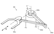
図1は、本実施形態にかかる基板搬送装置としての真空搬送装置を備えるウェハ処理システムの構成の概略を示す平面図である。図2は、搬送アームの構成の概略を示す斜視図である。図3は、後述の真空処理室内の構成の一部のみを概略的に示す図である。
<Wafer Processing System>
Fig. 1 is a plan view showing an outline of the configuration of a wafer processing system including a vacuum transfer device as a substrate transfer device according to the present embodiment. Fig. 2 is a perspective view showing an outline of the configuration of a transfer arm. Fig. 3 is a schematic view showing only a part of the configuration inside a vacuum processing chamber described later.
図1のウェハ処理システム1は、基板としてのウェハWに対して、例えば成膜処理、拡散処理、エッチング処理等の所定の処理を減圧下で行うものである。
このウェハ処理システム1は、複数のウェハWや後述のセンサ付きウェハを収容可能なキャリアCが搬入出されるキャリアステーション10と、減圧下でウェハWに所定の処理を施す複数の各種処理装置を備えた処理ステーション11とを一体に接続した構成を有している。キャリアステーション10と処理ステーション11は、2つのロードロック装置12、13を介して連結されている。
The
This
ロードロック装置12、13は、室内を大気圧状態と真空状態とに切り替えられるように構成されたロードロック室12a、13aを有する。ロードロック装置12、13は、後述する大気圧搬送装置21と真空搬送装置30を連結するように設けられている。
The
キャリアステーション10は、キャリア載置台20と、キャリア載置台20に隣接して設けられた大気圧搬送装置21とを有している。
The
キャリア載置台20には、キャリアCを複数、例えば3つ並べて載置できるように構成されている。
大気圧搬送装置21は、室内が大気圧下とされる大気搬送室22を有する。大気搬送室22は、ロードロック装置12、13のロードロック室12a、13aとゲートバルブG1、G2を介して接続されている。大気搬送室22内にはウェハ搬送機構23が設けられている。ウェハ搬送機構23は、大気圧下において、キャリア載置台20上のキャリアCとロードロック室12a、13aとの間でウェハWを搬送できるように構成されている。
The carrier mounting table 20 is configured so that a plurality of carriers C, for example, three carriers C, can be mounted side by side.
The atmospheric
キャリアステーション10には、大気圧搬送装置21に隣接して設けられたアライナ24をさらに有する。アライナ24は、ウェハWのノッチ等を認識してウェハWの向きの調整を行う。
The
処理ステーション11は、基板搬送装置としての真空搬送装置30と処理装置40~43を有している。
The
真空搬送装置30は、室内が減圧状態(真空状態)に保たれる真空搬送室31を有する。真空搬送室31は、密閉可能に構成された筐体からなり、例えば平面視において略多角形状(図示の例では六角形状)をなすように形成されている。真空搬送室31は、ロードロック装置12、13のロードロック室12a、13aとゲートバルブG3、G4を介して接続されている。また、真空搬送室31は、後述の真空処理室44~47それぞれとゲートバルブG5~G8を介して接続されている。真空搬送室31内には、処理装置40~43の後述の真空処理室44~47との間でウェハWを搬送する、基板搬送機構としてのウェハ搬送機構32が設けられている。
The
ウェハ搬送機構32は、搬送アーム32aと基台32bとを有している。なお、ウェハ搬送機構32に設けられる搬送アームは、複数であってもよい。搬送アーム32aは多関節アームから構成される。基台32bは、搬送アーム32aの根元部分を軸支する。そして、ウェハ搬送機構32は、搬送アーム32aによってウェハWを保持しながら搬送する構成となっている。
The
搬送アーム32aは、図2に示すように、その先端に搬送ピック32cが設けられている。また、基台32bには、搬送ピック32cを移動させるための駆動力を発生する駆動機構32dが設けられている。駆動機構32dはモータ等のアクチュエータを有する。駆動機構32dが発生する駆動力により、搬送アーム32aを基台32bの中心軸Aを回転させ、当該中心軸Aを中心とした周方向(図のθ方向)に搬送ピック32cを移動させることができる。また、駆動機構32dが発生する駆動力により、搬送アーム32aを伸縮させ、基台32bの中心軸Aを中心とした径方向(図のR方向)に搬送ピック32cを移動させることができる。
As shown in FIG. 2, the
また、図1に示すように、真空搬送室31内には、ウェハ搬送機構32の搬送アーム32aの搬送ピック32cに保持されたウェハWの位置を検出するための位置検出機構33が設けられている。位置検出機構33での検出結果に基づいて、後述の制御部51により、搬送ピック32c上におけるウェハWの(基準位置からの)位置ずれが算出される。
As shown in FIG. 1, a
位置検出機構33は、例えば処理装置40~43それぞれに対して設けられている。具体的には、位置検出機構33は、例えば、ゲートバルブG5近傍における処理装置40へのウェハWの搬送経路上、ゲートバルブG6近傍における処理装置41へのウェハWの搬送経路上、ゲートバルブG7近傍における処理装置42へのウェハWの搬送経路上、ゲートバルブG8近傍における処理装置40へのウェハWの搬送経路上に設けられている。
The
各位置検出機構33は、例えば対応するゲートバルブ(ゲートバルブG5~G8のいずれか)に沿って並ぶ一対の光電センサ33a、33bを有する。光電センサ33a、33bは、例えば透過型であり、真空搬送室31内における天井側と床側とにそれぞれ設けられる発光部(図示せず)と受光部(図示せず)とを有し、発光部からの光を受光部が受光するように構成されている。この発光部と受光部との間をウェハWが通過していく間は、受光部による受光が停止し、発光部と受光部との間をウェハWが通り過ぎると、受光部による受光が再開する。光電センサ33a、33bにおける受光停止期間の長さは、搬送ピック32c上におけるウェハWの位置によって異なってくる。そこで、後述の制御部51は、光電センサ33a、33bにおける受光停止期間の長さに基づき、搬送ピック32c上におけるウェハWの(基準位置からの)位置ずれを算出する。なお、搬送ピック32c上におけるウェハWの(基準位置からの)位置ずれの算出方法は、上記の方法に限られず、その他の公知の方法を用いることができる。
Each
処理装置40~43は、ウェハWに対して、例えば成膜処理、拡散処理、エッチング処理等の所定の処理を減圧下で行う。また、処理装置40~43はそれぞれ、減圧下の室内でウェハWに対して上記所定の処理が行われる真空処理室44~47を有する。
なお、処理装置40~43には、ウェハ処理の目的に応じた処理を行う装置を、任意に選択することができる。
The
It should be noted that the
処理装置40の真空処理室44内には、図3に示すように、載置台100が設けられている。載置台100の中央部の上面は、ウェハが載置される載置面100aを構成する。また、載置台100の周縁部の上面は、中央部の上面より高く形成されている。つまり、載置台100は、載置面100aの周縁を囲み且つ上方に突出するように設けられた、載置面100aと同心となる環状の段差部Dを有する。段差部Dの高さは例えば1~3mmである。
なお、載置台100における、載置面100aを構成する部材と、段差部Dを構成する部材とを別部材としてもよい。
As shown in FIG. 3, a mounting table 100 is provided in the
In addition, in the mounting table 100, the member constituting the mounting
また、真空処理室44内における載置台100の下方には、複数、例えば3本の支持ピン110が上下方向に延びるように設けられている。これら支持ピン110は、当該支持ピン110を上下動させる昇降機構120に接続されている。昇降機構120は、例えば、複数の支持ピン110を支持する支持部材121と、支持部材121を昇降させる駆動力を発生させ、複数の支持ピン110を上下動させる駆動部122とを有する。駆動部122は、上記駆動力を発生するモータ等のアクチュエータ(図示せず)を有する。支持ピン110は、上下動することにより、載置台100と搬送ピック32cとの間でのウェハWの受け渡しのために、載置台100に形成された貫通孔100bを介して、当該載置台100の載置面100aから突没する。
In addition, below the mounting table 100 in the
真空処理室45~47内にも、真空処理室44と同様に、載置台100や支持ピン110等が設けられている。
Similar to vacuum processing
さらに、図1に示すように、ウェハ処理システム1には、制御装置50が設けられている。制御装置50は、制御部51と、通信部52と、記憶部53と、を有する。
Furthermore, as shown in FIG. 1, the
制御部51は、ウェハ処理システム1におけるウェハ処理を制御する制御信号を出力したり、真空搬送装置30から処理装置40~43それぞれへのウェハWの受け渡し位置を補正したりするものであり、例えば、CPU等のプロセッサと、RAMやROM等の記憶手段と、を含んで成る。
The
通信部52は、後述のセンサ付きウェハとの間で通信を行う。通信部52は、例えば、センサ付きウェハに設けられた傾きセンサによる検出結果をセンサ付きウェハから受信する。通信部52とセンサ付きウェハとの間の通信形態は例えば無線である。
The
記憶部53は、各種情報を記憶するものであり、HDD(Hard Disk Drive)やRAM、ROM等から成る。記憶部53には、ウェハ搬送機構32の駆動機構32dや昇降機構120の駆動部122等を制御してウェハ処理システム1におけるウェハ処理を制御するプログラムが格納されている。また、記憶部53には、真空搬送装置30から処理装置40~43それぞれへのウェハWの受け渡し位置を補正するためのプログラムが格納されている。これらのプログラムは、コンピュータに読み取り可能な記憶媒体に記録されていたものであって、当該記憶媒体から制御装置50にインストールされたものであってもよい。
The
<ウェハ処理>
次に、以上のように構成されたウェハ処理システム1を用いて行われるウェハ処理の一例について説明する。なお、以下の処理は、制御部51による制御の下、行われる。
<Wafer Processing>
Next, a description will be given of an example of wafer processing performed using the
(A1:ウェハWの真空搬送装置30への搬入)
まず、ウェハWが真空搬送装置30へ搬入される。具体的には、まず、例えば、ウェハ搬送機構23の搬送アーム23aによって、ウェハWが、キャリアCから取り出され、アライナ24に搬入される。続いて、アライナ24においてウェハWの向きの調整が行われる。次いで、ウェハWが、搬送アーム23aによって、アライナ24から取り出されると共に、ゲートバルブG1が開状態とされる。その後、ウェハWが、搬送アーム23aによって、ロードロック装置12に搬入され、ロードロック装置12内の支持部(図示せず)に、受け渡される。
(A1: Loading the wafer W into the vacuum transfer device 30)
First, the wafer W is carried into the
続いて、搬送アーム23aがロードロック装置12から抜き出され、また、ゲートバルブG1が閉状態とされてロードロック装置12内が密閉され、減圧される。
Next, the
ロードロック装置12内の圧力が所定の圧力以下となると、ゲートバルブG3が開状態とされ、搬送アーム32aの搬送ピック32cによって、ウェハWが、ロードロック装置12内の支持部(図示せず)から受け取られ、ロードロック装置12から取り出される。その後、ゲートバルブG3が閉状態とされる。
When the pressure inside the
(A2:載置台100への受け渡し)
次に、ウェハWが例えば処理装置40の載置台100へ受け渡される。具体的には、例えば、ゲートバルブG5が開状態とされ、その後、処理装置40にかかる受け渡し位置に、真空搬送装置30の搬送ピック32cが移動されて、ウェハWが処理装置40の真空処理室44内に搬入される。より具体的には、搬送ピック32cの移動の際に、処理装置40に対応する位置検出機構33をウェハWが通過するため、制御部51が、位置検出機構33での検出結果に基づいて、搬送ピック32c上におけるウェハWの(基準位置からの)位置ずれを算出する。そして、制御部51が、上記位置ずれに基づいて、処理装置40にかかる受け渡し位置を修正する。このように上記位置ずれに基づいて修正された受け渡し位置に搬送ピック32cが移動されて、ウェハWが処理装置40の真空処理室44内に搬入される。
搬入後、処理装置40の支持ピン110の上昇が行われ支持ピン110にウェハWが受け渡され、搬送ピック32cの真空処理室44内からの抜き出し及び支持ピン110の下降が行われ、ウェハWが、処理装置40の真空処理室44内で、載置台100に受け渡され載置される。
(A2: Delivery to the mounting table 100)
Next, the wafer W is transferred to, for example, the mounting table 100 of the
After the wafer W is loaded, the support pins 110 of the
(A3:処理)
続いて、ゲートバルブG5が閉状態とされて、処理装置40の真空処理室44が密閉され、その後、処理装置40において、ウェハWに対し、エッチング処理等の処理が行われる。
(A3: Processing)
Next, the gate valve G5 is closed to hermetically seal the
(A4:載置台100からの受け取り)
その後、上記工程A2と逆の手順で、ウェハWが、真空搬送装置30により処理装置40の載置台100から受け取られる。ただし、位置検出機構33での検出は省略される。
(A4: Receiving from the mounting table 100)
Thereafter, the wafer W is received from the mounting table 100 of the
(A5:ウェハWの真空搬送装置30からの搬出)
その後、上記工程A1と逆の手順で、ウェハWが、真空搬送装置30から搬出され、キャリアCに戻される。ただし、キャリアCに戻される過程において、アライナ24へのウェハWの搬入出及びアライナ24におけるウェハWの向きの調整は省略される。
これにより一連のウェハ処理が終了する。
(A5: Removal of wafer W from vacuum transfer device 30)
Thereafter, in a procedure reverse to that of step A1, the wafer W is unloaded from the
This completes the series of wafer processing steps.
なお、処理装置40にかかる受け渡し位置が後述の補正方法で補正された後は、上記工程A2、A4では上記受け渡し位置として補正後の受け渡し位置が用いられる。
After the transfer position of the
<補正方法>
次に、真空搬送装置30から各処理装置40~43へのウェハWの受け渡し位置の補正方法について図4~図7を用いて説明する。以下では、処理装置40への受け渡し位置の補正方法について説明するが、処理装置41~43それぞれへの受け渡し位置も同様な方法で補正することができる。図4は、後述のセンサ付きウェハを説明するための側面図である。図5は、センサ付きウェハを載置台100に受け渡した際に当該ウェハの全体が載置面100a上に位置するときの様子を示す図である。図6は、センサ付きウェハを載置台100に受け渡した際に当該ウェハの一部が載置台100の段差部に乗り上げるときの様子を示す図である。なお、図5及び図6では、後述のセンサユニットの図示を省略している。また、図7は、受け渡し位置と当該位置から載置台に受け渡されたセンサ付きウェハの傾きの関係を示す図である。
<Correction method>
Next, a method for correcting the transfer position of the wafer W from the
本実施形態にかかる処理装置40への受け渡し位置の補正では、センサ付き基板としてのセンサ付きウェハWsが用いられる。
センサ付きウェハWsは、平面視での形状がウェハWと同一であり、ウェハ搬送機構23、32により搬送可能に構成されている。また、センサ付きウェハWsは、上述のように平面視での形状がウェハWと同一であることから、ウェハWと同様に、位置検出機構33での検出結果に基づいて、制御部51により、搬送ピック32c上における位置ずれが算出可能である。このセンサ付きウェハWsは、図4に示すように、ウェハ本体200と、センサユニット210とを有する。
In the correction of the transfer position to the
The sensor-fitted wafer Ws has the same shape as the wafer W in a plan view, and is configured to be transportable by the
ウェハ本体200は、ウェハWを模した部材であり、具体的には、ウェハWと同径(例えば300mm)の円板状に形成された部材である。また、ウェハ本体200には、ウェハWと同様、例えばノッチ(図示せず)が形成されている。
The
センサユニット210は、センサ付きウェハWsの水平に対する傾きを検出する傾きセンサ211と、ウェハ処理システム1の制御装置50の通信部52と通信する通信手段(図示せず)とを有する。通信手段は、傾きセンサ211による検出結果等を制御装置50の通信部52に送信し、通信部52からの制御部51による制御信号を受信する。
また、センサユニット210は、電源(図示せず)や制御部(図示せず)を有する。センサユニット210の制御部は、プロセッサ及び記憶手段を有し、記憶手段に記憶されたプログラムを実行して、傾きセンサ211による検出結果が制御装置50の通信部52に送信されるよう制御する。
The
The
以上のように構成されたセンサ付きウェハWsを用いた処理装置40にかかる受け渡し位置の補正方法では、まず、制御部51の制御の下、センサ付きウェハWsを保持した搬送ピック32cを、処理装置40にかかる仮の受け渡し位置に移動させ、センサ付きウェハWsを搬送ピック32cから載置台100に受け渡し載置させる(載置工程)。
続いて、仮の受け渡し位置の搬送ピック32cから載置台100に載置されたセンサ付きウェハWsの傾きが、傾きセンサ211により検出される(傾き検出工程)。
In the method for correcting the transfer position in the
Next, the inclination of the sensor-equipped wafer Ws placed on the placement table 100 from the
また、本実施形態にかかる受け渡し位置の補正方法では、上述の載置工程及び傾き検出工程が、互いに異なる複数の仮の受け渡し位置について行われる。
さらに、本実施形態にかかる受け渡し位置の補正方法では、上記互いに異なる複数の仮の受け渡し位置には、以下の(a)、(b)が含まれるようにする。
(a)当該位置の搬送ピック32cからセンサ付きウェハWsを載置台100に受け渡して載置したときに、図5に示すように当該ウェハWsの全体が載置面100a上に位置し当該ウェハWsが傾かない位置
(b)当該位置の搬送ピック32cからセンサ付きウェハWsを載置台100に受け渡して載置したときに、図6に示すように当該ウェハWsの一部が段差部Dに乗り上げ当該ウェハWsが大きく傾く位置
In the method for correcting the transfer position according to this embodiment, the above-mentioned placing step and tilt detection step are performed for a plurality of temporary transfer positions that are different from one another.
Furthermore, in the method for correcting the transfer position according to this embodiment, the plurality of mutually different provisional transfer positions include the following (a) and (b).
(a) When the sensor-equipped wafer Ws is transferred from the
これにより、図7に示すように、仮の受け渡し位置(の座標)と、当該位置の搬送ピック32cから載置台100に載置されたセンサ付きウェハWsの傾きとの関係が得られる。
As a result, as shown in FIG. 7, the relationship between the (coordinates of) the temporary transfer position and the inclination of the sensor-equipped wafer Ws placed on the mounting table 100 from the
本実施形態にかかる受け渡し位置の補正方法では、制御部51が、複数の仮の受け渡し位置についての上記傾き検出工程での検出結果に基づいて、処理装置40にかかる受け渡し位置を補正する。具体的には、制御部51は、例えば、複数の仮の受け渡し位置についての上記傾き検出工程での検出結果から、センサ付きウェハWsの傾きの大きさが閾値以下となる仮の受け渡し位置の範囲(図7の符号R参照)を特定し、当該範囲の中心を、処理装置40にかかる補正後の受け渡し位置に決定する。
In the transfer position correction method according to the present embodiment, the
<補正方法のより具体的な例>
続いて、処理装置40にかかる受け渡し位置の補正方法のより具体的な例について説明する。処理装置40にかかる受け渡し位置の補正は、例えば処理装置40の真空処理室44内の部品が交換された際や、ウェハWの搬送にトラブルが生じた時、処理装置40のメンテナンス時等に行われる。
<More specific example of correction method>
Next, a more specific example of a method for correcting the transfer position in the
(B1:センサ付きウェハWsの真空搬送装置30への搬入)
まず、制御部51の制御の下、センサ付きウェハWsが真空搬送装置30へ搬入される。
具体的には、まず、例えば、センサ付きウェハWsが収納された、キャリア載置台20上のキャリアCから、ウェハ搬送機構23の搬送アーム23aによって、センサ付きウェハWsが取り出され、アライナ24に搬入される。
(B1: Loading the sensor-equipped wafer Ws into the vacuum transfer device 30)
First, under the control of the
Specifically, first, for example, the sensor-fitted wafer Ws is removed from the carrier C on the carrier mounting table 20 in which the sensor-fitted wafer Ws is stored, and is carried into the
続いて、アライナ24においてセンサ付きウェハWsの向きの調整が行われる。具体的には、センサ付きウェハWsの傾きセンサ211が一の軸周りの傾きと上記一の軸と直交する他の軸周りの傾きを検出可能な場合、処理装置40にかかる受け渡し位置の座標系におけるX軸及びY軸が上記一の軸及び上記他の軸と一致するようにウェハWの向きの調整が行われる。この調整はセンサ付きウェハWsのウェハ本体200に設けられたノッチ(図示せず)の検出結果に基づいて行われる。
Then, the orientation of the sensor-equipped wafer Ws is adjusted in the
次いで、センサ付きウェハWsが、搬送アーム23aによって、アライナ24から取り出されると共に、ゲートバルブG1が開状態とされる。その後、センサ付きウェハWsが、搬送アーム23aによって、ロードロック装置12に搬入され、ロードロック装置12内の支持部(図示せず)に、受け渡される。
Next, the sensor-equipped wafer Ws is removed from the
続いて、搬送アーム23aがロードロック装置12から抜き出され、また、ゲートバルブG1が閉状態とされてロードロック装置12内が密閉され、減圧される。
Next, the
ロードロック装置12内の圧力が所定の圧力以下となると、ゲートバルブG3が開状態とされ、搬送アーム32aの搬送ピック32cによって、センサ付きウェハWsが、ロードロック装置12内の支持部(図示せず)から受け取られ、ロードロック装置12から取り出される。その後、ゲートバルブG3が閉状態とされる。
When the pressure inside the
(B2:載置台100への受け渡し)
次に、制御部51の制御の下、センサ付きウェハWsが処理装置40の載置台100へ受け渡される。具体的には、例えば、ゲートバルブG5が開状態とされ、その後、処理装置40にかかる仮の受け渡し位置に、真空搬送装置30の搬送ピック32cが移動されて、センサ付きウェハWsが処理装置40の真空処理室44内に搬入される。より具体的には、搬送ピック32cの移動の際に、処理装置40に対応する位置検出機構33をセンサ付きウェハWsが通過するため、制御部51が、位置検出機構33での検出結果に基づいて、搬送ピック32c上におけるセンサ付きウェハWsの(基準位置からの)位置ずれを算出する。そして、制御部51が、上記位置ずれに基づいて、処理装置40にかかる仮の受け渡し位置を修正する。このように上記位置ずれに基づいて修正された仮の受け渡し位置に搬送ピック32cが移動されて、ウェハWが処理装置40の真空処理室44内に搬入される。
搬入後、処理装置40の支持ピン110の上昇が行われ支持ピン110にセンサ付きウェハWsが受け渡される。次いで、搬送ピック32cの真空処理室44内からの抜き出し及び支持ピン110の下降が行われ、センサ付きウェハWsが、処理装置40の真空処理室44内で、載置台100に受け渡され載置される。
(B2: Delivery to the mounting table 100)
Next, under the control of the
After the loading, the support pins 110 of the
(B3:傾き検出)
続いて、制御部51の制御の下、仮の受け渡し位置の搬送ピック32cから載置台100に受け渡されたセンサ付きウェハWsの傾きが、傾きセンサ211により検出される。具体的には、制御部51が、センサ付きウェハWsのセンサユニット210の制御部に、傾きを測定するよう指令を送信する。上記指令を受けたセンサユニット210の制御部が、傾きセンサ211の検出結果を取得し、制御部51に送信する。制御部51は、通信部52を介して上記傾きセンサ211の検出結果を受信し、記憶部53に記憶させる。
(B3: Tilt detection)
Next, under the control of the
(B4:載置台100からの受け取り及び処理装置40からの抜き出し)
次に、制御部51の制御の下、処理装置40の載置台100上のセンサ付きウェハWsが搬送ピック32cに受け取られ、処理装置40から抜き出される。
具体的には、例えば、まず、処理装置40の支持ピン110の上昇が行われ支持ピン110にセンサ付きウェハWsが受け渡される。その後、搬送ピック32cが、例えば、前述の修正された仮の受け渡し位置に移動されると共に、支持ピン110の下降が行われ、センサ付きウェハWsが搬送ピック32cに受け渡される。次いで、搬送ピック32cの真空処理室44内からの抜き出し及び支持ピン110の下降が行われる。
(B4: Receiving from the mounting table 100 and removing from the processing device 40)
Next, under the control of the
Specifically, for example, first, the support pins 110 of the
本実施形態にかかる補正方法では、上述の工程B2~B4が、受け渡し位置の座標系におけるX軸方向に関し、互いに異なる複数の仮の受け渡し位置それぞれについて行われる。
例えば、まず、現在設定されている受け渡し位置を仮の受け渡し位置の初期位置として、上述の工程B2~B4が行われる。
In the correction method according to the present embodiment, the above-mentioned steps B2 to B4 are performed for each of a plurality of provisional transfer positions that are different from one another in relation to the X-axis direction in the coordinate system of the transfer position.
For example, first, the currently set transfer position is set as a tentative initial transfer position, and the above-mentioned steps B2 to B4 are carried out.
その結果、工程B3で検出された、Y軸周りの傾きの大きさが閾値を超える場合(すなわち図6の場合)、制御部51は、上記傾きが正の値のときは上記傾きが小さくなるよう、仮の受け渡し位置のX座標を上記初期位置から段階的に(例えば0.1mmずつや0.25mmずつ)小さくさせてゆく。また、制御部51は、上記傾きが負の値のときは上記傾きが大きくなるよう、仮の受け渡し位置のX座標を上記初期位置から段階的に(例えば0.1mmずつや0.25mmずつ)大きくさせてゆく。
上述のように仮の受け渡し位置を段階的に変更すると共に、制御部51は、各仮の受け渡し位置について工程B2~B4が実行されるよう制御を行う。
また、上述の仮の受け渡し位置の段階的な変更、及び、各仮の受け渡し位置での工程B2~B4の実行は、Y軸周りの傾きの大きさが閾値以下となった後に再び閾値を超えるまで行われる。
As a result, when the magnitude of the tilt about the Y axis detected in step B3 exceeds the threshold value (i.e., in the case of FIG. 6), the
As described above, the temporary transfer positions are changed stepwise, and the
Furthermore, the above-mentioned stepwise change of the provisional transfer position and the execution of steps B2 to B4 at each provisional transfer position are performed until the magnitude of the inclination around the Y axis becomes equal to or smaller than the threshold and then exceeds the threshold again.
一方、仮の受け渡し位置の初期位置について工程B2~B4を行った結果、工程B3で検出された、Y軸周りの傾きの大きさが閾値以下の場合(すなわち図5の場合)、制御部51は、上記傾きが大きくなるよう、仮の受け渡し位置のX座標を上記初期位置から段階的に(例えば0.1mmずつや0.25mmずつ)大きくさせてゆく。それと共に、制御部51は、各仮の受け渡し位置について工程B2~B4が実行されるよう制御を行う。
この仮の受け渡しの段階的な変更、及び、各仮の受け渡し位置での工程B2~B4の実行は、Y軸周りの傾きの大きさが閾値を超えるまで行われる。
その後、制御部51は、上記傾きが小さくなるよう、仮の受け渡し位置のX座標を上記初期位置から段階的に(例えば0.1mmずつや0.25mmずつ)小さくさせてゆく。それと共に、制御部51は、各仮の受け渡し位置について工程B2~B4が実行されるよう制御を行う。
この仮の受け渡しの段階的な変更、及び、各仮の受け渡し位置での工程B2~B4の実行は、Y軸周りの傾きの大きさが閾値を超えるまで行われる。
On the other hand, when the magnitude of the tilt about the Y axis detected in step B3 is equal to or smaller than the threshold value as a result of performing steps B2 to B4 for the initial position of the temporary transfer position (i.e., the case of FIG. 5), the
This gradual change of the temporary transfer position and the execution of steps B2 to B4 at each temporary transfer position are performed until the magnitude of the tilt around the Y axis exceeds a threshold value.
Thereafter, the
This gradual change of the temporary transfer position and the execution of steps B2 to B4 at each temporary transfer position are performed until the magnitude of the tilt around the Y axis exceeds a threshold value.
本実施形態にかかる補正方法では、受け渡し位置の座標系におけるY軸方向に関しても、X軸方向と同様に、互いに異なる複数の仮の受け渡し位置それぞれについて、工程B2~B4が行われる。 In the correction method according to this embodiment, steps B2 to B4 are performed for each of a plurality of mutually different provisional transfer positions in the Y-axis direction in the coordinate system of the transfer position, just as in the X-axis direction.
なお、上述のように仮の受け渡し位置を段階的に変更する際、制御部51が、一旦、大きな幅(例えば0.5mmずつ)で段階的に変更すると共に各仮の受け渡し位置で工程B2~B4を実行させ、センサ付きウェハWsの傾きの大きさが閾値以下となる位置と閾値を超える位置との境界となりうる範囲を取得してもよい。そして、制御部51が、上記境界となりうる範囲で、小さな幅で仮の受け渡し位置を段階的に変更すると共に、各仮の受け渡し位置で工程B2~B4を実行させるようにしてもよい。これにより、センサ付きウェハWsの傾きの大きさが閾値以下となる仮の受け渡し位置と、同大きさが閾値を超える仮の受け渡し位置との境界を高速且つ正確に特定することができる。
When changing the provisional transfer position in stages as described above, the
(B5:受け渡し位置の補正)
工程B2~B4が上述のようにX軸方向及びY軸方向の両方に関して複数の仮の受け渡し位置について行われた後、制御部51は、各仮の受け渡し位置についての工程B3での検出結果から、処理装置40にかかる受け渡し位置を補正する。具体的には、制御部51は、上記検出結果から、センサ付きウェハWsの傾きの大きさが閾値以下となる、仮の受け渡し位置のX座標及びY座標の範囲を特定する。そして、制御部51は、当該範囲の中心を、処理装置40にかかる補正後の受け渡し位置に決定する。例えば、仮の受け渡し位置のX座標がx1~x2の範囲でY軸周りの角度の大きさが閾値以下となり、仮の受け渡し位置のY座標がy1~y2の範囲でX軸周りの角度の大きさが閾値以下となる場合、制御部51は、((x1+x2)/2、(y1+y2)/2)で示される位置を補正後の受け渡し位置に決定し、記憶部53に記憶させる。
(B5: Correction of delivery position)
After steps B2 to B4 are performed for a plurality of temporary transfer positions in both the X-axis direction and the Y-axis direction as described above, the
(B6:センサ付きウェハWsの真空搬送装置30からの搬出)
その後、工程B1と逆の手順で、センサ付きウェハWsが、真空搬送装置30から搬出され、キャリアCに戻される。ただし、キャリアCに戻される過程において、アライナ24へのセンサ付きウェハWsの搬入出及びアライナ24におけるセンサ付きウェハWsの向きの調整は省略される。
(B6: Removal of the sensor-fitted wafer Ws from the vacuum transfer device 30)
Thereafter, in a procedure reverse to that of step B1, the sensor-equipped wafer Ws is unloaded from the
なお、工程B2~B4を複数の仮の受け渡し位置について行った後に工程B5を行う一連の工程を、二回繰り返し、一回目に決定された補正後の受け渡し位置と二回目に決定された補正後の受け渡し位置との間のずれ量が許容値を超えるか否か判定するようにしてもよい。
判定の結果、許容値以下の場合、制御部51は、例えば、一回目の補正後の受け渡し位置又は二回目の補正後の受け渡し位置を、補正後の受け渡し位置に決定する。
また、判定の結果、許容値を超える場合、制御部51は、上記一連の工程を再度実行させるようにしてもよい。そして、連続する2回の上記一連の工程間で、補正後の受け渡し位値の値が許容値以下となるまで、上記一連の工程が繰り返し実行されるようにしてもよい。
In addition, the series of steps of performing steps B2 to B4 for a plurality of temporary transfer positions and then performing step B5 may be repeated twice, and it may be determined whether the amount of deviation between the corrected transfer position determined in the first step and the corrected transfer position determined in the second step exceeds an allowable value.
If the result of the determination is that the difference is equal to or less than the allowable value, the
Furthermore, if the result of the determination is that the tolerance is exceeded, the
以上のように、本実施形態にかかる、処理装置40への受け渡し位置の補正方法は、センサ付きウェハWsを、搬送ピック32cで保持して仮の受け渡し位置に移動させ、搬送ピック32cから載置台100に受け渡し載置する載置工程を有する。また、本補正方法は、載置台100に受け渡されたセンサ付きウェハWsの傾きを傾きセンサ211で検出する傾き検出工程を有する。さらに、本補正方法は、上記載置工程と上記傾き検出工程を、互いに異なる複数の仮の受け渡し位置について行う。また、上記複数の仮の受け渡し位置には、当該位置の搬送ピック32cからセンサ付きウェハWsを載置台100に受け渡したときに当該ウェハWsの一部が段差部Dに乗り上げる位置が含まれる。そして、本補正方法は、さらに、傾き検出工程での検出結果に基づいて、受け渡し位置を補正する工程を有する。
As described above, the method for correcting the transfer position to the
本補正方法は、補正に際し、処理装置40の真空処理室44を大気開放する必要がない。そのため、受け渡し位置を短時間で補正することができる。
また、本補正方法は、段差部Dの高さによらず、適用することができる。特に、エッチング処理等の処理を重ねた結果、段差部Dの高さが変化する場合があり、本補正方法は、このように高さが変化した前と後との両方に適用することができる。
さらに、本補正方法は、作業者の手によらず、自動的に受け渡し位置を補正することができる。本方法と異なり、作業者による作業を伴う補正方法では、作業者の熟練度によって、適切な補正後の受け渡し位置が得られない場合があるが、本補正方法ではそのような問題は生じない。
In this correction method, there is no need to open the
Furthermore, this correction method can be applied regardless of the height of the step portion D. In particular, the height of the step portion D may change as a result of repeated etching processes or other processes, and this correction method can be applied both before and after such a change in height occurs.
Furthermore, this correction method can automatically correct the transfer position without the manual intervention of an operator. Unlike this method, correction methods that require manual work may not be able to obtain an appropriate corrected transfer position depending on the operator's level of skill, but this correction method does not have such a problem.
また、本補正方法では、前述の工程B2のように、仮の受け渡しの位置にセンサ付きウェハWsを保持した搬送ピック32cを移動させる際、当該搬送ピック32c上における上記ウェハWsの位置ずれの検出が行われる。そして、前述の工程B2では、この検出結果に基づいて修正された仮の受け渡し位置に搬送ピック32cが移動され、この搬送ピック32cから載置台100にセンサ付きウェハWsが受け渡される。したがって、搬送ピック32c上におけるセンサ付きウェハWsの位置ずれによらず、搬送ピック32cから載置台100への受け渡し時のセンサ付きウェハWsの位置を所望の位置とすることができる。
ところで、前述の工程B2でセンサ付きウェハWsの一部が段差部Dに乗り上げるように当該ウェハWsが載置台100に載置された場合において、前述の工程B4で支持ピン110を介して上記ウェハWsを搬送ピック32cで受け取ったときに、搬送ピック32cに対して上記ウェハWsがずれることがある。このようにずれたとしても、次の仮の受け渡し位置に搬送ピック32cを動かすときに、上述のように搬送ピック32c上における上記ウェハWsの位置ずれの検出結果に基づいて仮の受け渡し位置を修正すれば、次の仮の受け渡し位置の搬送ピック32cから載置台100へ受け渡す時に、センサ付きウェハWsの位置を所望の位置とすることができる。
In addition, in this correction method, when the
Incidentally, in the above-mentioned step B2, when the sensor-fitted wafer Ws is placed on the mounting table 100 so that a part of the wafer Ws rides on the step portion D, the wafer Ws may be misaligned with respect to the
<補正方法の他の例>
以上の例では、載置工程及び傾き検出工程を互いに異なる複数の仮の受け渡し位置について行ったが、段差部Dの高さが予め記憶部53に記憶されている等して取得可能なときは、載置工程及び傾き検出工程を一の仮の受け渡し位置についてのみ行うようにしてもよい。この場合、上記一の仮の受け渡し位置としては、当該位置の搬送ピック32cからセンサ付きウェハWsを載置台100に受け渡したときに当該ウェハWsの一部が段差部Dに乗り上げる位置が選択される。そして、この一の仮の受け渡し位置についての、上記傾き検出工程での検出結果に基づいて、制御部51が受け渡し位置を補正する。具体的には、制御部51が、段差部Dの高さと、段差部Dに一部が乗り上げたセンサ付きウェハWsの傾きとから、当該センサ付きウェハWsの中心の、載置面100aの中心からのずれ(以下、「中心ずれ」という。)を推定する。この推定された中心ずれと、仮の受け渡し位置とに基づいて、制御部51は、補正後の受け渡し位置を決定する。より具体的には、制御部51は、載置工程及び傾き検出工程を一の仮の受け渡しについてのみ行い、且つ、傾き検出工程での検出工程に基づいて上記中心ずれを推定し補正後の受け渡し位置を決定することを、受け渡し位置の座標系におけるX軸方向及びY軸方向それぞれに関して行う。例えば、推定されたX軸方向及びY軸方向にかかる上記中心ずれがそれぞれΔx及びΔyであり、仮の受け渡し位置の座標が(xv、yv)である場合、制御部51は、補正後の受け渡し位置の座標を(xv-Δx、yv-Δy)とする。
<Other examples of correction methods>
In the above example, the placing step and the tilt detection step are performed for a plurality of different temporary transfer positions. However, when the height of the step portion D is previously stored in the
この補正方法の場合も、載置工程及び傾き検出工程を一の仮の受け渡し位置について行った後に補正する工程を行う一連の工程を、二回繰り返し、一回目の補正後の受け渡し位置と二回目の補正後の受け渡しとの間のずれ量が許容値を超える場合、上記一連の工程を再度行うようにしてもよい。 In the case of this correction method, the series of steps of performing the placement process and the tilt detection process for one temporary transfer position, followed by the correction process, may be repeated twice, and if the deviation between the transfer position after the first correction and the transfer position after the second correction exceeds the allowable value, the series of steps described above may be performed again.
<変形例>
補正する工程で決定された補正後の受け渡し位置を記憶部53に蓄積するようにしてもよい。これにより、例えば、処理装置40によるエッチング処理等の処理の結果に異状があったときに、受け渡し位置の補正すなわちティーチングが適切に行われていたか否かを、蓄積された補正後の受け渡し位置の情報から判断することができる。
<Modification>
The corrected transfer position determined in the correction step may be stored in the
以上の例では、センサ付きウェハWsが、キャリア載置台20に載置されたキャリアCから真空搬送装置30に搬入されるものとした。これに代えて、センサ付きウェハWsを、ロードロック装置12、13の天蓋を開けて、支持部(図示せず)上にセンサ付きウェハWsを載置し、ここから真空搬送装置30に搬入されるようにしてもよい。
また、以上の例では、センサ付きウェハWsがキャリアCに収納されていた。これに代えて収納モジュールを真空搬送装置30や大気圧搬送装置21に設け、この収納モジュールにセンサ付きウェハWsを収納するようにしてもよい。
In the above example, the sensor-fitted wafer Ws is transferred from the carrier C placed on the carrier mounting table 20 into the
In the above example, the sensor-fitted wafer Ws is stored in the carrier C. Instead of this, a storage module may be provided in the
今回開示された実施形態はすべての点で例示であって制限的なものではないと考えられるべきである。上記の実施形態は、添付の請求の範囲及びその主旨を逸脱することなく、様々な形態で省略、置換、変更されてもよい。 The embodiments disclosed herein should be considered in all respects as illustrative and not restrictive. The above-described embodiments may be omitted, substituted, or modified in various ways without departing from the scope and spirit of the appended claims.
30 真空搬送装置
32c 搬送ピック
32d 駆動機構
40 処理装置
41 処理装置
42 処理装置
43 処理装置
51 制御部
100 載置台
100a 載置面
D 段差部
W ウェハ
Ws センサ付きウェハ
30
Claims (6)
前記基板搬送装置は、基板を保持する保持部を有し、
前記処理装置は、前記基板が載置される載置面と、当該載置面の周縁を囲み且つ上方に突出するように設けられた、当該載置面と同心となる環状の段差部と、を有する載置台を備え、
前記基板を模した基板本体に傾きセンサが設けられたセンサ付き基板を、前記保持部で保持して仮の受け渡し位置に移動させ、前記保持部から前記載置台に受け渡し載置する工程と、
前記載置台に受け渡された前記センサ付き基板の傾きを前記傾きセンサで検出する工程と、を、一または互いに異なる複数の前記仮の受け渡し位置について行い、
前記一または互いに異なる複数の前記仮の受け渡し位置は、当該位置から前記センサ付き基板を前記載置台に受け渡したときに前記センサ付き基板の一部が前記段差部に乗り上げる位置を含み、
さらに、前記検出する工程での検出結果に基づいて、前記受け渡し位置を補正する工程を有する、補正方法。 A method for correcting a transfer position of a substrate from a substrate transport device to a processing device that processes the substrate under a reduced pressure atmosphere, comprising the steps of:
The substrate transport device has a holder for holding a substrate,
the processing apparatus includes a mounting table having a mounting surface on which the substrate is placed, and a ring-shaped step portion that is concentric with the mounting surface and that surrounds a periphery of the mounting surface and protrudes upward,
a step of holding a sensor-equipped substrate, which has a tilt sensor provided on a substrate main body simulating the substrate, by the holding unit, moving the substrate to a temporary transfer position, and transferring the substrate from the holding unit to the placement table;
detecting a tilt of the sensor-equipped substrate transferred to the mounting table by the tilt sensor, the step being performed for one or a plurality of different temporary transfer positions;
the one or the plurality of different temporary transfer positions include a position where a part of the sensor-equipped substrate runs onto the step portion when the sensor-equipped substrate is transferred from the position to the mounting table,
The correction method further comprises a step of correcting the transfer position based on a result of the detection in the detection step.
前記載置する工程は、前記位置ずれの検出結果に基づいて修正された前記仮の受け渡し位置に、前記センサ付き基板を前記保持部で保持して移動させ、前記保持部から前記載置台に受け渡し載置する、請求項1~3のいずれか1項に記載の補正方法。 detecting a positional deviation of the sensor-equipped substrate on the holder that holds the sensor-equipped substrate,
The correction method according to any one of claims 1 to 3, wherein the placing step comprises holding and moving the sensor-equipped substrate by the holding part to the temporary transfer position corrected based on the detection result of the positional deviation, and transferring and placing the substrate from the holding part to the placement table.
前記処理装置が、前記基板が載置される載置面と、当該載置面の周縁を囲み且つ上方に突出するように設けられた、当該載置面と同心となる環状の段差部と、を有する載置台を備え、
前記基板搬送装置は、
前記基板を保持する保持部と、
前記保持部を移動させるための駆動機構と、
制御部と、を備え、
前記制御部は、
前記基板を模した基板本体に傾きセンサが設けられたセンサ付き基板を、前記保持部で保持して仮の受け渡し位置に移動させ、前記保持部から前記載置台に受け渡し載置する工程と、
前記載置台に受け渡された前記センサ付き基板の傾きを前記傾きセンサで検出する工程と、が、一または互いに異なる複数の前記仮の受け渡し位置について行われるように制御信号を出力し、
前記一または互いに異なる複数の前記仮の受け渡し位置は、当該位置から前記センサ付き基板を前記載置台に受け渡したときに前記センサ付き基板の一部が前記段差部に乗り上げる位置を含み、
前記制御部は、さらに、前記検出する工程での検出結果に基づいて、前記処理装置への前記基板の受け渡し位置を補正する、基板搬送装置。 A substrate transport device that transports a substrate to a processing device that processes the substrate under a reduced pressure atmosphere,
the processing apparatus includes a mounting table having a mounting surface on which the substrate is placed, and a ring-shaped step portion that is concentric with the mounting surface and that is provided so as to surround a periphery of the mounting surface and protrude upward,
The substrate transport device is
A holder for holding the substrate;
A drive mechanism for moving the holding portion;
A control unit,
The control unit is
a step of holding a sensor-equipped substrate, which has a tilt sensor provided on a substrate main body simulating the substrate, by the holding unit, moving the substrate to a temporary transfer position, and transferring the substrate from the holding unit to the placement table;
a step of detecting a tilt of the sensor-equipped substrate transferred to the mounting table by the tilt sensor; and outputting a control signal so that the step is performed at one or a plurality of different temporary transfer positions;
the one or the plurality of different temporary transfer positions include a position where a part of the sensor-equipped substrate runs onto the step portion when the sensor-equipped substrate is transferred from the position to the mounting table,
The control unit further corrects a transfer position of the substrate to the processing device based on a detection result in the detecting step.
Priority Applications (3)
| Application Number | Priority Date | Filing Date | Title |
|---|---|---|---|
| JP2020200793A JP7474688B2 (en) | 2020-12-03 | 2020-12-03 | Correction method and substrate transport device |
| KR1020210164091A KR102711816B1 (en) | 2020-12-03 | 2021-11-25 | Correction method and substrate transfer apparatus |
| US17/536,467 US12469724B2 (en) | 2020-12-03 | 2021-11-29 | Correction method and substrate transfer apparatus |
Applications Claiming Priority (1)
| Application Number | Priority Date | Filing Date | Title |
|---|---|---|---|
| JP2020200793A JP7474688B2 (en) | 2020-12-03 | 2020-12-03 | Correction method and substrate transport device |
Publications (2)
| Publication Number | Publication Date |
|---|---|
| JP2022088774A JP2022088774A (en) | 2022-06-15 |
| JP7474688B2 true JP7474688B2 (en) | 2024-04-25 |
Family
ID=81848151
Family Applications (1)
| Application Number | Title | Priority Date | Filing Date |
|---|---|---|---|
| JP2020200793A Active JP7474688B2 (en) | 2020-12-03 | 2020-12-03 | Correction method and substrate transport device |
Country Status (3)
| Country | Link |
|---|---|
| US (1) | US12469724B2 (en) |
| JP (1) | JP7474688B2 (en) |
| KR (1) | KR102711816B1 (en) |
Citations (8)
| Publication number | Priority date | Publication date | Assignee | Title |
|---|---|---|---|---|
| JP2001110872A (en) | 1999-10-04 | 2001-04-20 | Sumitomo Heavy Ind Ltd | Substrate treating device |
| US6244121B1 (en) | 1998-03-06 | 2001-06-12 | Applied Materials, Inc. | Sensor device for non-intrusive diagnosis of a semiconductor processing system |
| JP2001518691A (en) | 1997-07-23 | 2001-10-16 | アプライド マテリアルズ インコーポレイテッド | Out-of-pocket wafer detection tool |
| JP2003203965A (en) | 2001-11-02 | 2003-07-18 | Tokyo Electron Ltd | Method for detecting support position of substrate support pin, method for detecting inclination thereof, teaching device therefor, and teaching jig |
| JP2004276151A (en) | 2003-03-13 | 2004-10-07 | Yaskawa Electric Corp | Transfer robot and transfer robot teaching method |
| JP2005521926A (en) | 2002-02-06 | 2005-07-21 | サイバーオプティクス セミコンダクタ インコーポレイテッド | Wireless substrate sensor |
| JP2007242967A (en) | 2006-03-09 | 2007-09-20 | Tokyo Electron Ltd | Substrate processing apparatus, processing unit mounting method, and storage medium. |
| JP2020145215A (en) | 2019-03-04 | 2020-09-10 | 株式会社Screenホールディングス | Heat treatment equipment and heat treatment method |
Family Cites Families (7)
| Publication number | Priority date | Publication date | Assignee | Title |
|---|---|---|---|---|
| JPH10214876A (en) * | 1997-01-31 | 1998-08-11 | Shibaura Eng Works Co Ltd | Wafer misalignment detector |
| JP4674705B2 (en) | 1998-10-27 | 2011-04-20 | 東京エレクトロン株式会社 | Transport position adjusting method and transport system of transport system |
| KR20130007281A (en) * | 2011-06-30 | 2013-01-18 | 세메스 주식회사 | Tilt detecting method of substrate support plate |
| KR102460311B1 (en) * | 2018-08-20 | 2022-10-28 | 주식회사 원익아이피에스 | Substrate processing apparatus and substrate processing method |
| KR102432489B1 (en) * | 2018-11-26 | 2022-08-16 | 주식회사 원익아이피에스 | Substrate processing apparatus |
| JP7058239B2 (en) * | 2019-03-14 | 2022-04-21 | 株式会社Kokusai Electric | Semiconductor device manufacturing methods, substrate processing devices and programs |
| WO2021022291A1 (en) * | 2019-07-26 | 2021-02-04 | Lam Research Corporation | Integrated adaptive positioning systems and routines for automated wafer-handling robot teach and health check |
-
2020
- 2020-12-03 JP JP2020200793A patent/JP7474688B2/en active Active
-
2021
- 2021-11-25 KR KR1020210164091A patent/KR102711816B1/en active Active
- 2021-11-29 US US17/536,467 patent/US12469724B2/en active Active
Patent Citations (8)
| Publication number | Priority date | Publication date | Assignee | Title |
|---|---|---|---|---|
| JP2001518691A (en) | 1997-07-23 | 2001-10-16 | アプライド マテリアルズ インコーポレイテッド | Out-of-pocket wafer detection tool |
| US6244121B1 (en) | 1998-03-06 | 2001-06-12 | Applied Materials, Inc. | Sensor device for non-intrusive diagnosis of a semiconductor processing system |
| JP2001110872A (en) | 1999-10-04 | 2001-04-20 | Sumitomo Heavy Ind Ltd | Substrate treating device |
| JP2003203965A (en) | 2001-11-02 | 2003-07-18 | Tokyo Electron Ltd | Method for detecting support position of substrate support pin, method for detecting inclination thereof, teaching device therefor, and teaching jig |
| JP2005521926A (en) | 2002-02-06 | 2005-07-21 | サイバーオプティクス セミコンダクタ インコーポレイテッド | Wireless substrate sensor |
| JP2004276151A (en) | 2003-03-13 | 2004-10-07 | Yaskawa Electric Corp | Transfer robot and transfer robot teaching method |
| JP2007242967A (en) | 2006-03-09 | 2007-09-20 | Tokyo Electron Ltd | Substrate processing apparatus, processing unit mounting method, and storage medium. |
| JP2020145215A (en) | 2019-03-04 | 2020-09-10 | 株式会社Screenホールディングス | Heat treatment equipment and heat treatment method |
Also Published As
| Publication number | Publication date |
|---|---|
| US12469724B2 (en) | 2025-11-11 |
| JP2022088774A (en) | 2022-06-15 |
| KR20220078486A (en) | 2022-06-10 |
| KR102711816B1 (en) | 2024-10-02 |
| US20220181178A1 (en) | 2022-06-09 |
Similar Documents
| Publication | Publication Date | Title |
|---|---|---|
| JP6199199B2 (en) | Substrate processing apparatus, misregistration correction method, and storage medium | |
| TWI829776B (en) | Substrate processing apparatus and transfer position correcting method | |
| TWI850451B (en) | Wafer transfer device and wafer transfer method | |
| KR100832925B1 (en) | Method for detecting transfer shift of transfer mechanism and semiconductor processing equipment | |
| JP4892225B2 (en) | Vacuum processing method, vacuum transfer apparatus, and semiconductor processing apparatus | |
| US11572235B2 (en) | Aligner device and method for correcting positional misalignment of workpiece | |
| WO2022202626A1 (en) | Substrate transfer method | |
| JP2002151568A (en) | Processing system and transfer method for object to be processed | |
| JP7474688B2 (en) | Correction method and substrate transport device | |
| JP2010062215A (en) | Vacuum treatment method and vacuum carrier | |
| US12131936B2 (en) | Alignment and transport of substrate and focus ring | |
| JP2024048046A (en) | Substrate transport system and image correction method | |
| WO2025164504A1 (en) | Aligner device and method for controlling aligner device | |
| US20230365351A1 (en) | Abnormality detection method and transfer device | |
| JP7768743B2 (en) | Industrial robot and teaching method for industrial robot | |
| JP7495510B2 (en) | Robot system and offset acquisition method | |
| JP7720235B2 (en) | Alignment apparatus, substrate transfer system, alignment method, and program | |
| JP2023032305A (en) | Aligner device and positional deviation correction method for tabular work-piece | |
| TW202447836A (en) | Processing system and teaching method | |
| WO2025047609A1 (en) | Substrate conveyance robot and method for controlling substrate conveyance robot | |
| TW202429613A (en) | Substrate transport method and substrate processing system | |
| JP2023032299A (en) | Aligner device and positional deviation correction method for tabular work-piece | |
| KR20220114775A (en) | Wafer transfer device and method of transferring wafer using the same |
Legal Events
| Date | Code | Title | Description |
|---|---|---|---|
| A621 | Written request for application examination |
Free format text: JAPANESE INTERMEDIATE CODE: A621 Effective date: 20230613 |
|
| A977 | Report on retrieval |
Free format text: JAPANESE INTERMEDIATE CODE: A971007 Effective date: 20240229 |
|
| TRDD | Decision of grant or rejection written | ||
| A01 | Written decision to grant a patent or to grant a registration (utility model) |
Free format text: JAPANESE INTERMEDIATE CODE: A01 Effective date: 20240319 |
|
| A61 | First payment of annual fees (during grant procedure) |
Free format text: JAPANESE INTERMEDIATE CODE: A61 Effective date: 20240415 |
|
| R150 | Certificate of patent or registration of utility model |
Ref document number: 7474688 Country of ref document: JP Free format text: JAPANESE INTERMEDIATE CODE: R150 |