JP7473337B2 - CONTROL SYSTEM FOR WORK MACHINE, CONTROL MACHINE, AND CONTROL METHOD FOR WORK MACHINE - Google Patents
CONTROL SYSTEM FOR WORK MACHINE, CONTROL MACHINE, AND CONTROL METHOD FOR WORK MACHINE Download PDFInfo
- Publication number
- JP7473337B2 JP7473337B2 JP2019239545A JP2019239545A JP7473337B2 JP 7473337 B2 JP7473337 B2 JP 7473337B2 JP 2019239545 A JP2019239545 A JP 2019239545A JP 2019239545 A JP2019239545 A JP 2019239545A JP 7473337 B2 JP7473337 B2 JP 7473337B2
- Authority
- JP
- Japan
- Prior art keywords
- flow
- flow rate
- hydraulic oil
- target
- hydraulic
- Prior art date
- Legal status (The legal status is an assumption and is not a legal conclusion. Google has not performed a legal analysis and makes no representation as to the accuracy of the status listed.)
- Active
Links
Images


Classifications
-
- E—FIXED CONSTRUCTIONS
- E02—HYDRAULIC ENGINEERING; FOUNDATIONS; SOIL SHIFTING
- E02F—DREDGING; SOIL-SHIFTING
- E02F9/00—Component parts of dredgers or soil-shifting machines, not restricted to one of the kinds covered by groups E02F3/00 - E02F7/00
- E02F9/20—Drives; Control devices
- E02F9/22—Hydraulic or pneumatic drives
- E02F9/2278—Hydraulic circuits
- E02F9/2292—Systems with two or more pumps
-
- E—FIXED CONSTRUCTIONS
- E02—HYDRAULIC ENGINEERING; FOUNDATIONS; SOIL SHIFTING
- E02F—DREDGING; SOIL-SHIFTING
- E02F9/00—Component parts of dredgers or soil-shifting machines, not restricted to one of the kinds covered by groups E02F3/00 - E02F7/00
- E02F9/20—Drives; Control devices
- E02F9/22—Hydraulic or pneumatic drives
- E02F9/2203—Arrangements for controlling the attitude of actuators, e.g. speed, floating function
-
- E—FIXED CONSTRUCTIONS
- E02—HYDRAULIC ENGINEERING; FOUNDATIONS; SOIL SHIFTING
- E02F—DREDGING; SOIL-SHIFTING
- E02F9/00—Component parts of dredgers or soil-shifting machines, not restricted to one of the kinds covered by groups E02F3/00 - E02F7/00
- E02F9/20—Drives; Control devices
- E02F9/22—Hydraulic or pneumatic drives
- E02F9/2221—Control of flow rate; Load sensing arrangements
- E02F9/2225—Control of flow rate; Load sensing arrangements using pressure-compensating valves
- E02F9/2228—Control of flow rate; Load sensing arrangements using pressure-compensating valves including an electronic controller
-
- E—FIXED CONSTRUCTIONS
- E02—HYDRAULIC ENGINEERING; FOUNDATIONS; SOIL SHIFTING
- E02F—DREDGING; SOIL-SHIFTING
- E02F9/00—Component parts of dredgers or soil-shifting machines, not restricted to one of the kinds covered by groups E02F3/00 - E02F7/00
- E02F9/20—Drives; Control devices
- E02F9/22—Hydraulic or pneumatic drives
- E02F9/2278—Hydraulic circuits
- E02F9/2296—Systems with a variable displacement pump
-
- F—MECHANICAL ENGINEERING; LIGHTING; HEATING; WEAPONS; BLASTING
- F15—FLUID-PRESSURE ACTUATORS; HYDRAULICS OR PNEUMATICS IN GENERAL
- F15B—SYSTEMS ACTING BY MEANS OF FLUIDS IN GENERAL; FLUID-PRESSURE ACTUATORS, e.g. SERVOMOTORS; DETAILS OF FLUID-PRESSURE SYSTEMS, NOT OTHERWISE PROVIDED FOR
- F15B11/00—Servomotor systems without provision for follow-up action; Circuits therefor
- F15B11/02—Systems essentially incorporating special features for controlling the speed or actuating force of an output member
- F15B11/04—Systems essentially incorporating special features for controlling the speed or actuating force of an output member for controlling the speed
- F15B11/044—Systems essentially incorporating special features for controlling the speed or actuating force of an output member for controlling the speed by means in the return line, i.e. "meter out"
-
- E—FIXED CONSTRUCTIONS
- E02—HYDRAULIC ENGINEERING; FOUNDATIONS; SOIL SHIFTING
- E02F—DREDGING; SOIL-SHIFTING
- E02F3/00—Dredgers; Soil-shifting machines
- E02F3/04—Dredgers; Soil-shifting machines mechanically-driven
- E02F3/28—Dredgers; Soil-shifting machines mechanically-driven with digging tools mounted on a dipper- or bucket-arm, i.e. there is either one arm or a pair of arms, e.g. dippers, buckets
- E02F3/36—Component parts
- E02F3/42—Drives for dippers, buckets, dipper-arms or bucket-arms
- E02F3/43—Control of dipper or bucket position; Control of sequence of drive operations
- E02F3/435—Control of dipper or bucket position; Control of sequence of drive operations for dipper-arms, backhoes or the like
-
- F—MECHANICAL ENGINEERING; LIGHTING; HEATING; WEAPONS; BLASTING
- F15—FLUID-PRESSURE ACTUATORS; HYDRAULICS OR PNEUMATICS IN GENERAL
- F15B—SYSTEMS ACTING BY MEANS OF FLUIDS IN GENERAL; FLUID-PRESSURE ACTUATORS, e.g. SERVOMOTORS; DETAILS OF FLUID-PRESSURE SYSTEMS, NOT OTHERWISE PROVIDED FOR
- F15B11/00—Servomotor systems without provision for follow-up action; Circuits therefor
- F15B11/02—Systems essentially incorporating special features for controlling the speed or actuating force of an output member
- F15B11/024—Systems essentially incorporating special features for controlling the speed or actuating force of an output member by means of differential connection of the servomotor lines, e.g. regenerative circuits
-
- F—MECHANICAL ENGINEERING; LIGHTING; HEATING; WEAPONS; BLASTING
- F15—FLUID-PRESSURE ACTUATORS; HYDRAULICS OR PNEUMATICS IN GENERAL
- F15B—SYSTEMS ACTING BY MEANS OF FLUIDS IN GENERAL; FLUID-PRESSURE ACTUATORS, e.g. SERVOMOTORS; DETAILS OF FLUID-PRESSURE SYSTEMS, NOT OTHERWISE PROVIDED FOR
- F15B11/00—Servomotor systems without provision for follow-up action; Circuits therefor
- F15B11/02—Systems essentially incorporating special features for controlling the speed or actuating force of an output member
- F15B11/04—Systems essentially incorporating special features for controlling the speed or actuating force of an output member for controlling the speed
- F15B11/042—Systems essentially incorporating special features for controlling the speed or actuating force of an output member for controlling the speed by means in the feed line, i.e. "meter in"
- F15B11/0423—Systems essentially incorporating special features for controlling the speed or actuating force of an output member for controlling the speed by means in the feed line, i.e. "meter in" by controlling pump output or bypass, other than to maintain constant speed
-
- F—MECHANICAL ENGINEERING; LIGHTING; HEATING; WEAPONS; BLASTING
- F15—FLUID-PRESSURE ACTUATORS; HYDRAULICS OR PNEUMATICS IN GENERAL
- F15B—SYSTEMS ACTING BY MEANS OF FLUIDS IN GENERAL; FLUID-PRESSURE ACTUATORS, e.g. SERVOMOTORS; DETAILS OF FLUID-PRESSURE SYSTEMS, NOT OTHERWISE PROVIDED FOR
- F15B11/00—Servomotor systems without provision for follow-up action; Circuits therefor
- F15B11/16—Servomotor systems without provision for follow-up action; Circuits therefor with two or more servomotors
- F15B11/17—Servomotor systems without provision for follow-up action; Circuits therefor with two or more servomotors using two or more pumps
-
- F—MECHANICAL ENGINEERING; LIGHTING; HEATING; WEAPONS; BLASTING
- F15—FLUID-PRESSURE ACTUATORS; HYDRAULICS OR PNEUMATICS IN GENERAL
- F15B—SYSTEMS ACTING BY MEANS OF FLUIDS IN GENERAL; FLUID-PRESSURE ACTUATORS, e.g. SERVOMOTORS; DETAILS OF FLUID-PRESSURE SYSTEMS, NOT OTHERWISE PROVIDED FOR
- F15B11/00—Servomotor systems without provision for follow-up action; Circuits therefor
- F15B11/02—Systems essentially incorporating special features for controlling the speed or actuating force of an output member
- F15B11/024—Systems essentially incorporating special features for controlling the speed or actuating force of an output member by means of differential connection of the servomotor lines, e.g. regenerative circuits
- F15B2011/0246—Systems essentially incorporating special features for controlling the speed or actuating force of an output member by means of differential connection of the servomotor lines, e.g. regenerative circuits with variable regeneration flow
-
- F—MECHANICAL ENGINEERING; LIGHTING; HEATING; WEAPONS; BLASTING
- F15—FLUID-PRESSURE ACTUATORS; HYDRAULICS OR PNEUMATICS IN GENERAL
- F15B—SYSTEMS ACTING BY MEANS OF FLUIDS IN GENERAL; FLUID-PRESSURE ACTUATORS, e.g. SERVOMOTORS; DETAILS OF FLUID-PRESSURE SYSTEMS, NOT OTHERWISE PROVIDED FOR
- F15B21/00—Common features of fluid actuator systems; Fluid-pressure actuator systems or details thereof, not covered by any other group of this subclass
- F15B21/08—Servomotor systems incorporating electrically operated control means
- F15B21/087—Control strategy, e.g. with block diagram
-
- F—MECHANICAL ENGINEERING; LIGHTING; HEATING; WEAPONS; BLASTING
- F15—FLUID-PRESSURE ACTUATORS; HYDRAULICS OR PNEUMATICS IN GENERAL
- F15B—SYSTEMS ACTING BY MEANS OF FLUIDS IN GENERAL; FLUID-PRESSURE ACTUATORS, e.g. SERVOMOTORS; DETAILS OF FLUID-PRESSURE SYSTEMS, NOT OTHERWISE PROVIDED FOR
- F15B2211/00—Circuits for servomotor systems
- F15B2211/20—Fluid pressure source, e.g. accumulator or variable axial piston pump
- F15B2211/205—Systems with pumps
- F15B2211/20576—Systems with pumps with multiple pumps
-
- F—MECHANICAL ENGINEERING; LIGHTING; HEATING; WEAPONS; BLASTING
- F15—FLUID-PRESSURE ACTUATORS; HYDRAULICS OR PNEUMATICS IN GENERAL
- F15B—SYSTEMS ACTING BY MEANS OF FLUIDS IN GENERAL; FLUID-PRESSURE ACTUATORS, e.g. SERVOMOTORS; DETAILS OF FLUID-PRESSURE SYSTEMS, NOT OTHERWISE PROVIDED FOR
- F15B2211/00—Circuits for servomotor systems
- F15B2211/30—Directional control
- F15B2211/305—Directional control characterised by the type of valves
- F15B2211/30505—Non-return valves, i.e. check valves
-
- F—MECHANICAL ENGINEERING; LIGHTING; HEATING; WEAPONS; BLASTING
- F15—FLUID-PRESSURE ACTUATORS; HYDRAULICS OR PNEUMATICS IN GENERAL
- F15B—SYSTEMS ACTING BY MEANS OF FLUIDS IN GENERAL; FLUID-PRESSURE ACTUATORS, e.g. SERVOMOTORS; DETAILS OF FLUID-PRESSURE SYSTEMS, NOT OTHERWISE PROVIDED FOR
- F15B2211/00—Circuits for servomotor systems
- F15B2211/30—Directional control
- F15B2211/305—Directional control characterised by the type of valves
- F15B2211/3056—Assemblies of multiple valves
- F15B2211/30565—Assemblies of multiple valves having multiple valves for a single output member, e.g. for creating higher valve function by use of multiple valves like two 2/2-valves replacing a 5/3-valve
- F15B2211/3058—Assemblies of multiple valves having multiple valves for a single output member, e.g. for creating higher valve function by use of multiple valves like two 2/2-valves replacing a 5/3-valve having additional valves for interconnecting the fluid chambers of a double-acting actuator, e.g. for regeneration mode or for floating mode
-
- F—MECHANICAL ENGINEERING; LIGHTING; HEATING; WEAPONS; BLASTING
- F15—FLUID-PRESSURE ACTUATORS; HYDRAULICS OR PNEUMATICS IN GENERAL
- F15B—SYSTEMS ACTING BY MEANS OF FLUIDS IN GENERAL; FLUID-PRESSURE ACTUATORS, e.g. SERVOMOTORS; DETAILS OF FLUID-PRESSURE SYSTEMS, NOT OTHERWISE PROVIDED FOR
- F15B2211/00—Circuits for servomotor systems
- F15B2211/30—Directional control
- F15B2211/315—Directional control characterised by the connections of the valve or valves in the circuit
- F15B2211/31552—Directional control characterised by the connections of the valve or valves in the circuit being connected to an output member and a return line
- F15B2211/31558—Directional control characterised by the connections of the valve or valves in the circuit being connected to an output member and a return line having a single output member
-
- F—MECHANICAL ENGINEERING; LIGHTING; HEATING; WEAPONS; BLASTING
- F15—FLUID-PRESSURE ACTUATORS; HYDRAULICS OR PNEUMATICS IN GENERAL
- F15B—SYSTEMS ACTING BY MEANS OF FLUIDS IN GENERAL; FLUID-PRESSURE ACTUATORS, e.g. SERVOMOTORS; DETAILS OF FLUID-PRESSURE SYSTEMS, NOT OTHERWISE PROVIDED FOR
- F15B2211/00—Circuits for servomotor systems
- F15B2211/30—Directional control
- F15B2211/315—Directional control characterised by the connections of the valve or valves in the circuit
- F15B2211/3157—Directional control characterised by the connections of the valve or valves in the circuit being connected to a pressure source, an output member and a return line
- F15B2211/31582—Directional control characterised by the connections of the valve or valves in the circuit being connected to a pressure source, an output member and a return line having multiple pressure sources and a single output member
-
- F—MECHANICAL ENGINEERING; LIGHTING; HEATING; WEAPONS; BLASTING
- F15—FLUID-PRESSURE ACTUATORS; HYDRAULICS OR PNEUMATICS IN GENERAL
- F15B—SYSTEMS ACTING BY MEANS OF FLUIDS IN GENERAL; FLUID-PRESSURE ACTUATORS, e.g. SERVOMOTORS; DETAILS OF FLUID-PRESSURE SYSTEMS, NOT OTHERWISE PROVIDED FOR
- F15B2211/00—Circuits for servomotor systems
- F15B2211/40—Flow control
- F15B2211/405—Flow control characterised by the type of flow control means or valve
- F15B2211/40515—Flow control characterised by the type of flow control means or valve with variable throttles or orifices
-
- F—MECHANICAL ENGINEERING; LIGHTING; HEATING; WEAPONS; BLASTING
- F15—FLUID-PRESSURE ACTUATORS; HYDRAULICS OR PNEUMATICS IN GENERAL
- F15B—SYSTEMS ACTING BY MEANS OF FLUIDS IN GENERAL; FLUID-PRESSURE ACTUATORS, e.g. SERVOMOTORS; DETAILS OF FLUID-PRESSURE SYSTEMS, NOT OTHERWISE PROVIDED FOR
- F15B2211/00—Circuits for servomotor systems
- F15B2211/40—Flow control
- F15B2211/415—Flow control characterised by the connections of the flow control means in the circuit
- F15B2211/41527—Flow control characterised by the connections of the flow control means in the circuit being connected to an output member and a directional control valve
-
- F—MECHANICAL ENGINEERING; LIGHTING; HEATING; WEAPONS; BLASTING
- F15—FLUID-PRESSURE ACTUATORS; HYDRAULICS OR PNEUMATICS IN GENERAL
- F15B—SYSTEMS ACTING BY MEANS OF FLUIDS IN GENERAL; FLUID-PRESSURE ACTUATORS, e.g. SERVOMOTORS; DETAILS OF FLUID-PRESSURE SYSTEMS, NOT OTHERWISE PROVIDED FOR
- F15B2211/00—Circuits for servomotor systems
- F15B2211/40—Flow control
- F15B2211/46—Control of flow in the return line, i.e. meter-out control
-
- F—MECHANICAL ENGINEERING; LIGHTING; HEATING; WEAPONS; BLASTING
- F15—FLUID-PRESSURE ACTUATORS; HYDRAULICS OR PNEUMATICS IN GENERAL
- F15B—SYSTEMS ACTING BY MEANS OF FLUIDS IN GENERAL; FLUID-PRESSURE ACTUATORS, e.g. SERVOMOTORS; DETAILS OF FLUID-PRESSURE SYSTEMS, NOT OTHERWISE PROVIDED FOR
- F15B2211/00—Circuits for servomotor systems
- F15B2211/60—Circuit components or control therefor
- F15B2211/63—Electronic controllers
- F15B2211/6303—Electronic controllers using input signals
- F15B2211/6306—Electronic controllers using input signals representing a pressure
- F15B2211/6309—Electronic controllers using input signals representing a pressure the pressure being a pressure source supply pressure
-
- F—MECHANICAL ENGINEERING; LIGHTING; HEATING; WEAPONS; BLASTING
- F15—FLUID-PRESSURE ACTUATORS; HYDRAULICS OR PNEUMATICS IN GENERAL
- F15B—SYSTEMS ACTING BY MEANS OF FLUIDS IN GENERAL; FLUID-PRESSURE ACTUATORS, e.g. SERVOMOTORS; DETAILS OF FLUID-PRESSURE SYSTEMS, NOT OTHERWISE PROVIDED FOR
- F15B2211/00—Circuits for servomotor systems
- F15B2211/60—Circuit components or control therefor
- F15B2211/63—Electronic controllers
- F15B2211/6303—Electronic controllers using input signals
- F15B2211/6306—Electronic controllers using input signals representing a pressure
- F15B2211/6313—Electronic controllers using input signals representing a pressure the pressure being a load pressure
-
- F—MECHANICAL ENGINEERING; LIGHTING; HEATING; WEAPONS; BLASTING
- F15—FLUID-PRESSURE ACTUATORS; HYDRAULICS OR PNEUMATICS IN GENERAL
- F15B—SYSTEMS ACTING BY MEANS OF FLUIDS IN GENERAL; FLUID-PRESSURE ACTUATORS, e.g. SERVOMOTORS; DETAILS OF FLUID-PRESSURE SYSTEMS, NOT OTHERWISE PROVIDED FOR
- F15B2211/00—Circuits for servomotor systems
- F15B2211/60—Circuit components or control therefor
- F15B2211/63—Electronic controllers
- F15B2211/6303—Electronic controllers using input signals
- F15B2211/6346—Electronic controllers using input signals representing a state of input means, e.g. joystick position
-
- F—MECHANICAL ENGINEERING; LIGHTING; HEATING; WEAPONS; BLASTING
- F15—FLUID-PRESSURE ACTUATORS; HYDRAULICS OR PNEUMATICS IN GENERAL
- F15B—SYSTEMS ACTING BY MEANS OF FLUIDS IN GENERAL; FLUID-PRESSURE ACTUATORS, e.g. SERVOMOTORS; DETAILS OF FLUID-PRESSURE SYSTEMS, NOT OTHERWISE PROVIDED FOR
- F15B2211/00—Circuits for servomotor systems
- F15B2211/60—Circuit components or control therefor
- F15B2211/665—Methods of control using electronic components
- F15B2211/6652—Control of the pressure source, e.g. control of the swash plate angle
-
- F—MECHANICAL ENGINEERING; LIGHTING; HEATING; WEAPONS; BLASTING
- F15—FLUID-PRESSURE ACTUATORS; HYDRAULICS OR PNEUMATICS IN GENERAL
- F15B—SYSTEMS ACTING BY MEANS OF FLUIDS IN GENERAL; FLUID-PRESSURE ACTUATORS, e.g. SERVOMOTORS; DETAILS OF FLUID-PRESSURE SYSTEMS, NOT OTHERWISE PROVIDED FOR
- F15B2211/00—Circuits for servomotor systems
- F15B2211/80—Other types of control related to particular problems or conditions
- F15B2211/86—Control during or prevention of abnormal conditions
- F15B2211/8609—Control during or prevention of abnormal conditions the abnormal condition being cavitation
Landscapes
- Engineering & Computer Science (AREA)
- General Engineering & Computer Science (AREA)
- Mining & Mineral Resources (AREA)
- Civil Engineering (AREA)
- Structural Engineering (AREA)
- Physics & Mathematics (AREA)
- Fluid Mechanics (AREA)
- Mechanical Engineering (AREA)
- Operation Control Of Excavators (AREA)
- Fluid-Pressure Circuits (AREA)
- General Factory Administration (AREA)
Description
本開示は、作業機械の制御システム、作業機械、及び作業機械の制御方法に関する。 The present disclosure relates to a work machine control system, a work machine, and a work machine control method.
作業機械に係る技術分野において、特許文献1に開示されているような油圧制御装置が知られている。特許文献1において、油圧制御装置は、油圧シリンダに供給される作動油の流量を調整する制御弁と、油圧シリンダのメータアウト流路に配置された可変絞りとを備える。メータアウト流路に可変絞りが配置されることにより、油圧シリンダからタンクに排出される作動油の流量が調整される。作動油の流量が調整されることにより、シリンダ速度が調整される。
In the technical field related to work machines, a hydraulic control device such as that disclosed in
1つの油圧シリンダに複数の制御弁が接続される場合、油圧シリンダから流出した作動油は、メータアウト流路を介してタンクに排出される。可変絞りが適正に配置されないと、作動油の流量が過度に制限される可能性がある。作動油の流量が過度に制限されると、シリンダ速度が過度に低下し、その結果、作業効率が低下する可能性がある。 When multiple control valves are connected to one hydraulic cylinder, the hydraulic oil flowing out of the hydraulic cylinder is discharged to the tank via the meter-out passage. If the variable throttle is not positioned properly, the flow rate of the hydraulic oil may be restricted excessively. If the flow rate of the hydraulic oil is restricted excessively, the cylinder speed may decrease excessively, resulting in reduced work efficiency.
本開示は、作業効率の低下を抑制することを目的とする。 The purpose of this disclosure is to prevent a decline in work efficiency.
本開示に従えば、作動油を吐出する複数の油圧ポンプと、作業機要素を動作させる油圧シリンダと、複数の前記油圧ポンプのそれぞれに接続され前記油圧シリンダに供給される前記作動油の流量を調整する複数の流量制御弁と、複数の前記流量制御弁のそれぞれに接続される複数の供給流路と、複数の前記供給流路の集合部と前記油圧シリンダの前記作動油の流入口とを接続するメータイン流路と、複数の前記流量制御弁のそれぞれに接続される複数の排出流路と、複数の前記排出流路の集合部と前記油圧シリンダの前記作動油の流出口とを接続するメータアウト流路と、前記メータアウト流路に配置される絞りと、を備える、作業機械の制御システムが提供される。 According to the present disclosure, there is provided a control system for a work machine, comprising: a plurality of hydraulic pumps that discharge hydraulic oil; a hydraulic cylinder that operates work machine elements; a plurality of flow control valves that are connected to each of the plurality of hydraulic pumps and adjust the flow rate of the hydraulic oil supplied to the hydraulic cylinder; a plurality of supply flow paths connected to each of the plurality of flow control valves; a meter-in flow path that connects a junction of the plurality of supply flow paths to the hydraulic oil inlet of the hydraulic cylinder; a plurality of discharge flow paths connected to each of the plurality of flow control valves; a meter-out flow path that connects a junction of the plurality of discharge flow paths to the hydraulic oil outlet of the hydraulic cylinder; and a throttle disposed in the meter-out flow path.
本開示によれば、作業効率の低下を抑制することができる。 This disclosure makes it possible to prevent a decline in work efficiency.
以下、本開示に係る実施形態について図面を参照しながら説明するが、本開示はこれに限定されない。以下で説明する各実施形態の構成要素は適宜組み合わせることができる。また、一部の構成要素を用いない場合もある。 Below, embodiments of the present disclosure will be described with reference to the drawings, but the present disclosure is not limited thereto. The components of each embodiment described below can be combined as appropriate. Also, some components may not be used.
[作業機械]
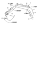
図1は、実施形態に係る作業機械100を示す斜視図である。実施形態においては、作業機械100が油圧ショベルである例について説明する。以下の説明において、作業機械100を適宜、油圧ショベル100、と称する。
[Working Machine]
Fig. 1 is a perspective view showing a
図1に示すように、油圧ショベル100は、作業機1と、油圧シリンダ2と、旋回体3と、走行体4と、操作装置5とを備える。
As shown in FIG. 1, the
旋回体3は、作業機1を支持する。旋回体3は、旋回軸RXを中心に旋回する。旋回体3は、旋回モータ(不図示)が発生する動力により旋回する。旋回体3は、運転室6と、機械室7とを有する。油圧ショベル100の運転者は、運転室6に搭乗する。運転者が着座する運転席6Sが運転室6に設けられる。
The rotating
走行体4は、旋回体3を支持する。走行体4は、一対の履帯4Cを有する。履帯4Cは、走行モータ(不図示)が発生する動力により回転する。履帯4Cの回転により油圧ショベル100が走行する。なお、走行体4は、車軸に装着されたタイヤを有してもよい。
The running
作業機1は、旋回体3に支持される。作業機1は、相対移動可能な複数の作業機要素を含む。作業機1の作業機要素は、旋回体3に連結されるブーム11と、ブーム11に連結されるアーム12と、アーム12に連結されるバケット13とを含む。
The
ブーム11と旋回体3とはブームピンを介して連結される。ブーム11は、回転軸AX1を中心に回転可能に旋回体3に支持される。
The
ブーム11とアーム12とはアームピンを介して連結される。アーム12は、回転軸AX2を中心に回転可能にブーム11に支持される。
The
アーム12とバケット13とはバケットピンを介して連結される。バケット13は、回転軸AX3を中心に回転可能にアーム12に支持される。
The
回転軸AX1と、回転軸AX2と、回転軸AX3とは、平行である。回転軸AX1と、旋回軸RXと平行な軸とは、直交する。以下の説明においては、旋回軸RXと平行な方向を適宜、旋回体3の上下方向、と称し、回転軸AX1と平行な方向を適宜、旋回体3の車幅方向又は左右方向、と称し、回転軸AX1及び旋回軸RXの両方と直交する方向を適宜、旋回体3の前後方向、と称する。旋回軸RXを基準として作業機1が存在する方向が前方向である。旋回軸RXを基準として機械室7が存在する方向が後方向である。
The rotation axis AX1, the rotation axis AX2, and the rotation axis AX3 are parallel. The rotation axis AX1 and an axis parallel to the revolving axis RX are perpendicular to each other. In the following description, the direction parallel to the revolving axis RX will be referred to as the up-down direction of the revolving
油圧シリンダ2は、作動油に基づいて作業機要素を動作させる。油圧シリンダ2は、複数の作業機要素のそれぞれを動作させるために複数設けられる。油圧シリンダ2は、ブーム11を動作させるブームシリンダ21と、アーム12を動作させるアームシリンダ22と、バケット13を動作させるバケットシリンダ23とを含む。
The
操作装置5は、油圧ショベル100の運転者に操作される。操作装置5は、作業機1及び旋回体3を動作させるために操作される。操作装置5は、運転室6に配置される。操作装置5は、複数の操作レバーを含む。操作装置5が操作されることにより、作業機1及び旋回体3が動作する。
The
[作業機の動作]
図2は、実施形態に係る作業機1の動作を説明するための模式図である。操作装置5は、作業機1及び旋回体3を動作させるために操作される。操作装置5が操作されることにより、油圧シリンダ2又は旋回モータ(不図示)が駆動する。油圧シリンダ2が駆動することにより、作業機1が動作する。旋回モータが駆動することにより、旋回体3が動作する。操作装置5が操作されることにより、ブーム11の上げ動作、ブーム11の下げ動作、アーム12の掘削動作、アーム12のダンプ動作、バケット13のダンプ動作、及びバケット13の掘削動作が実施される。操作装置5が操作されることにより、旋回体3の旋回動作が実施される。
[Operation of the work machine]
2 is a schematic diagram for explaining the operation of the
ブームシリンダ21が伸びることにより、ブーム11は上げ動作する。ブームシリンダ21が縮むことにより、ブーム11は下げ動作する。
When the
アームシリンダ22が伸びることにより、アーム12は掘削動作する。アームシリンダ22が縮むことにより、アーム12はダンプ動作する。
When the
バケットシリンダ23が伸びることにより、バケット13は掘削動作する。バケットシリンダ23が縮むことにより、バケット13はダンプ動作する。
When the
旋回モータが駆動することにより、旋回体3は旋回動作する。
When the rotation motor is driven, the
[制御システム]
図3は、実施形態に係る油圧ショベル100の制御システム10を示す模式図である。図3に示すように、制御システム10は、制御装置9と、エンジン30と、動力伝達機構31と、油圧ポンプ32と、第1流路33と、第2流路34と、タンク35と、油圧シリンダ2と、流量制御弁40と、ブリード弁50と、絞り51と、再生弁52とを備える。エンジン30、動力伝達機構31、油圧ポンプ32、及びタンク35のそれぞれは、旋回体3の機械室7に配置される。
[Control System]
Fig. 3 is a schematic diagram showing a
エンジン30は、油圧ショベル100の動力源である。エンジン30として、ディーゼルエンジンが例示される。
The
動力伝達機構31は、エンジン30が発生した動力を油圧ポンプ32に伝達する。実施形態において、油圧ポンプ32は、複数設けられる。図3に示す例において、油圧ポンプ32は、6つ設けられる。動力伝達機構31は、エンジン30が発生した動力を複数の油圧ポンプ32に分配する。
The
油圧ポンプ32は、動力伝達機構31から伝達された動力により駆動する。油圧ポンプ32は、作動油を吐出する。実施形態において、油圧ポンプ32は、可変容量型油圧ポンプである。
The
油圧シリンダ2は、油圧ポンプ32から供給された作動油に基づいて作業機要素を可動範囲で動作させる。上述のように、油圧シリンダ2は、ブーム11を動作させるブームシリンダ21と、アーム12を動作させるアームシリンダ22と、バケット13を動作させるバケットシリンダ23とを含む。
The
油圧シリンダ2は、ボトム室2Aとロッド室2Bとを有する。ボトム室2Aに作動油が供給されることにより、油圧シリンダ2は伸びる。ロッド室2Bに作動油が供給されることにより、油圧シリンダ2は縮む。
The
第1流路33は、油圧ポンプ32の吐出口に接続される。図3に示す例において、第1流路33は、2つの油圧ポンプ32の吐出口のそれぞれに接続される。油圧ポンプ32の吐出口から吐出された作動油は、第1流路33を流通することができる。油圧ポンプ32から吐出され、第1流路33を流通した作動油は、油圧シリンダ2に供給される。
The
第2流路34は、第1流路33から分岐するように設けられる。油圧ポンプ32の吐出口から吐出された作動油は、第2流路34を流通することができる。油圧ポンプ32から吐出され、第2流路34を流通した作動油は、タンク35に排出される。
The
流量制御弁40は、第1流路33を介して油圧シリンダ2に供給される作動油の流量を調整する。油圧シリンダ2のボトム室2Aは、ボトム流路36及び集合流路71を介して流量制御弁40に接続される。油圧シリンダ2のロッド室2Bは、集合流路72及びロッド流路37を介して流量制御弁40に接続される。
The
流量制御弁40は、複数設けられる。流量制御弁40は、ブームシリンダ21に供給される作動油の流量を調整するブーム流量制御弁41と、アームシリンダ22に供給される作動油の流量を調整するアーム流量制御弁42と、バケットシリンダ23に供給される作動油の流量を調整するバケット流量制御弁43とを含む。油圧ポンプ32から第1流路33に吐出された作動油は、ブーム流量制御弁41、アーム流量制御弁42、及びバケット流量制御弁43のそれぞれに供給される。
A plurality of
実施形態において、ブーム流量制御弁41、アーム流量制御弁42、及びバケット流量制御弁43のそれぞれは、複数設けられる。図3に示す例において、ブーム流量制御弁41は、3つ設けられる。アーム流量制御弁42は、3つ設けられる。バケット流量制御弁43は、3つ設けられる。
In the embodiment, a plurality of boom
流量制御弁40は、複数の油圧ポンプ32のそれぞれに接続される。3つのブーム流量制御弁41は、複数の油圧ポンプ32のそれぞれに接続される。3つのアーム流量制御弁42は、複数の油圧ポンプ32のそれぞれに接続される。3つのバケット流量制御弁43は、複数の油圧ポンプ32のそれぞれに接続される。
The
集合流路71は、ブームシリンダ21のボトム室2A、アームシリンダ22のボトム室2A、及びバケットシリンダ23のボトム室2Aのそれぞれに接続されるように、3つ設けられる。
Three collecting
集合流路72は、ブームシリンダ21のロッド室2B、アームシリンダ22のロッド室2B、及びバケットシリンダ23のロッド室2Bのそれぞれに接続されるように、3つ設けられる。
Three collecting
ボトム流路36は、3つのブーム流量制御弁41、3つのアーム流量制御弁42、及び3つのバケット流量制御弁43のそれぞれに接続されるように、9つ設けられる。
Nine
3つのブーム流量制御弁41のそれぞれに接続されたボトム流路36は、集合部36Sを介して、ブームシリンダ21のボトム室2Aに接続された集合流路71に接続される。
The
3つのアーム流量制御弁42のそれぞれに接続されたボトム流路36は、集合部36Sを介して、アームシリンダ22のボトム室2Aに接続された集合流路71に接続される。
The
3つのバケット流量制御弁43のそれぞれに接続されたボトム流路36は、集合部36Sを介して、バケットシリンダ23のボトム室2Aに接続された集合流路71に接続される。
The
ロッド流路37は、3つのブーム流量制御弁41、3つのアーム流量制御弁42、及び3つのバケット流量制御弁43のそれぞれに接続されるように、9つ設けられる。
Nine
3つのブーム流量制御弁41のそれぞれに接続されたロッド流路37は、集合部37Sを介して、ブームシリンダ21のロッド室2Bに接続された集合流路72に接続される。
The
3つのアーム流量制御弁42のそれぞれに接続されたロッド流路37は、集合部37Sを介して、アームシリンダ22のロッド室2Bに接続された集合流路72に接続される。
The
3つのバケット流量制御弁43のそれぞれに接続されたロッド流路37は、集合部37Sを介して、バケットシリンダ23のロッド室2Bに接続された集合流路72に接続される。
The
すなわち、ブームシリンダ21のボトム室2Aは、集合流路71及びボトム流路36を介して、3つのブーム流量制御弁41のそれぞれに接続される。ブームシリンダ21のロッド室2Bは、集合流路72及びロッド流路37を介して、3つのブーム流量制御弁41のそれぞれに接続される。
That is, the
アームシリンダ22のボトム室2Aは、集合流路71及びボトム流路36を介して、3つのアーム流量制御弁42のそれぞれに接続される。アームシリンダ22のロッド室2Bは、集合流路72及びロッド流路37を介して、3つのアーム流量制御弁42のそれぞれに接続される。
The
バケットシリンダ23のボトム室2Aは、集合流路71及びボトム流路36を介して、3つのバケット流量制御弁43のそれぞれに接続される。バケットシリンダ23のロッド室2Bは、集合流路72及びロッド流路37を介して、3つのバケット流量制御弁43のそれぞれに接続される。
The
油圧ポンプ32は、第1流路33を介して、ブーム流量制御弁41、アーム流量制御弁42、及びバケット流量制御弁43のそれぞれに作動油を供給することができる。ブーム流量制御弁41、アーム流量制御弁42、及びバケット流量制御弁43のそれぞれに、供給流路33Aが接続される。第1流路33は、3つの供給流路33Aのそれぞれと接続される。油圧ポンプ32から第1流路33に吐出された作動油は、供給流路33Aを介して、ブーム流量制御弁41、アーム流量制御弁42、及びバケット流量制御弁43のそれぞれに供給される。
The
ブリード弁50は、第2流路34を介してタンク35に排出される作動油の流量を調整する。ブリード弁50は、第2流路34に配置される。油圧ポンプ32は、第2流路34を介して、ブリード弁50に作動油を供給することができる。第2流路34は、油圧ポンプ32と流量制御弁40との間の第1流路33から分岐する。油圧ポンプ32から第2流路34に吐出された作動油は、流量制御弁40に供給されることなく、ブリード弁50に供給される。
The
ブリード弁50は、流入ポートPeと、流出ポートPfとを有する。
The
流入ポートPeは、第2流路34を介して油圧ポンプ32に接続される。油圧ポンプ32から吐出された作動油は、第2流路34を流通した後、流入ポートPeからブリード弁50に流入することができる。
The inlet port Pe is connected to the
流出ポートPfは、タンク流路39を介してタンク35に接続される。流出ポートPfから流出した作動油は、タンク流路39を流通した後、タンク35に排出される。
The outflow port Pf is connected to the
ブリード弁50のスプールは、タンク35に作動油を排出する排出位置P4と、作動油を流通させない停止位置P5とに移動する。
The spool of the
ブリード弁50のスプールが排出位置P4に配置されると、油圧ポンプ32から吐出された作動油は、第2流路34を流通した後、流入ポートPeからブリード弁50に流入し、流出ポートPfから流出する。流出ポートPfから流出した作動油は、タンク流路39を流通した後、タンク35に排出される。
When the spool of the
ブリード弁50のスプールが停止位置P5に配置されると、作動油は、ブリード弁50を流通することができない。
When the spool of the
ブリード弁50は、スプールの移動量により、タンク35に排出される作動油の流量を制御する。スプールの移動量により、ブリード弁50において作動油が流通するポートの開口面積が調整される。ブリード弁50の開口面積が調整されることにより、タンク35に排出される作動油の流量が調整される。
The
絞り51は、集合流路71又は集合流路72に配置される。実施形態において、絞り51は、ブームシリンダ21のボトム室2Aに接続される集合流路71に配置される。なお、絞り51は、アームシリンダ22のロッド室2B接続される集合流路72に配置されてもよい。絞り51は、バケットシリンダ23のロッド室2Bに接続される集合流路72に配置されてもよい。絞り51は、集合流路71又は集合流路72を流通する作動油の流量を調整する。絞り51は、作業機要素の自重(重力の作用)による影響を受ける集合流路に設けられる。
The
再生弁52は、集合流路71から集合流路72に再生される作動油の再生流量、又は集合流路72から集合流路71に再生される作動油の再生流量を調整する。実施形態において、再生弁52は、ブームシリンダ21のボトム室2Aに接続される集合流路71からブームシリンダ21のロッド室2Bに接続される集合流路72に再生される作動油の再生流量を調整するように配置される。なお、再生弁52は、アームシリンダ22のロッド室2Bに接続される集合流路72からアームシリンダ22のボトム室2Aに接続される集合流路71に再生される作動油の再生流量を調整するように配置されてもよい。
The
図4は、実施形態に係る油圧ショベル100の制御システム10を示す模式図である。図4は、図3のうちブームシリンダ21及びブーム流量制御弁41を抽出した図に相当する。図3に示す例では、タンデムに配置された2つの油圧ポンプ32からの作動油を合流させて、パラレルに配置された複数の流量制御弁40(41、42、43)に供給しているが、図4に示す例では、油圧ポンプ32は1つとしている。油圧ポンプ32の数は任意である。図3に示す例では、複数の油圧ポンプ32が動力伝達機構31に接続される。タンデムに配置された油圧ポンプ32から吐出された作動油が、1つの流量制御弁40を流通した後に合流して、1つの油圧シリンダ2に供給される。1つの油圧シリンダ2に供給される作動油が流通する油圧回路は、複数設けられる。図3に示す例では、それぞれの油圧回路に設けられた3つの流量制御弁40(例えば41、41、41)からの作動油を合流させて、1つの油圧シリンダ2(例えばブームシリンダ21)に供給しているが、それに限られない。1つの油圧シリンダ2に作動油を供給する流量制御弁40の数は任意である。
Figure 4 is a schematic diagram showing the
図4に示すように、制御システム10は、作動油を吐出する複数の油圧ポンプ32と、作業機要素を動作させる油圧シリンダ2と、複数の油圧ポンプ32のそれぞれに接続され油圧シリンダ2に供給される作動油の流量を調整する複数の流量制御弁40と、複数の流量制御弁40のそれぞれに接続される複数のロッド流路37と、複数のロッド流路37の集合部37Sと油圧シリンダ2のロッド室2Bの開口2Dとを接続する集合流路72と、複数の流量制御弁40のそれぞれに接続される複数のボトム流路36と、複数のボトム流路36の集合部36Sと油圧シリンダ2のボトム室2Aの開口2Cとを接続する集合流路71と、集合流路71に配置される絞り51と、を備える。
As shown in FIG. 4, the
ブーム11は、ブームシリンダ21により上げ動作及び下げ動作する。図4は、ブームシリンダ21が縮んでブーム11が下げ動作している状態を示す。ブーム11が下げ動作する場合、ブームシリンダ21のロッド室2Bに作動油が流入し、ブームシリンダ21のボトム室2Aから作動油が流出する。すなわち、油圧ポンプ32から吐出された作動油は、ブーム流量制御弁41を介してロッド流路37に流入し、集合流路72を流通した後、開口2Dを介してロッド室2Bに流入する。油圧シリンダ2のボトム室2Aの開口2Cから流出した作動油は、集合流路71及びボトム流路36を流通した後、ブーム流量制御弁41を介してタンク35に排出される。
The
以下の説明においては、ロッド流路37を適宜、供給流路37、と称し、ロッド室2Bの開口2Dを適宜、流入口2D、と称し、集合流路72を適宜、メータイン流路72、と称し、ボトム室2Aの開口2Cを適宜、流出口2C、と称し、集合流路71を適宜、メータアウト流路71、と称し、ボトム流路36を適宜、排出流路36、と称する。
In the following description, the
油圧ポンプ32は、作動油を吐出する。油圧ポンプ32は、複数設けられる。図4に示す例において、油圧ポンプ32は、3つ設けられる。1つのブーム流量制御弁41に1つの油圧ポンプ32が接続される。なお、図3に示したように、1つのブーム流量制御弁41に2つの油圧ポンプ32が接続されてもよい。
The
ブームシリンダ21は、ブーム11を動作させる。ブーム11は、ブームシリンダ21により上げ動作及び下げ動作する。ブーム11の下げ動作のときに、流入口2Dからロッド室2Bに作動油が流入し、ボトム室2Aの作動油が流出口2Cから流出する。
The
ブーム流量制御弁41は、ブームシリンダ21に供給される作動油の流量を調整する。ブーム流量制御弁41は、複数設けられる。図4に示す例において、ブーム流量制御弁41は、3つ設けられる。3つのブーム流量制御弁41は、3つの油圧ポンプ32のそれぞれに接続される。ブーム流量制御弁41と油圧ポンプ32とは1対1で対応する。
The boom
供給流路37は、ブーム流量制御弁41に接続される。供給流路37は、複数設けられる。図4に示す例において、供給流路37は、3つ設けられる。3つの供給流路37は、3つのブーム流量制御弁41のそれぞれに接続される。供給流路37とブーム流量制御弁41とは1対1で対応する。
The
供給流路37の一端部は、ブーム流量制御弁41に接続される。供給流路37の他端部は、集合部37Sにおいて集合する。供給流路37の他端部は、集合部37Sを介してメータイン流路72に接続される。複数の供給流路37のそれぞれを流通した作動油は、メータイン流路72において合流する。
One end of the
メータイン流路72は、ブーム11の下げ動作のときに作動油が流入する流入口2Dに接続される。メータイン流路72は、3つの供給流路37の集合部37Sとブームシリンダ21の作動油の流入口2Dとを接続する。複数の供給流路37のそれぞれを流通し、メータイン流路72において合流した作動油は、メータイン流路72を流通した後、流入口2Dからロッド室2Bに流入する。
The meter-in
排出流路36は、ブーム流量制御弁41に接続される。排出流路36は、複数設けられる。図4に示す例において、排出流路36は、3つ設けられる。3つの排出流路36は、3つのブーム流量制御弁41のそれぞれに接続される。排出流路36とブーム流量制御弁41とは1対1で対応する。
The
排出流路36の一端部は、ブーム流量制御弁41に接続される。排出流路36の他端部は、集合部36Sにおいて集合する。排出流路36の他端部は、集合部36Sを介してメータアウト流路71に接続される。メータアウト流路71を流通した作動油は、3つの排出流路36のそれぞれに分岐する。
One end of the
メータアウト流路71は、ブーム11の下げ動作のときに作動油が流出する流出口2Cに接続される。メータアウト流路71は、3つの排出流路36の集合部36Sとブームシリンダ21の作動油の流出口2Cとを接続する。ボトム室2Aの流出口2Cから流出した作動油は、メータアウト流路71を流通した後、複数の排出流路36のそれぞれを流通し、複数のブーム流量制御弁41のそれぞれに流入する。
The meter-out
ブーム流量制御弁41(流量制御弁40)は、ポンプポートPaと、ボトムポートPbと、ロッドポートPcと、タンクポートPdとを有する。 The boom flow control valve 41 (flow control valve 40) has a pump port Pa, a bottom port Pb, a rod port Pc, and a tank port Pd.
供給流路33Aは、ポンプポートPaに接続される。ポンプポートPaは、供給流路33Aを介して油圧ポンプ32に接続される。油圧ポンプ32から吐出された作動油は、供給流路33Aを流通した後、ポンプポートPaから流量制御弁40に流入することができる。
The
供給流路37は、ロッドポートPcに接続される。ロッドポートPcは、供給流路37及びメータイン流路72を介して油圧シリンダ2のロッド室2Bに接続される。ロッドポートPcから流出した作動油は、ロッド流路37及びメータイン流路72を流通した後、油圧シリンダ2のロッド室2Bに流入することができる。
The
排出流路36は、ボトムポートPbに接続される。ボトムポートPbは、排出流路36及びメータアウト流路71を介して油圧シリンダ2のボトム室2Aに接続される。油圧シリンダ2のボトム室2Aから流出した作動油は、メータアウト流路71及び排出流路36を流通した後、ボトムポートPbから流量制御弁40に流入することができる。
The
タンクポートPdは、排出流路38を介してタンク35に接続される。タンクポートPdから流出した作動油は、排出流路38を流通した後、タンク35に排出される。
The tank port Pd is connected to the
ブーム流量制御弁41(流量制御弁40)は、ロッド状のスプールを移動させて油圧シリンダ2に供給される作動油の流量及び方向を切り換えるスライドスプール方式の流量制御弁である。スプールが軸方向に移動することにより、ボトム室2Aに対する作動油の供給とロッド室2Bに対する作動油の供給とが切り換わる。また、スプールの移動量に基づいて、油圧シリンダ2に供給される作動油の流量が調整される。
The boom flow control valve 41 (flow control valve 40) is a slide spool type flow control valve that switches the flow rate and direction of hydraulic oil supplied to the
ブーム流量制御弁41のスプールは、油圧シリンダ2のボトム室2Aに作動油を供給する第1作動位置P1と、油圧シリンダ2のロッド室2Bに作動油を供給する第2作動位置P2と、第1作動位置P1と第2作動位置P2との間に配置され作動油を流通させない停止位置P3とに移動する。図4において、ブーム流量制御弁41のスプールは、第2作動位置P2に配置されている。
The spool of the boom
ブーム流量制御弁41のスプールが第1作動位置P1に配置されると、油圧ポンプ32から吐出された作動油は、供給流路33Aを流通した後、ポンプポートPaからブーム流量制御弁41に流入し、ボトムポートPbから流出する。ボトムポートPbから流出した作動油は、ボトム流路36及び集合流路71を流通した後、油圧シリンダ2のボトム室2Aに流入する。これにより、ブームシリンダ21は、伸びる。ブームシリンダ21が伸びると、ロッド室2Bから作動油が流出する。ブームシリンダ21のロッド室2Bから流出した作動油は、集合流路72及びロッド流路37を流通した後、ロッドポートPcからブーム流量制御弁41に流入し、タンクポートPdから流出する。タンクポートPdから流出した作動油は、排出流路38を介してタンク35に排出される。
When the spool of the boom
ブーム流量制御弁41のスプールが第2作動位置P2に配置されると、油圧ポンプ32から吐出された作動油は、供給流路33Aを流通した後、ポンプポートPaからブーム流量制御弁41に流入し、ロッドポートPcから流出する。ロッドポートPcから流出した作動油は、ロッド流路37及び集合流路72を流通した後、ブームシリンダ21のロッド室2Bに流入する。これにより、ブームシリンダ21は、縮む。ブームシリンダ21が縮むと、ボトム室2Aから作動油が流出する。ブームシリンダ21のボトム室2Aから流出した作動油は、集合流路71及びボトム流路36を流通した後、ボトムポートPbからブーム流量制御弁41に流入し、タンクポートPdから流出する。タンクポートPdから流出した作動油は、排出流路38を介してタンク35に排出される。
When the spool of the boom
ブーム流量制御弁41のスプールが停止位置P3に配置されると、作動油は、ブーム流量制御弁41を流通することができない。
When the spool of the boom
ブーム流量制御弁41は、スプールの移動量により、ブームシリンダ21に供給される作動油の流量を制御する。スプールの移動量により、ブーム流量制御弁41において作動油が流通するポートの開口面積が調整される。ブーム流量制御弁41の開口面積が調整されることにより、ブームシリンダ21に供給される作動油の流量が調整される。
The boom
絞り51は、メータアウト流路71に配置される。絞り51は、流出口2Cと集合部36Sとの間のメータアウト流路71に配置される。絞り51は、メータアウト流路71を流通する作動油の流量を調整する。絞り51の開口面積は、流出口2Cの開口面積よりも小さい。絞り51の開口面積は、ブーム流量制御弁41の最大開口面積よりも小さい。絞り51により、ブーム11の下げ動作のときにメータアウト流路71を流通する作動油の流量が規定される。
The
また、制御システム10は、メータアウト流路71からメータイン流路72に再生される作動油の再生流量を調整する再生弁52を備える。再生弁52は、メータアウト流路71の中間部とメータイン流路72の中間部とを接続する再生流路に配置される。
The
再生弁52は、流入ポートPgと、流出ポートPhとを有する。
The
流入ポートPgは、メータアウト流路71に接続される。流出口2Cから流出した作動油は、メータアウト流路71の少なくとも一部を流通した後、流入ポートPgから再生弁52に流入することができる。
The inlet port Pg is connected to the meter-out
流出ポートPhは、メータイン流路72に接続される。流出ポートPhから流出した作動油は、メータイン流路72の少なくとも一部を流通した後、流入口2Dからロッド室2Bに流入する。
The outflow port Ph is connected to the meter-in
ブーム11の下げ動作においては、ブーム11の自重(重力の作用)により、作動油の負荷圧が大きくなる可能性がある。ブーム11の自重による負荷圧を利用して、ボトム室2Aから流出した作動油の一部をロッド室2Bに戻すことにより、ブーム11の移動速度を高くすることができる。
When the
再生弁52のスプールは、作動油を流通させない停止位置P6と、作動油を再生させる再生位置P7とに移動する。
The spool of the
再生弁52のスプールが停止位置P6に配置されると、作動油は、再生弁52を流通することができない。
When the spool of the
再生弁52のスプールが再生位置P7に配置されると、メータアウト流路71の作動油の少なくとも一部は、再生弁52を介して、メータイン流路72に流入することができる。
When the spool of the
再生弁52は、スプールの移動量により、メータアウト流路71からメータイン流路72に供給される作動油の流量を示す再生流量を制御する。スプールの移動量により、再生弁52において作動油が流通するポートの開口面積が調整される。再生弁52の開口面積が調整されることにより、再生流量が調整される。
The
また、制御システム10は、供給流路37とタンク35との間に配置された吸込弁53を備える。吸込弁53は、供給流路37とタンク35との圧力差が予め定められている規定値以上になったときに、タンク35から供給流路37に作動油を流通させる。吸込弁53の流入ポートPiは、タンク35に接続される。吸込弁53の流出ポートPjは、供給流路37に接続される。
The
ブームシリンダ21のシリンダ速度は、操作装置5の操作量に基づいて決定される。操作装置5の操作量が大きいほどシリンダ速度は高くなり、操作装置5の操作量が小さいほどシリンダ速度は低くなる。ブーム11の下げ動作においては、ブーム11の自重(重力の作用)により、ブームシリンダ21のシリンダ速度は、操作装置5の操作量に基づいて指定されるシリンダ速度よりも高くなる可能性がある。すなわち、ブーム11の下げ動作においては、ブームシリンダ21は、急激に縮む可能性がある。ブームシリンダ21がブーム11の自重により急激に縮むと、油圧ポンプ32から作動油が吐出されていても、ブームシリンダ21のロッド室2Bに供給される作動油の流量が不足し、供給流路37及びメータイン流路72の圧力が急激に低下する可能性がある。油圧ポンプ32から供給される作動油が不足した場合、作動油に気泡が生成されるキャビテーション現象が発生してしまう可能性がある。吸込弁53が設けられることにより、供給流路37及びメータイン流路72の圧力が急激に低下して、供給流路37とタンク35との圧力差が規定値以上になると、吸込弁53の開口が開き、タンク35から吸込弁53を介して供給流路37に作動油が供給される。これにより、供給流路37には、油圧ポンプ32及び吸込弁53のそれぞれから作動油が供給される。したがって、作動油の不足が抑制され、キャビテーション現象の発生が抑制される。
The cylinder speed of the
また、制御システム10は、ブームシリンダ21から排出される作動油の圧力を検出する圧力センサ61と、ブームシリンダ21に流入する作動油の圧力を検出する圧力センサ62と、絞り51を通過した後の作動油の圧力を検出する圧力センサ63とを備える。
The
圧力センサ61は、メータアウト流路71を流通する作動油の圧力を検出する。圧力センサ61は、流出口2Cと絞り51との間のメータアウト流路71の作動油の圧力を検出する。実施形態において、圧力センサ61は、流出口2Cと再生弁52の流入ポートPgとの間のメータアウト流路71の作動油の圧力を検出する。
The
圧力センサ62は、メータイン流路72を流通する作動油の圧力を検出する。圧力センサ62は、再生弁52の流出ポートPhと流入口2Dとの間の作動油の圧力を検出する。
The
圧力センサ63は、メータアウト流路71を流通する作動油の圧力を検出する。圧力センサ63は、絞り51と集合部36Sとの間のメータアウト流路71の作動油の圧力を検出する。
The
[制御装置]
図5は、実施形態に係る制御装置9を示す機能ブロック図である。制御装置9は、コンピュータシステムを含む。制御装置9は、操作装置5、圧力センサ61、圧力センサ62、及び圧力センサ63のそれぞれと通信回線を介して接続される。また、制御装置9は、油圧ポンプ32、流量制御弁40、及び再生弁52のそれぞれと制御線を介して接続される。
[Control device]
5 is a functional block diagram showing the
制御装置9は、相関データ記憶部9Aと、操作指令取得部9Bと、圧力データ取得部9Cと、目標メータイン流量算出部9Dと、目標再生流量算出部9Eと、目標ポンプ流量算出部9Fと、目標メータアウト流量算出部9Gと、目標ポンプ容量算出部9Hと、制御弁開口面積算出部9Iと、再生弁開口面積算出部9Jと、ポンプ制御部9Kと、制御弁制御部9Lと、再生弁制御部9Mとを有する。
The
相関データ記憶部9Aは、操作装置5の操作量と油圧シリンダ2の流入口2Dに流入する作動油の目標流量を示す目標メータイン流量との相関データを記憶する。
The correlation data storage unit 9A stores correlation data between the operation amount of the
操作指令取得部9Bは、操作装置5の操作指令を取得する。操作装置5の操作指令は、操作装置5の操作量を含む。操作装置5の操作量は、操作レバーの傾斜角度を含む。操作装置5の操作量が最大値を示す場合、操作量は100[%]である。操作装置5が操作されていない場合、操作量は0[%]である。
The operation command acquisition unit 9B acquires an operation command for the
図6は、実施形態に係る相関データを説明するための図である。図6に示すように、操作装置5の操作量と流量制御弁40の流入口2Dに流入する目標メータイン流量Qcylとの関係を示す相関データが予め定められている。相関データは、相関データ記憶部9Aに記憶されている。
Figure 6 is a diagram for explaining correlation data according to an embodiment. As shown in Figure 6, correlation data is determined in advance that indicates the relationship between the operation amount of the
図6に示すように、相関データは、操作装置5の操作量が小さいほど目標メータイン流量Qcylが少なくなり、操作装置5の操作量が大きいほど目標メータイン流量Qcylが多くなるように定められる。
As shown in FIG. 6, the correlation data is determined so that the smaller the amount of operation of the
実施形態において、目標メータイン流量Qcylは、目標ポンプ流量Qpと、吸込流量と、目標再生流量Qrとにより規定される。目標ポンプ流量Qpは、油圧ポンプ32から吐出される作動油の目標流量を示す。吸込流量は、タンク35から吸込弁53を介して供給流路37に吸い込まれる作動油の流量である。目標再生流量Qrは、再生弁52を介してメータアウト流路71からメータイン流路72に再生される作動油の目標流量を示す。
In this embodiment, the target meter-in flow rate Qcyl is determined by the target pump flow rate Qp, the suction flow rate, and the target regeneration flow rate Qr. The target pump flow rate Qp indicates the target flow rate of hydraulic oil discharged from the
操作装置5の操作量が予め定められている値Ms未満のとき、目標メータイン流量Qcylは、目標ポンプ流量Qpと吸込流量との和により規定される。操作装置5の操作量が値Ms以上のとき、目標メータイン流量Qcylは、目標ポンプ流量Qpと吸込流量と目標再生流量Qrとの和により規定される。
When the amount of operation of the
相関データは、操作装置5の操作量が小さいほど目標ポンプ流量Qpが少なくなり、操作装置5の操作量が大きいほど目標ポンプ流量Qpが多くなるように定められる。
The correlation data is determined so that the smaller the amount of operation of the
また、操作装置5の操作量が値Ms以上のとき、相関データは、操作装置5の操作量が小さいほど目標再生流量Qrが少なくなり、操作装置5の操作量が大きいほど目標再生流量Qrが多くなるように定められる。
In addition, when the amount of operation of the
圧力データ取得部9Cは、圧力センサ61の検出データ、圧力センサ62の検出データ、及び圧力センサ63の検出データを取得する。圧力センサ61は、ブームシリンダ21の流出口2Cから流出した作動油の圧力を検出する。実施形態において、圧力センサ61は、流出口2Cと再生弁52の流入ポートPgとの間のメータアウト流路71の作動油の圧力を検出する。圧力センサ62は、油圧シリンダ2の流入口2Dに流入する作動油の圧力を検出する。実施形態において、圧力センサ62は、再生弁52の流出ポートPhと流入口2Dとの間の作動油の圧力を検出する。圧力センサ63は、メータアウト流路71を流通する作動油の圧力を検出する。実施形態において、圧力センサ63は、絞り51と集合部36Sとの間のメータアウト流路71の作動油の圧力を検出する。圧力データ取得部9Cは、圧力センサ61の検出データ、圧力センサ62の検出データ、及び圧力センサ63の検出データのそれぞれを取得する。
The pressure
目標メータイン流量算出部9Dは、相関データ記憶部9Aに記憶されている相関データと、操作指令取得部9Bにより取得された操作装置5の操作指令(操作量)とに基づいて、目標メータイン流量Qcyl[l/min.]を算出する。
The target meter-in flow
目標再生流量算出部9Eは、目標メータイン流量算出部9Dにより算出された目標メータイン流量Qcylに基づいて、作動油の目標再生流量Qr[l/min.]を算出する。目標再生流量算出部9Eは、(1)式に基づいて、目標再生流量Qrを算出する。
The target regeneration flow
![]()
![]()
(1)式において、Qstartは、再生開始流量であり、目標メータイン流量Qcylに係る閾値である。図6に示したように、再生開始流量Qstartは、操作装置5の操作量が値Msのときの目標メータイン流量Qcylに相当する。値Ms及び再生開始流量Qstartは、任意に定められる。Krは、再生流量比率を示す。再生流量比率Krは、再生弁52に係る固有の値であり、既知データである。
In equation (1), Qstart is the regeneration start flow rate and is a threshold value related to the target meter-in flow rate Qcyl. As shown in FIG. 6, the regeneration start flow rate Qstart corresponds to the target meter-in flow rate Qcyl when the operation amount of the
目標ポンプ流量算出部9Fは、目標メータイン流量算出部9Dにより算出された目標メータイン流量Qcylと、目標再生流量算出部9Eにより算出された目標再生流量Qrとに基づいて、目標ポンプ流量Qp[l/min.]を算出する。目標ポンプ流量算出部9Fは、(2)式に基づいて、目標ポンプ流量Qpを算出する。
The target pump flow
![]()
![]()
(2)式において、Ksは、吸込弁流量比率を示す。吸込弁流量比率Kwは、吸込弁53に係る固有の値であり、既知データである。
In equation (2), Ks represents the suction valve flow ratio. The suction valve flow ratio Kw is a unique value related to the
目標メータアウト流量算出部9Gは、相関データ記憶部9Aに記憶されている相関データと、操作指令取得部9Bにより取得された操作装置5の操作指令(操作量)とに基づいて、油圧シリンダ2の流出口2Cから流出する作動油の目標流量を示す目標メータアウト流量Qo[l/min.]を算出する。目標メータアウト流量算出部9Gは、(3)式に基づいて、目標メータアウト流量Qoを算出する。
The target meter-out flow rate calculation unit 9G calculates the target meter-out flow rate Qo [l/min.] indicating the target flow rate of hydraulic oil flowing out from the
![]()
![]()
(3)式において、Ao/Aiは、油圧シリンダ2の受圧面積比を示す。受圧面積比Ao/Aiは、油圧シリンダ2に係る固有の値であり、既知データである。
In equation (3), Ao/Ai indicates the pressure-receiving area ratio of the
目標ポンプ容量算出部9Hは、目標ポンプ流量算出部9Fにより算出された目標ポンプ流量Qpに基づいて、油圧ポンプ32の目標容量q[cc/rev]を算出する。目標ポンプ容量算出部9Hは、(4)式に基づいて、油圧ポンプ32の目標容量qを算出する。
The target pump

(4)式において、Neは、エンジン30の回転数[rpm]であり、hは、動力伝達機構31のギア比である。
In equation (4), Ne is the
制御弁開口面積算出部9Iは、目標メータアウト流量算出部9Gにより算出された目標メータアウト流量Qoに基づいて、流量制御弁40の目標開口面積を算出する。実施形態において、制御弁開口面積算出部9Iは、目標メータアウト流量算出部9Gにより算出された目標メータアウト流量Qoと、絞り51の開口面積Asと、油圧シリンダ2から流出した作動油の圧力Poと、絞り51と流量制御弁40との間の作動油の圧力Paと、タンク35の圧力Ptとに基づいて、流量制御弁40の目標開口面積Aoを算出する。
The control valve opening area calculation unit 9I calculates the target opening area of the
絞り弁の流量係数をCs、絞り51の開口面積をAs、油圧シリンダ2から流出した作動油の圧力をPo、絞り51と流量制御弁40との間の作動油の圧力をPaとしたとき、目標メータアウト流量Qoは、(5)式で表わすことができる。
When the flow coefficient of the throttle valve is Cs, the opening area of the
![]()
![]()
また、流量制御弁40の流量係数をCo、流量制御弁40の目標開口面積をAo、絞り51と流量制御弁40との間の作動油の圧力をPa、タンク35の作動油の圧力をPtとしたとき、目標メータアウト流量Qoは、(6)式で表わすことができる。
Furthermore, when the flow coefficient of the
![]()
![]()
圧力Poは、圧力センサ61により検出され、圧力データ取得部9Cにより取得される。圧力Paは、圧力センサ63により検出され、圧力データ取得部9Cにより取得される。圧力Ptは、大気圧とみなすことができる。流量係数Csは、絞り51に係る固有の値であり、既知データである。流量係数Coは、流量制御弁40に係る固有の値であり、既知データである。
The pressure Po is detected by the
(5)式及び(6)式からPaを消去することにより、(7)式が導出される。制御弁開口面積算出部9Iは、(7)式に基づいて、流量制御弁40の目標開口面積Aoを算出する。
By eliminating Pa from equations (5) and (6), equation (7) is derived. The control valve opening area calculation unit 9I calculates the target opening area Ao of the

目標開口面積Aoは、3つの流量制御弁40の合計の目標開口面積を示す。3つのそれぞれの流量制御弁40の目標開口面積をAo[i]とした場合、制御弁開口面積算出部9Iは、(8)式に基づいて、それぞれの流量制御弁40の目標開口面積Ao[i]を算出する。
The target opening area Ao indicates the total target opening area of the three

(8)式において、Qo[i]は、流量制御弁40[i]の目標メータアウト流量である。実施形態において、1つの油圧シリンダ2に対して3つの流量制御弁40[1]、流量制御弁40[2]、流量制御弁40[3]が設けられる。Qo[1]は、第1の流量制御弁40[1]の目標メータアウト流量である。Qo[2]は、第2の流量制御弁40[2]の目標メータアウト流量である。Qo[3]は、第3の流量制御弁40[3]の目標メータアウト流量である。
In formula (8), Qo[i] is the target meter-out flow rate of the flow control valve 40[i]. In the embodiment, three flow control valves 40[1], 40[2], and 40[3] are provided for one
再生弁開口面積算出部9Jは、目標再生流量算出部9Eにより算出された目標再生流量Qrと、流入口2Dに流入する作動油の圧力Piと、流出口2Cから流出する作動油の圧力Poとに基づいて、再生弁52の目標開口面積Arを算出する。再生弁開口面積算出部9Jは、(9)式に基づいて、再生弁52の目標開口面積Arを算出する。
The regeneration valve opening

(9)式において、Piは、油圧シリンダ2に流入する作動油の圧力である。圧力Piは、圧力センサ62により検出され、圧力データ取得部9Cにより取得される。Crは、再生弁52の流量係数である。流量係数Crは、再生弁52に係る固有の値であり、既知データである。
In equation (9), Pi is the pressure of the hydraulic oil flowing into the
ポンプ制御部9Kは、油圧ポンプ32の容量が目標ポンプ容量算出部9Hにより算出された目標容量qになるように、油圧ポンプ32を制御する制御指令を出力する。油圧ポンプ32は、容量を変更させる斜板を有する。ポンプ制御部9Kは、目標容量qになるように、斜板の角度を制御する制御指令を出力する。
The
制御弁制御部9Lは、流量制御弁40が制御弁開口面積算出部9Iにより算出された流量制御弁40の目標開口面積Aoになるように、流量制御弁40を制御する制御指令を出力する。流量制御弁40の開口面積は、スプールの移動量により調整される。制御弁制御部9Lは、目標開口面積Aoになるように、スプールの移動量を調整する電磁比例制御弁に制御指令を出力する。
The control
再生弁制御部9Mは、再生弁52が再生弁開口面積算出部9Jにより算出された再生弁52の目標開口面積Arになるように、再生弁52を制御する制御指令を出力する。
The regeneration
[作業機械の制御方法]
図7は、実施形態に係る油圧ショベル100の制御方法を示すフローチャートである。図7を用いる説明においては、主にブーム11及びブームシリンダ21の制御方法について説明する。
[Method for controlling a work machine]
7 is a flowchart showing a method for controlling the
運転者は、操作装置5を操作して、ブームシリンダ21を駆動させる。ブームシリンダ21は、ブーム11を可動範囲で動作させる。
The operator operates the
操作装置5は、運転者に操作されることにより、操作指令を出力する。操作指令は、操作装置5の操作量を含む。操作指令取得部9Bは、操作装置5の操作量を取得する(ステップS10)。
The
目標メータイン流量算出部9Dは、相関データ記憶部9Aに記憶されている相関データと操作指令取得部9Bにより取得された操作装置5の操作量とに基づいて、目標メータイン流量Qcylを算出する(ステップS20)。
The target meter-in flow
図6に示したように、相関データ記憶部9Aには、操作装置5の操作量と目標メータイン流量Qcylとの関係を示す相関データが記憶されている。相関データは、予め設定されている。図6に示したように、相関データは、操作装置5の操作量が大きくなるほど目標メータイン流量Qcylが多くなるように定められている。
As shown in FIG. 6, the correlation data storage unit 9A stores correlation data that indicates the relationship between the amount of operation of the
目標再生流量算出部9Eは、目標メータイン流量Qcylに基づいて、目標再生流量Qrを算出する。目標再生流量算出部9Eは、上述の(1)式に基づいて、目標再生流量Qrを算出する(ステップS30)。
The target regeneration flow
再生弁52は、目標メータイン流量Qcylが再生開始流量Qstart未満のときに閉じ、目標メータイン流量Qcylが再生開始流量Qstart以上のときに開くように制御される。すなわち、図6において、操作装置5の操作量が0[%]からMs[%]までのときに、再生弁52の開口は閉じる。操作装置5の操作量がMs[%]以上になり、目標メータイン流量Qcylが再生開始流量Qstart以上になったときに、再生弁52は開く。
The
目標ポンプ流量算出部9Fは、目標メータイン流量Qcylと目標再生流量Qrとに基づいて、目標ポンプ流量Qpを算出する。目標ポンプ流量算出部9Fは、上述の(2)式に基づいて、目標ポンプ流量Qpを算出する(ステップS40)。
The target pump flow
目標メータアウト流量算出部9Gは、目標メータイン流量Qcylと目標再生流量Qrとに基づいて、目標メータアウト流量Qoを算出する。目標メータアウト流量算出部9Gは、上述の(3)式に基づいて、目標メータアウト流量Qoを算出する(ステップS50)。 The target meter-out flow rate calculation unit 9G calculates the target meter-out flow rate Qo based on the target meter-in flow rate Qcyl and the target regeneration flow rate Qr. The target meter-out flow rate calculation unit 9G calculates the target meter-out flow rate Qo based on the above formula (3) (step S50).
目標ポンプ容量算出部9Hは、目標ポンプ流量Qpに基づいて、油圧ポンプ32の目標容量q[cc/rev]を算出する。目標ポンプ容量算出部9Hは、上述の(4)式に基づいて、油圧ポンプ32の目標容量qを算出する(ステップS60)。
The target pump
制御弁開口面積算出部9Iは、目標メータアウト流量Qoと絞り弁の開口面積Asと、油圧シリンダ2から流出した作動油の圧力Poと、絞り弁と流量制御弁40との間の作動油の圧力Paと、タンク35の圧力Ptとに基づいて、ブーム流量制御弁41の目標開口面積Aoを算出する。制御弁開口面積算出部9Iは、上述の(5)式、(6)式、及び(7)式に基づいて、ブーム流量制御弁41の目標開口面積Aoを算出する(ステップS70)。
The control valve opening area calculation unit 9I calculates the target opening area Ao of the boom
目標開口面積Aoは、3つのブーム流量制御弁41の合計の目標開口面積を示す。3つのそれぞれのブーム流量制御弁41の目標開口面積をAo[i]とした場合、制御弁開口面積算出部9Iは、上述の(8)式に基づいて、3つのそれぞれのブーム流量制御弁41の目標開口面積Ao[i]を算出する(ステップS80)。
The target opening area Ao indicates the total target opening area of the three boom
再生弁開口面積算出部9Jは、目標再生流量Qrに基づいて、再生弁52の目標開口面積Arを算出する。再生弁開口面積算出部9Jは、上述の(9)式に基づいて、再生弁52の目標開口面積Arを算出する(ステップS90)。
The regeneration valve opening
ポンプ制御部9Kは、油圧ポンプ32がステップS60において算出された目標容量qになるように、油圧ポンプ32を制御する制御指令を出力する。油圧ポンプ32は、容量を変更させる斜板を有する。ポンプ制御部9Kは、目標容量qになるように、斜板の角度を制御する制御指令を出力する(ステップS100)。
The
制御弁制御部9Lは、複数のブーム流量制御弁41[i]のそれぞれがステップS80において算出された目標開口面積Ao[i]になるように、ブーム流量制御弁41[i]を制御する制御指令を出力する。ブーム流量制御弁41の開口面積は、スプールの移動量により調整される。制御弁制御部9Lは、目標開口面積Ao[i]になるように、スプールの移動量を調整する電磁比例制御弁に制御指令を出力する(ステップS110)。
The control
再生弁制御部9Mは、再生弁52がステップS90において算出された目標開口面積Arになるように、再生弁52を制御する制御指令を出力する(ステップS120)。
The regeneration
[複数の油圧シリンダへの作動油の分配]
図3に示したように、油圧ポンプ32から吐出された作動油は、第1流路33を介して、ブーム流量制御弁41、アーム流量制御弁42、及びバケット流量制御弁43のそれぞれに分配される。以下、複数の油圧シリンダ2への作動油の分配について説明する。
[Distribution of hydraulic fluid to multiple hydraulic cylinders]
3, the hydraulic oil discharged from the
図8は、実施形態に係る油圧ショベル100の制御システム10を示す模式図である。図8は、図3のうちブームシリンダ21、アームシリンダ22、ブーム流量制御弁41、及びアーム流量制御弁42を抽出した図に相当する。
Figure 8 is a schematic diagram showing the
作業機要素は、ブーム11と、アーム12とを含む。油圧シリンダ2は、ブーム11を動作させるブームシリンダ21と、アーム12を動作させるアームシリンダ22とを含む。
The work machine elements include a
流量制御弁40は、優先度が定められた複数(3つ)のブーム流量制御弁41からなる第1群の流量制御弁410と、優先度が定められた複数(3つ)のアーム流量制御弁42からなる第2群の流量制御弁420とを含む。第1群の流量制御弁410は、ブームシリンダ21に供給される作動油の流量を調整する。第2群の流量制御弁420は、アームシリンダ22に供給される作動油の流量を調整する。優先度とは、各流量制御弁40において、いずれの油圧シリンダ2への作動油の供給を優先するかを予め規定したものである。なお、本実施形態においては、優先度を規定しているが、優先度を規定せずに、各流量制御弁40から均等に作動油を供給するようにしてもよい。
The
第1群の流量制御弁410は、ブーム流量制御弁41[1]と、ブーム流量制御弁41[2]と、ブーム流量制御弁41[3]とにより構成される。第1群の流量制御弁410において、ブーム流量制御弁41[1]の優先度が最も高く、ブーム流量制御弁41[1]に次いでブーム流量制御弁41[2]の優先度が高く、ブーム流量制御弁41[3]の優先度が最も低い。
The first group of
第2群の流量制御弁420は、アーム流量制御弁42[1]と、アーム流量制御弁42[2]と、アーム流量制御弁42[3]とにより構成される。第2群の流量制御弁420において、アーム流量制御弁42[3]の優先度が最も高く、アーム流量制御弁42[1]に次いでアーム流量制御弁42[2]の優先度が高く、アーム流量制御弁42[1]の優先度が最も低い。
The second group of
制御装置9は、第1群の流量制御弁410の優先度と、ブームシリンダ21の作動油の要求流量とに基づいて、第1群の流量制御弁410の開口面積を制御する分配制御部9Nを有する。
The
図8に示す例において、ブームシリンダ21の作動油の要求流量が1分間当たり1500[L]であり、アームシリンダ22の作動油の要求流量が1分間当たり1500[L]であり、3つの油圧ポンプ32のそれぞれから1分間当たり1000[L]の作動油が吐出されることとする。
In the example shown in FIG. 8, the required flow rate of hydraulic oil for the
分配制御部9Nは、第1群の流量制御弁410のうちブーム流量制御弁41[1]からブームシリンダ21に1分間当たり1000[L]の作動油が供給され、ブーム流量制御弁41[2]からブームシリンダ21に1分間当たり500[L]の作動油が供給され、ブーム流量制御弁41[3]からブームシリンダ21に作動油が供給されないように、第1群の流量制御弁410の開口面積を調整する制御指令を出力する。すなわち、分配制御部9Nは、第1群の流量制御弁410において、優先度が高いほど、ブーム流量制御弁41[i]からブームシリンダ21に供給される作動油の流量が多くなり、優先度が低いほど、ブーム流量制御弁41[i]からブームシリンダ21に供給される作動油の流量が少なくなるように、第1群の流量制御弁410の開口面積を調整する制御指令を出力する。
The
また、分配制御部9Nは、第2群の流量制御弁420のうちアーム流量制御弁42[3]からアームシリンダ22に1分間当たり1000[L]の作動油が供給され、アーム流量制御弁42[2]からアームシリンダ22に1分間当たり500[L]の作動油が供給され、アーム流量制御弁42[1]からアームシリンダ22に作動油が供給されないように、第2群の流量制御弁420の開口面積を調整する制御指令を出力する。すなわち、分配制御部9Nは、第2群の流量制御弁420において、優先度が高いほど、アーム流量制御弁42[i]からアームシリンダ22に供給される作動油の流量が多くなり、優先度が低いほど、アーム流量制御弁42[i]からアームシリンダ22に供給される作動油の流量が少なくなるように、第2群の流量制御弁420の開口面積を調整する制御指令を出力する。
The
[コンピュータシステム]
図9は、実施形態に係るコンピュータシステム1000を示すブロック図である。上述の制御装置9は、コンピュータシステム1000を含む。コンピュータシステム1000は、CPU(Central Processing Unit)のようなプロセッサ1001と、ROM(Read Only Memory)のような不揮発性メモリ及びRAM(Random Access Memory)のような揮発性メモリを含むメインメモリ1002と、ストレージ1003と、入出力回路を含むインターフェース1004とを有する。制御装置9の機能は、コンピュータプログラムとしてストレージ1003に記憶されている。プロセッサ1001は、コンピュータプログラムをストレージ1003から読み出してメインメモリ1002に展開し、コンピュータプログラムに従って上述の処理を実行する。なお、コンピュータプログラムは、ネットワークを介してコンピュータシステム1000に配信されてもよい。
[Computer System]
FIG. 9 is a block diagram showing a
コンピュータプログラムは、上述の実施形態に従って、操作装置5から出力された操作指令を取得することと、操作指令と、操作装置5の操作量と油圧シリンダ2の流入口2Dに流入する作動油の目標流量を示す目標メータイン流量Qcylとの相関データとに基づいて、油圧シリンダ2の流出口2Cから流出する作動油の目標流量を示す目標メータアウト流量Qoを算出することと、目標メータアウト流量Qoに基づいて、油圧シリンダ2に供給される作動油の流量を調整する流量制御弁40の目標開口面積を算出することと、流量制御弁40が流量制御弁40の目標開口面積になるように制御指令を出力することと、を実行することができる。
According to the above-described embodiment, the computer program can execute the following: acquire an operation command output from the operating
[効果]
以上説明したように、実施形態によれば、制御システム10は、作動油を吐出する複数の油圧ポンプ32と、ブーム11を動作させるブームシリンダ21と、複数の油圧ポンプ32のそれぞれに接続されブームシリンダ21に供給される作動油の流量を調整する複数のブーム流量制御弁41と、複数のブーム流量制御弁41のそれぞれに接続される複数の供給流路37と、複数の供給流路37の集合部37Sとブームシリンダ21の作動油の流入口2Dとを接続するメータイン流路72と、複数のブーム流量制御弁41のそれぞれに接続される複数の排出流路36と、複数の排出流路36の集合部36Sとブームシリンダ21の作動油の流出口2Cとを接続するメータアウト流路71と、メータアウト流路71に配置される絞り51と、を備える。1つのブームシリンダ21に複数のブーム流量制御弁41が接続される場合、ブームシリンダ21から流出した作動油は、メータアウト流路71を介してタンク35に排出される。絞り51がメータアウト流路71に配置されることにより、ブームシリンダ21から排出される作動油の流量が過度に制限されることが抑制される。例えば複数の排出流路36のそれぞれに絞り51が配置される場合よりも、メータアウト流路71のみに絞り51が配置される場合の方が、ブームシリンダ21から排出される作動油の流量が過度に制限されないので、ブームシリンダ21のシリンダ速度が操作装置5により指定されるシリンダ速度よりも過度に低下することが抑制される。そのため、作業効率の低下が抑制される。
[effect]
As described above, according to the embodiment, the
制御装置9は、操作装置5の操作量とブームシリンダ21の流入口2Dに流入する目標メータイン流量Qcylとの相関データを記憶する相関データ記憶部9Aと、操作装置5の操作指令を取得する操作指令取得部9Bと、相関データと操作指令とに基づいて流出口2Cから流出する作動油の目標メータアウト流量Qoを算出する目標メータアウト流量算出部9Gと、目標メータアウト流量Qoに基づいてブーム流量制御弁41の目標開口面積Aoを算出する制御弁開口面積算出部9Iと、ブーム流量制御弁41がブーム流量制御弁41の目標開口面積Aoになるように制御指令を出力する制御弁制御部9Lとを有する。目標メータアウト流量Qoに基づいてブーム流量制御弁41の目標開口面積Aoが制御されるので、ブームシリンダ21のシリンダ速度が操作装置5により指定されるシリンダ速度よりも過度に低下することが抑制される。そのため、作業効率の低下が抑制される。
The
制御装置9は、目標メータイン流量Qcylに基づいて作動油の目標再生流量Qrを算出する目標再生流量算出部9Eと、目標再生流量Qrとブームシリンダ21の流入口2Dに流入する作動油の圧力Piとブームシリンダ21の流出口2Cから流出する作動油の圧力Poとに基づいて再生弁52の目標開口面積Arを算出する再生弁開口面積算出部9Jと、再生弁52が再生弁52の目標開口面積Arになるように制御指令を出力する再生弁制御部9Mとを有する。目標再生流量Qrに基づいて再生弁52の目標開口面積が制御されるので、ブームシリンダ21のシリンダ速度が操作装置5により指定されるシリンダ速度よりも過度に低下することが抑制される。そのため、作業効率の低下が抑制される。
The
流量制御弁40は、優先度が定められた複数のブーム流量制御弁41からなる第1群の流量制御弁410と、優先度が定められた複数のアーム流量制御弁42からなる第2群の流量制御弁420とを含む。制御装置9は、第1群の流量制御弁410の優先度と、ブームシリンダ21の作動油の要求流量と、アームシリンダ22の作動油の要求流量とに基づいて、第1群の流量制御弁410の開口面積を制御する分配制御部9Nを有する。これにより、複数の油圧シリンダ2のそれぞれに適正な流量で作動油を供給することができる。
The
[その他の実施形態]
上述の実施形態においては、作業機械100が油圧ショベルであることとした。作業機械100は、作業機1を有する機械であればよく、ホイールローダでもよいし、ブルドーザでもよい。
[Other embodiments]
In the above embodiment, the
また、上述の実施形態においては、各流量制御弁40が、ブームシリンダ21とアームシリンダ22への作動油の供給の優先度を有しているが、これに限られない。バケットシリンダ23への優先度を有してもよい。
In addition, in the above embodiment, each
また、上述の実施形態においては、作動油の圧力を検出するために3個の圧力センサを有しているが、これに限られない。油圧シリンダ20に対して流出入する作動油の圧力から流量が算出できればよい。 In addition, in the above embodiment, three pressure sensors are provided to detect the pressure of the hydraulic oil, but this is not limited to this. It is sufficient if the flow rate can be calculated from the pressure of the hydraulic oil flowing in and out of the hydraulic cylinder 20.
1…作業機、2…油圧シリンダ、2A…ボトム室、2B…ロッド室、2C…流出口(開口)、2D…流入口(開口)、3…旋回体、4…走行体、4C…履帯、5…操作装置、6…運転室、6S…運転席、7…機械室、9…制御装置、9A…相関データ記憶部、9B…操作指令取得部、9C…圧力データ取得部、9D…目標メータイン流量算出部、9E…目標再生流量算出部、9F…目標ポンプ流量算出部、9G…目標メータアウト流量算出部、9H…目標ポンプ容量算出部、9I…制御弁開口面積算出部、9J…再生弁開口面積算出部、9K…ポンプ制御部、9L…制御弁制御部、9M…再生弁制御部、9N…分配制御部、10…制御システム、11…ブーム、12…アーム、13…バケット、21…ブームシリンダ、22…アームシリンダ、23…バケットシリンダ、30…エンジン、31…動力伝達機構、32…油圧ポンプ、33…第1流路、33A…供給流路、34…第2流路、35…タンク、36…ボトム流路(排出流路)、36S…集合部、37…ロッド流路(供給流路)、37S…集合部、38…排出流路、39…タンク流路、40…流量制御弁、41…ブーム流量制御弁、42…アーム流量制御弁、43…バケット流量制御弁、50…ブリード弁、51…絞り、52…再生弁、53…吸込弁、61…圧力センサ、62…圧力センサ、63…圧力センサ、71…集合流路(メータアウト流路)、72…集合流路(メータイン流路)、100…油圧ショベル(作業機械)、AX1…回転軸、AX2…回転軸、AX3…回転軸、P1…第1作動位置、P2…第2作動位置、P3…停止位置、P4…排出位置、P5…停止位置、P6…停止位置、P7…再生位置、Pa…ポンプポート、Pb…ボトムポート、Pc…ロッドポート、Pd…タンクポート、Pe…流入ポート、Pf…流出ポート、Pg…流入ポート、Ph…流出ポート、Pi…流入ポート、Pj…流出ポート、RX…旋回軸。 1...working machine, 2...hydraulic cylinder, 2A...bottom chamber, 2B...rod chamber, 2C...outlet (opening), 2D...inlet (opening), 3...rotating body, 4...traveling body, 4C...track, 5...operating device, 6...driver's cab, 6S...driver's seat, 7...machine room, 9...control device, 9A...correlation data storage unit, 9B...operation command acquisition unit, 9C...pressure data acquisition unit, 9D...target meter-in flow rate calculation unit, 9E...target regeneration flow rate calculation unit, 9F...target pump flow rate calculation unit, 9G...target meter-out flow rate calculation unit, 9H... Target pump capacity calculation unit, 9I...control valve opening area calculation unit, 9J...regeneration valve opening area calculation unit, 9K...pump control unit, 9L...control valve control unit, 9M...regeneration valve control unit, 9N...distribution control unit, 10...control system, 11...boom, 12...arm, 13...bucket, 21...boom cylinder, 22...arm cylinder, 23...bucket cylinder, 30...engine, 31...power transmission mechanism, 32...hydraulic pump, 33...first flow path, 33A...supply flow path, 34...second flow path, 35...tank , 36... bottom flow path (discharge flow path), 36S... collecting section, 37... rod flow path (supply flow path), 37S... collecting section, 38... discharge flow path, 39... tank flow path, 40... flow control valve, 41... boom flow control valve, 42... arm flow control valve, 43... bucket flow control valve, 50... bleed valve, 51... throttle, 52... regeneration valve, 53... suction valve, 61... pressure sensor, 62... pressure sensor, 63... pressure sensor, 71... collecting flow path (meter-out flow path), 72... collecting flow path (meter-in flow path), 1 00...hydraulic excavator (work machine), AX1...rotating shaft, AX2...rotating shaft, AX3...rotating shaft, P1...first operating position, P2...second operating position, P3...stop position, P4...discharge position, P5...stop position, P6...stop position, P7...regeneration position, Pa...pump port, Pb...bottom port, Pc...rod port, Pd...tank port, Pe...inlet port, Pf...outlet port, Pg...inlet port, Ph...outlet port, Pi...inlet port, Pj...outlet port, RX...swivel shaft.
Claims (7)
作業機要素を動作させる油圧シリンダと、
複数の前記油圧ポンプのそれぞれに接続され前記油圧シリンダに供給される前記作動油の流量を調整する複数の流量制御弁と、
複数の前記流量制御弁のそれぞれに接続される複数の供給流路と、
複数の前記供給流路の集合部と前記油圧シリンダの前記作動油の流入口とを接続するメータイン流路と、
複数の前記流量制御弁のそれぞれに接続される複数の排出流路と、
複数の前記排出流路の集合部と前記油圧シリンダの前記作動油の流出口とを接続するメータアウト流路と、
前記メータアウト流路に配置される絞りと、
操作により操作指令を生成する操作装置と、
制御装置と、を備え、
前記制御装置は、
前記操作装置の操作量と前記流入口に流入する前記作動油の目標流量を示す目標メータイン流量との相関データを記憶する相関データ記憶部と、
前記操作指令を取得する操作指令取得部と、
前記相関データと前記操作指令とに基づいて前記流出口から流出する前記作動油の目標流量を示す目標メータアウト流量を算出する目標メータアウト流量算出部と、
前記目標メータアウト流量に基づいて前記流量制御弁の目標開口面積を算出する制御弁開口面積算出部と、
前記流量制御弁が前記流量制御弁の目標開口面積になるように制御指令を出力する制御弁制御部と、を有する、
作業機械の制御システム。 A plurality of hydraulic pumps that discharge hydraulic oil;
A hydraulic cylinder for operating the working machine element;
a plurality of flow control valves connected to the plurality of hydraulic pumps, respectively, for adjusting the flow rate of the hydraulic oil supplied to the hydraulic cylinder;
A plurality of supply flow paths connected to the plurality of flow control valves, respectively;
a meter-in flow passage connecting a collection portion of the plurality of supply flow passages and an inlet of the hydraulic oil of the hydraulic cylinder;
A plurality of discharge flow paths connected to the plurality of flow control valves, respectively;
a meter-out flow passage connecting a collection portion of the plurality of discharge flow passages and an outlet port of the hydraulic cylinder for the hydraulic oil;
A throttle disposed in the meter-out flow path;
an operation device that generates an operation command through an operation;
A control device ,
The control device includes:
a correlation data storage unit configured to store correlation data between an operation amount of the operating device and a target meter-in flow rate indicating a target flow rate of the hydraulic oil flowing into the inlet;
an operation command acquisition unit for acquiring the operation command;
a target meter-out flow rate calculation unit that calculates a target meter-out flow rate indicating a target flow rate of the hydraulic oil flowing out from the outlet based on the correlation data and the operation command;
a control valve opening area calculation unit that calculates a target opening area of the flow control valve based on the target meter-out flow rate;
a control valve control unit that outputs a control command so that the flow control valve becomes the target opening area of the flow control valve,
Work machine control system.
前記メータアウト流路は、前記下げ動作のときに前記作動油が流出する前記流出口に接続される、
請求項1に記載の作業機械の制御システム。 The working machine element is raised and lowered by the hydraulic cylinder,
The meter-out passage is connected to the outlet through which the hydraulic oil flows out during the lowering operation.
2. A control system for a work machine according to claim 1.
請求項2に記載の作業機械の制御システム。 The opening area of the throttle is smaller than the maximum opening area of the flow control valve.
3. A control system for a work machine according to claim 2.
前記制御装置は、
前記目標メータイン流量に基づいて前記作動油の目標再生流量を算出する目標再生流量算出部と、
前記目標再生流量と前記流入口に流入する前記作動油の圧力と前記流出口から流出する前記作動油の圧力とに基づいて前記再生弁の目標開口面積を算出する再生弁開口面積算出部と、
前記再生弁が前記再生弁の目標開口面積になるように制御指令を出力する再生弁制御部と、を有する、
請求項1から請求項3のいずれか一項に記載の作業機械の制御システム。 a regeneration valve for adjusting a regeneration flow rate of the hydraulic oil regenerated from the meter-out passage to the meter-in passage,
The control device includes:
a target regeneration flow rate calculation unit that calculates a target regeneration flow rate of the hydraulic oil based on the target meter-in flow rate;
a regeneration valve opening area calculation unit that calculates a target opening area of the regeneration valve based on the target regeneration flow rate, the pressure of the hydraulic oil flowing into the inlet, and the pressure of the hydraulic oil flowing out from the outlet;
A regeneration valve control unit that outputs a control command so that the regeneration valve becomes the target opening area of the regeneration valve.
A control system for a work machine according to any one of claims 1 to 3 .
前記油圧シリンダは、前記第1作業機要素を動作させる第1油圧シリンダと、前記第2作業機要素を動作させる第2油圧シリンダと、を含み、
前記流量制御弁は、優先度が定められた複数の流量制御弁からなる第1群の流量制御弁と、優先度が定められた複数の流量制御弁からなる第2群の流量制御弁と、を含み、
前記第1群の流量制御弁は、前記第1油圧シリンダに供給される前記作動油の流量を調整し、
前記第2群の流量制御弁は、前記第2油圧シリンダに供給される前記作動油の流量を調整し、
前記制御装置は、
前記第1群の流量制御弁の優先度と、前記第1油圧シリンダの作動油の要求流量とに基づいて、前記第1群の流量制御弁の開口面積を制御する分配制御部を有する、
請求項1から請求項4のいずれか一項に記載の作業機械の制御システム。 The work machine element includes a first work machine element and a second work machine element,
The hydraulic cylinder includes a first hydraulic cylinder that operates the first work machine element and a second hydraulic cylinder that operates the second work machine element,
the flow control valves include a first group of flow control valves consisting of a plurality of flow control valves whose priorities are determined, and a second group of flow control valves consisting of a plurality of flow control valves whose priorities are determined,
The first group of flow control valves adjusts the flow rate of the hydraulic oil supplied to the first hydraulic cylinder,
the second group of flow control valves adjusts the flow rate of the hydraulic oil supplied to the second hydraulic cylinder;
The control device includes:
a distribution control unit that controls an opening area of the first group of flow control valves based on a priority of the first group of flow control valves and a required flow rate of the hydraulic oil of the first hydraulic cylinder,
A control system for a work machine according to any one of claims 1 to 4 .
複数の前記作業機要素のそれぞれを動作させる複数の油圧シリンダと、
請求項1から請求項5のいずれか一項に記載の作業機械の制御システムと、を備える、
作業機械。 A work machine including a plurality of work machine elements;
A plurality of hydraulic cylinders for operating each of the plurality of work machine elements;
A work machine control system according to any one of claims 1 to 5 .
Working machinery.
前記操作指令と、前記操作装置の操作量と油圧シリンダの流入口に流入する作動油の目標流量を示す目標メータイン流量との相関データとに基づいて、前記油圧シリンダの流出口から流出する前記作動油の目標流量を示す目標メータアウト流量を算出することと、
前記目標メータアウト流量に基づいて、前記油圧シリンダに供給される前記作動油の流量を調整する流量制御弁の目標開口面積を算出することと、
前記流量制御弁が前記流量制御弁の目標開口面積になるように制御指令を出力することと、を含む、
作業機械の制御方法。 Obtaining an operation command output from an operation device;
Calculating a target meter-out flow rate indicating a target flow rate of the hydraulic oil flowing out from an outlet of the hydraulic cylinder based on the operation command and correlation data between an operation amount of the operating device and a target meter-in flow rate indicating a target flow rate of the hydraulic oil flowing into an inlet of the hydraulic cylinder;
Calculating a target opening area of a flow control valve that adjusts the flow rate of the hydraulic oil supplied to the hydraulic cylinder based on the target meter-out flow rate;
and outputting a control command so that the flow control valve has a target opening area of the flow control valve.
A method for controlling a work machine.
Priority Applications (6)
| Application Number | Priority Date | Filing Date | Title |
|---|---|---|---|
| JP2019239545A JP7473337B2 (en) | 2019-12-27 | 2019-12-27 | CONTROL SYSTEM FOR WORK MACHINE, CONTROL MACHINE, AND CONTROL METHOD FOR WORK MACHINE |
| US17/788,077 US12173477B2 (en) | 2019-12-27 | 2020-12-09 | Work machine control system, work machine, and work machine control method |
| AU2020414631A AU2020414631B2 (en) | 2019-12-27 | 2020-12-09 | Work machine control system, work machine, and work machine control method |
| DE112020005331.8T DE112020005331T5 (en) | 2019-12-27 | 2020-12-09 | Control system for a work machine, work machine and method for controlling a work machine |
| PCT/JP2020/045857 WO2021131701A1 (en) | 2019-12-27 | 2020-12-09 | Control system for work machine, work machine, and control method for work machine |
| JP2024064179A JP7668927B2 (en) | 2019-12-27 | 2024-04-11 | System and method for controlling a work machine |
Applications Claiming Priority (1)
| Application Number | Priority Date | Filing Date | Title |
|---|---|---|---|
| JP2019239545A JP7473337B2 (en) | 2019-12-27 | 2019-12-27 | CONTROL SYSTEM FOR WORK MACHINE, CONTROL MACHINE, AND CONTROL METHOD FOR WORK MACHINE |
Related Child Applications (1)
| Application Number | Title | Priority Date | Filing Date |
|---|---|---|---|
| JP2024064179A Division JP7668927B2 (en) | 2019-12-27 | 2024-04-11 | System and method for controlling a work machine |
Publications (2)
| Publication Number | Publication Date |
|---|---|
| JP2021107729A JP2021107729A (en) | 2021-07-29 |
| JP7473337B2 true JP7473337B2 (en) | 2024-04-23 |
Family
ID=76575477
Family Applications (2)
| Application Number | Title | Priority Date | Filing Date |
|---|---|---|---|
| JP2019239545A Active JP7473337B2 (en) | 2019-12-27 | 2019-12-27 | CONTROL SYSTEM FOR WORK MACHINE, CONTROL MACHINE, AND CONTROL METHOD FOR WORK MACHINE |
| JP2024064179A Active JP7668927B2 (en) | 2019-12-27 | 2024-04-11 | System and method for controlling a work machine |
Family Applications After (1)
| Application Number | Title | Priority Date | Filing Date |
|---|---|---|---|
| JP2024064179A Active JP7668927B2 (en) | 2019-12-27 | 2024-04-11 | System and method for controlling a work machine |
Country Status (5)
| Country | Link |
|---|---|
| US (1) | US12173477B2 (en) |
| JP (2) | JP7473337B2 (en) |
| AU (1) | AU2020414631B2 (en) |
| DE (1) | DE112020005331T5 (en) |
| WO (1) | WO2021131701A1 (en) |
Families Citing this family (7)
| Publication number | Priority date | Publication date | Assignee | Title |
|---|---|---|---|---|
| KR102661855B1 (en) * | 2020-03-30 | 2024-04-30 | 히다치 겡키 가부시키 가이샤 | working machine |
| KR102706842B1 (en) * | 2020-04-02 | 2024-09-19 | 히다치 겡키 가부시키 가이샤 | work machine |
| KR20240026894A (en) | 2021-06-29 | 2024-02-29 | 타이세이카코 카부시키가이샤 | syringe |
| CN117836521A (en) * | 2022-01-25 | 2024-04-05 | 日立建机株式会社 | Working machinery |
| JP7346647B1 (en) * | 2022-03-31 | 2023-09-19 | 日立建機株式会社 | working machine |
| JP2024043388A (en) * | 2022-09-16 | 2024-03-29 | 住友重機械工業株式会社 | excavator |
| GB2630376A (en) * | 2023-05-26 | 2024-11-27 | Caterpillar Sarl | Hydraulic system |
Citations (3)
| Publication number | Priority date | Publication date | Assignee | Title |
|---|---|---|---|---|
| JP2010275818A (en) | 2009-05-29 | 2010-12-09 | Hitachi Constr Mach Co Ltd | Hydraulic drive unit for construction machine |
| JP2014098403A (en) | 2012-11-13 | 2014-05-29 | Kobe Steel Ltd | Hydraulic drive device for work machine |
| JP2018028358A (en) | 2016-08-18 | 2018-02-22 | 日立建機株式会社 | Hydraulic control device of construction machine |
Family Cites Families (19)
| Publication number | Priority date | Publication date | Assignee | Title |
|---|---|---|---|---|
| JPS4710283U (en) * | 1971-03-01 | 1972-10-06 | ||
| EP1380756B1 (en) * | 2001-04-17 | 2011-08-31 | Caterpillar SARL | Fluid pressure circuit |
| JP3900949B2 (en) * | 2002-02-04 | 2007-04-04 | コベルコ建機株式会社 | Control device and control method for hydraulic work machine |
| DE102004012382B4 (en) * | 2004-03-13 | 2014-03-13 | Deere & Company | Hydraulic arrangement |
| GB0614534D0 (en) * | 2006-07-21 | 2006-08-30 | Artemis Intelligent Power Ltd | Fluid power distribution and control system |
| US7487707B2 (en) * | 2006-09-27 | 2009-02-10 | Husco International, Inc. | Hydraulic valve assembly with a pressure compensated directional spool valve and a regeneration shunt valve |
| JP2010286074A (en) | 2009-06-12 | 2010-12-24 | Kobe Steel Ltd | Hydraulic control device of working machine and working machine having the same |
| JP5530728B2 (en) | 2010-01-20 | 2014-06-25 | 株式会社神戸製鋼所 | Hydraulic control device and hydraulic work machine equipped with the same |
| JP5828481B2 (en) * | 2012-07-25 | 2015-12-09 | Kyb株式会社 | Construction machine control equipment |
| JP5908371B2 (en) * | 2012-08-15 | 2016-04-26 | Kyb株式会社 | Control device for hybrid construction machine |
| US9845813B2 (en) * | 2012-09-20 | 2017-12-19 | Hitachi Construction Machinery Co., Ltd. | Driving device for work machine and work machine equipped therewith |
| EP2786959B1 (en) * | 2013-04-05 | 2017-05-10 | Bosch Rexroth Oil Control S.p.A. | Anti cavitation device for a hydraulic cylinder |
| JP2017015118A (en) * | 2015-06-29 | 2017-01-19 | Kyb株式会社 | Control system of construction machine |
| US10316866B2 (en) * | 2016-03-10 | 2019-06-11 | Hitachi Construction Machinery Co., Ltd. | Construction machine |
| JP6549543B2 (en) * | 2016-09-29 | 2019-07-24 | 日立建機株式会社 | Hydraulic drive of work machine |
| JP6789843B2 (en) * | 2017-02-17 | 2020-11-25 | ヤンマーパワーテクノロジー株式会社 | Control device for hydraulic machinery |
| JP6707064B2 (en) * | 2017-08-24 | 2020-06-10 | 日立建機株式会社 | Hydraulic work machine |
| US11143210B1 (en) * | 2020-08-24 | 2021-10-12 | Anatoly Deninovich Lee | High-low hydraulic system for balers, compactors and transfer station compactors |
| US11608610B2 (en) * | 2021-08-04 | 2023-03-21 | Caterpillar Inc. | Control of a hydraulic system |
-
2019
- 2019-12-27 JP JP2019239545A patent/JP7473337B2/en active Active
-
2020
- 2020-12-09 US US17/788,077 patent/US12173477B2/en active Active
- 2020-12-09 WO PCT/JP2020/045857 patent/WO2021131701A1/en not_active Ceased
- 2020-12-09 DE DE112020005331.8T patent/DE112020005331T5/en active Pending
- 2020-12-09 AU AU2020414631A patent/AU2020414631B2/en active Active
-
2024
- 2024-04-11 JP JP2024064179A patent/JP7668927B2/en active Active
Patent Citations (3)
| Publication number | Priority date | Publication date | Assignee | Title |
|---|---|---|---|---|
| JP2010275818A (en) | 2009-05-29 | 2010-12-09 | Hitachi Constr Mach Co Ltd | Hydraulic drive unit for construction machine |
| JP2014098403A (en) | 2012-11-13 | 2014-05-29 | Kobe Steel Ltd | Hydraulic drive device for work machine |
| JP2018028358A (en) | 2016-08-18 | 2018-02-22 | 日立建機株式会社 | Hydraulic control device of construction machine |
Also Published As
| Publication number | Publication date |
|---|---|
| US20230022248A1 (en) | 2023-01-26 |
| AU2020414631A1 (en) | 2022-06-30 |
| JP7668927B2 (en) | 2025-04-25 |
| AU2020414631B2 (en) | 2024-01-11 |
| US12173477B2 (en) | 2024-12-24 |
| WO2021131701A1 (en) | 2021-07-01 |
| JP2021107729A (en) | 2021-07-29 |
| JP2024083559A (en) | 2024-06-21 |
| DE112020005331T5 (en) | 2022-08-25 |
Similar Documents
| Publication | Publication Date | Title |
|---|---|---|
| JP7668927B2 (en) | System and method for controlling a work machine | |
| EP2910795B1 (en) | Work machine | |
| US7559197B2 (en) | Combiner valve control system and method | |
| US8483916B2 (en) | Hydraulic control system implementing pump torque limiting | |
| US7797934B2 (en) | Anti-stall system utilizing implement pilot relief | |
| US9091286B2 (en) | Hydraulic control system having electronic flow limiting | |
| US8899143B2 (en) | Hydraulic control system having variable pressure relief | |
| CN111989441B (en) | Hydraulic shovel drive system | |
| JP2024025818A (en) | excavator | |
| CN114555957A (en) | Regeneration device, hydraulic drive system provided with regeneration device, and control device for hydraulic drive system | |
| US8209094B2 (en) | Hydraulic implement system having boom priority | |
| US20140283915A1 (en) | Hydraulic Control System Having Relief Flow Capture | |
| JP2018145984A (en) | Hydraulic transmission for construction machine | |
| CN115045874A (en) | Hydraulic system | |
| US20170145660A1 (en) | Divided Pump Implement Valve and System | |
| JP7788568B2 (en) | Work machinery | |
| JP7797355B2 (en) | Hydraulic control device, hydraulic circuit control method, and hydraulic device | |
| CN114746612A (en) | Working machine | |
| JP7615936B2 (en) | Construction Machinery | |
| JP6896528B2 (en) | Excavator |
Legal Events
| Date | Code | Title | Description |
|---|---|---|---|
| A621 | Written request for application examination |
Free format text: JAPANESE INTERMEDIATE CODE: A621 Effective date: 20221108 |
|
| A131 | Notification of reasons for refusal |
Free format text: JAPANESE INTERMEDIATE CODE: A131 Effective date: 20231017 |
|
| A521 | Request for written amendment filed |
Free format text: JAPANESE INTERMEDIATE CODE: A523 Effective date: 20231212 |
|
| TRDD | Decision of grant or rejection written | ||
| A01 | Written decision to grant a patent or to grant a registration (utility model) |
Free format text: JAPANESE INTERMEDIATE CODE: A01 Effective date: 20240312 |
|
| A61 | First payment of annual fees (during grant procedure) |
Free format text: JAPANESE INTERMEDIATE CODE: A61 Effective date: 20240411 |
|
| R150 | Certificate of patent or registration of utility model |
Ref document number: 7473337 Country of ref document: JP Free format text: JAPANESE INTERMEDIATE CODE: R150 |