JP6707064B2 - Hydraulic work machine - Google Patents
Hydraulic work machine Download PDFInfo
- Publication number
- JP6707064B2 JP6707064B2 JP2017161634A JP2017161634A JP6707064B2 JP 6707064 B2 JP6707064 B2 JP 6707064B2 JP 2017161634 A JP2017161634 A JP 2017161634A JP 2017161634 A JP2017161634 A JP 2017161634A JP 6707064 B2 JP6707064 B2 JP 6707064B2
- Authority
- JP
- Japan
- Prior art keywords
- arm
- boom
- control valve
- cylinder
- hydraulic
- Prior art date
- Legal status (The legal status is an assumption and is not a legal conclusion. Google has not performed a legal analysis and makes no representation as to the accuracy of the status listed.)
- Active
Links
Images


Classifications
-
- E—FIXED CONSTRUCTIONS
- E02—HYDRAULIC ENGINEERING; FOUNDATIONS; SOIL SHIFTING
- E02F—DREDGING; SOIL-SHIFTING
- E02F9/00—Component parts of dredgers or soil-shifting machines, not restricted to one of the kinds covered by groups E02F3/00 - E02F7/00
- E02F9/20—Drives; Control devices
- E02F9/22—Hydraulic or pneumatic drives
- E02F9/2221—Control of flow rate; Load sensing arrangements
- E02F9/2239—Control of flow rate; Load sensing arrangements using two or more pumps with cross-assistance
- E02F9/2242—Control of flow rate; Load sensing arrangements using two or more pumps with cross-assistance including an electronic controller
-
- E—FIXED CONSTRUCTIONS
- E02—HYDRAULIC ENGINEERING; FOUNDATIONS; SOIL SHIFTING
- E02F—DREDGING; SOIL-SHIFTING
- E02F3/00—Dredgers; Soil-shifting machines
- E02F3/04—Dredgers; Soil-shifting machines mechanically-driven
- E02F3/28—Dredgers; Soil-shifting machines mechanically-driven with digging tools mounted on a dipper- or bucket-arm, i.e. there is either one arm or a pair of arms, e.g. dippers, buckets
- E02F3/36—Component parts
- E02F3/42—Drives for dippers, buckets, dipper-arms or bucket-arms
- E02F3/43—Control of dipper or bucket position; Control of sequence of drive operations
- E02F3/435—Control of dipper or bucket position; Control of sequence of drive operations for dipper-arms, backhoes or the like
- E02F3/437—Control of dipper or bucket position; Control of sequence of drive operations for dipper-arms, backhoes or the like providing automatic sequences of movements, e.g. linear excavation, keeping dipper angle constant
-
- E—FIXED CONSTRUCTIONS
- E02—HYDRAULIC ENGINEERING; FOUNDATIONS; SOIL SHIFTING
- E02F—DREDGING; SOIL-SHIFTING
- E02F9/00—Component parts of dredgers or soil-shifting machines, not restricted to one of the kinds covered by groups E02F3/00 - E02F7/00
- E02F9/20—Drives; Control devices
- E02F9/22—Hydraulic or pneumatic drives
- E02F9/2264—Arrangements or adaptations of elements for hydraulic drives
- E02F9/2267—Valves or distributors
-
- E—FIXED CONSTRUCTIONS
- E02—HYDRAULIC ENGINEERING; FOUNDATIONS; SOIL SHIFTING
- E02F—DREDGING; SOIL-SHIFTING
- E02F9/00—Component parts of dredgers or soil-shifting machines, not restricted to one of the kinds covered by groups E02F3/00 - E02F7/00
- E02F9/20—Drives; Control devices
- E02F9/22—Hydraulic or pneumatic drives
- E02F9/2278—Hydraulic circuits
- E02F9/2282—Systems using center bypass type changeover valves
-
- E—FIXED CONSTRUCTIONS
- E02—HYDRAULIC ENGINEERING; FOUNDATIONS; SOIL SHIFTING
- E02F—DREDGING; SOIL-SHIFTING
- E02F9/00—Component parts of dredgers or soil-shifting machines, not restricted to one of the kinds covered by groups E02F3/00 - E02F7/00
- E02F9/20—Drives; Control devices
- E02F9/22—Hydraulic or pneumatic drives
- E02F9/2278—Hydraulic circuits
- E02F9/2285—Pilot-operated systems
-
- E—FIXED CONSTRUCTIONS
- E02—HYDRAULIC ENGINEERING; FOUNDATIONS; SOIL SHIFTING
- E02F—DREDGING; SOIL-SHIFTING
- E02F9/00—Component parts of dredgers or soil-shifting machines, not restricted to one of the kinds covered by groups E02F3/00 - E02F7/00
- E02F9/20—Drives; Control devices
- E02F9/22—Hydraulic or pneumatic drives
- E02F9/2278—Hydraulic circuits
- E02F9/2292—Systems with two or more pumps
-
- F—MECHANICAL ENGINEERING; LIGHTING; HEATING; WEAPONS; BLASTING
- F15—FLUID-PRESSURE ACTUATORS; HYDRAULICS OR PNEUMATICS IN GENERAL
- F15B—SYSTEMS ACTING BY MEANS OF FLUIDS IN GENERAL; FLUID-PRESSURE ACTUATORS, e.g. SERVOMOTORS; DETAILS OF FLUID-PRESSURE SYSTEMS, NOT OTHERWISE PROVIDED FOR
- F15B11/00—Servomotor systems without provision for follow-up action; Circuits therefor
- F15B11/02—Systems essentially incorporating special features for controlling the speed or actuating force of an output member
- F15B11/028—Systems essentially incorporating special features for controlling the speed or actuating force of an output member for controlling the actuating force
-
- F—MECHANICAL ENGINEERING; LIGHTING; HEATING; WEAPONS; BLASTING
- F15—FLUID-PRESSURE ACTUATORS; HYDRAULICS OR PNEUMATICS IN GENERAL
- F15B—SYSTEMS ACTING BY MEANS OF FLUIDS IN GENERAL; FLUID-PRESSURE ACTUATORS, e.g. SERVOMOTORS; DETAILS OF FLUID-PRESSURE SYSTEMS, NOT OTHERWISE PROVIDED FOR
- F15B11/00—Servomotor systems without provision for follow-up action; Circuits therefor
- F15B11/02—Systems essentially incorporating special features for controlling the speed or actuating force of an output member
- F15B11/04—Systems essentially incorporating special features for controlling the speed or actuating force of an output member for controlling the speed
- F15B11/044—Systems essentially incorporating special features for controlling the speed or actuating force of an output member for controlling the speed by means in the return line, i.e. "meter out"
-
- F—MECHANICAL ENGINEERING; LIGHTING; HEATING; WEAPONS; BLASTING
- F15—FLUID-PRESSURE ACTUATORS; HYDRAULICS OR PNEUMATICS IN GENERAL
- F15B—SYSTEMS ACTING BY MEANS OF FLUIDS IN GENERAL; FLUID-PRESSURE ACTUATORS, e.g. SERVOMOTORS; DETAILS OF FLUID-PRESSURE SYSTEMS, NOT OTHERWISE PROVIDED FOR
- F15B11/00—Servomotor systems without provision for follow-up action; Circuits therefor
- F15B11/16—Servomotor systems without provision for follow-up action; Circuits therefor with two or more servomotors
- F15B11/17—Servomotor systems without provision for follow-up action; Circuits therefor with two or more servomotors using two or more pumps
-
- F—MECHANICAL ENGINEERING; LIGHTING; HEATING; WEAPONS; BLASTING
- F15—FLUID-PRESSURE ACTUATORS; HYDRAULICS OR PNEUMATICS IN GENERAL
- F15B—SYSTEMS ACTING BY MEANS OF FLUIDS IN GENERAL; FLUID-PRESSURE ACTUATORS, e.g. SERVOMOTORS; DETAILS OF FLUID-PRESSURE SYSTEMS, NOT OTHERWISE PROVIDED FOR
- F15B2211/00—Circuits for servomotor systems
- F15B2211/20—Fluid pressure source, e.g. accumulator or variable axial piston pump
- F15B2211/205—Systems with pumps
- F15B2211/20576—Systems with pumps with multiple pumps
-
- F—MECHANICAL ENGINEERING; LIGHTING; HEATING; WEAPONS; BLASTING
- F15—FLUID-PRESSURE ACTUATORS; HYDRAULICS OR PNEUMATICS IN GENERAL
- F15B—SYSTEMS ACTING BY MEANS OF FLUIDS IN GENERAL; FLUID-PRESSURE ACTUATORS, e.g. SERVOMOTORS; DETAILS OF FLUID-PRESSURE SYSTEMS, NOT OTHERWISE PROVIDED FOR
- F15B2211/00—Circuits for servomotor systems
- F15B2211/30—Directional control
- F15B2211/305—Directional control characterised by the type of valves
- F15B2211/3056—Assemblies of multiple valves
- F15B2211/30565—Assemblies of multiple valves having multiple valves for a single output member, e.g. for creating higher valve function by use of multiple valves like two 2/2-valves replacing a 5/3-valve
-
- F—MECHANICAL ENGINEERING; LIGHTING; HEATING; WEAPONS; BLASTING
- F15—FLUID-PRESSURE ACTUATORS; HYDRAULICS OR PNEUMATICS IN GENERAL
- F15B—SYSTEMS ACTING BY MEANS OF FLUIDS IN GENERAL; FLUID-PRESSURE ACTUATORS, e.g. SERVOMOTORS; DETAILS OF FLUID-PRESSURE SYSTEMS, NOT OTHERWISE PROVIDED FOR
- F15B2211/00—Circuits for servomotor systems
- F15B2211/30—Directional control
- F15B2211/35—Directional control combined with flow control
- F15B2211/351—Flow control by regulating means in feed line, i.e. meter-in control
-
- F—MECHANICAL ENGINEERING; LIGHTING; HEATING; WEAPONS; BLASTING
- F15—FLUID-PRESSURE ACTUATORS; HYDRAULICS OR PNEUMATICS IN GENERAL
- F15B—SYSTEMS ACTING BY MEANS OF FLUIDS IN GENERAL; FLUID-PRESSURE ACTUATORS, e.g. SERVOMOTORS; DETAILS OF FLUID-PRESSURE SYSTEMS, NOT OTHERWISE PROVIDED FOR
- F15B2211/00—Circuits for servomotor systems
- F15B2211/30—Directional control
- F15B2211/35—Directional control combined with flow control
- F15B2211/353—Flow control by regulating means in return line, i.e. meter-out control
-
- F—MECHANICAL ENGINEERING; LIGHTING; HEATING; WEAPONS; BLASTING
- F15—FLUID-PRESSURE ACTUATORS; HYDRAULICS OR PNEUMATICS IN GENERAL
- F15B—SYSTEMS ACTING BY MEANS OF FLUIDS IN GENERAL; FLUID-PRESSURE ACTUATORS, e.g. SERVOMOTORS; DETAILS OF FLUID-PRESSURE SYSTEMS, NOT OTHERWISE PROVIDED FOR
- F15B2211/00—Circuits for servomotor systems
- F15B2211/40—Flow control
- F15B2211/415—Flow control characterised by the connections of the flow control means in the circuit
- F15B2211/41554—Flow control characterised by the connections of the flow control means in the circuit being connected to a return line and a directional control valve
-
- F—MECHANICAL ENGINEERING; LIGHTING; HEATING; WEAPONS; BLASTING
- F15—FLUID-PRESSURE ACTUATORS; HYDRAULICS OR PNEUMATICS IN GENERAL
- F15B—SYSTEMS ACTING BY MEANS OF FLUIDS IN GENERAL; FLUID-PRESSURE ACTUATORS, e.g. SERVOMOTORS; DETAILS OF FLUID-PRESSURE SYSTEMS, NOT OTHERWISE PROVIDED FOR
- F15B2211/00—Circuits for servomotor systems
- F15B2211/40—Flow control
- F15B2211/46—Control of flow in the return line, i.e. meter-out control
Landscapes
- Engineering & Computer Science (AREA)
- General Engineering & Computer Science (AREA)
- Fluid Mechanics (AREA)
- Physics & Mathematics (AREA)
- Mechanical Engineering (AREA)
- Mining & Mineral Resources (AREA)
- Civil Engineering (AREA)
- Structural Engineering (AREA)
- Life Sciences & Earth Sciences (AREA)
- General Life Sciences & Earth Sciences (AREA)
- Paleontology (AREA)
- Operation Control Of Excavators (AREA)
- Fluid-Pressure Circuits (AREA)
Description
本発明は、油圧ショベル等の油圧式作業機械に関する。 The present invention relates to a hydraulic work machine such as a hydraulic excavator.
油圧式作業機械においては、油圧ポンプから吐出された圧油を方向制御弁を介してアクチュエータに供給され、作業装置が動作する。方向制御弁は、操作装置の操作量に応じた操作圧によって動作し、アクチュエータに供給される圧油の流量と方向を制御する。アクチュエータに供給される圧油の流量と方向によって、作業装置の動作速度と方向が制御される。 In the hydraulic work machine, the pressure oil discharged from the hydraulic pump is supplied to the actuator via the directional control valve, and the work device operates. The directional control valve operates by operating pressure according to the operating amount of the operating device, and controls the flow rate and direction of the pressure oil supplied to the actuator. The operation speed and direction of the work device are controlled by the flow rate and direction of the pressure oil supplied to the actuator.
一般的な油圧式作業機械の油圧回路では、一つの油圧ポンプに対して、複数の方向制御弁が並列に接続されている。これら方向制御弁は、それぞれ別のアクチュエータに接続されており、油圧ポンプから供給される圧油の流れを分流し、各アクチュエータに供給する。このような構成とすることで、一つの油圧ポンプで複数のアクチュエータを動作させ、方向制御弁で各アクチュエータの動作速度を制御することが可能となる。 In a hydraulic circuit of a general hydraulic working machine, a plurality of directional control valves are connected in parallel to one hydraulic pump. These directional control valves are connected to different actuators, respectively, and divide the flow of pressure oil supplied from the hydraulic pump and supply it to each actuator. With such a configuration, one hydraulic pump can operate a plurality of actuators, and the directional control valve can control the operating speed of each actuator.
特許文献1には、油圧建設機械の作業装置先端の軌跡を目標軌跡に沿わせることができる建設機械の軌跡制御装置が開示されている。この軌跡制御装置は、作業装置を構成している各部材の位置と姿勢を演算し、作業装置先端が目標軌跡に沿って動作するように、操作装置から出力される操作圧を補正している。
従来の油圧システムは、一つの油圧ポンプから供給される圧油を、方向制御弁で分流することで複数のアクチュエータを動作させている。各アクチュエータへの分流比率は、方向制御弁の開度の比率とアクチュエータにかかる負荷の比率によって変動する。このため、掘削中に掘削負荷が変動した場合、各アクチュエータへの分流比率が変化し、各アクチュエータの速度バランスが崩れ、作業装置先端の軌跡と目標軌跡とのズレが大きくなってしまう。 In a conventional hydraulic system, a plurality of actuators are operated by distributing pressure oil supplied from one hydraulic pump with a directional control valve. The diversion ratio to each actuator varies depending on the ratio of the opening of the directional control valve and the ratio of the load applied to the actuator. Therefore, when the excavation load changes during excavation, the diversion ratio to each actuator changes, the speed balance of each actuator is lost, and the deviation between the trajectory of the working device tip and the target trajectory becomes large.
ブームシリンダとアームシリンダによって作業装置を動作させ、掘削を行う場合を例として説明する。掘削負荷が大きくなると、アームシリンダにかかる負荷が大きくなる。負荷が大きくなると、アームシリンダへの分流比率が低下してアームシリンダの伸長速度が遅くなり、作業装置先端の軌跡と目標軌跡とのズレが拡大する。このとき、特許文献1に記載の油圧システムでは、アームシリンダの負荷が増大したときに、アームシリンダを制御する方向制御弁のメータイン開口が拡大するように操作圧を補正し、アームシリンダへの分流比率を増加させている。これにより、掘削負荷が増大したときも、アームシリンダとブームシリンダの速度バランスが保たれ、バケット先端を目標軌跡に沿って移動させることができる。
An example will be described in which the work device is operated by the boom cylinder and the arm cylinder to perform excavation. As the excavation load increases, the load applied to the arm cylinder also increases. When the load increases, the ratio of the flow distribution to the arm cylinder decreases, the extension speed of the arm cylinder decreases, and the deviation between the trajectory of the tip of the work device and the target trajectory increases. At this time, in the hydraulic system described in
しかしながら、掘削対象が柔らかくなったり、バケット先端が掘削対象の表面から抜け出るなどして掘削負荷が急激に低下すると、拡大したアーム方向制御弁のメータイン開口を介してアームシリンダに多量の圧油が供給され、アームがクラウド方向に急加速するおそれがある。その結果、バケット先端が目標軌跡から大きく外れたり、バケット先端の進行方向と目標軌跡とが交差していた場合は、目標軌跡よりも深く掘削することになる。 However, when the excavation target becomes soft or the excavation load drops sharply due to the bucket tip coming out of the surface of the excavation target, a large amount of pressure oil is supplied to the arm cylinder through the expanded meter-in opening of the arm direction control valve. Therefore, the arm may suddenly accelerate in the cloud direction. As a result, when the tip of the bucket deviates largely from the target trajectory or the traveling direction of the bucket tip and the target trajectory intersect, the excavation is deeper than the target trajectory.
本発明は、上記の課題に鑑みてなされたものであり、その目的は、掘削負荷が急激に低下したときのアームの急加速を防止することにより、水平均し作業や法面整形作業等における仕上げ精度を向上できる油圧式作業機械を提供することにある。 The present invention has been made in view of the above problems, and an object thereof is to prevent sudden acceleration of the arm when the excavation load is sharply reduced, and thus in water averaging work, slope shaping work, and the like. It is to provide a hydraulic working machine capable of improving finishing accuracy.
上記目的を達成するために、本発明は、ブームとアームとを有する作業装置と、前記ブームを駆動するブームシリンダと、前記アームを駆動するアームシリンダと、作動油タンクと、第1油圧ポンプと、前記第1油圧ポンプから前記ブームシリンダに供給される圧油の流量と方向を制御する第1ブーム方向制御弁と、前記第1油圧ポンプから前記アームシリンダに供給される圧油の流量と方向を制御する第1アーム方向制御弁と、前記第1ブーム方向制御弁の操作量を指示するブーム操作装置と、前記第1アーム方向制御弁の操作量を指示するアーム操作装置と、前記ブームシリンダの負荷圧を検出するブーム負荷圧検出装置と、前記アームシリンダの負荷圧を検出するアーム負荷圧検出装置と、前記ブームシリンダの負荷圧に対する前記アームシリンダの負荷圧の偏差の増大に応じて、前記アームシリンダのメータイン開口が拡大するように、前記アーム操作装置によって指示された前記第1アーム方向制御弁の操作量を増加補正する制御装置とを備えた油圧ショベルにおいて、前記第1アーム方向制御弁とは独立して前記アームシリンダのメータアウト開口を調節できるアーム調速弁装置を更に備え、前記制御装置は、前記アーム操作装置によって指示された操作量を増加補正するときに、前記アームシリンダの負荷圧の増大に応じて前記アームシリンダのメータアウト開口が縮小するように前記アーム調速弁装置を制御するものとする。 In order to achieve the above-mentioned object, the present invention provides a working device having a boom and an arm, a boom cylinder that drives the boom, an arm cylinder that drives the arm, a hydraulic oil tank, and a first hydraulic pump. A first boom direction control valve for controlling the flow rate and direction of pressure oil supplied from the first hydraulic pump to the boom cylinder; and a flow rate and direction of pressure oil supplied from the first hydraulic pump to the arm cylinder. Arm control device for controlling the operation amount of the first boom direction control valve, a boom operation device for instructing the operation amount of the first boom direction control valve, an arm operation device for instructing the operation amount of the first arm direction control valve, and the boom cylinder. A boom load pressure detecting device for detecting the load pressure of the arm cylinder, an arm load pressure detecting device for detecting the load pressure of the arm cylinder, and an increase in the deviation of the load pressure of the arm cylinder with respect to the load pressure of the boom cylinder, A hydraulic excavator comprising: a controller for increasing and correcting an operation amount of the first arm directional control valve instructed by the arm operating device so that a meter-in opening of the arm cylinder expands. An arm speed control valve device capable of adjusting a meter-out opening of the arm cylinder independently of a valve is further provided, and the controller controls the arm cylinder when increasing the operation amount instructed by the arm operation device. The arm speed control valve device is controlled so that the meter-out opening of the arm cylinder is reduced in accordance with the increase of the load pressure.
以上のように構成した本発明によれば、ブームシリンダの負荷圧に対するアームシリンダの負荷圧の偏差(掘削負荷)の増大に応じて、第1アーム方向制御弁のメータイン開口が拡大するように、アーム操作装置によって指示された操作量が増加補正されたときに、アームシリンダの負荷圧の増大に応じて前記アームシリンダのメータアウト開口が縮小する。これにより、掘削負荷が急激に低下したときに、アームシリンダの背圧が上昇し、アームシリンダに供給される圧油の流量が抑制され、アームの急加速が防止されるため、水平均し作業や法面整形作業等における仕上げ精度を向上させることができる。 According to the present invention configured as described above, the meter-in opening of the first arm directional control valve is enlarged so as to increase the deviation (excavation load) of the load pressure of the arm cylinder with respect to the load pressure of the boom cylinder. When the operation amount instructed by the arm operating device is increased and corrected, the meter-out opening of the arm cylinder is reduced according to the increase of the load pressure of the arm cylinder. As a result, when the excavation load drops sharply, the back pressure of the arm cylinder rises, the flow rate of the pressure oil supplied to the arm cylinder is suppressed, and sudden acceleration of the arm is prevented. It is possible to improve the finishing accuracy in the slope shaping work and the like.
本発明によれば、掘削負荷が急激に低下したときのアームの急加速を防止することにより、水平均し作業や法面整形作業等における仕上げ精度を向上させることができる。 According to the present invention, it is possible to improve the finishing accuracy in water averaging work, slope shaping work, etc. by preventing sudden acceleration of the arm when the excavation load sharply decreases.
以下、本発明の実施の形態に係る油圧式作業機械として油圧ショベルを例に挙げ、図面を参照して説明する。なお、各図中、同等の部材には同一の符号を付し、重複した説明は適宜省略する。 Hereinafter, a hydraulic excavator will be described as an example of a hydraulic working machine according to an embodiment of the present invention, and will be described with reference to the drawings. In the drawings, the same members are designated by the same reference numerals, and the duplicate description will be omitted as appropriate.
図1は、本発明の第1の実施例に係る油圧ショベルの斜視図である。 FIG. 1 is a perspective view of a hydraulic excavator according to a first embodiment of the present invention.
図1において、油圧ショベル300は下部走行体9と上部旋回体10と作業装置15とを備えている。下部走行体9は左右のクローラ式走行装置を有し、左右の走行油圧モータ3(左側のみ図示)により駆動される。上部旋回体10は下部走行体9上に旋回可能に搭載され、旋回油圧モータ4により旋回駆動される。上部旋回体10に設けられた機械室には、原動機としてのエンジン14と、エンジン14により駆動される油圧ポンプ装置2と、後述するコントロールバルブ20とが配置されている。
In FIG. 1, the
作業装置15は上部旋回体10の前部に上下方向に回動可能に取り付けられている。上部旋回体10には運転室が設けられ、運転室内には走行用右操作レバー装置1a、走行用左操作レバー装置1b、作業装置15の動作および旋回動作を指示するための右操作レバー装置1cおよび左操作レバー装置1d、後述するモード設定スイッチ32(図2に示す)等の操作装置が配置されている。
The
作業装置15はブーム11、アーム12、バケット8を有する多関節構造であり、ブーム11はブームシリンダ5の伸縮により上部旋回体10に対して上下方向に回動し、アーム12はアームシリンダ6の伸縮によりブーム11に対して上下および前後方向に回動し、バケット8はバケットシリンダ7の伸縮によりアーム12に対して上下および前後方向に回動する。
The
また、作業装置15の位置を算出するために、上部旋回体10とブーム11との連結部近傍には、ブーム11の角度を検出するブーム角度検出器13aが設けられ、ブーム11とアーム12との連結部近傍には、アーム12の角度を検出するアーム角度検出器13bが設けられ、アーム12とバケット8との近傍には、バケット8の角度を検出するバケット角度検出器13cが設けられている。これらの角度検出器13a,13b,13cから出力された角度信号は、後述するメインコントローラ100に入力される。
Further, in order to calculate the position of the
コントロールバルブ20は、油圧ポンプ装置2から上述したブームシリンダ5、アームシリンダ6、バケットシリンダ7、左右の走行油圧モータ3等の油圧アクチュエータのそれぞれに供給される圧油の流れ(流量と方向)を制御するものである。
The
図2は、油圧ショベル300に搭載された油圧駆動装置の概略構成図である。なお、説明の簡略化のため、図2では、ブームシリンダ5とアームシリンダ6の駆動に関わる部分のみを図示し、その他の油圧アクチュエータの駆動に関わる部分の説明は省略する。また、本実施例と直接的に関係しないドレン回路、従来の油圧駆動装置と構成および動作が同様のロードチェック弁等の説明も省略する。
FIG. 2 is a schematic configuration diagram of a hydraulic drive device mounted on the
図2において、油圧駆動装置400は、油圧アクチュエータ5,6と、油圧ポンプ装置2と、コントロールバルブ20と、制御装置としてのメインコントローラ100とを備えている。油圧ポンプ装置2は、第1油圧ポンプ2aと第2油圧ポンプ2bとを有する。第1油圧ポンプ2aと第2油圧ポンプ2bは、エンジン14によって駆動され、それぞれ第1ポンプラインL1と第2ポンプラインL2に圧油を供給する。本実施例では、第1油圧ポンプ2aと第2油圧ポンプ2bを固定容量型の油圧ポンプで構成しているが、本発明はこれに限定されるものではなく、可変容量型の油圧ポンプで構成しても良い。
In FIG. 2, a hydraulic drive device 400 includes hydraulic actuators 5 and 6, a hydraulic pump device 2, a
コントロールバルブ20は、第1ポンプラインL1と第2ポンプラインL2からなる2系統のポンプラインから構成されている。第1ポンプラインL1には、第1ブーム方向制御弁21と、アーム調速弁装置としてのアームクラウド調速方向制御弁22とが設けられており、第1油圧ポンプ2aが吐出する圧油は、第1ブーム方向制御弁21を介してブームシリンダ5に供給され、アームクラウド調速方向制御弁22を介してアームシリンダ6に供給される。同様に、第2ポンプラインL2には、アーム方向制御弁23と、第2ブーム方向制御弁24が設けられており、第2油圧ポンプ2bが吐出する圧油は、アーム方向制御弁23を介してアームシリンダ6に供給され、第2ブーム方向制御弁24を介してブームシリンダ5に供給される。なお、第1ブーム方向制御弁21とアームクラウド調速方向制御弁22はパラレル回路L1aによって分流可能に構成され、アーム方向制御弁23と第2ブーム方向制御弁24はパラレル回路L2aによって、分流可能に構成されている。
The
また、第1ポンプラインL1と第2ポンプラインL2には、リリーフ弁26,27がそれぞれ設けられている。リリーフ弁26(27)は、ポンプラインL1(L2)の圧力が予め設定されたリリーフ圧に達した場合に開口し、ポンプラインL1(L2)の圧油を作動油タンク16へ逃がす。
第1ブーム方向制御弁21と第2ブーム方向制御弁24は、電磁比例弁21aによって生成される信号圧によってブーム上げ方向(図示右方向)に駆動され、電磁比例弁21bによって生成される信号圧によってブーム下げ方向(図示左方向)に駆動される。アーム方向制御弁23とアームクラウド調速方向制御弁22は、電磁比例弁23bによって生成される信号圧によってアームダンプ方向(図示左方向)に駆動される。アーム方向制御弁23は、電磁比例弁23aによって生成される信号圧によってアームクラウド方向(図示右方向)に駆動される。アームクラウド調速方向制御弁22は、電磁比例弁22aによって生成される信号圧によってアームクラウド方向(図示右方向)に駆動される。
The first boom
電磁比例弁21a,21b,22a,23a,23bは、パイロット油圧源29から供給されるパイロット圧油を一次圧として、メインコントローラ100からの指令電流に応じて減圧して生成した信号圧を、各方向制御弁21〜24へ出力する。
The electromagnetic
右操作レバー装置1cは、操作レバーの操作量と操作方向に応じた電圧信号を、ブーム操作信号としてメインコントローラ100へ出力する。同様に、左操作レバー装置1dは、操作レバーの操作量と操作方向に応じた電圧信号を、アーム操作信号としてメインコントローラ100へ出力する。すなわち、右操作レバー装置1cはブーム操作装置を構成し、左操作レバー装置1dはアーム操作装置を構成している。
The right
メインコントローラ100は、モード設定スイッチ32からの半自動制御有効フラグと、情報コントローラ200からの目標面情報と、ブーム角度検出器13aからのブーム角度信号と、アーム角度検出器13bからのアーム角度信号と、ブーム負荷圧検出装置としてのブームボトム圧センサ5bからのブームボトム圧と、アーム負荷圧検出装置としてのアームボトム圧センサ6bからのアームボトム圧とを入力し、これら入力信号に応じて、各電磁比例弁21a〜23bを制御する指令信号をそれぞれへ出力する。なお、アームボトム圧センサ6bは請求項に記載の掘削負荷検出手段である。また、情報コントローラ200で行う演算は、本発明と直接的に関係しないため、その説明は省略する。
The
なお、モード設定スイッチ32は運転室内に配置されており、油圧ショベル300の作業において、半自動制御を有効にするかを選択可能とするものであって、真:半自動制御有効、偽:半自動制御無効を選択する。
In addition, the
図3は、メインコントローラ100の概略構成図である。
FIG. 3 is a schematic configuration diagram of the
図3において、メインコントローラ100は、目標パイロット圧演算部110と、作業装置位置取得部120と、目標面距離取得部130と、メインスプール制御部140と、アームクラウド調速制御部150とを備えている。
In FIG. 3, the
目標パイロット圧演算部110は、右操作レバー装置1cからのブーム操作量信号と、左操作レバー装置1dからのアーム操作量信号とを入力し、それらの入力信号に応じてブーム上げ目標パイロット圧と、ブーム下げ目標パイロット圧と、アームクラウド目標パイロット圧と、アームダンプ目標パイロット圧を演算し、メインスプール制御部140へ出力する。なお、ブーム操作量がブーム上げ方向に大きいほど、ブーム上げ目標パイロット圧を大きくし、ブーム操作量がブーム下げ方向に大きいほど、ブーム下げ目標パイロット圧を大きくする。同様に、アーム操作量がアームクラウド方向に大きいほど、アームクラウド目標パイロット圧を大きくし、アーム操作量がアームダンプ方向に大きいほど、アームダンプ目標パイロット圧を大きくする。
The target pilot
作業装置位置取得部120は、ブーム角度検出器13aからのブーム角度信号と、アーム角度検出器13bからのアーム角度信号とを入力し、ブーム角度およびアーム角度と、予め設定されたブーム11およびアーム12の幾何的情報とを用いてバケット8の先端位置を演算し、作業装置位置として目標面距離取得部130へ出力する。ここで、作業装置位置は、例えば油圧作業機械に固定された座標系の1点として演算される。ただし、作業装置位置はこれに限らず、作業装置15の形状を考慮した複数の点群として演算してもよい。
The work device position acquisition unit 120 inputs the boom angle signal from the
目標面距離取得部130は、情報コントローラ200からの目標面情報と、作業装置位置取得部120からの作業装置位置とを入力し、作業装置15と施工目標面との距離(以下、目標面距離という)を演算し、メインスプール制御部140およびアームクラウド調速制御部150へ出力する。ここで、目標面情報は、例えば油圧作業機械に固定された2次元平面座標系の2点として与えられる。ただし、目標面情報はこれに限らず、グローバル3次元座標系に平面を構成する3点として与えられてもよいが、この場合は作業装置位置と同じ座標系へ座標変換を行う必要がある。また、作業装置位置が点群として演算された場合は、目標面情報に最も近い点を用いて目標面距離を演算してもよい。
The target surface
メインスプール制御部140は、モード設定スイッチ32からの半自動制御有効フラグと、目標パイロット圧演算部110からのブーム上げ目標パイロット圧、ブーム下げ目標パイロット圧、アームクラウド目標パイロット圧およびアームダンプ目標パイロット圧と、アームボトム圧センサ6bからのアームボトム圧と、ブームボトム圧センサ5bからのブームボトム圧と、目標面距離取得部130からの目標面距離とを入力する。そして、半自動制御有効フラグが真である場合は、ブームボトム圧に対するアームボトム圧の偏差と目標面距離とに応じて各目標パイロット圧を補正し、補正後の各目標パイロット圧に応じたブーム上げ電磁弁駆動信号、ブーム下げ電磁弁駆動信号、アームクラウド電磁弁駆動信号およびアームダンプ電磁弁駆動信号を電磁比例弁21a,21b,23a,23bへ出力する。メインスプール制御部140で行う演算の詳細は後述する。
The main
アームクラウド調速制御部150は、モード設定スイッチ32からの自動制御有効フラグと、メインスプール制御部140からのアームクラウド制御パイロット圧と、目標面距離取得部130からの目標面距離と、ブームボトム圧センサ5bのブームボトム圧と、アームボトム圧センサ6bからのアームボトム圧と、メインスプール制御部140からのアームクラウド目標パイロット圧とを入力し、ブームボトム圧とアームボトム圧とに応じてアームクラウド目標パイロット圧を補正し、補正後のアームクラウド目標パイロット圧に応じたアームクラウド調速電磁弁駆動信号を電磁比例弁22aへ出力する。アームクラウド調速制御部150で行う演算の詳細は後述する。
The arm cloud
図4は、メインスプール制御部140の演算ブロック図である。
FIG. 4 is a calculation block diagram of the main
図4において、メインスプール制御部140は、電磁弁駆動信号生成器141a,141b,141c,141dと、選択器142a,142cと、ブーム上げ補正パイロット圧演算器143と、最大値選択器144と、アームクラウド補正パイロット圧ゲイン演算器145と、乗算器146と、アームクラウド分流補正パイロット圧ゲイン演算器147と、減算器148とを備えている。
In FIG. 4, the main
電磁弁駆動信号生成器141aは、予め設定したテーブルを参照し、ブーム上げ目標パイロット圧に応じた電磁弁駆動信号を生成し、電磁比例弁21aへ出力する。同様に、電磁弁駆動信号生成器141b,141c,141dは、それぞれブーム下げ目標パイロット圧、アームクラウド目標パイロット圧、アームダンプ目標パイロット圧に応じた電磁弁駆動信号を生成し、電磁比例弁21b,23a,23bへ出力する。
The solenoid valve drive signal generator 141a refers to a preset table, generates a solenoid valve drive signal according to the boom raising target pilot pressure, and outputs it to the solenoid proportional valve 21a. Similarly, the solenoid valve
選択器142aは、半自動制御有効フラグが偽である場合は、目標パイロット圧演算部110からのブーム上げ目標パイロット圧を選択し、電磁弁駆動信号生成器141aへ出力する。一方、半自動制御有効フラグが真である場合は、最大値選択器144からの補正後ブーム上げ目標パイロット圧を選択し、電磁弁駆動信号生成器141aへ出力する。
When the semi-automatic control valid flag is false, the
同様に、選択器142cは、半自動制御有効フラグが偽である場合は、目標パイロット圧演算部110からのアームクラウド目標パイロット圧を選択し、電磁弁駆動信号生成器141cおよびアームクラウド調速制御部150へ出力する。一方、半自動制御有効フラグが真である場合は、乗算器146からの補正後アームクラウド目標パイロット圧を選択し、電磁弁駆動信号生成器141cへ出力すると共に、アームクラウド調速パイロット圧としてアームクラウド調速制御部150へ出力する。
Similarly, when the semi-automatic control valid flag is false, the
ブーム上げ補正パイロット圧演算器143は、予め設定したテーブルを参照し、目標面距離に応じたブーム上げ補正パイロット圧を演算し、最大値選択器144へ出力する。最大値選択器144は、ブーム上げ目標パイロット圧とブーム上げ補正パイロット圧との最大値を選択し、選択器142aへ出力する。ブーム上げ補正パイロット圧演算器143が参照するテーブルは、目標面距離が負の方向に大きくなるほど、すなわち作業装置15が目標面に深く侵入するほど、ブーム上げ補正パイロット圧が大きくなるように設定されている。これにより、目標面距離に応じてブーム上げ動作が行われ、作業装置15の目標面への侵入を制限することができる。
The boom raising correction
アームクラウド補正パイロット圧ゲイン演算器145は、予め設定したテーブルを参照し、目標面距離に応じたアームクラウド補正パイロット圧ゲインを演算し、乗算器146へ出力する。減算器148は、アームボトム圧とブームボトム圧との差を演算し、乗算器146へ出力する。アームクラウド分流補正パイロット圧ゲイン演算器147は、予め設定したテーブルを参照し、ブームボトム圧に対するアームボトム圧の偏差に応じたアームクラウド分流補正パイロット圧ゲインを演算し、乗算器146へ出力する。乗算器146は、アームクラウド目標パイロット圧とアームクラウド補正パイロット圧ゲインとアームクラウド分流補正パイロット圧ゲインとを乗算してアームクラウド目標パイロット圧を補正し、選択器142cへ出力する。
The arm cloud correction pilot
アームクラウド補正パイロット圧ゲイン演算器145が参照するテーブルは、目標面距離が負の方向に大きくなるほど、すなわち作業装置15が目標面に深く侵入するほど、アームクラウド補正パイロット圧ゲインが小さくなるように設定されている。これにより、目標面距離の減少に応じてアームクラウド速度が小さくなり、作業装置15の目標面への侵入を制限することができる。
The table referred to by the arm cloud correction pilot
アームクラウド分流補正パイロット圧ゲイン演算器147が参照するテーブルは、ブームボトム圧に対するアームボトム圧の偏差が増大するほど、すなわち掘削負荷が大きくなるほど、アームクラウド分流補正パイロット圧ゲインが大きくなるように設定されている。これにより、掘削負荷が大きい場合に、アームシリンダ6のメータイン開口が拡大するため、アームシリンダ6への分流比率が低下するのを防ぎ、アームシリンダ6とブームシリンダ5の速度バランスを保つことができる。
The table referred to by the arm cloud shunt correction pilot
図5は、アームクラウド調速制御部150の制御ブロック図である。
FIG. 5 is a control block diagram of the arm cloud
図5において、アームクラウド調速制御部150は、電磁弁駆動信号生成器151と、選択器152と、パイロット圧上限値演算器154と、パイロット圧下限値演算器156と、最大値選択器157と、最小値選択器158とを備えている。
In FIG. 5, the arm cloud
電磁弁駆動信号生成器151は、予め設定したテーブルを参照し、アームクラウド制御パイロット圧に応じたアームクラウド調速電磁弁駆動信号を生成し、電磁比例弁22aへ出力する。
The solenoid valve
選択器152は、半自動制御有効フラグが偽である場合は、アームクラウド調速パイロット圧を選択し、電磁弁駆動信号生成器151へ出力する。一方、半自動制御有効フラグが真である場合は、後述する最小値選択器158からの補正後アームクラウド調速パイロット圧を選択し、電磁弁駆動信号生成器151へ出力する。
When the semi-automatic control valid flag is false, the
パイロット圧上限値演算器154は、予め設定したテーブルを参照し、アーム
ボトム圧に応じたパイロット圧上限値を演算し、最大値選択器157へ出力する。パイロット圧下限値演算器156は、予め設定したテーブルを参照し、目標面距離に応じたパイロット圧下限値を演算し、最大値選択器157へ出力する。最大値選択器157は、パイロット圧上限値と後述するパイロット圧下限値演算器156からのパイロット圧下限値との最大値を選択することでパイロット圧上限値を補正し、最小値選択器158へ出力する。最小値選択器158は、アームクラウド制御パイロット圧とパイロット圧上限値との最小値を選択することでアームクラウド調速パイロット圧を補正し、選択器152へ出力する。
The pilot pressure upper
パイロット圧上限値演算器154が参照するテーブルは、アームボトム圧が大きいほど、パイロット圧上限値が小さくなるように設定されている。すなわち、アームボトム圧が大きくなったこと、すなわち掘削負荷が大きくなったことを検出し、電磁比例弁22aが生成するアームクラウド調速パイロット圧を制限して、アームクラウド調速方向制御弁22のメータアウト開口を制限する。これにより、アームシリンダ6からの戻り流量が制限されるため、掘削負荷が急激に低下した場合のアーム12の急加速が防止される。なお、アームクラウド調速制御部150によるアームクラウド調速方向制御弁22の制御とは独立して、メインスプール制御部140によるアーム方向制御弁23の制御が実行されるため、アームクラウド調速パイロット圧を制限した場合であっても、アームシリンダ6とブームシリンダ5の速度バランスを保つことができる。
The table referred to by the pilot pressure
パイロット圧下限値演算器156が参照するテーブルは、目標面距離が大きいほど、パイロット圧下限値が大きくなるように設定されている。これにより、バケット8先端が目標面から離れるに従って、アームクラウド調速方向制御弁22のメータアウト開口の縮小幅が小さくなるため、アームクラウド調速方向制御弁22のメータアウト絞りによる圧力損失を低減することができる。
The table referred to by the pilot pressure
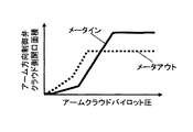
図6Aは、アーム方向制御弁23のアームクラウド側の開口特性を示す図であり、図6Bは、アームクラウド調速方向制御弁22のアームクラウド側の開口特性を示す図である。
FIG. 6A is a diagram showing the opening characteristic of the arm
図6Aにおいて、アーム方向制御弁23は、アームクラウドパイロット圧の増加に対して、メータイン開口面積がメータアウトの開口面積よりも先に増加し始めるように構成されている。すなわち、メータイン開口が開き始めるときのパイロット圧は、メータアウト開口が開き始めるときのパイロット圧よりも小さく設定されている。一方、アームクラウド調速方向制御弁22は、アームクラウド調速パイロット圧に対して、メータアウトの開口面積がメータインの開口面積よりも先に増加し始めるように構成されている。すなわち、メータアウト開口が開き始めるときのパイロット圧は、メータイン開口が開き始めるときのパイロット圧よりも小さく設定されている。また、アーム方向制御弁23のメータアウト開口面積とアームクラウド調速方向制御弁22のメータアウト開口面積とを比較した場合、アームクラウド調速方向制御弁22のメータアウトの開口面積の方が先に増加し始めるように構成されている。すなわち、アームクラウド調速方向制御弁22のメータイン開口が開き始めるときのパイロット圧は、アーム方向制御弁23のメータアウト開口が開き始めるときのパイロット圧よりも小さく設定されている。このように設定することで、パイロット圧が低い領域、すなわちアーム速度が低い領域では、アームクラウド調速方向制御弁22と並列に接続されているアーム方向制御弁23のメータアウト開口面積がゼロとなるため、アーム方向制御弁23によるメータアウト制御を不能としつつ、アームシリンダ6からの戻り流量をアームクラウド調速方向制御弁22のみによって調節することができる。これにより、掘削負荷の増大に応じてアームクラウド調速パイロット圧を減少補正することにより、掘削負荷が急激に低下したときに、アームシリンダ6の背圧が上昇し、アームシリンダ6に供給される圧油の流量が抑制され、アーム12の急加速が防止される。
In FIG. 6A, the arm
以上のように構成した本実施例において得られる効果を従来技術と比較して説明する。 The effects obtained in the present embodiment configured as described above will be described in comparison with the prior art.
図7Aは、従来技術に係る油圧ショベルによる掘削動作を示す図であり、図7Bは、本実施例に係る油圧ショベル300による掘削動作を示す図である。
FIG. 7A is a diagram showing an excavation operation by the hydraulic excavator according to the related art, and FIG. 7B is a diagram showing an excavation operation by the
図7Aにおいて、バケット8先端を目標軌跡に沿って移動している最中に目標軌跡よりも大きく突出した隆起部Pに突き当たると、ブームボトム圧に対するアームボトム圧の偏差(掘削負荷)の増大に応じて、アーム方向制御弁23のメータイン開口が拡大するようにアーム方向制御弁23の操作量が増加補正される。これにより、掘削負荷が増大した状態でもアームシリンダ6とブームシリンダ5の速度バランスが保たれ、バケット8先端を目標軌跡に沿って移動させることができる。しかし、バケット8先端が隆起部Pを通過した直後に掘削負荷が急激に低下し、アーム方向制御弁23のメータイン開口を介してアームシリンダ6のボトム側に多量の圧油が供給され、アーム12(図1に示す)がクラウド方向に急加速するおそれがある。その結果、バケット8先端が目標軌跡から大きく外れ、バケット8先端の進行方向と目標軌跡とが交差していた場合は、目標軌跡よりも深く掘削することになる。
In FIG. 7A, when the tip end of the bucket 8 hits a raised portion P protruding more than the target locus while moving along the target locus, the deviation of the arm bottom pressure from the boom bottom pressure (excavation load) increases. Accordingly, the operation amount of the arm
一方、本実施例に係る油圧ショベル300によれば、ブームボトム圧に対するアームボトム圧の偏差(掘削負荷)の増大に応じてアーム方向制御弁23の操作量が増加補正されたときに、アームクラウド調速方向制御弁33のメータアウト開口が絞られる。これにより、掘削負荷が増大した状態でのアームシリンダ6とブームシリンダ5の速度バランスが保たれると共に、掘削負荷が急激に低下したときに、アームシリンダ6の背圧が上昇し、アームシリンダ6に供給される圧油の流量が抑制される。その結果、図7Bに示すように、バケット8先端が隆起部Pを通過した直後にアーム12の急加速が防止されるため、バケット8先端が目標軌跡から大きく外れることを防止することができる。
On the other hand, according to the
以上のように構成した本実施例によれば、2ポンプ式の油圧ショベル300において、掘削負荷が急激に低下したときのアーム12の急加速を防止することにより、水平均し作業や法面整形作業等における仕上げ精度を向上させることができる。
According to the present embodiment configured as described above, in the two-pump
図8は、本発明の第2の実施例に係る油圧ショベルに搭載された油圧駆動装置の概略構成図である。以下、第1の実施例との相違点を中心に説明する。 FIG. 8 is a schematic configuration diagram of a hydraulic drive system mounted on a hydraulic excavator according to a second embodiment of the present invention. Hereinafter, differences from the first embodiment will be mainly described.
図8において、本実施例に係る油圧駆動装置400Aは、ブームボトム圧センサ5b(図2に示す)に代えて、第1ブーム方向制御弁21が配置されている第1ポンプラインL1に取り付けられた第1ポンプ吐出圧センサ2cを備え、アームボトム圧センサ6b(図2に示す)に代えて、アーム方向制御弁23が配置されている第2ポンプラインL2に取り付けられた第2ポンプ吐出圧センサ2dを備えている。
In FIG. 8, the
ポンプ吐出圧センサ2c,2dの圧力信号は、メインコントローラ100に入力される。第1油圧ポンプ2aの吐出圧はブームボトム圧に連動して変化し、第2油圧ポンプ2bの吐出圧はアームボトム圧に連動して変化する。そのため、メインコントローラ100は、ブームボトム圧を第1油圧ポンプ2aの吐出圧で代用し、アームボトム圧を第2油圧ポンプ2bの吐出圧で代用することができる。すなわち、第1ポンプ吐出圧センサ2cはブーム負荷圧検出装置を構成し、第2ポンプ吐出圧センサ2dはアーム負荷圧検出装置を構成している。
The pressure signals of the pump discharge pressure sensors 2c and 2d are input to the
以上のように構成した本実施例においても、第1の実施例と同様の効果が得られる。 Also in the present embodiment configured as described above, the same effect as in the first embodiment can be obtained.
また、本実施例におけるブーム負荷圧検出装置2cおよびアーム負荷圧検出装置2dは、油圧ポンプ2a,2bと同じく上部旋回体10の機械室に配置されるため、第1の実施例におけるブーム負荷圧検出装置5bおよびアーム負荷圧検出装置6b(図2に示す)よりも容易に取り付けることができる。
Further, since the boom load pressure detecting device 2c and the arm load pressure detecting device 2d in the present embodiment are arranged in the machine room of the
また、本実施例におけるブーム負荷圧検出装置2cおよびアーム負荷圧検出装置2dの設置環境は、第1の実施例におけるブーム負荷圧検出装置5bおよびアーム負荷圧検出装置6b(図2に示す)ほど過酷ではないため、ブーム負荷圧検出装置2cおよびアーム負荷圧検出装置2dの使用寿命を第1の実施例よりも伸ばすことができる。
Further, the installation environment of the boom load pressure detecting device 2c and the arm load pressure detecting device 2d in the present embodiment is the same as that of the boom load pressure detecting device 5b and the arm load
図9は、本発明の第3の実施例に係る油圧ショベルに搭載された油圧駆動装置の概略構成図である。以下、第1の実施例との相違点を中心に説明する。 FIG. 9 is a schematic configuration diagram of a hydraulic drive system mounted on a hydraulic excavator according to a third embodiment of the present invention. Hereinafter, differences from the first embodiment will be mainly described.
図9において、油圧駆動装置400Bは1ポンプ式の油圧駆動装置であり、第1の実施例における油圧駆動装置400から、第2油圧ポンプ2b、第2ブーム方向制御弁24、アームクラウド調速方向制御弁22および、それらに付随する第2ポンプラインL2、パラレル回路L2a、リリーフ弁27を取り除き、アーム方向制御弁23のメータアウト側と作動油16とを接続する油路にアーム調速弁装置としてのアームクラウド調速開閉弁25を設けた構成となっている。
In FIG. 9, the hydraulic drive device 400B is a one-pump hydraulic drive device, and includes the hydraulic drive device 400 of the first embodiment, the second
コントロールバルブ20Aにおいて、第1ポンプラインL1にはブーム方向制御弁21とアーム方向制御弁23が接続されており、第1油圧ポンプ2aが吐出する圧油は、ブームシリンダ5とアームシリンダ6に供給される。第1ブーム方向制御弁21とアーム方向制御弁23は、第1油圧ポンプ2aに対してパラレルに接続されており、分流可能に構成されている。
In the
図10Aは、アーム方向制御弁23Aのアームクラウド側の開口特性を示す図であり、図10Bは、アームクラウド調速開閉弁25の開口特性を示す図である。
FIG. 10A is a diagram showing the opening characteristic of the arm
図10Aにおいて、アーム方向制御弁23は、アームクラウドパイロット圧の増加に対して、メータアウト開口面積がメータインの開口面積よりも先に増加し始めるように構成されている。すなわち、メータアウト開口が開き始めるときのパイロット圧は、メータイン開口が開き始めるときのパイロット圧よりも小さく設定されている。また、アーム方向制御弁23のメータアウト開口面積とアームクラウド調速開閉弁25の開口面積とを比較した場合、アームクラウド調速開閉弁25の開口面積の方が遅れて増加し始めるように構成されている。すなわち、アームクラウド調速開閉弁25が開き始めるときのパイロット圧は、アーム方向制御弁23のメータイン開口が開き始めるときのパイロット圧よりも大きく設定されている。このように設定することで、パイロット圧が低い領域、すなわちアーム速度が低い領域では、アーム方向制御弁23と直列に接続されているアームクラウド調速開閉弁25の開口面積がアーム方向制御弁23のメータアウト開口面積よりも小さくなるため、アーム方向制御弁23によるメータアウト制御を不能としつつ、アームシリンダ6からの戻り流量をアームクラウド調速開閉弁25のみによって調節することができる。これにより、掘削負荷の増大に応じてアームクラウド調速パイロット圧を減少補正することにより、掘削負荷が急激に低下したときに、アームシリンダ6の背圧が上昇し、アームシリンダ6に供給される圧油の流量が抑制され、アーム12の急加速が防止される。
In FIG. 10A, the arm
以上のように構成した本実施例によれば、1ポンプ式の油圧ショベルにおいて、掘削負荷が急激に低下したときのアーム12の急加速を防止することにより、水平均し作業や法面整形作業等における仕上げ精度を向上させることができる。
According to the present embodiment configured as described above, in the one-pump hydraulic excavator, the water averaging work and the slope shaping work are performed by preventing the rapid acceleration of the
また、バケット8先端が目標面から離れるに従って、アームクラウド調速開閉弁25の開口の縮小幅が小さくなるため、アームクラウド調速開閉弁25の絞りによる圧力損失を低減することができる。
Further, as the tip end of the bucket 8 moves away from the target surface, the reduction width of the opening of the arm cloud speed control on/off
以上、本発明の実施例について詳述したが、本発明は、上記した実施例に限定されるものではなく、様々な変形例が含まれる。例えば、上記した実施例は、本発明を分かり易く説明するために詳細に説明したものであり、必ずしも説明した全ての構成を備えるものに限定されるものではない。また、ある実施例の構成に他の実施例の構成の一部を加えることも可能であり、ある実施例の構成の一部を削除し、あるいは、他の実施例の一部と置き換えることも可能である。 Although the embodiments of the present invention have been described in detail above, the present invention is not limited to the above-mentioned embodiments and includes various modifications. For example, the above-described embodiments have been described in detail in order to explain the present invention in an easy-to-understand manner, and are not necessarily limited to those having all the configurations described. Further, it is possible to add a part of the configuration of another embodiment to the configuration of a certain embodiment, delete a part of the configuration of a certain embodiment, or replace it with a part of another embodiment. It is possible.
1a…走行用右操作レバー装置、1b…走行用左操作レバー装置、1c…右操作レバー装置(ブーム操作装置)、1d…左操作レバー装置(アーム操作装置)、2…油圧ポンプ装置、2a…第1油圧ポンプ、2b…第2油圧ポンプ、2c…第1ポンプ吐出圧センサ(ブーム負荷圧検出装置)、2d…第2ポンプ吐出圧センサ(アーム負荷圧検出装置)、3…走行油圧モータ、4…旋回油圧モータ、5…ブームシリンダ、5b…ブームボトム圧センサ(ブーム負荷圧検出装置)、6…アームシリンダ、6b…アームボトム圧センサ(アーム負荷圧検出装置)、7…バケットシリンダ、8…バケット、9…下部走行体、10…上部旋回体、11…ブーム、12…アーム、13a…ブーム角度検出器、13b…アーム角度検出器、13c…バケット角度検出器、14…エンジン、15…作業装置、16…作動油タンク、20…コントロールバルブ、21…第1ブーム方向制御弁、21a,21b…電磁比例弁、22…アームクラウド調速方向制御弁(第2アーム方向制御弁、アーム調速弁装置)、22a…電磁比例弁、23,23A…アーム方向制御弁(第1アーム方向制御弁)、23a,23b…電磁比例弁、24…第2ブーム方向制御弁、25…アームクラウド調速開閉弁(アーム調速弁装置)、26…リリーフ弁、27…リリーフ弁、29…パイロット油圧源、32…モード設定スイッチ、100…メインコントローラ(制御装置)、110…目標パイロット圧演算部、120…作業装置位置取得部、130…目標面距離取得部、140…メインスプール制御部、141a〜141d…電磁弁駆動信号生成器、142a,142c…選択器、143…ブーム上げ補正パイロット圧演算器、144…最大値選択器、145…アームクラウド補正パイロット圧ゲイン演算器、146…乗算器、147…アームクラウド分流補正パイロット圧ゲイン演算器、148…減算器、150…アームクラウド調速制御部、151…電磁弁駆動信号生成器、152…選択器、154…パイロット圧上限値演算器、156…パイロット圧下限値演算器、157…最大値選択器、158…最小値選択器、200…情報コントローラ、300…油圧ショベル、400,400A,400B…油圧駆動装置、L1…第1ポンプライン、L1a…パラレル回路、L2…第2ポンプライン、L2a…パラレル回路、P…隆起部。
1a... right operating lever device for traveling, 1b... left operating lever device for traveling, 1c... right operating lever device (boom operating device), 1d... left operating lever device (arm operating device), 2... hydraulic pump device, 2a... 1st hydraulic pump, 2b... 2nd hydraulic pump, 2c... 1st pump discharge pressure sensor (boom load pressure detection device), 2d... 2nd pump discharge pressure sensor (arm load pressure detection device), 3... traveling hydraulic motor, 4... Swing hydraulic motor, 5... Boom cylinder, 5b... Boom bottom pressure sensor (boom load pressure detection device), 6... Arm cylinder, 6b... Arm bottom pressure sensor (arm load pressure detection device), 7... Bucket cylinder, 8 ...Bucket, 9...lower traveling body, 10...upper rotating body, 11...boom, 12...arm, 13a...boom angle detector, 13b...arm angle detector, 13c...bucket angle detector, 14...engine, 15... Work device, 16... Hydraulic oil tank, 20... Control valve, 21... First boom directional control valve, 21a, 21b... Electromagnetic proportional valve, 22... Arm cloud speed control directional control valve (second arm directional control valve, arm control Speed valve device), 22a... Electromagnetic proportional valve, 23, 23A... Arm directional control valve (first arm directional control valve), 23a, 23b... Electromagnetic proportional valve, 24... Second boom directional control valve, 25... Arm cloud adjustment Fast on-off valve (arm speed regulating valve device), 26... Relief valve, 27... Relief valve, 29... Pilot hydraulic pressure source, 32... Mode setting switch, 100... Main controller (control device), 110... Target pilot pressure calculation unit, 120... Work device position acquisition unit, 130... Target surface distance acquisition unit, 140... Main spool control unit, 141a to 141d... Electromagnetic valve drive signal generators, 142a, 142c... Selector, 143... Boom raising correction
Claims (4)
前記ブームを駆動するブームシリンダと、
前記アームを駆動するアームシリンダと、
作動油タンクと、
第1油圧ポンプと、
前記第1油圧ポンプから前記ブームシリンダに供給される圧油の流量と方向を制御する第1ブーム方向制御弁と、
前記第1油圧ポンプから前記アームシリンダに供給される圧油の流量と方向を制御する第1アーム方向制御弁と、
前記第1ブーム方向制御弁の操作量を指示するブーム操作装置と、
前記第1アーム方向制御弁の操作量を指示するアーム操作装置と、
前記ブームシリンダの負荷圧を検出するブーム負荷圧検出装置と、
前記アームシリンダの負荷圧を検出するアーム負荷圧検出装置と、
前記ブームシリンダの負荷圧に対する前記アームシリンダの負荷圧の偏差の増大に応じて前記アームシリンダのメータイン開口が拡大するように、前記アーム操作装置によって指示された前記第1アーム方向制御弁の操作量を増加補正する制御装置とを備えた油圧式作業機械において、
前記第1アーム方向制御弁とは独立して前記アームシリンダのメータアウト開口を調節できるアーム調速弁装置を更に備え、
前記制御装置は、前記アーム操作装置によって指示された操作量を増加補正するときに、前記アームシリンダの負荷圧の増大に応じて前記アームシリンダのメータアウト開口が縮小するように前記アーム調速弁装置を制御する
ことを特徴とする油圧式作業機械。 A work device having a boom and an arm,
A boom cylinder for driving the boom,
An arm cylinder for driving the arm,
Hydraulic oil tank,
A first hydraulic pump,
A first boom direction control valve for controlling the flow rate and direction of the pressure oil supplied from the first hydraulic pump to the boom cylinder;
A first arm direction control valve for controlling the flow rate and direction of pressure oil supplied from the first hydraulic pump to the arm cylinder;
A boom operation device for instructing an operation amount of the first boom direction control valve,
An arm operation device for instructing an operation amount of the first arm directional control valve,
A boom load pressure detection device for detecting the load pressure of the boom cylinder,
An arm load pressure detecting device for detecting a load pressure of the arm cylinder,
The operation amount of the first arm directional control valve instructed by the arm operation device so that the meter-in opening of the arm cylinder expands in accordance with an increase in the deviation of the load pressure of the arm cylinder from the load pressure of the boom cylinder. In a hydraulic work machine equipped with a control device for increasing and
Further comprising an arm speed control valve device capable of adjusting a meter-out opening of the arm cylinder independently of the first arm directional control valve,
The control device, when increasing and correcting the operation amount instructed by the arm operating device, causes the meter-out opening of the arm cylinder to decrease in accordance with an increase in the load pressure of the arm cylinder. A hydraulic work machine characterized by controlling the device.
第2油圧ポンプと、
前記ブーム操作装置によって指示された操作量に応じて、前記第2油圧ポンプから前記ブームシリンダに供給される圧油の流量と方向を制御する第2ブーム方向制御弁とを更に備え、
前記アーム調速弁装置は、前記アーム操作装置によって指示された操作量に応じて、前記第2油圧ポンプから前記アームシリンダに供給される圧油の流量と方向を制御する第2アーム方向制御弁であり、前記第2アーム方向制御弁は、前記第1アーム方向制御弁のメータアウト開口が開き始めるときの操作量よりも小さい操作量でメータアウト開口が開き始めるように構成されており、
前記制御装置は、前記アーム操作装置によって指示された操作量を増加補正するときに、前記アームシリンダの負荷圧の増大に応じて前記第2アーム方向制御弁の操作量を減少補正する
ことを特徴とする油圧式作業機械。 The hydraulic work machine according to claim 1,
A second hydraulic pump,
A second boom direction control valve for controlling a flow rate and a direction of the pressure oil supplied from the second hydraulic pump to the boom cylinder according to an operation amount instructed by the boom operation device,
The arm speed control valve device controls a flow rate and a direction of the pressure oil supplied from the second hydraulic pump to the arm cylinder according to an operation amount instructed by the arm operation device. The second arm directional control valve is configured such that the meter-out opening starts to open with a smaller operation amount than the operation amount when the meter-out opening of the first arm directional control valve starts to open.
When the operation amount instructed by the arm operation device is increased and corrected, the control device decreases and corrects the operation amount of the second arm directional control valve according to the increase of the load pressure of the arm cylinder. And hydraulic working machine.
前記アーム調速弁装置は、前記第1アーム方向制御弁と前記作動油タンクとを接続する油路に設けられた開閉弁である
ことを特徴とする油圧式作業機械。 The hydraulic work machine according to claim 1,
The hydraulic work machine, wherein the arm speed control valve device is an opening/closing valve provided in an oil passage connecting the first arm directional control valve and the hydraulic oil tank.
前記制御装置は、前記作業装置と施工目標面との距離である目標面距離を演算し、前記アーム操作装置によって指示された操作量を増加補正するときに、前記目標面距離の増大に応じて、前記アームシリンダの負荷圧の増大に応じた前記アームシリンダのメータアウト開口の縮小幅が小さくなるように前記アーム調速弁装置を制御する
ことを特徴とする油圧式作業機械。 The hydraulic work machine according to claim 1,
The control device calculates a target surface distance which is a distance between the work device and the construction target surface, and when the operation amount instructed by the arm operation device is increased and corrected, the controller responds to the increase in the target surface distance. The hydraulic work machine is characterized in that the arm speed control valve device is controlled so that a reduction width of a meter-out opening of the arm cylinder in accordance with an increase in a load pressure of the arm cylinder is reduced.
Priority Applications (6)
| Application Number | Priority Date | Filing Date | Title |
|---|---|---|---|
| JP2017161634A JP6707064B2 (en) | 2017-08-24 | 2017-08-24 | Hydraulic work machine |
| EP18848556.9A EP3575502B1 (en) | 2017-08-24 | 2018-08-09 | Hydraulic working machine |
| PCT/JP2018/029861 WO2019039294A1 (en) | 2017-08-24 | 2018-08-09 | Hydraulic working machine |
| CN201880014566.6A CN110392755B (en) | 2017-08-24 | 2018-08-09 | Hydraulic working machine |
| US16/490,203 US10801524B2 (en) | 2017-08-24 | 2018-08-09 | Hydraulic work machine |
| KR1020197025070A KR102248499B1 (en) | 2017-08-24 | 2018-08-09 | Hydraulic working machine |
Applications Claiming Priority (1)
| Application Number | Priority Date | Filing Date | Title |
|---|---|---|---|
| JP2017161634A JP6707064B2 (en) | 2017-08-24 | 2017-08-24 | Hydraulic work machine |
Publications (2)
| Publication Number | Publication Date |
|---|---|
| JP2019039208A JP2019039208A (en) | 2019-03-14 |
| JP6707064B2 true JP6707064B2 (en) | 2020-06-10 |
Family
ID=65438867
Family Applications (1)
| Application Number | Title | Priority Date | Filing Date |
|---|---|---|---|
| JP2017161634A Active JP6707064B2 (en) | 2017-08-24 | 2017-08-24 | Hydraulic work machine |
Country Status (6)
| Country | Link |
|---|---|
| US (1) | US10801524B2 (en) |
| EP (1) | EP3575502B1 (en) |
| JP (1) | JP6707064B2 (en) |
| KR (1) | KR102248499B1 (en) |
| CN (1) | CN110392755B (en) |
| WO (1) | WO2019039294A1 (en) |
Families Citing this family (10)
| Publication number | Priority date | Publication date | Assignee | Title |
|---|---|---|---|---|
| EP3666983A1 (en) * | 2018-12-12 | 2020-06-17 | Metalogenia Research & Technologies S.L. | Force measuring system for earth moving machinery |
| JP7253949B2 (en) * | 2019-03-25 | 2023-04-07 | 株式会社小松製作所 | Work machines, systems and methods of controlling work machines |
| JP7253478B2 (en) * | 2019-09-25 | 2023-04-06 | 日立建機株式会社 | working machine |
| JP2021095775A (en) * | 2019-12-18 | 2021-06-24 | 株式会社神戸製鋼所 | Work auxiliary device of work machine, and construction surface recognition method in work site |
| CN111102253A (en) * | 2019-12-25 | 2020-05-05 | 长沙中达智能科技有限公司 | Device and method for controlling speed of hydraulic driving mechanism |
| JP7473337B2 (en) * | 2019-12-27 | 2024-04-23 | 株式会社小松製作所 | CONTROL SYSTEM FOR WORK MACHINE, CONTROL MACHINE, AND CONTROL METHOD FOR WORK MACHINE |
| JP7324717B2 (en) * | 2020-01-14 | 2023-08-10 | キャタピラー エス エー アール エル | hydraulic control system |
| JP7530312B2 (en) * | 2021-02-12 | 2024-08-07 | 川崎重工業株式会社 | Multi-Control Valve |
| JP2022154940A (en) * | 2021-03-30 | 2022-10-13 | 株式会社小松製作所 | Hydraulic system of hydraulic shovel, hydraulic shovel, and control method of hydraulic shovel |
| CN119301328A (en) * | 2022-06-03 | 2025-01-10 | 奥菲克斯有限责任公司 | Valve device for mobile working machines with hydraulic loads |
Family Cites Families (21)
| Publication number | Priority date | Publication date | Assignee | Title |
|---|---|---|---|---|
| JPS61191728A (en) * | 1985-02-21 | 1986-08-26 | Hitachi Constr Mach Co Ltd | Controller for locus of excavation by oil-pressure shovel |
| JP2835866B2 (en) * | 1990-03-23 | 1998-12-14 | 日立建機株式会社 | Motor control device for hydraulically driven vehicle |
| JP2948065B2 (en) * | 1993-09-06 | 1999-09-13 | 日立建機株式会社 | Hydraulic drive for construction machinery |
| JP3500201B2 (en) * | 1994-10-31 | 2004-02-23 | 日立建機株式会社 | Hydraulic drive |
| JP3571142B2 (en) * | 1996-04-26 | 2004-09-29 | 日立建機株式会社 | Trajectory control device for construction machinery |
| JP3306301B2 (en) * | 1996-06-26 | 2002-07-24 | 日立建機株式会社 | Front control device for construction machinery |
| US5941155A (en) | 1996-11-20 | 1999-08-24 | Kabushiki Kaisha Kobe Seiko Sho | Hydraulic motor control system |
| JP3535701B2 (en) * | 1997-07-14 | 2004-06-07 | コベルコ建機株式会社 | Control device for hydraulic motor |
| JP4028090B2 (en) * | 1998-06-18 | 2007-12-26 | コベルコ建機株式会社 | Hydraulic controller for work machine |
| JP3935659B2 (en) * | 2000-05-19 | 2007-06-27 | 日立建機株式会社 | Hydraulic drive unit for construction machinery |
| US6502393B1 (en) * | 2000-09-08 | 2003-01-07 | Husco International, Inc. | Hydraulic system with cross function regeneration |
| US6467264B1 (en) * | 2001-05-02 | 2002-10-22 | Husco International, Inc. | Hydraulic circuit with a return line metering valve and method of operation |
| US7162869B2 (en) * | 2003-10-23 | 2007-01-16 | Caterpillar Inc | Hydraulic system for a work machine |
| JP5647052B2 (en) * | 2011-03-25 | 2014-12-24 | 日立建機株式会社 | Hybrid construction machine |
| JP5563096B2 (en) * | 2012-05-18 | 2014-07-30 | 憲平 山路 | Hydraulic control system |
| EP2943691B1 (en) * | 2012-12-14 | 2021-11-17 | Danfoss Power Solutions II Technology A/S | Online sensor calibration for electrohydraulic valves |
| KR102014547B1 (en) * | 2013-03-21 | 2019-08-26 | 두산인프라코어 주식회사 | Control system and method of Hydraulic Pump for Construction Machinery |
| JP6324347B2 (en) * | 2015-06-01 | 2018-05-16 | 日立建機株式会社 | Hydraulic control equipment for construction machinery |
| JP6545609B2 (en) * | 2015-12-04 | 2019-07-17 | 日立建機株式会社 | Control device of hydraulic construction machine |
| JP6474718B2 (en) * | 2015-12-25 | 2019-02-27 | 日立建機株式会社 | Hydraulic control equipment for construction machinery |
| JP6495857B2 (en) * | 2016-03-31 | 2019-04-03 | 日立建機株式会社 | Construction machinery |
-
2017
- 2017-08-24 JP JP2017161634A patent/JP6707064B2/en active Active
-
2018
- 2018-08-09 US US16/490,203 patent/US10801524B2/en active Active
- 2018-08-09 KR KR1020197025070A patent/KR102248499B1/en active IP Right Grant
- 2018-08-09 EP EP18848556.9A patent/EP3575502B1/en active Active
- 2018-08-09 WO PCT/JP2018/029861 patent/WO2019039294A1/en unknown
- 2018-08-09 CN CN201880014566.6A patent/CN110392755B/en active Active
Also Published As
| Publication number | Publication date |
|---|---|
| JP2019039208A (en) | 2019-03-14 |
| EP3575502B1 (en) | 2021-12-01 |
| US10801524B2 (en) | 2020-10-13 |
| CN110392755B (en) | 2021-10-22 |
| CN110392755A (en) | 2019-10-29 |
| KR102248499B1 (en) | 2021-05-06 |
| EP3575502A1 (en) | 2019-12-04 |
| KR20190112065A (en) | 2019-10-02 |
| EP3575502A4 (en) | 2020-12-02 |
| US20200011030A1 (en) | 2020-01-09 |
| WO2019039294A1 (en) | 2019-02-28 |
Similar Documents
| Publication | Publication Date | Title |
|---|---|---|
| JP6707064B2 (en) | Hydraulic work machine | |
| KR102110887B1 (en) | Construction machinery | |
| US6230090B1 (en) | Interference prevention system for two-piece boom type hydraulic excavator | |
| US9951797B2 (en) | Work machine | |
| US11466435B2 (en) | Hydraulic excavator with area limiting control function | |
| JP6474908B2 (en) | Hydraulic system of work machine | |
| JP6633464B2 (en) | Work machine | |
| JP6474718B2 (en) | Hydraulic control equipment for construction machinery | |
| US10227997B2 (en) | Hydraulic drive system for work machine | |
| JP6807290B2 (en) | Work machine | |
| JP6915042B2 (en) | Excavator | |
| WO2017094822A1 (en) | Control device for hydraulic construction machinery | |
| JP2015197185A (en) | Hydraulic control device or work machine | |
| KR102137127B1 (en) | Construction machinery | |
| JP6989548B2 (en) | Construction machinery | |
| JP7455285B2 (en) | construction machinery | |
| JP2013249900A (en) | Hydraulic drive circuit | |
| JP2004183277A (en) | Pump controller for construction machinery |
Legal Events
| Date | Code | Title | Description |
|---|---|---|---|
| A621 | Written request for application examination |
Free format text: JAPANESE INTERMEDIATE CODE: A621 Effective date: 20190815 |
|
| TRDD | Decision of grant or rejection written | ||
| A01 | Written decision to grant a patent or to grant a registration (utility model) |
Free format text: JAPANESE INTERMEDIATE CODE: A01 Effective date: 20200428 |
|
| A61 | First payment of annual fees (during grant procedure) |
Free format text: JAPANESE INTERMEDIATE CODE: A61 Effective date: 20200519 |
|
| R150 | Certificate of patent or registration of utility model |
Ref document number: 6707064 Country of ref document: JP Free format text: JAPANESE INTERMEDIATE CODE: R150 |