[go: up one dir, main page]

JP7378645B2 - Winding nozzle and winding machine - Google Patents

Winding nozzle and winding machine Download PDF

Info

Publication number
JP7378645B2
JP7378645B2 JP2022569416A JP2022569416A JP7378645B2 JP 7378645 B2 JP7378645 B2 JP 7378645B2 JP 2022569416 A JP2022569416 A JP 2022569416A JP 2022569416 A JP2022569416 A JP 2022569416A JP 7378645 B2 JP7378645 B2 JP 7378645B2
Authority
JP
Japan
Prior art keywords
winding
nozzle
wire
wound
tip
Prior art date
Legal status (The legal status is an assumption and is not a legal conclusion. Google has not performed a legal analysis and makes no representation as to the accuracy of the status listed.)
Active
Application number
JP2022569416A
Other languages
Japanese (ja)
Other versions
JPWO2022130557A1 (en
Inventor
計憲 足達
雄哉 横手
裕史 庄子
義和 藤末
Current Assignee (The listed assignees may be inaccurate. Google has not performed a legal analysis and makes no representation or warranty as to the accuracy of the list.)
Mitsubishi Electric Corp
Original Assignee
Mitsubishi Electric Corp
Priority date (The priority date is an assumption and is not a legal conclusion. Google has not performed a legal analysis and makes no representation as to the accuracy of the date listed.)
Filing date
Publication date
Application filed by Mitsubishi Electric Corp filed Critical Mitsubishi Electric Corp
Publication of JPWO2022130557A1 publication Critical patent/JPWO2022130557A1/ja
Application granted granted Critical
Publication of JP7378645B2 publication Critical patent/JP7378645B2/en
Active legal-status Critical Current
Anticipated expiration legal-status Critical

Links

Images

Classifications

    • HELECTRICITY
    • H02GENERATION; CONVERSION OR DISTRIBUTION OF ELECTRIC POWER
    • H02KDYNAMO-ELECTRIC MACHINES
    • H02K15/00Processes or apparatus specially adapted for manufacturing, assembling, maintaining or repairing of dynamo-electric machines
    • H02K15/08Forming windings by laying conductors into or around core parts
    • H02K15/095Forming windings by laying conductors into or around core parts by laying conductors around salient poles

Landscapes

  • Engineering & Computer Science (AREA)
  • Manufacturing & Machinery (AREA)
  • Power Engineering (AREA)
  • Manufacture Of Motors, Generators (AREA)

Description

本開示は、コイルを製造するための巻線ノズル及び巻線機に関し、特に巻線を繰り出すノズルの形状に関する。 The present disclosure relates to a winding nozzle and a winding machine for manufacturing a coil, and particularly relates to the shape of a nozzle for feeding out a winding wire.

従来、電動機の固定子等に用いられるコイルは、固定子を構成する鉄心に巻線を巻き付けることで製造される。コイルの製造には、巻線機が使用される。巻線機は、巻線を供給するノズルと、ノズルを保持するノズル保持部とを有している。巻線機において、鉄心に巻線を巻き付ける際には、水平方向に移動するノズル保持部に取り付けられたノズルから巻線が繰り出されて、鉄心に巻線が巻き回されていく。巻線機は、鉄心を中心として鉄心の周囲をノズルの先端が周回するようにノズルを移動させて、鉄心に巻線を巻き付けてコイルを形成する。 Conventionally, coils used in stators of electric motors and the like are manufactured by winding wires around an iron core that constitutes the stator. A winding machine is used to manufacture the coil. The winding machine has a nozzle that supplies winding wire and a nozzle holding section that holds the nozzle. In a winding machine, when a winding wire is wound around an iron core, the winding wire is fed out from a nozzle attached to a nozzle holding part that moves in a horizontal direction, and the winding wire is wound around the iron core. The winding machine moves a nozzle around the iron core so that the tip of the nozzle goes around the iron core, and winds the winding wire around the iron core to form a coil.

ノズルは例えば円柱形状を有し、ノズル保持部に固定される固定側端面と、巻線が引き出される側の先端面とを有している。また、ノズルは、固定側端面から先端面にわたって巻線が通るように形成された巻線通し部を有している(例えば、特許文献1参照)。 The nozzle has, for example, a cylindrical shape, and has a fixed end surface fixed to the nozzle holding part and a tip end surface from which the winding is drawn out. Further, the nozzle has a winding passage portion formed so that the winding wire passes from the fixed end face to the tip face (for example, see Patent Document 1).

特許文献1に記載の1つの実施形態に係る巻線通し部は、ノズル本体の側面に溝形状に形成された巻線挿通溝である。電線挿通溝は、固定側端面から先端面までノズルの軸方向に沿って延びている。 The winding wire passing portion according to one embodiment described in Patent Document 1 is a winding wire passing groove formed in a groove shape on the side surface of the nozzle body. The wire insertion groove extends along the axial direction of the nozzle from the fixed side end surface to the tip surface.

巻線通し部が溝形状の場合、巻線機が固定子に対して巻線を行っている間は、巻線が常時引っ張られている状態であるため、巻線が巻線挿通溝から外れることはない。しかしながら、巻線機が一時停止して再起動したときに、巻線が巻線挿通孔から外れることがある。また、固定子の鉄心には、絶縁性を有するインシュレータが設けられている。インシュレータには、固定子のティース間を繋ぐ渡り配線が固定されたり、あるいは、端子等が配置される。巻線通し部が溝形状の場合、インシュレータに巻線を絡げる際、又は、ティース間に渡り配線を渡す際に、巻線が巻線挿通孔から外れることがある。巻線が巻線挿通孔から外れた場合、巻線動作を継続することはできないため、いったん、巻線機を停止させて、作業員が巻線を巻線挿通孔に挿入し直す必要があった。 If the winding passage part is groove-shaped, the winding is constantly being pulled while the winding machine is winding the stator, so the winding may come off the winding passage groove. Never. However, when the winding machine is temporarily stopped and restarted, the winding may come off from the winding insertion hole. Further, the iron core of the stator is provided with an insulator having insulation properties. A crossover wiring that connects the teeth of the stator is fixed to the insulator, or a terminal or the like is arranged on the insulator. When the winding passage portion is in the form of a groove, the winding may come off from the winding insertion hole when winding the winding around the insulator or passing the wiring between the teeth. If the winding comes off the winding insertion hole, winding operation cannot be continued, so the winding machine must be stopped and the worker must reinsert the winding into the winding insertion hole. Ta.

そのため、特許文献1では、巻線通し部が、固定側端面から先端面まで貫通する貫通孔形状の巻線挿通孔から構成されている実施形態も提案している。いずれの実施形態においても、巻線は、ノズルの固定側端面から巻線通し部に挿入され、巻線通し部を通って、先端面から引き出される。 Therefore, Patent Document 1 also proposes an embodiment in which the winding wire passing portion is constituted by a winding wire passing hole in the form of a through hole penetrating from the fixed side end face to the tip end face. In either embodiment, the winding is inserted into the winding passage from the fixed end face of the nozzle, passes through the winding passage, and is pulled out from the tip face.

国際公開第2020/065853号International Publication No. 2020/065853

特許文献1に開示されているノズルは、上述したように、巻線が通るように形成された巻線通し部を有している。また、巻線通し部は、上述したように、溝形状、又は、貫通孔形状に形成されている。 As described above, the nozzle disclosed in Patent Document 1 has a winding passage portion formed through which the winding wire passes. Further, as described above, the winding wire passing portion is formed in the shape of a groove or a through hole.

巻線通し部が溝形状の場合、巻線機の再起動時、インシュレータへの巻線の絡げ動作時、あるいは、ティース間の渡り線形成時に、巻線がノズルから外れてしまうという課題があった。 If the winding passage part is groove-shaped, there is a problem that the winding may come off from the nozzle when restarting the winding machine, winding the winding around the insulator, or forming the crossover wire between the teeth. there were.

一方、巻線通し部が貫通孔形状の場合、巻線がノズルから外れることはない。しかしながら、巻線通し部が貫通孔形状の場合、溝形状の場合と比較して、巻線を巻線挿通孔に挿入する際の巻線の曲げ角度が大きくなる。そのため、巻線が巻線挿通孔にスムーズに挿入されず、巻線に大きな引っ張り負荷がかかる。すなわち、巻線機での巻線動作時に、巻線が強く引っ張られ、巻線の伸び率が上昇してしまうという課題があった。巻線の伸び率が上昇した場合、巻線から構成されたコイルの電気抵抗が増加し、ひいては、電動機の負荷が増加してしまっていた。 On the other hand, when the winding passage portion has a through-hole shape, the winding does not come off from the nozzle. However, when the winding wire passing portion has a through-hole shape, the bending angle of the winding wire when inserting the winding wire into the winding wire insertion hole becomes larger than when the winding wire passing portion has a groove shape. Therefore, the winding is not smoothly inserted into the winding insertion hole, and a large tensile load is applied to the winding. That is, there is a problem in that the winding wire is strongly pulled during the winding operation in the winding machine, resulting in an increase in the elongation rate of the winding wire. When the elongation rate of the winding increases, the electrical resistance of the coil made up of the winding increases, which in turn increases the load on the motor.

また、特許文献1では、ノズルの先端面がR形状を有しており、引き出された巻線は当該R形状に沿って曲げられる。R形状が大きい場合、巻線に無理な力が加わらないため、巻線の伸び率が上昇しない。そのため、特許文献1では、巻線通し部が貫通孔形状の場合に、R形状を大きくする目的で、巻線挿通孔をノズルの中心軸からずれた位置に形成している。その結果、巻線挿通孔が設けられている側のノズルの内壁が薄肉となり、強度不足となり、強いテンションでの巻線には不向きであった。 Further, in Patent Document 1, the tip surface of the nozzle has an R shape, and the drawn-out winding wire is bent along the R shape. When the R shape is large, no excessive force is applied to the winding, so the elongation rate of the winding does not increase. Therefore, in Patent Document 1, when the winding through hole is in the shape of a through hole, the winding through hole is formed at a position offset from the central axis of the nozzle in order to increase the R shape. As a result, the inner wall of the nozzle on the side where the winding wire insertion hole is provided becomes thin and has insufficient strength, making it unsuitable for winding wire under strong tension.

本開示は、かかる課題を解決するためになされたものであり、巻線機での巻線動作中又は他の動作中に巻線がノズルから外れることを防止し、また、ノズルの強度を確保し、さらに、巻線の伸び率の低減を図ることが可能な、巻線ノズル及び巻線機を提供することを目的とする。 The present disclosure has been made in order to solve such problems, and prevents the winding from coming off the nozzle during the winding operation of the winding machine or other operations, and also ensures the strength of the nozzle. A further object of the present invention is to provide a winding nozzle and a winding machine that can reduce the elongation rate of the winding wire.

本開示に係る巻線ノズルは、鉄心に巻線を巻き付けてコイルを形成する巻線機で用いられ、柱状の外形形状を有し、先端面から前記巻線が引き出され、前記鉄心の周囲を移動して、前記巻線を前記鉄心に巻き付ける巻線ノズルであって、前記巻線機のノズル保持部に取り付けられる固定側端面である第1端面と、前記巻線が引き出される前記先端面である第2端面と、前記第1端面から前記第2端面にわたって巻線が通るように、前記第1端面から前記第2端面まで前記巻線ノズルの長手方向に延びた巻線通し部と、前記巻線通し部と連通して前記第2端面に溝状に形成された先端溝部とを備え、前記先端溝部は、前記第2端面において、前記巻線ノズルの外周を構成する第1側面から前記巻線ノズルの外周を構成し前記第1側面に対向する第2側面まで延設され、前記巻線通し部は、前記巻線ノズルの長手方向に延びる中心軸に対して前記第1端面側から前記第2端面側に向かうに従って前記第2側面側から前記第1側面側に延びるように傾斜して配置され、前記巻線通し部の前記中心軸に対して傾斜する方向は、前記先端溝部の延設方向と反対方向である。 The winding nozzle according to the present disclosure is used in a winding machine that winds a winding wire around an iron core to form a coil, and has a columnar outer shape, and the winding wire is pulled out from the tip surface and surrounds the iron core. A winding nozzle that moves to wind the winding wire around the iron core, the winding nozzle having a first end surface that is a fixed side end surface that is attached to a nozzle holding part of the winding machine, and the tip surface from which the winding wire is pulled out. a winding wire passing portion extending in the longitudinal direction of the winding nozzle from the first end face to the second end face so that the winding wire passes from the first end face to the second end face; a tip groove formed in a groove shape on the second end face in communication with the winding passage portion; It extends to a second side surface that constitutes the outer periphery of the winding nozzle and is opposite to the first side surface, and the winding passage portion extends from the first end surface side with respect to the central axis extending in the longitudinal direction of the winding nozzle. The winding wire passing portion is arranged to be inclined so as to extend from the second side surface side to the first side surface side as it goes toward the second end surface side, and the direction of the winding passage portion is inclined with respect to the central axis of the winding passage portion. This is the opposite direction to the extension direction.

本開示に係る巻線機は、少なくとも1つの上記の巻線ノズルと、前記巻線ノズルを保持するノズル保持部と、前記ノズル保持部を水平方向に移動させる駆動ユニットとを備えたものである。 A winding machine according to the present disclosure includes at least one of the above winding nozzles, a nozzle holding part that holds the winding nozzle, and a drive unit that moves the nozzle holding part in a horizontal direction. .

本開示に係る巻線ノズル及び巻線機によれば、巻線機での巻線動作中又は他の動作中に巻線がノズルから外れることを防止し、また、ノズルの強度を確保し、さらに、巻線の伸び率の低減を図ることができる。 According to the winding nozzle and winding machine according to the present disclosure, the winding can be prevented from coming off the nozzle during the winding operation or other operations in the winding machine, and the strength of the nozzle can be ensured. Furthermore, it is possible to reduce the elongation rate of the winding.

実施の形態1に係る巻線機100の全体構造を示す模式図である。1 is a schematic diagram showing the overall structure of a winding machine 100 according to Embodiment 1. FIG. 電動機等に使用される固定子10の構造の一例を示す平面図である。FIG. 1 is a plan view showing an example of the structure of a stator 10 used in an electric motor or the like. 図2に示した固定子10の側面図である。3 is a side view of the stator 10 shown in FIG. 2. FIG. 固定子10が実装された状態の一例を示す図である。FIG. 3 is a diagram showing an example of a state in which a stator 10 is mounted. 実施の形態1に係る巻線機100により鉄心1にコイル2を形成する際の巻線ノズル50を示す斜視図である。FIG. 2 is a perspective view showing a winding nozzle 50 when forming a coil 2 on the iron core 1 using the winding machine 100 according to the first embodiment. 図5の平面図である。FIG. 6 is a plan view of FIG. 5; 実施の形態1に係る巻線機100により鉄心1に渡り線3Aを渡す際の巻線ノズル50の動きを示す平面図である。FIG. 3 is a plan view showing the movement of the winding nozzle 50 when the wire winding machine 100 according to the first embodiment passes the crossover wire 3A to the iron core 1; 実施の形態1に係る巻線機100の巻線ノズル50の斜視図である。1 is a perspective view of a winding nozzle 50 of a winding machine 100 according to Embodiment 1. FIG. 実施の形態1に係る巻線機100の巻線ノズル50の斜視図である。1 is a perspective view of a winding nozzle 50 of a winding machine 100 according to Embodiment 1. FIG. 実施の形態1に係る巻線機100の巻線ノズル50の先端面56を示す部分拡大斜視図である。FIG. 3 is a partially enlarged perspective view showing a tip end surface 56 of the winding nozzle 50 of the winding machine 100 according to the first embodiment. 実施の形態1に係る巻線機100の巻線ノズル50の構成を示す(a)断面図及び(b)側面図である。1A is a cross-sectional view and FIG. 3B is a side view showing the configuration of a winding nozzle 50 of a winding machine 100 according to Embodiment 1. FIG. 実施の形態1に係る巻線機100の巻線ノズル50に巻線3を通した状態を示す説明図である。FIG. 3 is an explanatory diagram showing a state in which the winding 3 is passed through the winding nozzle 50 of the winding machine 100 according to the first embodiment. 実施の形態1に係る巻線機100の巻線ノズル50に巻線3を通した状態を示す説明図である。FIG. 3 is an explanatory diagram showing a state in which the winding 3 is passed through the winding nozzle 50 of the winding machine 100 according to the first embodiment. 実施の形態1に係る巻線機100において鉄心1のティース1aに巻線3を巻き付けている状態の模式図である。FIG. 3 is a schematic diagram showing a state in which the winding 3 is wound around the teeth 1a of the iron core 1 in the winding machine 100 according to the first embodiment. 実施の形態1に係る巻線機100によりコイル2が形成された鉄心1の断面構造の説明図である。FIG. 2 is an explanatory diagram of a cross-sectional structure of an iron core 1 in which a coil 2 is formed by a winding machine 100 according to the first embodiment. 実施の形態1に係る巻線機100の巻線ノズル50の比較例として、特許文献1に記載の巻線ノズル150の構成を示す説明図である。FIG. 2 is an explanatory diagram showing a configuration of a winding nozzle 150 described in Patent Document 1 as a comparative example of the winding nozzle 50 of the winding machine 100 according to the first embodiment. 図16の比較例の巻線ノズル150に通した状態の巻線3を模式的に示す説明図である。17 is an explanatory diagram schematically showing the winding 3 passed through the winding nozzle 150 of the comparative example of FIG. 16. FIG. 図16の比較例の巻線ノズル150に通した状態の巻線3を模式的に示す説明図である。17 is an explanatory diagram schematically showing the winding 3 passed through the winding nozzle 150 of the comparative example of FIG. 16. FIG. 曲率半径と曲線の緩急との関係を示す説明図である。It is an explanatory view showing the relationship between the radius of curvature and the steepness and steepness of a curve.

以下、本開示に係る巻線ノズル及び巻線機の実施の形態について図面を参照して説明する。本開示は、以下の実施の形態に限定されるものではなく、本開示の主旨を逸脱しない範囲で種々に変形することが可能である。また、本開示は、以下の実施の形態およびその変形例に示す構成のうち、組み合わせ可能な構成のあらゆる組み合わせを含むものである。また、各図において、同一の符号を付したものは、同一の又はこれに相当するものであり、これは明細書の全文において共通している。なお、各図面では、各構成部材の相対的な寸法関係または形状等が実際のものとは異なる場合がある。 Hereinafter, embodiments of a winding nozzle and a winding machine according to the present disclosure will be described with reference to the drawings. The present disclosure is not limited to the following embodiments, and can be variously modified without departing from the gist of the present disclosure. Furthermore, the present disclosure includes all combinations of configurations that can be combined among the configurations shown in the following embodiments and modifications thereof. Furthermore, in each figure, the same reference numerals are the same or equivalent, and this is common throughout the entire specification. Note that in each drawing, the relative dimensional relationship or shape of each component may differ from the actual one.

実施の形態1.
図1は、実施の形態1に係る巻線機100の全体構造を示す模式図である。図2は、電動機等に使用される固定子10の構造の一例を示す平面図である。図3は、図2に示した固定子10の側面図である。図3は、固定子10を構成する1つの鉄心1の側面を示している。巻線機100は、例えば電動機20(図4参照)の固定子10を構成するコイル2を形成するための装置である。巻線機100は、固定子10を構成する鉄心1に巻線3を巻き付けることでコイル2を形成する。
Embodiment 1.
FIG. 1 is a schematic diagram showing the overall structure of a winding machine 100 according to the first embodiment. FIG. 2 is a plan view showing an example of the structure of a stator 10 used in an electric motor or the like. FIG. 3 is a side view of the stator 10 shown in FIG. 2. FIG. 3 shows a side view of one iron core 1 constituting the stator 10. As shown in FIG. The winding machine 100 is a device for forming, for example, a coil 2 that constitutes a stator 10 of an electric motor 20 (see FIG. 4). The winding machine 100 forms the coil 2 by winding the winding 3 around the iron core 1 that constitutes the stator 10 .

図1に示すように、鉄心1は、ティース1aとスロット面1bとを有している。但し、図1においては、鉄心1は模式的に表してあり、鉄心1は図1に示す形状に限定されるものではない。図2に示されるように、固定子10は、複数個の鉄心1を円環状に並べて形成される。鉄心1の個数は、任意の個数でよく、電動機20の仕様及び用途等により適宜決定される。各鉄心1は、図3に示すように、U側インシュレータ4及びL側インシュレータ5を備えている。U側インシュレータ4及びL側インシュレータ5は、鉄心1に一体に成形されるか、又は、別途成形されたものを鉄心1に取り付けて構成される。U側インシュレータ4及びL側インシュレータ5は、絶縁部材から構成されており、絶縁性を有している。U側インシュレータ4及びL側インシュレータ5には、各コイル2間を繋ぐ渡り線3A(図7参照)が固定され、又は、端子(図示せず)等が配置される。 As shown in FIG. 1, the iron core 1 has teeth 1a and slot surfaces 1b. However, in FIG. 1, the iron core 1 is schematically shown, and the iron core 1 is not limited to the shape shown in FIG. As shown in FIG. 2, the stator 10 is formed by arranging a plurality of iron cores 1 in an annular shape. The number of iron cores 1 may be any number, and is appropriately determined depending on the specifications and usage of the electric motor 20. Each core 1 includes a U-side insulator 4 and an L-side insulator 5, as shown in FIG. The U-side insulator 4 and the L-side insulator 5 are formed integrally with the iron core 1, or are formed separately and attached to the iron core 1. The U-side insulator 4 and the L-side insulator 5 are made of an insulating member and have insulation properties. A crossover wire 3A (see FIG. 7) connecting each coil 2 is fixed to the U-side insulator 4 and the L-side insulator 5, or a terminal (not shown) or the like is arranged thereon.

固定子10は、次のようにして形成される。まず、後述する図5に示すように、鉄心1を直線状に複数接続した状態で、巻線機100により、各鉄心1のスロット面1bに巻線3が巻き付けられて、コイル2が形成される。各鉄心1のスロット面1bにコイル2が形成された後に、直線状に接続した複数の鉄心1を円環状にし、複数接続された鉄心1のうち両端に位置する鉄心1同士を溶接等により接合することにより、図2に示す円環状の固定子10が形成される。 Stator 10 is formed as follows. First, as shown in FIG. 5, which will be described later, with a plurality of iron cores 1 connected in a straight line, the winding machine 100 winds the winding 3 around the slot surface 1b of each iron core 1 to form the coil 2. Ru. After the coil 2 is formed on the slot surface 1b of each core 1, the plurality of linearly connected cores 1 are formed into an annular shape, and the cores 1 located at both ends of the plurality of connected cores 1 are joined by welding or the like. By doing so, the annular stator 10 shown in FIG. 2 is formed.

図4は、固定子10が実装された状態の一例を示す図である。固定子10は、例えば電動機20に内蔵される。電動機20は、固定子10と回転子11とから構成されている。固定子10は、上述したように、複数の鉄心1が円環状に並べられて形成されているため、各鉄心1の内周側には、筒状部が形成されている。回転子11は、固定子10の筒状部に配置される。回転子11は、円柱形状を有し、回転軸12に固定されている。回転子11は、回転軸12が回転されることにより、回転駆動される。図4は、電動機20が、空調機(図示せず)の室外ユニットなどに用いられる圧縮機200に搭載された例を示している。電動機20は、圧縮機200の筐体200a内に配置されている。筐体200aの下部には、圧縮機構200bが設けられている。圧縮機構200bは、圧縮機200の吸入口200cから吸入された冷媒を圧縮して、圧縮機200の吐出口200dから圧縮した冷媒を吐出する。圧縮機構200bは、電動機20により駆動される。電動機20は、固定子10に接続された配線からコイル2に電力が供給され、コイル2と鉄心1とにより発生する磁界により回転子11を回転駆動する。 FIG. 4 is a diagram showing an example of a state in which the stator 10 is mounted. The stator 10 is built into, for example, an electric motor 20. The electric motor 20 is composed of a stator 10 and a rotor 11. As described above, the stator 10 is formed by arranging a plurality of iron cores 1 in an annular shape, so that a cylindrical portion is formed on the inner peripheral side of each iron core 1. The rotor 11 is arranged in the cylindrical part of the stator 10. The rotor 11 has a cylindrical shape and is fixed to the rotating shaft 12. The rotor 11 is rotationally driven by the rotation of the rotating shaft 12. FIG. 4 shows an example in which the electric motor 20 is mounted on a compressor 200 used in an outdoor unit of an air conditioner (not shown). The electric motor 20 is arranged within a housing 200a of the compressor 200. A compression mechanism 200b is provided at the bottom of the housing 200a. The compression mechanism 200b compresses the refrigerant sucked in from the suction port 200c of the compressor 200, and discharges the compressed refrigerant from the discharge port 200d of the compressor 200. Compression mechanism 200b is driven by electric motor 20. In the electric motor 20 , power is supplied to the coil 2 from wiring connected to the stator 10 , and the rotor 11 is rotationally driven by a magnetic field generated by the coil 2 and the iron core 1 .

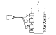
図1に示すように、巻線機100は、巻線ノズル50が取り付けられたノズル保持部61と、ノズル保持部61を水平方向に移動させる駆動ユニット60と、巻線3を案内する1対の滑車62とを備えている。さらに、巻線機100は、巻線3の張力を調整するテンショナ部63と、巻線3が蓄えられている巻線ボビン64とを備えている。 As shown in FIG. 1, the winding machine 100 includes a nozzle holding section 61 to which a winding nozzle 50 is attached, a drive unit 60 that moves the nozzle holding section 61 in the horizontal direction, and a pair of drive units that guide the winding 3. A pulley 62 is provided. Furthermore, the winding machine 100 includes a tensioner section 63 that adjusts the tension of the winding 3, and a winding bobbin 64 in which the winding 3 is stored.

ノズル保持部61は、駆動ユニット60により、矢印90で模式的に示されるように、図1のX方向及びZ方向に水平移動する。X方向は紙面の左右方向に対応した幅方向であり、Z方向は、X方向に直交する奥行き方向である。Y方向は、X方向及びZ方向に直交する垂直方向である。X方向及びZ方向は例えば水平方向であり、Y方向は例えば鉛直方向である。 The nozzle holding part 61 is horizontally moved in the X direction and the Z direction in FIG. 1 by the drive unit 60, as schematically shown by an arrow 90. The X direction is the width direction corresponding to the horizontal direction of the paper, and the Z direction is the depth direction orthogonal to the X direction. The Y direction is a vertical direction orthogonal to the X and Z directions. The X direction and the Z direction are, for example, the horizontal direction, and the Y direction is, for example, the vertical direction.

巻線3は、巻線ボビン64から引き出され、テンショナ部63を通って、1対の滑車62により案内され、ノズル保持部61内を通される。ノズル保持部61を通った巻線3は、ノズル保持部61によって保持されている巻線ノズル50を通って、巻線ノズル50の先端部から引き出される。巻線3の先端は、鉄心1に固定されており、巻線3は、ティース1aのスロット面1bに巻き付けられる。また、巻線機100は、制御装置80を備え、制御装置80は、少なくとも、駆動ユニット60、テンショナ部63、及び、巻線ノズル50を自転させる機構を制御する。 The winding 3 is pulled out from the winding bobbin 64, passes through the tensioner section 63, is guided by a pair of pulleys 62, and is passed through the nozzle holding section 61. The winding 3 that has passed through the nozzle holding part 61 passes through the winding nozzle 50 held by the nozzle holding part 61 and is drawn out from the tip of the winding nozzle 50 . The tip of the winding 3 is fixed to the iron core 1, and the winding 3 is wound around the slot surface 1b of the teeth 1a. Further, the winding machine 100 includes a control device 80, and the control device 80 controls at least the drive unit 60, the tensioner section 63, and a mechanism for rotating the winding nozzle 50.

ここで、制御装置80のハードウェア構成について説明する。制御装置80は処理回路から構成される。処理回路は、専用のハードウェア、または、プロセッサから構成される。専用のハードウェアは、例えば、ASIC(Application Specific Integrated Circuit)またはFPGA(Field Programmable Gate Array)などである。プロセッサは、メモリに記憶されるプログラムを実行する。制御装置80は、記憶部(図示せず)を有している。記憶部はメモリから構成される。メモリは、RAM(Random Access Memory)、ROM(Read Only Memory)、フラッシュメモリ、EPROM(Erasable Programmable ROM)などの不揮発性または揮発性の半導体メモリ、もしくは、磁気ディスク、フレキシブルディスク、光ディスクなどのディスクである。 Here, the hardware configuration of the control device 80 will be explained. The control device 80 is composed of a processing circuit. The processing circuitry consists of dedicated hardware or a processor. The dedicated hardware is, for example, an ASIC (Application Specific Integrated Circuit) or an FPGA (Field Programmable Gate Array). A processor executes programs stored in memory. The control device 80 has a storage section (not shown). The storage unit is composed of memory. Memory can be nonvolatile or volatile semiconductor memory such as RAM (Random Access Memory), ROM (Read Only Memory), flash memory, or EPROM (Erasable Programmable ROM), or disks such as magnetic disks, flexible disks, or optical disks. be.

図5は、実施の形態1に係る巻線機100により鉄心1にコイル2を形成する際の巻線ノズル50を示す斜視図である。図6は、図5の平面図である。実施の形態1においては、図5及び図6に示すように、固定子10の各鉄心1が直線状に並ぶように固定子10を展開した状態で、巻線3が各鉄心1に巻き付けられてコイル2が形成される。巻線ノズル50は、図5に示すように、円柱形状を有し、内部に巻線3が通る巻線通し部51が設けられている。実施の形態1においては、巻線機100に、3つの巻線ノズル50が設けられている。巻線機100は、図6に示すように、3つの巻線ノズル50を同時に動かして、右から1番目から3番目までの3つの鉄心1のティース1aのスロット面1bに同時に巻線3を巻き付ける。巻線ノズル50は、図5に示すように、巻線3が通される方向、つまり巻線ノズル50の軸方向を、固定子10を展開した面に対して直交させるように配置される。巻線ノズル50は、図6に示される軌跡tに沿って移動する。つまり、巻線ノズル50は、ティース1aの周りを略矩形を描くように移動し、ティース1aに巻線3を巻き付ける。また、巻線ノズル50は、図6の自転方向rの向きに、巻線ノズル50の中心軸Aを軸として自転可能に設置されている。なお、図6に示された軌跡tは、一例であり、その他の形状を描くようにティース1aの周りを巻線ノズル50が移動してもよい。また、自転方向rは、図6では反時計回りの例が示されているが、逆向き(すなわち、時計回り)であっても良い。 FIG. 5 is a perspective view showing the winding nozzle 50 when the coil 2 is formed on the iron core 1 by the winding machine 100 according to the first embodiment. FIG. 6 is a plan view of FIG. 5. In Embodiment 1, as shown in FIGS. 5 and 6, the winding 3 is wound around each core 1 with the stator 10 unfolded so that each core 1 of the stator 10 is lined up in a straight line. A coil 2 is formed. As shown in FIG. 5, the winding nozzle 50 has a cylindrical shape, and is provided with a winding passage portion 51 through which the winding 3 passes. In the first embodiment, the winding machine 100 is provided with three winding nozzles 50. As shown in FIG. 6, the winding machine 100 simultaneously moves the three winding nozzles 50 to simultaneously wind the winding 3 onto the slot surfaces 1b of the teeth 1a of the three iron cores 1 from the first to third from the right. Wrap it around. As shown in FIG. 5, the winding nozzle 50 is arranged so that the direction in which the winding 3 is passed, that is, the axial direction of the winding nozzle 50, is perpendicular to the plane in which the stator 10 is expanded. The winding nozzle 50 moves along a trajectory t shown in FIG. That is, the winding nozzle 50 moves around the teeth 1a so as to draw a substantially rectangular shape, and winds the winding 3 around the teeth 1a. Further, the winding nozzle 50 is installed so as to be able to rotate about the central axis A of the winding nozzle 50 in the direction of rotation r in FIG. 6 . Note that the trajectory t shown in FIG. 6 is an example, and the winding nozzle 50 may move around the teeth 1a so as to draw other shapes. Further, although the rotation direction r is shown as being counterclockwise in FIG. 6, it may be in the opposite direction (that is, clockwise).

図7は、実施の形態1に係る巻線機100により鉄心1に渡り線3Aを渡す際の巻線ノズル50の動きを示す平面図である。図5及び図6を用いて説明したように、実施の形態1では、巻線機100が、3つの鉄心1のティース1aに同時に巻線3を巻き付ける。すなわち、実施の形態1では、まず、図6に示すように、右から1番目から3番目までの3つの鉄心1のティース1aに同時に巻線3が巻き付けてコイル2を形成する。次に、図7に示すように、3つの巻線ノズル50の位置を移動させて、右から4番目から6番目までの3つの鉄心1のティース1aに同時に巻線3が巻き付けてコイル2を形成する。このように、巻線機100は、3つの鉄心1を1つのグループにして、図7の矢印D1の方向に、グループごとにコイル2を順に形成していく。このとき、1つのグループのコイル2が形成されて、次のグループのコイル2の形成に移行する際に、巻線3を切らずに、グループ間に渡り線3Aを渡して、次のグループのティース1aに巻線3を巻き付ける。このように、渡り線3Aとは、隣接する2つのグループのそれぞれに含まれるティース1a間に渡される巻線3のことである。図7の例では、右から1番目の鉄心1のティース1aから、右から4番目の鉄心1のティース1aに、渡り線3Aが渡されている。同様に、右から2番目の鉄心1のティース1aから、右から5番目の鉄心1のティース1aに、渡り線3Aが渡され、右から3番目の鉄心1のティース1aから、右から6番目の鉄心1のティース1aに、渡り線3Aが渡されている。 FIG. 7 is a plan view showing the movement of the winding nozzle 50 when the crossover wire 3A is passed to the iron core 1 by the winding machine 100 according to the first embodiment. As described using FIGS. 5 and 6, in the first embodiment, the winding machine 100 winds the windings 3 around the teeth 1a of the three iron cores 1 at the same time. That is, in the first embodiment, first, as shown in FIG. 6, the coil 2 is formed by simultaneously winding the winding 3 around the teeth 1a of the three iron cores 1 from the first to third from the right. Next, as shown in FIG. 7, the positions of the three winding nozzles 50 are moved so that the winding 3 is simultaneously wound around the teeth 1a of the three iron cores 1 from the fourth to the sixth from the right. Form. In this manner, the winding machine 100 forms the three cores 1 into one group and sequentially forms the coils 2 for each group in the direction of the arrow D1 in FIG. 7. At this time, when one group of coils 2 is formed and the next group of coils 2 is formed, the connecting wire 3A is passed between the groups without cutting the winding 3, and the next group of coils 2 is formed. Winding wire 3 is wound around teeth 1a. In this way, the crossover wire 3A refers to the winding 3 that is passed between the teeth 1a included in each of two adjacent groups. In the example of FIG. 7, the crossover wire 3A is passed from the teeth 1a of the first iron core 1 from the right to the teeth 1a of the fourth iron core 1 from the right. Similarly, the crossover wire 3A is passed from the tooth 1a of the second core 1 from the right to the tooth 1a of the fifth core 1 from the right, and from the tooth 1a of the third core 1 from the right to the tooth 1a of the sixth core 1 from the right. A crossover wire 3A is passed to the teeth 1a of the iron core 1.

図8及び図9は、実施の形態1に係る巻線機100の巻線ノズル50の斜視図である。図10は、実施の形態1に係る巻線機100の巻線ノズル50の先端面56を示す部分拡大斜視図である。図10は、図8及び図9の下側から先端面56を見た状態を示している。図10では、説明のため、図8及び図9に示す先端開放部70を破線で示している。図11は、実施の形態1に係る巻線機100の巻線ノズル50の構成を示す(a)断面図及び(b)側面図である。図11(b)は、先端面56を示している。以下、図8~図11を用いて、巻線ノズル50の構成について説明する。 8 and 9 are perspective views of the winding nozzle 50 of the winding machine 100 according to the first embodiment. FIG. 10 is a partially enlarged perspective view showing the tip surface 56 of the winding nozzle 50 of the winding machine 100 according to the first embodiment. FIG. 10 shows the distal end surface 56 viewed from below in FIGS. 8 and 9. In FIG. 10, for explanation, the open end portion 70 shown in FIGS. 8 and 9 is shown with a broken line. FIG. 11 is a cross-sectional view (a) and a side view (b) showing the configuration of the winding nozzle 50 of the winding machine 100 according to the first embodiment. FIG. 11(b) shows the tip surface 56. The configuration of the wire-wound nozzle 50 will be described below with reference to FIGS. 8 to 11.

図8~図11に示すように、実施の形態1において、巻線ノズル50は、円柱形状を有している。巻線ノズル50には、図11(a)に示すように、巻線3を通すための巻線通し部51が設けられている。巻線通し部51は、貫通孔形状を有する貫通孔部71と、外部に対して開口して開放状態に形成された先端開放部70とから構成されている。 As shown in FIGS. 8 to 11, in the first embodiment, the wire-wound nozzle 50 has a cylindrical shape. As shown in FIG. 11(a), the winding nozzle 50 is provided with a winding passing portion 51 through which the winding 3 is passed. The winding wire passing portion 51 includes a through hole portion 71 having a through hole shape, and an open end portion 70 that is open to the outside and formed in an open state.

巻線ノズル50の一端は、図1に示した巻線機100のノズル保持部61に固定される固定側端面55(第1端面)である。巻線3は、固定側端面55に設けられた巻線挿入口55aから巻線通し部51内に挿入される。また、巻線ノズル50の他端は、先端面56(第2端面)である。巻線通し部51を通った巻線3は、先端面56の巻線供給部56aから引き出されてティース1aへの巻線動作に使用される。なお、巻線ノズル50の形状は、円柱形状だけに限定されるものではなく、固定側端面55から先端面56に亘って巻線3が通される構造であれば、その他の形状を取っても良い。すなわち、巻線ノズル50は、例えば、楕円形を底面とする楕円柱形状、又は、多角形を底面とする多角柱形状などであってもよい。 One end of the winding nozzle 50 is a fixed side end surface 55 (first end surface) fixed to the nozzle holding part 61 of the winding machine 100 shown in FIG. The winding 3 is inserted into the winding passage portion 51 through a winding insertion opening 55a provided on the fixed end face 55. Further, the other end of the winding nozzle 50 is a tip surface 56 (second end surface). The winding 3 that has passed through the winding passing portion 51 is pulled out from the winding supply portion 56a of the tip face 56 and used for winding the teeth 1a. Note that the shape of the winding nozzle 50 is not limited to only a cylindrical shape, but may take other shapes as long as it has a structure in which the winding 3 is passed from the fixed side end face 55 to the tip face 56. Also good. That is, the winding nozzle 50 may be, for example, in the shape of an elliptical column having an elliptical bottom surface, or in the shape of a polygonal column having a polygonal bottom surface.

図1に示した巻線機100は、巻線ノズル50の固定側端面55をノズル保持部61で保持して固定する。また、巻線機100は、巻線ノズル50の固定側端面55から先端面56に亘って巻線通し部51内に巻線3を通し、巻線ノズル50の先端面56の巻線供給部56aから巻線3を引き出す。そして、巻線機100は、図6に示したように、巻線ノズル50を鉄心1のティース1aの周りで移動させることにより、先端面56の巻線供給部56aから引き出された巻線3をティース1aに巻き付ける。 The winding machine 100 shown in FIG. 1 holds and fixes the fixed side end surface 55 of the winding nozzle 50 with a nozzle holding part 61. The winding machine 100 also passes the winding 3 through the winding passing portion 51 from the fixed side end surface 55 to the tip end surface 56 of the winding nozzle 50, and passes the winding wire 3 through the winding feeding section 51 of the tip end surface 56 of the winding nozzle 50. Winding 3 is pulled out from 56a. Then, as shown in FIG. 6, the winding machine 100 moves the winding nozzle 50 around the teeth 1a of the iron core 1, so that the winding 3 is pulled out from the winding supply part 56a of the tip surface 56. Wrap it around teeth 1a.

巻線ノズル50には、図11(a)に示すように、円柱形状の長手方向に延びた巻線通し部51が設けられている。巻線通し部51は、固定側端面55から先端面56にわたって巻線3が通るように、固定側端面55から先端面56まで巻線ノズル50の長手方向(軸方向)に向かって延びている。巻線通し部51は、貫通孔形状を有する貫通孔部71と、開放状態に形成された先端開放部70とを有している。貫通孔部71は、固定側端面55に設けられた巻線挿入口55aから、巻線ノズル50の側面50aに形成された先端開放部70までを貫通する貫通孔で構成されている。 As shown in FIG. 11(a), the winding nozzle 50 is provided with a winding passage portion 51 having a cylindrical shape and extending in the longitudinal direction. The winding passing portion 51 extends in the longitudinal direction (axial direction) of the winding nozzle 50 from the fixed end face 55 to the end face 56 so that the winding 3 passes from the fixed end face 55 to the end face 56. . The winding wire passing portion 51 has a through hole portion 71 having a through hole shape and an open end portion 70 formed in an open state. The through-hole portion 71 is configured as a through-hole that penetrates from the winding wire insertion port 55a provided on the fixed side end surface 55 to the tip opening portion 70 formed on the side surface 50a of the winding nozzle 50.

固定側端面55に設けられた巻線挿入口55aは、図8及び図11(a)に示すように、固定側端面55の中心部分に配置されている。すなわち、巻線挿入口55aは、図11(a)に示すように、巻線ノズル50の固定側端面55において、巻線ノズル50の中心軸A上に設けられている。なお、巻線挿入口55aは、必ずしも、巻線ノズル50の中心軸A上に配置されていなくてもよい。すなわち、巻線挿入口55aは、巻線ノズル50の中心軸Aから多少シフトされていてもよい。但し、その場合には、巻線通し部51の内壁面51aが薄肉とならない程度に、巻線挿入口55aを巻線ノズル50の中心軸Aからシフトさせる。 The winding wire insertion opening 55a provided in the fixed end face 55 is arranged at the center of the fixed end face 55, as shown in FIGS. 8 and 11(a). That is, the winding insertion port 55a is provided on the central axis A of the winding nozzle 50 at the fixed end surface 55 of the winding nozzle 50, as shown in FIG. 11(a). Note that the winding insertion port 55a does not necessarily have to be arranged on the central axis A of the winding nozzle 50. That is, the winding insertion port 55a may be shifted somewhat from the central axis A of the winding nozzle 50. However, in that case, the winding insertion opening 55a is shifted from the central axis A of the winding nozzle 50 to such an extent that the inner wall surface 51a of the winding passage portion 51 does not become thin.

以下では、説明のため、巻線ノズル50本体の外周を構成する側面50aのうち、図11(a)における上側の側面部分を「側面50a-1」と呼び、下側の側面部分を「側面50a-2」と呼ぶこととする。 Hereinafter, for the sake of explanation, among the side surfaces 50a constituting the outer periphery of the winding nozzle 50 main body, the upper side surface portion in FIG. 50a-2".

巻線通し部51の貫通孔部71は、図11(a)に示すように、巻線ノズル50の中心軸Aに対して傾斜して設けられている。さらに詳細に言えば、巻線通し部51の内壁面51aの長手方向は、巻線ノズル50の中心軸Aに対して、角度αだけ傾斜している。 The through hole portion 71 of the winding wire passing portion 51 is provided to be inclined with respect to the central axis A of the winding nozzle 50, as shown in FIG. 11(a). More specifically, the longitudinal direction of the inner wall surface 51a of the winding passage portion 51 is inclined at an angle α with respect to the central axis A of the winding nozzle 50.

巻線通し部51の貫通孔部71は、巻線挿入口55aから先端開放部70まで延設されている。貫通孔部71は、内壁面51aを有している。一方、先端開放部70は、図11(a)に示すように、巻線ノズル50の側面50a-2に形成されている。先端開放部70は、図8及び図9に示すように、矩形形状の開口部70aを有している。このように、巻線通し部51の先端面56側の端部は、先端開放部70になっている。先端開放部70は、巻線通し部51の内壁面51aが設けられておらず、外部に対して開放された状態となっている。 The through hole portion 71 of the winding passage portion 51 extends from the winding insertion opening 55 a to the open end portion 70 . The through hole portion 71 has an inner wall surface 51a. On the other hand, the open end portion 70 is formed on the side surface 50a-2 of the winding nozzle 50, as shown in FIG. 11(a). As shown in FIGS. 8 and 9, the open end portion 70 has a rectangular opening 70a. In this way, the end of the winding wire passing portion 51 on the tip surface 56 side forms the tip open portion 70. The open end portion 70 is not provided with the inner wall surface 51a of the winding passage portion 51, and is open to the outside.

巻線ノズル50の先端面56には、図11(a)に示すように、巻線供給部56aが設けられている。巻線供給部56aは、溝状に形成された先端溝部52と、巻線供給口53とを有している。先端溝部52は、先端面56に形成された溝である。先端溝部52は、側面50a-2(第1側面)から側面50a-1(第2側面)に向かって、巻線ノズル50の径方向に沿って延設されている。従って、先端溝部52の延設方向は、図11(b)の矢印D2の方向である。すなわち、図11(b)の紙面において、下から上に向かう方向である。先端溝部52の延設方向は、巻線ノズル50の中心軸Aに対して直交している。また、先端溝部52の延設方向の両端は、巻線ノズル50本体の側面50a-1及び50a-2において開口している。先端溝部52の側面50a-1側の端部は、巻線3が引き出される巻線供給口53になっている。なお、上述したように、巻線通し部51は、巻線ノズル50の中心軸Aに対して傾斜している。巻線通し部51の傾斜する方向は、図11(a)の矢印D3の方向である。すなわち、図11(b)の紙面において、上から下に向かう方向である。すなわち、巻線通し部51は、側面50a-1(第2側面)から側面50a-2(第1側面)に向かう方向に傾斜している。このように、巻線通し部51は、先端溝部52の延設方向と反対方向に傾斜している。 A winding supply section 56a is provided on the tip end surface 56 of the winding nozzle 50, as shown in FIG. 11(a). The winding supply section 56a has a groove-shaped distal end groove 52 and a winding supply port 53. The tip groove portion 52 is a groove formed in the tip surface 56. The tip groove portion 52 extends along the radial direction of the wire winding nozzle 50 from the side surface 50a-2 (first side surface) toward the side surface 50a-1 (second side surface). Therefore, the extending direction of the tip groove portion 52 is the direction of arrow D2 in FIG. 11(b). That is, in the paper of FIG. 11(b), the direction is from the bottom to the top. The extending direction of the tip groove portion 52 is perpendicular to the central axis A of the winding nozzle 50. Further, both ends of the tip groove portion 52 in the extending direction are open at side surfaces 50a-1 and 50a-2 of the main body of the winding nozzle 50. The end of the tip groove 52 on the side surface 50a-1 side is a winding supply port 53 from which the winding 3 is drawn out. Note that, as described above, the winding passage portion 51 is inclined with respect to the central axis A of the winding nozzle 50. The direction in which the winding passage portion 51 is inclined is the direction of arrow D3 in FIG. 11(a). That is, the direction is from top to bottom in the paper of FIG. 11(b). That is, the winding wire passing portion 51 is inclined in the direction from the side surface 50a-1 (second side surface) toward the side surface 50a-2 (first side surface). In this way, the winding passing portion 51 is inclined in the direction opposite to the direction in which the tip groove portion 52 extends.

巻線通し部51と先端溝部52とは、互いに連通している。つまり、巻線通し部51と先端溝部52とは接続されて1本の巻線3の通り道となるように形成されている。図11(a)に示すように、巻線通し部51の内壁面51aと先端溝部52の内壁面52aとが交わる部分である第1交差部57は、曲面から形成されており、内壁面51aと内壁面52aとを連続した面となるように接続している。実施の形態1において、第1交差部57は、図11(a)に示す断面において円弧形状になっているが、その他の曲線形状であっても良く、巻線3が接触したときに切断が生じないように滑らかな曲線で構成されることが望ましい。 The winding passage portion 51 and the tip groove portion 52 communicate with each other. In other words, the winding passing portion 51 and the tip groove portion 52 are connected to each other and are formed to provide a path for one winding 3. As shown in FIG. 11(a), the first intersection portion 57, which is the portion where the inner wall surface 51a of the winding wire passage portion 51 and the inner wall surface 52a of the tip groove portion 52 intersect, is formed from a curved surface, and the inner wall surface 51a and the inner wall surface 52a are connected to form a continuous surface. In the first embodiment, the first intersection portion 57 has an arc shape in the cross section shown in FIG. It is desirable to have a smooth curve to avoid this.

また、図11(b)に示すように、先端溝部52の内壁面52aと巻線ノズル50の側面50a-1とが交わる部分である第2交差部58は、曲面から形成されており、内壁面52aと側面50a-1とが連続した面となるように接続している。つまり、内壁面52aと側面50a-1とが交わって出来る稜線は、全て曲面で形成されている。実施の形態1において、第2交差部58は、図11(b)において円弧形状になっているが、その他の曲線形状であっても良く、巻線3が接触したときに切断が生じないように滑らかな曲線で構成されることが望ましい。 Further, as shown in FIG. 11(b), a second intersection portion 58, which is a portion where the inner wall surface 52a of the tip groove portion 52 and the side surface 50a-1 of the winding nozzle 50 intersect, is formed from a curved surface, and has an inner surface. The wall surface 52a and the side surface 50a-1 are connected to form a continuous surface. In other words, all of the ridge lines formed by the intersection of the inner wall surface 52a and the side surface 50a-1 are formed by curved surfaces. In the first embodiment, the second intersection 58 has an arc shape in FIG. It is desirable to have a smooth curve.

なお、図11(a)において、長さsは、第1交差部57から先端溝部52の巻線供給口53までの長さである。この長さsの部分を、以下では、部分Sと呼ぶ。部分Sの長さsが長いほど、巻線3は第1交差部57に沿って緩やかに曲がることができる。逆に、部分Sの長さsが短いほど、巻線3は第1交差部57に沿って急カーブで曲がることになる。この原理については、図19を用いて後述する。そのため、実施の形態1では、長さsを巻線ノズル50の径に対して出来るだけ長くするために、巻線通し部51の貫通孔部71を傾斜させ、且つ、巻線通し部51の先端に先端開放部70を設けている。先端開放部70は、巻線ノズル50の側面50a-2で開口している。当該構成により、長さsは、巻線ノズル50の径に対して最大限長くなっている。 Note that in FIG. 11A, the length s is the length from the first intersection 57 to the winding supply port 53 of the tip groove 52. This portion of length s is hereinafter referred to as portion S. The longer the length s of the portion S, the more gently the winding 3 can bend along the first intersection 57. Conversely, the shorter the length s of the portion S, the sharper the winding 3 will curve along the first intersection 57. This principle will be described later using FIG. 19. Therefore, in the first embodiment, in order to make the length s as long as possible with respect to the diameter of the winding nozzle 50, the through-hole portion 71 of the winding wire passing portion 51 is inclined, and the through hole portion 71 of the winding wire passing portion 51 is A tip open portion 70 is provided at the tip. The open end portion 70 opens at the side surface 50a-2 of the winding nozzle 50. With this configuration, the length s is as long as possible with respect to the diameter of the winding nozzle 50.

また、図11(a)に示されるように、巻線通し部51の内壁面51aと固定側端面55とが交わる第3交差部59は、曲面から形成されており、内壁面51aと固定側端面55とが連続した面となるように接続している。第3交差部59は、図11(a)の断面において円弧形状になっているが、その他の曲線形状であっても良く、巻線3が接触したときに切断が生じないように滑らかな曲線で構成されることが望ましい。 Further, as shown in FIG. 11(a), a third intersection portion 59 where the inner wall surface 51a of the winding wire passing portion 51 and the fixed side end surface 55 intersect is formed from a curved surface, and the third intersection portion 59 is formed from a curved surface. The end face 55 is connected to form a continuous surface. Although the third intersection 59 has an arc shape in the cross section shown in FIG. It is desirable that the

図12及び図13は、実施の形態1に係る巻線機100の巻線ノズル50に巻線3を通した状態を示す説明図である。図14は、実施の形態1に係る巻線機100において鉄心1のティース1aに巻線3を巻き付けている状態の模式図である。図12に示されるように、巻線ノズル50は、固定側端面55から先端面56わたって巻線3が通るように形成された巻線通し部51と、先端面56に溝状に形成された先端溝部52と、を備えている。巻線3は、巻線機100の各部を通して巻線ノズル50の固定側端面55から、巻線通し部51に入り、巻線通し部51に沿って、先端面56に至る。 12 and 13 are explanatory diagrams showing a state in which the winding 3 is passed through the winding nozzle 50 of the winding machine 100 according to the first embodiment. FIG. 14 is a schematic diagram of a state in which the winding 3 is wound around the teeth 1a of the iron core 1 in the winding machine 100 according to the first embodiment. As shown in FIG. 12, the winding nozzle 50 includes a winding passage portion 51 formed through which the winding 3 passes from a fixed side end surface 55 to a tip surface 56, and a groove formed in the tip surface 56. A tip groove portion 52 is provided. The winding 3 passes through each part of the winding machine 100 , enters the winding passage part 51 from the fixed end face 55 of the winding nozzle 50 , and reaches the tip face 56 along the winding passage part 51 .

先端面56に至った巻線3は、図12に示すように、巻線ノズル50の巻線通し部51と先端溝部52との交わった部分である第1交差部57の曲面に沿って、巻線ノズル50の側面50a-1側に曲げられる。側面50a-1は、先端開放部70が形成されている側面50a-2に対して反対側の面である。すなわち、側面50a-1と側面50a-2とは対向して配置されている。第1交差部57において、巻線通し部51の内壁面51aと先端溝部52の内壁面52aとが成す角度は、角度βである。角度βは、90°より小さい鋭角である。従って、第1交差部57において、巻線3は角度βだけ曲げられる。 As shown in FIG. 12, the winding 3 that has reached the tip face 56 is moved along the curved surface of the first intersection 57, which is the intersection of the winding passing portion 51 and the tip groove 52 of the winding nozzle 50. It is bent toward the side surface 50a-1 of the winding nozzle 50. The side surface 50a-1 is a surface opposite to the side surface 50a-2 where the open end portion 70 is formed. That is, the side surface 50a-1 and the side surface 50a-2 are arranged to face each other. In the first intersection portion 57, the angle formed by the inner wall surface 51a of the winding wire passage portion 51 and the inner wall surface 52a of the tip groove portion 52 is an angle β. The angle β is an acute angle less than 90°. Therefore, at the first intersection 57 the winding 3 is bent by an angle β.

第1交差部57の曲面に沿って側面50a-1側に向かって角度βだけ曲げられた巻線3は、図13に示すように、先端溝部52に沿って進む。その後、先端溝部52と巻線ノズル50の側面50aとが交わった部分である第2交差部58の曲面に沿って、巻線ノズル50の長手方向及び先端溝部52の延設方向に対し交差する方向に引き出される。先端溝部52の内壁面52aと、第2交差部58の曲面の接線とが成す角度は、角度γである。角度γは、例えば90°より大きい鈍角である。従って、第2交差部58において、巻線3は角度γだけ曲げられる。なお、角度γの大きさは特に限定されない。すなわち、角度γは、90°でもよく、あるいは、90°未満でもよい。 The winding 3 bent by an angle β toward the side surface 50a-1 along the curved surface of the first intersection 57 advances along the tip groove 52, as shown in FIG. Thereafter, along the curved surface of the second intersection 58, which is the intersection of the tip groove 52 and the side surface 50a of the winding nozzle 50, the line intersects with the longitudinal direction of the winding nozzle 50 and the extending direction of the tip groove 52. pulled in the direction. The angle between the inner wall surface 52a of the tip groove portion 52 and the tangent to the curved surface of the second intersection portion 58 is an angle γ. The angle γ is, for example, an obtuse angle greater than 90°. Therefore, at the second intersection 58 the winding 3 is bent by an angle γ. Note that the size of the angle γ is not particularly limited. That is, the angle γ may be 90° or less than 90°.

実施の形態1では、巻線通し部51を、巻線ノズル50の中心軸Aに対して傾斜させて配置している。これにより、巻線通し部51を傾斜させない場合と比較して、第1交差部57のR曲面形状が大きくなり、R曲面の半径Rが大きくなる。実施の形態1は、第1交差部57の半径R又は曲率が、巻線ノズル50の直径に対して最大限大きくできる構造である。このように、第1交差部57のR曲面形状が大きくなると、巻線3に無理な力が加わらず、巻線3の引っ張り負荷が小さくなるので、巻線3の伸び率が上昇することを防止することができる。 In the first embodiment, the winding passage portion 51 is arranged to be inclined with respect to the central axis A of the winding nozzle 50. As a result, the R-curved shape of the first intersection portion 57 becomes larger, and the radius R of the R-curved surface becomes larger, compared to the case where the winding passing portion 51 is not inclined. Embodiment 1 has a structure in which the radius R or curvature of the first intersection 57 can be made as large as possible with respect to the diameter of the winding nozzle 50. In this way, when the R curved shape of the first intersection portion 57 becomes larger, an unreasonable force is not applied to the winding 3 and the tensile load on the winding 3 becomes smaller, so that the elongation rate of the winding 3 increases. It can be prevented.

さらに、実施の形態1では、巻線通し部51の先端面56側の端部に、巻線ノズル50本体の側面50a-2で開口している先端開放部70を設けている。先端開放部70は、内壁面51aを有しておらず、外部に対して開放状態である。そのため、先端開放部70を通る巻線3の動きは、内壁面51aによって抑制されない。その結果、先端開放部70を通る巻線3には、無理な力が一切加わることがなく、巻線3が強く引っ張られないため、巻線3の伸び率の上昇をさらに防止することができる。 Furthermore, in the first embodiment, a tip open portion 70 that opens at the side surface 50a-2 of the winding nozzle 50 body is provided at the end of the winding wire passing portion 51 on the tip surface 56 side. The open end portion 70 does not have an inner wall surface 51a and is open to the outside. Therefore, the movement of the winding 3 passing through the open end portion 70 is not suppressed by the inner wall surface 51a. As a result, no unreasonable force is applied to the winding 3 passing through the open end portion 70, and the winding 3 is not pulled strongly, so that an increase in the elongation rate of the winding 3 can be further prevented. .

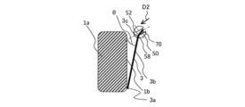
図14に示されるように、巻線ノズル50は、ティース1aの周囲を周回し、巻線3をスロット面1bに巻き付ける。ここで、巻線3のうち、スロット面1bに巻き付けられている部分を巻き付け部3aと呼び、巻き付け部3aから先端溝部52までの間に位置する部分を巻線引き出し部3bと呼ぶ。このとき、先端溝部52の矢印D2で示される延設方向は、巻線3の巻線引き出し部3bに対し、角度θを成すように向けられている。そのため、巻線3は、先端溝部52から引き出される部分で第2交差部58に沿って曲げられる。 As shown in FIG. 14, the winding nozzle 50 goes around the teeth 1a and winds the winding 3 around the slot surface 1b. Here, the part of the winding 3 that is wound around the slot surface 1b is called a winding part 3a, and the part located between the winding part 3a and the tip groove part 52 is called a winding pull-out part 3b. At this time, the extending direction of the tip groove portion 52 indicated by the arrow D2 is oriented at an angle θ with respect to the winding lead-out portion 3b of the winding wire 3. Therefore, the winding 3 is bent along the second intersection 58 at the portion pulled out from the tip groove 52.

巻線3は、巻線ノズル50の先端溝部52の巻線供給口53で、第2交差部58の曲面に押し付けられながら引き出される。これにより、巻線3は、第2交差部58の曲面により、ティース1aのスロット面1bに対して反りが生じる。つまり、巻線引き出し部3bは、スロット面1bに向かって凸になるように反りが生じている。巻線ノズル50は、先端溝部52と巻線引き出し部3bとの間の角度θを一定に維持したまま、ティース1aの周りを周回することが望ましい。そのため、制御装置80は、角度θが一定の値になるように、巻線ノズル50の水平方向位置及び自転角度を制御する。これにより、巻線ノズル50は、水平方向位置が変動するとともに、自転角度を角度θが一定となるように制御装置80により制御される。そのため、巻線3は、ティース1aに巻き付けられている間に常にスロット面1bに対して反るように力を受けながら巻き付けられている。 The winding 3 is pulled out while being pressed against the curved surface of the second intersection 58 at the winding supply port 53 of the tip groove 52 of the winding nozzle 50 . As a result, the winding 3 is warped with respect to the slot surface 1b of the teeth 1a due to the curved surface of the second intersection portion 58. In other words, the winding lead-out portion 3b is warped so as to be convex toward the slot surface 1b. It is desirable that the winding nozzle 50 revolves around the teeth 1a while keeping the angle θ between the tip groove portion 52 and the winding pull-out portion 3b constant. Therefore, the control device 80 controls the horizontal position and rotation angle of the winding nozzle 50 so that the angle θ becomes a constant value. Thereby, the winding nozzle 50 is controlled by the control device 80 so that the horizontal position changes and the rotation angle is kept constant at the angle θ. Therefore, while the winding 3 is being wound around the teeth 1a, the winding 3 is always being subjected to a force so as to be warped against the slot surface 1b.

図15は、実施の形態1に係る巻線機100によりコイル2が形成された鉄心1の断面構造の説明図である。図15において、矢印80は例えば図1のX方向を示し、矢印81は例えば図1のY方向を示す。図15に示された断面は、固定子10の鉄心1のうちの1つを、図2に示される図と平行な面で切断した場合の断面を示している。図14に示すように、巻線動作中の巻線3は、巻線ノズル50によって弓なりに反っており、その弓なりに反った頂点3cがスロット面1b側に向いている。一方、図15に示すように、巻線3は、スロット面1bに対して垂直方向に沿って延びているため、スロット面1bとコイル2の1層目との隙間wが低減され、さらに、2層目以降も隙間が低減されるため、コイル2が巻き締まる方向で巻かれる。このように、スロット面1bと巻線3との隙間w、及び、巻線3間の隙間が低減されると、その分だけ、スロット面1bに巻線3を多く巻けるので、巻線占積率が高くなり、電動機20の出力が大きくなるという利点がある。さらに、コイル2を形成する巻線3は、スロット面1bの方向に向かって凸になるように反りが生じているため、巻線3の剛性によりコイル2が巻き膨らむことを抑制することができる。 FIG. 15 is an explanatory diagram of the cross-sectional structure of the iron core 1 in which the coil 2 is formed by the winding machine 100 according to the first embodiment. In FIG. 15, an arrow 80 indicates, for example, the X direction in FIG. 1, and an arrow 81 indicates, for example, the Y direction in FIG. The cross section shown in FIG. 15 shows a cross section when one of the iron cores 1 of the stator 10 is cut along a plane parallel to the diagram shown in FIG. 2. As shown in FIG. 14, the winding 3 during the winding operation is arched by the winding nozzle 50, and the apex 3c of the arch is directed toward the slot surface 1b. On the other hand, as shown in FIG. 15, since the winding 3 extends perpendicularly to the slot surface 1b, the gap w between the slot surface 1b and the first layer of the coil 2 is reduced. Since the gap is reduced in the second and subsequent layers, the coil 2 is wound in the direction of tight winding. In this way, when the gap w between the slot surface 1b and the winding 3 and the gap between the windings 3 are reduced, more windings 3 can be wound on the slot surface 1b by that much, so the winding space is increased. This has the advantage that the rate becomes higher and the output of the electric motor 20 becomes larger. Furthermore, since the winding 3 forming the coil 2 is warped so as to be convex toward the slot surface 1b, the rigidity of the winding 3 can prevent the coil 2 from expanding. .

図16は、実施の形態1に係る巻線機100の巻線ノズル50の比較例として、特許文献1に記載の巻線ノズル150の構成を示す説明図である。図16(a)は、巻線ノズル150の固定側端面155を示す側面図であり、図16(c)は、巻線ノズル150の先端面156を示す側面図である。また、図16(b)は、巻線ノズル150の断面図である。図17及び図18は、図16の比較例の巻線ノズル150に通した状態の巻線3を模式的に示す説明図である。 FIG. 16 is an explanatory diagram showing the configuration of a winding nozzle 150 described in Patent Document 1 as a comparative example of the winding nozzle 50 of the winding machine 100 according to the first embodiment. 16(a) is a side view showing the fixed side end surface 155 of the wire winding nozzle 150, and FIG. 16(c) is a side view showing the tip end surface 156 of the wire winding nozzle 150. Further, FIG. 16(b) is a cross-sectional view of the wire-wound nozzle 150. 17 and 18 are explanatory diagrams schematically showing the winding 3 passed through the winding nozzle 150 of the comparative example of FIG. 16.

図16~図18は、比較例の巻線ノズル150の巻線通し部151が貫通孔から構成されている場合を示している。巻線通し部151は、固定側端面155から先端面156まで延びた貫通孔である。巻線通し部151は、先端面156に形成された先端溝部152と連通している。巻線通し部151は、円柱形状の巻線ノズル150の中心軸Aと平行に配置されている。ただし、巻線通し部151は、図16(b)に示すように、中心軸A上には配置されておらず、中心軸Aからシフトされた位置に配置されている。その理由は、図17に示す長さsを長くすることで、その部分の曲率半径Rを大きくするためである。以下では、その部分を「部分S」と呼ぶ。曲率半径Rが大きくなると、部分Sの長さsが長くなり、部分Sを形成する曲線がなだらかになる。この原理について、図19を用いて以下に説明する。図19は、曲率半径と曲線の緩急との関係を示す説明図である。 16 to 18 show a case where the winding passage portion 151 of the winding nozzle 150 of the comparative example is constituted by a through hole. The winding passing portion 151 is a through hole extending from the fixed side end surface 155 to the distal end surface 156. The winding passage portion 151 communicates with a tip groove portion 152 formed on the tip surface 156. The winding passage portion 151 is arranged parallel to the central axis A of the cylindrical winding nozzle 150. However, the winding passing portion 151 is not arranged on the central axis A, but is arranged at a position shifted from the central axis A, as shown in FIG. 16(b). The reason for this is that by increasing the length s shown in FIG. 17, the radius of curvature R of that portion is increased. In the following, that part will be referred to as "part S." As the radius of curvature R becomes larger, the length s of the portion S becomes longer, and the curve forming the portion S becomes gentler. This principle will be explained below using FIG. 19. FIG. 19 is an explanatory diagram showing the relationship between the radius of curvature and the steepness or steepness of the curve.

一般に、曲線上の任意の点付近の曲線の微少部分は、その点での曲率半径を半径とする円で近似できることが知られている。図19(b)の点Vと点Wとを比較すると分かるように、点Vのように、曲率半径が大きいと、曲線の曲がり具合が緩く、点Wのように、曲率半径が小さいと、曲線の曲がり具合がきつくなる(点W参照)。 It is generally known that a minute portion of a curve near any point on the curve can be approximated by a circle whose radius is the radius of curvature at that point. As can be seen by comparing points V and W in FIG. 19(b), when the radius of curvature is large like point V, the curve is gentle, and when the radius of curvature is small like point W, The curve becomes more curved (see point W).

図19(a)において、或る曲線L上の点Pから曲線Lに沿って長さsだけ変位した点を点Qとする。長さsの部分Sを円弧とみなし、その円の中心を点Cとし、各PCQをΔaとすると、円の半径Rと長さsとの関係は、以下の式(1)で表される。ここで、πは円周率である。 In FIG. 19(a), a point Q is a point displaced by a length s along the curve L from a point P on the curve L. Assuming that the portion S of length s is a circular arc, the center of the circle is point C, and each PCQ is Δa, the relationship between the radius R and length s of the circle is expressed by the following equation (1) . Here, π is pi.

s=2πR×(Δa/360°) (1) s=2πR×(Δa/360°) (1)

π=180°であるので、式(1)を整理すると、以下の式(2)が得られる。 Since π=180°, the following equation (2) can be obtained by rearranging equation (1).

R=s/Δa (2) R=s/Δa (2)

すなわち、角度Δaが一定の場合、半径Rは、長さsに比例して大きくなる。この原理を図17に当てはめると、角度β1が一定の場合、長さsを長くすれば、部分Sの半径Rは大きくなり、部分Sの曲線の曲がり具合が緩くなる。巻線通し部151が中心軸A上に配置されている場合と比較して、図17の比較例のように巻線通し部151が中心軸Aからずれている場合の方が、長さsは当然長くなる。そのため、比較例においては、部分Sの曲線部分を緩やかにするために、巻線通し部151を中心軸Aからずらして配置している。 That is, when the angle Δa is constant, the radius R increases in proportion to the length s. Applying this principle to FIG. 17, if the angle β1 is constant, if the length s is increased, the radius R of the portion S will be increased, and the curve of the portion S will be less curved. Compared to the case where the winding passage part 151 is arranged on the central axis A, the length s is longer when the winding passage part 151 is deviated from the central axis A as in the comparative example of FIG. is naturally longer. Therefore, in the comparative example, the winding passage portion 151 is arranged offset from the central axis A in order to make the curved portion of the portion S gentle.

その結果、比較例の巻線通し部151の内壁部151aの厚さは、薄肉となっている。内壁部151aが薄肉の場合、強度不足となり、強いテンションでの巻線動作には不向きである。これに対して、実施の形態1では、図11(a)に示すように、巻線動作中に最も強い力が加わる部分の肉厚を厚くしている。すなわち、実施の形態1では、巻線挿入口55a付近及び巻線供給口53付近の内壁面51aの肉厚を厚くしている。そのため、十分な強度が確保でき、強いテンションでの巻線動作にも対応可能である。 As a result, the thickness of the inner wall portion 151a of the winding passage portion 151 of the comparative example is thin. If the inner wall portion 151a is thin, it lacks strength and is unsuitable for winding operation under strong tension. On the other hand, in the first embodiment, as shown in FIG. 11(a), the wall thickness is increased at the portion where the strongest force is applied during the winding operation. That is, in the first embodiment, the inner wall surface 51a near the winding insertion port 55a and the winding supply port 53 is thickened. Therefore, sufficient strength can be ensured and it is possible to handle winding operations under strong tension.

また、図17に示すように、比較例では、巻線通し部151が内壁部151aを長手方向の全長に亘って有しているため、内壁部151aによって巻線3の動きが制限され、巻線3に引っ張り負荷がかかる。また、実施の形態1と比較すると、巻線3を角度β1だけ曲げる第1交差部157の曲率半径Rが小さいため、第1交差部157のR曲面形状が小さくなる。R曲面形状が小さくなると、巻線3に無理な力が加わり、巻線3が強く引っ張られることで、巻線3の伸び率が上昇する。巻線3の伸び率が上昇すると、巻線3の電気抵抗が増加し、ひいては、電動機20の電気抵抗が増加してしまう。これに対して、実施の形態1では、巻線通し部51を中心軸Aに対して傾斜させて配置している。これにより、図11に示す長さsが、図17の比較例の長さsよりもさらに長くなっている。そのため、実施の形態1では、巻線3を角度βだけ曲げる第1交差部57のR曲面形状の半径Rが大きくなり、第1交差部57のR曲面形状が緩くなる。さらに、図17と図12とを比較すると明らかなように、本願の実施の形態1の第1交差部57の角度βは、図17の比較例の第1交差部157の角度β1よりも小さい。ここで、角度β1は、略90°である。上記式(2)から、半径Rと角度Δaとが反比例関係にあることは明らかであるため、角度βが小さいほど、半径Rが大きくなることがわかる。このように、第1交差部57の角度を小さくすると、その分だけ、第1交差部57のR曲面形状が大きくなる。R曲面形状が大きくなると、巻線3に無理な力が加わらず、巻線3の伸び率が上昇することを防止することができる。 Further, as shown in FIG. 17, in the comparative example, since the winding passing portion 151 has an inner wall portion 151a over the entire length in the longitudinal direction, the movement of the winding 3 is restricted by the inner wall portion 151a, and the winding A tensile load is applied to wire 3. Furthermore, compared to the first embodiment, the radius of curvature R of the first intersection 157 that bends the winding 3 by the angle β1 is smaller, so the R curved shape of the first intersection 157 is smaller. When the R curved shape becomes smaller, an unreasonable force is applied to the winding 3, and the winding 3 is strongly pulled, thereby increasing the elongation rate of the winding 3. When the elongation rate of the winding 3 increases, the electrical resistance of the winding 3 increases, and as a result, the electrical resistance of the motor 20 increases. On the other hand, in the first embodiment, the winding passage portion 51 is arranged at an angle with respect to the central axis A. As a result, the length s shown in FIG. 11 is longer than the length s of the comparative example shown in FIG. Therefore, in the first embodiment, the radius R of the R-curved shape of the first intersection 57 that bends the winding 3 by the angle β becomes larger, and the R-curved shape of the first intersection 57 becomes gentler. Furthermore, as is clear from comparing FIGS. 17 and 12, the angle β of the first intersection 57 in the first embodiment of the present application is smaller than the angle β1 of the first intersection 157 in the comparative example of FIG. . Here, the angle β1 is approximately 90°. From the above equation (2), it is clear that the radius R and the angle Δa are in an inversely proportional relationship, so it can be seen that the smaller the angle β, the larger the radius R becomes. In this way, when the angle of the first intersection 57 is made smaller, the R curved shape of the first intersection 57 becomes larger accordingly. When the R curved shape becomes large, no unreasonable force is applied to the winding 3, and an increase in the elongation rate of the winding 3 can be prevented.

さらに、実施の形態1では、巻線ノズル50の先端面56側に、巻線ノズル50本体の側面50aで開口している先端開放部70を設けている。先端開放部70は、開口部70aにおいては内壁面51aを有しておらず、開放状態である。そのため、先端開放部70を通る巻線3には、無理な力が一切加わることがなく、巻線3が強く引っ張られないため、巻線3の伸び率の上昇をさらに防止することができる。また、上述したように、部分Sの長さsが長いほど、第1交差部57のR曲面形状が緩くなる。実施の形態1では、巻線通し部51を傾斜させ、且つ、先端開放部70を設けたことで、巻線ノズル50の直径に対して、長さsを最大限長くしている。そのため、実施の形態1では、巻線3に最も引っ張り負荷がかからない構造を実現させている。 Furthermore, in the first embodiment, a tip open portion 70 that opens at the side surface 50a of the wire winding nozzle 50 body is provided on the tip surface 56 side of the wire winding nozzle 50. The open end portion 70 does not have the inner wall surface 51a at the opening 70a and is in an open state. Therefore, no unreasonable force is applied to the winding 3 passing through the open end portion 70, and the winding 3 is not pulled strongly, so that an increase in the elongation rate of the winding 3 can be further prevented. Furthermore, as described above, the longer the length s of the portion S, the looser the R curved shape of the first intersection 57 becomes. In the first embodiment, the length s is maximized with respect to the diameter of the winding nozzle 50 by slanting the winding wire passing portion 51 and providing the open end portion 70. Therefore, in the first embodiment, a structure is realized in which the tensile load is least applied to the winding 3.

また、図17に示すように、比較例では、巻線挿入口155aが中心軸Aからずれて偏心して配置されている。そのため、巻線挿入口155aから巻線通し部151に巻線3を挿入する際に、図17に示すように、巻線3を曲げて変形させた状態で挿入する必要がある。これにより、巻線3に無理な力が加わり、巻線3の伸び率が上昇する。これに対して、実施の形態1では、図12に示すように、巻線挿入口55aが中心軸A上に配置されている。そのため、巻線挿入口55aから巻線通し部51に巻線3を挿入する際に、図12に示すように、巻線3を変形させる必要がないため、巻線3に無理な力が加わらず、巻線3の伸び率の上昇を防止することができる。また、実施の形態1では、巻線通し部51を傾斜して配置しているため、巻線3がスムーズに通り、巻線動作時の巻線引っ張り負荷が小さい。 Further, as shown in FIG. 17, in the comparative example, the winding insertion port 155a is eccentrically arranged and deviated from the central axis A. Therefore, when inserting the winding 3 into the winding passing portion 151 from the winding insertion opening 155a, it is necessary to insert the winding 3 in a bent and deformed state, as shown in FIG. As a result, an unreasonable force is applied to the winding 3, and the elongation rate of the winding 3 increases. In contrast, in the first embodiment, the winding insertion port 55a is arranged on the central axis A, as shown in FIG. Therefore, when inserting the winding 3 from the winding insertion opening 55a into the winding passing portion 51, as shown in FIG. 12, there is no need to deform the winding 3, and no unreasonable force is applied to the winding 3. First, an increase in the elongation rate of the winding 3 can be prevented. Further, in the first embodiment, since the winding passing portion 51 is arranged at an angle, the winding 3 passes smoothly, and the winding tension load during the winding operation is small.

以上のように、実施の形態1では、巻線通し部51を、巻線ノズル50の中心軸Aに対して傾斜させて配置している。これにより、巻線通し部51を傾斜させない場合と比較して、第1交差部57のR曲面形状が大きくなり、R曲面の半径Rが大きくなる。実施の形態1は、第1交差部57の半径R又は曲率が、巻線ノズル50の直径に対して最大限大きくできる構造である。このように、第1交差部57のR曲面形状が大きくなると、巻線3に無理な力が加わらず、巻線3の引っ張り負荷が小さくなるので、巻線3の伸び率が上昇することを防止することができる。 As described above, in the first embodiment, the winding passage portion 51 is arranged to be inclined with respect to the central axis A of the winding nozzle 50. As a result, the R-curved shape of the first intersection portion 57 becomes larger, and the radius R of the R-curved surface becomes larger, compared to the case where the winding passing portion 51 is not inclined. Embodiment 1 has a structure in which the radius R or curvature of the first intersection 57 can be made as large as possible with respect to the diameter of the winding nozzle 50. In this way, when the R curved shape of the first intersection portion 57 becomes larger, an unreasonable force is not applied to the winding 3 and the tensile load on the winding 3 becomes smaller, so that the elongation rate of the winding 3 increases. It can be prevented.

さらに、実施の形態1では、巻線通し部51の先端面56側の端部に、巻線ノズル50本体の側面50a-2で開口している先端開放部70を設けている。先端開放部70は、内壁面51aを有しておらず、外部に対して開放状態である。そのため、先端開放部70を通る巻線3の動きは、内壁面51aによって抑制されない。その結果、先端開放部70を通る巻線3には、無理な力が一切加わることがなく、巻線3が強く引っ張られないため、巻線3の伸び率の上昇をさらに防止することができる。 Furthermore, in the first embodiment, a tip open portion 70 that opens at the side surface 50a-2 of the winding nozzle 50 body is provided at the end of the winding wire passing portion 51 on the tip surface 56 side. The open end portion 70 does not have an inner wall surface 51a and is open to the outside. Therefore, the movement of the winding 3 passing through the open end portion 70 is not suppressed by the inner wall surface 51a. As a result, no unreasonable force is applied to the winding 3 passing through the open end portion 70, and the winding 3 is not pulled strongly, so that an increase in the elongation rate of the winding 3 can be further prevented. .

また、実施の形態1では、巻線通し部51が、貫通孔から形成された貫通孔部71を有している。貫通孔部71は、内壁面51aを有している。そのため、巻線3は、貫通孔部71においては、内壁面51aによって周囲が覆われているため、巻線ノズル50から離脱することはない。これにより、巻線機100の巻線3の巻線動作中、渡り線3Aの配線動作中、及び、U側インシュレータ4及びL側インシュレータ5への巻線3の絡げ動作中に、巻線3が巻線ノズル50から外れることを防止することができる。 Further, in the first embodiment, the winding wire passing portion 51 has a through hole portion 71 formed from a through hole. The through hole portion 71 has an inner wall surface 51a. Therefore, the winding 3 does not come off from the winding nozzle 50 because the circumference of the through-hole portion 71 is covered by the inner wall surface 51a. As a result, during the winding operation of the winding 3 of the winding machine 100, during the wiring operation of the crossover wire 3A, and during the operation of winding the winding 3 to the U-side insulator 4 and the L-side insulator 5, the winding 3 can be prevented from coming off from the winding nozzle 50.

実施の形態1では、巻線通し部51を、巻線ノズル50の中心軸Aに対して傾斜させて配置している。また、巻線挿入口55aを、固定側端面55の中央部分に配置している。また、巻線通し部51の傾斜方向を、先端溝部52の延設方向と反対方向にしている。これにより、巻線3が挿入される巻線挿入口55a付近、及び、巻線3が引き出される巻線供給口53付近では、巻線ノズル50の内壁面51aが肉厚になっている。これにより、巻線ノズル50の強度が確保される。 In the first embodiment, the winding passage portion 51 is arranged to be inclined with respect to the central axis A of the winding nozzle 50. Further, the winding insertion opening 55a is arranged at the center of the fixed end face 55. Further, the direction of inclination of the winding passage portion 51 is opposite to the direction in which the tip groove portion 52 extends. As a result, the inner wall surface 51a of the winding nozzle 50 is thick near the winding insertion port 55a into which the winding 3 is inserted and near the winding supply port 53 from which the winding 3 is pulled out. This ensures the strength of the wire-wound nozzle 50.

1 鉄心、1a ティース、1b スロット面、2 コイル、3 巻線、3A 渡り線、3a 巻き付け部、3b 巻線引き出し部、3c 頂点、4 U側インシュレータ、5 L側インシュレータ、10 固定子、11 回転子、12 回転軸、20 電動機、50 巻線ノズル、50a 側面、50a-1 側面、50a-2 側面、51 巻線通し部、51a 内壁面、52 先端溝部、52a 内壁面、53 巻線供給口、55 固定側端面、55a 巻線挿入口、56 先端面、56a 巻線供給部、57 第1交差部、58 第2交差部、59 第3交差部、60 駆動ユニット、61 ノズル保持部、62 滑車、63 テンショナ部、64 巻線ボビン、70 先端開放部、70a 開口部、71 貫通孔部、80 制御装置、90 矢印、100 巻線機、150 巻線ノズル、151 巻線通し部、151a 内壁部、155 固定側端面、155a 巻線挿入口、156 先端面、157 第1交差部、158 第2交差部、200 圧縮機、200a 筐体、200b 圧縮機構、200c 吸入口、200d 吐出口、A 中心軸、D1 矢印、D2 矢印、D3 矢印。 1 iron core, 1a teeth, 1b slot surface, 2 coil, 3 winding, 3A crossover wire, 3a winding section, 3b winding pull-out section, 3c apex, 4 U side insulator, 5 L side insulator, 10 stator, 11 rotation child, 12 rotating shaft, 20 electric motor, 50 winding nozzle, 50a side surface, 50a-1 side surface, 50a-2 side surface, 51 winding passage section, 51a inner wall surface, 52 tip groove section, 52a inner wall surface, 53 winding supply port , 55 fixed side end surface, 55a winding insertion port, 56 tip surface, 56a winding supply section, 57 first intersection section, 58 second intersection section, 59 third intersection section, 60 drive unit, 61 nozzle holding section, 62 Pulley, 63 Tensioner section, 64 Winding bobbin, 70 Open end section, 70a Opening section, 71 Through hole section, 80 Control device, 90 Arrow, 100 Winding machine, 150 Winding nozzle, 151 Winding passage section, 151a Inner wall part, 155 fixed side end surface, 155a winding insertion port, 156 tip surface, 157 first intersection, 158 second intersection, 200 compressor, 200a housing, 200b compression mechanism, 200c suction port, 200d discharge port, A Central axis, D1 arrow, D2 arrow, D3 arrow.

Claims (11)

鉄心に巻線を巻き付けてコイルを形成する巻線機で用いられ、柱状の外形形状を有し、先端面から前記巻線が引き出され、前記鉄心の周囲を移動して、前記巻線を前記鉄心に巻き付ける巻線ノズルであって、
前記巻線機のノズル保持部に取り付けられる固定側端面である第1端面と、
前記巻線が引き出される前記先端面である第2端面と、
前記第1端面から前記第2端面にわたって巻線が通るように、前記第1端面から前記第2端面まで前記巻線ノズルの長手方向に延びた巻線通し部と、
前記巻線通し部と連通して前記第2端面に溝状に形成された先端溝部と
を備え、
前記先端溝部は、前記第2端面において、前記巻線ノズルの外周を構成する第1側面から前記巻線ノズルの外周を構成し前記第1側面に対向する第2側面まで延設され、
前記巻線通し部は、前記巻線ノズルの長手方向に延びる中心軸に対して前記第1端面側から前記第2端面側に向かうに従って前記第2側面側から前記第1側面側に延びるように傾斜して配置され、
前記巻線通し部の前記中心軸に対して傾斜する方向は、前記先端溝部の延設方向と反対方向である、
巻線ノズル。
It is used in a winding machine that forms a coil by winding a winding around an iron core, and has a columnar outer shape. A winding nozzle for winding around an iron core,
a first end face that is a fixed side end face attached to the nozzle holding part of the winding machine;
a second end surface that is the tip surface from which the winding is drawn out;
a winding wire passing portion extending in the longitudinal direction of the winding nozzle from the first end face to the second end face so that the winding wire passes from the first end face to the second end face;
a tip groove portion formed in a groove shape on the second end face in communication with the winding passage portion;
The tip groove extends on the second end surface from a first side surface forming an outer periphery of the wire winding nozzle to a second side surface forming an outer periphery of the wire winding nozzle and opposing the first side surface,
The winding wire passing portion extends from the second side surface side to the first side surface side as it goes from the first end surface side to the second end surface side with respect to a central axis extending in the longitudinal direction of the winding nozzle. arranged at an angle,
The direction in which the winding passage portion is inclined with respect to the central axis is opposite to the extending direction of the tip groove portion.
wire-wound nozzle.
前記巻線通し部は、前記巻線通し部の前記第2端面側の端部に設けられ、前記先端溝部と連通する先端開放部を有し、
前記先端開放部は、前記巻線ノズルの前記第1側面で開口されている、
請求項1に記載の巻線ノズル。
The winding wire passing portion is provided at an end of the winding wire passing portion on the second end surface side, and has a tip open portion that communicates with the tip groove portion,
The tip opening portion is opened at the first side surface of the wire winding nozzle.
The wire-wound nozzle according to claim 1.
前記巻線通し部は、前記第1端面から前記先端開放部までを貫通する貫通孔で形成された貫通孔部を有している、
請求項2に記載の巻線ノズル。
The winding wire passing portion has a through hole portion formed by a through hole penetrating from the first end surface to the open end portion.
The wire-wound nozzle according to claim 2.
前記巻線通し部の前記第1端面側の端部には、前記巻線を挿入する巻線挿入口が設けられ、
前記巻線挿入口は、前記巻線ノズルの前記第1端面において前記中心軸上に配置されている、
請求項1~3のいずれか1項に記載の巻線ノズル。
A winding insertion opening into which the winding is inserted is provided at an end of the winding passing portion on the first end surface side,
The winding insertion port is arranged on the central axis in the first end surface of the winding nozzle.
The wire-wound nozzle according to any one of claims 1 to 3.
前記巻線通し部の内壁面と前記先端溝部の内壁面とが交わる第1交差部は、
曲面による連続した面で接続されている、
請求項1~4のいずれか1項に記載の巻線ノズル。
A first intersection where the inner wall surface of the winding passage portion and the inner wall surface of the tip groove intersect,
connected by continuous curved surfaces,
The wire-wound nozzle according to any one of claims 1 to 4.
前記第1端面から前記第2端面までの間に配置されている前記巻線ノズルの前記第1側面と前記先端溝部の内壁面とが交わる第2交差部は、
曲面による連続した面で接続されている、
請求項1~5のいずれか1項に記載の巻線ノズル。
A second intersection where the first side surface of the wire winding nozzle and the inner wall surface of the tip groove intersect, which are arranged between the first end surface and the second end surface,
connected by continuous curved surfaces,
The wire-wound nozzle according to any one of claims 1 to 5.
前記第1端面と前記巻線通し部の内壁面とが交わる第3交差部は、
曲面による連続した面で接続されている、
請求項1~6のいずれか1項に記載の巻線ノズル。
A third intersection where the first end surface and the inner wall surface of the winding passage portion intersect,
connected by continuous curved surfaces,
The wire-wound nozzle according to any one of claims 1 to 6.
少なくとも1つの請求項1~7のいずれか1項に記載の巻線ノズルと、
前記巻線ノズルを保持するノズル保持部と、
前記ノズル保持部を水平方向に移動させる駆動ユニットと
を備えた、巻線機。
at least one wire-wound nozzle according to any one of claims 1 to 7;
a nozzle holding part that holds the wire-wound nozzle;
A winding machine, comprising: a drive unit that moves the nozzle holding part in a horizontal direction.
前記巻線ノズルは、
当該巻線ノズルの前記中心軸を軸にして自転可能に前記ノズル保持部に保持される、
請求項8に記載の巻線機。
The wire-wound nozzle is
held in the nozzle holding part so as to be rotatable about the central axis of the wire-wound nozzle;
A winding machine according to claim 8.
前記巻線ノズルの水平方向位置及び前記巻線ノズルの前記中心軸を軸とする自転角度を制御する制御装置をさらに備え、
制御装置は、
前記巻線のうち前記巻線ノズルの前記先端溝部から前記鉄心のティースに巻き付けられた巻き付け部までの間の部分を巻線引き出し部としたときに、
前記巻線引き出し部と前記先端溝部の延設方向とが成す角度が一定の値となるように、前記水平方向位置及び前記自転角度を制御する、
請求項9に記載の巻線機。
Further comprising a control device that controls the horizontal position of the winding nozzle and the rotation angle of the winding nozzle about the central axis,
The control device is
When a portion of the winding between the tip groove of the winding nozzle and the winding portion wound around the teeth of the iron core is used as a winding pull-out portion,
controlling the horizontal position and the rotation angle so that the angle formed by the winding pull-out part and the extending direction of the tip groove part is a constant value;
A winding machine according to claim 9.
少なくとも1つの前記巻線ノズルは、
複数の巻線ノズルから構成され、
前記複数の巻線ノズルは、
同時に動くように構成されている、
請求項8~10のいずれか1項に記載の巻線機。
At least one of the wire-wound nozzles includes:
Consists of multiple wire-wound nozzles,
The plurality of wire-wound nozzles are
are configured to run simultaneously,
The winding machine according to any one of claims 8 to 10.
JP2022569416A 2020-12-17 2020-12-17 Winding nozzle and winding machine Active JP7378645B2 (en)

Applications Claiming Priority (1)

Application Number Priority Date Filing Date Title
PCT/JP2020/047095 WO2022130557A1 (en) 2020-12-17 2020-12-17 Winding nozzle and winding machine

Publications (2)

Publication Number Publication Date
JPWO2022130557A1 JPWO2022130557A1 (en) 2022-06-23
JP7378645B2 true JP7378645B2 (en) 2023-11-13

Family

ID=82059261

Family Applications (1)

Application Number Title Priority Date Filing Date
JP2022569416A Active JP7378645B2 (en) 2020-12-17 2020-12-17 Winding nozzle and winding machine

Country Status (3)

Country Link
JP (1) JP7378645B2 (en)
CN (1) CN116458044B (en)
WO (1) WO2022130557A1 (en)

Citations (3)

* Cited by examiner, † Cited by third party
Publication number Priority date Publication date Assignee Title
JP2004523190A (en) 2000-10-16 2004-07-29 グロウブ モーターズ,インコーポレイテッド Dynamo electric stator winding device
JP2008270309A (en) 2007-04-17 2008-11-06 Citizen Electronics Co Ltd Coil winding nozzle and process for manufacturing small-sized coil using coil winding nozzle
EP2957023B1 (en) 2013-02-15 2017-03-29 SMZ Wickel- und Montagetechnik AG Nozzle suspension and winding device

Family Cites Families (5)

* Cited by examiner, † Cited by third party
Publication number Priority date Publication date Assignee Title
JP3068538B2 (en) * 1997-11-28 2000-07-24 日特エンジニアリング株式会社 Winding machine
JP4722306B2 (en) * 2001-02-21 2011-07-13 三工機器株式会社 Winding device for stator core and method of manufacturing nozzle used in the device
JP4722509B2 (en) * 2005-02-25 2011-07-13 三工機器株式会社 Winding device to stator core
JP5674198B2 (en) * 2011-03-07 2015-02-25 三工機器株式会社 Coil winding device
JP7008836B2 (en) * 2018-09-27 2022-01-25 三菱電機株式会社 Winding nozzle and winding machine

Patent Citations (3)

* Cited by examiner, † Cited by third party
Publication number Priority date Publication date Assignee Title
JP2004523190A (en) 2000-10-16 2004-07-29 グロウブ モーターズ,インコーポレイテッド Dynamo electric stator winding device
JP2008270309A (en) 2007-04-17 2008-11-06 Citizen Electronics Co Ltd Coil winding nozzle and process for manufacturing small-sized coil using coil winding nozzle
EP2957023B1 (en) 2013-02-15 2017-03-29 SMZ Wickel- und Montagetechnik AG Nozzle suspension and winding device

Also Published As

Publication number Publication date
CN116458044A (en) 2023-07-18
JPWO2022130557A1 (en) 2022-06-23
CN116458044B (en) 2025-10-31
WO2022130557A1 (en) 2022-06-23

Similar Documents

Publication Publication Date Title
US7671504B2 (en) Electric motor with multilayered rhombic single coils made of wire
JP2005229703A (en) Insulator for stator core, and winding method for stator core
JP7008836B2 (en) Winding nozzle and winding machine
CN116365759A (en) Motors and Compressors
CN116418151A (en) Motors and Compressors
JP7378645B2 (en) Winding nozzle and winding machine
JP4957614B2 (en) Stator, motor and compressor
JP4708816B2 (en) Winding method of the stator of the motor and the stator of the motor
JP5873262B2 (en) Outer rotor type motor
JP2007043840A (en) Electric motor and method of manufacturing electric motor
JPH10233331A (en) Bank winding method for ignition coil
KR20100131379A (en) Core winding device and core winding method
JP5383208B2 (en) Stator winding method, insulator, motor stator, and motor
JP7466698B2 (en) Winding Machine
ES2349618T3 (en) THREAD PROCESS OF THREAD AND THREAD COIL.
KR20200059861A (en) Coil device for motor
US12021429B2 (en) Motor, compressor, and motor manufacturing method
JP3839365B2 (en) Armature manufacturing method
WO2018047839A1 (en) Rotary electric machine stator and method for producing same
JP7431764B2 (en) Motor armature winding structure and motor armature winding method
JP2008172863A (en) Rotating electric machine and manufacturing method thereof
JP6347569B1 (en) Winding device
US20250253733A1 (en) Motor and compressor
JP4134258B1 (en) Spool for grooved bonding wire
JP4722509B2 (en) Winding device to stator core

Legal Events

Date Code Title Description
A621 Written request for application examination

Free format text: JAPANESE INTERMEDIATE CODE: A621

Effective date: 20221031

A131 Notification of reasons for refusal

Free format text: JAPANESE INTERMEDIATE CODE: A131

Effective date: 20230808

A521 Request for written amendment filed

Free format text: JAPANESE INTERMEDIATE CODE: A523

Effective date: 20230920

TRDD Decision of grant or rejection written
A01 Written decision to grant a patent or to grant a registration (utility model)

Free format text: JAPANESE INTERMEDIATE CODE: A01

Effective date: 20231003

A61 First payment of annual fees (during grant procedure)

Free format text: JAPANESE INTERMEDIATE CODE: A61

Effective date: 20231031

R150 Certificate of patent or registration of utility model

Ref document number: 7378645

Country of ref document: JP

Free format text: JAPANESE INTERMEDIATE CODE: R150