JP4722306B2 - Winding device for stator core and method of manufacturing nozzle used in the device - Google Patents
Winding device for stator core and method of manufacturing nozzle used in the device Download PDFInfo
- Publication number
- JP4722306B2 JP4722306B2 JP2001065317A JP2001065317A JP4722306B2 JP 4722306 B2 JP4722306 B2 JP 4722306B2 JP 2001065317 A JP2001065317 A JP 2001065317A JP 2001065317 A JP2001065317 A JP 2001065317A JP 4722306 B2 JP4722306 B2 JP 4722306B2
- Authority
- JP
- Japan
- Prior art keywords
- nozzle
- guide hole
- conducting wire
- stator core
- end side
- Prior art date
- Legal status (The legal status is an assumption and is not a legal conclusion. Google has not performed a legal analysis and makes no representation as to the accuracy of the status listed.)
- Expired - Lifetime
Links
Images


Landscapes
- Manufacture Of Motors, Generators (AREA)
Description
【0001】
【発明の属する技術分野】
本発明は、ステータコアの内歯に導線を直接巻付けてコイルを形成するステータコアへの巻線装置及びその装置に使用されるノズルの製造方法に関するものである。
【0002】
【従来の技術】
ステータコアの内歯に直接巻線してコイルを形成する巻線装置は、一般に、ステータコアの中心に同軸的に配置され、所定角度で揺動すると共に、軸方向に往復移動する導線導入筒と、この導線導入筒の先端に装着され、導線を前記導線導入筒に対してほぼ直交する方向に繰り出すノズルとを備えている。そして、上記導線導入筒の動きによってノズル先端を巻線すべきステータコアの内歯の回りに周回させ、ノズルから繰り出される導線を内歯に直接巻付けてコイルを形成するようになっている。
【0003】
図7は、上記のような導線導入筒の一例を示す平面図である。図中81はステータコアで、その内周にスロット81a及び内歯81bを有し、その中心に同軸的に導線導入筒82が配置されている。導線導入筒82の上端にはヘッド83が取付けられ、このヘッド83を介して導線導入筒82に対して直角に、かつ放射状に、3本のノズル84が取付けられている。そして、導線導入筒82の下端から供給された導線は、導線導入筒82の内部を通り、ヘッド83を経てノズル84の先端84aから導出されるようになっている。
【0004】
また、導線導入筒82は、図示しない駆動手段により所定角度で揺動すると共に、軸方向に往復移動するようになっており、この導線導入筒82の動作により、ヘッド83は矢線Dで示す方向に揺動すると共に、紙面に対して垂直方向(ステータコア81の軸方向)に往復移動する。そして、隣接する2つのスロット81aに出入りし、それらの間の内歯81bを周回するように移動して、内歯81bにノズル84の先端から導出された導線を巻付けるようになっている。
【0005】
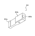
図8、9には、上記導電導入筒82に取付けられる従来のノズル84の一例が示されている。図8は斜視図、図9(A)は平面図、(B)は縦断面図、(C)は基端側からみた端面図である。
【0006】
このノズル84は、中心部に長さ方向に貫通する導線ガイド孔86を有している。また、ノズル84は、必要とされる強度を維持しつつステータコアのスロットへの挿入を可能にするため、先端部84aが基端部84bに比べて縮径されるとともに、導線ガイド孔86に垂直な断面が縦長の矩形とされ、この矩形断面の長手方向と前記導線導入筒82の軸方向とが同じ方向となるように前記ヘッド83に装着されている。
【0007】
そして、導線ガイド孔86の先端側開口部86a及び基端側開口部86bはテーパ状に拡径されている。この場合、各開口部86a、86bのテーパ孔は、導線ガイド孔86と同心的に形成されており、円形に広がった開口形状をなしている(図9(C)参照)。
【0008】
上記構造からなるノズル84を使用した巻線装置によれば、導線が、導線導入筒82から基端側開口部86bを経て導線ガイド孔86に導入され、導線ガイド孔86の先端側開口部86aを経て導出される。そして、導線ガイド孔86の開口部86a、86bがテーパ状をなすことにより、導線が導線ガイド孔86に導入又は導出される部分での摩擦力を低減させ、導線の絶縁被覆が損傷することを防止するようにしている。
【0009】
【発明が解決しようとする課題】
しかし、上記従来の巻線装置においては、ステータコア81の形状や、巻線条件等によって、導線ガイド孔86の開口部86bに導線が強く当たることがあり、絶縁被覆が損傷する場合があった。
【0010】
これを解決するため、例えば図10に示すように、導線ガイド孔86の開口部86bのテーパをもっと大きくすることが考えられる。なお、図10の(A)は平面図、(B)は縦断面図、(C)は基端側からみた端面図である。
【0011】
すなわち、このノズル91は、導線ガイド孔86の基端側開口部86bをより拡径させて、テーパ状の部分を長くとっている。
【0012】
しかしながら、前述したように、ノズル91は、図10(c)に示ように、基端面側から見て縦方向に長い長方形をなしており、開口部86bの直径を大きくしようとしても、両側壁に近接する部分までしか拡径できない。
【0013】
このため、導線ガイド孔86の軸方向に長くテーパをとることはできても、導線の経路を垂直方向から水平方向に移行させる曲面部分86cの曲率半径を大きくとることができなかった。
【0014】
その結果、導線が強く引っ張られることにより、上記曲面部分86cに押し付けられたときの局部的な接触圧を低下させることができず、絶縁被膜の損傷を効果的に防止できなかった。
【0015】
したがって、本発明の目的は、導線導入筒からノズルに導線をガイドする際に、ノズルの基端開口部における導線の接触圧をできるだけ低減させて、導線の絶縁被膜の損傷を効果的に防止できるようにしたステータコアへの巻線装置及び該装置に用いるノズルの製造方法を提供することにある。
【0016】
【課題を解決するための手段】
上記目的を達成するために、本発明のステータコアへの巻線装置は、ステータコアの中心に同軸的に配置され、所定角度で揺動すると共に、軸方向に往復移動する導線導入筒と、この導線導入筒の先端に装着され、導線を前記導線導入筒に対してほぼ直交する方向に繰り出すノズルとを備えたステータコアへの巻線装置において、前記ノズルの中心部には長さ方向に沿って導線ガイド孔が形成され、該導線ガイド孔の先端側及び基端側の開口部は、それぞれテーパ状に広がって形成されており、かつ、基端側の開口部におけるテーパ孔の中心は、前記導線ガイド孔の中心線に対して、前記導線導入筒の基端側に傾斜して形成され、前記ノズルの基端面から見たとき、前記基端側のテーパ孔が概略楕円形状をなし、この楕円に対して前記導線ガイド孔が前記導線導入筒の先端側に偏位していることを特徴とする。
【0017】
本発明では、上記のように、ノズルの基端側の開口部におけるテーパ孔の中心を、導線ガイド孔の中心線に対して、導線導入筒の基端側に傾斜して形成したことにより、ノズルの幅が狭くても開口部のテーパを大きくとることが可能となり、開口部における導線の接触圧が局部的に高くなるのを防止できる。その結果、導線の絶縁被膜が損傷することを確実に防止できる。
【0018】
本発明の好ましい態様においては、前記ノズルの前記導線ガイド孔に対して垂直な断面は、前記導線導入筒の軸方向に沿った長さが、それと直交する方向の長さよりも長い形状をなしている。
【0019】
この態様によれば、ステータコアのスロットに挿入しやすいようにノズルの幅を狭くすると共に、ノズルの縦方向の長さを長くとって必要とされる強度を維持することができ、そのような形状であっても、導線ガイド孔の開口部のテーパを大きくとることができる。
【0020】
また、本発明のステータコアへの巻線装置に使用されるノズルの製造方法は、ステータコアの中心に同軸的に配置され、所定角度で揺動すると共に、軸方向に往復移動する導線導入筒の先端に装着され、導線を前記導線導入筒に対してほぼ直交する方向に繰り出すノズルの製造方法において、先端に向けて次第に細くなった工具を用い、この工具を回転させながら、前記ノズルの基端面に該ノズルに形成される導線ガイド孔に対して傾斜した角度で押し当てて切削することにより、前記ノズルの基端面から見たとき、概略楕円形状をなし、この楕円に対して前記導線ガイド孔が前記導線導入筒の先端側に偏位するように、前記導線ガイド孔の基端側の開口部を拡径することを特徴とする。
【0021】
この方法によれば、導線導入筒に対して直交する方向に取付けられるノズルの導線導入側の開口部において、導線が導入される方向の内周を特に大きくテーパ状にすることができ、それによって導線とノズル内壁との接触圧を効果的に低減することが可能となる。
【0022】
また、導線ガイド孔に対して斜めに工具を当てて切削することにより、ノズルの基端面における開口部の形状が楕円形となるため、ノズルの幅が狭くても大きな内径のテーパ孔を形成することができる。
【0023】
本発明の好ましい態様によれば、前記ノズルの前記導線ガイド孔に対して垂直な断面は、前記導線導入筒の軸方向に沿った長さが、それと直交する方向の長さよりも長い形状をなし、前記工具を前記導線ガイド孔に対して、前記断面の長径方向に偏位した方向から傾斜した角度で押し当てる。
【0024】
この態様によれば、ノズルの幅を狭くしたので、ステータコアのスロットに挿入しやすく、ノズルの縦方向の長さを長くしたので、必要とされる強度を維持することができ、そのような形状であっても、前述したように、ノズルの基端面における開口部の形状が楕円形となるため、大きな内径のテーパ孔を形成することができる。
また、本発明のノズルの製造方法においては、前記工具を回転させながら、前記ノズルの基端面に該ノズルに形成される導線ガイド孔に対して傾斜した角度で押し当てて切削した後、前記工具を前記傾斜角が大きくなる方向に回動させて、前記開口部を広げることが好ましい。
【0025】
【発明の実施の形態】
図1〜4には、本発明のステータコアへの巻線装置の一実施形態が示されている。図1は同巻線装置の要部を示す正面断面図である。図2は図1におけるE−E’矢示線に沿った断面図である。図3は同巻線装置に使用されるノズルの斜視図である。図4は同巻線装置に使用されるノズルを示し、(A)は平面図、(B)は縦断面図、(C)は基端側からみた端面図である。
【0026】
この巻線装置11は、ステータコアの中心に同軸的に配置され、下端から導線が導入される導線導入筒12を有している。導線導入筒12の外周には、外筒13が装着されている。導線導入筒12及び外筒13は、軸受14に挿通されている。
【0027】
そして、導線導入筒12は、図示しない駆動機構を介して、図2中の矢印Aで示すように所定角度範囲で揺動(往復回動)すると共に、図1中の矢印Bで示すように軸方向に往復移動する。
【0028】
また、外筒13は、前記導線導入筒12と一緒に揺動し、かつ、軸方向に移動すると共に、図示しない駆動機構を介して、前記導線導入筒12に対して更に所定角度で揺動するようになっている。
【0029】
導線導入筒12の上端には、上部内外径が下部内外径に比べて縮径された段付き円筒部材15が被され、この段付き円筒部材15は、ネジ18によって導線導入筒12の上端部外周に固定されている。段付き円筒部材15の上部内周には、内周が曲面状をなすガイド環15aが配置され、導線導入筒12の上端から導出される導線を通過させて、後述するノズル23の導線ガイド孔31に導くようになっている。
【0030】
段付き円筒部材15の上部の縮径部外周には、環状のカム板21が回動可能に装着されている。そして、カム板21の上部には、ヘッド本体16が配置されている。ヘッド本体16は、ボルト19によって、段付き円筒部材15に固着されている。そして、カム板21は、段付き円筒部材15の拡径段部と、ヘッド本体16とに挟まれて保持されると共に、段付き円筒部材15及びヘッド本体16に対して回転できるようになっている。なお、上記ヘッド本体16、段付き円筒部材15及びカム板21が、本発明におけるヘッド17を構成している。
【0031】
ヘッド本体16の下面には、中心から等角度で半径方向外方に伸びる、3本の放射状のガイド溝22が形成されている。これらのガイド溝22に、それぞれノズル23の基部が挿入され、図2中の矢印Cで示すように、半径方向に移動可能に保持されている。
【0032】
一方、カム板21の上面には、各ガイド溝22に対応して、渦巻き状のカム溝24が形成されている。そして、ノズル23の下面に支軸25を介して取付けられたカムフォロア26が、上記渦巻き状のカム溝24に挿入されている。その結果、図示しない駆動機構によりカム板21がヘッド本体16に対して相対的に回動すると、カムフォロア26がカム溝24に沿って移動し、ノズル23がガイド溝22に沿って、図2中の矢印Cで示すように、半径方向に出没動作するようになっている。
【0033】
また、前記外筒13の上端部には、拡径部13aが形成されている。前記段付き円筒部材15の下部は、上記拡径部13aの内周に挿入され、前記カム板21は、ボルト27、28によって上記拡径部13aに固着されている。そして、段付き円筒部材15は、その拡径された下部を外筒13とカム板21との間で回転可能に保持されている。
【0034】
そして、外筒13は、図示しない駆動機構によって、導線導入筒12と一緒に回動及び軸方向移動すると共に、その状態で導線導入筒12に対して相対的に回転するようになっており、それによってカム板21がヘッド本体16に対して相対的に回転するようになっている。すなわち、カム板21は、ヘッド本体16と一緒に回動すると共に、巻線操作の過程でヘッド本体16に対しても相対的に回動する。その結果、前記のように、カム溝24に挿入されたカムフォロア26を介して、ノズル23を半径方向に出没動作させることができるようになっている。
【0035】
図3、4に示すように、ノズル23は、中心部に長さ方向に貫通する導線ガイド孔31を有している。また、ノズル23は、必要とされる強度を維持しつつステータコアのスロットへの挿入を可能にするため、先端部23aが縮径され、基端部23bが拡径されており、しかも導線ガイド孔31に垂直な断面が縦長の矩形(長方形)とされている。そして、その矩形断面の長手方向と前記導線導入筒12の軸方向とが同じ方向となるように、前記ヘッド本体16のガイド溝22に嵌装されている。なお、ノズル23の下面には、前記カムフォロワ26の支軸25の取付け孔32が設けられている。
【0036】
更に、導線ガイド孔31の先端側開口部31a及び基端側開口部31bはそれぞれ拡径され、それらの内周がテーパ状に形成されている。図4(B)に示ように、先端側開口部31aのテーパ孔は、その中心が導線ガイド孔31の中心線Lに重なるように同心状に形成されており、先端面から見たとき円形に広がった開口をなしている。
【0037】
一方、基端側開口部31bのテーパ孔は、その中心Mが、導線ガイド孔31の中心線Lに対して下方(ヘッド17に取付けられたとき導線導入筒12の基端側)に傾斜して形成されている。そして、ノズル23の基端面から見たとき、ノズル23の幅方向いっぱいに広がる概略楕円形状をなし、この楕円に対して上方に偏位して導線ガイド孔31が形成される(図4(C)参照)。
【0038】
ノズル23の基端側開口部31bのテーパ孔は、図6に示されるような工具を用い、図5に示される方法によって形成することができる。図5はノズル基端側開口部にテーパ孔を形成するときの工具の動きを示す説明図であり、図6は工具の概観を示す斜視図である。
【0039】
図6に示すように、上記工具41は、先端部41aが次第に細くなった形状、この実施形態では角錐形状をなしている。そして、角錐の角部41bによって切削がなされるようになっている。ただし、工具としては、上記形状のものに限らず、先端部が次第に細くなった形状をなすものであればよく、各種のものが使用可能である。
【0040】
図5に示すように、ノズル23の基端側開口部31bを前述したようなテーパ形状にするため、工具41を回転させながら、ノズル23の基端面から穿孔させる。このとき、ノズル23の長手方向に沿って予め形成しておいた導線ガイド孔31の中心線Lに対して、工具41を下方に傾斜させた角度で工具41を押し当てて穿孔を行う。また、工具41を突き当てて穿孔した後、その状態で工具41を図5の矢印Fで示すように下方に回動させることより、テーパ孔を更に広げることができる。
【0041】
こうして穿孔をすることにより、導線ガイド孔31の中心線Lに対して、傾斜した中心を有するテーパ孔を形成することができ、導線ガイド孔31の基端側開口部31bを前述したような形状のテーパ状に形成することができる。
【0042】
次に、この巻線装置11の作用について説明する。まず、図示しない駆動機構により、導電導入筒12が図2中の矢印Aで示すように所定角度で揺動(往復回動)すると共に、図1中の矢印Bで示すように軸方向に往復移動することにより、この導線導入筒12の上端部にヘッド17を介して取付けられた各ノズル23は、図示しないステータコアの対応する内歯の周りを周回する。
【0043】
そして、導線は、導線導入筒12の下端から導入され、上端から導出された後、段付き円筒部材15の環状ガイド15aで進路を変えて、ノズル23の導線ガイド孔31を通り、ノズル24の先端から繰り出され、ステータコアの内歯に巻付けられる。
【0044】
上記巻き付け操作と併行して、外筒13が導線導入筒12に対して相対的に回動し、外筒13に連接されたカム板21が、ヘッド本体16に対して相対的に往復回動する。その結果、カム板21のカム溝24に嵌合するカムフォロア26を介して、ノズル23が図2中の矢印Cで示すように半径方向に出没動作し、ステータコアの内歯の突出方向に沿って導線を整列させながら多層に巻き付けることができる。
【0045】
こうして、ノズル23が半径方向に出没動作する場合、特にノズル23が導線導入筒12に近接したとき、導線ガイド孔31の基端側開口部31bが導線導入筒12の上端開口部に近接する。その結果、導線ガイド孔31の基端側開口部31bのエッジに導線が強くあたり、絶縁被覆が損傷しやすくなる。
【0046】
しかしながら、本発明では、ノズル23の導線ガイド孔31の基端側開口部31bが、導線導入筒12の基端側に向けて傾斜した中心を有するテーパ状に形成されているので、導線導入筒12の上端から繰り出された導線が、上記緩やかなテーパ部を経て導線ガイド孔31内に導かれ、絶縁被覆の損傷を確実に防止することができる。
【0047】
なお、上記実施形態における巻線装置11は、ノズル23を半径方向に出没動作させることにより、ステータコアの内歯に導線を整列させて巻き付けるようにしているが、ステータコアの内歯の両端面に近接して、ステータコアの半径方向に伸びるガイド棒を配置し、このガイド棒先端に設けたテーパ面に沿って導線を滑り落とすようにして導線の巻付け位置をガイドし、このガイド棒を半径方向に徐々に進退動作させることにより、導線の巻付け位置を徐々にずらして内歯の半径方向に沿って均一に巻付けるようにした巻線装置にも、本発明は適用可能である。
【0048】
【発明の効果】
以上説明したように、本発明の巻線装置によれば、ズルの基端側の開口部におけるテーパ孔の中心を、導線ガイド孔の中心線に対して、導線導入筒の基端側に傾斜して形成したことにより、ノズルの幅が狭くても開口部のテーパを大きくとることが可能となり、開口部における導線の接触圧が局部的に高くなるのを防止できる。その結果、導線の絶縁被膜が損傷することを確実に防止できる。
【図面の簡単な説明】
【図1】本発明のステータコアへの巻線装置の一実施形態を示す正断面図である。
【図2】図1のE−E’矢示線に沿った断面図である。
【図3】同巻線装置に使用されるノズルの斜視図である。
【図4】同巻線装置に使用されるノズルを示し、(A)は平面図、(B)は縦断面図、(C)は基端側からみた端面図である。
【図5】本発明の巻線装置に使用されるノズルの製造方法の一実施形態を示し、ノズル基端側開口部にテーパを形成するときの工具の動きを示す説明図である。
【図6】同製造方法に使用する工具の概観を示す斜視図である。
【図7】従来の巻線装置を示す平面図である。
【図8】同巻線装置に使用されるノズルの斜視図である。
【図9】同巻線装置に使用されるノズルを示し、(A)は平面図、(B)は縦断面図、(C)は基端側からみた端面図である。
【図10】同巻線装置に使用されるノズルの他の形態を示し、(A)は平面図、(B)は縦断面図、(C)は基端側からみた端面図である。
【符号の説明】
11 巻線装置
12 導線導入筒
15 段付き円筒部材
16 ヘッド本体
17 ヘッド
21 カム板
22 ガイド溝
23 ノズル
24 カム溝
26 カムフォロア
31 導線ガイド孔
31a 先端側開口部
31b 基端側開口部
41 工具
41a 先端部[0001]
BACKGROUND OF THE INVENTION
The present invention relates to a winding device around a stator core in which a coil is formed by directly winding a conductive wire around an inner tooth of a stator core, and a method for manufacturing a nozzle used in the device.
[0002]
[Prior art]
A winding device that forms a coil by winding directly on the inner teeth of a stator core is generally arranged coaxially at the center of the stator core, swings at a predetermined angle, and reciprocates in the axial direction. And a nozzle that is attached to the leading end of the conducting wire introduction tube and feeds the conducting wire in a direction substantially orthogonal to the conducting wire introduction tube. The movement of the lead wire introduction tube causes the tip of the nozzle to circulate around the inner teeth of the stator core to be wound, and the lead wire fed from the nozzle is directly wound around the inner teeth to form a coil.
[0003]
FIG. 7 is a plan view showing an example of the conducting wire introducing cylinder as described above. In the figure,
[0004]
The conducting
[0005]
FIGS. 8 and 9 show an example of a
[0006]
The
[0007]
And the front end
[0008]
According to the winding device using the
[0009]
[Problems to be solved by the invention]
However, in the above-described conventional winding device, depending on the shape of the
[0010]
In order to solve this, for example, as shown in FIG. 10, it is conceivable to further increase the taper of the opening 86 b of the conductive
[0011]
That is, the
[0012]
However, as described above, as shown in FIG. 10C, the
[0013]
For this reason, even if it can taper long in the axial direction of the conducting
[0014]
As a result, when the conducting wire was pulled strongly, the local contact pressure when pressed against the
[0015]
Therefore, the object of the present invention is to reduce the contact pressure of the conductive wire at the proximal end opening of the nozzle as much as possible when guiding the conductive wire from the conductive wire introducing cylinder to the nozzle, thereby effectively preventing damage to the insulating coating of the conductive wire. An object of the present invention is to provide a winding device for a stator core and a method for manufacturing a nozzle used in the device.
[0016]
[Means for Solving the Problems]
In order to achieve the above object, a winding device for a stator core according to the present invention is arranged coaxially at the center of the stator core, swings at a predetermined angle, and reciprocates in the axial direction, and this conductor In a winding device to a stator core provided with a nozzle that is attached to the leading end of an introduction tube and feeds a conducting wire in a direction substantially perpendicular to the conducting wire introduction tube, a conducting wire is provided along the length direction at the center of the nozzle. A guide hole is formed, and the opening on the distal end side and the proximal end side of the conducting wire guide hole is formed to be tapered, and the center of the tapered hole in the opening on the proximal end side is the conducting wire. It is formed to be inclined toward the base end side of the lead wire introduction cylinder with respect to the center line of the guide hole, and when viewed from the base end surface of the nozzle, the taper hole on the base end side has a substantially elliptical shape. Against the conductor Wherein the de-holes are displaced on the distal end side of the wire introduction tube.
[0017]
In the present invention, as described above, the center of the tapered hole in the opening on the proximal end side of the nozzle is formed to be inclined toward the proximal end side of the conducting wire introduction cylinder with respect to the center line of the conducting wire guide hole. Even if the width of the nozzle is narrow, it is possible to increase the taper of the opening, and it is possible to prevent the contact pressure of the conducting wire in the opening from being locally increased. As a result, it is possible to reliably prevent damage to the insulating coating of the conductive wire.
[0018]
In a preferred aspect of the present invention, the cross section of the nozzle perpendicular to the conducting wire guide hole has a shape in which the length along the axial direction of the conducting wire introducing cylinder is longer than the length in the direction perpendicular thereto. Yes.
[0019]
According to this aspect, the width of the nozzle is narrowed so that it can be easily inserted into the slot of the stator core, and the required strength can be maintained by increasing the length of the nozzle in the vertical direction. Even so, the taper of the opening of the conducting wire guide hole can be increased.
[0020]
Further, the manufacturing method of the nozzle used in the winding device to the stator core according to the present invention is arranged coaxially at the center of the stator core, swings at a predetermined angle, and reciprocates in the axial direction. In the method of manufacturing a nozzle that feeds the lead wire in a direction substantially perpendicular to the lead wire introduction cylinder, a tool that is gradually narrowed toward the tip is used, and the tool is rotated on the base end surface of the nozzle while rotating the tool. By pressing and cutting at an inclined angle with respect to the conductive wire guide hole formed in the nozzle, when viewed from the base end surface of the nozzle, an approximately elliptical shape is formed, and the conductive wire guide hole is formed with respect to this ellipse. The diameter of the opening on the proximal end side of the conducting wire guide hole is increased so as to be displaced toward the distal end side of the conducting wire introducing cylinder .
[0021]
According to this method, the inner circumference in the direction in which the lead is introduced can be particularly greatly tapered at the opening on the lead introduction side of the nozzle attached in a direction orthogonal to the lead introduction tube, thereby It is possible to effectively reduce the contact pressure between the conductive wire and the nozzle inner wall.
[0022]
Also, by cutting the conductive wire guide hole obliquely with a tool, the shape of the opening at the base end face of the nozzle becomes elliptical, so a tapered hole with a large inner diameter is formed even if the width of the nozzle is narrow. be able to.
[0023]
According to a preferred aspect of the present invention, the cross section of the nozzle perpendicular to the conducting wire guide hole has a shape in which the length along the axial direction of the conducting wire introducing cylinder is longer than the length in the direction perpendicular thereto. The tool is pressed against the conductive wire guide hole at an angle inclined from the direction displaced in the major axis direction of the cross section.
[0024]
According to this aspect, since the width of the nozzle is reduced, it is easy to insert into the slot of the stator core, and the length in the vertical direction of the nozzle is increased, so that the required strength can be maintained, and such a shape Even so, as described above, since the shape of the opening in the base end face of the nozzle is elliptical, a tapered hole having a large inner diameter can be formed.
In the nozzle manufacturing method of the present invention, while rotating the tool, the tool is pressed against the base end surface of the nozzle at an angle inclined with respect to the conductive wire guide hole formed in the nozzle, and then the tool is cut. Is preferably rotated in the direction in which the inclination angle is increased to widen the opening.
[0025]
DETAILED DESCRIPTION OF THE INVENTION
1 to 4 show an embodiment of a winding device for a stator core according to the present invention. FIG. 1 is a front sectional view showing a main part of the winding device. FIG. 2 is a sectional view taken along the line EE ′ in FIG. FIG. 3 is a perspective view of a nozzle used in the winding device. 4A and 4B show nozzles used in the winding device, in which FIG. 4A is a plan view, FIG. 4B is a longitudinal sectional view, and FIG. 4C is an end view as seen from the base end side.
[0026]
The winding
[0027]
Then, the lead
[0028]
Further, the
[0029]
A stepped
[0030]
An
[0031]
Three
[0032]
On the other hand, a
[0033]
Further, an
[0034]
The
[0035]
As shown in FIGS. 3 and 4, the
[0036]
Further, the distal
[0037]
On the other hand, the taper hole of the base
[0038]
The taper hole of the base end side opening 31b of the
[0039]
As shown in FIG. 6, the
[0040]
As shown in FIG. 5, the base end side opening 31 b of the
[0041]
By drilling in this way, it is possible to form a tapered hole having an inclined center with respect to the center line L of the conducting
[0042]
Next, the operation of the winding
[0043]
Then, after the lead wire is introduced from the lower end of the lead
[0044]
In parallel with the winding operation, the
[0045]
Thus, when the
[0046]
However, in the present invention, the proximal end side opening 31b of the conducting
[0047]
In the winding
[0048]
【The invention's effect】
As described above, according to the winding device of the present invention, the center of the taper hole in the opening on the base end side of the slip is inclined toward the base end side of the lead wire introduction cylinder with respect to the center line of the lead wire guide hole. Thus, even if the width of the nozzle is narrow, it is possible to increase the taper of the opening, and it is possible to prevent the contact pressure of the conducting wire in the opening from being locally increased. As a result, it is possible to reliably prevent damage to the insulating coating of the conductive wire.
[Brief description of the drawings]
FIG. 1 is a front sectional view showing an embodiment of a winding device for a stator core according to the present invention.
2 is a cross-sectional view taken along the line EE ′ of FIG.
FIG. 3 is a perspective view of a nozzle used in the winding device.
4A and 4B show a nozzle used in the winding device, in which FIG. 4A is a plan view, FIG. 4B is a longitudinal sectional view, and FIG. 4C is an end view as seen from the base end side.
FIG. 5 is an explanatory view showing an embodiment of a method of manufacturing a nozzle used in the winding device of the present invention and showing the movement of a tool when a taper is formed in the nozzle proximal end opening.
FIG. 6 is a perspective view showing an overview of a tool used in the manufacturing method.
FIG. 7 is a plan view showing a conventional winding device.
FIG. 8 is a perspective view of a nozzle used in the winding device.
9A and 9B show a nozzle used in the winding device, wherein FIG. 9A is a plan view, FIG. 9B is a longitudinal sectional view, and FIG. 9C is an end view as seen from the base end side.
10A and 10B show another embodiment of the nozzle used in the winding device, wherein FIG. 10A is a plan view, FIG. 10B is a longitudinal sectional view, and FIG. 10C is an end view as seen from the base end side.
[Explanation of symbols]
DESCRIPTION OF
Claims (5)
Priority Applications (1)
| Application Number | Priority Date | Filing Date | Title |
|---|---|---|---|
| JP2001065317A JP4722306B2 (en) | 2001-02-21 | 2001-03-08 | Winding device for stator core and method of manufacturing nozzle used in the device |
Applications Claiming Priority (4)
| Application Number | Priority Date | Filing Date | Title |
|---|---|---|---|
| JP2001-45333 | 2001-02-21 | ||
| JP2001045333 | 2001-02-21 | ||
| JP2001045333 | 2001-02-21 | ||
| JP2001065317A JP4722306B2 (en) | 2001-02-21 | 2001-03-08 | Winding device for stator core and method of manufacturing nozzle used in the device |
Publications (2)
| Publication Number | Publication Date |
|---|---|
| JP2002325409A JP2002325409A (en) | 2002-11-08 |
| JP4722306B2 true JP4722306B2 (en) | 2011-07-13 |
Family
ID=26609832
Family Applications (1)
| Application Number | Title | Priority Date | Filing Date |
|---|---|---|---|
| JP2001065317A Expired - Lifetime JP4722306B2 (en) | 2001-02-21 | 2001-03-08 | Winding device for stator core and method of manufacturing nozzle used in the device |
Country Status (1)
| Country | Link |
|---|---|
| JP (1) | JP4722306B2 (en) |
Families Citing this family (3)
| Publication number | Priority date | Publication date | Assignee | Title |
|---|---|---|---|---|
| CN101627525B (en) | 2006-12-27 | 2012-06-13 | 东芝开利株式会社 | Winding method for stator, and permanent-magnet electric motor |
| KR200447800Y1 (en) | 2008-03-06 | 2010-02-19 | 이재남 | Paint delivery system for the non-acidic painting work |
| JP7378645B2 (en) * | 2020-12-17 | 2023-11-13 | 三菱電機株式会社 | Winding nozzle and winding machine |
Family Cites Families (4)
| Publication number | Priority date | Publication date | Assignee | Title |
|---|---|---|---|---|
| JPS51439A (en) * | 1974-06-19 | 1976-01-06 | Kyoshi Takeda | GOSEIJUSHISEISUNATSUPUFUASUNAAYOIKOMIKATANO SEISAKUHOHO |
| JP3048252B2 (en) * | 1991-03-15 | 2000-06-05 | 株式会社小田原エンジニアリング | Stator winding machine |
| JP3277007B2 (en) * | 1992-12-04 | 2002-04-22 | 日本電産シバウラ株式会社 | Winding device for small rotating electric machines |
| JP2000175415A (en) * | 1998-12-07 | 2000-06-23 | Sanko Kiki Kk | Device for winding to stator core |
-
2001
- 2001-03-08 JP JP2001065317A patent/JP4722306B2/en not_active Expired - Lifetime
Also Published As
| Publication number | Publication date |
|---|---|
| JP2002325409A (en) | 2002-11-08 |
Similar Documents
| Publication | Publication Date | Title |
|---|---|---|
| KR100974406B1 (en) | Winding device | |
| KR102012307B1 (en) | Stator manufacturing apparatus and stator manufacturing method | |
| JP2013135527A (en) | Method for manufacturing stator, apparatus for manufacturing stator and stator | |
| JP6785528B2 (en) | Winding device and winding method | |
| CN101675564A (en) | Centering device for insulation stripping equipment | |
| JP2002321871A (en) | Winding pitch speed automatic follow-up sending wire guide device for wire rod to winding bobbin | |
| JP4722306B2 (en) | Winding device for stator core and method of manufacturing nozzle used in the device | |
| US9982376B2 (en) | Bobbin holder | |
| JPH11276492A (en) | Surgical needle and forming device for needle material of surgical needle | |
| JP4214469B2 (en) | Segment conductor alignment method and alignment apparatus | |
| KR20200035960A (en) | Slew-actuated piercing of radial walls | |
| JP4813852B2 (en) | Winding terminal processing structure and processing method of rotating electrical machine stator | |
| CN106030945B (en) | Method and apparatus for cutting exposed insulating sections of a shield | |
| US6140732A (en) | Armature coil conductor and method of manufacture therefor | |
| JP2005110360A (en) | Coil insertion device and coil insertion method | |
| JP2002198245A (en) | Winding device and winding method | |
| JP4722509B2 (en) | Winding device to stator core | |
| KR20190098031A (en) | Tip structure of flat wire and method for manufacturing the tip structure | |
| JP2008061310A (en) | Winding device and winding method | |
| JP2003061320A (en) | Winding machine and winding method | |
| US20220411980A1 (en) | Lower thread winding device | |
| JPH0218548Y2 (en) | ||
| JP4526049B2 (en) | Ballpoint pen tip and manufacturing method thereof | |
| JP2010142004A (en) | Coil manufacturing method | |
| JP2009044942A (en) | Armature and winding end processing apparatus thereof |
Legal Events
| Date | Code | Title | Description |
|---|---|---|---|
| A621 | Written request for application examination |
Free format text: JAPANESE INTERMEDIATE CODE: A621 Effective date: 20080124 |
|
| A977 | Report on retrieval |
Free format text: JAPANESE INTERMEDIATE CODE: A971007 Effective date: 20101104 |
|
| A131 | Notification of reasons for refusal |
Free format text: JAPANESE INTERMEDIATE CODE: A131 Effective date: 20101109 |
|
| A521 | Request for written amendment filed |
Free format text: JAPANESE INTERMEDIATE CODE: A523 Effective date: 20101228 |
|
| TRDD | Decision of grant or rejection written | ||
| A01 | Written decision to grant a patent or to grant a registration (utility model) |
Free format text: JAPANESE INTERMEDIATE CODE: A01 Effective date: 20110322 |
|
| A01 | Written decision to grant a patent or to grant a registration (utility model) |
Free format text: JAPANESE INTERMEDIATE CODE: A01 |
|
| A61 | First payment of annual fees (during grant procedure) |
Free format text: JAPANESE INTERMEDIATE CODE: A61 Effective date: 20110406 |
|
| FPAY | Renewal fee payment (event date is renewal date of database) |
Free format text: PAYMENT UNTIL: 20140415 Year of fee payment: 3 |
|
| R150 | Certificate of patent or registration of utility model |
Ref document number: 4722306 Country of ref document: JP Free format text: JAPANESE INTERMEDIATE CODE: R150 Free format text: JAPANESE INTERMEDIATE CODE: R150 |
|
| R250 | Receipt of annual fees |
Free format text: JAPANESE INTERMEDIATE CODE: R250 |
|
| R250 | Receipt of annual fees |
Free format text: JAPANESE INTERMEDIATE CODE: R250 |
|
| R250 | Receipt of annual fees |
Free format text: JAPANESE INTERMEDIATE CODE: R250 |
|
| R250 | Receipt of annual fees |
Free format text: JAPANESE INTERMEDIATE CODE: R250 |
|
| R250 | Receipt of annual fees |
Free format text: JAPANESE INTERMEDIATE CODE: R250 |
|
| EXPY | Cancellation because of completion of term |