JP7377894B2 - Syntax signaling in subblock merge mode - Google Patents
Syntax signaling in subblock merge mode Download PDFInfo
- Publication number
- JP7377894B2 JP7377894B2 JP2021568037A JP2021568037A JP7377894B2 JP 7377894 B2 JP7377894 B2 JP 7377894B2 JP 2021568037 A JP2021568037 A JP 2021568037A JP 2021568037 A JP2021568037 A JP 2021568037A JP 7377894 B2 JP7377894 B2 JP 7377894B2
- Authority
- JP
- Japan
- Prior art keywords
- block
- motion vector
- sub
- affine
- candidates
- Prior art date
- Legal status (The legal status is an assumption and is not a legal conclusion. Google has not performed a legal analysis and makes no representation as to the accuracy of the status listed.)
- Active
Links
Images


Classifications
-
- H—ELECTRICITY
- H04—ELECTRIC COMMUNICATION TECHNIQUE
- H04N—PICTORIAL COMMUNICATION, e.g. TELEVISION
- H04N19/00—Methods or arrangements for coding, decoding, compressing or decompressing digital video signals
- H04N19/10—Methods or arrangements for coding, decoding, compressing or decompressing digital video signals using adaptive coding
- H04N19/102—Methods or arrangements for coding, decoding, compressing or decompressing digital video signals using adaptive coding characterised by the element, parameter or selection affected or controlled by the adaptive coding
- H04N19/103—Selection of coding mode or of prediction mode
- H04N19/109—Selection of coding mode or of prediction mode among a plurality of temporal predictive coding modes
-
- H—ELECTRICITY
- H04—ELECTRIC COMMUNICATION TECHNIQUE
- H04N—PICTORIAL COMMUNICATION, e.g. TELEVISION
- H04N19/00—Methods or arrangements for coding, decoding, compressing or decompressing digital video signals
- H04N19/50—Methods or arrangements for coding, decoding, compressing or decompressing digital video signals using predictive coding
- H04N19/503—Methods or arrangements for coding, decoding, compressing or decompressing digital video signals using predictive coding involving temporal prediction
- H04N19/51—Motion estimation or motion compensation
- H04N19/513—Processing of motion vectors
- H04N19/517—Processing of motion vectors by encoding
- H04N19/52—Processing of motion vectors by encoding by predictive encoding
-
- H—ELECTRICITY
- H04—ELECTRIC COMMUNICATION TECHNIQUE
- H04N—PICTORIAL COMMUNICATION, e.g. TELEVISION
- H04N19/00—Methods or arrangements for coding, decoding, compressing or decompressing digital video signals
- H04N19/10—Methods or arrangements for coding, decoding, compressing or decompressing digital video signals using adaptive coding
- H04N19/169—Methods or arrangements for coding, decoding, compressing or decompressing digital video signals using adaptive coding characterised by the coding unit, i.e. the structural portion or semantic portion of the video signal being the object or the subject of the adaptive coding
- H04N19/17—Methods or arrangements for coding, decoding, compressing or decompressing digital video signals using adaptive coding characterised by the coding unit, i.e. the structural portion or semantic portion of the video signal being the object or the subject of the adaptive coding the unit being an image region, e.g. an object
- H04N19/176—Methods or arrangements for coding, decoding, compressing or decompressing digital video signals using adaptive coding characterised by the coding unit, i.e. the structural portion or semantic portion of the video signal being the object or the subject of the adaptive coding the unit being an image region, e.g. an object the region being a block, e.g. a macroblock
-
- H—ELECTRICITY
- H04—ELECTRIC COMMUNICATION TECHNIQUE
- H04N—PICTORIAL COMMUNICATION, e.g. TELEVISION
- H04N19/00—Methods or arrangements for coding, decoding, compressing or decompressing digital video signals
- H04N19/10—Methods or arrangements for coding, decoding, compressing or decompressing digital video signals using adaptive coding
- H04N19/102—Methods or arrangements for coding, decoding, compressing or decompressing digital video signals using adaptive coding characterised by the element, parameter or selection affected or controlled by the adaptive coding
- H04N19/103—Selection of coding mode or of prediction mode
- H04N19/105—Selection of the reference unit for prediction within a chosen coding or prediction mode, e.g. adaptive choice of position and number of pixels used for prediction
-
- H—ELECTRICITY
- H04—ELECTRIC COMMUNICATION TECHNIQUE
- H04N—PICTORIAL COMMUNICATION, e.g. TELEVISION
- H04N19/00—Methods or arrangements for coding, decoding, compressing or decompressing digital video signals
- H04N19/10—Methods or arrangements for coding, decoding, compressing or decompressing digital video signals using adaptive coding
- H04N19/102—Methods or arrangements for coding, decoding, compressing or decompressing digital video signals using adaptive coding characterised by the element, parameter or selection affected or controlled by the adaptive coding
- H04N19/103—Selection of coding mode or of prediction mode
-
- H—ELECTRICITY
- H04—ELECTRIC COMMUNICATION TECHNIQUE
- H04N—PICTORIAL COMMUNICATION, e.g. TELEVISION
- H04N19/00—Methods or arrangements for coding, decoding, compressing or decompressing digital video signals
- H04N19/10—Methods or arrangements for coding, decoding, compressing or decompressing digital video signals using adaptive coding
- H04N19/134—Methods or arrangements for coding, decoding, compressing or decompressing digital video signals using adaptive coding characterised by the element, parameter or criterion affecting or controlling the adaptive coding
- H04N19/136—Incoming video signal characteristics or properties
- H04N19/137—Motion inside a coding unit, e.g. average field, frame or block difference
- H04N19/139—Analysis of motion vectors, e.g. their magnitude, direction, variance or reliability
-
- H—ELECTRICITY
- H04—ELECTRIC COMMUNICATION TECHNIQUE
- H04N—PICTORIAL COMMUNICATION, e.g. TELEVISION
- H04N19/00—Methods or arrangements for coding, decoding, compressing or decompressing digital video signals
- H04N19/10—Methods or arrangements for coding, decoding, compressing or decompressing digital video signals using adaptive coding
- H04N19/134—Methods or arrangements for coding, decoding, compressing or decompressing digital video signals using adaptive coding characterised by the element, parameter or criterion affecting or controlling the adaptive coding
- H04N19/157—Assigned coding mode, i.e. the coding mode being predefined or preselected to be further used for selection of another element or parameter
- H04N19/159—Prediction type, e.g. intra-frame, inter-frame or bidirectional frame prediction
-
- H—ELECTRICITY
- H04—ELECTRIC COMMUNICATION TECHNIQUE
- H04N—PICTORIAL COMMUNICATION, e.g. TELEVISION
- H04N19/00—Methods or arrangements for coding, decoding, compressing or decompressing digital video signals
- H04N19/10—Methods or arrangements for coding, decoding, compressing or decompressing digital video signals using adaptive coding
- H04N19/169—Methods or arrangements for coding, decoding, compressing or decompressing digital video signals using adaptive coding characterised by the coding unit, i.e. the structural portion or semantic portion of the video signal being the object or the subject of the adaptive coding
- H04N19/17—Methods or arrangements for coding, decoding, compressing or decompressing digital video signals using adaptive coding characterised by the coding unit, i.e. the structural portion or semantic portion of the video signal being the object or the subject of the adaptive coding the unit being an image region, e.g. an object
- H04N19/172—Methods or arrangements for coding, decoding, compressing or decompressing digital video signals using adaptive coding characterised by the coding unit, i.e. the structural portion or semantic portion of the video signal being the object or the subject of the adaptive coding the unit being an image region, e.g. an object the region being a picture, frame or field
-
- H—ELECTRICITY
- H04—ELECTRIC COMMUNICATION TECHNIQUE
- H04N—PICTORIAL COMMUNICATION, e.g. TELEVISION
- H04N19/00—Methods or arrangements for coding, decoding, compressing or decompressing digital video signals
- H04N19/10—Methods or arrangements for coding, decoding, compressing or decompressing digital video signals using adaptive coding
- H04N19/169—Methods or arrangements for coding, decoding, compressing or decompressing digital video signals using adaptive coding characterised by the coding unit, i.e. the structural portion or semantic portion of the video signal being the object or the subject of the adaptive coding
- H04N19/184—Methods or arrangements for coding, decoding, compressing or decompressing digital video signals using adaptive coding characterised by the coding unit, i.e. the structural portion or semantic portion of the video signal being the object or the subject of the adaptive coding the unit being bits, e.g. of the compressed video stream
-
- H—ELECTRICITY
- H04—ELECTRIC COMMUNICATION TECHNIQUE
- H04N—PICTORIAL COMMUNICATION, e.g. TELEVISION
- H04N19/00—Methods or arrangements for coding, decoding, compressing or decompressing digital video signals
- H04N19/46—Embedding additional information in the video signal during the compression process
-
- H—ELECTRICITY
- H04—ELECTRIC COMMUNICATION TECHNIQUE
- H04N—PICTORIAL COMMUNICATION, e.g. TELEVISION
- H04N19/00—Methods or arrangements for coding, decoding, compressing or decompressing digital video signals
- H04N19/50—Methods or arrangements for coding, decoding, compressing or decompressing digital video signals using predictive coding
- H04N19/503—Methods or arrangements for coding, decoding, compressing or decompressing digital video signals using predictive coding involving temporal prediction
- H04N19/51—Motion estimation or motion compensation
- H04N19/513—Processing of motion vectors
-
- H—ELECTRICITY
- H04—ELECTRIC COMMUNICATION TECHNIQUE
- H04N—PICTORIAL COMMUNICATION, e.g. TELEVISION
- H04N19/00—Methods or arrangements for coding, decoding, compressing or decompressing digital video signals
- H04N19/70—Methods or arrangements for coding, decoding, compressing or decompressing digital video signals characterised by syntax aspects related to video coding, e.g. related to compression standards
Landscapes
- Engineering & Computer Science (AREA)
- Multimedia (AREA)
- Signal Processing (AREA)
- Compression Or Coding Systems Of Tv Signals (AREA)
Description
[関連出願への相互参照]
本願は、2019年5月21日付けで出願された国際特許出願第PCT/CN2019/087805号に対する優先権及びその利益を請求して2020年5月21日付けで出願された国際特許出願第PCT/CN2020/091539号の国内移行である。上記の出願の開示全体は、本願の開示の部分として参照により援用される。
[Cross reference to related applications]
This application is filed as International Patent Application No. PCT/CN2019/087805 filed on May 21, 2019, claiming priority and benefit thereof. This is the national transition of PCT/CN2020/091539. The entire disclosure of the above application is incorporated by reference as part of the disclosure of this application.
本特許文献は、ビデオ符号化/復号化技術、デバイス、及びシステムに関する。 This patent document relates to video encoding/decoding techniques, devices, and systems.
ビデオ圧縮の進歩にかかわらず、デジタルビデオは依然として、インターネット及び他のデジタル通信ネットワーク上で最大バンド幅使用を占める。ビデオを受信及び表示することが可能なユーザデバイスの接続数が増えるにつれて、デジタルビデオ利用のためのバンド幅需要は成長し続けることが予期される。 Despite advances in video compression, digital video still accounts for the largest amount of bandwidth usage on the Internet and other digital communication networks. Bandwidth demands for digital video usage are expected to continue to grow as the number of connected user devices capable of receiving and displaying video increases.
本明細書は、サブブロックベースの動きベクトル精緻化を用いてビデオ符号化又は復号化が実行される様々な実施形態及び技術について記載する。一例となる態様では、視覚メディア処理の方法が開示される。方法は、視覚メディアデータのビットストリーム表現におけるアフィン適応動きベクトル分解(AMVR)技術に関する制御情報に応じて、前記視覚メディアデータに対して前記アフィンAMVR技術を使用すべきかどうかを決定するステップであり、前記制御情報は、規則に基づき前記ビットストリーム表現において包含又は削除される、前記決定するステップと、前記視覚メディアデータと該視覚メディアデータの前記ビットストリーム表現との間の変換を実行するステップとを含む。 This specification describes various embodiments and techniques in which video encoding or decoding is performed using sub-block-based motion vector refinement. In an example aspect, a method of visual media processing is disclosed. The method includes determining whether to use the affine adaptive motion vector decomposition (AMVR) technique for the visual media data in response to control information regarding the affine adaptive motion vector decomposition (AMVR) technique in a bitstream representation of the visual media data; the control information is included or deleted in the bitstream representation based on rules; and performing a transformation between the visual media data and the bitstream representation of the visual media data. include.
他の例となる態様では、視覚メディア処理の他の方法が開示される。方法は、サブブロックベースの時間的動きベクトル予測(subblock-based Temporal Motion Vector Prediction,sbTMVP)技術が視覚メディアデータに適用されるか否かの決定を行うステップと、該決定に応答して、前記視覚メディアデータに含まれる現在のビデオブロックについてサブブロックマージ候補リストを生成するステップと、該サブブロックマージ候補リストを用いて、前記現在のビデオブロックと該現在のビデオブロックのビットストリーム表現との間の変換を実行するステップとを含む。 In other example aspects, other methods of visual media processing are disclosed. The method includes the steps of: determining whether a subblock-based Temporal Motion Vector Prediction (sbTMVP) technique is applied to the visual media data; generating a sub-block merging candidate list for a current video block included in visual media data; and using the sub-block merging candidate list between the current video block and a bitstream representation of the current video block. and performing a transformation of the method.
更なる他の例となる態様では、視覚メディア処理の他の方法が開示される。方法は、現在のビデオブロックとビットストリーム表現との間の変換中に、該変換のためのサブブロックマージ候補リストに1つ以上のデフォルトのマージ候補を付け足すステップと、付け足された前記1つ以上のデフォルトのマージ候補を含む前記サブブロックマージ候補リストを用いて、前記変換を実行するステップとを含む。 In yet other exemplary aspects, other methods of visual media processing are disclosed. The method includes, during conversion between a current video block and a bitstream representation, appending one or more default merge candidates to a subblock merge candidate list for the conversion; and performing the conversion using the sub-block merging candidate list including the default merging candidates.
更なる他の例となる態様では、視覚メディア処理の他の方法が開示される。方法は、ビデオの現在のビデオブロックとビットストリーム表現との間の変換中に、該変換へのサブブロックベースの時間的動きベクトル予測(sbTMVP)の適用可能性を決定するステップであり、前記ビットストリーム表現中の1つ以上のビットが前記決定に対応する、前記決定するステップと、前記決定に基づき前記変換を実行するステップとを含む。 In yet other exemplary aspects, other methods of visual media processing are disclosed. The method includes, during a conversion between a current video block of a video and a bitstream representation, determining the applicability of sub-block-based temporal motion vector prediction (sbTMVP) to the conversion; The method includes the steps of determining, wherein one or more bits in the stream representation correspond to the determination, and performing the transformation based on the determination.
更なる他の例となる態様では、視覚メディア処理の他の方法が開示される。方法は、時間的動きベクトル予測(TMVP)ステップ又はサブブロックベースの時間的動きベクトル予測(sbTMVP)ステップに関連した条件に基づき選択的にサブブロックマージ候補リストを構成するステップと、該サブブロックマージ候補リストに基づき現在のビデオブロックと該現在のビデオブロックのビットストリーム表現との間の変換を実行するステップとを含む。 In yet other exemplary aspects, other methods of visual media processing are disclosed. The method includes the steps of: selectively configuring a sub-block merging candidate list based on conditions associated with a temporal motion vector prediction (TMVP) step or a sub-block-based temporal motion vector prediction (sbTMVP) step; performing a conversion between a current video block and a bitstream representation of the current video block based on the candidate list.
更なる他の例となる態様では、視覚メディア処理の他の方法が開示される。方法は、視覚メディアデータと該視覚メディアデータのビットストリーム表現との間の変換中に、前記視覚メディアデータに関連した同一位置(collocated)参照ピクチャに関する情報を決定するステップであり、前記情報は、時間動き情報にアクセスするコーディングモードが有効にされるかどうかに基づき前記ビットストリーム表現において包含又は削除される、前記決定するステップと、前記情報に従って前記同一位置参照ピクチャを決定するステップと、該同一位置参照ピクチャに基づき、前記視覚メディアデータと該視覚メディアデータの前記ビットストリーム表現との間の前記変換を実行するステップとを含む。 In yet other exemplary aspects, other methods of visual media processing are disclosed. The method includes determining information regarding collocated reference pictures associated with visual media data during conversion between visual media data and a bitstream representation of the visual media data, the information comprising: determining which co-located reference pictures are included or deleted in the bitstream representation based on whether a coding mode accessing temporal motion information is enabled; and determining the co-located reference pictures according to the information; performing the conversion between the visual media data and the bitstream representation of the visual media data based on position reference pictures.
更なる他の例となる態様では、視覚メディア処理の他の方法が開示される。方法は、視覚メディアデータのビデオブロックと前記視覚メディアデータのビットストリーム表現との間の変換を実行するステップと、該変換中に、規則に基づき前記ビットストリーム表現において包含又は削除される制御情報に応じて、オプティカルフローを使用した予測精緻化(Predictive Refinement using Optical Flow,PROF)を適用すべきかどうか決定するステップとを含む。 In yet other exemplary aspects, other methods of visual media processing are disclosed. The method includes the steps of: performing a conversion between a video block of visual media data and a bitstream representation of the visual media data; and, during the conversion, including or removing control information in the bitstream representation based on rules. Accordingly, determining whether to apply Predictive Refinement using Optical Flow (PROF).
更なる他の例となる態様では、上記の方法を実装するよう構成されたプロセッサを有するビデオ符号化及び/又は復号化装置が開示される。 In yet another example aspect, a video encoding and/or decoding apparatus is disclosed having a processor configured to implement the method described above.
更なる他の例となる態様では、コンピュータ可読媒体が開示される。コンピュータ可読媒体は、上記の方法の1つを具現するプロセッサ実行可能なコードを記憶している。 In yet another example aspect, a computer-readable medium is disclosed. A computer-readable medium stores processor-executable code that embodies one of the methods described above.
これら及び他の態様は、本明細書で更に記載される。 These and other aspects are described further herein.
セクション見出しは、理解を簡単にするために本明細書で使用されているのであって、セクションで開示されている実施形態をそのセクションにのみ制限するものではない。更に、特定の実施形態は、VVC(Versatile Video Coding)又は他の特定のビデオコーディングを参照して記載されているが、開示されている技術は、他のビデオコーディング技術にも適用可能である。更に、いくつかの実施形態は、ビデオコーディングステップについて詳述しているが、符号化を元に戻す対応する復号化ステップがデコーダによって実装されることが理解されるだろう。更に、ビデオ処理という用語は、ビデオ符号化又は圧縮、ビデオ復号化又は圧縮解除、及びビデオピクセルが1つの圧縮されたフォーマットから他の圧縮されたフォーマットに又は異なる圧縮ビットレートで表現されるビデオトランスコーディングを包含する。 Section headings are used herein for ease of understanding and do not limit the embodiments disclosed in a section to only that section. Furthermore, although certain embodiments are described with reference to Versatile Video Coding (VVC) or other specific video coding, the disclosed techniques are also applicable to other video coding techniques. Furthermore, while some embodiments detail a video coding step, it will be appreciated that a corresponding decoding step that undoes the encoding is implemented by the decoder. Additionally, the term video processing includes video encoding or compression, video decoding or decompression, and video transduction in which video pixels are represented from one compressed format to another or at different compression bit rates. Includes coding.
1.概要
本明細書は、ビデオコーディング技術に関係がある。具体的に、それは、ビデオコーディングにおける動きベクトルコーディングに関係がある。それは、HEVCのような既存のビデオコーディング標準規格、又はまとめられるべき標準規格(VVC)に適用されてもよい。それはまた、将来のビデオコーディング標準規格又はビデオコーデックにも適用可能であり得る。
1. Overview This specification relates to video coding techniques. Specifically, it concerns motion vector coding in video coding. It may be applied to existing video coding standards such as HEVC or standards to be compiled (VVC). It may also be applicable to future video coding standards or video codecs.
2.最初の議論
ビデオコーディング標準規格は、主として、よく知られているITU-T及びISO/IEC標準規格の開発を通じて、進化してきた。ITU-Tは、H.261及びH.263を作り出し、ISO/IECは、MPEG-1及びMPEG-4 Visualを作り出し、2つの組織は共同で、H.262/MPEG-2 Video及びH264/MPEG-4 AVC(Advanced Video Coding)並びにH.265/HEVC標準規格を作り出した。H.262以降、ビデオコーディング標準規格は、ハイブリッドビデオコーディング構造に基づいており、時間予測及び変換コーディングが利用される。HEVCを越える将来のビデオコーディング技術を探るために、JVET(Joint Video Exploration Team)が2015年にVCEG及びMPEGによって共同設立された。それ以来、多くの新しい方法がJVETによって導入され、JEM(Joint Exploration Model)と名付けられた参照ソフトウェアに置かれてきた[3,4]。2018年4月に、VCEG(Q6/16)とISO/IEC JTC1 SG29/WG11(MPEG)との間で、HEVCと比較してビットレート50%減を目指すVVC標準規格を研究するためのJVETJoint Video Experts Team)が作られた。
2. Initial Discussion Video coding standards have evolved primarily through the development of the well-known ITU-T and ISO/IEC standards. ITU-T is H. 261 and H. ISO/IEC created MPEG-1 and MPEG-4 Visual, and the two organizations jointly created H.263 and ISO/IEC created MPEG-1 and MPEG-4 Visual. H.262/MPEG-2 Video and H264/MPEG-4 AVC (Advanced Video Coding) and H.262/MPEG-2 Video and H.264/MPEG-4 AVC (Advanced Video Coding). Created the H.265/HEVC standard. H. Since H.262, video coding standards are based on a hybrid video coding structure, utilizing temporal prediction and transform coding. JVET (Joint Video Exploration Team) was co-founded by VCEG and MPEG in 2015 to explore future video coding technologies beyond HEVC. Since then, many new methods have been introduced by JVET and put into reference software named JEM (Joint Exploration Model) [3,4]. In April 2018, a JVET Joint Video was established between VCEG (Q6/16) and ISO/IEC JTC1 SG29/WG11 (MPEG) to study the VVC standard, which aims to reduce bit rates by 50% compared to HEVC. Experts Team) was created.
VVC草案(Versatile Video Coding (Draft 5))の最新バージョンは、phenix.it-sudparis.eu/jvet/doc_end_user/documents/14_Geneva/wg11/JVET-N1001-v5.zipで入手可能である。 The latest version of Versatile Video Coding (Draft 5) is available at phenix.it-sudparis.eu/jvet/doc_end_user/documents/14_Geneva/wg11/JVET-N1001-v5.zip.
VTMと名付けられたVVCの最新の参照ソフトウェアは、vcgit.hhi.fraunhofer.de/jvet/VVCSoftware_VTM/tags/VTM-5.0で入手可能である。 The latest reference software for VVC, named VTM, is available at vcgit.hhi.fraunhofer.de/jvet/VVCSoftware_VTM/tags/VTM-5.0.
2.1.HEVC/H.265でのインター予測
夫々のインター予測されたPU(prediction unit)は、1つ又は2つの参照ピクチャリストについての動きパラメータを有している。動きパラメータは、動きベクトル及び参照ピクチャインデックスを含む。2つの参照ピクチャリストの一方の利用は、inter_pred_idcを用いてシグナリングされてもよい。動きベクトルは、予測子に対する差分として明示的にコーディングされてもよい。
2.1. HEVC/H. Inter Prediction in H.265 Each inter predicted PU (prediction unit) has motion parameters for one or two reference picture lists. The motion parameters include a motion vector and a reference picture index. The use of one of the two reference picture lists may be signaled using inter_pred_idc. Motion vectors may be explicitly coded as a difference to a predictor.
CUがスキップモードでコーディングされる場合に、1つのPUがCUと関連付けられ、有意な残差係数、コーディングされた動きベクトル差分、又は参照ピクチャインデックスは、存在しない。マージモードが指定され、これによって、現在のPUの動きパラメータは、空間及び時間的候補を含む隣接PUから取得される。マージモードは、スキップモードのためだけでなく、如何なるインター予測されたPUにも適用可能である。マージモードに対する代替手段は、動きパラメータの明示的な伝送であり、動きベクトル(より厳密に言えば、動きベクトル予測子と比較した動きベクトル差分(motion vector differences,MVD))、各参照ピクチャリストの対応する参照ピクチャインデックス、及び参照ピクチャリスト利用が、各PUごとに明示的にシグナリングされる。このようなモードは、本開示ではアドバンスド動きベクトル予測(advanced motion vector prediction,AMVP)と呼ばれる。 When a CU is coded in skip mode, one PU is associated with the CU and there is no significant residual coefficient, coded motion vector difference, or reference picture index. A merge mode is specified, whereby the motion parameters of the current PU are obtained from neighboring PUs including spatial and temporal candidates. Merge mode is applicable to any inter-predicted PU, not only for skip mode. An alternative to merge mode is the explicit transmission of motion parameters, the motion vectors (more precisely, motion vector differences (MVD) compared to the motion vector predictor) of each reference picture list. The corresponding reference picture index and reference picture list usage are explicitly signaled for each PU. Such a mode is referred to in this disclosure as advanced motion vector prediction (AMVP).
2つの参照ピクチャリストの一方が使用されるべきであることをシグナリングが示す場合に、PUは、サンプルの1つのブロックから生成される。これは「片予測」(uni-prediction)と呼ばれる。片予測は、Pスライス及びBスライスの両方について利用可能である。 A PU is generated from one block of samples if the signaling indicates that one of the two reference picture lists should be used. This is called "uni-prediction." Unilateral prediction is available for both P and B slices.
両方の参照ピクチャリストが使用されるべきであることをシグナリングが示す場合に、PUは、サンプルの2つのブロックから生成される。これは「双予測」(bi-prediction)と呼ばれる。双予測は、Bスライスについてのみ利用可能である。 A PU is generated from two blocks of samples if the signaling indicates that both reference picture lists should be used. This is called "bi-prediction." Bi-prediction is only available for B slices.
下記は、HEVCで規定されているインター予測モードに関する詳細を提供する。記載はマージモードから始まる。 The following provides details regarding the inter-prediction mode defined in HEVC. The description begins in merge mode.
2.1.1.参照ピクチャリスト
HEVCでは、インター予測という用語が、現在のデコードされているピクチャ以外の参照ピクチャのデータ要素(例えば、サンプル値又は動きベクトル)から導出された予測を表すために使用される。同様に、H.264/AVCでは、ピクチャは、複数の参照ピクチャから予測され得る。インター予測のために使用される参照ピクチャは、1つ以上の参照ピクチャリストに編成される。参照インデックスは、リスト内のどの参照ピクチャが予測信号を生成するために使用されるべきであるかを識別する。
2.1.1. Reference Picture List In HEVC, the term inter prediction is used to refer to predictions derived from data elements (eg, sample values or motion vectors) of reference pictures other than the current picture being decoded. Similarly, H. In H.264/AVC, a picture may be predicted from multiple reference pictures. Reference pictures used for inter prediction are organized into one or more reference picture lists. The reference index identifies which reference picture in the list should be used to generate the prediction signal.
単一の参照ピクチャリストList0は、Pスライスのために使用され、2つの参照リストList0及びList1は、Bスライスのために使用される。留意されるべきは、List0/1に含まれる参照ピクチャは、捕捉/表示順序に関して過去及び未来のピクチャからであってよい点である。 A single reference picture list List0 is used for P slices, and two reference lists List0 and List1 are used for B slices. It should be noted that the reference pictures included in List0/1 may be from past and future pictures with respect to the capture/display order.
2.1.2.マージモード
2.1.2.1.マージモードのための候補の導出
PUがマージモードを用いて予測される場合に、merge candidates list(マージ候補リスト)内のエントリを指し示すインデックスは、ビットストリームからパースされ、動き情報を読み出すために使用される。このリストの構成は、HEVC標準規格で規定されており、次のステップの連続に従って手短に述べられ得る:
ステップ1:初期候補の導出
ステップ1.1:空間的候補の導出
ステップ1.2:空間的候補に対する冗長性検査
ステップ1.3:時間的候補の導出
ステップ2:追加候補の挿入
ステップ2.1:双予測候補の生成
ステップ2.2:ゼロ動き候補の挿入
2.1.2. Merge mode 2.1.2.1. Candidate Derivation for Merge Mode When a PU is predicted using merge mode, an index pointing to an entry in the merge candidates list is parsed from the bitstream and used to read the motion information. be done. The composition of this list is specified in the HEVC standard and can be briefly described according to the following sequence of steps:
Step 1: Derivation of initial candidates Step 1.1: Derivation of spatial candidates Step 1.2: Redundancy check on spatial candidates Step 1.3: Derivation of temporal candidates Step 2: Insertion of additional candidates Step 2.1 : Generation of bi-predictive candidates Step 2.2: Insertion of zero motion candidates
これらのステップは、図1でも概略的に説明されている。初期マージ候補の導出のために、最大4つのマージ候補が、5つの異なった位置にある候補の中から選択される。時間マージ候補の導出のために、最大1つのマージ候補が、2つの候補の中から選択される。PUごとの一定数の候補がデコーダで考えられているので、ステップ1から取得された候補の数が、スライスヘッダでシグナリングされているマージ候補の最大数(MaxNumMergeCand)に達しない場合には、追加候補が生成される。候補の数は一定であるから、最良のマージ候補のインデックスは、トランケーテッドユーナリー二値化(truncated unary binarization,TU)を用いて符号化される。CUのサイズが8に等しい場合に、現在のCUの全てのPUは、2N×2N予測ユニットのマージ候補リストと同一である単一のマージ候補リストを共有する。
These steps are also schematically illustrated in FIG. For the derivation of initial merge candidates, up to four merge candidates are selected among the candidates in five different positions. For the derivation of temporal merge candidates, at most one merge candidate is selected from the two candidates. Since a fixed number of candidates per PU is considered in the decoder, if the number of candidates obtained from
以下では、上記のステップに関連した動作が詳述される。 In the following, operations related to the above steps are detailed.
図1は、マージ候補リスト構成のための導出プロセスの例を示す。 FIG. 1 shows an example of a derivation process for merging candidate list construction.
2.1.2.2.空間的候補の導出
空間マージ候補の導出において、最大4つのマージ候補が、図2に表されている位置にある候補の中から選択される。導出の順序は、A1、B1、B0、A0、及びB2である。位置B2は、位置A1、B1、B0、A0のいずれかのPU(それが他のスライス又はタイルに属するために)利用可能でないか、あるいは、イントラコーディングされている場合にのみ検討される。位置A1での候補が加えられた後、残りの候補の追加は冗長性検査を受ける。これは、同じ動き情報を有する候補が、コーディング効率が改善されるようにリストから外されることを確かにする。
2.1.2.2. Derivation of Spatial Candidates In deriving spatial merging candidates, up to four merging candidates are selected among the candidates at the positions represented in FIG. 2. The order of derivation is A 1 , B 1 , B 0 , A 0 , and B 2 . Location B 2 is only available if any of the PUs at locations A 1 , B 1 , B 0 , A 0 are not available (because they belong to other slices or tiles) or are intra-coded. Will be considered. After the candidate at position A1 is added, the addition of the remaining candidates is subject to a redundancy check. This ensures that candidates with the same motion information are removed from the list so that coding efficiency is improved.
計算複雑性を低減するために、上記の冗長性検査において、可能性がある全ての候補対が検討されるわけではない。代わりに、図3において矢印で結ばれている対が検討され、候補は、冗長性検査のために使用された対応する候補が同じ動き情報を有していない場合にのみリストに加えられる。そっくり同じ動き情報の他のソースは、2N×2Nとは異なるパーティションに関連した「第2PU」である。例として、図4は、夫々、N×2N及び2N×Nの場合について、第2PUを表す。現在のPUがN×2Nとしてパーティション化される場合に、位置A1での候補はリスト構成のために考慮に入れられない。実際に、この候補を加えることで、同じ動き情報を有する2つの予測ユニットが生じることになり、これは、コーディングユニット内でただ1つのPUを有するには冗長である。同様に、位置B1は、現在のPUが2N×Nとしてパーティション化される場合に考慮に入れられない。 In order to reduce computational complexity, not all possible candidate pairs are considered in the above redundancy check. Instead, the pairs connected by arrows in FIG. 3 are considered and a candidate is added to the list only if the corresponding candidate used for redundancy check does not have the same motion information. Another source of exactly the same motion information is a "second PU" associated with a different partition than 2Nx2N. As an example, FIG. 4 represents the second PU for the N×2N and 2N×N cases, respectively. If the current PU is partitioned as N×2N, the candidate at position A1 is not taken into account for list construction. In fact, adding this candidate will result in two prediction units with the same motion information, which is redundant to have only one PU in the coding unit. Similarly, location B 1 is not taken into account when the current PU is partitioned as 2N×N.
2.1.2.3.時間的候補の導出
このステップでは、ただ1つの候補がリストに加えられる。特に、この時間マージ候補の導出において、スケーリングされた動きベクトルは、所与の参照ピクチャリスト内で現在のピクチャとのPOC差が最小であるピクチャに属する同一位置(co-located)PUに基づいて導出される。同一位置PUの導出のために使用される参照ピクチャリストは、スライスヘッダで明示的にシグナリングされる。時間マージ候補のスケーリングされた動きベクトルは、図5で破線によって表されるように取得され、POC距離tb及びtdを用いて同一位置PUの動きベクトルからスケーリングされている。tbは、現在のピクチャの参照ピクチャと現在のピクチャとの間のPOC距離であるよう定義され、tdは、同一位置ピクチャの参照ピクチャと同一位置ピクチャとの間のPOC差であるよう定義される。時間マージ候補の参照ピクチャインデックスは、ゼロに等しくセットされる。スケーリングプロセスの実際の実現は、HEVC規格で記載されている。Bスライスについては、2つの動きベクトル(1つは参照ピクチャリスト0用であり、もう1つは参照ピクチャリスト1用である)が取得され、双予測マージ候補を生成するよう結合される。
2.1.2.3. Derivation of temporal candidates In this step, only one candidate is added to the list. In particular, in deriving this temporal merge candidate, the scaled motion vector is based on the co-located PU belonging to the picture with the smallest POC difference with the current picture within a given reference picture list. derived. The reference picture list used for the derivation of co-located PUs is explicitly signaled in the slice header. The scaled motion vector of the temporal merge candidate is obtained as represented by the dashed line in FIG. 5 and has been scaled from the motion vector of the co-located PU using the POC distances tb and td. tb is defined to be the POC distance between the reference picture of the current picture and the current picture, and td is defined to be the POC difference between the reference picture of the co-located picture and the co-located picture. . The reference picture index of the temporal merge candidate is set equal to zero. The actual implementation of the scaling process is described in the HEVC standard. For the B slice, two motion vectors (one for
図5は、時間マージ候補の動きベクトルスケーリングの実例である。 FIG. 5 is an illustration of motion vector scaling for temporal merge candidates.
参照フレームに属する同一位置PU(Y)では、時間的候補の位置が、図6に表されているように、候補C0及びC1の間で選択される。位置C0にあるPUが利用可能でないか、イントラコーディングされているか、あるいは、現在のコーディングツリーユニット(Coding Tree Unit,CTU、別名最大コーディングユニット(Largest Coding Unit,LCU)行の外にある場合に、位置C1が使用される。そうでない場合には、位置C0が時間マージ候補の導出において使用される。 For the same position PU(Y) belonging to the reference frame, the position of the temporal candidate is selected between the candidates C 0 and C 1 , as represented in FIG. If the PU at position C 0 is not available, is intra-coded, or is outside the current Coding Tree Unit (CTU, also known as Largest Coding Unit, LCU) row. , position C 1 is used. Otherwise, position C 0 is used in deriving the temporal merge candidate.
図6は、時間マージ候補の候補位置C0及びC1の例を示す。 FIG. 6 shows an example of candidate positions C0 and C1 of temporal merging candidates.
2.1.2.4.追加候補の挿入
空間及び時間マージ候補に加えて、2つの更なるタイプのマージ候補、すなわち、複合双予測マージ候補(combined bi-predictive merge candidate)及びゼロマージ候補(zero merge candidate)が存在する。複合双予測マージ候補は、空間及び時間マージ候補を利用することによって生成される。複合双予測マージ候補は、Bスライスにのみ使用される。複合双予測マージ候補は、最初の候補の第1参照ピクチャリスト動きパラメータを他の第2参照ピクチャリスト動きパラメータと組み合わせることによって生成される。これら2つのタプルが異なった動き仮説(hypotheses)をもたらす場合に、それらは新しい双予測候補を形成することになる。一例として、図7は、mvL0及びrefIdxL0又はmvL1及びrefIdx1を有する原リスト(左側にある)内の2つの候補が、最終的なリスト(右側にある)に加えられる複合双予測マージ候補を生成するために使用される場合を表す。これらの追加マージ候補を生成するために考えられる組み合わせに関して多数の規則がある。
2.1.2.4. Insertion of Additional Candidates In addition to spatial and temporal merge candidates, there are two additional types of merge candidates: combined bi-predictive merge candidates and zero merge candidates. A composite bi-predictive merge candidate is generated by utilizing spatial and temporal merge candidates. Composite bi-predictive merge candidates are used only for B slices. A composite bi-predictive merge candidate is generated by combining the first reference picture list motion parameters of the first candidate with other second reference picture list motion parameters. If these two tuples yield different motion hypotheses, they will form a new bi-prediction candidate. As an example, Figure 7 generates a composite bi-predictive merge candidate where two candidates in the original list (on the left) with mvL0 and refIdxL0 or mvL1 and refIdx1 are added to the final list (on the right) Represents the case where it is used for. There are a number of rules regarding possible combinations to generate these additional merge candidates.
ゼロ動き候補は、マージ候補リスト内の残りのエントリを満たして、MaxNumMergeCand容量に達するよう挿入される。これらの候補は、ゼロ空間変位と、ゼロから始まって、新しいゼロ動き候補がリストに加えられるたびに増える参照ピクチャインデックスとを有している。 Zero motion candidates are inserted to fill the remaining entries in the merge candidate list to reach the MaxNumMergeCand capacity. These candidates have zero spatial displacement and a reference picture index that starts at zero and increases each time a new zero motion candidate is added to the list.
より具体的には、次のステップが、マージリストが一杯になるまで順番に実行される:
1.Pスライスについては、リスト0に関連した参照ピクチャの数、又はBスライスについては、2つのリスト内の参照ピクチャの最小数、のどちらか一方に変数numRefをセットする;
2.非反復的なゼロ動き候補を加える;
0・・・numRef-1である変数iについては、(0,0)にセットされたMVと、リスト0(Pスライスの場合)について又は両方のリスト(Bスライスの場合)についてiにセットされた参照ピクチャインデックスとを有するデフォルトの動き候補を加える。
3.(0,0)にセットされたMVと、0にセットされたリスト0(Pスライスの場合)の参照ピクチャインデックスと、0にセットされた両方のリスト(Bスライスの場合)の参照ピクチャインデックスとを有する反復的なゼロ動き候補を加える。
More specifically, the following steps are executed in order until the merge list is full:
1. For P slices, set the variable numRef to either the number of reference pictures associated with
2. Add non-repetitive zero motion candidates;
0...numRef-1 for variable i, with MV set to (0,0) and i set for list 0 (for P slices) or for both lists (for B slices). Add a default motion candidate with the reference picture index.
3. MV set to (0,0), the reference picture index of list 0 (for P slices) set to 0, and the reference picture index of both lists (for B slices) set to 0. Add iterative zero motion candidates with .
最後に、それらの候補に対して冗長性検査は実行されない。 Finally, no redundancy check is performed on those candidates.
2.1.3.AMVP
AMVP(Advanced Motion Vector Prediction)は、動きパラメータの明示的な伝送のために使用される隣接PUとの動きベクトルの空間時間相関を利用する。参照ピクチャリストごとに、動きベクトル候補リストは、左及び上にある時間的に隣接したPU位置の利用可能性を最初に確認し、冗長な候補を除いて、候補リストを一定の長さにするようゼロベクトルを加えることによって、構成される。次いで、エンコーダは、候補リストから最良の予測子を選択し、選択された候補を示す対応するインデックスを送信することができる。同様に、マージインデックスシグナリングにより、最良の動きベクトル候補のインデックスは、トランケーテッドユーナリー(truncated unary)を用いて符号化される。この場合に符号化される最大値は2である(図8を参照)。以下のセクションでは、動きベクトル予測候補の導出プロセスに関する詳細が提供される。
2.1.3. AMVP
Advanced Motion Vector Prediction (AMVP) exploits the spatio-temporal correlation of motion vectors with neighboring PUs, which is used for explicit transmission of motion parameters. For each reference picture list, the motion vector candidate list first checks the availability of temporally adjacent PU positions on the left and above, and removes redundant candidates to make the candidate list a constant length. It is constructed by adding the zero vector as follows. The encoder may then select the best predictor from the candidate list and send a corresponding index indicating the selected candidate. Similarly, with merge index signaling, the index of the best motion vector candidate is encoded using a truncated unary. The maximum value encoded in this case is 2 (see Figure 8). In the following sections, details regarding the derivation process of motion vector prediction candidates are provided.
2.1.3.1.AMVP候補の導出
図8は、動きベクトル予測候補の導出プロセスを要約する。
2.1.3.1. Derivation of AMVP Candidates Figure 8 summarizes the process of deriving motion vector prediction candidates.
動きベクトル予測では、2つのタイプの動きベクトル候補、すなわち、空間動きベクトル候補及び時間動きベクトル候補、が考えられている。空間動きベクトル候補導出については、2つの動きベクトル候補が、図2に表されるように5つの異なった位置にある各PUの動きベクトルに基づいて最終的に導出される。 In motion vector prediction, two types of motion vector candidates are considered: spatial motion vector candidates and temporal motion vector candidates. For spatial motion vector candidate derivation, two motion vector candidates are finally derived based on the motion vectors of each PU at five different positions as depicted in FIG.
時間動きベクトル候補導出については、2つの異なった同一位置の位置に基づいて導出される2つの候補から、1つの動きベクトル候補が選択される。空間時間的候補の第1リストが生成された後、リスト内の重複した動きベクトル候補が除かれる。潜在的な候補の数が2つよりも多い場合には、関連する参照ピクチャリスト内の参照ピクチャインデックスが1よりも大きい動きベクトル候補は、リストから除かれる。空間時間動きベクトル候補の数が2つよりも少ない場合には、追加のゼロ動きベクトル候補がリストに加えられる。 Regarding temporal motion vector candidate derivation, one motion vector candidate is selected from two candidates derived based on two different positions of the same position. After the first list of spatiotemporal candidates is generated, duplicate motion vector candidates in the list are removed. If the number of potential candidates is greater than two, motion vector candidates with a reference picture index greater than 1 in the associated reference picture list are removed from the list. If the number of spatio-temporal motion vector candidates is less than two, additional zero motion vector candidates are added to the list.
2.1.3.2.空間動きベクトル候補
空間動きベクトル候補の導出において、図2に表されるような位置(これらの位置は、動きマージのそれらと同じである)にあるPUから導出される5つの潜在的な候補から、最大2つの候補が考えられる。現在のPUの左側の導出の順序は、A0、A1及びスケーリングされたA0、スケーリングされたA1として定義される。現在のPUの上側の導出の順序は、B0、B1、B2、スケーリングされたB0、スケーリングされたB1、スケーリングされたB2として定義される。夫々の側について、従って、動きベクトル候補として使用され得る4つの場合が存在し、2つの場合は、空間スケーリングを使用することが不要であり、他の2つの場合には、空間スケーリングが使用される。4つの異なる場合は、次のように簡単に述べられる。
・空間スケーリングなし
(1)同じ参照ピクチャリスト、かつ同じ参照ピクチャインデックス(同じPOC)
(2)異なる参照ピクチャリスト、しかし同じ参照ピクチャ(同じPOC)
・空間スケーリング
(3)同じ参照ピクチャリスト、しかし異なる参照ピクチャ(異なるPOC)
(4)異なる参照ピクチャリスト、かつ異なる参照ピクチャ(異なるPOC)
2.1.3.2. Spatial Motion Vector Candidates In deriving the spatial motion vector candidates, from the five potential candidates derived from the PUs at the positions as represented in Fig. 2 (these positions are the same as those for motion merging). , a maximum of two candidates are possible. The order of derivation on the left side of the current PU is defined as A 0 , A 1 and scaled A 0 , scaled A 1 . The order of the upper derivation of the current PU is defined as B 0 , B 1 , B 2 , scaled B 0 , scaled B 1 , scaled B 2 . For each side, there are therefore four cases that can be used as motion vector candidates, two cases where it is unnecessary to use spatial scaling, and two other cases where spatial scaling is used. Ru. The four different cases are briefly stated as follows.
- No spatial scaling (1) Same reference picture list and same reference picture index (same POC)
(2) Different reference picture list, but same reference picture (same POC)
・Spatial scaling (3) Same reference picture list, but different reference pictures (different POC)
(4) Different reference picture lists and different reference pictures (different POC)
空間スケーリングなしの場合が最初に確認され、その後に空間スケーリングが続く。空間スケーリングは、参照ピクチャリストにかかわらず隣接PUの参照ピクチャと現在のPUのそれとの間でPOCが異なる場合に考えられる。左の候補の全てのPUが利用不可能であるか、又はイントラコーディングされている場合に、上の動きベクトルのスケーリングが、左及び上のMV候補の並列導出を助けるよう可能にされる。そうでない場合には、空間スケーリングは、上の動きベクトルに対して認められないい。 The case without spatial scaling is checked first, followed by spatial scaling. Spatial scaling is considered when the POC is different between the reference picture of a neighboring PU and that of the current PU regardless of the reference picture list. If all PUs of the left candidate are unavailable or intra-coded, scaling of the top motion vectors is enabled to help parallel derivation of the left and top MV candidates. Otherwise, no spatial scaling is allowed for the above motion vectors.
図9は、空間動きベクトル候補のための動きベクトルスケーリングの実例である。 FIG. 9 is an illustration of motion vector scaling for spatial motion vector candidates.
空間スケーリングプロセスでは、隣接PUの動きベクトルは、図9に表されるように、時間スケーリングの場合と同じようにしてスケーリングされる。主な違いは、現在のPUの参照ピクチャリスト及びインデックスが入力として与えられる点であり、実際のスケーリングプロセスは時間スケーリングのそれと同じである。 In the spatial scaling process, the motion vectors of neighboring PUs are scaled in the same way as for temporal scaling, as depicted in FIG. The main difference is that the reference picture list and index of the current PU are given as input, and the actual scaling process is the same as that of temporal scaling.
2.1.3.3.時間動きベクトル候補
参照ピクチャインデックス導出は別として、時間マージ候補の導出のための全てのプロセスは、空間動きベクトル候補の導出(図6を参照)の場合と同じである。参照ピクチャインデックスはデコーダへシグナリングされる。
2.1.3.3. Temporal Motion Vector Candidates Apart from the reference picture index derivation, all processes for the derivation of temporal merging candidates are the same as for the derivation of spatial motion vector candidates (see Figure 6). The reference picture index is signaled to the decoder.
2.2.JEMにおけるサブCUに基づいた動きベクトル予測方法
四分木プラス二分木(quadtrees plus binary trees,QTBT)によるJEMでは、各CUは、予測方向ごとに多くてもひと組の動きパラメータを有することができる。2つのサブCUレベル動きベクトル予測方法が、大きいCUをサブCUに分割し、大きいCUの全てのサブCUについて動き情報を導出することによって、エンコーダにおいて考えられている。代替時間動きベクトル予測(ATMVP)方法は、各CUが、同一位置の参照ピクチャにある現在のCUよりも小さい複数のブロックから複数の組の動き情報をフェッチすることを可能にする。空間時間動きベクトル予測(STMVP)方法では、サブCUの動きベクトルは、時間動きベクトル予測子及び空間隣接動きベクトルを使用することによって再帰的に導出される。
2.2. Motion vector prediction method based on sub-CUs in JEM In JEM using quadtrees plus binary trees (QTBT), each CU can have at most one set of motion parameters for each prediction direction. . Two sub-CU level motion vector prediction methods are considered in the encoder by dividing a large CU into sub-CUs and deriving motion information for all sub-CUs of the large CU. Alternative temporal motion vector prediction (ATMVP) methods allow each CU to fetch sets of motion information from blocks smaller than the current CU in co-located reference pictures. In the spatiotemporal motion vector prediction (STMVP) method, a sub-CU's motion vector is recursively derived by using a temporal motion vector predictor and a spatially adjacent motion vector.
サブCU動き予測のためのより正確な運動場を保つために、参照フレームのための動き圧縮は目下無効にされている。 To keep a more accurate motion field for sub-CU motion estimation, motion compression for reference frames is currently disabled.
図10は、CUに対するATMVP動き予測の例を示す。 FIG. 10 shows an example of ATMVP motion prediction for a CU.
2.2.1.代替時間動きベクトル予測
代替時間動きベクトル予測(Alternative Temporal Motion Vector Prediction,ATMVP)法では、動きベクトルの時間動きベクトル予測(Temporal Motion Vector Prediction,TMVP)が、現在のCUよりも小さいブロックから複数の組の動き情報(動きベクトル及び参照インデックスを含む)をフェッチすることによって改良されている。CUは、正方N×Nブロックである(Nはデフォルトで4にセットされる)。
2.2.1. Alternative Temporal Motion Vector Prediction In the Alternative Temporal Motion Vector Prediction (ATMVP) method, temporal motion vector prediction (Temporal Motion Vector Prediction, TMVP) of a motion vector is performed using multiple sets of blocks smaller than the current CU. is improved by fetching motion information (including motion vectors and reference indices) of A CU is a square N×N block (N is set to 4 by default).
ATMVPは、2つのステップでCU内のサブCUの動きベクトルを予測する。最初のステップは、いわゆる時間ベクトルにより参照ピクチャ内の対応するブロックを識別することである。参照ピクチャは、モーションソースピクチャ(motion source picture)と呼ばれる。第2のステップは、現在のCUをサブCUに分け、各サブCUに対応するブロックから各サブCUの動きベクトル及び参照インデックスを取得することである。 ATMVP predicts motion vectors of sub-CUs within a CU in two steps. The first step is to identify the corresponding block in the reference picture by a so-called temporal vector. A reference picture is called a motion source picture. The second step is to divide the current CU into sub-CUs and obtain the motion vector and reference index of each sub-CU from the block corresponding to each sub-CU.
最初のステップで、参照ピクチャ及び対応するブロックは、現在のCUの空間隣接ブロックの動き情報によって決定される。隣接ブロックの反復的な走査プロセスを回避するために、現在のCUのマージ候補リスト内の最初のマージ候補が使用される。最初の利用可能な動きベクトル及びその関連する参照インデックスが、時間ベクトルと、モーションソースピクチャへのインデックスとであるようセットされる。このようにして、ATMVPでは、対応するブロックは、TMVPと比較して、より正確に識別され得る。ここで、対応するブロック(時々、同一位置ブロックと呼ばれる)は、現在のCUに対して右下又は中心位置に常にある。 In the first step, the reference picture and the corresponding block are determined by the motion information of the spatial neighboring blocks of the current CU. The first merge candidate in the current CU's merge candidate list is used to avoid the iterative scanning process of neighboring blocks. The first available motion vector and its associated reference index are set to be a temporal vector and an index to the motion source picture. In this way, in ATMVP the corresponding blocks can be identified more accurately compared to TMVP. Here, the corresponding block (sometimes called co-located block) is always at the bottom right or center position relative to the current CU.
第2のステップで、サブCUの対応するブロックは、モーションソースピクチャの時間ベクトルによって、現在のCUの座標にその時間ベクトルを加えることによって識別される。各サブCUについて、その対応するブロック(中心サンプルをカバーする最小モーショングリッド)の動き情報が、当該サブCUの動き情報を導出するために使用される。対応するN×Nブロックの動き情報が識別された後、それは、HEVCのTMVPと同じように、現在のサブCUの動きベクトル及び参照インデックスに変換される。このとき、動きスケーリング及び他のプロシージャが適用される。例えば、デコーダは、低遅延条件(すなわち、現在のピクチャの全ての参照ピクチャのPOCが現在のピクチャのPOCよりも小さい)が満足されるかどうかを確認し、場合により、各サブCUについて動きベクトルMVy(Xは0又は1に等しく、Yは1-Xに等しい)を予測するために動きベクトルMVx(参照ピクチャリストXに対応する動きベクトル)を使用する。 In the second step, the corresponding block of the sub-CU is identified by the time vector of the motion source picture by adding that time vector to the coordinates of the current CU. For each sub-CU, the motion information of its corresponding block (the smallest motion grid covering the center sample) is used to derive the motion information for that sub-CU. After the motion information of the corresponding N×N block is identified, it is converted into the motion vector and reference index of the current sub-CU, similar to TMVP in HEVC. At this time motion scaling and other procedures are applied. For example, the decoder checks whether the low delay condition (i.e., the POC of all reference pictures of the current picture is smaller than the POC of the current picture) and optionally determines whether the motion vector for each sub-CU is Use the motion vector MVx (the motion vector corresponding to the reference picture list X) to predict MVy (X equals 0 or 1 and Y equals 1-X).
2.2.2.空間時間動きベクトル予測(STMVP)
空間時間動きベクトル予測(spatial-temporal motion vector prediction,STMVP)法では、サブCUの動きベクトルは、ラスタ走査順序に従って、再帰的に導出される。図11は、この概念を表す。4つのサブブロックA、B、C及びDを含む8×8CUを考えるとする。現在のフレームの隣接する4×4ブロックは、a、b、c及びdと表記される。
2.2.2. Space-temporal motion vector prediction (STMVP)
In the spatial-temporal motion vector prediction (STMVP) method, motion vectors of sub-CUs are recursively derived according to the raster scanning order. Figure 11 represents this concept. Consider an 8x8 CU containing four sub-blocks A, B, C and D. Adjacent 4x4 blocks of the current frame are denoted a, b, c, and d.
サブCU Aの動き導出は、その2つの空間近傍を識別することによって開始する。第1近傍は、サブCU Aの上にあるN×Nブロック(ブロックc)である。このブロックcが利用不可能であるか、又はイントラコーディングされている場合に、サブCU Aの上にある他のN×Nブロックが確認される(ブロックcから始まって、左から右へ)。第2近傍は、サブCU Aの左にあるブロック(ブロックb)である。ブロックbが利用不可能であるか、又はイントラコーディングされている場合に、サブCU Aの左にある他のブロックが確認される(ブロックbから始まって、上から下へ)。各リストについて隣接ブロックから取得された動き情報は、所与のリストについての第1参照フレームにスケーリングされる。次に、サブブロックAの時間動きベクトル予測子(TMVP)が、HEVCで定められているTMVP導出の同じプロシージャに従うことによって、導出される。位置Dでの同一位置ブロックの動き情報は、それに応じてフェッチされスケーリングされる。最後に、動き情報を取り出しスケーリングした後、全ての利用可能な動きベクトル(最大3つ)は、参照リストごとに別々に平均化される。平均化された動きベクトルは、現在のサブCUの動きベクトルとして割り当てられる。 Motion derivation for sub-CU A begins by identifying its two spatial neighborhoods. The first neighborhood is the N×N block above sub-CU A (block c). If this block c is unavailable or intra-coded, other N×N blocks above sub-CU A are checked (starting from block c, from left to right). The second neighbor is the block to the left of sub-CU A (block b). If block b is unavailable or intra-coded, other blocks to the left of sub-CU A are checked (starting from block b, from top to bottom). The motion information obtained from neighboring blocks for each list is scaled to a first reference frame for a given list. Next, a temporal motion vector predictor (TMVP) for sub-block A is derived by following the same procedure for TMVP derivation as defined in HEVC. The motion information for the co-located block at position D is fetched and scaled accordingly. Finally, after extracting and scaling the motion information, all available motion vectors (up to three) are averaged separately for each reference list. The averaged motion vector is assigned as the motion vector of the current sub-CU.
2.2.3.サブCU動き予測モードシグナリング
サブCUモードは、追加のマージ候補として使用可能であり、モードをシグナリングするために追加のシンタックス要素は必要とされない。2つの追加マージ候補が、ATMVPモード及びSTMVPモードを表すために各CUのマージ候補に加えられる。ATMVP及びSTMVPが使用可能であることをシーケンスパラメータセットが示す場合には、最大7つのマージ候補が使用される。追加マージ候補の符号化ロジックは、HMにおけるマージ候補の場合と同じである。これは、P又はBスライス内の各CUについて、2つ以上のRDチェックが2つの追加マージ候補のために必要とされる可能性があることを意味する。
2.2.3. Sub-CU Motion Prediction Mode Signaling Sub-CU modes can be used as additional merging candidates and no additional syntax elements are required to signal the mode. Two additional merge candidates are added to each CU's merge candidates to represent ATMVP mode and STMVP mode. If the sequence parameter set indicates that ATMVP and STMVP are available, up to seven merge candidates are used. The encoding logic for additional merging candidates is the same as for merging candidates in HM. This means that for each CU in a P or B slice, more than one RD check may be required for two additional merge candidates.
JEMでは、マージインデックスの全ビンが、CABAC(Context-based Adaptive Binary Arithmetic Coding))によってコンテキストコーディングされる。一方、HEVCでは、最初のビンのみがコンテキストコーディングされ、残りのビンは、コンテキストバイパスコーディングされる。 In JEM, all bins of the merge index are context-coded using CABAC (Context-based Adaptive Binary Arithmetic Coding). On the other hand, in HEVC, only the first bin is context coded and the remaining bins are context bypass coded.
2.3.VVCにおけるインター予測方法
MVDをシグナリングするための適応動きベクトル差分分解(Adaptive Motion Vector Difference Resolution,AMVR)、アフィン予測モード、三角予測モード(Triangular Prediction Mode,TPM)、ATMVP、一般化された双予測(Generalized Bi-Prediction,GBI)、双予測オプティカルフロー(Bi-directional Optical Flow,BIO)などの、インター予測の改善のためのいくつかの新しいコーディングツールが存在する。
2.3. Inter prediction methods in VVC Adaptive Motion Vector Difference Resolution (AMVR), affine prediction mode, triangular prediction mode (TPM), ATMVP, generalized bi-prediction ( Several new coding tools exist for improving inter-prediction, such as Generalized Bi-Prediction (GBI) and Bi-directional Optical Flow (BIO).
2.3.1.適応動きベクトル差分分解
HEVCでは、(PUの動きベクトルと予測された動きベクトルとの間の)動きベクトル差分(MVD)は、スライスヘッダにおいてuse_integer_my_flagが0に等しいときに4分の1ルーマサンプルの単位でシグナリングされる。VVCでは、局所適応動きベクトル分解(LAMVR)が紹介されている。VVCでは、MVDは、4分の1ルーマサンプル、整数ルーマサンプル、又は4ルーマサンプルの単位(すなわち、1/4ペル、1ペル、4ペル)でコーディングされ得る。MVD分解は、コーディングユニット(CU)レベルで制御され、MVD分解フラグは、少なくとも1つの非ゼロMVD成分を有している各CUについて条件付きでシグナリングされる。
2.3.1. Adaptive Motion Vector Difference Decomposition In HEVC, the motion vector difference (MVD) (between the PU's motion vector and the predicted motion vector) is measured in units of quarter luma samples when use_integer_my_flag is equal to 0 in the slice header. is signaled. VVC introduces locally adaptive motion vector decomposition (LAMVR). In VVC, the MVD may be coded in units of quarter luma samples, integer luma samples, or 4 luma samples (ie, 1/4 pel, 1 pel, 4 pels). MVD decomposition is controlled at the coding unit (CU) level, and an MVD decomposition flag is conditionally signaled for each CU that has at least one non-zero MVD component.
少なくとも1つの非ゼロMVD成分を有するCUについては、4分の1ルーマサンプルMV精度がCUで使用されるかどうかを示すために、第1フラグがシグナリングされる。第1グラフ(1に等しい)が、4分の1ルーマサンプルMV精度が使用されないことを示す場合に、整数ルーマサンプルMV精度又は4ルーマサンプルMV精度が使用されるかどうかを示すために、他のフラグがシグナリングされる。 For CUs that have at least one non-zero MVD component, a first flag is signaled to indicate whether quarter-luma sample MV precision is used in the CU. If the first graph (equal to 1) indicates that quarter luma sample MV precision is not used, then the other to indicate whether integer luma sample MV precision or four luma sample MV precision is used. flag is signaled.
CUの第1MVD分解フラグがゼロであるか、あるいは、CUに対してコーディングされない(つまり、CU内の全てのMVDがゼロである)場合に、そのCUに対しては、4分の1ルーマサンプルMV分解が使用される。CUが整数ルーマサンプルMV精度又は4ルーマサンプルMVDがゼロ精度を使用する場合に、そのCUのAMVP候補リスト内のMVPは、対応する精度に丸められる。 If the CU's first MVD decomposition flag is zero or is not coded for the CU (i.e., all MVDs in the CU are zero), then a quarter luma sample is used for that CU. MV decomposition is used. If a CU uses integer luma sample MV precision or four luma sample MVD zero precision, the MVPs in that CU's AMVP candidate list are rounded to the corresponding precision.
エンコーダでは、そのMVD分解能がCUに対して使用されるべきであるかを決定するために、CUレベルのRDチェックが使用される。すなわち、CUレベルのRDチェックは、MVD分解能ごとに3回実行される。エンコーダ速度を加速させるために、次の符号化スキームがJEMでは適用される。
・通常の4分の1ルーマサンプルMVD分解能によるCUのRDチェックの間、現在のCUの動き情報(整数ルーマサンプル精度)が保存される。保存された動き情報(丸め後)は、整数ルーマサンプル及び4ルーマサンプルMVD分解能による同じCUに対するRDチェックの間に更なる小範囲動きベクトル精緻化のために開始点として使用される。それにより、時間のかかる動き推定プロセスは3回繰り返されない。
・4ルーマサンプルMVD分解能によるCUのRDチェックは、条件付きで呼び出される。あるCUについて、RDコスト整数ルーマサンプルMVD分解能が4分の1ルーマサンプルMVD分解能のそれよりもずっと大きい場合に、そのCUに対する4ルーマサンプルMVD分解能のRDチェックはスキップされる。
At the encoder, a CU-level RD check is used to determine if that MVD resolution should be used for a CU. That is, the CU level RD check is executed three times for each MVD resolution. To accelerate the encoder speed, the following encoding scheme is applied in JEM.
- During the RD check of a CU with normal quarter luma sample MVD resolution, the current CU motion information (integer luma sample precision) is saved. The saved motion information (after rounding) is used as a starting point for further small range motion vector refinement during the RD check for the same CU with integer luma samples and 4 luma samples MVD resolution. Thereby, the time-consuming motion estimation process is not repeated three times.
- RD check of CU with 4 luma sample MVD resolution is called conditionally. If, for a given CU, the RD cost integer luma sample MVD resolution is much larger than that of the quarter luma sample MVD resolution, then the RD check of the 4 luma sample MVD resolution for that CU is skipped.
符号化プロセスは図12に示される。最初に、1/4ペルMVがテストされ、RDコストが計算されてRDCost0と表され、次いで、整数MVがテストされ、RDコストはRDCost1と表される。RDCost1<th×RDCost0である場合に(thは正の値である)、4ペルMVはテストされ、そうでない場合には、4ペルMVはスキップされる。基本的に、動き情報及びRDコストなどは、整数又は4ペルMVをチェックするときに4/1ペルMVについて既に知られており、これらは、整数又は4ペルMVの符号化プロセスを加速させるために再利用され得る。 The encoding process is shown in FIG. First, the 1/4 pel MV is tested and the RD cost is calculated, denoted as RDCost0, then the integer MV is tested, and the RD cost is denoted as RDCost1. If RDCost1<th×RDCost0 (th is a positive value), the 4-pel MV is tested, otherwise the 4-pel MV is skipped. Basically, motion information and RD cost etc. are already known for 4/1 pel MV when checking integer or 4 pel MVs, and these are used to speed up the encoding process of integer or 4 pel MVs. can be reused.
VVCで、AMVRはアフィン予測モードにも適用可能であり、分解能は1/16ペル、1/4ペル及び1ペルから選択され得る。 With VVC, AMVR can also be applied in affine prediction mode, and the resolution can be selected from 1/16 pel, 1/4 pel and 1 pel.
図12は、異なるMV精度による符号化のフローチャートである。 FIG. 12 is a flowchart of encoding with different MV precisions.
2.3.2.三角予測モード
三角予測モード(TPM)の概念は、動き補償された予測のための新しい三角パーティションを導入することである。図13に示されるように、それはCUを対角又は逆対角方向のどちらか一方で2つの三角予測ユニットに分割する。CU内の各三角予測ユニットは、単一の片予測候補リストから導出されるそれ自体の片予測動きベクトル及び参照フレームインデックスを用いてインター予測される。適応重み付けプロセスは、三角予測ユニットを予測した後に、対角辺に対して実行される。次いで、変換及び量子化プロセスがCU全体に適用される。このモードは、マージモードにのみ適用されることが知られる(注記:スキップモードは特別なマージモードとして扱われる。)。
2.3.2. Triangular Prediction Mode The concept of triangular prediction mode (TPM) is to introduce a new triangular partition for motion compensated prediction. As shown in FIG. 13, it divides the CU into two triangular prediction units in either diagonal or anti-diagonal direction. Each triangular prediction unit within a CU is inter-predicted with its own uni-predicted motion vector and reference frame index derived from a single uni-prediction candidate list. The adaptive weighting process is performed on the diagonal edges after predicting the triangular prediction unit. A transformation and quantization process is then applied to the entire CU. It is known that this mode only applies to merge mode (note: skip mode is treated as a special merge mode).
2.3.2.1.TPMのための片予測候補リスト
TPM動き候補リストと名付けられている片予測候補リストは、5つの片予測動きベクトル候補から成る。それは、図14に示されるように、5つの空間隣接ブロック(1から5)及び2つの時間同一位置ブロック(6から7)を含む7つの隣接ブロックから導出される。7つの隣接ブロックの動きベクトルは集められ、片予測動きベクトルの順序、双予測動きベクトルのL0動きベクトル、双予測動きベクトルのL1動きベクトル、並びに双予測動きベクトルのL0及びL1動きベクトルの平均化された動きベクトルに従って片予測候補リストに置かれる。候補の数が5に満たない場合には、ゼロ動きベクトルがリストに加えられる。このリストに加えられた動き候補は、TPM動き候補と呼ばれ、空間/時間ブロックから導出された動き情報は、正則動き候補(regular motion candidates)と呼ばれる。
2.3.2.1. Uni-prediction candidate list for TPM The homo-prediction candidate list, named TPM motion candidate list, consists of five homo-prediction motion vector candidates. It is derived from seven neighboring blocks, including five spatially neighboring blocks (1 to 5) and two temporally co-located blocks (6 to 7), as shown in FIG. The motion vectors of seven adjacent blocks are collected, and the order of the uni-predicted motion vectors, the L0 motion vector of the bi-predicted motion vectors, the L1 motion vector of the bi-predicted motion vectors, and the averaging of the L0 and L1 motion vectors of the bi-predicted motion vectors. The motion vectors are placed in the one-prediction candidate list according to the motion vectors. If the number of candidates is less than 5, zero motion vectors are added to the list. The motion candidates added to this list are called TPM motion candidates, and the motion information derived from the spatial/temporal blocks are called regular motion candidates.
より具体的には、次のステップが含まれる。
1)空間隣接ブロックの例から正則動き候補を加える場合に完全プルーニング動作を用いてA1、B1、B0、A0、B2、Col及びCol2(図14のブロック1~7に対応)から動き候補を取得する。
2)変数numCurrMergeCand=0をセットする。
3)A1、B1、B0、A0、B2、Col及びCol2から導出された正則動き候補ごとに、プルーニングされず、かつ、numCurrMergeCandが5よりも小さい場合に、正則動き候補が片予測(リスト0又はリスト1のどちらか一方から)であるならば、それは、numCurrMergeCandを1増やしてTPM候補としてマージリストに直接に追加される。そのようなTPM候補は、「元々片予測された候補」(originally uni-predicted candidate)と呼ばれる。
完全プルーニング(full pruning)が適用される。
4)A1、B1、B0、A0、B2、Col及びCol2から導出された動き候補ごとに、プルーニングされず、かつ、numCurrMergeCandが5よりも小さい場合に、正則動き候補が双予測であるならば、リスト0からの動き情報が新しいTPM候補としてTPMマージリストに追加され(すなわち、リスト0からの片予測であるよう変更され)、numCurrMergeCandは1だけ増やされる。そのようなTMP候補は、「切り捨てられたリスト0予測候補」(Truncated List0-predicted candidate)と呼ばれる。
完全プルーニングが適用される。
5)A1、B1、B0、A0、B2、Col及びCol2から導出された動き候補ごとに、プルーニングされず、かつ、numCurrMergeCandが5よりも小さい場合に、正則動き候補が双予測であるならば、リスト1からの動き情報がTPMマージリストに追加され(すなわち、リスト1からの片予測であるよう変更され)、numCurrMergeCandは1だけ増やされる。そのようなTPM候補は、「切り捨てられたリスト1予測候補」(Truncated List1-predicted candidate)と呼ばれる。
完全プルーニングが適用される。
6)A1、B1、B0、A0、B2、Col及びCol2から導出された動き候補ごとに、プルーニングされず、かつ、numCurrMergeCandが5よりも小さい場合に、正則動き候補が双予測であるならば、
- リスト0参照ピクチャのスライス量子化パラメータ(QP)がリスト1参照ピクチャのスライスQPよりも小さい場合には、リスト1の動き情報が最初にリスト0参照ピクチャにスケーリングされ、2つのMV(一方は元のリスト0からであり、他方はリスト1からのスケーリングされたMVである。)の平均がTPMマージリストに追加される。このような候補は、リスト0動き候補からの平均された片予測と呼ばれ、numCurrMergeCandは1だけ増やされる。
- そうでない場合には、リスト0の動き情報が最初にリスト1参照ピクチャにスケーリングされ、2つのMV(一方は元のリスト1からであり、他方はリスト0からのスケーリングされたMVである。)の平均がTPMマージリストに加えられる。このようなTPM候補は、リスト1動き候補からの平均された片予測と呼ばれ、numCurrMergeCandは1だけ増やされる。
完全プルーニングが適用される。
7)numCurrMergeCandが5よりも小さい場合に、ゼロ動きベクトル候補が加えられる。
More specifically, it includes the following steps:
1) When adding regular motion candidates from examples of spatially adjacent blocks, use a complete pruning operation to add A 1 , B 1 , B 0 , A 0 , B 2 , Col, and Col2 (corresponding to
2) Set variable numCurrMergeCand=0.
3) For each regular motion candidate derived from A 1 , B 1 , B 0 , A 0 , B 2 , Col and Col2, if it is not pruned and numCurrMergeCand is smaller than 5, the regular motion candidate is unpruned. If it is a prediction (from either
Full pruning is applied.
4) For each motion candidate derived from A 1 , B 1 , B 0 , A 0 , B 2 , Col and Col2, if it is not pruned and numCurrMergeCand is smaller than 5, the regular motion candidate is bi-predicted. If so, the motion information from
Full pruning is applied.
5) For each motion candidate derived from A 1 , B 1 , B 0 , A 0 , B 2 , Col and Col2, if it is not pruned and numCurrMergeCand is smaller than 5, the regular motion candidate is bi-predicted. If so, the motion information from
Full pruning is applied.
6) For each motion candidate derived from A 1 , B 1 , B 0 , A 0 , B 2 , Col, and Col2, if it is not pruned and numCurrMergeCand is smaller than 5, the regular motion candidate is bi-predicted. If it is,
- If the slice quantization parameter (QP) of the
- Otherwise, the motion information of
Full pruning is applied.
7) If numCurrMergeCand is less than 5, zero motion vector candidates are added.
図14は、隣接ブロックの位置の例を示す。 FIG. 14 shows an example of the positions of adjacent blocks.
候補をリストに挿入するときに、以前に加えられた候補のうちの1つとそれが同じであるかどうかを確かめるために、挿入される候補が、以前に加えられた候補の全てと比較される必要がある場合に、そのようなプロセスは完全プルーニングと呼ばれる。 When inserting a candidate into a list, the inserted candidate is compared with all of the previously added candidates to see if it is the same as one of the previously added candidates. When necessary, such a process is called full pruning.
2.3.2.2.適応重み付けプロセス
各三角予測ユニットを予測した後、CU全体の最終的な予測を導出するために、2つの三角予測ユニットの間の対角辺に適応重み付けプロセスが適用される。2つの重み付け係数グループが次のように定義される:
・第1重み付け係数グループ:{7/8,6/8,4/8,2/8,1/8}及び{7/8,4/8,1/8}は、夫々、ルミナンスサンプル及びクロミナンスサンプルのために使用される。
・第2重み付け係数グループ:{7/8,6/8,5/8,4/8,3/8,2/8,1/8}及び{6/8,4/8,2/8}は、夫々、ルミナンスサンプル及びクロミナンスサンプルのために使用される。
2.3.2.2. Adaptive Weighting Process After predicting each triangle prediction unit, an adaptive weighting process is applied to the diagonal edges between two triangle prediction units to derive the final prediction for the entire CU. Two groups of weighting factors are defined as follows:
・First weighting coefficient group: {7/8, 6/8, 4/8, 2/8, 1/8} and {7/8, 4/8, 1/8} are luminance samples and chrominance samples, respectively. Used for samples.
・Second weighting coefficient group: {7/8, 6/8, 5/8, 4/8, 3/8, 2/8, 1/8} and {6/8, 4/8, 2/8} are used for luminance and chrominance samples, respectively.
重み係数グループは、2つの三角予測ユニットの動きベクトルの比較に基づき選択される。第2重み係数グループは、2つの三角予測ユニットの参照ピクチャが互いに異なるか、あるいは、それらの動きベクトル差分が16ピクセルよりも大きい場合に、使用される。そうではない場合に、第1重み付け係数グループは使用される。例は図15に示される。 A weighting factor group is selected based on a comparison of motion vectors of two triangular prediction units. The second group of weighting factors is used when the reference pictures of two triangular prediction units are different from each other or the motion vector difference between them is greater than 16 pixels. Otherwise, the first group of weighting factors is used. An example is shown in FIG.
2.3.2.3.三角予測モード(TPM)のシグナリング
TPMが使用されるかどうかを示す1ビットフラグが、最初にシグナリングされてよい。その後に、2つの分割パターン(図13に図示)の指示と、2つのパーティションの夫々についての選択されたマージインデックスとが、更にシグナリングされる。
2.3.2.3. Triangular Prediction Mode (TPM) Signaling A 1-bit flag indicating whether TPM is used may be initially signaled. Thereafter, the indication of the two partition patterns (illustrated in FIG. 13) and the selected merge index for each of the two partitions are further signaled.
2.3.2.3.1.TPMフラグのシグナリング
1つのルーマブロックの幅及び高さを夫々、W及びHによって表すとする。W×H<64である場合に、三角予測モードは無効にされる。
2.3.2.3.1. TPM Flag Signaling Let the width and height of one luma block be represented by W and H, respectively. If W×H<64, triangular prediction mode is disabled.
1つのブロックがアフィンモードでコーディングされる場合に、三角予測モードはやはり無効にされる。 If one block is coded in affine mode, triangular prediction mode is also disabled.
1つのブロックがマージモードでコーディングされる場合に、三角予測モードがそのブロックについて有効又は無効にされるかどうかを示すために、1ビットフラグがシグナリングされ得る。 When a block is coded in merge mode, a 1-bit flag may be signaled to indicate whether triangular prediction mode is enabled or disabled for that block.
フラグは、次の式に基づき、3つのコンテキストでコーディングされる:

図15は、TPMフラグコーディングでコンテキスト選択のために使用される隣接ブロック(A及びL)を示す。 FIG. 15 shows adjacent blocks (A and L) used for context selection in TPM flag coding.
2.3.2.3.2.2つの分割パターン(図13に図示)の指示及び2つのパーティションの夫々についての選択されたマージインデックスのシグナリング
分割パターン及び2つのパーティションのマージインデックスは一緒にコーディングされることが知られている。いくつかの実施で、2つのパーティションは同じ参照インデックスを使用することができない、と制限される。そのため、2(分割パターン)×N(マージ候補の最大数)×(N-1)通りの可能性がある。ここで、Nは5にセットされる。1つの指示がコーディングされ、分割パターン間のマッピング、2つのマージインデックス、及びコーディングされた指示は、以下で定義されているアレイから導出される:
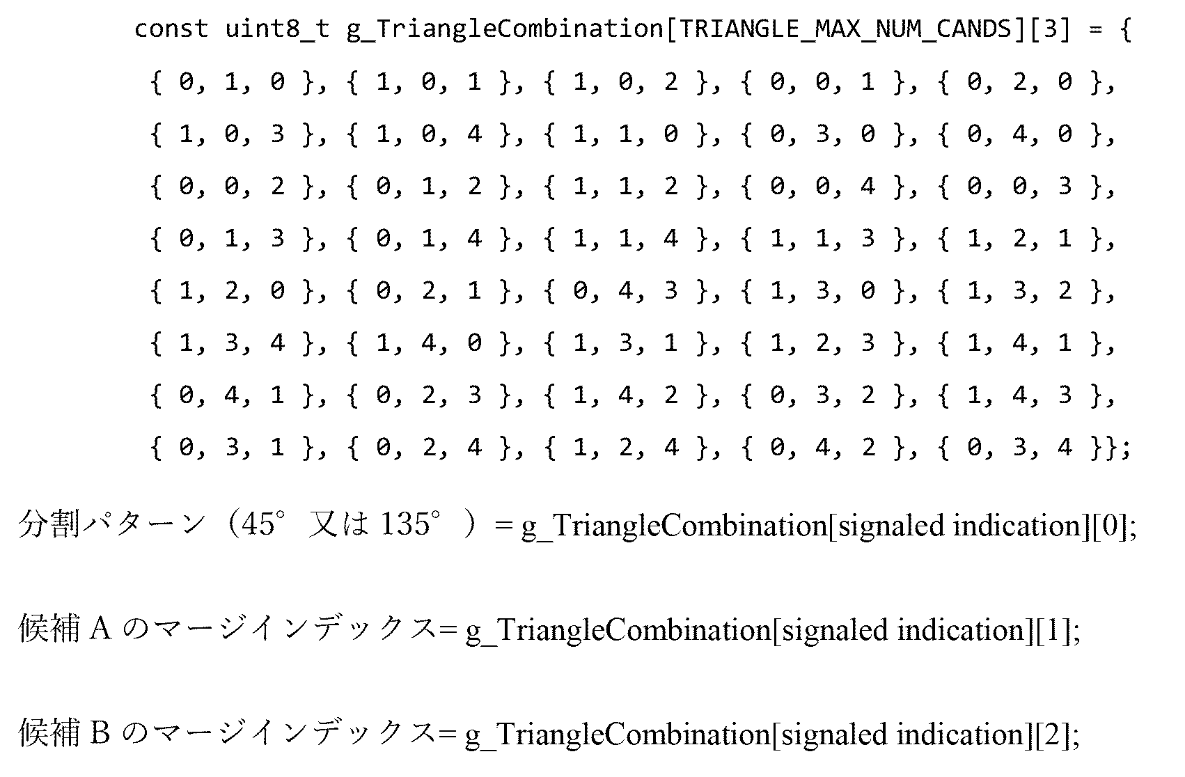
2つの動き候補A及びBが導出されると、2つのパーティション(PU1及びPU2)の動き情報はA又はBのどちらか一方からセットされ得る。PU1がマージ候補A又はBのどちらの動き情報を使用するかは、2つの動き候補の予測方向に依存する。表1は、2つのパーティションについて、2つの導出された動き候補A及びBの間の関係を示す。

2.3.2.3.3.指示(merge_triangle_idxと表される)のエントロピコーディング
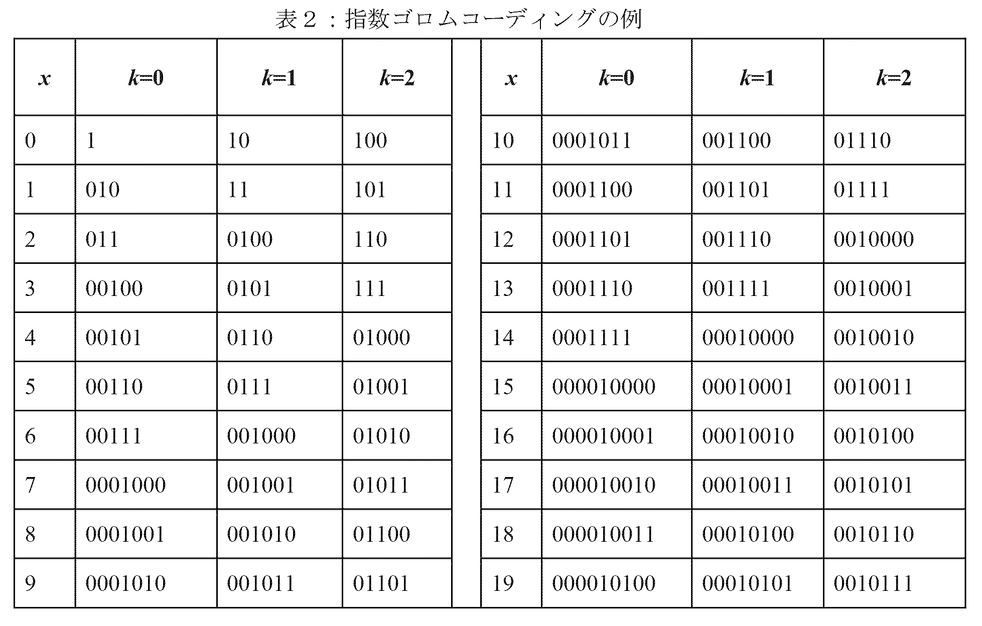
merge_triangle_idxは、0以上39以下の範囲([0,39])内にある。K次の指数ゴロム(Exponential Golomb,EG)コードは、merge_triangle_idxの二値化のために使用される。ここで、Kは1にセットされる。
2.3.2.3.3. Entropy coding of the instruction (denoted as merge_triangle_idx) merge_triangle_idx is in the range from 0 to 39 ([0,39]). A K-order Exponential Golomb (EG) code is used for binarization of merge_triangle_idx. Here, K is set to 1.
K次のEG
(より小さい数をエンコードするためにより多くの数を使用することを犠牲にして)より少ないビットでより大きい数をエンコードするために、これは、非負整数パラメータkを用いて一般化され得る。非負整数xを次数kの指数ゴロムコードでエンコードするために:
1.上記の次数0の指数ゴロムコードを用いて
![]()
2.二進法でxmod2kをエンコードする。
This can be generalized with a non-negative integer parameter k to encode larger numbers with fewer bits (at the expense of using more numbers to encode smaller numbers). To encode a non-negative integer x with an exponential Golomb code of order k:
1. Using the
![]()
2. Encode xmod2k in binary.
2.3.3.アフィン動き補償予測
HEVCでは、並進運動モデル(translation motion model)しか動き補償予測(Motion Compensation Prediction,MCP)のために適用されない。現実世界では、多くの種類の動き、例えば、ズームイン/アウト、回転、射影運動、及び他の不規則な動きを有する可能性がある。VVCでは、簡単化されたアフィン変換動き補償予測が4パラメータアフィンモデル及び6パラメータアフィンモデルにより適用される。図16に示されるように、ブロックのアフィン運動場は、4パラメータアフィンモデルについては2つの制御点動きベクトル(Control Point Motion Vectors,CPMV)、及び6パラメータアフィンモデルについては3つのCPMVによって記述される。
2.3.3. Affine Motion Compensation Prediction In HEVC, only a translation motion model is applied for Motion Compensation Prediction (MCP). The real world can have many types of motion, such as zooming in/out, rotation, projective motion, and other irregular motions. In VVC, simplified affine transform motion compensated prediction is applied with a 4-parameter affine model and a 6-parameter affine model. As shown in FIG. 16, the affine motion field of a block is described by two Control Point Motion Vectors (CPMVs) for the four-parameter affine model and three CPMVs for the six-parameter affine model.
図16は、簡単化されたアフィン運動モデルの例を示す。 FIG. 16 shows an example of a simplified affine motion model.
ブロックの動きベクトル場(Motion Vector Field,MVF)は、式(1)の4パラメータアフィンモデル(ここで、4パラメータは、変数a、b、e及びfとして定義されている。)及び式(2)の6パラメータアフィンモデル(ここで、6パラメータは、a、b、c、d、e及びfとして定義されている。)により夫々、次の式によって記述される:

ここで、(mvh 0,mvh 0)は、左上隅の制御点の動きベクトルであり、(mvh 1,mvh 1)は、右上隅の制御点の動きベクトルであり、(mvh 2,mvh 2)は、左下隅の制御点の動きベクトルであり、これら3つの動きベクトルは全て、制御点動きベクトル(CPMV)と呼ばれ、(x,y)は、現在のブロック内の左上サンプルに対する代表点の座標を表し、(mvh(x,y),mvv(x,y))は、(x,y)に位置しているサンプルについて導出された動きベクトルである。CP動きベクトルは、シグナリング(アフィンAMVPモードと同様)されるか、あるいは、オン・ザ・フライで導出(アフィンモードと同様)されてよい。w及びhは、現在のブロックの幅及び高さである。実際に、分割は、丸め演算付き右シフトによって実施される。VTMでは、代表点は、サブブロックの中心位置であるよう定義され、例えば、現在のブロック内の左上サンプルに対するサブブロックの左上隅の座標が(xs,ys)である場合に、代表点の座標は、(xs+2,ys+2)であるよう定義される。各サブブロック(すなわち、VTMでは4×4)について、代表点は、そのサブブロック全体の動きベクトルを導出するために利用される。 Here, (mv h 0 , mv h 0 ) is the motion vector of the control point in the upper left corner, (mv h 1 , mv h 1 ) is the motion vector of the control point in the upper right corner, and (mv h 2 , mv h 2 ) is the motion vector of the control point in the lower left corner, all these three motion vectors are called control point motion vectors (CPMV), and (x,y) is the motion vector of the control point in the current block. It represents the coordinates of the representative point for the upper left sample, and (mv h (x, y), mv v (x, y)) is the motion vector derived for the sample located at (x, y). The CP motion vector may be signaled (as in affine AMVP mode) or derived on the fly (as in affine mode). w and h are the width and height of the current block. In fact, the division is performed by a right shift with rounding operation. In VTM, the representative point is defined to be the center position of a sub-block, for example, if the coordinates of the upper left corner of the sub-block with respect to the upper left sample in the current block are (xs, ys), then the coordinates of the representative point are is defined to be (xs+2, ys+2). For each sub-block (ie 4x4 in VTM), the representative points are utilized to derive the motion vector for that entire sub-block.
動き補償予測を更に簡単にするために、サブブロックベースのアフィン変換予測が適用される。各M×Nサブブロック(M及びNは両方とも、現在のVVCでは、4にセットされる。)の動きベクトルを導出するために、図17に示される各サブブロックの中心サンプルの動きベクトルは、式(1)及び(2)に従って計算され、1/16分数精度に丸められ得る。次いで、1/16ペルのための動き補償補間フィルタが、導出された動きベクトルにより各サブブロックの予測を生成するために適用される。1/16ペルのための補間フィルタがアフィンモードによって導入される。 To further simplify motion compensated prediction, subblock-based affine transform prediction is applied. To derive the motion vector of each M×N subblock (M and N are both set to 4 in the current VVC), the motion vector of the center sample of each subblock shown in FIG. , may be calculated according to equations (1) and (2) and rounded to 1/16 fractional precision. A motion compensated interpolation filter for 1/16 pel is then applied to generate a prediction for each sub-block with the derived motion vectors. An interpolation filter for 1/16 pel is introduced by affine mode.
MCPの後、各サブブロックの高精度動きベクトルは丸められ、通常の動きベクトルと同じ精度としてセーブされる。 After MCP, the high-precision motion vectors of each sub-block are rounded and saved as the same precision as normal motion vectors.
2.3.3.1.アフィン予測のシグナリング
並進運動モデルと同様に、アフィンモデルによるサイド情報をシグナリングするための2つのモードもある。それらは、AFFINE_INTERモード及びAFFINE_MERGEモードである。
2.3.3.1. Signaling Affine Predictions Similar to the translational motion model, there are also two modes for signaling side information with the affine model. These are AFFINE_INTER mode and AFFINE_MERGE mode.
2.3.3.2.AF_INTERモード
幅及び高さの両方が8よりも大きいCUについては、AF_INTERモードが適用され得る。CUレベルでのアフィンフラグは、AF_INTERモードが使用されるかどうかを示すためにビットストリームでシグナリングされる。
2.3.3.2. AF_INTER Mode For CUs with both width and height greater than 8, AF_INTER mode may be applied. An affine flag at the CU level is signaled in the bitstream to indicate whether AF_INTER mode is used.
このモードで、各参照ピクチャリスト(List0又はList1)について、アフィンAMVP候補リストは、次の順序で3つのタイプのアフィン動き予測子により構成され、各候補は、現在のブロックの推定されたCPMVを含む。エンコーダ側で見つけられた最良のCPMV(例えば、図20のmv0、mv1、mv2)と推定されたCPMVとの差がシグナリングされる。更には、推定されたCPMVが導出されるアフィンAMVP候補のインデックスが更にシグナリングされる。 In this mode, for each reference picture list (List0 or List1), the affine AMVP candidate list is composed of three types of affine motion predictors in the following order, where each candidate calculates the estimated CPMV of the current block. include. The difference between the best CPMV found at the encoder side (eg, mv 0 , mv 1 , mv 2 in FIG. 20) and the estimated CPMV is signaled. Furthermore, the index of the affine AMVP candidate from which the estimated CPMV is derived is further signaled.
1)遺伝的(つまり、引き継がれた(inherited))アフィン動き予測子
検査順序は、HEVC AMVPリスト構成における空間MVPのそれと同様である。最初に、現在のブロックと同じ参照ピクチャを有し、アフィンコーディングされている{A1,A0}内の最初のブロックから、左側の遺伝的アフィン動き予測子が導出される。第2に、現在のブロックと同じ参照ピクチャを有し、アフィンコーディングされている{B1,B0,B2}内の最初のブロックから、上側の遺伝的アフィン動き予測子が導出される。5つのブロックA1、A0、B1、B0、B2は、図19に表されている。
1) Genetic (i.e., inherited) affine motion predictors The testing order is similar to that of the spatial MVP in the HEVC AMVP list structure. First, a left genetic affine motion predictor is derived from the first block in {A1, A0} that has the same reference picture as the current block and is affine coded. Second, the upper genetic affine motion predictor is derived from the first block in {B1, B0, B2} that has the same reference picture as the current block and is affine coded. Five blocks A1, A0, B1, B0, B2 are represented in FIG.
隣接するブロックがアフィンモードでコーディングされていると分かると、隣接するブロックをカバーするコーディングユニットのCPMVは、現在のブロックのCPMVの予測子を導出するために使用される。例えば、A1が非アフィンモードでコーディングされ、A0が4パラメータアフィンモードでコーディングされる場合に、左側の遺伝的アフィンMV予測子はA0から導出されることになる。この場合に、図21Bで左上CPMVについてはMV0 N及び右上CPMVについてはMV1 Nによって表されている、A0をカバーするCUのCPMVは、現在のブロックの左上位置(座標(x0,y0)を有する)、右上位置(座標(x1,y1)を有する)及び右下位置(座標(x2,y2)を有する)についてMV0 C、MV1 C、MV2 Cによって表される現在のブロックの推定されたCPMVを導出するために利用される。 Once a neighboring block is found to be coded in affine mode, the CPMV of the coding unit covering the neighboring block is used to derive a predictor of the CPMV of the current block. For example, if A1 is coded in a non-affine mode and A0 is coded in a four-parameter affine mode, the left genetic affine MV predictor will be derived from A0. In this case, the CPMV of the CU covering A0, represented by MV 0 N for the upper left CPMV and MV 1 N for the upper right CPMV in FIG. 21B, is the upper left position of the current block (coordinates (x0, y0) of the current block represented by MV 0 C , MV 1 C , MV 2 C for the top right position (having coordinates (x1, y1)) and the bottom right position (having coordinates (x2, y2)) It is used to derive the estimated CPMV.
2)構成されたアフィン動き予測子
構成されたアフィン動き予測子は、同じ参照ピクチャを有している、図20に示されるような隣接するインターコーディングされたブロックから導出される制御点動きベクトル(CPMV)から成る。現在のアフィン運動モデルが4パラメータアフィンである場合に、CPMVの数は2であり、そうではなく、現在のアフィン運動モデルが6パラメータアフィンである場合に、CPMVの数は3である。左上CPMV
(外1)
![]()
(外2)
![]()
(外3)
![]()
- 現在のアフィン運動モデルが4パラメータアフィンである場合に、構成されたアフィン動き予測子は、バーmv0及びバーmv1の両方が求められる、つまり、バーmv0及びバーmv1が現在のブロックの左上位置(座標(x0,y0)を有する)及び右上位置(座標(x1,y1)を有する)についての推定されたCPMVとして使用される場合にのみ、候補リストに挿入される。
- 現在のアフィン運動モデルが6パラメータアフィンである場合に、構成されたアフィン動き予測子は、バーmv0、バーmv1、及びバーmv2が全て求められる、つまり、バーmv0、バーmv1、及びバーmv2が現在のブロックの左上位置(座標(x0,y0)を有する)、右上位置(座標(x1,y1)を有する)及び右下位置(座標(x2,y2)を有する)についての推定されたCPMVとして使用される場合にのみ、候補リストに挿入される。
2) Constructed Affine Motion Predictor A constructed affine motion predictor consists of control point motion vectors ( CPMV). If the current affine motion model is a 4-parameter affine, the number of CPMVs is 2; otherwise, if the current affine motion model is a 6-parameter affine, the number of CPMVs is 3. Upper left CPMV
(Outside 1)
![]()
(Outside 2)
![]()
(Outer 3)
![]()
- If the current affine motion model is a four-parameter affine, the constructed affine motion predictor is determined for both bar mv 0 and bar mv 1 , i.e. bar mv 0 and bar mv 1 are the current block is inserted into the candidate list only if it is used as the estimated CPMV for the upper left position (with coordinates (x0, y0)) and upper right position (with coordinates (x1, y1)).
- If the current affine motion model is a 6-parameter affine, the constructed affine motion predictor is such that bar mv 0 , bar mv 1 , and bar mv 2 are all determined, i.e. bar mv 0 , bar mv 1 , and bar mv 2 for the top left position (with coordinates (x0, y0)), top right position (with coordinates (x1, y1)) and bottom right position (with coordinates (x2, y2)) of the current block. is inserted into the candidate list only if it is used as the estimated CPMV of
構成されたアフィン動き予測子を候補リストに挿入する場合に、プルーニングプロセスは適用されない。 No pruning process is applied when inserting the constructed affine motion predictor into the candidate list.
3)通常のAMVP動き予測子
以下は、アフィン動き予測の数が最大値に達するまで適用される。
1)利用可能である場合に全てのCPMVをバーmv2に等しくセットすることによってアフィン動き予測子を導出する。
2)利用可能である場合に全てのCPMVをバーmv1に等しくセットすることによってアフィン動き予測子を導出する。
3)利用可能である場合に全てのCPMVをバーmv0に等しくセットすることによってアフィン動き予測子を導出する。
4)利用可能である場合に全てのCPMVをHEVC TMVPに等しくセットすることによってアフィン動き予測子を導出する。
5)全てのCPMVをゼロMVにセットすることによってアフィン動き予測子を導出する。
3) Regular AMVP motion predictor The following is applied until the number of affine motion predictions reaches a maximum value.
1) Derive an affine motion predictor by setting all CPMVs equal to mv2 if available.
2) Derive an affine motion predictor by setting all CPMVs equal to mv 1 if available.
3) Derive the affine motion predictor by setting all CPMVs equal to mv 0 if available.
4) Derive the affine motion predictor by setting all CPMVs equal to the HEVC TMVP if available.
5) Derive the affine motion predictor by setting all CPMVs to zero MV.
留意されるべきは、
(外4)
![]()
(outer 4)
![]()
AF_INTERモードでは、4又は6パラメータアフィンモードが使用される場合に、2又は3つの制御点が必要とされるので、2つ又は3つのMVDが、図18に示されるように、それらの制御点に対してコーディングされる必要がある。JVET-K0337では、MVを次のように導出することが提案されており、すなわち、mvd0からmvd1及びmvd2が予測される。

ここで、バーmvi、mvdi及びmviは、図18(b)に示されるように、夫々、左上ピクセル(i=0)、右上ピクセル(i=1)、又は左下ピクセル(i=2)の予測された動きベクトル、動きベクトル差分及び動きベクトルである。2つの動きベクトル(例えば、mvA(xA,yA)及びmvB(xB,yB))の追加は、別々に2つの成分の和に等しいことに留意されたい。すなわち、newMV=mvA+mvBであり、newMVの2つの成分は夫々、(xA+xB)及び(yA+yB)にセットされる。 Here, the bars mv i , mvd i and mv i are respectively the upper left pixel (i=0), the upper right pixel (i=1), or the lower left pixel (i=2 ), the predicted motion vector, the motion vector difference, and the motion vector. Note that the addition of two motion vectors (eg, mvA(xA, yA) and mvB(xB, yB)) is equal to the sum of the two components separately. That is, newMV=mvA+mvB, and the two components of newMV are set to (xA+xB) and (yA+yB), respectively.
2.3.3.3.AF_MERGEモード
CUがAF_MERGEモードで適用される場合に、それは、有効な隣接する再構成されたブロックからアフィンモードによりコーディングされた最初のブロックを得る。そして、候補ブロックの選択順序は、図21(a)に示されるように、左から、上、右上、左下、左上へである(順にA、B、C、D、Eによって表される)。例えば、隣接する左下ブロックが、図21(b)でA0によって表されるように、アフィンモードでコーディングされる場合に、ブロックAを含む隣接するCU/PUの左上隅、右上隅、及び左下隅の制御点(CP)動きベクトルmv0
N、mv1
N及びmv2
Nがフェッチされる。そして、現在のCU/PU上の左上隅/右上/左下の動きベクトルmv0
C、mv1
C及びmv2
C(6パラメータアフィンモデルのためにのみ使用される)は、mv0
N、mv1
N及びmv2
Nに基づいて計算される。留意されるべきは、VTM-2.0では、現在のブロックがアフィンコーディングされている場合に、左上隅に位置するサブブロック(例えば、VTMでは、4×4ブロック)は、mv0を保存し、右上隅にあるサブブロックは、mv1を保存する。現在のブロックが6パラメータアフィンモデルでコーディングされる場合には、左下隅にあるサブブロックは、mv2を保存し、そうでない(4パラメータアフィンモデルによる)場合には、LBはmv2’を保存する。他のサブブロックは、MCのために使用されるMVを保存する。
2.3.3.3. AF_MERGE Mode When the CU is applied in AF_MERGE mode, it obtains the first block coded by affine mode from valid neighboring reconstructed blocks. The selection order of candidate blocks is from left to top, top right, bottom left, and top left (represented by A, B, C, D, and E in this order), as shown in FIG. 21(a). For example, if the adjacent lower left block is coded in affine mode, as represented by A0 in FIG. 21(b), the upper left corner, upper right corner, and lower left corner of the adjacent CU/PU containing block The control point (CP) motion vectors mv 0 N , mv 1 N and mv 2 N of are fetched. And the motion vectors mv 0 C , mv 1 C and mv 2 C (used only for the 6-parameter affine model) of the upper left corner/upper right/lower left on the current CU/PU are mv 0 N , mv 1 N and mv 2 N. It should be noted that in VTM-2.0, if the current block is affine coded, the sub-block located at the top left corner (e.g. 4x4 block in VTM) preserves mv0; The subblock in the upper right corner stores mv1. If the current block is coded with a 6-parameter affine model, the sub-block in the lower left corner stores mv2; otherwise (according to the 4-parameter affine model), the LB stores mv2'. Other subblocks store MVs used for MC.
現在のCUのCPMVであるmv0 C、Mv1 C及びmv2 Cが、簡単化されたアフィン運動モデル、つまり、式(1)及び(2)に従って導出された後、現在のCUのMVFが生成される。現在のCUがAF_MERGEモードでコーディングされているかどうかを識別するために、アフィンモードでコーディングされている少なくとも1つの隣接ブロックがある場合に、アフィンフラグがビットストリームでシグナリングされる。 After the CPMVs of the current CU, mv 0 C , Mv 1 C and mv 2 C , are derived according to the simplified affine motion model, i.e., equations (1) and (2), the MVF of the current CU is generated. To identify whether the current CU is coded in AF_MERGE mode, an affine flag is signaled in the bitstream if there is at least one neighboring block coded in affine mode.
JVET-L0142及びJVET-L0632では、アフィンマージ候補リストは、次のステップで構成される。 In JVET-L0142 and JVET-L0632, the affine merge candidate list is constructed in the following steps.
1)遺伝的アフィン候補の挿入
遺伝によるアフィン候補(inherited affine candidate)とは、候補が、その有効な隣接するアフィンコーディングされたブロックのアフィン運動モデルから導出されることを意味する。最大2つの遺伝的アフィン候補が、隣接ブロックのアフィン運動モデルから導出され、候補リストに挿入される。左側予測子については、走査順序は{A0,A1}であり、上側予測子については、走査順序は{B0,B1,B2}である。
1) Insertion of a genetic affine candidate Inherited affine candidate means that the candidate is derived from the affine motion model of its valid neighboring affine coded blocks. Up to two genetic affine candidates are derived from the affine motion model of neighboring blocks and inserted into the candidate list. For the left predictor, the scan order is {A0, A1}, and for the top predictor, the scan order is {B0, B1, B2}.
2)構成されたアフィン候補の挿入
アフィンマージ候補リスト内の候補の数がMaxNumAffineCand(例えば、5つ)に満たない場合には、構成されたアフィン候補(constructed affine candidates)が候補リストに挿入される。構成されたアフィン候補とは、候補が、各制御点の隣接動き情報を結合することによって構成されることを意味する。
a)制御点の動き情報は、最初に、図22に示されている指定された空間近傍及び時間近傍から導出される。CPk(k=1,2,3,4)は、k番目の制御点を表す。A0、A1、A2、B0、B1、B2及びB3は、CPk(k=1,2,3)を予測するための空間的位置である。Tは、CP4を予測するための時間的位置である。
CP1、CP2、CP3及びCP4の座標は、夫々、(0,0)、(W,0)、(H,0)及び(W,H)であり、ここで、W及びHは、現在のブロックの幅及び高さである。
各制御点の動き情報は、次の優先順序に従って取得される:
- CP1については、チェック優先度はB2→B3→A2である。B2は、それが利用可能である場合に使用される。そうではない場合に、B3が利用可能であるならば、B3が使用される。B2及びB3の両方が利用不可能である場合には、A2が使用される。3つ全ての候補が利用不可能である場合には、CP1の動き情報は取得不可能である。
- CP2については、チェック優先度はB1→B0である。
- CP3については、チェック優先度はA1→A0である。
- CP4については、Tが使用される。
b)第2に、制御点の組み合わせが、アフィンマージ候補を構成するために使用される。
I.3つの制御点の動き情報が、6パラメータアフィン候補を構成するために必要とされる。3つの制御点は、次の4つの組み合わせ({CP1,CP2,CP4},{CP1,CP2,CP3},{CP2,CP3,CP4},{CP1,CP3,CP4})のうちの1つから選択され得る。組み合わせ{CP1,CP2,CP3}、{CP2,CP3,CP4}、{CP1,CP3,CP4}は、左上、右上、及び左下制御点によって表される6パラメータ運動モデルへ変換されることになる。
II.2つの制御点の動きベクトルが、4パラメータアフィン候補を構成するために必要とされる。2つの制御点は、次の2つの組み合わせ({CP1,CP2},{CP1,CP3})のうちの1つから選択され得る。2つの組み合わせは、左上及び右上制御点によって表される4パラメータ運動モデルへ変換されることになる。
III.構成されたアフィン候補の組み合わせは、次の順序:{CP1,CP2,CP3},{CP1,CP2,CP4},{CP1,CP3,CP4},{CP2,CP3,CP4},{CP1,CP2},{CP1,CP3}として候補リストに挿入される。
i.組み合わせごとに、各CPのためのリストXの参照インデックスはチェックされ、それらが全て同じである場合に、この組み合わせはリストXの有効なCPMVを有している。組み合わせがリスト0及びリスト1の両方の有効なCPMVを有してない場合には、この組み合わせは無効とマークされる。そうでない場合には、それは有効であり、CPMVはサブブロックマージリストに置かれる。
2) Insertion of constructed affine candidates If the number of candidates in the affine merge candidate list is less than MaxNumAffineCand (for example, 5), constructed affine candidates are inserted into the candidate list. . A constructed affine candidate means that the candidate is constructed by combining adjacent motion information of each control point.
a) Motion information for a control point is first derived from the specified spatial and temporal neighborhoods shown in FIG. CPk (k=1, 2, 3, 4) represents the k-th control point. A0, A1, A2, B0, B1, B2 and B3 are spatial locations for predicting CPk (k=1, 2, 3). T is the temporal position for predicting CP4.
The coordinates of CP1, CP2, CP3 and CP4 are (0,0), (W,0), (H,0) and (W,H), respectively, where W and H are the current block The width and height of
Motion information for each control point is obtained according to the following priority order:
- For CP1, the check priority is B2→B3→A2. B2 is used if it is available. Otherwise, if B3 is available, B3 is used. If both B2 and B3 are unavailable, A2 is used. If all three candidates are unavailable, motion information for CP1 cannot be obtained.
- For CP2, the check priority is B1→B0.
- For CP3, the check priority is A1→A0.
- For CP4, T is used.
b) Second, a combination of control points is used to construct affine merge candidates.
I. Motion information of three control points is required to construct a 6-parameter affine candidate. The three control points are selected from one of the following four combinations ({CP1, CP2, CP4}, {CP1, CP2, CP3}, {CP2, CP3, CP4}, {CP1, CP3, CP4}) can be selected. The combinations {CP1, CP2, CP3}, {CP2, CP3, CP4}, {CP1, CP3, CP4} will be transformed into a 6-parameter motion model represented by the upper left, upper right, and lower left control points.
II. Two control point motion vectors are required to construct a four-parameter affine candidate. The two control points may be selected from one of the following two combinations ({CP1, CP2}, {CP1, CP3}). The combination of the two will be transformed into a four-parameter kinematic model represented by the upper left and upper right control points.
III. The configured combinations of affine candidates are in the following order: {CP1, CP2, CP3}, {CP1, CP2, CP4}, {CP1, CP3, CP4}, {CP2, CP3, CP4}, {CP1, CP2} , {CP1, CP3} into the candidate list.
i. For each combination, the reference indices of list X for each CP are checked, and if they are all the same, this combination has a valid CPMV of list X. If a combination does not have valid CPMVs in both
3)ゼロアフィン動きベクトル候補によるパディング
アフィンマージ候補リスト内の候補の数が5よりも少ない場合に、サブブロックマージ候補リストについて、4パラメータマージ候補は、MVが(0,0)にセットされ、予測方向がリスト0からの片予測(Pスライスの場合)及び双予測(Bスライスの場合)にセットされる。
3) Padding with zero-affine motion vector candidates When the number of candidates in the affine merge candidate list is less than 5, for the sub-block merge candidate list, the 4-parameter merge candidates have MV set to (0,0) and the prediction The direction is set to uni-prediction (for P slices) and bi-prediction (for B slices) from
2.3.4.VVCにおけるマージリスト設計
VVCでサポートされている3つの異なったマージリスト構成プロセスがある。
1)サブブロックマージ候補リスト:それはATMVP及びアフィンマージ候補を含む。1つのマージリスト構成プロセスが、アフィンモード及びATMVPモードの両方について共有される。ここで、ATMVP及びアフィンマージ候補は順番に加えられ得る。サブブロックマージリストのサイズはスライスヘッダでシグナリングされ、最大値は5である。
2)片予測TPMマージリスト:三角予測モードについては、2つのパーティションがそれら自身のマージ候補インデックスを選択することができたとしても、2つのパーティションのための1つのマージリスト構成プロセスが共有される。このマージリストを構成するときに、ブロックの空間隣接ブロック及び2つの時間ブロックがチェックされる。空間近傍及び時間ブロックから導出された動き情報は、我々のIDFでは正則動き候補と呼ばれる。これらの正則動き候補は、複数のTPM航法を導出するために更に利用される。2つのパーティションがそれら自身の予測ブロックを生成するために異なる動きベクトルを使用し得るとしても、ブロック全体のレベルで変換が実行されることに留意されたい。
片予測TPMマージリストサイズは、5であるよう固定される。
3)正則マージリスト:残りのコーディングブロックについては、1つのマージリスト構成プロセスが共有される。ここで、空間/時間/HMVP、ペアワイズの組み合わされた双予測マージ候補、及びゼロ動き候補は、順番に挿入され得る。正則マージリストのサイズはスライスヘッダでシグナリングされ、最大値は6である。
2.3.4. Merge List Design in VVC There are three different merge list construction processes supported in VVC.
1) Sub-block merge candidate list: It includes ATMVP and affine merge candidates. One merge list configuration process is shared for both affine and ATMVP modes. Here, ATMVP and affine merge candidates may be added in order. The size of the subblock merge list is signaled in the slice header, and the maximum value is 5.
2) Unipredictive TPM merge list: For triangular prediction mode, one merge list construction process for the two partitions is shared, even though the two partitions can choose their own merge candidate indexes. . When constructing this merge list, a block's spatial neighbors and two temporal blocks are checked. The motion information derived from spatial neighborhoods and temporal blocks is called regular motion candidates in our IDF. These regular motion candidates are further utilized to derive multiple TPM navigations. Note that the transformation is performed at the level of the whole block, even though the two partitions may use different motion vectors to generate their own predictive blocks.
The single prediction TPM merge list size is fixed to be 5.
3) Canonical merge list: One merge list construction process is shared for the remaining coding blocks. Here, the spatial/temporal/HMVP, pairwise combined bi-predictive merge candidates, and zero motion candidates may be inserted in order. The size of the canonical merge list is signaled in the slice header, and the maximum value is 6.
2.3.4.1.サブブロックマージ候補リスト
全てのサブブロックに関連した動き候補は、非サブブロックマージ候補のための正則マージリストに加えて別個のマージリストに置かれる。
2.3.4.1. Subblock Merge Candidate List The motion candidates associated with all subblocks are placed in a separate merge list in addition to the canonical merge list for non-subblock merge candidates.
サブブロックに関連した動き候補は、「サブブロックマージ候補リスト」と名付けられている別個のマージリストに置かれる。 The motion candidates associated with the sub-block are placed in a separate merge list named "sub-block merge candidate list".
一例で、サブブロックマージ候補リストは、アフィンマージ候補、及びATMVP候補、及び/又はサブブロックベースのSTMVP候補を含む。 In one example, the sub-block merging candidate list includes affine merging candidates, ATMVP candidates, and/or sub-block-based STMVP candidates.
2.3.4.1.1.JVET-L0278
この寄稿では、通常のマージリスト内のATMVPマージ候補は、アフィンマージリストの第1の位置に動かされる。それにより、新しいリスト(すなわち、サブブロックベースのマージ候補リスト)内の全てのマージ候補は、サブブロックコーディングツールに基づく。
2.3.4.1.1. JVET-L0278
In this contribution, ATMVP merge candidates in the regular merge list are moved to the first position in the affine merge list. Thereby, all merging candidates in the new list (i.e., sub-block based merging candidate list) are based on the sub-block coding tool.
2.3.4.1.2.JVET-N1001におけるATMVP
ATMVPは、サブブロックベースの時間動きベクトル予測(SbTMVP)としても知られている。
2.3.4.1.2. ATMVP in JVET-N1001
ATMVP is also known as sub-block-based temporal motion vector prediction (SbTMVP).
JVET-N1001では、サブブロックマージ候補リスト(別名、アフィンマージ候補リスト)として知られている特別なマージ候補リストが、正則マージ候補リストに加えて追加されている。サブブロックマージ候補リストは、次の順序で候補を充てんされる:
a.ATMVP候補(利用可能あっても利用不可能であってもよい);
b.遺伝的アフィン候補;
c.同一位置参照ピクチャでのMVを使用するTMVPに基づいた構成されたアフィン候補を含む構成されたアフィン候補;
d.ゼロMVとして4パラメータアフィンモデルをパディングする。
In JVET-N1001, a special merge candidate list known as a subblock merge candidate list (also known as an affine merge candidate list) is added in addition to the canonical merge candidate list. The sub-block merge candidate list is filled with candidates in the following order:
a. ATM VP candidate (may or may not be available);
b. Genetic affine candidates;
c. constructed affine candidates, including constructed affine candidates based on TMVP using MVs with co-located reference pictures;
d. Pad the 4-parameter affine model as zero MV.
VTMは、サブブロックベースの時間動きベクトル予測(sbTMVP)方法をサポートする。HEVCでの時間動きベクトル予測(TMVP)と同様に、SbTMVPは、現在のピクチャにおけるCUのための動きベクトル予測及びマージモードを改善するよう同一位置ピクチャにおける動き場を使用する。TMVPによって使用される同じ同一位置ピクチャはSbTMVPのために使用される。sbTMVPは、次の2つの側面でTMVPとは異なっている:
1.TMVPは、CUレベルで動きを予測するが、sbTMVPは、サブCUレベルで動きを予測する。
2.TMVPは、同一位置ピクチャ内の同一位置ブロック(同一位置ブロックは、現在のCuに対する右下又は中心ブロックである)から時間動きベクトルをフェッチするが、一方で、sbTMVPは、同一位置ピクチャから時間動き情報をフェッチする前に、動きシフトを適用し、動きシフトは、現在のCUの空間隣接ブロックの1つからの動きベクトルから取得される。
VTM supports sub-block-based temporal motion vector prediction (sbTMVP) methods. Similar to temporal motion vector prediction (TMVP) in HEVC, SbTMVP uses the motion field in the co-located picture to improve the motion vector prediction and merge mode for the CU in the current picture. The same co-located pictures used by TMVP are used for SbTMVP. sbTMVP differs from TMVP in two aspects:
1. TMVP predicts motion at the CU level, while sbTMVP predicts motion at the sub-CU level.
2. TMVP fetches the temporal motion vector from the co-located block within the co-located picture (the co-located block is the bottom right or center block for the current Cu), whereas sbTMVP fetches the temporal motion vector from the co-located picture. Before fetching the information, apply a motion shift, which is obtained from the motion vector from one of the spatial neighboring blocks of the current CU.
SbTVMPプロセスは、図23及び図24に表されている。sbTMVPは、2つのステップで現在のCU内のサブCUの動きベクトルを予測する。第1のステップで、図23の空間近傍A1が試験される。A1が、その参照ピクチャとして同一位置ピクチャを使用する動きベクトルを有する場合に、動きベクトルは、適用されるべき動きシフトであるよう選択される。そのような動きが識別されない場合には、動きシフトは(0,0)にセットされる。 The SbTVMP process is depicted in FIGS. 23 and 24. sbTMVP predicts motion vectors of sub-CUs within the current CU in two steps. In the first step, the spatial neighborhood A1 of FIG. 23 is tested. If A1 has a motion vector that uses the co-located picture as its reference picture, then the motion vector is selected to be the motion shift to be applied. If no such motion is identified, the motion shift is set to (0,0).
第2のステップで、ステップ1で識別された動きシフトは、図24に示されるように同一位置ピクチャからサブCUレベルの動き情報(動きベクトル及び参照インデックス)を取得するために適用される(すなわち、現在のブロックの座標に加えられる)。図24の例は、動きシフトがブロックA1の動きにセットされる、と仮定する。それから、サブCUごとに、同一位置ピクチャ内のその対応するブロック(中心サンプルをカバーする最小の動きグリッド)の動き情報は、そのサブCUの動き情報を導出するために使用される。同一位置サブCUの動き情報が識別された後、それは、HEVCのTMVPプロセスと同様にして、現在のサブCUの動きベクトル及び参照インデックスに変換され、ここで、時間動きスケーリングが、時間動きベクトルの参照ピクチャを現在CUのそれらにアライメントするよう適用される。
In the second step, the motion shifts identified in
VTMでは、sbTMVP候補及びアフィンマージ候補の両方を含む、サブブロックベースの複合的なマージリストが、サブブロックベースのマージモードのシグナリングのために使用される。sbTMVPモードは、シーケンスパラメータセット(SPS)フラグによって有効/無効にされる。sbTMVPモードが有効にされる場合に、sbTMVP予測子が、サブブロックベースのマージ候補のリストの最初のエントリとして加えられ、それにアフィンマージ候補が続く。サブブロックベースのマージリストのサイズはSPSでシグナリングされ、サブブロックベースのマージリストの最大許容サイズはVTM4では5である。 In VTM, a subblock-based composite merge list that includes both sbTMVP candidates and affine merge candidates is used for subblock-based merge mode signaling. sbTMVP mode is enabled/disabled by the Sequence Parameter Set (SPS) flag. When sbTMVP mode is enabled, the sbTMVP predictor is added as the first entry in the list of subblock-based merge candidates, followed by affine merge candidates. The size of the sub-block based merge list is signaled in SPS and the maximum allowed size of the sub-block based merge list is 5 in VTM4.
sbTMVPで使用されるサブCUサイズは、8×8である用固定され、アフィンマージモードに対して行われるように、sbTMVPモードは、幅及び高さの両方が8以上であるCUにのみ適用可能である。 The sub-CU size used in sbTMVP is fixed to be 8x8, and sbTMVP mode is only applicable to CUs whose width and height are both greater than or equal to 8, as is done for affine merge mode. It is.
追加のsbTMVPマージ候補の符号化ロジックは、他のマージ候補についてと同じであり、つまり、P又はBスライスにおける各CUについて、追加のRDチェックが、sbTMVP候補を使用すべきかどうかを決定するために実行される。 The encoding logic for additional sbTMVP merge candidates is the same as for other merge candidates, i.e. for each CU in a P or B slice, an additional RD check is performed to determine whether the sbTMVP candidate should be used. executed.
図23~24は、VVCにおけるsbTMVPプロセスの例を示す。 23-24 illustrate an example of the sbTMVP process in VVC.
サブブロックマージ候補リスト内の候補の最大数は、MaxNumSubblockMergeCandと表される。 The maximum number of candidates in the subblock merge candidate list is denoted as MaxNumSubblockMergeCand.
2.3.4.1.3.サブブロックマージリストに関連したシンタックス/セマンティクス
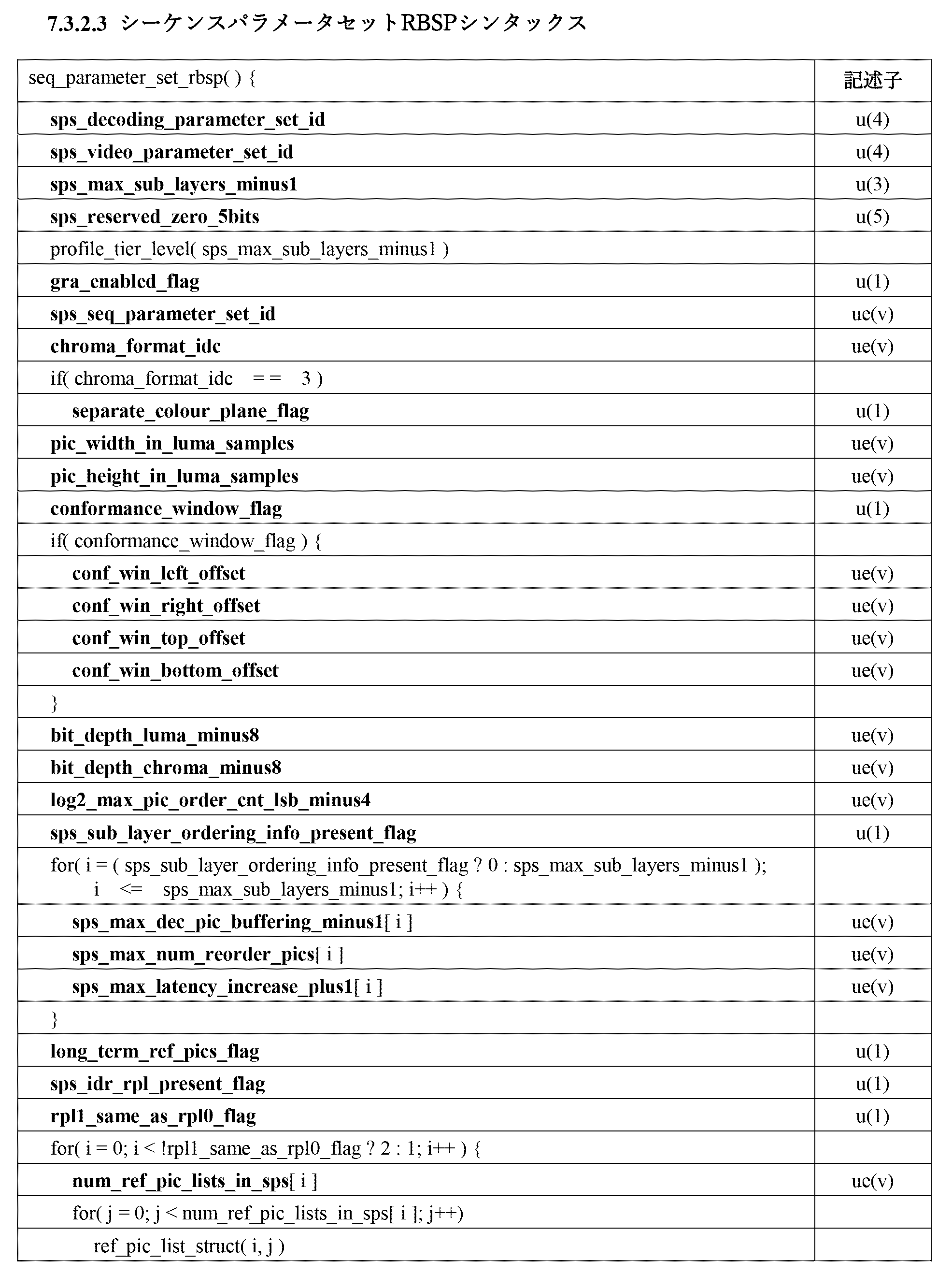
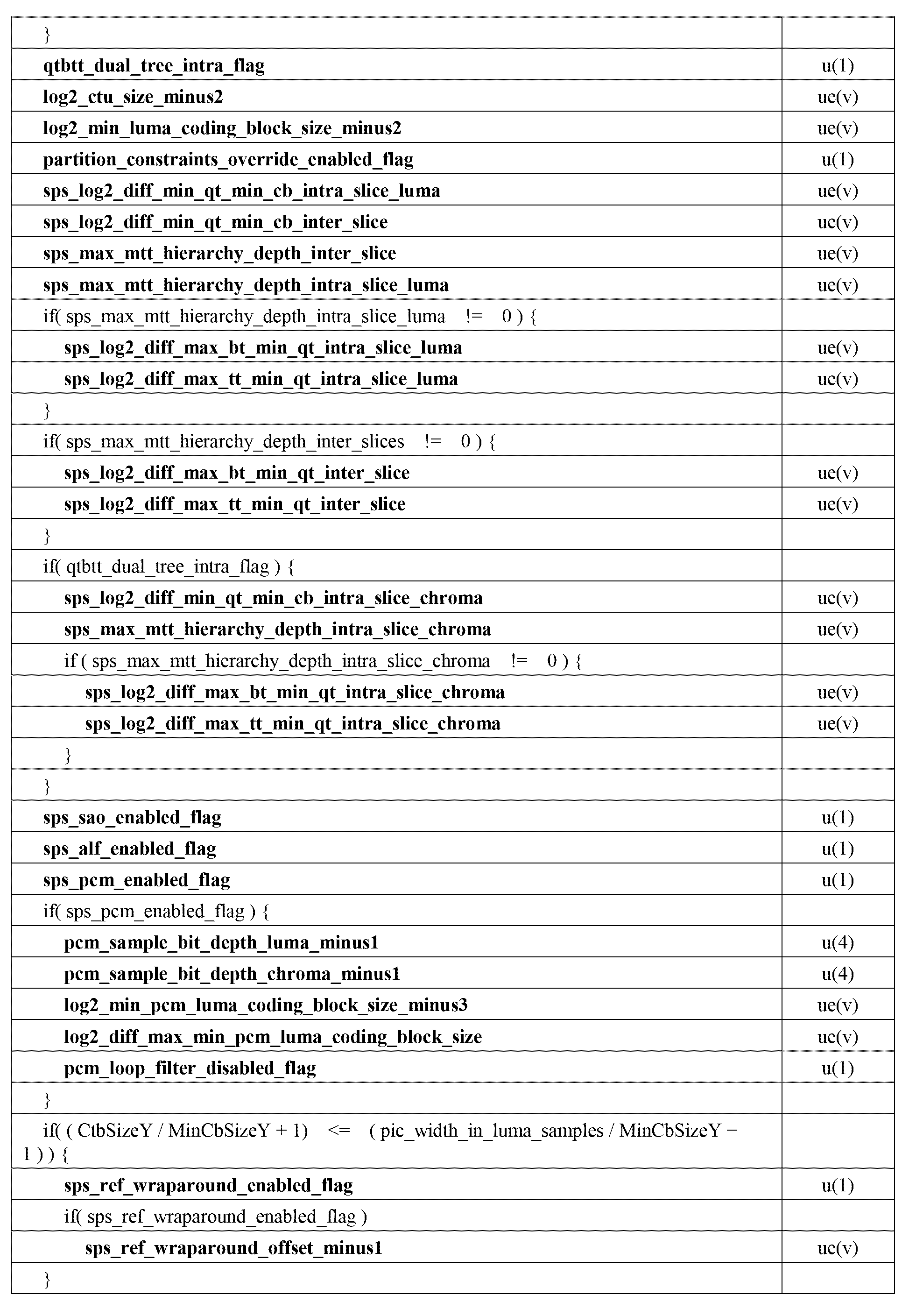
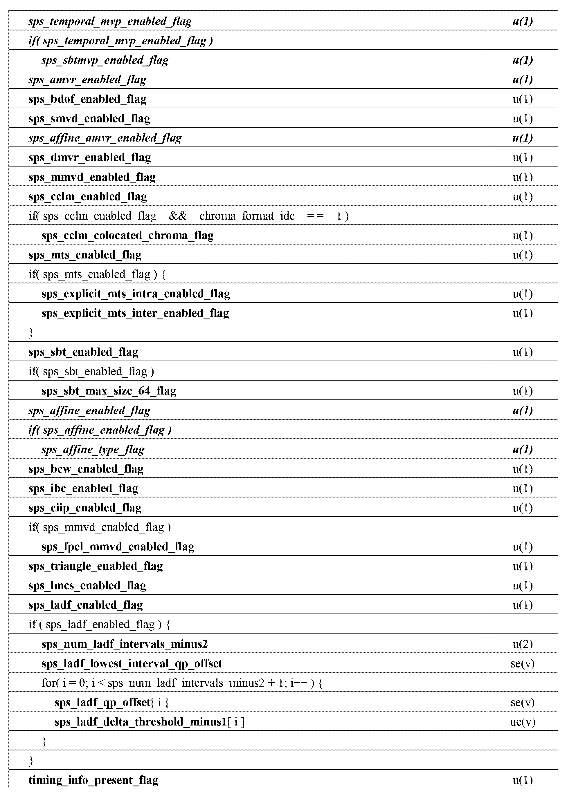
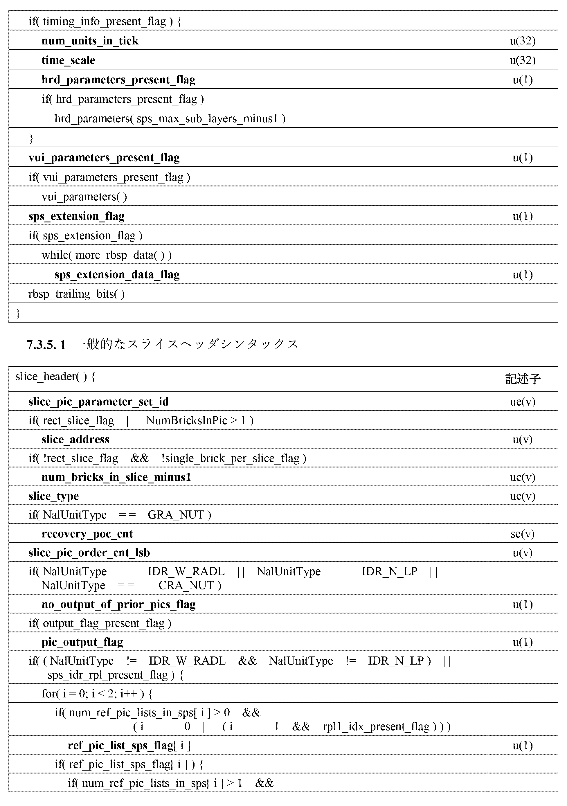
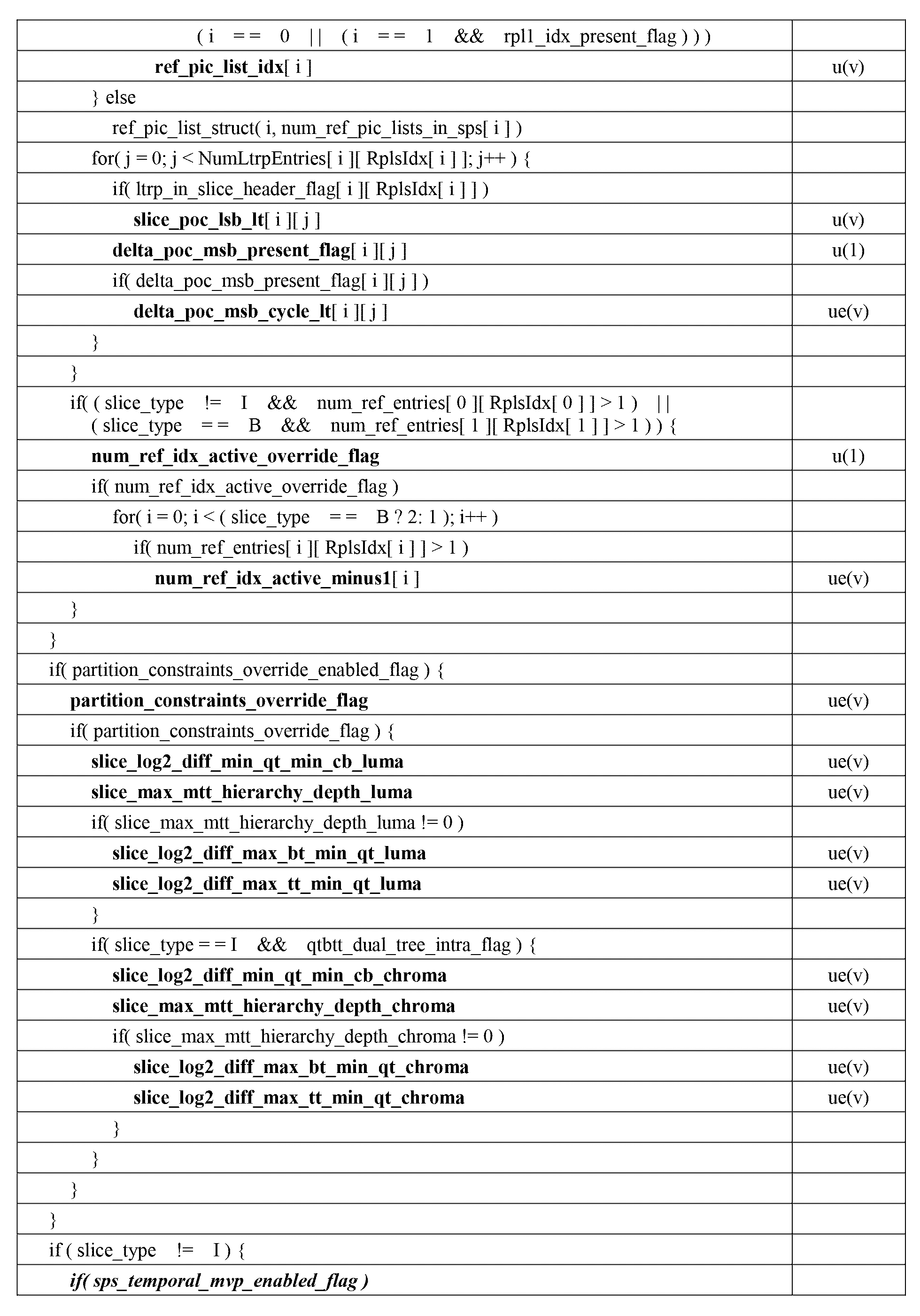
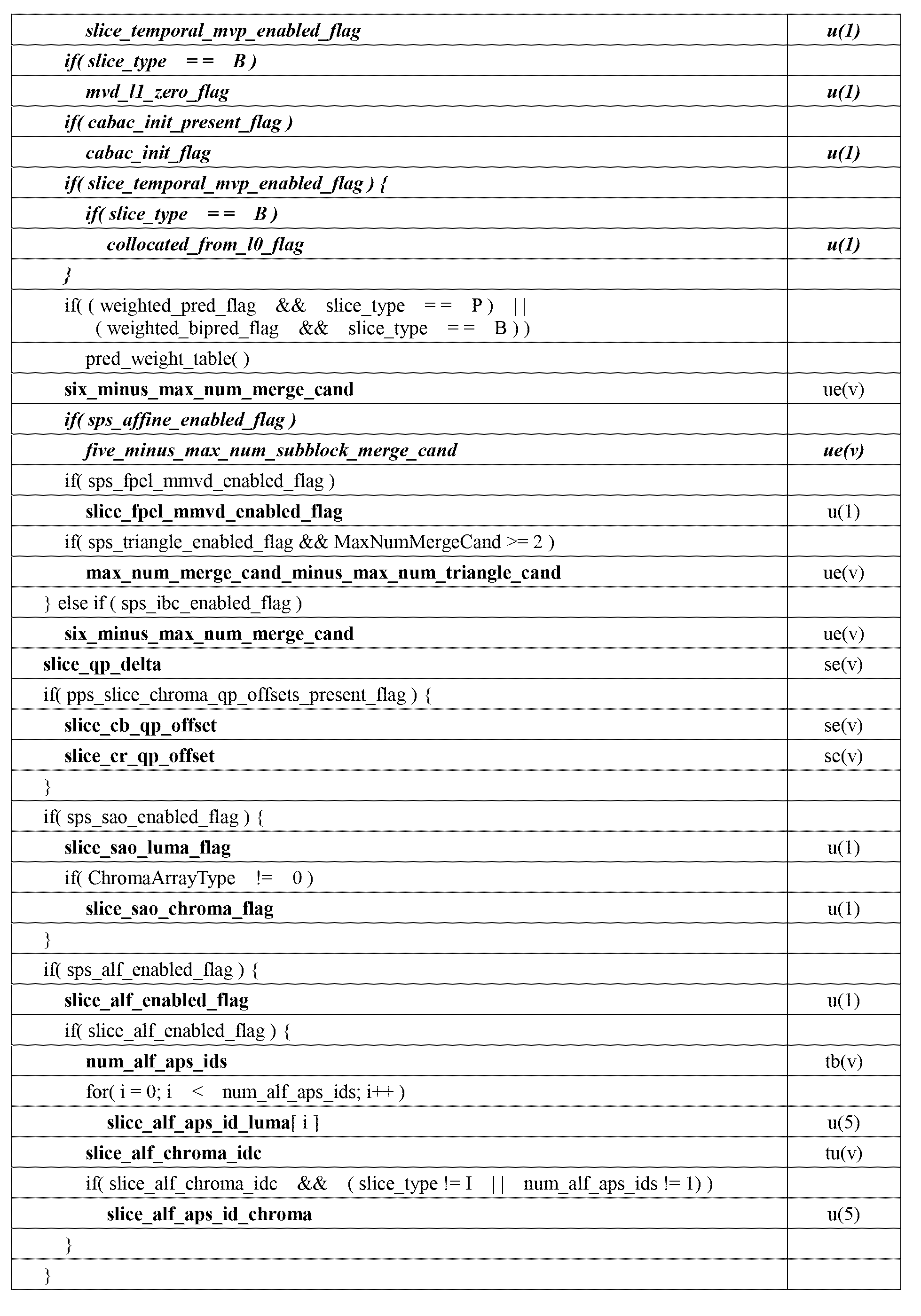
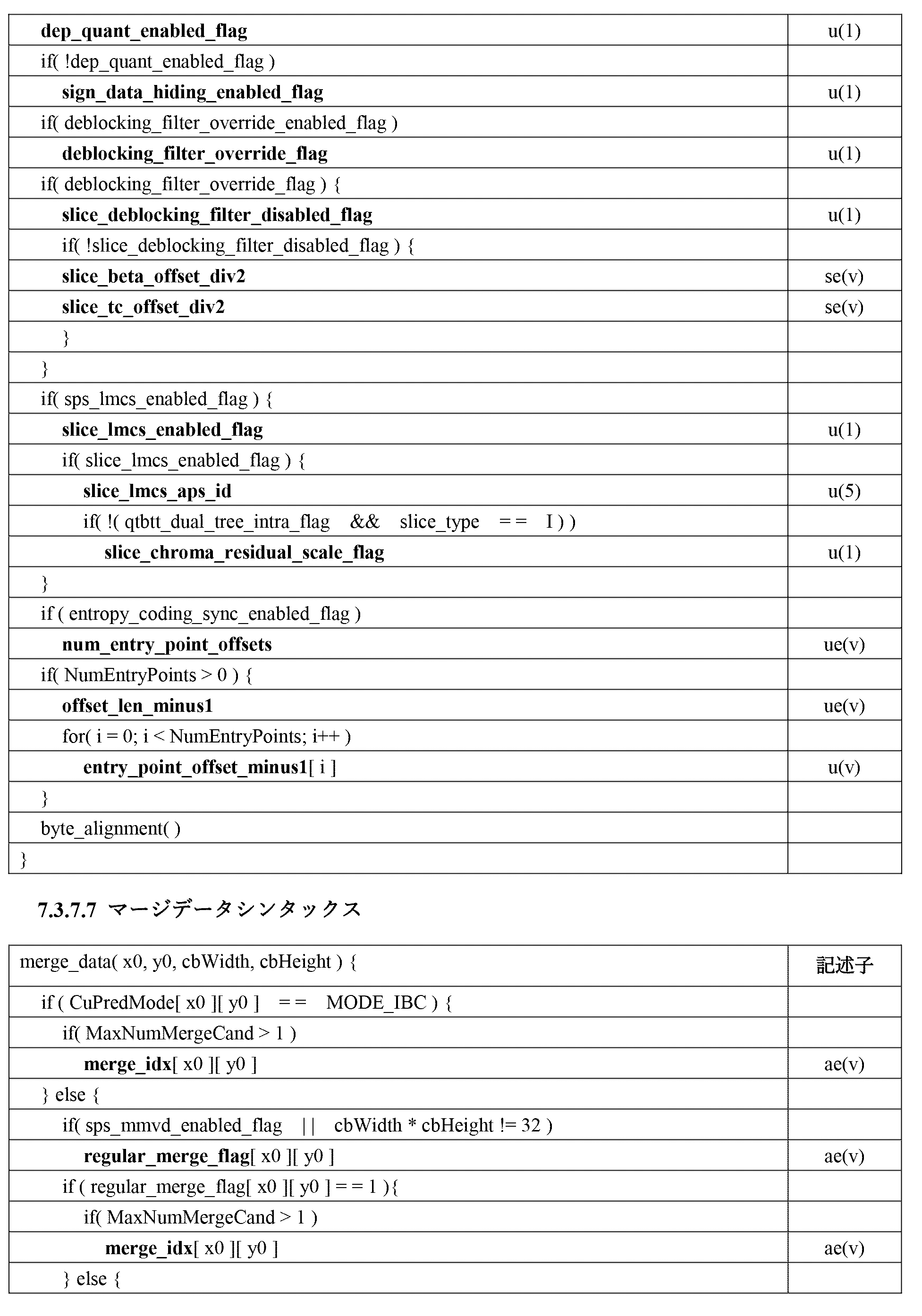
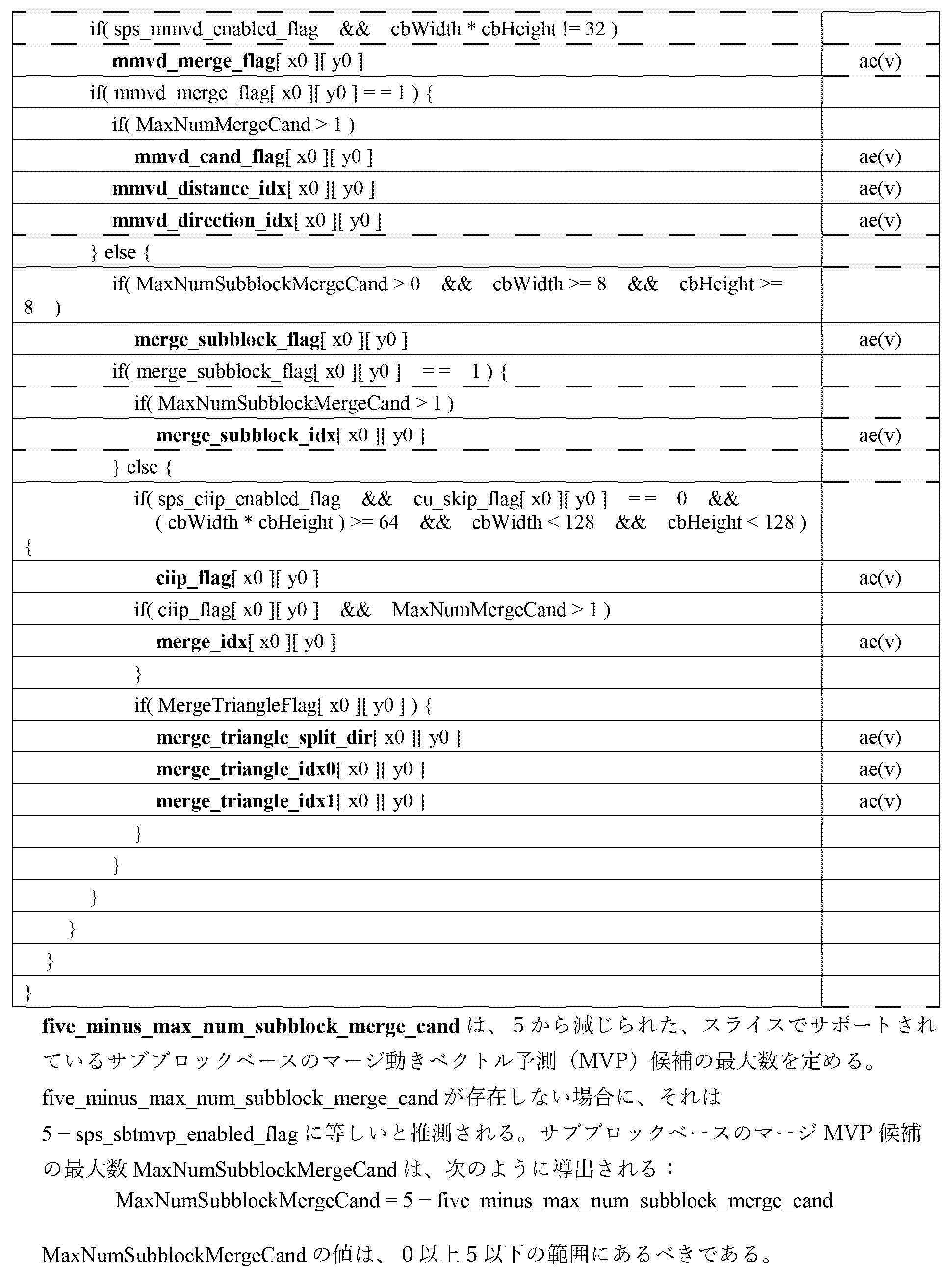
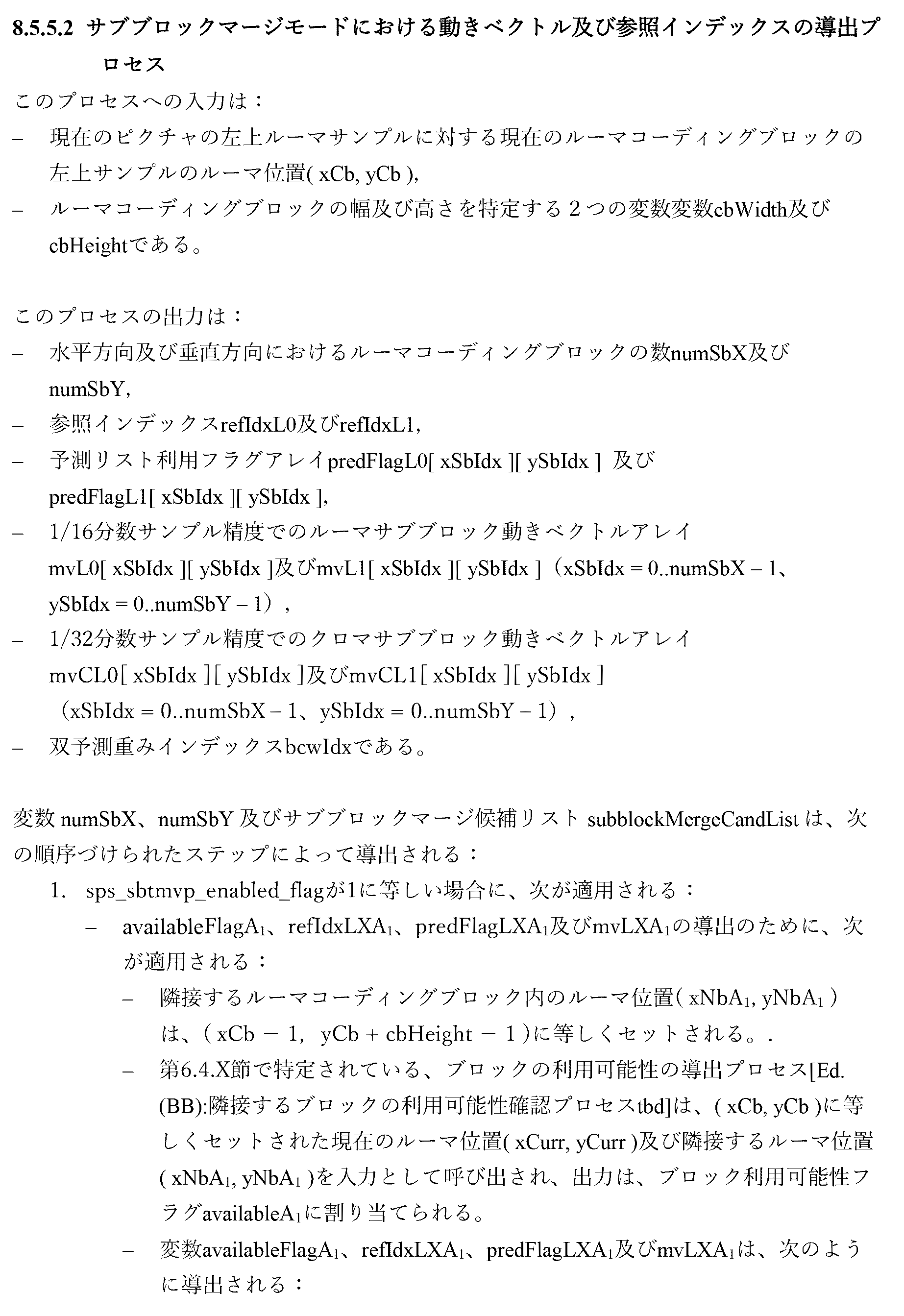
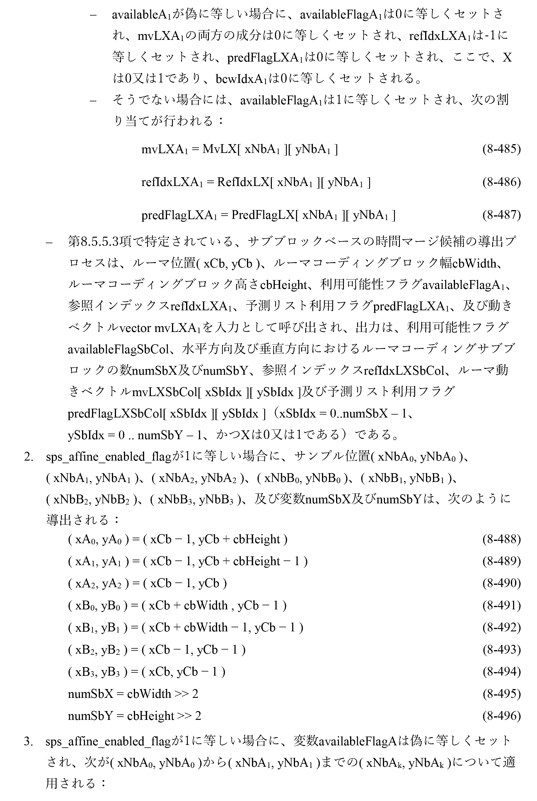

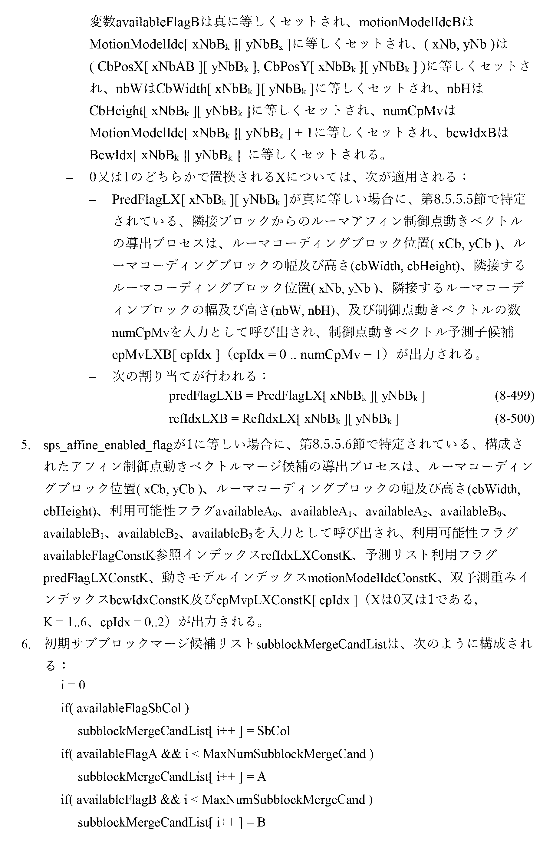
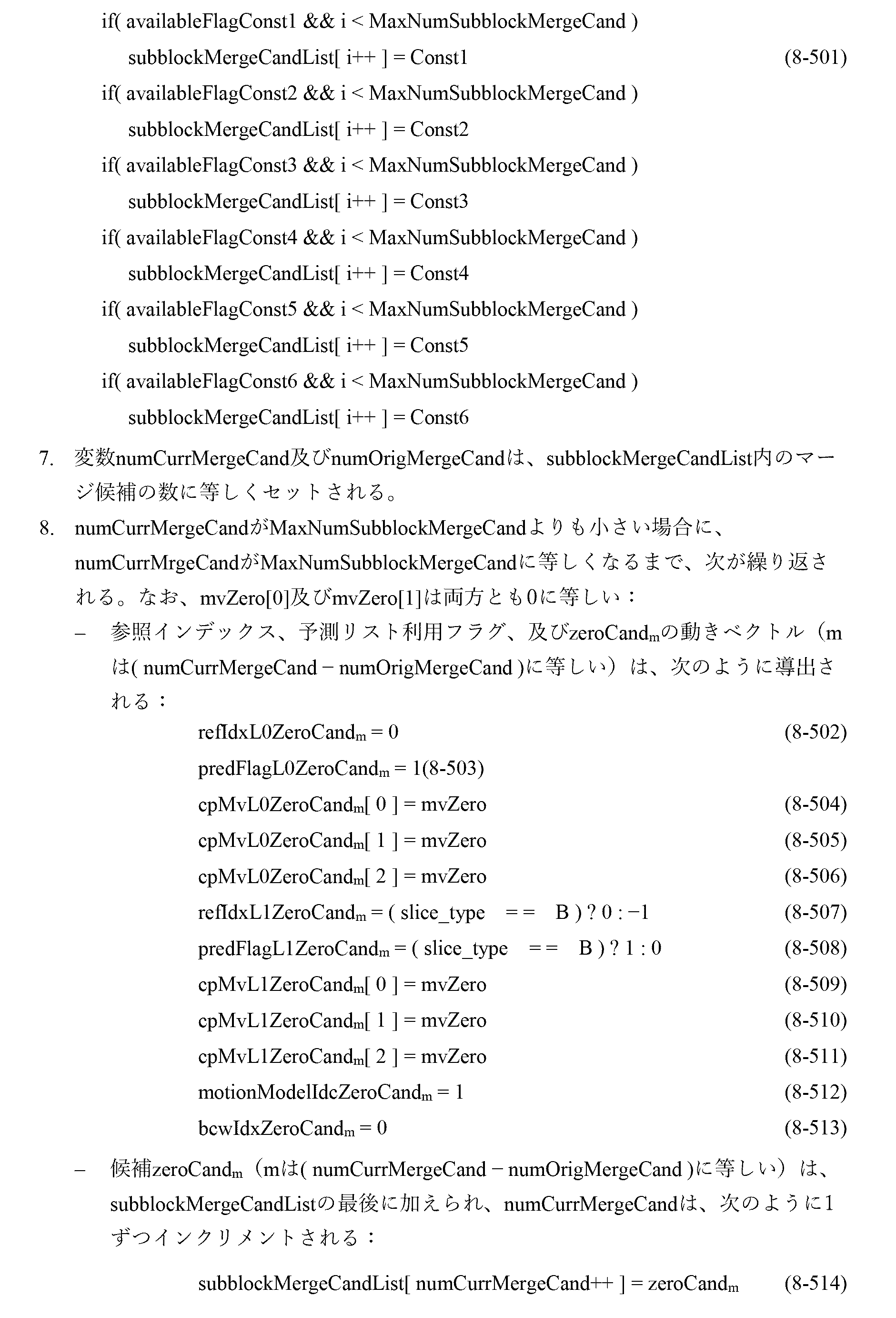
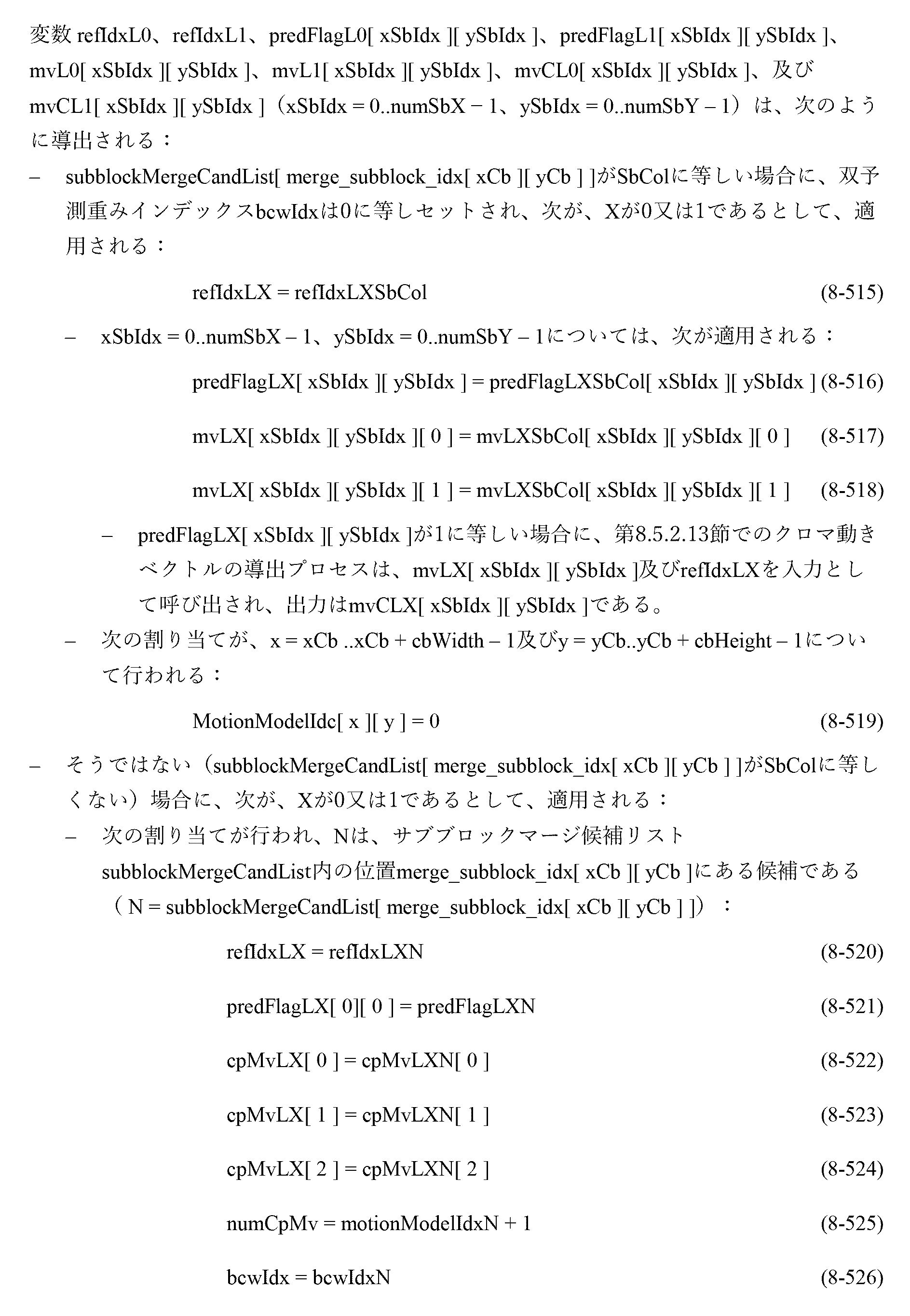
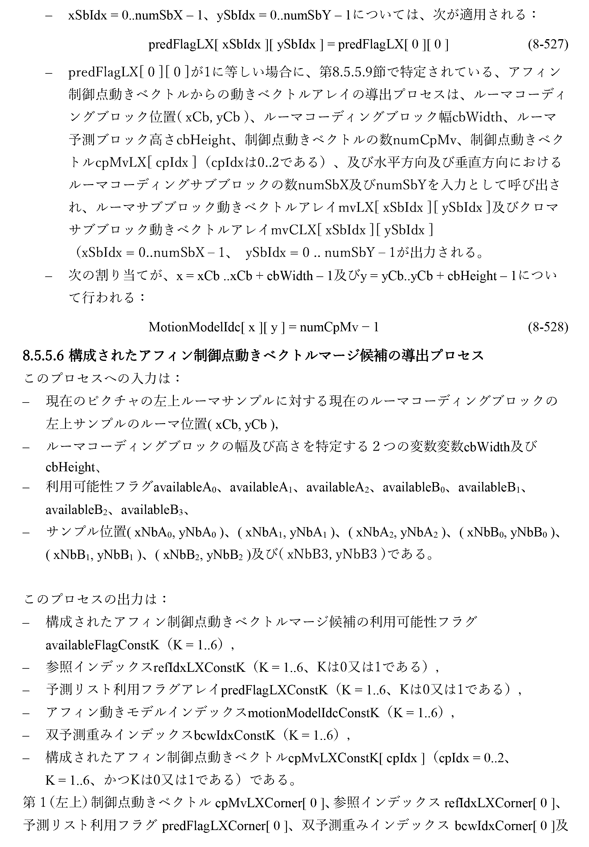

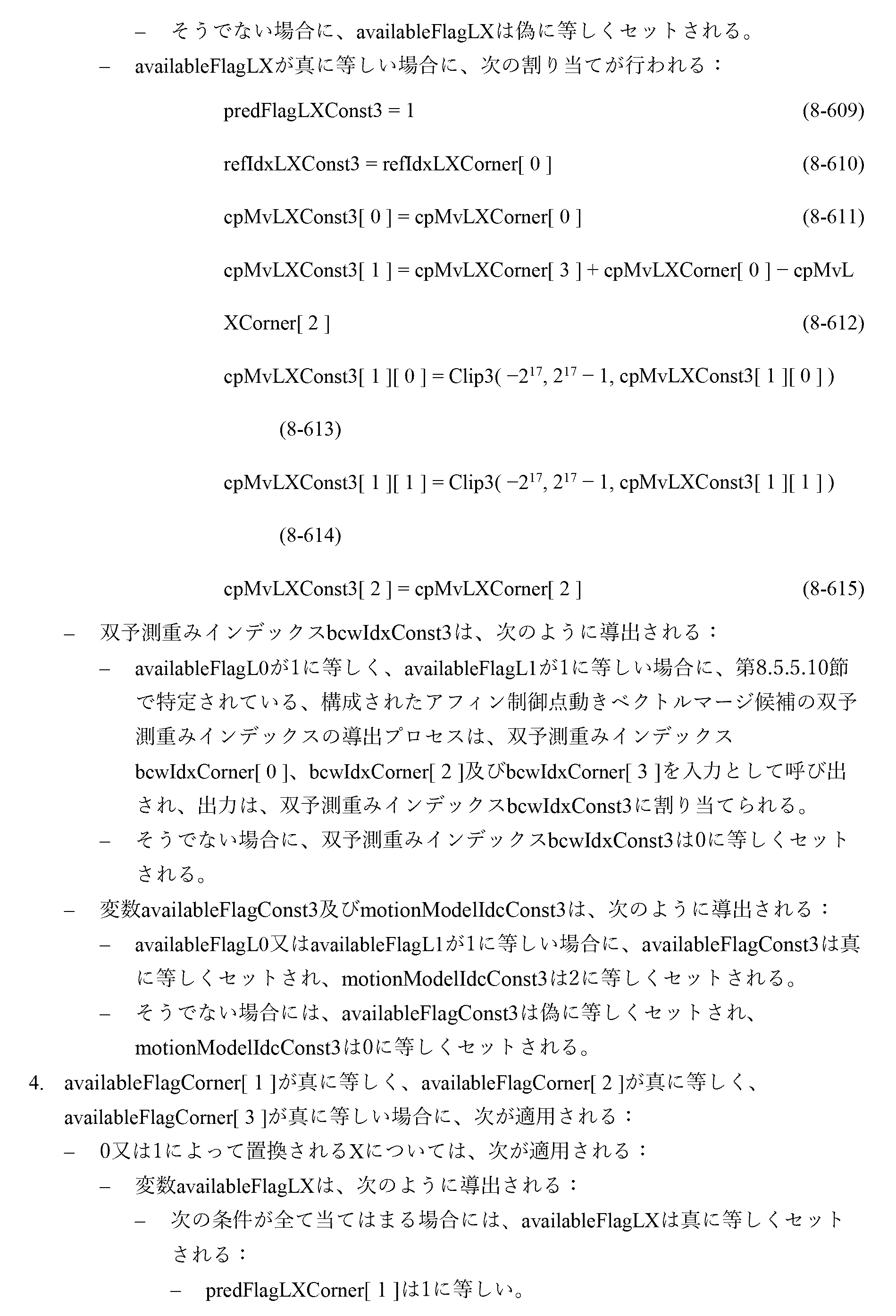
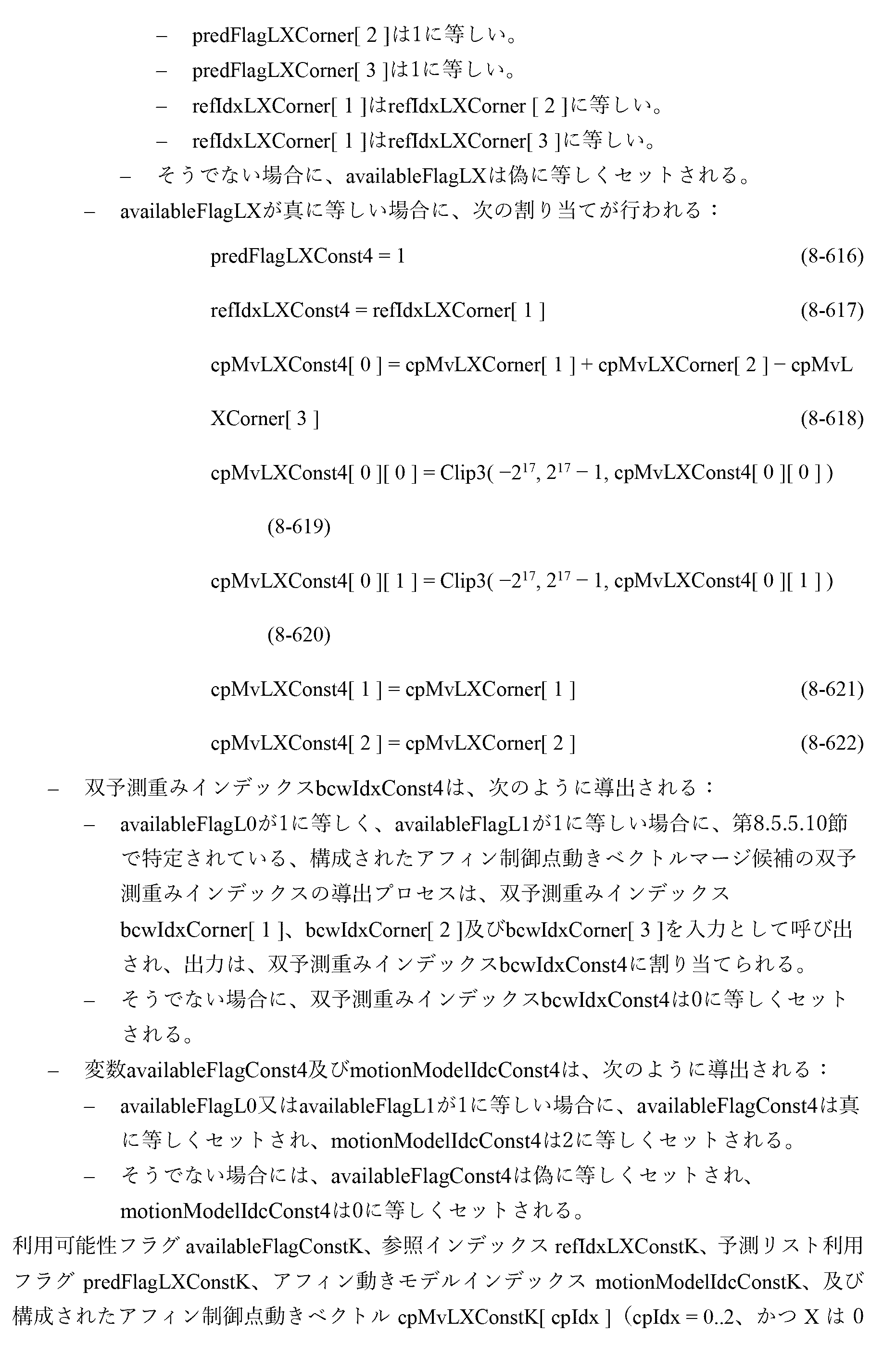

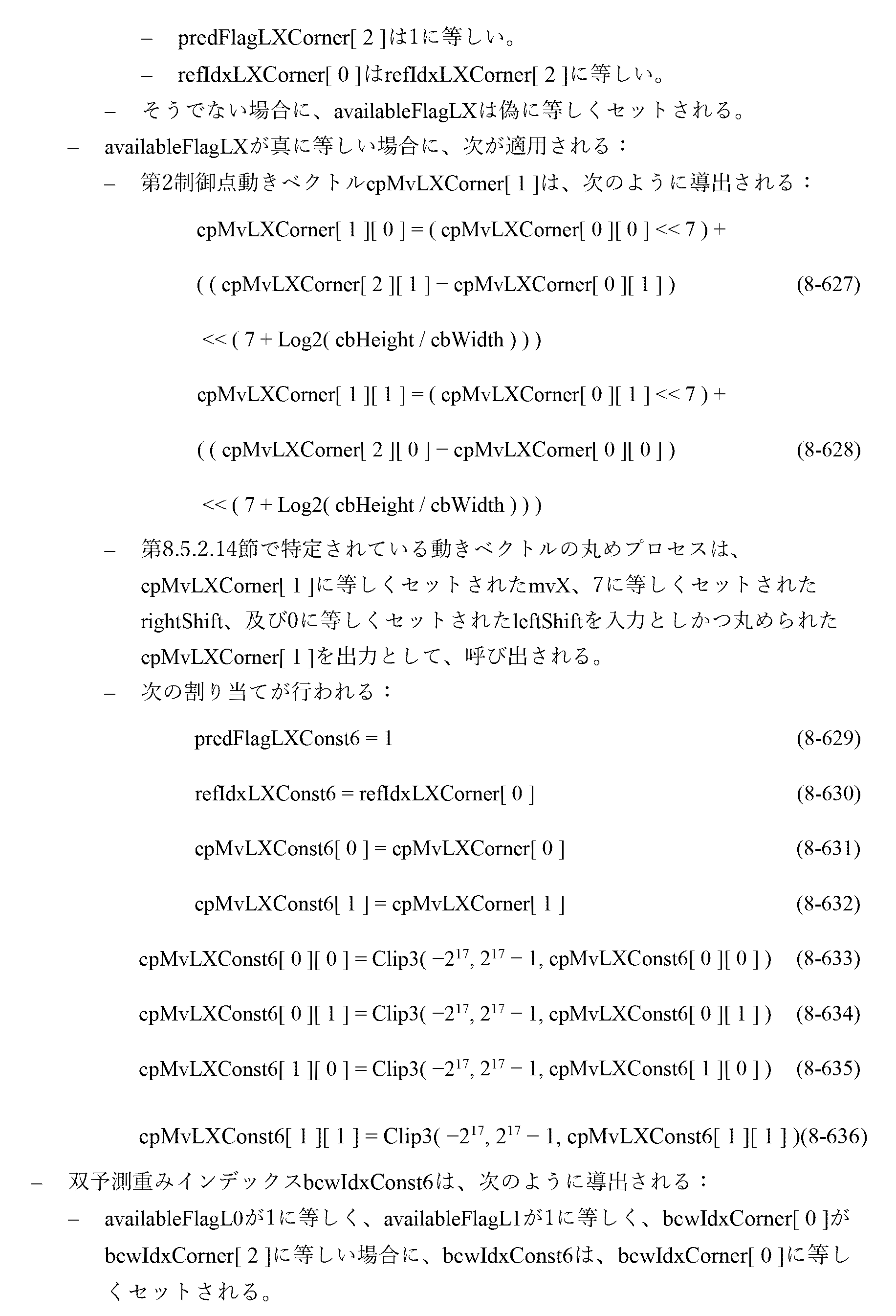

2.3.4.2.正則マージリスト
マージリスト設計とは異なり、VVCでは、履歴に基づいた動きベクトル予測(History-based Motion Vector Prediction)が用いられる。
2.3.4.2. Regular Merge List Unlike the merge list design, VVC uses History-based Motion Vector Prediction.
HMVPでは、前にコーディングされた動き情報が保存される、前にコーディングされたブロックの動き情報は、HMVP候補として定義される。複数のHMVP候補が、HMVPテーブルと名付けられたテーブルに保存され、このテーブルは、オン・ザ・フライで符号化/復号化プロセス中に保持される。HMVPテーブルは、新しいスライスの符号化/復号化を開始するときに空にされる。インターコーディングされたブロックが存在するときには、関連する動き情報が、新しいHMVP候補としてテーブルの最後のエントリに加えられる。全体のコーディングフローは図25に表される。 In HMVP, the motion information of a previously coded block in which the previously coded motion information is saved is defined as an HMVP candidate. Multiple HMVP candidates are stored in a table named HMVP table, which is maintained on-the-fly during the encoding/decoding process. The HMVP table is emptied when starting encoding/decoding a new slice. When an inter-coded block is present, the associated motion information is added to the last entry of the table as a new HMVP candidate. The entire coding flow is represented in FIG. 25.
HMVPは、AMVP及びマージ候補リスト構成プロセスの両方で使用され得る。図26は、変更されたマージ候補リスト構成プロセスを表す。TMVP候補挿入の後にマージ候補リストがいっぱいでないとき、HMVPテーブルに保存されているHMVP候補が、マージ候補リストに充てんするために利用される。1つのブロックが、通常は、動き情報に関して最も近い隣接ブロックとより高い相関を有していることを考えると、テーブル内のHMVP候補は、インデックスの降順で挿入される。テーブル内の最後のエントリが最初にリストに加えられ、一方、最初のエントリは最後に加えられる。同様に、冗長性除去がHMVP候補に対して適用される。利用可能なマージ候補の総数が、シグナリングされることを許されたマージ候補の最大数に達すると、マージ候補リスト構成プロセスは終了する。 HMVP may be used in both AMVP and merge candidate list construction processes. FIG. 26 depicts a modified merge candidate list construction process. When the merge candidate list is not full after TMVP candidate insertion, the HMVP candidates stored in the HMVP table are utilized to fill the merge candidate list. Given that one block typically has a higher correlation with its nearest neighboring block in terms of motion information, the HMVP candidates in the table are inserted in descending order of index. The last entry in the table is added to the list first, while the first entry is added last. Similarly, redundancy removal is applied to HMVP candidates. Once the total number of available merge candidates reaches the maximum number of merge candidates allowed to be signaled, the merge candidate list construction process ends.
図25は、アフィンマージモードのための候補位置を示す。 FIG. 25 shows candidate locations for affine merge mode.
図26は、変更されたマージリスト構成プロセスを示す。 FIG. 26 shows a modified merge list configuration process.
2.3.5.JVET-N0236
この寄稿は、オプティカルフローによりサブブロックベースアフィン動き補償された予測を精緻化する方法を提案している。サブブロックベースのアフィン動き補償が実行された後、予測サンプルは、オプティカルフロー式によって導出された差を加えることによって精緻化される。これは、オプティカルフローによる予測精緻化(PROF)と呼ばれる。提案されている方法は、メモリアクセスバンド幅を増大させずにピクセルレベル粒度でのインター予測を達成することができる。
2.3.5. JVET-N0236
This contribution proposes a method to refine sub-block-based affine motion compensated prediction with optical flow. After sub-block-based affine motion compensation is performed, the predicted samples are refined by adding the differences derived by the optical flow equation. This is called predictive refinement with optical flow (PROF). The proposed method can achieve inter-prediction at pixel-level granularity without increasing memory access bandwidth.
より細かい粒度の動き補償を達成するために、この寄稿は、オプティカルフローによりサブブロックベースのアフィン動き補償された予測を精緻化する方法を提案する。サブブロックベースのアフィン動き補償が実行された後に、ルーマ予測サンプルは、オプティカルフロー式によって導出された差を加えることによって精緻化される。この提案されているPROF(Prediction Refinement with Optical Flow)は、次の4つのステップとして記載される。 To achieve finer-grained motion compensation, this contribution proposes a method to refine sub-block-based affine motion-compensated prediction with optical flow. After subblock-based affine motion compensation is performed, the luma prediction samples are refined by adding the differences derived by the optical flow equation. This proposed PROF (Prediction Refinement with Optical Flow) is described as the following four steps.
ステップ1)サブブロックベースのアフィン動き補償が、サブブロック予測I(i,j)を生成するために実行される。 Step 1) Subblock-based affine motion compensation is performed to generate subblock predictions I(i,j).
ステップ2)サブブロック予測の空間勾配gx(i,j)及びgy(i,j)が、3タップフィルタ[-1,0,1]を用いて各サンプル位置で計算される。
gx(i,j)=I(i+1,j)-I(i-1,j)
gy(i,j)=I(i,j+1)-I(i,j-1)
Step 2) Spatial gradients g x (i,j) and g y (i,j) of the sub-block prediction are computed at each sample position using a 3-tap filter [-1,0,1].
g x (i, j) = I (i + 1, j) - I (i - 1, j)
g y (i, j) = I (i, j + 1) - I (i, j - 1)
サブブロック精度は、勾配計算のために各辺で1ピクセルずつ広げられる。メモリバンド幅及び複雑性を低減するよう、広げられた境界上のピクセルは、参照ピクチャ内の最も近い整数ピクセル位置からコピーされる。従って、領域パディングのための追加の補間は回避される。 The sub-block precision is widened by one pixel on each side for gradient calculations. To reduce memory bandwidth and complexity, pixels on the widened border are copied from the nearest integer pixel location in the reference picture. Therefore, additional interpolation for region padding is avoided.
ステップ3)ルーマ予測精緻化が、オプティカルフロー式によって計算される。
ΔI(i,j)=gx(i,j)×Δvx(i,j)+gy(i,j)×Δvy(i,j)
ここで、Δv(i,j)は、図27に示されるように、v(i,j)によって表される、サンプル位置(i,j)について計算されたピクセルMVと、ピクセル(i,j)が属するサブブロックのサブブロックMVとの間の差である。
Step 3) Luma prediction refinement is calculated by optical flow equation.
ΔI (i, j) = g x (i, j) x Δv x (i, j) + g y (i, j) x Δv y (i, j)
Here, Δv(i,j) is the pixel MV calculated for the sample position (i,j), represented by v(i,j), and the pixel (i,j ) is the difference between the subblock MV and the subblock MV to which the subblock belongs.
アフィンモデルパラメータ及びサブブロック中心に対するピクセル位置は、サブブロックごとに変化しないので、Δv(i,j)は、最初のサブブロックについて計算され、同じCU内の他のサブブロックに対して再利用され得る。x及びyを、ピクセル位置からサブブロックの中心までの水平及び垂直オフセットとすると、Δv(x,y)は、次の式によって導出され得る。

4パラメータアフィンモデルについては、

6パラメータアフィンモデルについては、

ステップ4)最後に、ルーマ予測精緻化がサブブロック予測I(i,j)に加えられる。最終的な予測I’は、次の式として生成される。
I’(i,j)=I(i,j)+ΔI(i,j)
Step 4) Finally, luma prediction refinement is added to the sub-block prediction I(i,j). The final prediction I' is generated as the following equation.
I'(i,j)=I(i,j)+ΔI(i,j)
2.3.6.ATMVPの改善に関するPCT/CN2018/124520及びPCT/CN2018/116889
これらの文献で、我々は、ATMVPモードの設計を妥当かつ効率的にするためのいくつかのアプローチを開示した。これらは両方とも、その全文を参照により援用される。
2.3.6. PCT/CN2018/124520 and PCT/CN2018/116889 regarding ATMVP improvements
In these documents, we disclosed several approaches to make the design of ATM VP mode reasonable and efficient. Both are incorporated by reference in their entirety.
3.実施形態によって解決された課題の例
VVCの現在の設計では、サブブロックベースの予測モードは次の問題を抱えている:
1)SPS内のアフィンAMVRフラグは、正則AMVRがオフされるときにオンされる可能性がある。
2)SPS内のアフィンAMVRフラグは、アフィンモードがオフされるときにオンされる可能性がある。
3)MaxNumSubblockMergeCandは、ATMVPが適用されないときに近似的にセットされない。
4)TMVPがスライスに対して無効にされ、ATMVPがシーケンスに対して有効にされるとき、Bスライスの同一位置ピクチャは識別されなかったが、同一位置ピクチャはATMVPプロセスで必要とされる。
5)TMVP及びATMVPは両方とも、参照ピクチャから動き情報をフェッチする必要があり、現在の設計では、それは同じであると想定されており、これは事前である可能性がある。
6)PROFは、そのオン/オフを制御するフラグを有するべきである。
3. Examples of Problems Solved by Embodiments In the current design of VVC, the subblock-based prediction mode suffers from the following problems:
1) The affine AMVR flag in SPS may be turned on when the canonical AMVR is turned off.
2) Affine AMVR flag in SPS may be turned on when affine mode is turned off.
3) MaxNumSubblockMergeCand is approximately not set when ATMVP is not applied.
4) When TMVP is disabled for a slice and ATMVP is enabled for a sequence, co-located pictures of B slices were not identified, but co-located pictures are required in the ATMVP process.
5) Both TMVP and ATMVP need to fetch motion information from a reference picture, and in the current design it is assumed to be the same, which could be a priori.
6) PROF should have a flag to control its on/off.
4.例となる実施形態
以下の詳細な発明は、一般概念を説明するための例と見なされるべきである。これらの発明は、狭い意味で解釈されるべきではない。更に、これらの発明は、如何なる方法でも組み合わせ可能である。いくつかの実施形態は、代替時間動きベクトル予測(ATMVP)技術の例を用いて記載されるが、代替の実施形態では、サブブロックベースの時間動きベクトル予測(sbTMVP)技術が適用可能であってもよい。
4. Exemplary Embodiments The following detailed invention should be considered as examples for illustrating general concepts. These inventions should not be construed in a narrow sense. Furthermore, these inventions can be combined in any way. Although some embodiments are described using examples of alternative temporal motion vector prediction (ATMVP) techniques, in alternative embodiments, sub-block-based temporal motion vector prediction (sbTMVP) techniques may be applied. Good too.
以下で記載されている方法は、他の種類の動き候補リスト(例えば、AMVP候補リスト)にも適用可能であり得る。 The method described below may also be applicable to other types of motion candidate lists (eg, AMVP candidate lists).
1.アフィンAMVRのための制御情報がシグナリングされるかどうかは、アフィン予測が適用されるか否かに依存し得る。
a)一例で、アフィンAMVRのための制御情報は、アフィン予測が適用されない場合にはシグナリングされない。
b)一例で、アフィンAMVRは、アフィン予測がコンフォーマンスビットストリーム(conformance bitstream)で適用されない場合には無効にされるべきある(例えば、アフィンAMVRの利用は、偽であるとシグナリングされるべきである)。
c)一例で、アフィンAMVRのためのシグナリングされた制御情報は、アフィン予測が適用されない場合には無視されて、適用されないと推測されてもよい。
1. Whether control information for affine AMVR is signaled may depend on whether affine prediction is applied.
a) In one example, control information for affine AMVR is not signaled if affine prediction is not applied.
b) In one example, affine AMVR should be disabled if affine predictions are not applied in the conformance bitstream (e.g., the use of affine AMVR should be signaled as false). be).
c) In one example, the signaled control information for affine AMVR may be ignored and inferred not to apply if affine prediction is not applied.
2.アフィンAMVRのための制御情報がシグナリングされるかどうかは、正則AMVRが適用されるか否かに依存し得る。
a)一例で、アフィンAMVRのための制御情報は、正則AMVRが適用されない場合にはシグナリングされない。
b)一例で、アフィンAMVRは、正則AMVRがコンフォーマンスビットストリームで適用されない場合には無効にされるべきである(アフィンAMVRフラグの利用は、偽であるとシグナリングされる)。
c)一例で、アフィンAMVRのためのシグナリングされた制御情報は、正則AMVRが適用されない場合には無視されて、適用されないと推測されてもよい。
d)一例で、適応動きベクトル分解の指示(例えば、1つのフラグ)は、正則AMVR(すなわち、並進運動に適用されるAMVR)及びアフィンAMVR(すなわち、アフィン運動に適用されるAMVR)などの複数のコーディング方法のためのAMVRの利用を制御するために、シーケンス/ピクチャ/スライス/タイルグループ/タイル/ブリック/他のビデオユニットでシグナリングされ得る。
i.一例で、そのような指示は、SPS/DPS/VPS/PPS/ピクチャヘッダ/スライスヘッダ/タイルグループヘッダでシグナリングされ得る。
ii.代替的に、更に、正則AMVR及び/又はアフィンAMVRの利用の指示をシグナリングすべきかどうかは、その指示に依存してもよい。
1)一例で、そのような指示が、適応動きベクトル分解が無効にされることを示すとき、正則AMVRの利用の指示のシグナリングはスキップされてもよい。
2)一例で、そのような指示が、適応動きベクトル分解が無効にされることを示すとき、アフィンAMVRの利用の指示のシグナリングはスキップされてもよい。
iii.代替的に、更に、アフィンAMVRの利用の指示をシグナリングすべきかどうかは、アフィン予測モードの利用及び指示に依存してもよい。
1)例えば、そのような指示は、アフィン予測モードが無効にされる場合にスキップされてもよい。
iv.一例で、そのような指示は、現在のスライス/タイルグループ/ピクチャが先行ピクチャからのみ予測可能である場合にはシグナリングされてなくてもよく、偽であると導出され得る。
v.一例で、そのような指示は、現在のスライス/タイルグループ/ピクチャが後続ピクチャからのみ予測可能である場合にはシグナリングされなくてもよく、偽であると導出され得る。
vi.一例で、そのような指示は、現在のスライス/タイルグループ/ピクチャが先行ピクチャ及び後続ピクチャの両方から予測可能であるときにシグナリングされ得る。
2. Whether control information for affine AMVR is signaled may depend on whether regular AMVR is applied.
a) In one example, control information for affine AMVR is not signaled if canonical AMVR is not applied.
b) In one example, affine AMVR should be disabled if canonical AMVR is not applied in the conformance bitstream (utilization of affine AMVR flag is signaled as false).
c) In one example, the signaled control information for affine AMVR may be ignored and inferred not to apply if canonical AMVR does not apply.
d) In one example, an indication of adaptive motion vector decomposition (e.g., one flag) may be used to specify multiple motion vector decompositions, such as canonical AMVR (i.e., AMVR applied to translational motion) and affine AMVR (i.e., AMVR applied to affine motion). may be signaled on sequences/pictures/slices/tile groups/tiles/bricks/other video units to control the utilization of AMVR for coding methods.
i. In one example, such an indication may be signaled in the SPS/DPS/VPS/PPS/picture header/slice header/tile group header.
ii. Alternatively, it may further depend on whether an indication of the use of canonical AMVR and/or affine AMVR is to be signaled.
1) In one example, signaling of an indication to utilize canonical AMVR may be skipped when such indication indicates that adaptive motion vector decomposition is disabled.
2) In one example, signaling of an indication to utilize affine AMVR may be skipped when such indication indicates that adaptive motion vector decomposition is disabled.
iii. Alternatively, further, whether to signal an indication of the use of affine AMVR may depend on the use and indication of the affine prediction mode.
1) For example, such instructions may be skipped if affine prediction mode is disabled.
iv. In one example, such an indication may not be signaled and may be derived to be false if the current slice/tile group/picture is only predictable from previous pictures.
v. In one example, such an indication may not be signaled and may be derived to be false if the current slice/tile group/picture is only predictable from subsequent pictures.
vi. In one example, such an indication may be signaled when the current slice/tile group/picture is predictable from both previous and subsequent pictures.
3.アフィンAMVRのための制御情報がシグナリングされるべきかどうかは、正則AMVRが適用されるか否かと、アフィン予測が適用されるか否かとに依存してもよい。
a)一例で、アフィンAMVRのための制御情報は、アフィン予測が適用されないか又は正則AMVRが適用されない場合にはシグナリングされない。
i.一例で、アフィンAMVRは、コンフォーマンスビットストリームでアフィン予測が適用されないか又は正則AMVRが適用されない場合には無効にされるべきである(例えば、アフィンAMVRの利用は、偽であるとシグナリングされるべきである)。
ii.一例で、アフィンAMVRのためのシグナリングされた制御情報は、アフィン予測が適用されないか又は正則AMVRが適用されない場合には無視され、適用されないと推測されてもよい。
b)一例で、アフィンAMVRのための制御情報は、アフィン予測が適用されずかつ正則AMVRが適用されない場合にはシグナリングされない。
i.一例で、アフィンAMVRは、コンフォーマンスビットストリームでアフィン予測が適用されずかつ正則AMVRが適用されない場合には無効にされるべきある(例えば、アフィンAMVRの利用は、偽であるとシグナリングされるべきである)。
ii.一例で、アフィンAMVRのためのシグナリングされた制御情報は、アフィン予測が適用されずかつ正則AMVRが適用されない場合には無視されて、適用されないと推測されてもよい。
3. Whether control information for affine AMVR should be signaled may depend on whether regular AMVR is applied and whether affine prediction is applied.
a) In one example, control information for affine AMVR is not signaled if affine prediction is not applied or regular AMVR is not applied.
i. In one example, affine AMVR should be disabled if affine prediction is not applied or canonical AMVR is not applied in the conformance bitstream (e.g., the use of affine AMVR is signaled as false). should).
ii. In one example, the signaled control information for affine AMVR may be ignored and inferred not to apply if affine prediction is not applied or regular AMVR is not applied.
b) In one example, control information for affine AMVR is not signaled if affine prediction is not applied and regular AMVR is not applied.
i. In one example, affine AMVR should be disabled if no affine predictions are applied in the conformance bitstream and no canonical AMVR is applied (e.g., the use of affine AMVR should be signaled as false). ).
ii. In one example, the signaled control information for affine AMVR may be ignored and presumed not to apply if affine prediction is not applied and regular AMVR is not applied.
4.サブブロックマージ候補リスト内の候補の最大数(MaxNumSubblockMergeCandと表される)は、ATMVPが有効にされるか否かに依存してもよい。ATMVPが有効にされるか否かは、SPS内のsps_sbtmvp_enabled_flagによってのみ示されなくてもよい。
a)例えば、ATMVPが有効にされるか否かは、シーケンスレベルでシグナリングされたフラグ(例えば、SPS内のsps_sbtmvp_enabled_flag)にしか依存しなくてもよい。それはまた、VPS、DPS、APS、PPS、スライスヘッダ、タイルグループヘッダ、ピクチャヘッダ、などのようなシーケンス/ピクチャ/スライス/タイルグループ/タイルレベルでの何らかの他のビデオユニットでシグナリングされた1つ又は複数のシンタックス要素にも依存してよい。
i.代替的に、ATMVPが有効にされるかどうかは、シグナリングによらずに暗黙的に導出されてもよい。
ii.例えば、ATMVPは、TMVPがピクチャ又はスライス又はタイルグループに対して有効にされない場合には、ピクチャ又はスライス又はタイルグループに対して有効にされない。
b)例えば、MaxNumSubblockMergeCandに関連したシンタックス要素(例えば、five_minus_max_num_subblock_merge_cand)をシグナリングすべきかどうか及び/又はどのようにシグナリングすべきかは、ATMVPが有効にされるか否かに依存してもよい。
i.例えば、five_minus_max_num_subblock_merge_candは、ATMVPが有効にされない場合にはコンフォーマンスビットストリームにおいて制約され得る。
1)例えば、five_minus_max_num_subblock_merge_candは、ATMVPが有効にされない場合には、固定数に等しいことを許されない。2つの例で、固定数は0又は5であってよい。
2)例えば、five_minus_max_num_subblock_merge_candは、ATMVPが有効にされない場合には、固定数よりも大きいことを許されない。1つの例で、固定数は4であってよい。
3)例えば、five_minus_max_num_subblock_merge_candは、ATMVPが有効にされない場合には、固定数よりも小さいことを許されない。1つの例で、固定数は1であってよい。
ii.例えば、five_minus_max_num_subblock_merge_candは、それが存在しない場合にはfive_minus_max_num_subblock_merge_cand-(ATMVPが有効にされる?0:1)としてセットされてもよく、ATMVPが有効にされるかどうかは、SPS内のフラグ(例えば、sps_sbtmvp_enabled_flag)にしか依存しないわけではない。
c)例えば、MaxNumSubblockMergeCandは、1つ以上のシンタックス要素(例えば、five_minus_max_num_subblock_merge_cand)及びATMVPが有効にされるか否かに応じて導出されてもよい。
i.例えば、MaxNumSubblockMergeCandは、MaxNumSubblockMergeCand=5-five_minus_max_num_subblock_merge_cand-(ATMVPが有効にされる?0:1)として導出され得る。
d)MaxNumSubblockMergeCandは、ATMVPが有効にされるときに1にセットされてもよく、アフィン運動予測は無効にされる。
4. The maximum number of candidates in the subblock merge candidate list (denoted as MaxNumSubblockMergeCand) may depend on whether ATMVP is enabled or not. Whether ATMVP is enabled or not may be indicated only by the sps_sbtmvp_enabled_flag in the SPS.
a) For example, whether ATMVP is enabled or not may only depend on flags signaled at sequence level (eg sps_sbtmvp_enabled_flag in SPS). It can also be one or more signaled in some other video unit at sequence/picture/slice/tile group/tile level like VPS, DPS, APS, PPS, slice header, tile group header, picture header, etc. It may also depend on multiple syntax elements.
i. Alternatively, whether ATMVP is enabled may be implicitly derived without signaling.
ii. For example, ATMVP is not enabled for a picture or slice or tile group if TMVP is not enabled for the picture or slice or tile group.
b) For example, whether and/or how the syntax elements related to MaxNumSubblockMergeCand (e.g., five_minus_max_num_subblock_merge_cand) should be signaled may depend on whether ATMVP is enabled or not.
i. For example, five_minus_max_num_subblock_merge_cand may be constrained in the conformance bitstream if ATMVP is not enabled.
1) For example, five_minus_max_num_subblock_merge_cand is not allowed to be equal to a fixed number if ATMVP is not enabled. In two examples, the fixed number may be 0 or 5.
2) For example, five_minus_max_num_subblock_merge_cand is not allowed to be greater than a fixed number if ATMVP is not enabled. In one example, the fixed number may be four.
3) For example, five_minus_max_num_subblock_merge_cand is not allowed to be less than a fixed number if ATMVP is not enabled. In one example, the fixed number may be one.
ii. For example, five_minus_max_num_subblock_merge_cand may be set as five_minus_max_num_subblock_merge_cand-(ATMVP enabled?0:1) if it does not exist, and whether ATMVP is enabled is determined by S Flags in PS (e.g. sps_sbtmvp_enabled_flag).
c) For example, MaxNumSubblockMergeCand may be derived depending on one or more syntax elements (eg, five_minus_max_num_subblock_merge_cand) and whether ATMVP is enabled or not.
i. For example, MaxNumSubblockMergeCand may be derived as MaxNumSubblockMergeCand=5-five_minus_max_num_subblock_merge_cand-(ATMVP enabled?0:1).
d) MaxNumSubblockMergeCand may be set to 1 when ATMVP is enabled and affine motion prediction is disabled.
5.デフォルト候補(並進及び/又はアフィン運動による)がサブブロックマージ候補リストに付け加えられてもよい。デフォルト候補は、サブブロックなどの予測タイプを有してもよく、あるいは、それは、ブロック全体予測によるものであってもよい。
a)一例で、デフォルト候補に対するブロック全体予測は、並進運動モデル(例えば、正則マージ候補に対するブロック全体予測)に続いてもよい。
b)一例で、デフォルト候補に対するサブブロック予測は、並進運動モデル(例えば、ATMP候補に対するサブブロック予測)に続いてもよい。
c)一例で、デフォルト候補に対するサブブロック予測は、アフィン運動モデル(例えば、アフィンマージ候補に対するサブブロック予測)に続いてもよい。
d)一例で、デフォルト候補は、0に等しいアフィンフラグを有してもよい。
i.代替的に、デフォルト候補は、1に等しいアフィンフラグを有してもよい。
e)一例で、ブロックに対する後続の手順は、そのブロックがデフォルト候補でコーディングされるかどうかに依存してもよい。
i.一例で、ブロックは、ブロック全体予測デコーディングされているものとして扱われ(例えば、選択されたデフォルト候補は、ブロック全体予測を使用する)、
1)例えば、PROFは、ブロックに適用されなくてもよい。
2)例えば、DMVR(Decode-side Motion Vector Refinement)は、ブロックに適用されてもよい。
3)例えば、BDOF(Bi-Directional Optical Flow)は、ブロックに適用されてもよい。
4)例えば、デブロッキングフィルタは、ブロック内のサブブロック間の境界に適用されなくてもよい。
ii.一例で、ブロックは、サブブロック予測でコーディングされているものとして扱われ(例えば、選択されたデフォルト候補は、サブブロック予測を使用する)、
1)例えば、PROFは、ブロックに適用されてもよい。
2)例えば、DMVR(Decode-side Motion Vector Refinement)は、ブロックに適用されなくてもよい。
3)例えば、BDOF(Bi-Directional Optical Flow)は、ブロックに適用されなくてもよい。
4)例えば、デブロッキングフィルタは、ブロック内のサブブロック間の境界に適用されてもよい。
iii.一例で、ブロックは並進予測でコーディングされているものとして扱われ、
1)例えば、PROFは、ブロックに適用されなくてもよい。
2)例えば、DMVR(Decode-side Motion Vector Refinement)は、ブロックに適用されてもよい。
3)例えば、BDOF(Bi-Directional Optical Flow)は、ブロックに適用されてもよい。
4)例えば、デブロッキングフィルタは、ブロック内のサブブロック間の境界に適用されなくてもよい。
iv.一例で、ブロックは、アフィン予測でコーディングされているものとして扱われ、
1)例えば、PROFは、ブロックに適用されてもよい。
2)例えば、DMVR(Decode-side Motion Vector Refinement)は、ブロックに適用されなくてもよい。
3)例えば、BDOF(Bi-Directional Optical Flow)は、ブロックに適用されなくてもよい。
4)例えば、デブロッキングフィルタは、ブロック内のサブブロック間の境界に適用されてもよい。
f)一例で、1つ又は複数の種類のデフォルト候補が、サブブロックマージ候補リストに置かれてもよい。
i.例えば、ブロック全体予測による第1の種類のデフォルト候補及びサブブロック予測による第2の種類のデフォルト候補の両方がサブブロックマージ候補リストに置かれてもよい。
ii.例えば、並進予測による第1の種類のデフォルト候補及びアフィン予測による第2の種類のデフォルト候補の両方がサブブロックマージ候補リストに置かれてもよい。
iii.各種類からのデフォルト候補の最大数は、ATMVPが有効にされるかどうか及び/又はアフィン予測が有効にされるかどうかに依存してもよい。
g)一例で、Bスライスについては、デフォルト候補は、全てのサブブロックについてゼロ動きベクトルを有してもよく、双予測が適用され、両方の参照ピクチャは0にセットされる。
h)一例で、Pスライスについては、デフォルト候補は、全てのサブブロックについてゼロ動きベクトルを有してもよく、片予測が適用され、参照ピクチャは0にセットされる。
i)どの種類のデフォルト候補がサブブロックマージ候補リストに置かれるかは、ATMVP及び/又はアフィン予測モードの利用に依存してもよい。
i.一例で、アフィン予測モードが有効にされるとき、アフィンフラグが1であるアフィン運動モデル(例えば、全てのCPMVが0に等しい)によるデフォルト候補が加えられ得る。
ii.一例で、アフィン予測モード及びATMVPの両方が有効にされるとき、アフィンフラグが0である並進運動モデル(例えば、ゼロMV)によるデフォルト候補及び/又はアフィンフラグが1であるアフィン運動モデル(例えば、全てのCPMVが0に等しい)によるデフォルト候補が加えられ得る。
1)一例で、並進運動モデルによるデフォルト候補は、アフィン運動モデルによるデフォルト候補の前に加えられ得る。
iii.一例で、アフィン予測が無効にされ、ATMVPが有効にされるとき、アフィンフラグが0である並進運動モデルによるデフォルト候補が加えられ得、アフィン運動によるデフォルト候補は加えられない。
j)上記の方法は、ATMVP候補及び/又は空間/時間/構成されたアフィンマージ候補をチェックした後でサブブロックマージ候補が満たされていないときに適用され得る。
5. Default candidates (by translation and/or affine motion) may be added to the subblock merging candidate list. The default candidate may have a prediction type such as subblock, or it may be by whole block prediction.
a) In one example, a whole block prediction for a default candidate may follow a translational motion model (eg, a whole block prediction for a canonical merge candidate).
b) In one example, sub-block prediction for the default candidate may follow a translational motion model (eg, sub-block prediction for the ATMP candidate).
c) In one example, sub-block prediction for default candidates may follow an affine motion model (eg, sub-block prediction for affine merge candidates).
d) In one example, the default candidate may have an affine flag equal to zero.
i. Alternatively, the default candidate may have an affine flag equal to one.
e) In one example, subsequent procedures for a block may depend on whether the block is coded with a default candidate.
i. In one example, the block is treated as being whole-block predictively decoded (e.g., the selected default candidate uses whole-block prediction);
1) For example, PROF may not be applied to blocks.
2) For example, DMVR (Decode-side Motion Vector Refinement) may be applied to blocks.
3) For example, BDOF (Bi-Directional Optical Flow) may be applied to blocks.
4) For example, deblocking filters may not be applied to boundaries between subblocks within a block.
ii. In one example, the block is treated as being coded with sub-block prediction (e.g., the selected default candidate uses sub-block prediction);
1) For example, PROF may be applied to blocks.
2) For example, DMVR (Decode-side Motion Vector Refinement) may not be applied to the block.
3) For example, BDOF (Bi-Directional Optical Flow) may not be applied to the block.
4) For example, a deblocking filter may be applied to boundaries between subblocks within a block.
iii. In one example, a block is treated as being coded with translational prediction,
1) For example, PROF may not be applied to blocks.
2) For example, DMVR (Decode-side Motion Vector Refinement) may be applied to blocks.
3) For example, BDOF (Bi-Directional Optical Flow) may be applied to blocks.
4) For example, deblocking filters may not be applied to boundaries between subblocks within a block.
iv. In one example, a block is treated as being coded with affine prediction,
1) For example, PROF may be applied to blocks.
2) For example, DMVR (Decode-side Motion Vector Refinement) may not be applied to the block.
3) For example, BDOF (Bi-Directional Optical Flow) may not be applied to the block.
4) For example, a deblocking filter may be applied to boundaries between subblocks within a block.
f) In one example, one or more types of default candidates may be placed in the sub-block merging candidate list.
i. For example, both a first type of default candidate based on whole block prediction and a second type of default candidate based on subblock prediction may be placed in the subblock merging candidate list.
ii. For example, both a first type of default candidate based on translational prediction and a second type of default candidate based on affine prediction may be placed in the subblock merging candidate list.
iii. The maximum number of default candidates from each type may depend on whether ATMVP is enabled and/or whether affine prediction is enabled.
g) In one example, for B slices, the default candidate may have zero motion vectors for all sub-blocks, bi-prediction is applied and both reference pictures are set to zero.
h) In one example, for P-slices, the default candidate may have zero motion vectors for all sub-blocks, uni-prediction is applied and the reference picture is set to zero.
i) What kind of default candidates are placed in the sub-block merging candidate list may depend on the use of ATMVP and/or affine prediction mode.
i. In one example, when affine prediction mode is enabled, a default candidate with an affine motion model with an affine flag of 1 (eg, all CPMVs equal to 0) may be added.
ii. In one example, when both affine prediction mode and ATMVP are enabled, the default candidate is a translational motion model with an affine flag of 0 (e.g., zero MV) and/or an affine motion model with an affine flag of 1 (e.g., A default candidate with all CPMVs equal to 0) may be added.
1) In one example, a default candidate based on a translational motion model may be added before a default candidate based on an affine motion model.
iii. In one example, when affine prediction is disabled and ATMVP is enabled, a default candidate with a translational motion model with an affine flag of 0 may be added, and a default candidate with affine motion is not added.
j) The above method may be applied when the sub-block merge candidates are not satisfied after checking the ATMVP candidates and/or the spatial/temporal/constructed affine merge candidates.
6.ATMVPがスライス又はタイルグループ又はピクチャに対して有効にされるかどうかなどのATMVPに関する情報は、スライスヘッダ又はタイルグループヘッダ又はスライスヘッダでシグナリングされてもよい。
a)一例で、ATMVPの同一位置ピクチャは、TMVPの同一位置ピクチャとは異なってもよい。
b)一例で、ATMVPに関する情報は、Iスライス又はIタイルグループ又はIピクチャについてシグナリングされなくてもよい。
c)一例で、ATMVPに関する情報は、ATMVPがシーケンスレベルで有効にされるとシグナリングされる(例えば、sps_sbtmvp_enabled_flagが1に等しい)場合にのみシグナリングされ得る。
d)一例で、ATMVPに関する情報は、TMVPがスライス又はタイルグループ又はピクチャに対して無効にされる場合には、そのスライス又はタイルグループ又はピクチャについてシグナリングされなくてもよい。
i.例えば、ATMVPは、この場合に、無効にされると推測され得る。
e)ATMVPは、ATMVPの利用のシグナリングされた情報にかかわらず、TMVPがスライス(又はタイルグループ又はピクチャ)に対して無効にされる場合には、そのスライス(又はタイルグループ又はピクチャ)に対して無効にされると推測され得る。
6. Information regarding ATMVP, such as whether ATMVP is enabled for a slice or tile group or picture, may be signaled in the slice header or tile group header or slice header.
a) In one example, an ATMVP co-located picture may be different from a TMVP co-located picture.
b) In one example, information regarding ATMVP may not be signaled for I-slices or I-tile groups or I-pictures.
c) In one example, information about ATMVP may only be signaled when ATMVP is enabled at the sequence level (eg, sps_sbtmvp_enabled_flag equals 1).
d) In one example, information regarding ATMVP may not be signaled for a slice or tile group or picture if TMVP is disabled for that slice or tile group or picture.
i. For example, ATMVP may be assumed to be disabled in this case.
e) ATMVP is disabled for a slice (or tile group or picture) if TMVP is disabled for that slice (or tile group or picture), regardless of the signaled information of ATMVP usage. It can be assumed that it is disabled.
7.サブブロックベースの時間マージ候補(例えば、時間アフィン動き候補)を加えるべきかどうかは、TMVPの利用に依存してもよい。
a)代替的に、それは、sps_temporal_mvp_enabled_flagの値に依存してもよい。
b)代替的に、それは、slice_temporal_mvp_enabled_flagの値に依存してもよい。
c)sps_temporal_mvp_enabled_flag又はslice_temporal_mvp_enabled_flagが真であるとき、サブブロックベースの時間マージ候補は、サブブロックマージ候補に加えられてもよい。
i.代替的に、sps_temporal_mvp_enabled_flag及びslice_temporal_mvp_enabled_flagが両方とも真であるとき、サブブロックベースの時間マージ候補は、サブブロックマージ候補に加えられてもよい。
ii.代替的に、sps_temporal_mvp_enabled_flag又はslice_temporal_mvp_enabled_flagが偽であるとき、サブブロックベースの時間マージ候補は、サブブロックマージ候補に加えられるべきではない。
d)代替的に、サブブロックベースの時間マージ候補を加えることの指示は、シーケンス/ピクチャ/スライス/タイルグループ/タイル/ブリック/他のビデオユニットでシグナリングされてもよい。
i.代替的に、更に、それは、時間動きベクトル予測の利用(例えば、sps_temporal_mvp_enabled_flag及び/又はslice_temporal_mvp_enabled_flag)に従って条件付きでシグナリングされてもよい。
7. Whether sub-block-based temporal merging candidates (eg, temporal affine motion candidates) should be added may depend on the usage of TMVP.
a) Alternatively, it may depend on the value of sps_temporal_mvp_enabled_flag.
b) Alternatively, it may depend on the value of slice_temporal_mvp_enabled_flag.
c) When sps_temporal_mvp_enabled_flag or slice_temporal_mvp_enabled_flag is true, sub-block-based temporal merging candidates may be added to the sub-block merging candidates.
i. Alternatively, when sps_temporal_mvp_enabled_flag and slice_temporal_mvp_enabled_flag are both true, subblock-based temporal merging candidates may be added to the subblock merging candidates.
ii. Alternatively, when sps_temporal_mvp_enabled_flag or slice_temporal_mvp_enabled_flag is false, sub-block-based temporal merging candidates should not be added to the sub-block merging candidates.
d) Alternatively, the indication to add sub-block based temporal merging candidates may be signaled in sequences/pictures/slices/tile groups/tiles/bricks/other video units.
i. Alternatively, it may also be signaled conditionally according to the utilization of temporal motion vector prediction (eg, sps_temporal_mvp_enabled_flag and/or slice_temporal_mvp_enabled_flag).
8.どの参照ピクチャリストから同一位置参照ピクチャが導出されるか(例えば、collocated_from_l0_flag)及び/又は同一位置参照ピクチャの参照インデックスなどの、同一位置参照ピクチャの指示は、時間動き情報にアクセスする必要がある複数のコーディング方法の利用に従って条件付きでシグナリングされてもよい。
a)一例で、条件は、ATMVP又はTMVPのうちの一方が有効にされることである。
b)一例で、条件は、ATMVP又はTMVP又はアフィン動き情報予測のうちの1つが有効にされることである。
8. An indication of the co-located reference picture, such as which reference picture list the co-located reference picture is derived from (e.g., collocated_from_l0_flag) and/or the reference index of the co-located reference picture, may be used to identify multiple users who need to access temporal motion information. may be signaled conditionally according to the use of a coding method.
a) In one example, the condition is that one of ATMVP or TMVP is enabled.
b) In one example, the condition is that one of ATMVP or TMVP or affine motion information prediction is enabled.
9.一例で、サブブロックベースの時間マージ候補は、ATMVP及びTMVPが両方とも現在のピクチャ/スライス/タイルグループに対して有効にされるときにのみサブブロックマージ候補リストに置かれてよい。
a)代替的に、サブブロックベースの時間マージ候補は、ATMVPが現在のピクチャ/スライス/タイルグループに対して有効にされるときにのみサブブロックマージ候補リストに置かれてよい。
9. In one example, subblock-based temporal merging candidates may be placed in the subblock merging candidate list only when ATMVP and TMVP are both enabled for the current picture/slice/tile group.
a) Alternatively, subblock-based temporal merging candidates may be placed in the subblock merging candidate list only when ATMVP is enabled for the current picture/slice/tile group.
10.MaxNumSubblockMergeCandは、サブブロックベースの時間マージ候補が使用され得るかどうかに依存してもよい。
a)代替的に、MaxNumSubblockMergeCandは、TMVPが使用され得るかどうかに依存してもよい。
b)例えば、MaxNumSubblockMergeCandは、サブブロックベースの時間マージ候補(又はTMVP)が使用され得ない場合には、4よりも大きくてはならない。
i.例えば、MaxNumSubblockMergeCandは、サブブロックベースの時間マージ候補(又はTMVP)が使用され得ず、ATMVPが使用され得る場合には、4よりも大きくてはならない。
ii.例えば、MaxNumSubblockMergeCandは、サブブロックベースの時間マージ候補(又はTMVP)が使用され得ず、ATMVPが使用され得ない場合には、4よりも大きくてはならない。
iii.例えば、MaxNumSubblockMergeCandは、サブブロックベースの時間マージ候補(又はTMVP)が使用され得ず、ATMVPが使用され得ない場合には、3よりも大きくてはならない。
10. MaxNumSubblockMergeCand may depend on whether subblock-based temporal merge candidates may be used.
a) Alternatively, MaxNumSubblockMergeCand may depend on whether TMVP may be used.
b) For example, MaxNumSubblockMergeCand must not be greater than 4 if subblock-based temporal merge candidates (or TMVP) cannot be used.
i. For example, MaxNumSubblockMergeCand must not be greater than 4 if subblock-based temporal merge candidates (or TMVP) cannot be used and ATMVP can be used.
ii. For example, MaxNumSubblockMergeCand should not be greater than 4 if subblock-based temporal merge candidates (or TMVP) cannot be used and ATMVP cannot be used.
iii. For example, MaxNumSubblockMergeCand should not be greater than 3 if subblock-based temporal merge candidates (or TMVP) cannot be used and ATMVP cannot be used.
11.PROFを行うべきかどうか及び/又はどのように行うべきかを示す1つ又は複数のシンタックス要素は、VPS、DPS、APS、PPS、スライスヘッダ、タイルグループヘッダ、ピクチャヘッダ、CTU、CU、PU、などのようなシーケンス/ピクチャ/スライス/タイルグループ/タイル/CTU行/CTU。CU/PU/TUレベルでの何らかのビデオユニットでシグナリングされ得る。
a)一例で、1つ又は複数のシンタックス要素(例えば、PROGが有効にされるかどうかを示すフラグ)は、アフィン予測が有効にされるかどうかを示すシンタックス要素などの他のシンタックス要素に応じて条件付きでシグナリングされ得る。
i.例えば、PROFが有効にされるかどうかを示すシンタックス要素は、シグナリングされなくてもよく、PROFは、アフィン予測が無効にされるときには、無効にされると推測される。
b)一例で、PROFが有効にされるかどうかを示すシンタックス要素は、アフィン予測がコンフォーマンスビットストリームで無効にされるときには、PROFが無効にされるとセットされなければならない。
c)一例で、アフィン予測がコンフォーマンスビットストリームで無効にされるときに、PROFが有効にされるかどうかを示すシグナリングされたシンタックス要素は、無視されて、PROFは、無効にされると推測される。
d)一例で、1つのシンタックス要素が、PROFが片予測にのみ適用されるか否かを示すためにシグナリングされてもよい。
11. One or more syntax elements that indicate whether and/or how PROF should be performed include: VPS, DPS, APS, PPS, slice header, tile group header, picture header, CTU, CU, PU , etc. sequences/pictures/slices/tile groups/tiles/CTU rows/CTUs. It may be signaled on any video unit at the CU/PU/TU level.
a) In one example, one or more syntax elements (e.g., a flag indicating whether PROG is enabled) may be combined with other syntax elements, such as a syntax element indicating whether affine prediction is enabled. Can be conditionally signaled depending on the element.
i. For example, a syntax element indicating whether PROF is enabled may not be signaled, and PROF is presumed to be disabled when affine prediction is disabled.
b) In one example, a syntax element indicating whether PROF is enabled must be set when PROF is disabled when affine prediction is disabled in a conformance bitstream.
c) In one example, when affine prediction is disabled in a conformance bitstream, a signaled syntax element indicating whether PROF is enabled is ignored and PROF is disabled. Guessed.
d) In one example, one syntax element may be signaled to indicate whether PROF applies only to one-sided predictions.
5.実施形態
次の全ての実施形態については、シンタックス要素は、SPS/PPS/スライスヘッダ/ピクチャヘッダ/タイルグループヘッダ/タイル又は他のビデオユニットなどの異なるレベルでシグナリングされてもよい。
5. Embodiments For all the following embodiments, syntax elements may be signaled at different levels such as SPS/PPS/slice header/picture header/tile group header/tile or other video units.
5.1,実施形態#1:SPS/PPS/スライスヘッダ/タイルグループヘッダでのsps_affine_amvr_enabled_flagに関するシンタックス設計の例
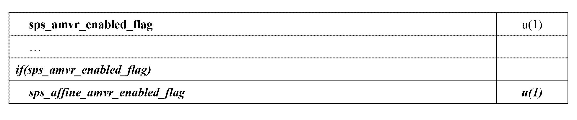
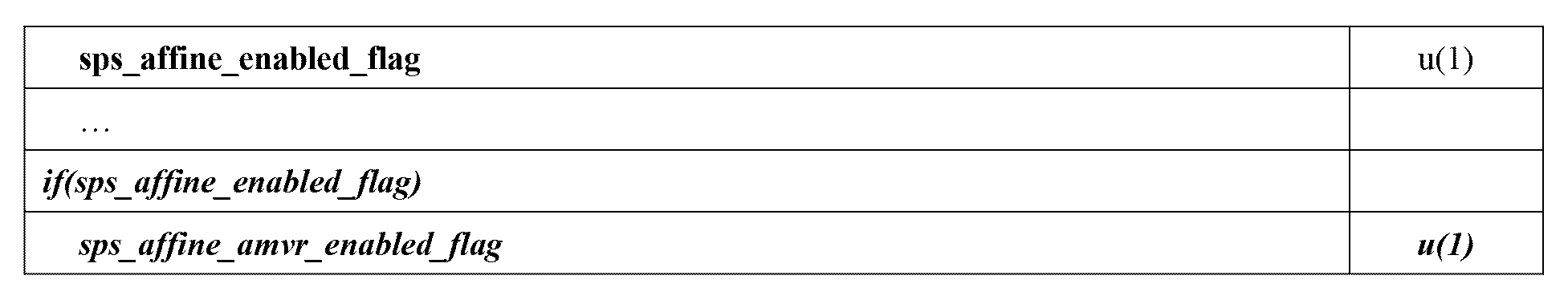
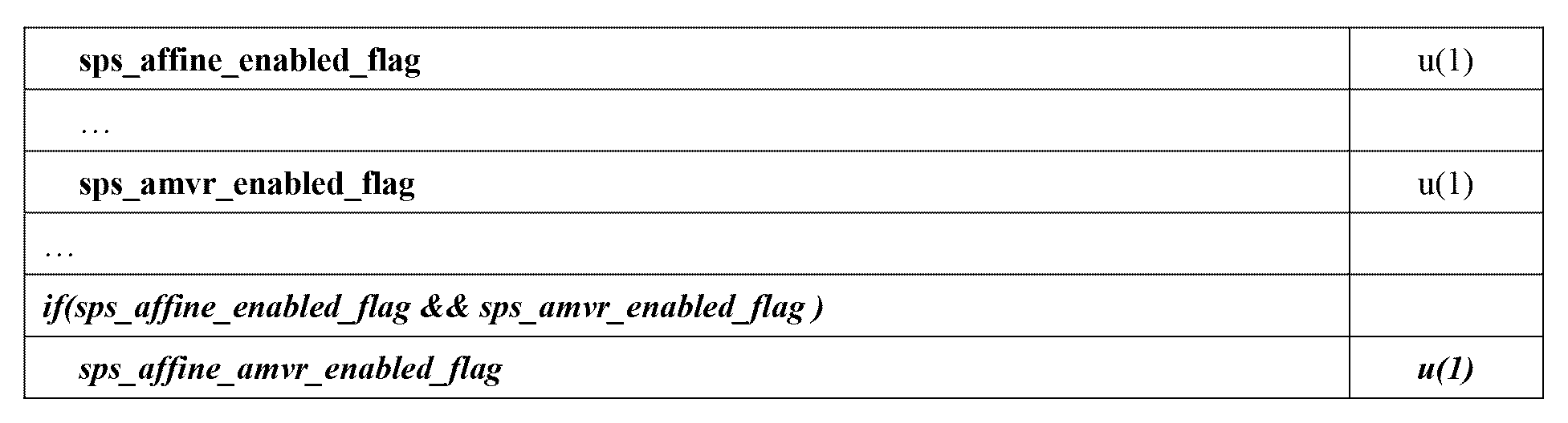

5.2.実施形態#2:five_minus_max_num_subblock_merge_candに関するセマンティクスの例
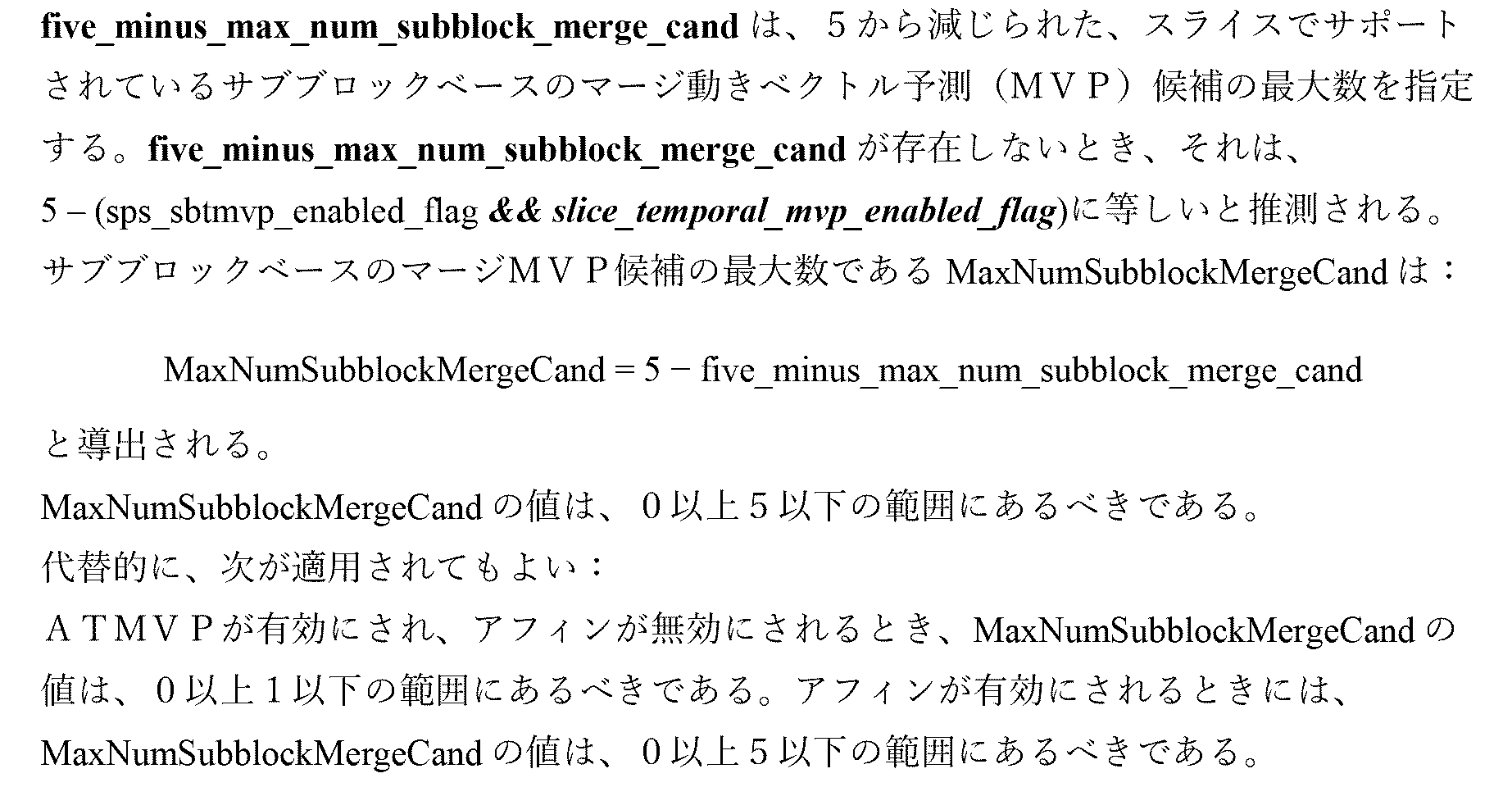
5.3.実施形態#3:スライスヘッダ(又はタイルグループヘッダ)でのATMVPのためのシンタックス要素の例
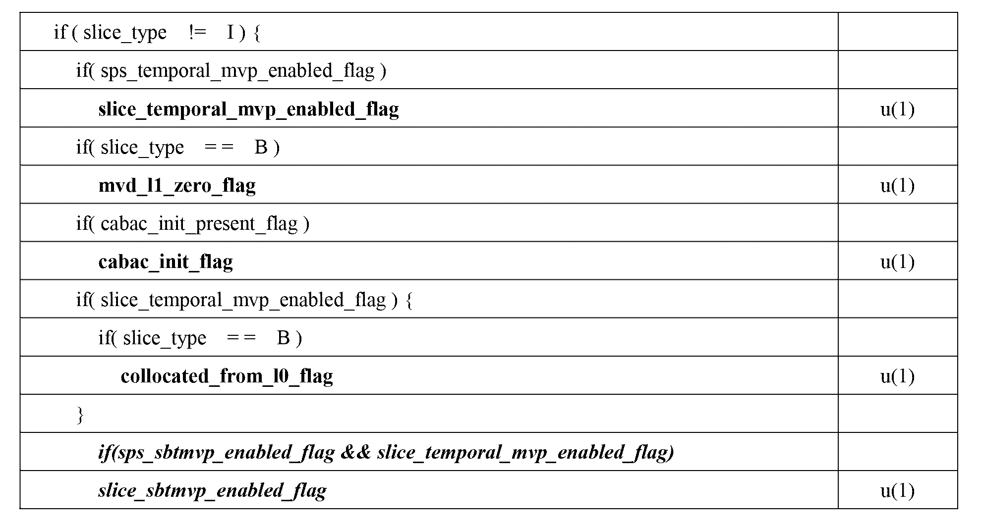
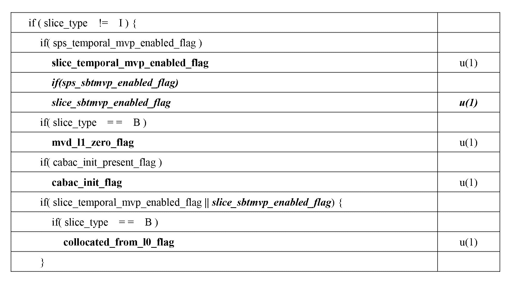
5.4.実施形態#4:スライスヘッダ(又はタイルグループヘッダ)でのサブブロックベースの時間マージ候補のためのシンタックス要素の例
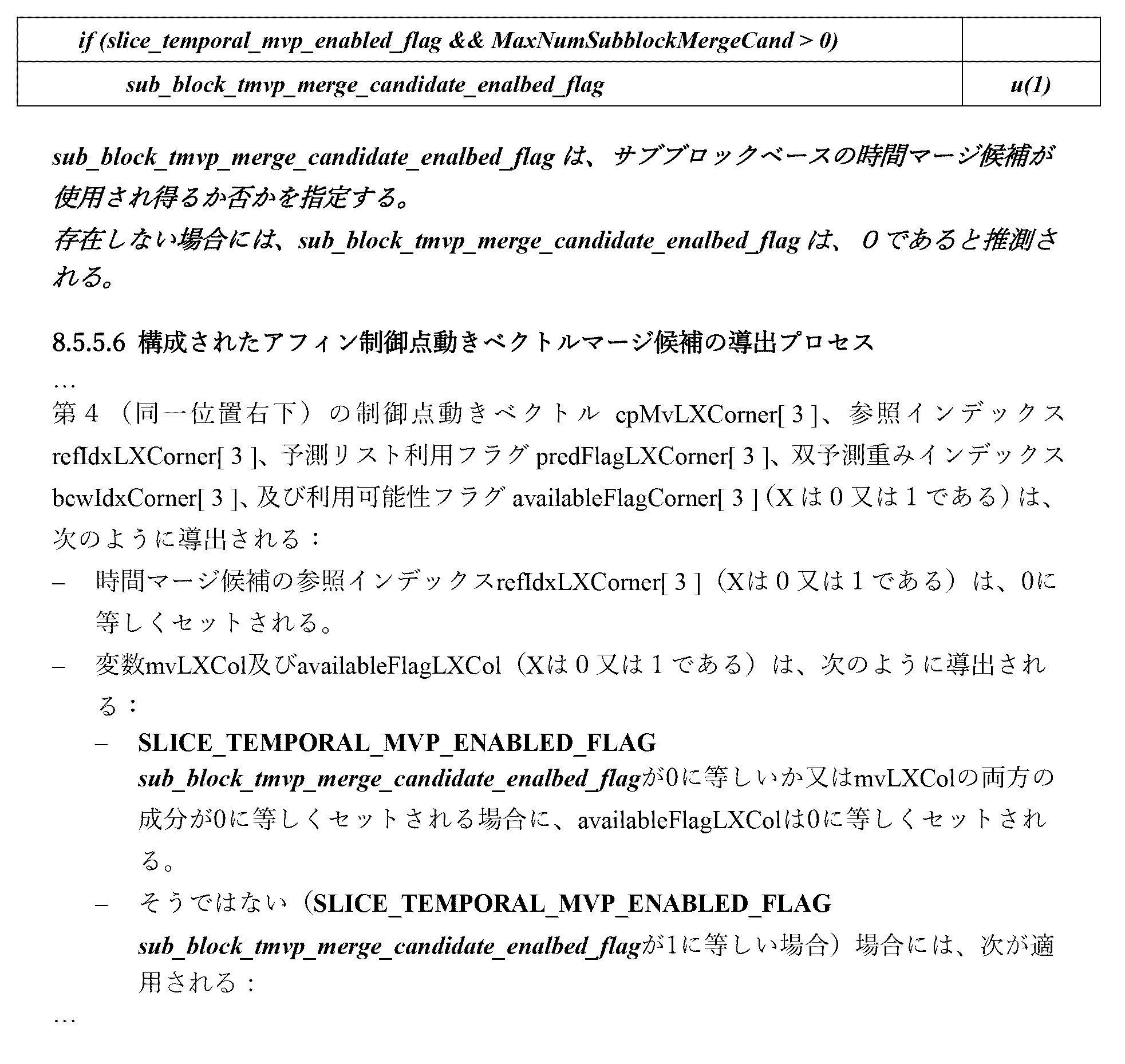
5.5.実施形態#5:SPSでPROFを制御するシンタックス/セマンティクスの例

図28は、ビデオ処理装置1400のブロック図である。装置1400は、本明細書で説明されている方法の1つ以上を実装するために使用されてよい。装置1400は、スマートフォン、タブレット、コンピュータ、インターネット・オブ・シングス(Internet of Things,IoT)レシーバ、などで具現されてよい。装置1400は、1つ以上のプロセッサ1402、1つ以上のメモリ1404、及びビデオ処理ハードウェア1406を含んでよい。プロセッサ1402は、本明細書で説明されている1つ以上の方法を実装するよう構成されてよい。メモリ(複数のメモリ)1404は、本明細書で説明されている方法及び技術を実装するために使用されるデータ及びコードを記憶するために使用されてよい。ビデオ処理ハードウェア1406は、ハードウェア回路で、本明細書で説明されているいくつかの技術を実装するために使用されてよい。
FIG. 28 is a block diagram of
図29は、ビデオ処理の例示的な方法2900のフローチャートである。方法2900は、ビデオの現在のビデオブロックとビデオのビットストリーム表現との間の変換を、アフィン適応動きベクトル分解技術を用いて実行するステップ(2902)を含み、それにより、ビットストリーム表現は、規則に基づいて、アフィン適応動きベクトル分解技術に関する制御情報を選択的に含む。
FIG. 29 is a flowchart of an
以下の例の列挙は、数ある課題の中でも、本明細書で記載されている技術的課題に対処することができる実施形態を提供する。 The following enumeration of examples provides embodiments that can address the technical problems described herein, among other problems.
1.ビデオ処理の方法であって、ビデオの現在のビデオブロックと前記ビデオのビットストリーム表現との間の変換を、アフィン適応動きベクトル分解技術を用いて実行するステップ(2902)を含み、それにより、前記ビットストリーム表現は、規則に基づいて、前記アフィン適応動きベクトル分解技術に関する制御情報を選択的に含む、方法。 1. A method of video processing, comprising performing (2902) a transformation between a current video block of a video and a bitstream representation of said video using an affine adaptive motion vector decomposition technique, whereby said A method wherein a bitstream representation selectively includes control information for the affine adaptive motion vector decomposition technique based on rules.
2.例1の方法であって、前記規則は、アフィン予測が前記変換中に使用される場合に前記制御情報を含め、アフィン予測が前記変換中に使用されない場合に前記制御情報を省略することを定める、方法。 2. The method of Example 1, wherein the rules provide for including the control information when affine prediction is used during the transformation and omitting the control information when affine prediction is not used during the transformation. ,Method.
3.例1の方法であって、前記規則は、アフィン予測が前記変換に適用されない場合に、前記変換中に適応動きベクトル分解ステップを使用することを除くことを更に定める、方法。 3. The method of Example 1, wherein the rules further provide for excluding the use of an adaptive motion vector decomposition step during the transform if affine prediction is not applied to the transform.
上記の例に関連した更なる例及び実施形態は、セクション4、項目1で提供される。
Further examples and embodiments related to the above examples are provided in
4.例1の方法であって、前記規則は、正則な適応動きベクトル分解ステップが前記変換中に使用されるか否かに基づき前記制御情報を包含又は省略することを定める、方法。 4. The method of Example 1, wherein the rules define including or omitting the control information based on whether a regular adaptive motion vector decomposition step is used during the transformation.
5.例4の方法であって、前記規則は、前記正則な適応動きベクトル分解ステップが前記変換中に適用されない場合に、前記制御情報が省略されることを定める、方法。 5. The method of Example 4, wherein the rule specifies that the control information is omitted if the regular adaptive motion vector decomposition step is not applied during the transformation.
6.例1の方法であって、前記制御情報は、前記変換中の複数の適応動きベクトル分解技術の仕様を示す同じフィールドを含む、方法。 6. The method of Example 1, wherein the control information includes the same field indicating specifications of multiple adaptive motion vector decomposition techniques during the transformation.
上記の例に関連した更なる例及び実施形態は、セクション4、項目2で提供される。
Further examples and embodiments related to the above example are provided in
7.例1の方法であって、前記規則は、正則な適応動きベクトル分解及びアフィン予測が前記変換中に使用されるか否かに基づき前記制御情報を包含又は省略することを定める、方法。 7. The method of Example 1, wherein the rules define including or omitting the control information based on whether regular adaptive motion vector decomposition and affine prediction are used during the transform.
8.例7の方法であって、前記規則は、前記正則な適応動きベクトル分解及びアフィン予測が両方とも前記変換中に適用されない場合に、前記制御情報を省略することを定める、方法。 8. The method of Example 7, wherein the rules provide for omitting the control information if the regular adaptive motion vector decomposition and affine prediction are both not applied during the transform.
上記の例に関連した更なる例及び実施形態は、セクション4、項目3で提供される。
Further examples and embodiments related to the above examples are provided in
9.ビデオ処理の方法であって、現在のビデオブロックとビットストリーム表現との間の変換中に、該変換のためのサブブロックマージ候補リストを決定するステップであり、前記サブブロックマージ候補リスト内の候補の最大数は、代替時間動きベクトル予測(ATMVP)が前記変換に適用されるか否かに依存する、前記決定するステップと、前記サブブロックマージ候補リストを用いて前記変換を実行するステップとを有する方法。 9. A method of video processing, the step of: determining a sub-block merging candidate list for the conversion during a conversion between a current video block and a bitstream representation, the candidates in the sub-block merging candidate list The maximum number of steps for determining and performing the transform using the sub-block merging candidate list depends on whether Alternative Temporal Motion Vector Prediction (ATMVP) is applied to the transform. How to have.
10.例9の方法であって、前記ビットストリーム表現内のフィールドは、代替時間動きベクトル予測が前記変換に適用されるか否かを示す、方法。 10. The method of Example 9, wherein a field in the bitstream representation indicates whether an alternative temporal motion vector prediction is applied to the transform.
11.例10の方法であって、前記フィールドは、シーケンスレベル又はビデオパラメータセットレベル又はピクチャパラメータセットレベル又はスライスレベル又はタイルグループレベル又はピクチャヘッダレベルにある、方法。 11. The method of Example 10, wherein the field is at a sequence level or a video parameter set level or a picture parameter set level or a slice level or a tile group level or a picture header level.
12.例9の方法であって、ATMVPが前記変換に適用され、アフィン予測が前記変換のために無効にされる場合に、前記候補の最大数は1にセットされる、方法。 12. The method of Example 9, wherein the maximum number of candidates is set to 1 when ATMVP is applied to the transform and affine prediction is disabled for the transform.
上記の例に関連した更なる例及び実施形態は、セクション4、項目4で提供される。
Further examples and embodiments related to the above examples are provided in
13.ビデオ処理の方法であって、現在のビデオブロックとビットストリーム表現との間の変換中に、該変換のためのサブブロックマージ候補リストに1つ以上のデフォルトのマージ候補を付け足すステップと、1つ以上のデフォルトのマージ候補が付け足された前記サブブロックマージ候補リストを用いて前記変換を実行するステップとを有する方法。 13. A method of video processing, the method comprising: during conversion between a current video block and a bitstream representation, appending one or more default merge candidates to a list of subblock merge candidates for the conversion; performing the conversion using the sub-block merging candidate list to which the default merging candidates have been added.
14.例13の方法であって、デフォルト候補は、サブブロック予測タイプと関連付けられる、方法。 14. The method of Example 13, wherein the default candidate is associated with a subblock prediction type.
15.例14の方法であって、前記サブブロック予測タイプは、並進運動モデル又はアフィン運動モデルに基づく予測を含む、方法。 15. The method of Example 14, wherein the sub-block prediction type includes prediction based on a translational motion model or an affine motion model.
16.例13の方法であって、デフォルト候補は、ブロック全体予測タイプと関連付けられる、方法。 16. The method of Example 13, wherein the default candidate is associated with a whole block prediction type.
17.例14の方法であって、前記ブロック全体予測タイプは、並進運動モデル又はアフィン運動モデルに基づく予測を含む、方法。 17. The method of Example 14, wherein the block-wide prediction type includes prediction based on a translational motion model or an affine motion model.
上記の例に関連した更なる例及び実施形態は、セクション4、項目5で提供される。
Further examples and embodiments related to the above examples are provided in
18.ビデオ処理の方法であって、ビデオの現在のビデオブロックとビットストリーム表現との間の変換中に、該変換への代替時間動きベクトル予測(ATMVP)の適用可能性を決定するステップであり、前記ビットストリーム表現内の1つ以上のビットは前記決定に対応する、前記決定するステップと、前記決定に基づき前記変換を実行するステップとを有する方法。 18. A method of video processing, comprising, during a conversion between a current video block of a video and a bitstream representation, determining the applicability of Alternative Temporal Motion Vector Prediction (ATMVP) to the conversion, the step of: A method comprising the steps of determining, wherein one or more bits in a bitstream representation correspond to the determination; and performing the transformation based on the determination.
19.例18の方法であって、前記1つ以上のビットは、ピクチャヘッダ又はスライスヘッダ又はタイルグループヘッダに含まれる、方法。 19. The method of Example 18, wherein the one or more bits are included in a picture header or a slice header or a tile group header.
20.例18~19の方法であって、前記変換は、時間動きベクトル予測(TMVP)を使用した前記ビデオの前記変換のために使用される他の同一位置ピクチャとは異なる同一位置ピクチャをATMVPのために使用する、方法。 20. The method of Examples 18-19, wherein the transformation uses a co-located picture for ATMVP that is different from other co-located pictures used for the transformation of the video using temporal motion vector prediction (TMVP). method used for.
上記の例に関連した更なる例及び実施形態は、セクション4、項目6で提供される。
Further examples and embodiments related to the above examples are provided in
21.ビデオ処理の方法であって、時間動きベクトル予測(TMVP)ステップ又は代替時間動きベクトル予測(ATMVP)に関連した条件に基づき選択的にサブブロックマージ候補リストを構成するステップと、該サブブロックマージ候補リストに基づき現在のビデオブロックと該現在のビデオブロックのビットストリーム表現との間の変換を実行するステップとを有する方法。 21. A method of video processing, comprising: selectively configuring a sub-block merging candidate list based on a condition related to a temporal motion vector prediction (TMVP) step or an alternative temporal motion vector prediction (ATMVP); performing a conversion between a current video block and a bitstream representation of the current video block based on a list.
22.例21の方法であって、前記条件は、シーケンスパラメータセットレベル又はスライスレベル又はタイルレベル又はブリックレベルでの前記ビットストリーム表現内のフラグの存在に対応する、方法。 22. The method of Example 21, wherein the condition corresponds to the presence of a flag in the bitstream representation at a sequence parameter set level or a slice level or a tile level or a brick level.
23.例21の方法であって、前記サブブロックマージ候補リストは、代替動きベクトル予測及びTMVPステップが両方とも、前記現在のビデオブロックが属するピクチャ又はタイル又はタイルグループについて有効にされる場合にのみ、サブブロックベースの時間マージ候補を用いて構成される、方法。 23. The method of Example 21, wherein the sub-block merging candidate list includes sub-block merging candidates only if alternative motion vector prediction and TMVP steps are both enabled for the picture or tile or tile group to which the current video block belongs. A method constructed using block-based temporal merging candidates.
24.例21の方法であって、前記サブブロックマージ候補リストは、ATMVP及びTMVPステップが両方とも、前記現在のビデオブロックが属するピクチャ又はタイル又はタイルグループについて有効にされる場合にのみ、サブブロックベースの時間マージ候補を用いて構成される、方法。 24. The method of Example 21, wherein the sub-block merging candidate list is configured for sub-block-based merging only if ATMVP and TMVP steps are both enabled for the picture or tile or tile group to which the current video block belongs. A method constructed using temporal merge candidates.
25.例21の方法であって、前記サブブロックマージ候補リストは、前記現在のビデオブロックが属するピクチャ又はタイル又はタイルグループについてATMVPが有効にされTMVPステップが無効にされる場合にのみ、サブブロックベースの時間マージ候補を用いて構成される、方法。 25. The method of Example 21, wherein the subblock merging candidate list is a subblock-based merging candidate list only when ATMVP is enabled and the TMVP step is disabled for the picture or tile or tile group to which the current video block belongs. A method constructed using temporal merge candidates.
上記の例に関連した更なる例及び実施形態は、セクション4、項目7及び9で提供される。
Further examples and embodiments related to the above examples are provided in
26.例21~25の方法であって、前記ビットストリーム表現内のフラグは、サブブロックベースの時間マージ候補が前記変換中に使用されるか否かに基づき包含又は省略される、方法。 26. The method of Examples 21-25, wherein a flag in the bitstream representation is included or omitted based on whether subblock-based temporal merging candidates are used during the transformation.
上記の例に関連した更なる例及び実施形態は、セクション4、項目10で提供される。
Further examples and embodiments related to the above examples are provided in
27.ビデオ処理の方法であって、ビデオの現在のビデオブロックと前記ビデオのビットストリーム表現との間の変換を、規則に基づいて、オプティカルフローを使用した予測精緻化(PROF)を選択的に用いて実行するステップを有し、前記規則は、(1)前記ビットストリーム表現内のフィールドの包含又は省略、あるいは、(2)アフィン予測が前記変換に適用されるか否か、を有する、方法。 27. A method of video processing, comprising: selectively applying predictive refinement using optical flow (PROF) based on rules to transform between a current video block of a video and a bitstream representation of the video; 12. A method comprising the steps of: (1) including or omitting fields in the bitstream representation; or (2) whether affine prediction is applied to the transform.
28.例27の方法であって、前記規則は、前記変換に対するアフィン予測の無効化によりPROFを無効にすることを定める、方法。 28. Example 27. The method of Example 27, wherein the rule provides for invalidating PROF by invalidating affine prediction for the transform.
29.例27の方法であって、アフィン予測が無効にされる場合に、PROFは前記変換に対して無効にされると推測される、方法。 29. The method of Example 27, wherein if affine prediction is disabled, PROF is inferred to be disabled for the transform.
30.例27の方法であって、前記規則は、前記ビットストリーム表現内の対応するフラグに基づき片予測のためにのみPROFを使用することを更に定める、方法。 30. Example 27. The method of Example 27, wherein the rule further defines to use PROF only for single prediction based on a corresponding flag in the bitstream representation.
上記の例に関連した更なる例及び実施形態は、セクション4、項目11で提供される。
Further examples and embodiments related to the above examples are provided in
31.例1乃至30のうちの1つ以上を実装するよう構成されたプロセッサを有するビデオ処理装置。 31. A video processing device having a processor configured to implement one or more of Examples 1-30.
32.プロセッサによって実行される場合に、該プロセッサに、例1乃至30のうちのいずれか1つ以上に記載の方法を実装させるコードを記憶しているコンピュータ可読媒体。 32. A computer-readable medium storing code that, when executed by a processor, causes the processor to implement the method described in any one or more of Examples 1-30.
本明細書における例の列挙において、変換との用語は、現在のビデオブロックのビットストリーム表現の生成又は現在のビデオブロックをビットストリーム表現から生成することを指し得る。ビットストリーム表現は、必ずしも、連続したビットのグループを表すわけではなく、コーディングされたピクセル値情報を表すコードワードで又はヘッダフィールドで含まれるビットに分けられてもよい。 In the enumeration of examples herein, the term transformation may refer to generating a bitstream representation of a current video block or generating a current video block from a bitstream representation. A bitstream representation does not necessarily represent a group of consecutive bits, but may be divided into bits included in a codeword or in a header field representing coded pixel value information.
上記の例では、規則は予め定義され、エンコーダ及びデコーダに知られていることがある。 In the above example, the rules may be predefined and known to the encoder and decoder.
図30は、本明細書で開示されている様々な技術が実装され得る、例となるビデオ処理システム3000を示すブロック図である。様々な実施は、システム3000のコンポーネントのいくつか又は全てを含んでよい。システム3000は、ビデオコンテンツを受け取る入力部3002を含んでよい。ビデオコンテンツは、生の又は圧縮されていないフォーマット、例えば、8又は10ビットマルチコンポーネントピクセル値で、受け取られてよく、あるいは、圧縮又はエンコードされたフォーマットであってもよい。入力部3002は、ネットワーク・インターフェース、ペリフェラル・バス・インターフェース、又はストレージ・インターフェースに相当してよい。ネットワーク・インターフェースの例には、Ethernet(登録商標)、受動光学ネットワーク(Passive Optical Network,PON)、などのような有線インターフェース、及びWi-Fi又はセルラーインターフェースのような無線インターフェースがある。
FIG. 30 is a block diagram illustrating an example
システム3000は、本明細書で説明されている様々なコーディング又は符号化方法を実装し得るコーディングコンポーネント3004を含んでよい。コーディングコンポーネント3004は、ビデオのコーディングされた表現を生成するよう入力部3002からコーディングコンポーネント3004の出力部までのビデオの平均ビットレートを低減してよい。コーディング技術は、従って、時々、ビデオ圧縮又はビデオトランスコーディング技術と呼ばれる。コーディングコンポーネント3004の出力は、コンポーネント3006によって表されているように、記憶されるか、あるいは、通信接続を介して伝送されるかのどちらかであってよい。入力部3002で受け取られたビデオの記憶又は通信されたビットストリーム(又はコーディングされた)表現は、表示インターフェース3010へ送られるピクセル値又は表示可能なビデオを生成するためにコンポーネント3008によって使用されてよい。ビットストリーム表現から、ユーザが見ることができるビデオを生成するプロセスは、時々、ビデオ圧縮解除と呼ばれる。更に、特定のビデオ処理動作は「コーディング」動作又はツールと呼ばれるが、コーディングツール又は動作はエンコーダで使用され、コーディングの結果を判定させる対応する復号化ツール又は動作は、デコーダで実行されることになる。
ペリフェラル・バス・インターフェース又は表示インターフェースの例には、ユニバーサル・シリアル・バス(Universal Serial Bus,USB)又は高精細マルチメディアインターフェース(High Definition Multimedia Interface,HDMI(登録商標))などが含まれ得る。ストレージ・インターフェースの例には、SATA(Serial Advanced Technology Attachment)、PCI、IDEインターフェース、などがある。本明細書で説明されている技術は、携帯電話機、ラップトップ、スマートフォン、あるいは、デジタルデータ処理及び/又はビデオ表示を実行することが可能な他のデバイスのような様々な電子機器で具現されてよい。 Examples of peripheral bus interfaces or display interfaces may include a Universal Serial Bus (USB) or a High Definition Multimedia Interface (HDMI®). Examples of storage interfaces include SATA (Serial Advanced Technology Attachment), PCI, and IDE interfaces. The techniques described herein may be embodied in a variety of electronic devices, such as mobile phones, laptops, smartphones, or other devices capable of performing digital data processing and/or video display. good.
図31は、視覚メディア処理の方法の例のフローチャートである。このフローチャートのステップは、本明細書のセクション4で例示的な実施形態1に関連して説明されている。ステップ3102で、プロセスは、視覚メディアデータのビットストリーム表現におけるアフィン適応動きベクトル分解(AMVR)技術に関する制御情報に応じて、前記視覚メディアデータに対して前記アフィンAMVR技術を使用すべきかどうかを決定し、前記制御情報は、規則に基づき前記ビットストリーム表現において包含又は削除される。ステップ3104で、プロセスは、前記視覚メディアデータと該視覚メディアデータの前記ビットストリーム表現との間の変換を実行する。
FIG. 31 is a flowchart of an example method of visual media processing. The steps of this flowchart are described in connection with
図32は、視覚メディア処理の方法の例のフローチャートである。このフローチャートのステップは、本明細書のセクション4で例示的な実施形態4に関連して説明されている。ステップ3202で、プロセスは、サブブロックベースの時間的動きベクトル予測(sbTMVP)技術が視覚メディアデータに適用されるか否かの決定を行う。ステップ3204で、前記決定に応答して、プロセスは、前記視覚メディアデータに含まれる現在のビデオブロックについてサブブロックマージ候補リストを生成する。ステップ3206で、プロセスは、前記サブブロックマージ候補リストを用いて、前記現在のビデオブロックと該現在のビデオブロックのビットストリーム表現との間の変換を実行する。
FIG. 32 is a flowchart of an example method of visual media processing. The steps of this flowchart are described in connection with
図33は、視覚メディア処理の方法の例のフローチャートである。このフローチャートのステップは、本明細書のセクション4で例示的な実施形態5に関連して説明されている。ステップ3302で、プロセスは、現在のビデオブロックとビットストリーム表現との間の変換中に、該変換のためのサブブロックマージ候補リストに1つ以上のデフォルトのマージ候補を付け足す。ステップ3304で、プロセスは、1つ以上のデフォルトのマージ候補を付け足された前記サブブロックマージ候補リストを用いて、前記変換を実行する。
FIG. 33 is a flowchart of an example method of visual media processing. The steps of this flowchart are described in connection with exemplary embodiment 5 in
図34は、視覚メディア処理の方法の例のフローチャートである。このフローチャートのステップは、本明細書のセクション4で例示的な実施形態6に関連して説明されている。ステップ3402で、プロセスは、ビデオの現在のビデオブロックとビットストリーム表現との間の変換中に、該変換へのサブブロックベースの時間的動きベクトル予測(sbTMVP)の適用可能性を決定する。ここで、ビットストリーム表現中の1つ以上のビットは、前記決定に対応する。ステップ3404で、プロセスは、前記決定に基づき前記変換を実行する。
FIG. 34 is a flowchart of an example method of visual media processing. The steps of this flowchart are described in connection with exemplary embodiment 6 in
図35は、視覚メディア処理の方法の例のフローチャートである。このフローチャートのステップは、本明細書のセクション4で例示的な実施形態7に関連して説明されている。ステップ3502で、プロセスは、時間的動きベクトル予測(TMVP)ステップ又はサブブロックベースの時間的動きベクトル予測(sbTMVP)ステップに関連した条件に基づき選択的にサブブロックマージ候補リストを構成する。ステップ3504で。プロセスは、前記サブブロックマージ候補リストに基づき現在のビデオブロックと該現在のビデオブロックのビットストリーム表現との間の変換を実行する。
FIG. 35 is a flowchart of an example method of visual media processing. The steps of this flowchart are described in connection with exemplary embodiment 7 in
図36は、視覚メディア処理の方法の例のフローチャートである。このフローチャートのステップは、本明細書のセクション4で例示的な実施形態8に関連して説明されている。ステップ3602で、プロセスは、視覚メディアデータと該視覚メディアデータのビットストリーム表現との間の変換中に、前記視覚メディアデータに関連した同一位置(collocated)参照ピクチャに関する情報を決定する。ここで、情報は、時間動き情報にアクセスするコーディングモードが有効にされるかどうかに基づき前記ビットストリーム表現において包含又は削除される。ステップ3604で、プロセスは、前記情報に従って前記同一位置参照ピクチャを決定する。ステップ3606で、プロセスは、前記同一位置参照ピクチャに基づき、前記視覚メディアデータと該視覚メディアデータの前記ビットストリーム表現との間の前記変換を実行する。
FIG. 36 is a flowchart of an example method of visual media processing. The steps of this flowchart are described in connection with exemplary embodiment 8 in
図37は、視覚メディア処理の方法の例のフローチャートである。このフローチャートのステップは、本明細書のセクション4で例示的な実施形態11に関連して説明されている。ステップ3702で、プロセスは、視覚メディアデータのビデオブロックと前記視覚メディアデータのビットストリーム表現との間の変換を実行する。ステップ3704で、プロセスは、前記変換中に、規則に基づき前記ビットストリーム表現において包含又は削除される制御情報に応じて、オプティカルフローを使用した予測精緻化(PROF)を適用すべきかどうか決定する。
FIG. 37 is a flowchart of an example method of visual media processing. The steps of this flowchart are described in connection with exemplary embodiment 11 in
これより、本明細書のいくつかの実施形態が、箇条書き形式で与えられている。 Some embodiments of this specification are now presented in bulleted form.
A1.視覚メディア処理の方法であって、
視覚メディアデータのビットストリーム表現におけるアフィン適応動きベクトル分解(AMVR)技術に関する制御情報に応じて、前記視覚メディアデータに対して前記アフィンAMVR技術を使用すべきかどうかを決定するステップであり、前記制御情報は、規則に基づき前記ビットストリーム表現において包含又は削除される、前記決定するステップと、
前記視覚メディアデータと該視覚メディアデータの前記ビットストリーム表現との間の変換を実行するステップと
を有する方法。
A1. A method of visual media processing, the method comprising:
determining whether to use the affine adaptive motion vector decomposition (AMVR) technique for the visual media data in response to control information regarding an affine adaptive motion vector decomposition (AMVR) technique in a bitstream representation of the visual media data; are included or removed in the bitstream representation based on rules;
performing a conversion between the visual media data and the bitstream representation of the visual media data.
A2.箇条A1に記載の方法であって、
前記規則は、
(1)アフィン予測が前記変換中に使用されるかどうか、
(2)正則AMVR技術が前記変換中に使用されるかどうか、
(3)適応動きベクトル分解に関する情報により、前記アフィンAMVR技術が有効又は無効にされることが示されるかどうか
のうちの少なくとも1つに基づき、前記制御情報が前記ビットストリーム表現において包含又は削除されることを定める、
方法。
A2. The method described in Clause A1,
The said rule is
(1) whether affine prediction is used during said transformation;
(2) whether canonical AMVR techniques are used during said conversion;
(3) the control information is included or removed in the bitstream representation based on at least one of whether information regarding adaptive motion vector decomposition indicates that the affine AMVR technique is enabled or disabled; stipulate that
Method.
A3.箇条A1に記載の方法であって、
前記規則は、アフィン予測が前記変換中に使用されない場合に前記制御情報を除くことを定める、
方法。
A3. The method described in Clause A1,
the rules provide for removing the control information if affine prediction is not used during the transformation;
Method.
A4.箇条A1に記載の方法であって、
前記規則は、アフィン予測が前記変換中に使用される場合に前記制御情報を含めることを定める、
方法。
A4. The method described in Clause A1,
the rules provide for including the control information if affine prediction is used during the transformation;
Method.
A5.箇条A1に記載の方法であって、
前記アフィンAMVR技術の利用は、アフィン予測が使用されない場合に前記変換中に無効にされる、
方法。
A5. The method described in Clause A1,
the utilization of the affine AMVR technique is disabled during the transformation if affine prediction is not used;
Method.
A6.箇条A2に記載の方法であって、
前記適応動きベクトル分解に関する情報は、複数のコーディング技術のための前記アフィンAMVR技術の利用を制御するために使用され、
前記複数のコーディング技術は、正則AMVR技術及びアフィンAMVR技術を有する、
方法。
A6. The method described in Clause A2,
information regarding the adaptive motion vector decomposition is used to control utilization of the affine AMVR technique for multiple coding techniques;
The plurality of coding techniques include a regular AMVR technique and an affine AMVR technique.
Method.
A7.箇条A2又はA6のうちいずれか1つ以上に記載の方法であって、
前記規則は、前記適応動きベクトル分解に関する情報により前記アフィンAMVR技術が無効にされることが示される場合に、前記アフィンAMVR技術に関する前記制御情報を除くことを定める、
方法。
A7. The method according to any one or more of Clause A2 or A6,
the rules provide for removing the control information regarding the affine AMVR technique if information regarding the adaptive motion vector decomposition indicates that the affine AMVR technique is disabled;
Method.
A8.箇条A2又はA6のうちいずれか1つ以上に記載の方法であって、
前記規則は、前記適応動きベクトル分解に関する情報により前記アフィンAMVR技術が有効にされることが示される場合に、前記アフィンAMVR技術に関する前記制御情報を含めることを定める、
方法。
A8. The method described in any one or more of Clause A2 or A6,
the rules provide for including the control information regarding the affine AMVR technique if information regarding the adaptive motion vector decomposition indicates that the affine AMVR technique is enabled;
Method.
A9.箇条2又はA6~A8のうちいずれか1つ以上に記載の方法であって、
前記適応動きベクトル分解に関する情報は、シーケンスレベルで前記ビットストリーム表現においてシグナリングされる、
方法。
A9. The method according to any one or more of
Information regarding the adaptive motion vector decomposition is signaled in the bitstream representation at sequence level;
Method.
A10.箇条A1~A9のうちいずれか1つ以上に記載の方法であって、
前記規則は、正則AMVR技術が前記変換中に使用される場合に、前記アフィンAMVR技術に関する前記制御情報を含めることを更に定める、
方法。
A10. The method described in any one or more of Clauses A1 to A9,
The rules further provide for including the control information regarding the affine AMVR technique if a canonical AMVR technique is used during the conversion;
Method.
A11.箇条A1~A9のうちいずれか1つ以上に記載の方法であって、
前記規則は、正則AMVR技術が前記変換中に適用されない場合に、前記アフィンAMVR技術に関する前記制御情報を除くことを更に定める、
方法。
A11. The method described in any one or more of Clauses A1 to A9,
The rules further provide for removing the control information regarding the affine AMVR technique if a canonical AMVR technique is not applied during the conversion;
Method.
A12.箇条A5に記載の方法であって、
前記アフィンAMVR技術は、前記正則AMVR技術が前記変換中に適用されない場合に無効にされる、
方法。
A12. The method described in Clause A5,
the affine AMVR technique is disabled if the canonical AMVR technique is not applied during the transformation;
Method.
A13.箇条A1~A4のうちいずれか1つ以上に記載の方法であって、
前記制御情報は、前記変換中の複数の適応動きベクトル分解技術の使用を示す同じフィールドを含む、
方法。
A13. The method described in any one or more of Clauses A1 to A4,
the control information includes the same field indicating the use of multiple adaptive motion vector decomposition techniques during the transformation;
Method.
A14.箇条A1~A13のうちいずれか1つ以上に記載の方法であって、
アフィン予測が前記変換中に使用されない場合に、前記アフィンAMVR技術に関する前記制御情報を無視するステップを更に有する、
方法。
A14. The method described in any one or more of Clauses A1 to A13,
further comprising ignoring the control information regarding the affine AMVR technique if affine prediction is not used during the transformation;
Method.
A15.箇条A1~A14のうちいずれか1つ以上に記載の方法であって、
前記規則は、正則適応動きベクトル分解及びアフィン予測が前記変換中に使用されるか否かに基づき、前記制御情報を包含又は削除することを定める、
方法。
A15. The method described in any one or more of Clauses A1 to A14,
The rules provide for including or removing the control information based on whether canonical adaptive motion vector decomposition and affine prediction are used during the transformation;
Method.
A16.箇条A15に記載の方法であって、
前記規則は、前記正則適応動きベクトル分解及び前記アフィン予測のうちの少なくとも一方が前記変換中に適用されない場合に、前記制御情報を除くことを定める、
方法。
A16. The method described in Clause A15,
the rules provide for removing the control information if at least one of the canonical adaptive motion vector decomposition and the affine prediction is not applied during the transformation;
Method.
A17.箇条A1~A16のうちいずれか1つ以上に記載の方法であって、
前記規則は、アフィン予測の利用に関連した1つ以上の基準に基づいて、前記ビットストリーム表現において前記制御情報を包含又は削除することを更に定める、
方法。
A17. The method described in any one or more of Clauses A1 to A16,
The rules further define including or removing the control information in the bitstream representation based on one or more criteria related to the use of affine prediction.
Method.
A18.箇条A17に記載の方法であって、
前記規則は、アフィン予測の利用が無効にされる場合に、前記ビットストリーム表現において前記制御情報を除くことを定め、更には、前記ビットストリーム表現における前記制御情報の欠如は、アフィンAMVRの利用が無効にされていること推測するために使用される、
方法。
A18. The method described in Clause A17,
The rules provide for removing the control information in the bitstream representation if the use of affine prediction is disabled, and furthermore, the lack of the control information in the bitstream representation means that the use of affine AMVR is used to infer that it has been disabled,
Method.
A19.箇条A1~A18のうちいずれか1つ以上に記載の方法であって、
現在のスライス、タイルグループ、又はピクチャが前記視覚メディアデータに関連した1つ以上の先行ピクチャからのみ予測される場合に、前記制御情報は前記ビットストリーム表現において除かれる、
方法。
A19. The method described in any one or more of Clauses A1 to A18,
the control information is excluded in the bitstream representation if the current slice, tile group, or picture is predicted only from one or more previous pictures associated with the visual media data;
Method.
A20.箇条A1~A18のうちいずれか1つ以上に記載の方法であって、
現在のスライス、タイルグループ、又はピクチャが前記視覚メディアデータに関連した1つ以上の後続ピクチャからのみ予測される場合に、前記制御情報は前記ビットストリーム表現において除かれる、
方法。
A20. The method described in any one or more of Clauses A1 to A18,
the control information is excluded in the bitstream representation if the current slice, tile group, or picture is predicted only from one or more subsequent pictures associated with the visual media data;
Method.
A21.箇条A1~A18のうちいずれか1つ以上に記載の方法であって、
現在のスライス、タイルグループ、又はピクチャが前記視覚メディアデータに関連した1つ以上の後続又は先行ピクチャから予測される場合に、前記制御情報は前記ビットストリーム表現において除かれる、
方法。
A21. The method described in any one or more of Clauses A1 to A18,
the control information is removed in the bitstream representation if the current slice, tile group, or picture is predicted from one or more subsequent or preceding pictures associated with the visual media data;
Method.
A22.箇条A1に記載の方法であって、
前記アフィンAMVR技術は、アフィン予測又は正則AMVR技術が前記変換中に使用されない場合に無効にされる、
方法。
A22. The method described in Clause A1,
the affine AMVR technique is disabled if affine prediction or regular AMVR techniques are not used during the transformation;
Method.
A23.箇条A22に記載の方法であって、
前記アフィンAMVR技術に関する前記制御情報は、アフィンAMVRが無効にされる場合には、前記ビットストリーム表現において除かれる、
方法。
A23. The method described in Clause A22,
the control information regarding the affine AMVR technique is removed in the bitstream representation if affine AMVR is disabled;
Method.
A24.箇条A1に記載の方法であって、
前記規則は、アフィン予測又は正則AMVR技術のうちの少なくとも一方が前記変換中に適用されない場合に、前記アフィンAMVR技術に関する前記制御情報を除くことを更に定める、
方法。
A24. The method described in Clause A1,
The rules further provide for removing the control information regarding the affine AMVR technique if at least one of an affine prediction or a canonical AMVR technique is not applied during the transformation;
Method.
A25.箇条A1に記載の方法であって、
前記規則は、アフィン予測も正則AMVR技術も前記変換中に適用されない場合に、前記アフィンAMVR技術に関する前記制御情報を除くことを更に定める、
方法。
A25. The method described in Clause A1,
The rules further provide for removing the control information regarding the affine AMVR technique if neither affine prediction nor canonical AMVR technique is applied during the transformation;
Method.
A26.箇条A1~A25に記載の方法であって、
前記制御情報は、シーケンス、ピクチャ、スライス、タイルグループ、タイル、現在のビデオブロックに関連したブリック、又は前記視覚メディアデータの他のビデオブロック、のうちの1つに含まれる、
方法。
A26. The method described in Clauses A1 to A25,
The control information is included in one of a sequence, a picture, a slice, a tile group, a tile, a brick associated with the current video block, or another video block of the visual media data.
Method.
A27.箇条A26に記載の方法であって、
前記制御情報は、シーケンスパラメータセット(SPS)、復号化パラメータセット(DPS)、ビデオパラメータセット(VPS)、ピクチャパラメータセット(PPS)、ピクチャヘッダ、スライスヘッダ、又はタイルグループヘッダ、のうちの1つに含まれる、
方法。
A27. The method described in Clause A26,
The control information is one of a sequence parameter set (SPS), a decoding parameter set (DPS), a video parameter set (VPS), a picture parameter set (PPS), a picture header, a slice header, or a tile group header. include,
Method.
B1.視覚メディア処理の方法であって、
サブブロックベースの時間的動きベクトル予測(sbTMVP)技術が視覚メディアデータに適用されるか否かの決定を行うステップと、
前記決定に応答して、前記視覚メディアデータに含まれる現在のビデオブロックについてサブブロックマージ候補リストを生成するステップと、
前記サブブロックマージ候補リストを用いて、前記現在のビデオブロックと該現在のビデオブロックのビットストリーム表現との間の変換を実行するステップと
を有する方法。
B1. A method of visual media processing, the method comprising:
determining whether a sub-block-based temporal motion vector prediction (sbTMVP) technique is applied to the visual media data;
Responsive to the determination, generating a sub-block merging candidate list for a current video block included in the visual media data;
performing a conversion between the current video block and a bitstream representation of the current video block using the sub-block merging candidate list.
B2.箇条B1に記載の方法であって、
前記サブブロックマージ候補リスト内の候補の最大数は、前記sbTMVP技術が前記変換に適用されるか否か、又は時間動きベクトル予測(TMVP)技術が前記変換に適用されるか否か、のうちの少なくとも1つに依存する、
方法。
B2. The method described in Clause B1,
The maximum number of candidates in the sub-block merging candidate list depends on whether the sbTMVP technique is applied to the transform or whether a temporal motion vector prediction (TMVP) technique is applied to the transform. depends on at least one of
Method.
B3.箇条B1に記載の方法であって、
前記サブブロックマージ候補リスト内の候補の最大数は、サブブロックベースの時間マージ候補が使用されるかどうかに依存する、
方法。
B3. The method described in Clause B1,
the maximum number of candidates in the sub-block merging candidate list depends on whether sub-block-based temporal merging candidates are used;
Method.
B4.箇条B3に記載の方法であって、
前記サブブロックベースの時間マージ候補は、時間動きベクトル予測(TMVP)技術及び前記sbTMVP技術が前記変換に適用される場合に使用される、
方法。
B4. The method described in Clause B3,
The sub-block-based temporal merging candidates are used when a temporal motion vector prediction (TMVP) technique and the sbTMVP technique are applied to the transform.
Method.
B5.箇条B1又はB2のうちいずれか1つ以上に記載の方法であって、
前記ビットストリーム表現内のフィールドは、前記sbTMVP技術が前記変換に適用されるか否かを明示的に示す、
方法。
B5. The method described in any one or more of Clause B1 or B2,
a field within the bitstream representation explicitly indicates whether the sbTMVP technique is applied to the transformation;
Method.
B6.箇条B5に記載の方法であって、
前記フィールドは、シーケンスレベル又はビデオパラメータセットレベル又はピクチャパラメータセットレベル又はスライスレベル又はタイルグループレベル又はピクチャヘッダレベルにある、
方法。
B6. The method described in Clause B5,
The field is at a sequence level or a video parameter set level or a picture parameter set level or a slice level or a tile group level or a picture header level;
Method.
B7.箇条B1に記載の方法であって、
時間動きベクトル予測(TMVP)技術がピクチャ又はスライス又はタイルグループに適用されないことを検出すると、前記sbTMVP技術は前記ピクチャ又は前記スライス又は前記タイルグループに適用されないと決定するステップを更に有する、
方法。
B7. The method described in Clause B1,
Upon detecting that a temporal motion vector prediction (TMVP) technique is not applied to a picture or slice or tile group, the method further comprises determining that the sbTMVP technique is not applied to the picture or the slice or the tile group.
Method.
B8.箇条B2に記載の方法であって、
前記サブブロックマージ候補リスト内の候補の最大数に関係がある前記ビットストリーム表現内の1つ以上のシンタックス要素は、前記sbTMVP技術が前記変換に適用されるか否かに依存する、
方法。
B8. The method described in Clause B2,
one or more syntax elements in the bitstream representation related to the maximum number of candidates in the sub-block merging candidate list depends on whether the sbTMVP technique is applied to the transformation;
Method.
B9.箇条B8に記載の方法であって、
前記sbTMVP技術が前記変換に適用されないと決定すると、前記1つ以上のシンタックス要素の値を制約するステップを更に有する、
方法。
B9. The method described in Clause B8,
upon determining that the sbTMVP technique is not applied to the transformation, further comprising constraining the values of the one or more syntax elements;
Method.
B10.箇条B6に記載の方法であって、
前記サブブロックマージ候補リスト内の候補の最大数に関係がある1つ以上のシンタックス要素は、前記ビットストリーム表現において選択的に包含又は削除される、
方法。
B10. The method described in Clause B6,
one or more syntax elements related to a maximum number of candidates in the sub-block merging candidate list are selectively included or removed in the bitstream representation;
Method.
B11.箇条B2~B10のうちいずれか1つ以上に記載の方法であって、
前記サブブロックマージ候補リスト内の候補の最大数は、0、1、又は5である、
方法。
B11. The method described in any one or more of Clauses B2 to B10,
the maximum number of candidates in the sub-block merging candidate list is 0, 1, or 5;
Method.
C1.視覚メディア処理の方法であって、
現在のビデオブロックとビットストリーム表現との間の変換中に、該変換のためのサブブロックマージ候補リストに1つ以上のデフォルトのマージ候補を付け足すステップと、
付け足された前記1つ以上のデフォルトのマージ候補を含む前記サブブロックマージ候補リストを用いて、前記変換を実行するステップと
を含む方法。
C1. A method of visual media processing, the method comprising:
during conversion between a current video block and a bitstream representation, appending one or more default merge candidates to a list of subblock merge candidates for the conversion;
performing the transformation using the sub-block merging candidate list including the one or more appended default merging candidates.
C2.箇条C1に記載の方法であって、
デフォルト候補は、サブブロック予測タイプと関連付けられる、
方法。
C2. The method described in Clause C1,
The default candidate is associated with the sub-block prediction type,
Method.
C3.箇条C2に記載の方法であって、
前記サブブロック予測タイプは、並進運動モデル又はアフィン運動モデルに基づく予測を含む、
方法。
C3. The method described in Clause C2,
The sub-block prediction type includes prediction based on a translational motion model or an affine motion model.
Method.
C4.箇条C1に記載の方法であって、
デフォルト候補は、ブロック全体予測タイプと関連付けられる、
方法。
C4. The method described in Clause C1,
The default candidate is associated with the whole block prediction type,
Method.
C5.箇条C4に記載の方法であって、
前記ブロック全体予測タイプは、並進運動モデル又はアフィン運動モデルに基づく予測を含む、
方法。
C5. The method described in Clause C4,
The whole block prediction type includes prediction based on a translational motion model or an affine motion model.
Method.
D1.視覚メディア処理の方法であって、
ビデオの現在のビデオブロックとビットストリーム表現との間の変換中に、該変換へのサブブロックベースの時間的動きベクトル予測(sbTMVP)の適用可能性を決定するステップであり、前記ビットストリーム表現中の1つ以上のビットが前記決定に対応する、前記決定するステップと、
前記決定に基づき前記変換を実行するステップと
を有する方法。
D1. A method of visual media processing, the method comprising:
during a transformation between a current video block of a video and a bitstream representation, determining the applicability of sub-block-based temporal motion vector prediction (sbTMVP) to said transformation; one or more bits of the bit correspond to the determination;
and performing the transformation based on the determination.
D2.箇条D1に記載の方法であって、
前記1つ以上のビットは、ピクチャヘッダ又はスライスヘッダ又はタイルグループヘッダに含まれる、
方法。
D2. The method described in Clause D1,
The one or more bits are included in a picture header, a slice header, or a tile group header.
Method.
D3.箇条D1~D2のうちいずれか1つ以上に記載の方法であって、
前記変換は、時間動きベクトル予測(TMVP)を使用した前記ビデオの前記変換のために使用される他の同一位置ピクチャとは異なる同一位置ピクチャをATMVPのために使用する、
方法。
D3. The method described in any one or more of Clauses D1 to D2,
the transformation uses a co-located picture for ATMVP that is different from other co-located pictures used for the transformation of the video using temporal motion vector prediction (TMVP);
Method.
D4.箇条D1~D3のうちいずれか1つ以上に記載の方法であって、
前記1つ以上のビットは、Iスライス又はIタイルグループ又はIピクチャに含まれる、
方法。
D4. The method described in any one or more of Clauses D1 to D3,
the one or more bits are included in an I slice, an I tile group, or an I picture;
Method.
D5.箇条D1~D3のうちいずれか1つ以上に記載の方法であって、
前記1つ以上のビットは、sbTMVPがシーケンスレベルで適用される場合に、前記シーケンスレベルで前記ビットストリーム表現に含まれる、
方法。
D5. The method described in any one or more of Clauses D1 to D3,
the one or more bits are included in the bitstream representation at the sequence level if sbTMVP is applied at the sequence level;
Method.
D6.箇条D1~D3のうちいずれか1つ以上に記載の方法であって、
前記1つ以上のビットは、TMVPがスライスレベル
又はタイルグループレベル又はピクチャレベルについて無効にされる場合に、前記スライスレベル又は前記タイルグループレベル又は前記ピクチャレベルで前記ビットストリーム表現において除かれる、
方法。
D6. The method described in any one or more of Clauses D1 to D3,
the one or more bits are removed in the bitstream representation at the slice level or the tile group level or the picture level if TMVP is disabled for the slice level or the tile group level or the picture level;
Method.
D7.箇条D6に記載の方法であって、
sbTMVPは、適用不可であると決定される、
方法。
D7. The method described in Clause D6,
sbTMVP is determined not to be applicable;
Method.
D8.箇条D1に記載の方法であって、
TMVPは、スライス又はタイルグループ又はピクチャについて無効にされ、方法は、
前記ビットストリーム表現内の前記1つ以上のビットにかかわらず、前記スライス又は前記タイルグループ又は前記ピクチャについてsbTMVPが無効にされると推測するステップを更に有する、
方法。
D8. The method described in Clause D1,
TMVP is disabled for a slice or tile group or picture, and the method includes:
further comprising inferring that sbTMVP is disabled for the slice or the tile group or the picture regardless of the one or more bits in the bitstream representation;
Method.
E1.視覚メディア処理の方法であって、
時間的動きベクトル予測(TMVP)ステップ又はサブブロックベースの時間的動きベクトル予測(sbTMVP)ステップに関連した条件に基づき選択的にサブブロックマージ候補リストを構成するステップと、
前記サブブロックマージ候補リストに基づき現在のビデオブロックと該現在のビデオブロックのビットストリーム表現との間の変換を実行するステップと
を有する方法。
E1. A method of visual media processing, the method comprising:
selectively configuring a sub-block merging candidate list based on conditions associated with the temporal motion vector prediction (TMVP) step or the sub-block-based temporal motion vector prediction (sbTMVP) step;
performing a conversion between a current video block and a bitstream representation of the current video block based on the sub-block merging candidate list.
E2.箇条E1に記載の方法であって、
前記条件は、シーケンスパラメータセットレベル又はスライスレベル又はタイルレベル又はブリックレベルでの前記ビットストリーム表現内のフラグの存在に対応する、
方法。
E2. The method described in Clause E1,
the condition corresponds to the presence of a flag in the bitstream representation at a sequence parameter set level or a slice level or a tile level or a brick level;
Method.
E3.箇条E1に記載の方法であって、
前記サブブロックマージ候補リストは、sbTMVPステップ及びTMVPステップが両方とも、前記現在のビデオブロックが属するピクチャ又はタイル又はタイルグループについて有効にされる場合にのみ、サブブロックベースの時間マージ候補を用いて構成される、
方法。
E3. The method described in Clause E1,
The sub-block merging candidate list is configured with sub-block-based temporal merging candidates only if the sbTMVP step and the TMVP step are both enabled for the picture or tile or tile group to which the current video block belongs. be done,
Method.
E4.箇条E1に記載の方法であって、
前記サブブロックマージ候補リストは、sbTMVPステップが、前記現在のビデオブロックが属するピクチャ又はタイル又はタイルグループについて有効にされる場合にのみ、サブブロックベースの時間マージ候補を用いて構成される、
方法。
E4. The method described in Clause E1,
The sub-block merging candidate list is configured with sub-block-based temporal merging candidates only if an sbTMVP step is enabled for the picture or tile or tile group to which the current video block belongs;
Method.
E5.箇条E1に記載の方法であって、
前記サブブロックマージ候補リストは、前記現在のビデオブロックが属するピクチャ又はタイル又はタイルグループについてsbTMVPステップが有効にされTMVPステップが無効にされる場合にのみ、サブブロックベースの時間マージ候補を用いて構成される、方法。
E5. The method described in Clause E1,
The sub-block merging candidate list is constructed using sub-block-based temporal merging candidates only when the sbTMVP step is enabled and the TMVP step is disabled for the picture or tile or tile group to which the current video block belongs. The way it is done.
E6.箇条E1~E5のうちいずれか1つ以上に記載の方法であって、
前記ビットストリーム表現内のフラグは、サブブロックベースの時間マージ候補が前記変換中に使用されるか否かに基づき包含又は削除される、
方法。
E6. The method described in any one or more of Clauses E1 to E5,
Flags in the bitstream representation are included or removed based on whether subblock-based temporal merging candidates are used during the transformation.
Method.
E7.箇条E6に記載の方法であって、
前記フラグは、sps_temporal_mvp_enabled_flag又はsps_sbtmvp_enabled_flagの少なくとも1つを有する、
方法。
E7. The method described in Clause E6,
The flag includes at least one of sps_temporal_mvp_enabled_flag or sps_sbtmvp_enabled_flag.
Method.
F1.視覚メディア処理の方法であって、
視覚メディアデータと該視覚メディアデータのビットストリーム表現との間の変換中に、前記視覚メディアデータに関連した同一位置参照ピクチャに関する情報を決定するステップであり、前記情報は、時間動き情報にアクセスするコーディングモードが有効にされるかどうかに基づき前記ビットストリーム表現において包含又は削除される、前記決定するステップと、
前記情報に従って前記同一位置参照ピクチャを決定するステップと、
前記同一位置参照ピクチャに基づき、前記視覚メディアデータと該視覚メディアデータの前記ビットストリーム表現との間の前記変換を実行するステップと
を有する方法。
F1. A method of visual media processing, the method comprising:
determining information regarding co-located reference pictures associated with the visual media data during conversion between visual media data and a bitstream representation of the visual media data, the information accessing temporal motion information; the step of determining whether a coding mode is included or deleted in the bitstream representation based on whether a coding mode is enabled;
determining the co-located reference picture according to the information;
performing the transformation between the visual media data and the bitstream representation of the visual media data based on the co-located reference pictures.
F2.箇条F1に記載の方法であって、
前記情報は、前記同一位置参照ピクチャ及び/又は前記同一位置参照ピクチャの参照インデックスを導出するために使用される参照ピクチャリストを示す、
方法。
F2. The method described in Clause F1,
the information indicates the co-located reference picture and/or a reference picture list used to derive a reference index of the co-located reference picture;
Method.
F3.箇条F1に記載の方法であって、
前記コーディングモードは、時間動きベクトル予測(TMVP)コーディング技術を有する、
方法。
F3. The method described in Clause F1,
The coding mode comprises a temporal motion vector prediction (TMVP) coding technique.
Method.
G1.視覚メディア処理の方法であって、
視覚メディアデータのビデオブロックと前記視覚メディアデータのビットストリーム表現との間の変換を実行するステップと、
前記変換中に、規則に基づき前記ビットストリーム表現において包含又は削除される制御情報に応じて、オプティカルフローを使用した予測精緻化(PROF)を適用すべきかどうか決定するステップと
を有する方法。
G1. A method of visual media processing, the method comprising:
performing a conversion between a video block of visual media data and a bitstream representation of the visual media data;
determining whether to apply predictive refinement using optical flow (PROF) during the conversion depending on control information that is included or removed in the bitstream representation based on rules.
G2.箇条G1に記載の方法であって、
前記規則は、アフィン予測が前記変換に適用されるか否かに基づき、前記ビットストリーム表現において前記制御情報を包含又は削除することを定める、
方法。
G2. The method described in Clause G1,
the rules provide for including or removing the control information in the bitstream representation based on whether affine prediction is applied to the transform;
Method.
G3.箇条G1~G2のうちいずれか1つ以上に記載の方法であって、
PROFの適用は、前記変換に対するアフィン予測の無効化に基づき無効にされる、
方法。
G3. The method described in any one or more of Clauses G1 to G2,
application of PROF is disabled based on disabling affine prediction for the transform;
Method.
G4.箇条G2に記載の方法であって、
前記規則は、アフィン予測が無効にされる場合に前記制御情報を除くことを更に定める、
方法。
G4. The method described in Clause G2,
the rules further provide for removing the control information if affine prediction is disabled;
Method.
G5.箇条G4に記載の方法であって、
アフィン予測は無効にされ、方法は、
PROFが前記変換に対して無効にされると推測するステップを更に有する、
方法。
G5. The method described in Clause G4,
Affine prediction is disabled and the method is
further comprising the step of inferring that PROF is disabled for said conversion;
Method.
G6.箇条G2に記載の方法であって、
PROFの適用は、前記ビットストリーム表現内の対応するフラグに基づき片予測のためにのみ関連付けられる、
方法。
G6. The method described in Clause G2,
The application of PROF is only associated for one-way prediction based on the corresponding flag in the bitstream representation.
Method.
G7.箇条G1~G6に記載の方法であって、
前記制御情報は、シーケンス、ピクチャ、スライス、タイルグループ、タイル、現在のビデオブロックに関連したブリック、又は前記視覚メディアデータの他のビデオブロック、のうちの1つに含まれる、
方法。
G7. The method described in Clauses G1 to G6,
The control information is included in one of a sequence, a picture, a slice, a tile group, a tile, a brick associated with the current video block, or another video block of the visual media data.
Method.
G8.箇条G7に記載の方法であって、
前記制御情報は、シーケンスパラメータセット(SPS)、復号化パラメータセット(DPS)、ビデオパラメータセット(VPS)、ピクチャパラメータセット(PPS)、ピクチャヘッダ、スライスヘッダ、又はタイルグループヘッダ、のうちの1つに含まれる、
方法。
G8. The method described in Clause G7,
The control information is one of a sequence parameter set (SPS), a decoding parameter set (DPS), a video parameter set (VPS), a picture parameter set (PPS), a picture header, a slice header, or a tile group header. include,
Method.
H1.箇条A1~G8のうちいずれか1つ以上に記載の方法であって、
前記変換は、前記現在のビデオブロックから前記ビットストリーム表現を生成することを含む、
方法。
H1. The method described in any one or more of Clauses A1 to G8,
The converting includes generating the bitstream representation from the current video block.
Method.
H2.箇条A1~G8のうちいずれか1つ以上に記載の方法であって、
前記変換は、前記ビットストリーム表現から前記現在のビデオブロックのピクセル値を生成することを含む、
方法。
H2. The method described in any one or more of Clauses A1 to G8,
The converting includes generating pixel values of the current video block from the bitstream representation.
Method.
H3.箇条A1~G8のうちいずれか1つ以上に記載の方法を実装するよう構成されたプロセッサを有するビデオエンコーダ装置。 H3. A video encoder device comprising a processor configured to implement the method according to any one or more of clauses A1 to G8.
H4.箇条A1~G8のうちいずれか1つ以上に記載の方法を実装するよう構成されたプロセッサを有するビデオデコーダ装置。 H4. A video decoder device comprising a processor configured to implement the method according to any one or more of clauses A1 to G8.
H5.箇条A1~G8のうちいずれか1つ以上に記載の方法を実装するためのプロセッサ実行可能命令を具現するコードを記憶しているコンピュータ可読媒体。 H5. A computer-readable medium storing code embodying processor-executable instructions for implementing the method recited in any one or more of clauses A1-G8.
本明細書中、「ビデオ処理」という用語は、ビデオ符号化、ビデオ復号化、ビデオトランスコーディング、ビデオ圧縮、又はビデオ圧縮解除を指し得る。例えば、ビデオ圧縮アルゴリズムは、ビデオのピクセル表現から対応するビットストリーム表現への変換中に適用されてよく、あるいは、その逆も同様である。現在のビデオブロックのビットストリーム表現は、例えば、シンタックスによって定義されるように、ビットストリーム内の異なった場所に拡散しているか又は同一位置にあるビットに対応してよい。例えば、マクロブロックは、トランスコーディング及びコーディングされた誤差残差値に関して、ビットストリームにおけるヘッダ及び他のフィールド内のビットも用いて、エンコードされてよい。更には、変換中に、デコーダは、上記の解決法で記載されているように、決定に基づいて、いくつかのフィールドが存在又は不存在であることを知った上で、ビットストリームをパースしてよい。同様に、エンコーダは、特定のシンタックスフィールドが含まれるべきか否かを決定し、それに応じて、コーディングされた表現に対してシンタックスフィールドを含めるか又は取り除くことによって、コーディングされた表現(ビットストリーム表現)を生成してよい。開示されている技術は、サブブロックベースの動きベクトル精緻化の使用を含む技術を用いて圧縮効率を改善するためにビデオエンコーダ又はデコーダで具現され得る、ことが理解されるだろう。 As used herein, the term "video processing" may refer to video encoding, video decoding, video transcoding, video compression, or video decompression. For example, a video compression algorithm may be applied during conversion from a pixel representation of a video to a corresponding bitstream representation, or vice versa. The bitstream representation of the current video block may correspond to bits that are spread out or co-located at different locations within the bitstream, for example, as defined by the syntax. For example, a macroblock may be encoded using also bits in headers and other fields in the bitstream with respect to transcoding and coded error residual values. Furthermore, during conversion, the decoder parses the bitstream knowing that some fields are present or absent based on the decision as described in the solution above. It's fine. Similarly, the encoder determines whether a particular syntax field should be included or not, and accordingly controls the coded representation (bit stream representation). It will be appreciated that the disclosed techniques may be implemented in a video encoder or decoder to improve compression efficiency using techniques including the use of sub-block-based motion vector refinement.
本明細書で記載されている開示された及び他の解決法、例、実施形態、方法及び機能的動作は、デジタル電子回路で、又は本明細書で開示されている構造及びそれらの構造的同等物を含むコンピュータソフトウェア、ファームウェア、若しくはハードウェアで、又はそれらの1つ以上の組み合わせで実装可能である。開示された及び他の実施形態は、1つ以上のコンピュータプログラム製品、すなわち、データ処理装置による実行のために又はデータ処理装置の動作を制御するためにコンピュータ可読媒体上にエンコードされているコンピュータプログラム命令の1つ以上のモジュール、として実装可能である。コンピュータ可読媒体は、機械により読み出し可能な記憶デバイス、機械により読み出し可能な記憶担体、メモリデバイス、機械により読み出し可能な伝搬信号をもたらす組成物、又はそれらの1つ以上の組み合わせであることができる。「データ処理装置」との用語は、例として、プログラム可能なプロセッサ、コンピュータ、又は複数のプロセッサ若しくはコンピュータを含む、データを処理する全ての装置、デバイス、及び機械を包含する。装置は、ハードウェアに加えて、問題となっているコンピュータプログラムのための実行環境を作り出すコード、例えば、プロセッサファームウェア、プロトコルスタック、データベース管理システム、オペレーティングシステム、又はそれらの1つ以上の組み合わせを構成するコード、を含むことができる。伝搬信号は、人工的に生成された信号、例えば、機械により生成された電気、光、又は電磁気信号であり、適切なレシーバ装置への伝送のために情報をエンコードするよう生成される。 The disclosed and other solutions, examples, embodiments, methods and functional operations described herein may be implemented in digital electronic circuits or in the structures disclosed herein and their structural equivalents. It can be implemented in computer software, firmware, or hardware, including objects, or a combination of one or more thereof. The disclosed and other embodiments provide one or more computer program products, i.e., computer programs encoded on a computer-readable medium for execution by or for controlling the operation of a data processing apparatus. Can be implemented as one or more modules of instructions. The computer-readable medium can be a machine-readable storage device, a machine-readable storage carrier, a memory device, a composition that provides a machine-readable propagated signal, or a combination of one or more thereof. The term "data processing apparatus" encompasses all apparatus, devices, and machines that process data, including, by way of example, a programmable processor, a computer, or multiple processors or computers. In addition to hardware, the device comprises code that creates an execution environment for the computer program in question, such as processor firmware, a protocol stack, a database management system, an operating system, or a combination of one or more thereof. It can contain code. A propagated signal is an artificially generated signal, such as a mechanically generated electrical, optical, or electromagnetic signal, generated to encode information for transmission to a suitable receiver device.
コンピュータプログラム(プログラム、ソフトウェア、ソフトウェアアプリケーション、スクリプト、又はコードとしても知られる。)は、コンパイル済み又は解釈済みの言語を含む如何なる形式のプログラミング言語でも記述可能であり、それは、スタンドアロンプログラムとして又はコンピューティング環境における使用に適したモジュール、コンポーネント、サブルーチン、若しくは他のユニットとして、を含め、如何なる形式でもデプロイ可能である。コンピュータプログラムは、必ずしもファイルシステムにおけるファイルに対応しない。プログラムは、問題となっているプログラムに専用の単一のファイルで、又は複数の協調したファイル(例えば、1つ以上のモジュール、サブプログラム、又はコードの部分を保存するファイル)で、他のプログラム又はデータ(例えば、マークアップ言語文書で保存された1つ以上のスクリプト)を保持するファイルの部分において保存可能である。コンピュータプログラムは、1つのコンピュータで、あるいは、1つの場所に位置しているか、又は複数の場所にわたって分布しており、通信ネットワークによって相互接続されている複数のコンピュータで、実行されるようデプロイ可能である。 A computer program (also known as a program, software, software application, script, or code) can be written in any form of programming language, including compiled or interpreted languages, as a standalone program or in a computing It can be deployed in any form, including as a module, component, subroutine, or other unit suitable for use in an environment. Computer programs do not necessarily correspond to files in a file system. A program can be used by other programs, either in a single file dedicated to the program in question, or in multiple coordinated files (e.g., files storing one or more modules, subprograms, or portions of code). or in the portion of the file that holds data (eg, one or more scripts stored in a markup language document). A computer program can be deployed to be executed on one computer or on multiple computers located at one location or distributed across multiple locations and interconnected by a communications network. be.
本明細書で記載されているプロセス及び論理フローは、入力データに作用して出力を生成することによって機能を実行するよう1つ以上のコンピュータプログラムを実行する1つ以上のプログラム可能なプロセッサによって実行可能である。プロセス及び論理フローはまた、専用のロジック回路、例えば、FPGA(Field Programmable Gate Array)又はASIC(Application-Specific Integrated Circuit)によっても実行可能であり、装置は、そのようなものとしても実装可能である。 The processes and logic flows described herein are performed by one or more programmable processors that execute one or more computer programs to perform functions by operating on input data and producing outputs. It is possible. The processes and logic flows can also be performed by dedicated logic circuits, such as FPGAs (Field Programmable Gate Arrays) or ASICs (Application-Specific Integrated Circuits), and the device can also be implemented as such. .
コンピュータプログラムの実行に適したプロセッサは、例として、汎用のマイクロプロセッサ及び専用のマイクロプロセッサの両方、並びにあらゆる種類のデジタルコンピュータのいずれか1つ以上のプロセッサを含む。一般に、プロセッサは、リード・オンリー・メモリ若しくはランダム・アクセス・メモリ又はその両方から命令及びデータを受け取ることになる。コンピュータの必須の要素は、命令を実行するプロセッサと、命令及びデータを保存する1つ以上のメモリデバイスと、である。一般に、コンピュータはまた、データを保存する1つ以上の大容量記憶デバイス、例えば、磁気、光学磁気ディスク、又は光ディスクを含むか、あるいは、そのような1つ以上の大容量記憶デバイスからのデータの受信若しくはそれへのデータの転送又はその両方のために動作可能に結合されることになる。しかし、コンピュータは、そのようなデバイスを有する必要はない。コンピュータプログラム命令及びデータを保存するのに適したコンピュータ可読媒体は、例として、半導体メモリデバイス、例えば、EPROM、EEPROM、及びフラッシュメモリデバイスを含む全ての形式の不揮発性メモリ、媒体及びメモリデバイスを含む。プロセッサ及びメモリは、専用のロジック回路によって強化されるか、あるいは、それに組み込まれ得る。 Processors suitable for the execution of a computer program include, by way of example, both general and special purpose microprocessors, and any one or more processors of any kind of digital computer. Generally, a processor will receive instructions and data from read-only memory and/or random access memory. The essential elements of a computer are a processor that executes instructions, and one or more memory devices that store instructions and data. Generally, a computer also includes one or more mass storage devices for storing data, such as magnetic, optical magnetic disks, or optical disks, or for storing data from one or more mass storage devices. The device may be operably coupled to receive and/or transfer data thereto. However, a computer is not required to have such a device. Computer readable media suitable for storing computer program instructions and data include all forms of non-volatile memory, media and memory devices including, by way of example, semiconductor memory devices, e.g. EPROM, EEPROM, and flash memory devices. . The processor and memory may be powered by or incorporated with dedicated logic circuitry.
本明細書は、多数の詳細を含むが、それらは、あらゆる発明の又は請求される可能性があるものの範囲に対する限定としてではなく、むしろ、特定の発明の特定の実施形態に特有であり得る特徴の説明として解釈されるべきである。別々の実施形態に関連して本明細書に記載されている特定の特徴は、単一の実施形態と組み合わせても実装可能である。逆に、単一の実施形態に関連して記載されている様々な特徴はまた、複数の実施形態で別々に、又は何らかの適切なサブコンビネーションで実装可能である。更に、特徴は、特定の組み合わせで動作するものとして上述され、そのようなものとして最初に請求されることさえあるが、請求されている組み合わせからの1つ以上の特徴は、いくつかの場合に、その組み合わせから削除可能であり、請求されている組み合わせは、サブコンビネーション又はサブコンビネーションの変形に向けられてもよい。 Although this specification contains numerous details, these are not intended as limitations on the scope of any invention or what may be claimed, but rather as features that may be specific to particular embodiments of a particular invention. should be interpreted as a description of Certain features that are described herein in the context of separate embodiments can also be implemented in combination in a single embodiment. Conversely, various features that are described in the context of a single embodiment can also be implemented in multiple embodiments separately or in any suitable subcombination. Furthermore, although features may be described above, or even initially claimed as such, as operating in a particular combination, one or more features from the claimed combination may in some cases be , and the claimed combination may be directed to subcombinations or variations of subcombinations.
同様に、動作は、特定の順序で図面において表されているが、これは、所望の結果を達成するために、そのような動作が、示されているその特定の順序で、又は順次的な順序で実行されること、あるいは、表されている全ての動作が実行されることを求めている、と理解されるべきではない。更に、本明細書に記載されている実施形態における様々なシステムコンポーネントの分離は、全ての実施形態でそのような分離を求めている、と理解されるべきではない。 Similarly, although acts are depicted in the drawings in a particular order, this does not mean that such acts may be performed in the particular order shown or sequentially to achieve a desired result. It should not be understood as requiring that they be performed in order or that all the operations depicted be performed. Furthermore, separation of various system components in the embodiments described herein is not to be understood as requiring such separation in all embodiments.
ほんのわずかの実施及び例が説明されており、他の実施、強化及び変形は、本明細書で記載及び例示されているものに基づいて行われ得る。 Only a few implementations and examples have been described; other implementations, enhancements, and variations can be made based on what is described and illustrated herein.
Claims (15)
ビデオの視覚メディアデータと前記ビデオのビットストリームとの間の変換のために、時間動きベクトル予測コーディングモードが前記視覚メディアデータに対して有効にされているかどうかを決定するステップと、
少なくとも前記決定に基づいて前記変換を実行するステップと
を有し、
前記視覚メディアデータに関連した同一位置参照ピクチャに関する情報を示す指示が前記ビットストリームに含まれるかどうかは、少なくとも、前記時間動きベクトル予測コーディングモードが前記視覚メディアデータに対して有効にされているかどうかに基づき、
前記指示は、前記同一位置参照ピクチャの参照インデックスを示し、
サブブロックマージ候補リスト内の候補の最大数は、前記時間動きベクトル予測コーディングモードが有効にされているかどうかと、サブブロックベースの時間動きベクトル予測コーディングモードが有効にされているかどうかとに依存する、
方法。 A method of processing video data, the method comprising:
determining whether a temporal motion vector predictive coding mode is enabled for the visual media data for conversion between the visual media data of a video and a bitstream of the video;
performing the transformation based on at least the determination;
Whether the bitstream includes an indication indicating information about co-located reference pictures associated with the visual media data at least determines whether the temporal motion vector predictive coding mode is enabled for the visual media data. Based on
the instruction indicates a reference index of the co-located reference picture;
The maximum number of candidates in the sub-block merging candidate list depends on whether the temporal motion vector predictive coding mode is enabled and whether the sub-block based temporal motion vector predictive coding mode is enabled. ,
Method.
請求項1に記載の方法。 the indication indicates from which reference picture list the co-located reference picture is derived ;
The method according to claim 1.
請求項1又は2に記載の方法。 the instruction is included in the bitstream in response to the temporal motion vector predictive coding mode being enabled;
The method according to claim 1 or 2.
請求項1又は2に記載の方法。 the indication is not included in the bitstream in response to the temporal motion vector predictive coding mode being disabled;
The method according to claim 1 or 2.
前記少なくとも1つのサブブロックのための前記サブブロックマージ候補リストを生成することと、
少なくとも前記サブブロックマージ候補リストに基づいて、前記少なくとも1つのサブブロックについて前記変換を実行することと
を有する、
請求項1乃至4のうちいずれか一項以上に記載の方法。 The current block of visual media data is divided into at least one sub-block, and the step of performing the transformation comprises:
generating the sub -block merging candidate list for the at least one sub-block;
performing the transformation on the at least one sub-block based on at least the sub-block merging candidate list;
A method according to any one or more of claims 1 to 4.
請求項5に記載の方法。 The sub-block merging candidate list has one or more sub-block-based temporal merging candidates when the temporal motion vector predictive coding mode and the sub -block based temporal motion vector predictive coding mode are enabled.
The method according to claim 5.
請求項1乃至6のうちいずれか一項以上に記載の方法。 The converting includes encoding the visual media data into the bitstream.
A method according to any one or more of claims 1 to 6 .
請求項1乃至6のうちいずれか一項以上に記載の方法。 The converting includes decoding the visual media data from the bitstream.
A method according to any one or more of claims 1 to 6 .
プロセッサと、命令を含む非一時的なメモリとを有し、
前記命令は、前記プロセッサによる実行時に、前記プロセッサに、
ビデオの視覚メディアデータと前記ビデオのビットストリームとの間の変換のために、時間動きベクトル予測コーディングモードが前記視覚メディアデータに対して有効にされているかどうかを決定することと、
少なくとも前記決定に基づいて前記変換を実行することと
を実行させ、
前記視覚メディアデータに関連した同一位置参照ピクチャに関する情報を示す指示が前記ビットストリームに含まれるかどうかは、少なくとも、前記時間動きベクトル予測コーディングモードが前記視覚メディアデータに対して有効にされているかどうかに基づき、
前記指示は、前記同一位置参照ピクチャの参照インデックスを示し、
サブブロックマージ候補リスト内の候補の最大数は、前記時間動きベクトル予測コーディングモードが有効にされているかどうかと、サブブロックベースの時間動きベクトル予測コーディングモードが有効にされているかどうかとに依存する、
装置。 A device for processing video data, the device comprising:
a processor and non-transitory memory containing instructions;
The instructions, when executed by the processor, cause the processor to:
determining whether a temporal motion vector predictive coding mode is enabled for the visual media data for conversion between visual media data of a video and a bitstream of the video;
performing the transformation based on at least the determination;
Whether the bitstream includes an indication indicating information about co-located reference pictures associated with the visual media data at least determines whether the temporal motion vector predictive coding mode is enabled for the visual media data. Based on
the instruction indicates a reference index of the co-located reference picture;
The maximum number of candidates in the sub-block merging candidate list depends on whether the temporal motion vector predictive coding mode is enabled and whether the sub-block based temporal motion vector predictive coding mode is enabled. ,
Device.
請求項9に記載の装置。 the indication indicates from which reference picture list the co-located reference picture is derived ;
Apparatus according to claim 9 .
請求項9又は10に記載の装置。 the instruction is included in the bitstream in response to the temporal motion vector predictive coding mode being enabled;
The device according to claim 9 or 10 .
請求項9又は10に記載の装置。 the indication is not included in the bitstream in response to the temporal motion vector predictive coding mode being disabled;
The device according to claim 9 or 10 .
前記少なくとも1つのサブブロックのための前記サブブロックマージ候補リストを生成することと、
少なくとも前記サブブロックマージ候補リストに基づいて、前記少なくとも1つのサブブロックについて前記変換を実行することと
を実行させ、
前記サブブロックマージ候補リストは、前記時間動きベクトル予測コーディングモード及び前記サブブロックベースの時間動きベクトル予測コーディングモードが有効にされる場合に、1つ以上のサブブロックベースの時間マージ候補を有する、
請求項9乃至12のうちいずれか一項に記載の装置。 The current block of visual media data is divided into at least one sub-block, and the instructions, upon execution by the processor, cause the processor to:
generating the sub -block merging candidate list for the at least one sub-block;
performing the transformation on the at least one sub-block based on at least the sub-block merging candidate list;
The sub-block merging candidate list has one or more sub-block-based temporal merging candidates when the temporal motion vector predictive coding mode and the sub -block based temporal motion vector predictive coding mode are enabled.
Apparatus according to any one of claims 9 to 12 .
前記命令は、プロセッサに、
ビデオの視覚メディアデータと前記ビデオのビットストリームとの間の変換のために、時間動きベクトル予測コーディングモードが前記視覚メディアデータに対して有効にされているかどうかを決定することと、
少なくとも前記決定に基づいて前記変換を実行することと
を実行させ、
前記視覚メディアデータに関連した同一位置参照ピクチャに関する情報を示す指示が前記ビットストリームに含まれるかどうかは、少なくとも、前記時間動きベクトル予測コーディングモードが前記視覚メディアデータに対して有効にされているかどうかに基づき、
前記指示は、前記同一位置参照ピクチャの参照インデックスを示し、
サブブロックマージ候補リスト内の候補の最大数は、前記時間動きベクトル予測コーディングモードが有効にされているかどうかと、サブブロックベースの時間動きベクトル予測コーディングモードが有効にされているかどうかとに依存する、
非一時的なコンピュータ可読記憶媒体。 a non-transitory computer-readable storage medium storing instructions;
The instructions cause the processor to:
determining whether a temporal motion vector predictive coding mode is enabled for the visual media data for conversion between visual media data of a video and a bitstream of the video;
performing the transformation based on at least the determination;
Whether the bitstream includes an indication indicating information about co-located reference pictures associated with the visual media data at least determines whether the temporal motion vector predictive coding mode is enabled for the visual media data. Based on
the instruction indicates a reference index of the co-located reference picture;
The maximum number of candidates in the sub-block merging candidate list depends on whether the temporal motion vector predictive coding mode is enabled and whether the sub-block based temporal motion vector predictive coding mode is enabled. ,
Non-transitory computer-readable storage medium.
時間動きベクトル予測コーディングモードがビデオの視覚メディアデータに対して有効にされているかどうかを決定するステップと、
少なくとも前記決定に基づいて前記ビデオの前記ビットストリームを生成するステップと、
前記ビットストリームを非一時的なコンピュータ可読記録媒体に記憶するステップと
を有し、
前記視覚メディアデータに関連した同一位置参照ピクチャに関する情報を示す指示が前記ビットストリームに含まれるかどうかは、少なくとも、前記時間動きベクトル予測コーディングモードが前記視覚メディアデータに対して有効にされているかどうかに基づき、
前記指示は、前記同一位置参照ピクチャの参照インデックスを示し、
サブブロックマージ候補リスト内の候補の最大数は、前記時間動きベクトル予測コーディングモードが有効にされているかどうかと、サブブロックベースの時間動きベクトル予測コーディングモードが有効にされているかどうかとに依存する、
方法。 A method of storing a video bitstream, the method comprising:
determining whether a temporal motion vector predictive coding mode is enabled for visual media data of the video;
generating the bitstream of the video based at least on the determination;
storing the bitstream on a non-transitory computer-readable recording medium;
Whether the bitstream includes an indication indicating information about co-located reference pictures associated with the visual media data at least determines whether the temporal motion vector predictive coding mode is enabled for the visual media data. Based on
the instruction indicates a reference index of the co-located reference picture;
The maximum number of candidates in the sub-block merging candidate list depends on whether the temporal motion vector predictive coding mode is enabled and whether the sub-block based temporal motion vector predictive coding mode is enabled. ,
Method.
Applications Claiming Priority (3)
| Application Number | Priority Date | Filing Date | Title |
|---|---|---|---|
| CN2019087805 | 2019-05-21 | ||
| CNPCT/CN2019/087805 | 2019-05-21 | ||
| PCT/CN2020/091539 WO2020233661A1 (en) | 2019-05-21 | 2020-05-21 | Syntax signaling in sub-block merge mode |
Publications (2)
| Publication Number | Publication Date |
|---|---|
| JP2022532629A JP2022532629A (en) | 2022-07-15 |
| JP7377894B2 true JP7377894B2 (en) | 2023-11-10 |
Family
ID=73458359
Family Applications (3)
| Application Number | Title | Priority Date | Filing Date |
|---|---|---|---|
| JP2021568037A Active JP7377894B2 (en) | 2019-05-21 | 2020-05-21 | Syntax signaling in subblock merge mode |
| JP2021566967A Active JP7323641B2 (en) | 2019-05-21 | 2020-05-21 | Adaptive Motion Vector Differential Decomposition for Affine Modes |
| JP2023122288A Active JP7571218B2 (en) | 2019-05-21 | 2023-07-27 | Adaptive motion vector differential decomposition for affine modes. |
Family Applications After (2)
| Application Number | Title | Priority Date | Filing Date |
|---|---|---|---|
| JP2021566967A Active JP7323641B2 (en) | 2019-05-21 | 2020-05-21 | Adaptive Motion Vector Differential Decomposition for Affine Modes |
| JP2023122288A Active JP7571218B2 (en) | 2019-05-21 | 2023-07-27 | Adaptive motion vector differential decomposition for affine modes. |
Country Status (6)
| Country | Link |
|---|---|
| US (4) | US11627313B2 (en) |
| EP (2) | EP3954120A4 (en) |
| JP (3) | JP7377894B2 (en) |
| KR (2) | KR102662616B1 (en) |
| CN (5) | CN117714682A (en) |
| WO (4) | WO2020233659A1 (en) |
Families Citing this family (13)
| Publication number | Priority date | Publication date | Assignee | Title |
|---|---|---|---|---|
| JP7377894B2 (en) | 2019-05-21 | 2023-11-10 | 北京字節跳動網絡技術有限公司 | Syntax signaling in subblock merge mode |
| CN118678098A (en) * | 2019-06-14 | 2024-09-20 | 现代自动车株式会社 | Method and apparatus for encoding and decoding video using inter prediction |
| EP3985981A4 (en) * | 2019-06-14 | 2023-04-19 | Lg Electronics Inc. | IMAGE DECODER METHOD AND APPARATUS FOR DRIVING WEIGHTING INDEX INFORMATION FOR WEIGHTED AVERAGE WHEN BI-PREDICTION IS APPLIED |
| US20220191472A1 (en) * | 2019-07-05 | 2022-06-16 | Lg Electronics Inc. | Image encoding/decoding method and device for deriving weight index of bidirectional prediction, and method for transmitting bitstream |
| MX2022000237A (en) * | 2019-07-05 | 2022-03-17 | Lg Electronics Inc | IMAGE ENCODING/DECODING METHOD AND APPARATUS FOR CARRYING OUT BIDIRECTIONAL PREDICTION, AND METHOD FOR TRANSMITTING BIT STREAMS. |
| KR20250103777A (en) * | 2019-07-05 | 2025-07-07 | 엘지전자 주식회사 | Video encoding/decoding method and device for deriving weight index for bidirectional prediction of merge candidate, and method for transmitting bitstream |
| WO2021023255A1 (en) * | 2019-08-08 | 2021-02-11 | FG Innovation Company Limited | Device and method for coding video data |
| EP4307665A3 (en) | 2019-08-10 | 2024-07-10 | Beijing Bytedance Network Technology Co., Ltd. | Buffer management in subpicture decoding |
| CN117676135A (en) | 2019-10-18 | 2024-03-08 | 北京字节跳动网络技术有限公司 | Interaction between sub-pictures and loop filtering |
| WO2021110017A1 (en) | 2019-12-02 | 2021-06-10 | Beijing Bytedance Network Technology Co., Ltd. | Merge with motion vector differencing in affine mode |
| KR20220157950A (en) | 2020-03-23 | 2022-11-29 | 베이징 바이트댄스 네트워크 테크놀로지 컴퍼니, 리미티드 | Prediction refinement for affine merge and affine motion vector prediction modes |
| CN112911308B (en) * | 2021-02-01 | 2022-07-01 | 重庆邮电大学 | A fast motion estimation method and storage medium for H.266/VVC |
| US20250113050A1 (en) * | 2023-10-03 | 2025-04-03 | Alibaba (China) Co., Ltd. | Subblock-based temporal motion vector prediction |
Family Cites Families (255)
| Publication number | Priority date | Publication date | Assignee | Title |
|---|---|---|---|---|
| US5047112A (en) | 1990-08-14 | 1991-09-10 | The United States Of America As Represented By The United States Department Of Energy | Method for preparing homogeneous single crystal ternary III-V alloys |
| US6047112A (en) | 1992-06-30 | 2000-04-04 | Discovision Associates | Technique for initiating processing of a data stream of encoded video information |
| GB2382940A (en) | 2001-11-27 | 2003-06-11 | Nokia Corp | Encoding objects and background blocks |
| FI114679B (en) | 2002-04-29 | 2004-11-30 | Nokia Corp | Direct access points for video coding |
| US20040177383A1 (en) | 2003-01-24 | 2004-09-09 | Chyron Corporation | Embedded graphics metadata |
| JP3967691B2 (en) | 2003-03-31 | 2007-08-29 | 株式会社東芝 | Information storage medium, information reproducing apparatus, and information recording / reproducing apparatus |
| KR100983268B1 (en) | 2003-07-21 | 2010-09-24 | 엘지전자 주식회사 | How to display subpictures during trick play |
| CN100502511C (en) | 2004-09-14 | 2009-06-17 | 华为技术有限公司 | Method for organizing interpolation image memory for fractional pixel precision predication |
| EP1949701A1 (en) | 2005-10-11 | 2008-07-30 | Nokia Corporation | Efficient decoded picture buffer management for scalable video coding |
| US7688333B2 (en) | 2007-02-28 | 2010-03-30 | Lsi Corporation | Method and/or apparatus for color space reduction for transcoding subpicture elements |
| WO2008134482A1 (en) | 2007-04-26 | 2008-11-06 | Polycom, Inc. | De-blocking filter arrangements |
| KR100891768B1 (en) | 2007-05-02 | 2009-04-07 | 삼성전자주식회사 | Motion vector navigation method |
| CN101668219B (en) | 2008-09-02 | 2012-05-23 | 华为终端有限公司 | Communication method, transmitting equipment and system for 3D video |
| CN102210153A (en) | 2008-10-06 | 2011-10-05 | Lg电子株式会社 | Method and device for processing video signals |
| WO2010041857A2 (en) | 2008-10-06 | 2010-04-15 | Lg Electronics Inc. | A method and an apparatus for decoding a video signal |
| SG184528A1 (en) | 2010-04-09 | 2012-11-29 | Mitsubishi Electric Corp | Moving image encoding device and moving image decoding device |
| US8988531B2 (en) | 2010-07-08 | 2015-03-24 | Texas Instruments Incorporated | Method and apparatus for sub-picture based raster scanning coding order |
| US10327008B2 (en) | 2010-10-13 | 2019-06-18 | Qualcomm Incorporated | Adaptive motion vector resolution signaling for video coding |
| CN101990103B (en) * | 2010-11-10 | 2013-01-16 | 香港应用科技研究院有限公司 | Method and device for multi-view video coding |
| US20120294353A1 (en) | 2011-05-16 | 2012-11-22 | Mediatek Inc. | Apparatus and Method of Sample Adaptive Offset for Luma and Chroma Components |
| US9641866B2 (en) | 2011-08-18 | 2017-05-02 | Qualcomm Incorporated | Applying partition-based filters |
| CN107635140B (en) | 2011-09-09 | 2020-12-08 | 株式会社Kt | Method for decoding video signal |
| US9237356B2 (en) | 2011-09-23 | 2016-01-12 | Qualcomm Incorporated | Reference picture list construction for video coding |
| US9699457B2 (en) | 2011-10-11 | 2017-07-04 | Qualcomm Incorporated | Most probable transform for intra prediction coding |
| US9807403B2 (en) | 2011-10-21 | 2017-10-31 | Qualcomm Incorporated | Adaptive loop filtering for chroma components |
| WO2013060250A1 (en) | 2011-10-24 | 2013-05-02 | Mediatek Inc. | Method and apparatus for non-cross-tile loop filtering |
| US9584819B2 (en) | 2011-10-24 | 2017-02-28 | Qualcomm Incorporated | Grouping of tiles for video coding |
| US9621894B2 (en) | 2012-01-13 | 2017-04-11 | Qualcomm Incorporated | Determining contexts for coding transform coefficient data in video coding |
| US9451252B2 (en) | 2012-01-14 | 2016-09-20 | Qualcomm Incorporated | Coding parameter sets and NAL unit headers for video coding |
| US9749661B2 (en) | 2012-01-18 | 2017-08-29 | Qualcomm Incorporated | Sub-streams for wavefront parallel processing in video coding |
| US9538200B2 (en) | 2012-01-19 | 2017-01-03 | Qualcomm Incorporated | Signaling of deblocking filter parameters in video coding |
| US10244246B2 (en) | 2012-02-02 | 2019-03-26 | Texas Instruments Incorporated | Sub-pictures for pixel rate balancing on multi-core platforms |
| CN107197259B (en) | 2012-02-03 | 2019-11-19 | 寰发股份有限公司 | Loop Filtering Method and Apparatus Penetrating Block or Strip Boundary |
| US9525861B2 (en) * | 2012-03-14 | 2016-12-20 | Qualcomm Incorporated | Disparity vector prediction in video coding |
| US10200709B2 (en) | 2012-03-16 | 2019-02-05 | Qualcomm Incorporated | High-level syntax extensions for high efficiency video coding |
| CN108377393A (en) * | 2012-03-22 | 2018-08-07 | 联发科技股份有限公司 | Method and apparatus for encoding video data |
| US9578326B2 (en) | 2012-04-04 | 2017-02-21 | Qualcomm Incorporated | Low-delay video buffering in video coding |
| US20130294524A1 (en) | 2012-05-04 | 2013-11-07 | Qualcomm Incorporated | Transform skipping and lossless coding unification |
| US9762903B2 (en) | 2012-06-01 | 2017-09-12 | Qualcomm Incorporated | External pictures in video coding |
| US20130336406A1 (en) | 2012-06-14 | 2013-12-19 | Qualcomm Incorporated | Redundancy removal for merge/skip mode motion information candidate list construction |
| US9838685B2 (en) | 2012-06-15 | 2017-12-05 | Google Technology Holdings LLC | Method and apparatus for efficient slice header processing |
| US20140003504A1 (en) | 2012-07-02 | 2014-01-02 | Nokia Corporation | Apparatus, a Method and a Computer Program for Video Coding and Decoding |
| US9716892B2 (en) | 2012-07-02 | 2017-07-25 | Qualcomm Incorporated | Video parameter set including session negotiation information |
| US10110890B2 (en) | 2012-07-02 | 2018-10-23 | Sony Corporation | Video coding system with low delay and method of operation thereof |
| FR2993084A1 (en) | 2012-07-09 | 2014-01-10 | France Telecom | VIDEO CODING METHOD BY PREDICTING CURRENT BLOCK PARTITIONING, DECODING METHOD, CODING AND DECODING DEVICES AND CORRESPONDING COMPUTER PROGRAMS |
| JP2015533051A (en) | 2012-09-18 | 2015-11-16 | ヴィド スケール インコーポレイテッド | Region of interest video coding using tiles and tiles |
| US10021394B2 (en) | 2012-09-24 | 2018-07-10 | Qualcomm Incorporated | Hypothetical reference decoder parameters in video coding |
| US8989508B2 (en) | 2012-09-28 | 2015-03-24 | Sharp Kabushiki Kaisha | Electronic device for signaling a sub-picture buffer parameter |
| US9491457B2 (en) | 2012-09-28 | 2016-11-08 | Qualcomm Incorporated | Signaling of regions of interest and gradual decoding refresh in video coding |
| SG11201502627QA (en) | 2012-10-05 | 2015-05-28 | Mediatek Singapore Pte Ltd | Method and apparatus of motion vector derivation 3d video coding |
| US9451251B2 (en) | 2012-11-27 | 2016-09-20 | Broadcom Corporation | Sub picture parallel transcoding |
| CN104885464A (en) * | 2012-12-26 | 2015-09-02 | 索尼公司 | Image processing device and method |
| US9674542B2 (en) * | 2013-01-02 | 2017-06-06 | Qualcomm Incorporated | Motion vector prediction for video coding |
| KR102539065B1 (en) | 2013-01-04 | 2023-06-01 | 지이 비디오 컴프레션, 엘엘씨 | Efficient scalable coding concept |
| US20140218473A1 (en) | 2013-01-07 | 2014-08-07 | Nokia Corporation | Method and apparatus for video coding and decoding |
| JP6290924B2 (en) | 2013-01-07 | 2018-03-07 | ノキア テクノロジーズ オサケユイチア | Method and apparatus for video coding and decoding |
| US9445130B2 (en) | 2013-01-09 | 2016-09-13 | Qualcomm Incorporated | Blockiness metric for large HEVC block artifacts |
| WO2014107853A1 (en) | 2013-01-09 | 2014-07-17 | Mediatek Singapore Pte. Ltd. | Methods for disparity vector derivation |
| SG11201506543WA (en) | 2013-02-20 | 2015-09-29 | Fraunhofer Ges Forschung | Apparatus and method for generating an encoded signal or for decoding an encoded audio signal using a multi overlap portion |
| US9294776B2 (en) | 2013-03-05 | 2016-03-22 | Qualcomm Incorporated | Parallel processing for video coding |
| JP6149151B2 (en) | 2013-04-02 | 2017-06-14 | ヴィド スケール インコーポレイテッド | Extended temporal motion vector prediction for scalable video coding |
| US9591321B2 (en) | 2013-04-07 | 2017-03-07 | Dolby International Ab | Signaling change in output layer sets |
| US9467700B2 (en) | 2013-04-08 | 2016-10-11 | Qualcomm Incorporated | Non-entropy encoded representation format |
| US10015515B2 (en) | 2013-06-21 | 2018-07-03 | Qualcomm Incorporated | Intra prediction from a predictive block |
| US9648326B2 (en) | 2013-07-02 | 2017-05-09 | Qualcomm Incorporated | Optimizations on inter-layer prediction signalling for multi-layer video coding |
| JP2015015575A (en) | 2013-07-04 | 2015-01-22 | シャープ株式会社 | Image decoder, image encoder, image decoding method, image encoding method, image decoding program, and image encoding program |
| EP3020186B1 (en) * | 2013-07-09 | 2022-12-07 | Nokia Technologies Oy | Method and apparatus for video coding involving syntax for signalling motion information |
| WO2015004924A1 (en) | 2013-07-10 | 2015-01-15 | Sharp Kabushiki Kaisha | Scaling list signaling and parameter sets activation |
| WO2015003383A1 (en) | 2013-07-12 | 2015-01-15 | Mediatek Singapore Pte. Ltd. | Methods for inter-view motion prediction |
| CN105379273B (en) | 2013-07-14 | 2019-03-15 | 夏普株式会社 | Method and apparatus for decoding video from a bitstream |
| WO2015008477A1 (en) | 2013-07-14 | 2015-01-22 | Sharp Kabushiki Kaisha | Tile alignment signaling and conformance constraints |
| GB2516424A (en) | 2013-07-15 | 2015-01-28 | Nokia Corp | A method, an apparatus and a computer program product for video coding and decoding |
| WO2015006951A1 (en) | 2013-07-18 | 2015-01-22 | Mediatek Singapore Pte. Ltd. | Methods for fast encoder decision |
| GB2516824A (en) | 2013-07-23 | 2015-02-11 | Nokia Corp | An apparatus, a method and a computer program for video coding and decoding |
| US20150078457A1 (en) | 2013-09-13 | 2015-03-19 | Qualcomm Incorporated | Representation format signaling in multi-layer video coding |
| JP6472442B2 (en) | 2013-10-11 | 2019-02-20 | シャープ株式会社 | Decryption method |
| US20150103924A1 (en) | 2013-10-13 | 2015-04-16 | Sharp Laboratories Of America, Inc. | On operation of decoded picture buffer for interlayer pictures |
| WO2015056941A1 (en) | 2013-10-14 | 2015-04-23 | 한국전자통신연구원 | Multilayer-based image encoding/decoding method and apparatus |
| KR20150057591A (en) | 2013-11-20 | 2015-05-28 | 주식회사 디오텍 | Method and apparatus for controlling playing video |
| US9912966B2 (en) | 2014-01-03 | 2018-03-06 | Nokia Technologies Oy | Parameter set coding |
| US10567804B2 (en) | 2014-01-08 | 2020-02-18 | Qualcomm Incorporated | Carriage of HEVC extension bitstreams and buffer model with MPEG-2 systems |
| US10531116B2 (en) | 2014-01-09 | 2020-01-07 | Qualcomm Incorporated | Adaptive motion vector resolution signaling for video coding |
| US20150271515A1 (en) | 2014-01-10 | 2015-09-24 | Qualcomm Incorporated | Block vector coding for intra block copy in video coding |
| US20150215631A1 (en) | 2014-01-23 | 2015-07-30 | Broadcom Corporation | Parallel Coding with Overlapped Tiles |
| JP6280679B2 (en) | 2014-02-24 | 2018-02-14 | 日本放送協会 | Frame thinning device, frame interpolation device, video encoding device, video decoding device, and programs thereof |
| EP4250727A3 (en) | 2014-03-16 | 2023-12-06 | Vid Scale, Inc. | Method and apparatus for the signaling of lossless video coding |
| RU2725656C2 (en) | 2014-03-17 | 2020-07-03 | Нокиа Текнолоджиз Ой | Device, method and computer program for encoding and decoding video information |
| KR20150109282A (en) * | 2014-03-19 | 2015-10-01 | 주식회사 케이티 | A method and an apparatus for processing a multi-view video signal |
| US9712871B2 (en) | 2014-05-01 | 2017-07-18 | Qualcomm Incorporated | Determination bitstream decoding capability in video coding |
| US10750198B2 (en) | 2014-05-22 | 2020-08-18 | Qualcomm Incorporated | Maximum palette parameters in palette-based video coding |
| WO2016008157A1 (en) * | 2014-07-18 | 2016-01-21 | Mediatek Singapore Pte. Ltd. | Methods for motion compensation using high order motion model |
| EP3198872A1 (en) | 2014-09-26 | 2017-08-02 | VID SCALE, Inc. | Intra block copy coding with temporal block vector prediction |
| CN111818334B (en) | 2014-09-30 | 2022-04-01 | 寰发股份有限公司 | Method for adaptive motion vector resolution for video coding |
| EP3206400A4 (en) | 2014-10-06 | 2018-05-16 | Sony Corporation | Image processing device and method |
| US9800898B2 (en) | 2014-10-06 | 2017-10-24 | Microsoft Technology Licensing, Llc | Syntax structures indicating completion of coded regions |
| US9918105B2 (en) * | 2014-10-07 | 2018-03-13 | Qualcomm Incorporated | Intra BC and inter unification |
| GB2564731B (en) | 2014-10-14 | 2019-05-29 | Canon Kk | Description of image composition with HEVC still image file format |
| CN106797229B (en) | 2014-11-20 | 2019-06-21 | 寰发股份有限公司 | Video coding method |
| CN110753223B (en) | 2014-12-19 | 2021-08-06 | 寰发股份有限公司 | Video decoding method and device |
| US11477477B2 (en) * | 2015-01-26 | 2022-10-18 | Qualcomm Incorporated | Sub-prediction unit based advanced temporal motion vector prediction |
| RU2686559C2 (en) | 2015-01-29 | 2019-04-29 | Кэнон Кабусики Кайся | Performing indicator for paletraising during encoding or decoding of independent codorated structures |
| US20160234522A1 (en) | 2015-02-05 | 2016-08-11 | Microsoft Technology Licensing, Llc | Video Decoding |
| CN107534783B (en) | 2015-02-13 | 2020-09-08 | 联发科技股份有限公司 | A palette index map encoding and decoding method for blocks in an image |
| CN104702963B (en) | 2015-02-13 | 2017-11-24 | 北京大学 | The boundary processing method and device of a kind of adaptive loop filter |
| CN107409226B (en) | 2015-03-02 | 2019-11-12 | 寰发股份有限公司 | Method and apparatus for IntraBC mode with fractional pixel block vector resolution in video coding |
| WO2016172395A1 (en) | 2015-04-21 | 2016-10-27 | Arris Enterprises Llc | Scalable video coding system with parameter signaling |
| US10200713B2 (en) | 2015-05-11 | 2019-02-05 | Qualcomm Incorporated | Search region determination for inter coding within a particular picture of video data |
| CN109005407B (en) * | 2015-05-15 | 2023-09-01 | 华为技术有限公司 | Video image encoding and decoding method, encoding device and decoding device |
| JP2017017629A (en) | 2015-07-03 | 2017-01-19 | 富士通株式会社 | Moving picture coding apparatus, moving picture coding method, and program |
| CA2993104C (en) | 2015-07-27 | 2021-03-02 | Mediatek, Inc. | Method of system for video coding using intra block copy mode |
| WO2017029400A1 (en) | 2015-08-20 | 2017-02-23 | Koninklijke Kpn N.V. | Forming one or more tile streams on the basis of one or more video streams |
| US10375413B2 (en) * | 2015-09-28 | 2019-08-06 | Qualcomm Incorporated | Bi-directional optical flow for video coding |
| CN108965871B (en) * | 2015-09-29 | 2023-11-10 | 华为技术有限公司 | Image prediction methods and devices |
| US10715816B2 (en) | 2015-11-11 | 2020-07-14 | Apple Inc. | Adaptive chroma downsampling and color space conversion techniques |
| CN108432250A (en) * | 2016-01-07 | 2018-08-21 | 联发科技股份有限公司 | Affine inter-frame prediction method and device for video coding and decoding |
| EP3398331A4 (en) | 2016-02-05 | 2019-04-10 | Mediatek Inc. | METHOD AND APPARATUS FOR VIDEO CODING WITH MOTION COMPENSATION USING BIDIRECTIONAL OPTICAL FLOW TECHNIQUES |
| CN119484874A (en) | 2016-02-09 | 2025-02-18 | 弗劳恩霍夫应用研究促进协会 | Decoder, encoder, method, network device and readable storage medium |
| US10349067B2 (en) * | 2016-02-17 | 2019-07-09 | Qualcomm Incorporated | Handling of end of bitstream NAL units in L-HEVC file format and improvements to HEVC and L-HEVC tile tracks |
| WO2017147765A1 (en) | 2016-03-01 | 2017-09-08 | Mediatek Inc. | Methods for affine motion compensation |
| CN108781284B (en) * | 2016-03-15 | 2021-09-07 | 联发科技股份有限公司 | Method and apparatus for video coding and decoding with affine motion compensation |
| US20170272758A1 (en) | 2016-03-16 | 2017-09-21 | Mediatek Inc. | Video encoding method and apparatus using independent partition coding and associated video decoding method and apparatus |
| KR102715635B1 (en) | 2016-03-28 | 2024-10-11 | 로즈데일 다이나믹스 엘엘씨 | Inter-prediction mode based image processing method, and apparatus therefor |
| KR102397474B1 (en) | 2016-03-30 | 2022-05-13 | 한국전자통신연구원 | Method and apparatus for encoding and decoding video using picture partition information |
| US10834419B2 (en) * | 2016-04-13 | 2020-11-10 | Qualcomm Incorporated | Conformance constraint for collocated reference index in video coding |
| WO2017188566A1 (en) | 2016-04-25 | 2017-11-02 | 엘지전자 주식회사 | Inter-prediction method and apparatus in image coding system |
| US10560718B2 (en) * | 2016-05-13 | 2020-02-11 | Qualcomm Incorporated | Merge candidates for motion vector prediction for video coding |
| US10560712B2 (en) * | 2016-05-16 | 2020-02-11 | Qualcomm Incorporated | Affine motion prediction for video coding |
| US10419755B2 (en) | 2016-05-16 | 2019-09-17 | Qualcomm Incorporated | Confusion of multiple filters in adaptive loop filtering in video coding |
| CA3025490A1 (en) * | 2016-05-28 | 2017-12-07 | Mediatek Inc. | Method and apparatus of current picture referencing for video coding using affine motion compensation |
| CN107566848B (en) | 2016-06-30 | 2020-04-14 | 华为技术有限公司 | Method and device for encoding and decoding |
| CN107801039B (en) | 2016-08-30 | 2020-04-14 | 华为技术有限公司 | Motion compensation prediction method and device |
| US10419757B2 (en) | 2016-08-31 | 2019-09-17 | Qualcomm Incorporated | Cross-component filter |
| US10462462B2 (en) * | 2016-09-29 | 2019-10-29 | Qualcomm Incorporated | Motion vector difference coding technique for video coding |
| US20180098090A1 (en) | 2016-10-04 | 2018-04-05 | Mediatek Inc. | Method and Apparatus for Rearranging VR Video Format and Constrained Encoding Parameters |
| US10448010B2 (en) * | 2016-10-05 | 2019-10-15 | Qualcomm Incorporated | Motion vector prediction for affine motion models in video coding |
| WO2018099269A1 (en) * | 2016-11-29 | 2018-06-07 | Mediatek Inc. | Method and apparatus of merge mode derivation for video coding |
| AU2016273973A1 (en) | 2016-12-16 | 2018-07-05 | Canon Kabushiki Kaisha | Transcode PCL delta-row compressed image to edges |
| EP3556096B1 (en) | 2016-12-22 | 2024-05-22 | HFI Innovation Inc. | Method and apparatus of motion refinement for video coding |
| CN110140355B (en) * | 2016-12-27 | 2022-03-08 | 联发科技股份有限公司 | Method and device for fine-tuning of bidirectional template motion vector for video coding and decoding |
| GB2573443B (en) * | 2016-12-28 | 2020-04-01 | Arris Entpr Llc | Adaptive unequal weight planar prediction |
| US10931969B2 (en) | 2017-01-04 | 2021-02-23 | Qualcomm Incorporated | Motion vector reconstructions for bi-directional optical flow (BIO) |
| US20180199057A1 (en) | 2017-01-12 | 2018-07-12 | Mediatek Inc. | Method and Apparatus of Candidate Skipping for Predictor Refinement in Video Coding |
| US10523964B2 (en) | 2017-03-13 | 2019-12-31 | Qualcomm Incorporated | Inter prediction refinement based on bi-directional optical flow (BIO) |
| US10701390B2 (en) * | 2017-03-14 | 2020-06-30 | Qualcomm Incorporated | Affine motion information derivation |
| US20180310017A1 (en) * | 2017-04-21 | 2018-10-25 | Mediatek Inc. | Sub-prediction unit temporal motion vector prediction (sub-pu tmvp) for video coding |
| KR102435881B1 (en) | 2017-05-26 | 2022-08-24 | 에스케이텔레콤 주식회사 | Apparatus and Method for Video Encoding or Decoding |
| CN107277316B (en) | 2017-06-12 | 2020-05-12 | 京东方科技集团股份有限公司 | Display device and method of manufacturing the same |
| US10904565B2 (en) | 2017-06-23 | 2021-01-26 | Qualcomm Incorporated | Memory-bandwidth-efficient design for bi-directional optical flow (BIO) |
| EP3422724B1 (en) | 2017-06-26 | 2024-05-01 | Nokia Technologies Oy | An apparatus, a method and a computer program for omnidirectional video |
| KR20240044549A (en) | 2017-07-03 | 2024-04-04 | 브이아이디 스케일, 인크. | Motion-compensation prediction based on bi-directional optical flow |
| EP4694145A2 (en) | 2017-07-06 | 2026-02-11 | Fraunhofer-Gesellschaft zur Förderung der angewandten Forschung e.V. | Portioned video streaming concepts |
| US10483493B2 (en) | 2017-08-01 | 2019-11-19 | Apple Inc. | Electronic device having display with thin-film encapsulation |
| WO2019061537A1 (en) * | 2017-09-30 | 2019-04-04 | Huawei Technologies Co., Ltd. | Method and apparatus for derivation of temporal motion data candidates in video coding |
| US10856003B2 (en) * | 2017-10-03 | 2020-12-01 | Qualcomm Incorporated | Coding affine prediction motion information for video coding |
| KR102411337B1 (en) | 2017-10-09 | 2022-06-22 | 노키아 테크놀로지스 오와이 | Apparatus, method and computer program for video coding and decoding |
| US11877001B2 (en) * | 2017-10-10 | 2024-01-16 | Qualcomm Incorporated | Affine prediction in video coding |
| US20190116376A1 (en) | 2017-10-12 | 2019-04-18 | Qualcomm Incorporated | Motion vector predictors using affine motion model in video coding |
| JP2021016016A (en) | 2017-10-20 | 2021-02-12 | シャープ株式会社 | Video encoding device and video decoding device |
| US10776688B2 (en) * | 2017-11-06 | 2020-09-15 | Nvidia Corporation | Multi-frame video interpolation using optical flow |
| US20190141320A1 (en) | 2017-11-07 | 2019-05-09 | Qualcomm Incorporated | Enhanced reference picture management in video coding |
| US11889100B2 (en) * | 2017-11-14 | 2024-01-30 | Qualcomm Incorporated | Affine motion vector prediction in video coding |
| WO2019132577A1 (en) | 2017-12-28 | 2019-07-04 | 한국전자통신연구원 | Method and device for image encoding and decoding, and recording medium having bit stream stored therein |
| CN109996072B (en) | 2018-01-03 | 2021-10-15 | 华为技术有限公司 | Video image processing method and device |
| WO2019136657A1 (en) | 2018-01-11 | 2019-07-18 | Qualcomm Incorporated | Video coding using local illumination compensation |
| US10757417B2 (en) | 2018-01-20 | 2020-08-25 | Qualcomm Incorporated | Affine motion compensation in video coding |
| KR20250026397A (en) | 2018-01-25 | 2025-02-25 | 프라운호퍼 게젤샤프트 쭈르 푀르데룽 데어 안겐반텐 포르슝 에. 베. | Efficient sub-picture extraction |
| US11012715B2 (en) | 2018-02-08 | 2021-05-18 | Qualcomm Incorporated | Intra block copy for video coding |
| US11601668B2 (en) | 2018-03-01 | 2023-03-07 | Arris Enterprises Llc | System and method of motion information storage for video coding and signaling |
| CN116684590A (en) | 2018-04-01 | 2023-09-01 | Lg电子株式会社 | Image encoding/decoding method, video data transmission method and storage medium |
| CN116708841A (en) | 2018-04-03 | 2023-09-05 | 英迪股份有限公司 | Method for decoding and encoding image and non-transitory computer readable storage medium |
| JP2021520710A (en) | 2018-04-06 | 2021-08-19 | ヴィド スケール インコーポレイテッド | Bidirectional optical flow method with simplified gradient derivation |
| WO2019200366A1 (en) | 2018-04-12 | 2019-10-17 | Arris Enterprises Llc | Motion information storage for video coding and signaling |
| US10873748B2 (en) | 2018-05-12 | 2020-12-22 | Qualcomm Incorporated | Storage of high precision motion vectors in video coding |
| EP3788787A1 (en) | 2018-06-05 | 2021-03-10 | Beijing Bytedance Network Technology Co. Ltd. | Interaction between ibc and atmvp |
| CN110636298B (en) | 2018-06-21 | 2022-09-13 | 北京字节跳动网络技术有限公司 | Unified constraints for Merge affine mode and non-Merge affine mode |
| EP3815374B1 (en) | 2018-06-27 | 2024-11-20 | InterDigital VC Holdings, Inc. | Methods and apparatus for reducing the coding latency of decoder-side motion refinement |
| CN119071502A (en) | 2018-06-29 | 2024-12-03 | 交互数字Vc控股公司 | Adaptive control point selection for video decoding based on affine motion model |
| TWI744660B (en) | 2018-06-29 | 2021-11-01 | 大陸商北京字節跳動網絡技術有限公司 | Mer improvements |
| CN110662041B (en) | 2018-06-29 | 2022-07-29 | 北京字节跳动网络技术有限公司 | Method and apparatus for video bitstream processing, method of storing video bitstream, and non-transitory computer-readable recording medium |
| CN110677675B (en) | 2018-07-01 | 2022-02-08 | 北京字节跳动网络技术有限公司 | Method, device and storage medium for efficient affine Merge motion vector derivation |
| CN110677678B (en) | 2018-07-01 | 2022-09-23 | 北京字节跳动网络技术有限公司 | Shape dependent inter-frame coding |
| GB2589241B (en) | 2018-07-02 | 2023-06-07 | Beijing Bytedance Network Tech Co Ltd | Update of look-up tables |
| CN112544077B (en) * | 2018-07-16 | 2023-12-08 | Lg电子株式会社 | Inter prediction method for temporal motion information prediction in sub-block unit and apparatus therefor |
| WO2020017892A1 (en) * | 2018-07-17 | 2020-01-23 | 엘지전자 주식회사 | Method for predicting subblock-based temporal motion vector and apparatus therefor |
| CN115842912A (en) | 2018-08-04 | 2023-03-24 | 抖音视界有限公司 | Interaction between different decoder-side motion vector derivation modes |
| EP3837841A4 (en) | 2018-09-03 | 2021-10-20 | Huawei Technologies Co., Ltd. | Coding method, device, system with merge mode |
| WO2020058886A1 (en) | 2018-09-19 | 2020-03-26 | Beijing Bytedance Network Technology Co., Ltd. | Fast algorithms for adaptive motion vector resolution in affine mode |
| EP3855747A4 (en) | 2018-09-20 | 2022-06-15 | Electronics and Telecommunications Research Institute | METHOD AND DEVICE FOR ENCODING/DECODING IMAGES AND WITH A RECORDING MEDIUM HAVING STORED BITSTREAM |
| KR20210058947A (en) | 2018-09-20 | 2021-05-24 | 샤프 가부시키가이샤 | Systems and methods for signaling parameters in video coding |
| GB2577318B (en) * | 2018-09-21 | 2021-03-10 | Canon Kk | Video coding and decoding |
| GB201815443D0 (en) * | 2018-09-21 | 2018-11-07 | Canon Kk | Video coding and decoding |
| EP3834418A1 (en) | 2018-09-23 | 2021-06-16 | Beijing Bytedance Network Technology Co. Ltd. | Modification of motion vector with adaptive motion vector resolution |
| WO2020058955A1 (en) | 2018-09-23 | 2020-03-26 | Beijing Bytedance Network Technology Co., Ltd. | Multiple-hypothesis affine mode |
| TWI840413B (en) | 2018-09-23 | 2024-05-01 | 大陸商北京字節跳動網絡技術有限公司 | Motion vector derivation for sub-block in affine mode |
| TW202533573A (en) | 2018-09-26 | 2025-08-16 | 美商內數位Vc控股公司 | Bi-prediction for video coding |
| US10999589B2 (en) | 2018-10-04 | 2021-05-04 | Tencent America LLC | Method and apparatus for video coding |
| CN118175302A (en) | 2018-10-08 | 2024-06-11 | Lg电子株式会社 | Image decoding method, image encoding method, storage medium, and transmission method |
| CN111083489B (en) | 2018-10-22 | 2024-05-14 | 北京字节跳动网络技术有限公司 | Multiple iteration motion vector refinement |
| CN111083487B (en) | 2018-10-22 | 2024-05-14 | 北京字节跳动网络技术有限公司 | Storage of affine mode motion information |
| CN112956197B (en) | 2018-10-22 | 2025-04-25 | 北京字节跳动网络技术有限公司 | Limitations of decoder-side motion vector derivation based on codec information |
| WO2020084502A1 (en) | 2018-10-23 | 2020-04-30 | Beijing Bytedance Network Technology Co., Ltd. | Video processing using local illumination compensation |
| MY207520A (en) | 2018-11-05 | 2025-03-01 | Beijing Bytedance Network Tech Co Ltd | Interpolation for inter prediction with refinement |
| EP3861736A4 (en) | 2018-11-06 | 2022-03-30 | Beijing Bytedance Network Technology Co., Ltd. | INTRA POSITION DEPENDENT PREDICTION |
| CN109600611B (en) | 2018-11-09 | 2021-07-13 | 北京达佳互联信息技术有限公司 | Loop filtering method, loop filtering device, electronic device and readable medium |
| WO2020098803A1 (en) | 2018-11-15 | 2020-05-22 | Beijing Bytedance Network Technology Co., Ltd. | Harmonization between affine mode and other inter coding tools |
| CN113170105B (en) | 2018-11-16 | 2024-11-05 | 北京字节跳动网络技术有限公司 | History-based affine parameter inheritance |
| WO2020098809A1 (en) | 2018-11-17 | 2020-05-22 | Beijing Bytedance Network Technology Co., Ltd. | Construction of affine candidates in video processing |
| CN113170097B (en) | 2018-11-20 | 2024-04-09 | 北京字节跳动网络技术有限公司 | Encoding and decoding of video codec modes |
| US11146810B2 (en) | 2018-11-27 | 2021-10-12 | Qualcomm Incorporated | Decoder-side motion vector refinement |
| EP3871410A4 (en) | 2018-11-29 | 2021-12-22 | Beijing Bytedance Network Technology Co., Ltd. | INTERACTION BETWEEN AN INTRA BLOCK COPY MODE AND INTERPREDICTION TOOLS |
| CN111316646B (en) | 2019-01-02 | 2023-06-23 | 北京大学 | Candidate MV list construction method and device |
| WO2020141248A1 (en) | 2019-01-02 | 2020-07-09 | Nokia Technologies Oy | An apparatus, a method and a computer program for video coding and decoding |
| US11627310B2 (en) | 2019-01-02 | 2023-04-11 | Lg Electronics Inc. | Affine motion prediction-based video decoding method and device using subblock-based temporal merge candidate in video coding system |
| PT3909244T (en) | 2019-01-09 | 2023-07-05 | Huawei Tech Co Ltd | Sub-picture identifier signaling in video coding |
| CN113439444A (en) | 2019-02-02 | 2021-09-24 | 北京字节跳动网络技术有限公司 | Multiple HMVP for affine |
| GB201902829D0 (en) | 2019-03-01 | 2019-04-17 | Canon Kk | Method and apparatus for encoding and decoding a video bitsream for merging regions of interest |
| ES2983276T3 (en) | 2019-03-11 | 2024-10-22 | Huawei Tech Co Ltd | Interpolation filter clipping for sub-image motion vectors |
| US20200296405A1 (en) * | 2019-03-14 | 2020-09-17 | Qualcomm Incorporated | Affine motion compensation refinement using optical flow |
| WO2020187199A1 (en) | 2019-03-17 | 2020-09-24 | Beijing Bytedance Network Technology Co., Ltd. | Calculation of prediction refinement based on optical flow |
| AU2020240048B2 (en) * | 2019-03-18 | 2022-12-22 | Tencent America LLC | Method and apparatus for video coding |
| EP3922014A4 (en) | 2019-04-02 | 2022-04-06 | Beijing Bytedance Network Technology Co., Ltd. | DECODER-SIDE MOTION VECTOR DERIVATION |
| WO2020200270A1 (en) | 2019-04-02 | 2020-10-08 | Beijing Bytedance Network Technology Co., Ltd. | Bidirectional optical flow based video coding and decoding |
| EP4304178A3 (en) | 2019-04-19 | 2024-03-06 | Beijing Bytedance Network Technology Co., Ltd. | Gradient calculation in different motion vector refinements |
| WO2020211867A1 (en) | 2019-04-19 | 2020-10-22 | Beijing Bytedance Network Technology Co., Ltd. | Delta motion vector in prediction refinement with optical flow process |
| WO2020211866A1 (en) | 2019-04-19 | 2020-10-22 | Beijing Bytedance Network Technology Co., Ltd. | Applicability of prediction refinement with optical flow process |
| JP7335358B2 (en) | 2019-04-30 | 2023-08-29 | ウィルス インスティテュート オブ スタンダーズ アンド テクノロジー インコーポレイティド | Video signal processing method and apparatus using adaptive motion vector resolution |
| US11523109B2 (en) | 2019-05-02 | 2022-12-06 | Tencent America LLC | Method and apparatus for improvements of affine prof |
| JP7384929B2 (en) | 2019-05-15 | 2023-11-21 | 華為技術有限公司 | Handling Bidirectional Optical Flow (BIO) Coding Tools for Reference Picture Resampling in Video Coding |
| JP7377894B2 (en) | 2019-05-21 | 2023-11-10 | 北京字節跳動網絡技術有限公司 | Syntax signaling in subblock merge mode |
| PH12021552909A1 (en) | 2019-06-03 | 2022-04-04 | Nokia Technologies Oy | An apparatus, a method and a computer program for video coding and decoding |
| EP3970366B1 (en) | 2019-06-14 | 2025-12-10 | Beijing Bytedance Network Technology Co., Ltd. | Handling video unit boundaries and virtual boundaries |
| US12143631B2 (en) | 2019-06-23 | 2024-11-12 | Sharp Kabushiki Kaisha | Systems and methods for performing an adaptive resolution change in video coding |
| EP3987813A4 (en) | 2019-06-24 | 2023-03-08 | Sharp Kabushiki Kaisha | SYSTEMS AND METHODS FOR REDUCING RECONSTRUCTION ERROR IN VIDEO CODING BASED ON INTER-COMPONENT CORRELATION |
| BR112022000158A2 (en) | 2019-07-08 | 2022-02-22 | Huawei Tech Co Ltd | Mixed End Drive Image Restrictions in Video Encoding |
| CN113994670B (en) | 2019-07-25 | 2023-08-11 | 寰发股份有限公司 | Video encoding and decoding method and device for cross-component adaptive loop filtering with virtual boundary |
| EP4011067A4 (en) | 2019-08-06 | 2023-09-13 | OP Solutions, LLC | Adaptive resolution management signaling |
| US11363307B2 (en) | 2019-08-08 | 2022-06-14 | Hfi Innovation Inc. | Video coding with subpictures |
| EP4307665A3 (en) | 2019-08-10 | 2024-07-10 | Beijing Bytedance Network Technology Co., Ltd. | Buffer management in subpicture decoding |
| GB2586484B (en) | 2019-08-20 | 2023-03-08 | Canon Kk | A filter |
| JP2021041314A (en) | 2019-09-06 | 2021-03-18 | 旭化成株式会社 | Adsorption material, production method of adsorption material, and specific substance capturing system |
| CN114521331B (en) | 2019-09-13 | 2025-06-13 | 松下电器(美国)知识产权公司 | Coding device, decoding device, coding method, decoding method and storage medium |
| US11202068B2 (en) | 2019-09-16 | 2021-12-14 | Mediatek Inc. | Method and apparatus of constrained cross-component adaptive loop filtering for video coding |
| US11451834B2 (en) | 2019-09-16 | 2022-09-20 | Tencent America LLC | Method and apparatus for cross-component filtering |
| GB201913403D0 (en) | 2019-09-17 | 2019-10-30 | Canon Kk | Method and apparatus for encoding and decoding a video stream with subpictures |
| US11240507B2 (en) | 2019-09-24 | 2022-02-01 | Qualcomm Incorporated | Simplified palette predictor update for video coding |
| JP7322290B2 (en) | 2019-10-02 | 2023-08-07 | 北京字節跳動網絡技術有限公司 | Syntax for Subpicture Signaling in Video Bitstreams |
| CN116016936B (en) | 2019-10-10 | 2025-01-14 | 北京达佳互联信息技术有限公司 | Method and device for video encoding and decoding using palette mode |
| CN117676135A (en) | 2019-10-18 | 2024-03-08 | 北京字节跳动网络技术有限公司 | Interaction between sub-pictures and loop filtering |
| CN114600462B (en) | 2019-10-25 | 2026-01-20 | 夏普株式会社 | System and method for signaling picture information in video coding |
| US11539982B2 (en) | 2019-11-01 | 2022-12-27 | Qualcomm Incorporated | Merge estimation region for multi-type-tree block structure |
| WO2021110017A1 (en) | 2019-12-02 | 2021-06-10 | Beijing Bytedance Network Technology Co., Ltd. | Merge with motion vector differencing in affine mode |
| US11212523B2 (en) | 2020-01-12 | 2021-12-28 | Mediatek Inc. | Video processing methods and apparatuses of merge number signaling in video coding systems |
| CN116034582A (en) | 2020-01-12 | 2023-04-28 | 抖音视界有限公司 | Constraints on Video Encoding and Decoding |
| KR20220157950A (en) | 2020-03-23 | 2022-11-29 | 베이징 바이트댄스 네트워크 테크놀로지 컴퍼니, 리미티드 | Prediction refinement for affine merge and affine motion vector prediction modes |
| KR102788354B1 (en) | 2020-09-29 | 2025-04-01 | 한온시스템 주식회사 | compressor |
-
2020
- 2020-05-21 JP JP2021568037A patent/JP7377894B2/en active Active
- 2020-05-21 CN CN202311531640.0A patent/CN117714682A/en active Pending
- 2020-05-21 KR KR1020217037073A patent/KR102662616B1/en active Active
- 2020-05-21 CN CN202080038018.4A patent/CN113906759A/en active Pending
- 2020-05-21 CN CN202080038079.0A patent/CN113906738B/en active Active
- 2020-05-21 CN CN202080038022.0A patent/CN113853793B/en active Active
- 2020-05-21 KR KR1020217037074A patent/KR102701594B1/en active Active
- 2020-05-21 WO PCT/CN2020/091537 patent/WO2020233659A1/en not_active Ceased
- 2020-05-21 JP JP2021566967A patent/JP7323641B2/en active Active
- 2020-05-21 WO PCT/CN2020/091539 patent/WO2020233661A1/en not_active Ceased
- 2020-05-21 EP EP20810559.3A patent/EP3954120A4/en active Pending
- 2020-05-21 CN CN202080038020.1A patent/CN113924771B/en active Active
- 2020-05-21 WO PCT/CN2020/091540 patent/WO2020233662A1/en not_active Ceased
- 2020-05-21 WO PCT/CN2020/091538 patent/WO2020233660A1/en not_active Ceased
- 2020-05-21 EP EP20809576.0A patent/EP3954119A4/en active Pending
-
2021
- 2021-11-08 US US17/521,012 patent/US11627313B2/en active Active
- 2021-11-08 US US17/521,043 patent/US11470309B2/en active Active
- 2021-11-08 US US17/520,975 patent/US11496733B2/en active Active
-
2023
- 2023-03-13 US US18/182,803 patent/US12413714B2/en active Active
- 2023-07-27 JP JP2023122288A patent/JP7571218B2/en active Active
Non-Patent Citations (3)
| Title |
|---|
| Benjamin Bross, Jianle Chen, and Shan Liu,Versatile Video Coding (Draft 5),Joint Video Experts Team (JVET) of ITU-T SG 16 WP 3 and ISO/IEC JTC 1/SC 29/WG 11,JVET-N1001 (version 5),14th Meeting: Geneva, CH,2019年05月14日,pp.32-34,40-43,70-78,86-93,152-154,180-184 |
| Hahyun Lee, et al.,CE2-related: Simplification of subblock-based temporal merging candidates,Joint Video Experts Team (JVET) of ITU-T SG 16 WP 3 and ISO/IEC JTC 1/SC 29/WG 11,JVET-M0240,13th Meeting: Marrakech, MA,2019年01月,pp.1-6 |
| Li Zhang, et al.,CE2-related: Early awareness of accessing temporal blocks in sub-block merge list construction,Joint Video Experts Team (JVET) of ITU-T SG 16 WP 3 and ISO/IEC JTC 1/SC 29/WG 11,JVET-M0273,13th Meeting: Marrakech, MA,2019年01月,pp.1-4 |
Also Published As
Similar Documents
| Publication | Publication Date | Title |
|---|---|---|
| JP7377894B2 (en) | Syntax signaling in subblock merge mode | |
| JP7683985B2 (en) | Conditional execution of the movement candidate list construction process | |
| US11671586B2 (en) | Modified history based motion prediction | |
| KR102711349B1 (en) | Constructing a history-based list of motion candidates for on-screen block copying | |
| US20210092379A1 (en) | Construction method for inter prediction with geometry partition | |
| JP7687763B2 (en) | Motion candidate list construction using adjacent block information | |
| CN113383554A (en) | Interaction between LUTs and shared Merge lists | |
| CN115280774B (en) | Method, apparatus, and non-transitory computer readable storage medium for visual media processing | |
| CN110944191A (en) | Signaling of motion vector accuracy indication with adaptive motion vector resolution | |
| WO2020192726A1 (en) | History-based motion vector prediction | |
| WO2021036985A1 (en) | Context adaptive coding of block vectors |
Legal Events
| Date | Code | Title | Description |
|---|---|---|---|
| A521 | Request for written amendment filed |
Free format text: JAPANESE INTERMEDIATE CODE: A523 Effective date: 20211112 |
|
| A621 | Written request for application examination |
Free format text: JAPANESE INTERMEDIATE CODE: A621 Effective date: 20211112 |
|
| A131 | Notification of reasons for refusal |
Free format text: JAPANESE INTERMEDIATE CODE: A131 Effective date: 20221122 |
|
| A521 | Request for written amendment filed |
Free format text: JAPANESE INTERMEDIATE CODE: A523 Effective date: 20230213 |
|
| A131 | Notification of reasons for refusal |
Free format text: JAPANESE INTERMEDIATE CODE: A131 Effective date: 20230404 |
|
| A601 | Written request for extension of time |
Free format text: JAPANESE INTERMEDIATE CODE: A601 Effective date: 20230703 |
|
| A521 | Request for written amendment filed |
Free format text: JAPANESE INTERMEDIATE CODE: A523 Effective date: 20230829 |
|
| TRDD | Decision of grant or rejection written | ||
| A01 | Written decision to grant a patent or to grant a registration (utility model) |
Free format text: JAPANESE INTERMEDIATE CODE: A01 Effective date: 20231003 |
|
| A61 | First payment of annual fees (during grant procedure) |
Free format text: JAPANESE INTERMEDIATE CODE: A61 Effective date: 20231030 |
|
| R150 | Certificate of patent or registration of utility model |
Ref document number: 7377894 Country of ref document: JP Free format text: JAPANESE INTERMEDIATE CODE: R150 |