[go: up one dir, main page]

JP7360891B2 - hammer drill - Google Patents

hammer drill Download PDF

Info

Publication number
JP7360891B2
JP7360891B2 JP2019192326A JP2019192326A JP7360891B2 JP 7360891 B2 JP7360891 B2 JP 7360891B2 JP 2019192326 A JP2019192326 A JP 2019192326A JP 2019192326 A JP2019192326 A JP 2019192326A JP 7360891 B2 JP7360891 B2 JP 7360891B2
Authority
JP
Japan
Prior art keywords
shaft
intermediate shaft
drive
hammer drill
hammer
Prior art date
Legal status (The legal status is an assumption and is not a legal conclusion. Google has not performed a legal analysis and makes no representation as to the accuracy of the status listed.)
Active
Application number
JP2019192326A
Other languages
Japanese (ja)
Other versions
JP2021065959A (en
Inventor
吉隆 町田
聖展 吉兼
Current Assignee (The listed assignees may be inaccurate. Google has not performed a legal analysis and makes no representation or warranty as to the accuracy of the list.)
Makita Corp
Original Assignee
Makita Corp
Priority date (The priority date is an assumption and is not a legal conclusion. Google has not performed a legal analysis and makes no representation as to the accuracy of the date listed.)
Filing date
Publication date
Application filed by Makita Corp filed Critical Makita Corp
Priority to JP2019192326A priority Critical patent/JP7360891B2/en
Priority to US17/072,462 priority patent/US11826891B2/en
Priority to US17/072,484 priority patent/US11529727B2/en
Priority to US17/072,444 priority patent/US11318596B2/en
Priority to CN202011119010.9A priority patent/CN112757232B/en
Priority to RU2020134131A priority patent/RU2020134131A/en
Priority to EP20202569.8A priority patent/EP3812098A1/en
Publication of JP2021065959A publication Critical patent/JP2021065959A/en
Priority to US17/986,369 priority patent/US12257684B2/en
Application granted granted Critical
Publication of JP7360891B2 publication Critical patent/JP7360891B2/en
Active legal-status Critical Current
Anticipated expiration legal-status Critical

Links

Images

Classifications

    • BPERFORMING OPERATIONS; TRANSPORTING
    • B25HAND TOOLS; PORTABLE POWER-DRIVEN TOOLS; MANIPULATORS
    • B25DPERCUSSIVE TOOLS
    • B25D16/00Portable percussive machines with superimposed rotation, the rotational movement of the output shaft of a motor being modified to generate axial impacts on the tool bit
    • B25D16/006Mode changers; Mechanisms connected thereto
    • BPERFORMING OPERATIONS; TRANSPORTING
    • B25HAND TOOLS; PORTABLE POWER-DRIVEN TOOLS; MANIPULATORS
    • B25FCOMBINATION OR MULTI-PURPOSE TOOLS NOT OTHERWISE PROVIDED FOR; DETAILS OR COMPONENTS OF PORTABLE POWER-DRIVEN TOOLS NOT PARTICULARLY RELATED TO THE OPERATIONS PERFORMED AND NOT OTHERWISE PROVIDED FOR
    • B25F3/00Associations of tools for different working operations with one portable power-drive means; Adapters therefor
    • BPERFORMING OPERATIONS; TRANSPORTING
    • B25HAND TOOLS; PORTABLE POWER-DRIVEN TOOLS; MANIPULATORS
    • B25FCOMBINATION OR MULTI-PURPOSE TOOLS NOT OTHERWISE PROVIDED FOR; DETAILS OR COMPONENTS OF PORTABLE POWER-DRIVEN TOOLS NOT PARTICULARLY RELATED TO THE OPERATIONS PERFORMED AND NOT OTHERWISE PROVIDED FOR
    • B25F5/00Details or components of portable power-driven tools not particularly related to the operations performed and not otherwise provided for
    • B25F5/001Gearings, speed selectors, clutches or the like specially adapted for rotary tools
    • BPERFORMING OPERATIONS; TRANSPORTING
    • B25HAND TOOLS; PORTABLE POWER-DRIVEN TOOLS; MANIPULATORS
    • B25DPERCUSSIVE TOOLS
    • B25D2211/00Details of portable percussive tools with electromotor or other motor drive
    • B25D2211/006Parallel drill and motor spindles
    • BPERFORMING OPERATIONS; TRANSPORTING
    • B25HAND TOOLS; PORTABLE POWER-DRIVEN TOOLS; MANIPULATORS
    • B25DPERCUSSIVE TOOLS
    • B25D2211/00Details of portable percussive tools with electromotor or other motor drive
    • B25D2211/06Means for driving the impulse member
    • B25D2211/061Swash-plate actuated impulse-driving mechanisms
    • BPERFORMING OPERATIONS; TRANSPORTING
    • B25HAND TOOLS; PORTABLE POWER-DRIVEN TOOLS; MANIPULATORS
    • B25DPERCUSSIVE TOOLS
    • B25D2216/00Details of portable percussive machines with superimposed rotation, the rotational movement of the output shaft of a motor being modified to generate axial impacts on the tool bit
    • B25D2216/0007Details of percussion or rotation modes
    • B25D2216/0015Tools having a percussion-only mode
    • BPERFORMING OPERATIONS; TRANSPORTING
    • B25HAND TOOLS; PORTABLE POWER-DRIVEN TOOLS; MANIPULATORS
    • B25DPERCUSSIVE TOOLS
    • B25D2216/00Details of portable percussive machines with superimposed rotation, the rotational movement of the output shaft of a motor being modified to generate axial impacts on the tool bit
    • B25D2216/0007Details of percussion or rotation modes
    • B25D2216/0023Tools having a percussion-and-rotation mode
    • BPERFORMING OPERATIONS; TRANSPORTING
    • B25HAND TOOLS; PORTABLE POWER-DRIVEN TOOLS; MANIPULATORS
    • B25DPERCUSSIVE TOOLS
    • B25D2216/00Details of portable percussive machines with superimposed rotation, the rotational movement of the output shaft of a motor being modified to generate axial impacts on the tool bit
    • B25D2216/0007Details of percussion or rotation modes
    • B25D2216/0038Tools having a rotation-only mode
    • BPERFORMING OPERATIONS; TRANSPORTING
    • B25HAND TOOLS; PORTABLE POWER-DRIVEN TOOLS; MANIPULATORS
    • B25DPERCUSSIVE TOOLS
    • B25D2250/00General details of portable percussive tools; Components used in portable percussive tools
    • B25D2250/245Spatial arrangement of components of the tool relative to each other

Landscapes

  • Engineering & Computer Science (AREA)
  • Mechanical Engineering (AREA)
  • Percussive Tools And Related Accessories (AREA)
  • Drilling And Boring (AREA)

Description

本発明は、先端工具を直線状に駆動する動作、および、先端工具を回転駆動する動作を遂行可能なハンマドリルに関する。 The present invention relates to a hammer drill capable of linearly driving a tip tool and rotationally driving a tip tool.

ハンマドリルは、ツールホルダに装着された先端工具を、駆動軸に沿って直線状に駆動するハンマ動作、および、駆動軸周りに回転駆動するドリル動作を遂行可能に構成されている。一般的には、ハンマ動作のためには、中間シャフトの回転運動を直線運動に変換する運動変換機構が採用され、ドリル動作のためには、中間シャフトを介してツールホルダに回転を伝達する回転伝達機構が採用される。例えば、特許文献1に開示されるハンマドリルでは、運動変換機構と回転伝達機構が、モータシャフトによって回転される中間シャフトを共用する。これに対し、特許文献2に開示されるハンマドリルでは、運動変換機構と回転伝達機構に対し、別個の中間シャフトが設けられている。 The hammer drill is configured to be able to perform a hammer operation in which a tip tool attached to a tool holder is linearly driven along a drive shaft, and a drill operation in which the tool is rotated around the drive shaft. Generally, for hammer operation, a motion conversion mechanism is adopted that converts the rotational motion of the intermediate shaft into linear motion, and for drilling operation, a rotational motion is used that transmits rotation to the tool holder via the intermediate shaft. A transmission mechanism is adopted. For example, in the hammer drill disclosed in Patent Document 1, the motion conversion mechanism and the rotation transmission mechanism share an intermediate shaft rotated by a motor shaft. On the other hand, in the hammer drill disclosed in Patent Document 2, separate intermediate shafts are provided for the motion conversion mechanism and the rotation transmission mechanism.

特開2016―000447号公報Unexamined Japanese Patent Publication No. 2016-000447 欧州特許第2700477号明細書European Patent No. 2700477

特許文献1のハンマドリルでは、1本の中間シャフトが共用されるため、中間シャフト、ひいてはハンマドリル全体が駆動軸方向に長尺化する傾向がある。また、特許文献2のハンマドリルでは、2本の中間シャフトは、動力伝達経路上では直列に連結されており、回転伝達機構の中間シャフトがスピンドルを減速回転させた後、スピンドルが運動変換機構の中間シャフトを増速回転させる。このため、効率が低下する可能性がある。 In the hammer drill of Patent Document 1, since one intermediate shaft is shared, the intermediate shaft, and by extension the entire hammer drill, tend to become elongated in the drive shaft direction. Furthermore, in the hammer drill of Patent Document 2, the two intermediate shafts are connected in series on the power transmission path, and after the intermediate shaft of the rotation transmission mechanism decelerates and rotates the spindle, the spindle rotates at an intermediate speed of the motion conversion mechanism. Rotate the shaft at increased speed. Therefore, efficiency may decrease.

本発明は、かかる状況に鑑み、効率の低下を抑えつつハンマドリルの駆動軸方向の短尺化に寄与しうる技術を提供することを目的とする。 In view of this situation, an object of the present invention is to provide a technique that can contribute to shortening the length of a hammer drill in the drive shaft direction while suppressing a decrease in efficiency.

本発明の一態様によれば、最終出力シャフトと、モータと、第1中間シャフトと、第1駆動機構と、第2中間シャフトと、第2駆動機構とを備えたハンマドリルが提供される。 According to one aspect of the invention, a hammer drill is provided that includes a final output shaft, a motor, a first intermediate shaft, a first drive mechanism, a second intermediate shaft, and a second drive mechanism.

最終出力シャフトは、先端工具を取り外し可能に保持するように構成されている。また、最終出力シャフトは、駆動軸周りに回転可能に配置されている。モータは、最終出力シャフトと平行に延在するモータシャフトを有する。第1中間シャフトは、最終出力シャフトと平行に延在し、モータシャフトの回転に伴って回転するように構成されている。第1駆動機構は、第1中間シャフトの回転運動を直線運動に変換し、先端工具を駆動軸に沿って直線状に駆動するハンマ動作を遂行可能に構成されている。第2中間シャフトは、第1中間シャフトと平行に延在し、モータシャフトの回転に伴って回転するように構成されている。第2駆動機構は、第2中間シャフトの回転を最終出力シャフトに伝達し、先端工具を駆動軸周りに回転駆動するドリル動作を遂行可能に構成されている。 The final output shaft is configured to removably retain the tip tool. Further, the final output shaft is rotatably arranged around the drive shaft. The motor has a motor shaft that extends parallel to the final output shaft. The first intermediate shaft extends parallel to the final output shaft and is configured to rotate with rotation of the motor shaft. The first drive mechanism is configured to convert the rotational motion of the first intermediate shaft into linear motion and perform a hammer operation of linearly driving the tip tool along the drive shaft. The second intermediate shaft extends parallel to the first intermediate shaft and is configured to rotate as the motor shaft rotates. The second drive mechanism is configured to transmit the rotation of the second intermediate shaft to the final output shaft and perform a drilling operation in which the tip tool is rotationally driven around the drive shaft.

更に、第1中間シャフトは、ハンマ動作およびドリル動作のうち、ハンマ動作の遂行のための伝達のみを行うように構成されている。第2中間シャフトは、ハンマ動作およびドリル動作のうち、ドリル動作の遂行のための伝達のみを行うように構成されている。なお、第1中間シャフトが「ハンマ動作の遂行のための伝達のみを行う」とは、ドリル動作の遂行のための伝達は行わない意であり、ドリル動作の遂行以外を目的とする伝達を行うことが排除されるものではない。同様に、第2中間シャフトが「ドリル動作の遂行のための伝達のみを行う」とは、ハンマ動作の遂行のための伝達は行わない意であり、ハンマ動作の遂行以外を目的とする伝達を行うことが排除されるものではない。 Further, the first intermediate shaft is configured to perform only the transmission for performing the hammering operation of the hammering operation and the drilling operation. The second intermediate shaft is configured to perform only transmission of the hammer operation and the drill operation for performing the drill operation. Note that when the first intermediate shaft "transmits only to perform a hammering operation", it does not transmit transmission to perform a drilling operation, but rather transmits transmission for purposes other than performing a drilling operation. This is not excluded. Similarly, when the second intermediate shaft "transmits only for the purpose of performing a drilling operation", it means that it does not transmit for the purpose of performing a hammer operation; It is not precluded from doing so.

本態様のハンマドリルは、駆動軸に平行に延在し、ハンマ動作およびドリル動作のための動力伝達を夫々行う2本の別個の中間シャフト(第1中間シャフトおよび第2中間シャフト)を備える。よって、1本の共通の中間シャフトが採用される場合に比べ、第1中間シャフトおよび第2中間シャフトを短尺化することができる。これにより、ハンマドリル全体の駆動軸方向の短尺化を実現することができる。また、第1中間シャフトと第2中間シャフトとは、夫々、ハンマ動作のための動力伝達と、ドリル動作のための動力伝達とに特化されている。つまり、ハンマ動作専用の動力伝達経路およびドリル動作専用の動力伝達経路が、直列ではなく、並列に設けられる。よって、第1中間シャフトから第1駆動機構への動力伝達、および、第2中間シャフトから第2駆動機構、ひいては最終出力シャフトへの動力伝達を、夫々に最適化することができる。 The hammer drill of this embodiment includes two separate intermediate shafts (a first intermediate shaft and a second intermediate shaft) that extend parallel to the drive shaft and transmit power for hammer operation and drill operation, respectively. Therefore, compared to the case where one common intermediate shaft is employed, the first intermediate shaft and the second intermediate shaft can be made shorter. This makes it possible to shorten the length of the entire hammer drill in the drive shaft direction. Further, the first intermediate shaft and the second intermediate shaft are specialized for power transmission for hammer operation and power transmission for drill operation, respectively. In other words, the power transmission path dedicated to the hammer operation and the power transmission path dedicated to the drill operation are provided in parallel rather than in series. Therefore, the power transmission from the first intermediate shaft to the first drive mechanism, and the power transmission from the second intermediate shaft to the second drive mechanism and ultimately the final output shaft can be respectively optimized.

本発明の一態様において、モータシャフトは、駆動ギヤを有し、第1中間シャフトおよび第2中間シャフトは、夫々、駆動ギヤに直接噛合する第1被動ギヤおよび第2被動ギヤを有してもよい。この場合、モータシャフトの駆動ギヤに第1被動ギヤおよび第2被動ギヤが2方向から噛合することになるため、駆動ギヤに特定の1方向の曲げ荷重がかかるのを抑制することができる。本態様において、駆動軸に直交する平面上において、モータシャフトの回転軸と第1中間シャフトの回転軸とを結ぶ線分と、モータシャフトの回転軸と第2中間シャフトの回転軸とを結ぶ線分とがなす角は、鈍角であると好ましい。この場合、第1被動ギヤおよび第2被動ギヤが駆動ギヤを中心として一直線上に並ぶ場合に比べ、大型化を抑制することができる。 In one aspect of the invention, the motor shaft may have a driving gear, and the first intermediate shaft and the second intermediate shaft may each have a first driven gear and a second driven gear that directly mesh with the driving gear. good. In this case, since the first driven gear and the second driven gear mesh with the drive gear of the motor shaft from two directions, it is possible to suppress a bending load from being applied to the drive gear in one specific direction. In this aspect, on a plane perpendicular to the drive shaft, a line segment connecting the rotation axis of the motor shaft and the rotation axis of the first intermediate shaft, and a line connecting the rotation axis of the motor shaft and the rotation axis of the second intermediate shaft. It is preferable that the angle formed by the minutes is an obtuse angle. In this case, increase in size can be suppressed compared to the case where the first driven gear and the second driven gear are aligned in a straight line with the drive gear as the center.

本発明の一態様において、ハンマドリルは、第2中間シャフト上に配置され、第2中間シャフトに作用するトルクが閾値を超える場合、伝達を遮断するように構成されたトルクリミッタを更に備えてもよい。この場合、ドリル動作のための動力伝達専用の第2中間シャフト上に生じうるスペースを有効利用して、トルクリミッタの合理的配置を実現できる。 In one aspect of the present invention, the hammer drill may further include a torque limiter disposed on the second intermediate shaft and configured to cut off transmission when the torque acting on the second intermediate shaft exceeds a threshold value. . In this case, the space that can be created on the second intermediate shaft dedicated to power transmission for the drilling operation can be effectively utilized, and the torque limiter can be rationally arranged.

本発明の一態様において、トルクリミッタは、駆動側カムと、被動側カムと、ボールとを含んでもよい。被動側カムは、駆動カムに係合可能に構成されてもよい。ボールは、駆動側カムおよび被動側カムの一方の内周と、第2中間シャフトの外周との間で第2中間シャフトの軸方向に延在する軌道内に転動可能に配置されてもよい。そして、駆動側カムおよび被動側カムの一方は、第2中間シャフトに作用するトルクが閾値を超える場合、ボールに案内されつつ、駆動側カムおよび被動側カムの他方から離れる方向に軸方向に移動することで、他方との係合を解除するように構成されてもよい。この場合、トルクリミッタの動作時の駆動側カムおよび被動側カムの一方と第2中間シャフトとの間の摩擦を低減させ、動作トルクを安定化させることができる。 In one aspect of the present invention, the torque limiter may include a driving cam, a driven cam, and a ball. The driven cam may be configured to be engageable with the drive cam. The ball may be arranged to be able to roll within a track extending in the axial direction of the second intermediate shaft between the inner circumference of one of the driving side cam and the driven side cam and the outer circumference of the second intermediate shaft. . When the torque acting on the second intermediate shaft exceeds a threshold value, one of the driving and driven cams is guided by the ball and moves in the axial direction away from the other of the driving and driven cams. By doing so, the engagement with the other may be released. In this case, it is possible to reduce the friction between one of the driving side cam and the driven side cam and the second intermediate shaft during operation of the torque limiter, thereby stabilizing the operating torque.

本発明の一態様において、駆動軸の延在方向をハンマドリルの前後方向と規定し、駆動軸およびモータシャフトの回転軸に直交する軸の延在方向を上下方向と規定し、前後方向および上下方向に直交する方向を左右方向と規定し、更に、前後方向において、先端工具が装着される側を前側と規定し、上下方向において、駆動軸に対してモータシャフトの回転軸が配置されている側を下側と規定した場合、第1中間シャフトの回転軸は、駆動軸に対して右側に配置され、第2中間シャフトの回転軸は、駆動軸に対して左側に配置されてもよい。この場合、第1中間シャフトおよび第2中間シャフトが左側または右側に偏って配置される場合に比べ、左右方向の重量バランスをよくすることができる。 In one aspect of the present invention, the extending direction of the drive shaft is defined as the front-back direction of the hammer drill, the extending direction of the shaft orthogonal to the rotation axis of the drive shaft and the motor shaft is defined as the up-down direction, and the front-back direction and the up-down direction The direction perpendicular to the is defined as the left-right direction, and furthermore, in the front-rear direction, the side where the tip tool is attached is defined as the front side, and in the vertical direction, the side where the rotation axis of the motor shaft is arranged with respect to the drive shaft. When defined as the lower side, the rotation axis of the first intermediate shaft may be arranged on the right side with respect to the drive shaft, and the rotation axis of the second intermediate shaft may be arranged on the left side with respect to the drive shaft. In this case, the weight balance in the left-right direction can be improved compared to the case where the first intermediate shaft and the second intermediate shaft are arranged biased to the left side or the right side.

本発明の一態様において、ハンマドリルは、第1クラッチ機構と、第2クラッチ機構とを更に備えてもよい。第2クラッチ機構は、第1中間シャフト上に設けられ、ハンマ動作のための動力を伝達または遮断するように構成されてもよい。第2クラッチ機構は、第2中間シャフト上に設けられ、ドリル動作のための動力を伝達または遮断するように構成されてもよい。この場合、第1クラッチ機構および第2クラッチ機構を用いて、ハンマ動作のための動力およびドリル動作のための動力を、必要に応じて夫々遮断することが可能となる。 In one aspect of the present invention, the hammer drill may further include a first clutch mechanism and a second clutch mechanism. The second clutch mechanism may be provided on the first intermediate shaft and configured to transmit or interrupt power for the hammer operation. The second clutch mechanism may be provided on the second intermediate shaft and configured to transmit or interrupt power for the drilling operation. In this case, using the first clutch mechanism and the second clutch mechanism, it becomes possible to cut off the power for the hammer operation and the power for the drill operation, respectively, as necessary.

本発明の一態様において、ハンマドリルは、ハンマドリルの動作モードを切り替えるための操作部材を更に備えてもよい。操作部材は、使用者の手動操作が可能に構成されてもよい。そして、第1クラッチ機構および第2クラッチ機構は何れも、操作部材の操作に応じて、動力伝達状態と遮断状態との間で切り替えられるように構成されてもよい。この場合、使用者は、所望の作業に応じて単一の操作部材を操作し、動作モードを切り替えるだけで、第1クラッチ機構および第2クラッチ機構を動作させることができる。 In one aspect of the present invention, the hammer drill may further include an operating member for switching the operation mode of the hammer drill. The operating member may be configured to be manually operated by a user. Both the first clutch mechanism and the second clutch mechanism may be configured to be switched between the power transmission state and the cutoff state in accordance with the operation of the operating member. In this case, the user can operate the first clutch mechanism and the second clutch mechanism by simply operating a single operating member and switching the operation mode according to the desired work.

ハンマドリルの断面図である。It is a sectional view of a hammer drill. ハンマドリルの部分拡大図である。It is a partially enlarged view of a hammer drill. 図2のIII―III線における断面図である。3 is a sectional view taken along line III-III in FIG. 2. FIG. 軸受支持体の変形例の断面図である。FIG. 7 is a sectional view of a modification of the bearing support. 図2のV-V線における断面図である。3 is a sectional view taken along line VV in FIG. 2. FIG. 図5のVI-VI線における断面図である。6 is a sectional view taken along line VI-VI in FIG. 5. FIG. 図5のVII-VII線における断面図である。6 is a cross-sectional view taken along line VII-VII in FIG. 5. FIG. 図5のVIII-VIII線における断面図である。6 is a cross-sectional view taken along line VIII-VIII in FIG. 5. FIG. 図7の部分拡大図である。8 is a partially enlarged view of FIG. 7. FIG. 図8の部分拡大図である。9 is a partially enlarged view of FIG. 8. FIG. 図8に対応する図であって、トルクリミッタの動作の説明図である。9 is a diagram corresponding to FIG. 8, and is an explanatory diagram of the operation of the torque limiter. FIG. 前部ハウジングが外された状態のハンマドリルの部分底面図であって、ハンマドリルモードが選択されたときのモード切替機構を示す。FIG. 7 is a partial bottom view of the hammer drill with the front housing removed, showing the mode switching mechanism when the hammer drill mode is selected. ハンマモードが選択されたときのモード切替機構を示す図である。It is a figure which shows the mode switching mechanism when hammer mode is selected. ドリルモードが選択されたときのモード切替機構を示す図である。It is a figure which shows the mode switching mechanism when drill mode is selected. 図5のXVIII-XVIII線における断面図である。6 is a sectional view taken along the line XVIII-XVIII in FIG. 5. FIG. 図5のXIX-XIX線における断面図である。6 is a sectional view taken along the line XIX-XIX in FIG. 5. FIG. 図5のXX-XX線における断面図である。6 is a sectional view taken along line XX-XX in FIG. 5. FIG. 基準ガイドシャフトの決定方法の説明図である。FIG. 3 is an explanatory diagram of a method for determining a reference guide shaft. ロックプレートの組み付けの説明図である。It is an explanatory view of the assembly of a lock plate. ロックプレートの組み付けの説明図である。It is an explanatory view of the assembly of a lock plate. ロックプレートの組み付けの説明図である。It is an explanatory view of the assembly of a lock plate. 図7の部分拡大図である。8 is a partially enlarged view of FIG. 7. FIG. 図22に対応する図であって、空打ち防止機構の動作の説明図である。FIG. 23 is a diagram corresponding to FIG. 22, and is an explanatory diagram of the operation of the blank firing prevention mechanism. 緩衝リングの変形例の説明図である。It is an explanatory view of a modification of a buffer ring. 緩衝リングの変形例の説明図である。It is an explanatory view of a modification of a buffer ring. 緩衝リングの変形例の説明図である。It is an explanatory view of a modification of a buffer ring. 緩衝リングの変形例の説明図である。It is an explanatory view of a modification of a buffer ring.

以下、図面を参照して、本発明の実施形態について説明する。本実施形態では、打撃工具の一例として、ハンマドリル101を例示する。ハンマドリル101は、ハツリ作業、穴あけ作業等の加工作業に用いられる手持ち式の電動工具であって、先端工具91を所定の駆動軸A1に沿って直線状に駆動する動作(以下、ハンマ動作という)、および、先端工具91を駆動軸A1周りに回転駆動する動作(以下、ドリル動作という)を遂行可能に構成されている。 Embodiments of the present invention will be described below with reference to the drawings. In this embodiment, a hammer drill 101 is illustrated as an example of an impact tool. The hammer drill 101 is a hand-held power tool used for processing operations such as chiseling and drilling operations, and performs an operation of linearly driving the tip tool 91 along a predetermined drive axis A1 (hereinafter referred to as hammer operation). , and an operation of rotationally driving the tip tool 91 around the drive axis A1 (hereinafter referred to as a drill operation).

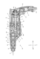
まず、図1を参照して、ハンマドリル101の概略構成について簡単に説明する。図1に示すように、ハンマドリル101の外郭は、主に、本体ハウジング10と、本体ハウジング10に連結されたハンドル17とによって形成されている。 First, the schematic configuration of the hammer drill 101 will be briefly described with reference to FIG. As shown in FIG. 1, the outer shell of the hammer drill 101 is mainly formed by a main body housing 10 and a handle 17 connected to the main body housing 10.

本体ハウジング10は、工具本体または外郭ハウジングとも称される中空体であって、スピンドル31、モータ2、駆動機構5等を収容する。スピンドル31は、長尺の円筒状部材であって、その軸方向の一端部に、先端工具91を取り外し可能に保持するツールホルダ32を備えている。スピンドル31の長軸は、先端工具91の駆動軸A1を規定する。本体ハウジング10は、駆動軸A1に沿って延在する。ツールホルダ32は、駆動軸A1の延在方向(以下、単に駆動軸方向という)における本体ハウジング10の一端部内に配置されている。 The main body housing 10 is a hollow body also called a tool main body or an outer housing, and houses the spindle 31, the motor 2, the drive mechanism 5, and the like. The spindle 31 is a long cylindrical member, and is provided with a tool holder 32 that removably holds the tip tool 91 at one end in the axial direction. The long axis of the spindle 31 defines a drive axis A1 of the tip tool 91. The main body housing 10 extends along the drive axis A1. The tool holder 32 is arranged within one end portion of the main body housing 10 in the extending direction of the drive shaft A1 (hereinafter simply referred to as the drive shaft direction).

ハンドル17は、使用者によって把持される長尺状の中空体である。ハンドル17の軸方向の一端部は、駆動軸方向における本体ハウジング10の他端部(ツールホルダ32が配置されているのとは反対側の端部)に連結されている。ハンドル17は、本体ハウジング10の他端部から突出するように、駆動軸A1に交差する方向(詳細には、概ね直交する方向)に延びている。なお、本実施形態では、本体ハウジング10とハンドル17とは、複数の構成部材がネジ等で連結されることで、一体化されている。ハンドル17の突出端からは、外部の交流電源に接続可能な電源ケーブル179が延出されている。ハンドル17は、使用者によって押圧操作(引き操作)されるトリガ171と、トリガ171の押圧操作に応じてオン状態とされるスイッチ172とを有する。 The handle 17 is an elongated hollow body that is held by a user. One end of the handle 17 in the axial direction is connected to the other end of the main body housing 10 in the drive shaft direction (the end opposite to where the tool holder 32 is disposed). The handle 17 protrudes from the other end of the main body housing 10 and extends in a direction intersecting the drive shaft A1 (more specifically, in a direction substantially perpendicular to the drive shaft A1). In this embodiment, the main body housing 10 and the handle 17 are integrated by connecting a plurality of structural members with screws or the like. A power cable 179 extends from the protruding end of the handle 17 and is connectable to an external AC power source. The handle 17 includes a trigger 171 that is pressed (pulled) by the user, and a switch 172 that is turned on in response to the pressing operation of the trigger 171 .

ハンマドリル101では、スイッチ172がオン状態とされると、モータ2が通電され、駆動機構5が駆動されて、ハンマ動作および/またはドリル動作が行われる。 In the hammer drill 101, when the switch 172 is turned on, the motor 2 is energized, the drive mechanism 5 is driven, and a hammer operation and/or a drill operation are performed.

以下、ハンマドリル101の詳細構成について説明する。なお、以下の説明では、便宜上、駆動軸A1の延在方向(本体ハウジング10の長軸方向)をハンマドリル101の前後方向と規定する。前後方向において、ツールホルダ32が配置されている一端部側をハンマドリル101の前側、反対側(ハンドル17が連結されている側)を後側と規定する。また、駆動軸A1に直交し、且つ、ハンドル17の軸方向に対応する方向をハンマドリル101の上下方向と規定する。上下方向において、本体ハウジング10にハンドル17が連結されている側を上側、ハンドル17の突出端側を下側と規定する。また、前後方向および上下方向に直交する方向を左右方向と規定する。 The detailed configuration of the hammer drill 101 will be described below. In the following description, for convenience, the extending direction of the drive shaft A1 (long axis direction of the main body housing 10) is defined as the front-rear direction of the hammer drill 101. In the front-rear direction, one end side where the tool holder 32 is arranged is defined as the front side of the hammer drill 101, and the opposite side (the side to which the handle 17 is connected) is defined as the rear side. Further, the direction perpendicular to the drive shaft A1 and corresponding to the axial direction of the handle 17 is defined as the vertical direction of the hammer drill 101. In the vertical direction, the side where the handle 17 is connected to the main body housing 10 is defined as an upper side, and the protruding end side of the handle 17 is defined as a lower side. Further, a direction perpendicular to the front-rear direction and the up-down direction is defined as the left-right direction.

まず、本体ハウジング10の構成について説明する。 First, the configuration of the main body housing 10 will be explained.

図1に示すように、本体ハウジング10は、円筒状の前端部を有する。この円筒状の部分を、バレル部131という。本体ハウジング10のうち、バレル部131以外の部分は、概ね矩形箱状に形成されている。バレル部131には、補助ハンドル(図示略)を装着可能である。また、使用者は、ハンドル17に加え、補助ハンドルが装着されていないバレル部131を補助的に把持することも可能である。 As shown in FIG. 1, the main body housing 10 has a cylindrical front end. This cylindrical portion is called a barrel portion 131. A portion of the main body housing 10 other than the barrel portion 131 is formed into a generally rectangular box shape. An auxiliary handle (not shown) can be attached to the barrel portion 131. Further, in addition to the handle 17, the user can also hold the barrel portion 131 to which no auxiliary handle is attached.

本体ハウジング10の内部空間は、本体ハウジング10の内部に配置された軸受支持体15によって2つの領域に区画されている。なお、軸受支持体15は、駆動軸A1に交差するように配置されて、本体ハウジング10の内周に嵌め込まれ、本体ハウジング10によって固定状に(本体ハウジング10に対して移動不能に)保持されている。軸受支持体15の後側の領域は、主としてモータ2を収容するための領域である。軸受支持体15の前側の領域は、主としてスピンドル31および駆動機構5を収容するための領域である。以下、本体ハウジング10のうち、モータ2の収容領域に対応する部分を後部ハウジング11といい、スピンドル31および駆動機構5の収容領域に対応する部分(バレル部131を含む)を前部ハウジング13という。 The internal space of the main body housing 10 is divided into two regions by a bearing support 15 arranged inside the main body housing 10. The bearing support 15 is arranged to intersect with the drive shaft A1, is fitted into the inner periphery of the main body housing 10, and is held fixedly (immovably with respect to the main body housing 10) by the main body housing 10. ing. The region on the rear side of the bearing support 15 is mainly a region for accommodating the motor 2. The front area of the bearing support 15 is primarily an area for accommodating the spindle 31 and the drive mechanism 5. Hereinafter, the part of the main body housing 10 that corresponds to the accommodation area of the motor 2 will be referred to as the rear housing 11, and the part (including the barrel part 131) that corresponds to the accommodation area of the spindle 31 and the drive mechanism 5 will be referred to as the front housing 13. .

後部ハウジング11および前部ハウジング13は、何れも樹脂(プラスチック)製である。後部ハウジング11は、複数の部材が連結されることで形成されている。一方、前部ハウジング13は、単一の筒状部材である。 Both the rear housing 11 and the front housing 13 are made of resin (plastic). The rear housing 11 is formed by connecting a plurality of members. On the other hand, the front housing 13 is a single cylindrical member.

本実施形態では、軸受支持体15も、樹脂(プラスチック)で形成されている。これは、後述する防振構造によって、駆動機構5に生じる振動が、本体ハウジング10や本体ハウジング10に固定状に取り付けられた軸受支持体15へ伝達することが抑制されることから、軸受支持体15には、金属ほどの強度が求められないためである。これにより、軸受支持体15が金属で形成される場合に比べ、ハンマドリル101を軽量化することができる。また、図2に示すように、軸受支持体15は、その外周面の概ね全体が、前部ハウジング13の内周面に接触するように、前部ハウジング13の後端部に嵌め込まれている。 In this embodiment, the bearing support 15 is also made of resin (plastic). This is because the vibration-proofing structure described later suppresses transmission of vibrations generated in the drive mechanism 5 to the main body housing 10 and the bearing support 15 fixedly attached to the main body housing 10. This is because 15 is not required to have as much strength as metal. Thereby, the weight of the hammer drill 101 can be reduced compared to the case where the bearing support body 15 is formed of metal. Further, as shown in FIG. 2, the bearing support 15 is fitted into the rear end of the front housing 13 such that substantially the entire outer peripheral surface thereof contacts the inner peripheral surface of the front housing 13. .

詳細は後述するが、軸受支持体15は、各種シャフトの軸受を支持する部材である。よって、本体ハウジング10の内部に嵌め込まれる外周の寸法には、高い精度が求められる。そこで、このような軸受支持体15を金属(例えば、アルミニウム合金)で形成する場合には、寸法精度のために、単一の円をベースとして加工が行われることが好ましい。これに対し、本実施形態では、軸受支持体15を樹脂で形成することで、形状の自由度が高められている。具体的には、図3に示すように、駆動軸A1に直交する平面における軸受支持体15の断面形状は、単一の円ではなく、3つの円をベースとしたものである。よって、軸受支持体15の外周(つまり、本体ハウジング10との接触部)は、単一の円の円周上にはなく、3つの円の夫々の円周上に、軸受支持体15の外周の一部が重なっている。 Although details will be described later, the bearing support 15 is a member that supports bearings of various shafts. Therefore, high precision is required for the dimensions of the outer periphery to be fitted into the interior of the main body housing 10. Therefore, when such a bearing support body 15 is formed of metal (for example, an aluminum alloy), it is preferable to perform processing based on a single circle for dimensional accuracy. In contrast, in this embodiment, the bearing support body 15 is formed of resin, thereby increasing the degree of freedom in shape. Specifically, as shown in FIG. 3, the cross-sectional shape of the bearing support 15 in a plane perpendicular to the drive shaft A1 is based on three circles instead of a single circle. Therefore, the outer periphery of the bearing support 15 (that is, the contact portion with the main body housing 10) is not on the circumference of a single circle, but on the circumference of each of three circles. Some of them overlap.

図2に示すように、本体ハウジング10の内周面と接する軸受支持体15の外周面には、環状の溝が形成されている。この溝内には、ゴム製のOリング151が装着されている。駆動機構5が収容された前部ハウジング13内には、潤滑剤が配される。Oリング151は、本体ハウジング10と軸受支持体15との間の隙間を塞ぐシール部材として機能し、潤滑剤が、本体ハウジング10と軸受支持体15との間の隙間を通って後部ハウジング11内へ漏れ出るのを防止することができる。なお、シール部材として、軸受支持体15とは別個のOリング151に代えて、例えば、図4に示すように、熱可塑性エラストマ製の弾性体152が、樹脂の軸受支持体15の外周に一体成形されていてもよい。この場合、本体ハウジング10に対し、弾性体152付の軸受支持体15を容易に組み付けることができる。 As shown in FIG. 2, an annular groove is formed on the outer circumferential surface of the bearing support 15 that is in contact with the inner circumferential surface of the main body housing 10. As shown in FIG. A rubber O-ring 151 is installed in this groove. A lubricant is disposed within the front housing 13 in which the drive mechanism 5 is housed. The O-ring 151 functions as a sealing member that closes the gap between the main body housing 10 and the bearing support 15, and the lubricant passes through the gap between the main body housing 10 and the bearing support 15 into the rear housing 11. This can prevent leakage. Note that instead of the O-ring 151 that is separate from the bearing support 15 as a sealing member, for example, as shown in FIG. It may be molded. In this case, the bearing support 15 with the elastic body 152 can be easily assembled to the main body housing 10.

また、図3および図5に示すように、軸受支持体15には、前部ハウジング13内の圧力を後部ハウジング11内の圧力と一致するように調整すべく、前部ハウジング13の内部空間と、後部ハウジング11の内部空間とを連通するエア抜き穴153が設けられている。なお、エア抜き穴153内には、潤滑油がエア抜き穴153を通じて後部ハウジング11内に漏出することを防止するフィルタ154が嵌め込まれている(図17参照)。 As shown in FIGS. 3 and 5, the bearing support 15 is also provided with an inner space of the front housing 13 in order to adjust the pressure in the front housing 13 to match the pressure in the rear housing 11. , an air vent hole 153 communicating with the internal space of the rear housing 11 is provided. Note that a filter 154 is fitted into the air vent hole 153 to prevent lubricating oil from leaking into the rear housing 11 through the air vent hole 153 (see FIG. 17).

以下、本体ハウジング10の内部構造について説明する。 The internal structure of the main body housing 10 will be described below.

まず、モータ2について説明する。本実施形態では、モータ2として、外部の交流電源から供給された電力で駆動される交流モータが採用されている。図1に示すように、モータ2は、ネジによって後部ハウジング11に固定されている。モータ2は、ステータおよびロータを含む本体部20と、ロータと一体的に回転するように構成されたモータシャフト25とを備える。本実施形態では、モータシャフト25の回転軸A2は、駆動軸A1よりも下側で、駆動軸A1と平行に延在する。駆動軸A1および回転軸A2を含む仮想的な平面VP(以下、基準面VPという)(図3および図5参照)は、ハンマドリル101の上下方向に延在する。 First, the motor 2 will be explained. In this embodiment, the motor 2 is an AC motor driven by power supplied from an external AC power source. As shown in FIG. 1, the motor 2 is fixed to the rear housing 11 by screws. The motor 2 includes a main body 20 including a stator and a rotor, and a motor shaft 25 configured to rotate integrally with the rotor. In this embodiment, the rotation axis A2 of the motor shaft 25 is below the drive axis A1 and extends parallel to the drive axis A1. A virtual plane VP (hereinafter referred to as reference plane VP) (see FIGS. 3 and 5) including the drive shaft A1 and the rotation axis A2 extends in the vertical direction of the hammer drill 101.

モータシャフト25は、2つの軸受251および252を介して、本体ハウジング10に対して回転軸A2周りに回転可能に支持されている。前側の軸受251は、軸受支持体15の後面側に保持されており、後側の軸受252は、後部ハウジング11(詳細には、後部ハウジング11内でモータ2を収容するインナハウジング)に保持されている。モータシャフト25のうち、本体部20と前側の軸受251との間の部分には、モータ2を冷却するためのファン27が固定されている。モータシャフト25の前端部は、軸受支持体15を貫通し、前部ハウジング13内に突出している。この前部ハウジング13内に突出する部分には、ピニオンギヤ255が固定されている。 The motor shaft 25 is rotatably supported by the main body housing 10 via two bearings 251 and 252 around a rotation axis A2. The front bearing 251 is held on the rear side of the bearing support 15, and the rear bearing 252 is held on the rear housing 11 (specifically, the inner housing that houses the motor 2 within the rear housing 11). ing. A fan 27 for cooling the motor 2 is fixed to a portion of the motor shaft 25 between the main body 20 and the front bearing 251 . The front end of the motor shaft 25 passes through the bearing support 15 and projects into the front housing 13 . A pinion gear 255 is fixed to a portion protruding into the front housing 13.

次に、モータシャフト25から駆動機構5への動力伝達経路について説明する。 Next, the power transmission path from the motor shaft 25 to the drive mechanism 5 will be explained.

図5および図6に示すように、本実施形態では、ハンマドリル101は、2本の中間シャフト(第1中間シャフト41および第2中間シャフト42)を備えている。そして、駆動機構5は、第1中間シャフト41から伝達された動力によってハンマ動作を遂行し、第2中間シャフト42から伝達された動力によってドリル動作を遂行するように構成されている。つまり、第1中間シャフト41は、ハンマ動作のための動力伝達専用のシャフトである。第2中間シャフト42は、ドリル動作のための動力伝達専用のシャフトである。 As shown in FIGS. 5 and 6, in this embodiment, the hammer drill 101 includes two intermediate shafts (a first intermediate shaft 41 and a second intermediate shaft 42). The drive mechanism 5 is configured to perform a hammer operation using the power transmitted from the first intermediate shaft 41 and perform a drilling operation using the power transmitted from the second intermediate shaft 42. In other words, the first intermediate shaft 41 is a shaft dedicated to power transmission for hammer operation. The second intermediate shaft 42 is a shaft dedicated to power transmission for drilling operations.

第1中間シャフト41および第2中間シャフト42は何れも、前部ハウジング13内で、駆動軸A1および回転軸A2に平行に延在する。第1中間シャフト41は、2つの軸受411および412を介して、本体ハウジング10に対して回転軸A3周りに回転可能に支持されている。前側の軸受411は、前部ハウジング13に保持されており、後側の軸受412は、軸受支持体15の前面側に保持されている。同様に、第2中間シャフト42は、2つの軸受421および422を介して、本体ハウジング10に対して回転軸A4周りに回転可能に支持されている。前側の軸受421は、前部ハウジング13に保持されており、後側の軸受422は、軸受支持体15の前面側に保持されている。上述のように、モータシャフト25の軸受251も軸受支持体15に支持されているため、モータシャフト25、第1中間シャフト41および第2中間シャフト42の間の高精度な配置関係を実現することができる。 Both the first intermediate shaft 41 and the second intermediate shaft 42 extend within the front housing 13 parallel to the drive axis A1 and the rotation axis A2. The first intermediate shaft 41 is rotatably supported by the main body housing 10 via two bearings 411 and 412 around a rotation axis A3. The front bearing 411 is held by the front housing 13, and the rear bearing 412 is held by the front side of the bearing support 15. Similarly, the second intermediate shaft 42 is rotatably supported by the main housing 10 via two bearings 421 and 422 around the rotation axis A4. The front bearing 421 is held by the front housing 13, and the rear bearing 422 is held by the front side of the bearing support 15. As described above, since the bearing 251 of the motor shaft 25 is also supported by the bearing support 15, it is possible to realize a highly accurate arrangement relationship between the motor shaft 25, the first intermediate shaft 41, and the second intermediate shaft 42. I can do it.

第1中間シャフト41は、基準面VPに対して右側に配置されている。第2中間シャフト42は、基準面VPに対して左側に配置されている。これにより、第1中間シャフト41および第2中間シャフト42が左側または右側に偏って配置される場合に比べ、左右方向の重量バランスをよくすることができる。 The first intermediate shaft 41 is arranged on the right side with respect to the reference plane VP. The second intermediate shaft 42 is arranged on the left side with respect to the reference plane VP. Thereby, the weight balance in the left-right direction can be improved compared to the case where the first intermediate shaft 41 and the second intermediate shaft 42 are arranged biased to the left side or the right side.

また、駆動軸A1に直交する平面上において、モータシャフト25の回転軸A2と第1中間シャフト41の回転軸A3とを結ぶ線分と、回転軸A2と第2中間シャフト42の回転軸A4とを結ぶ線分とがなす角は、鈍角である。このような配置により、モータシャフト25のピニオンギヤ255には、第1被動ギヤ414および第2被動ギヤ424が、概ね反対方向から噛合することになる。これにより、ピニオンギヤ255に、特定の1方向の曲げ荷重がかかるのを抑制することができる。また、第1被動ギヤ414および第2被動ギヤ424がピニオンギヤ255を中心として一直線上に並ぶ場合に比べ、駆動機構5全体がその直線の方向に大型化することを抑制しつつ、第1中間シャフト41および第2中間シャフト42上に、必要な部品を合理的に配置することができる。 Furthermore, on a plane perpendicular to the drive shaft A1, a line segment connecting the rotation axis A2 of the motor shaft 25 and the rotation axis A3 of the first intermediate shaft 41, and a line segment connecting the rotation axis A2 and the rotation axis A4 of the second intermediate shaft 42 are connected. The angle formed by the line segment connecting is an obtuse angle. With this arrangement, the first driven gear 414 and the second driven gear 424 mesh with the pinion gear 255 of the motor shaft 25 from generally opposite directions. Thereby, it is possible to suppress a bending load from being applied to the pinion gear 255 in one specific direction. Moreover, compared to the case where the first driven gear 414 and the second driven gear 424 are arranged in a straight line with the pinion gear 255 as the center, the first intermediate shaft 41 and the second intermediate shaft 42, necessary parts can be reasonably arranged.

第1中間シャフト41の後端部には、軸受412の前側に隣接して、第1被動ギヤ414が固定されている。第1被動ギヤ414は、ピニオンギヤ255に噛合している。 A first driven gear 414 is fixed to the rear end of the first intermediate shaft 41 adjacent to the front side of the bearing 412 . The first driven gear 414 meshes with the pinion gear 255.

第2中間シャフト42の後端部には、軸受422の前側に隣接して、第2被動ギヤ424を有するギヤ部材423が配置されている。なお、ギヤ部材423は、円筒状に形成され、第2中間シャフト42(詳細には、後述の駆動側部材74)の外周側に配置されている。なお、ギヤ部材423の円筒状の前端部の外周には、スプライン部425が設けられている。スプライン部425は、回転軸A4方向(前後方向)に延在する複数のスプライン(外歯)を有する。詳細は後述するが、第2被動ギヤ424(ギヤ部材423)の回転は、第2伝達部材72およびトルクリミッタ73を介して第2中間シャフト42に伝達される。 A gear member 423 having a second driven gear 424 is arranged at the rear end of the second intermediate shaft 42 adjacent to the front side of the bearing 422 . Note that the gear member 423 is formed in a cylindrical shape and is arranged on the outer peripheral side of the second intermediate shaft 42 (specifically, the drive-side member 74 to be described later). Note that a spline portion 425 is provided on the outer periphery of the cylindrical front end portion of the gear member 423. The spline portion 425 has a plurality of splines (external teeth) extending in the direction of the rotation axis A4 (front-back direction). Although details will be described later, the rotation of the second driven gear 424 (gear member 423) is transmitted to the second intermediate shaft 42 via the second transmission member 72 and torque limiter 73.

このように、本実施形態では、モータシャフト25から分岐する2つの動力伝達経路が設けられており、これらの経路の夫々が、ハンマ動作専用の動力伝達経路およびドリル動作専用の動力伝達経路として用いられる。 In this way, in this embodiment, two power transmission paths are provided that branch from the motor shaft 25, and each of these paths is used as a power transmission path dedicated to hammer operation and a power transmission path dedicated to drill operation. It will be done.

スピンドル31について説明する。スピンドル31は、ハンマドリル101の最終出力シャフトである。図2に示すように、スピンドル31は、駆動軸A1に沿って、前部ハウジング13内に配置され、本体ハウジング10に対して駆動軸A1周りに回転可能に支持されている。スピンドル31は、長尺状の段付きの円筒部材として構成されている。 The spindle 31 will be explained. Spindle 31 is the final output shaft of hammer drill 101. As shown in FIG. 2, the spindle 31 is disposed within the front housing 13 along the drive axis A1, and is rotatably supported by the main body housing 10 around the drive axis A1. The spindle 31 is configured as an elongated stepped cylindrical member.

スピンドル31の前半部分は、先端工具91を着脱可能なツールホルダ32を構成する。先端工具91は、その長軸が駆動軸A1と一致するように、ツールホルダ32の前端部のビット挿入孔330に挿入され、ツールホルダ32に対する軸方向の移動が許容され、軸周りの回転が規制された状態で保持される。スピンドル31の後半部分は、後述するピストン65を摺動可能に保持するシリンダ33を構成する。本実施形態では、スピンドル31は、ツールホルダ32とシリンダ33とが一体的に形成された単一部材であるが、複数の部材が連結されることで形成されていてもよい。なお、スピンドル31は、鉄(または鉄を主成分とする合金)で形成されている。スピンドル31は、バレル部131内で保持された軸受316と、後述の可動支持体18に保持された軸受317によって支持されている。 The first half of the spindle 31 constitutes a tool holder 32 to which a tip tool 91 can be attached and detached. The tip tool 91 is inserted into the bit insertion hole 330 at the front end of the tool holder 32 so that its long axis coincides with the drive axis A1, and is allowed to move in the axial direction with respect to the tool holder 32 and rotate around the axis. kept in a regulated state. The latter half of the spindle 31 constitutes a cylinder 33 that slidably holds a piston 65, which will be described later. In this embodiment, the spindle 31 is a single member in which the tool holder 32 and the cylinder 33 are integrally formed, but it may be formed by connecting a plurality of members. Note that the spindle 31 is made of iron (or an alloy whose main component is iron). The spindle 31 is supported by a bearing 316 held within the barrel portion 131 and a bearing 317 held by a movable support 18, which will be described later.

以下、駆動機構5について説明する。図6~図8に示すように、本実施形態では、駆動機構5は、打撃機構6と、回転伝達機構7とを含む。打撃機構6は、ハンマ動作を遂行するための機構であって、第1中間シャフト41の回転運動を直線運動に変換し、先端工具91を駆動軸A1に沿って直線状に駆動するように構成されている。回転伝達機構7は、ドリル動作を遂行するための機構であって、第2中間シャフト42の回転運動をスピンドル31に伝達し、先端工具91を駆動軸A1周りに回転駆動するように構成されている。以下、打撃機構6および回転伝達機構7の詳細構成について、順に説明する。 The drive mechanism 5 will be explained below. As shown in FIGS. 6 to 8, in this embodiment, the drive mechanism 5 includes a striking mechanism 6 and a rotation transmission mechanism 7. The striking mechanism 6 is a mechanism for performing a hammer operation, and is configured to convert the rotational motion of the first intermediate shaft 41 into linear motion, and drive the tip tool 91 linearly along the drive axis A1. has been done. The rotation transmission mechanism 7 is a mechanism for performing a drilling operation, and is configured to transmit the rotational movement of the second intermediate shaft 42 to the spindle 31 to rotate the tip tool 91 around the drive axis A1. There is. Hereinafter, detailed configurations of the striking mechanism 6 and the rotation transmission mechanism 7 will be explained in order.

本実施形態では、図6および図7に示すように、打撃機構6は、運動変換部材61と、ピストン65と、ストライカ67と、インパクトボルト68とを含む。 In this embodiment, as shown in FIGS. 6 and 7, the striking mechanism 6 includes a motion conversion member 61, a piston 65, a striker 67, and an impact bolt 68.

運動変換部材61は、第1中間シャフト41上に配置され、第1中間シャフト41の回転運動を直線運動に変換してピストン65に伝達するように構成されている。より詳細には、運動変換部材61は、回転体611と、揺動部材616とを含む。回転体611は、軸受614によって、本体ハウジング10に対して回転軸A3周りに回転可能に支持されている。揺動部材616は、回転体611の外周に回転可能に取り付けられ、回転体611の回転に伴って、回転軸A3の延在方向(前後方向)に揺動するように構成されている。揺動部材616は、回転体611から上方に延びるアーム部617を有する。 The motion converting member 61 is disposed on the first intermediate shaft 41 and is configured to convert the rotational motion of the first intermediate shaft 41 into a linear motion and transmit the linear motion to the piston 65. More specifically, the motion converting member 61 includes a rotating body 611 and a swinging member 616. The rotating body 611 is rotatably supported by a bearing 614 with respect to the main body housing 10 around a rotation axis A3. The swinging member 616 is rotatably attached to the outer periphery of the rotating body 611, and is configured to swing in the extending direction (back and forth direction) of the rotating shaft A3 as the rotating body 611 rotates. The swinging member 616 has an arm portion 617 extending upward from the rotating body 611.

ピストン65は、有底円筒状の部材であって、スピンドル31のシリンダ33内に、駆動軸A1に沿って摺動可能に配置されている。ピストン65は、連結ピンを介して揺動部材616のアーム部617に連結されており、揺動部材616の揺動に伴って前後方向に往復動される。 The piston 65 is a cylindrical member with a bottom, and is disposed within the cylinder 33 of the spindle 31 so as to be slidable along the drive shaft A1. The piston 65 is connected to an arm portion 617 of a swinging member 616 via a connecting pin, and is reciprocated in the front-back direction as the swinging member 616 swings.

ストライカ67は、先端工具91に打撃力を加えるための打撃子である。ストライカ67は、ピストン65内に、駆動軸A1に沿って摺動可能に配置されている。ストライカ67の後側のピストン65の内部空間は、空気バネとして機能する空気室として規定されている。インパクトボルト68は、ストライカ67の運動エネルギを先端工具91に伝達する中間子である。インパクトボルト68は、ツールホルダ32内で、ストライカ67の前側に、駆動軸A1に沿って移動可能に配置されている。なお、本実施形態では、インパクトボルト68は、ツールホルダ32内に配置されたガイドスリーブ36および規制リング35によって、前後方向に摺動可能に保持されている。 The striker 67 is a striker for applying striking force to the tip tool 91. The striker 67 is disposed within the piston 65 so as to be slidable along the drive shaft A1. The internal space of the piston 65 on the rear side of the striker 67 is defined as an air chamber that functions as an air spring. The impact bolt 68 is an intermediate that transmits the kinetic energy of the striker 67 to the tip tool 91. The impact bolt 68 is disposed in the tool holder 32 in front of the striker 67 so as to be movable along the drive shaft A1. In addition, in this embodiment, the impact bolt 68 is held by the guide sleeve 36 and the regulation ring 35 arranged in the tool holder 32 so as to be slidable in the front-rear direction.

揺動部材616の揺動に伴って、ピストン65が前後方向に移動されると、空気室の空気の圧力が変動し、空気バネの作用によってストライカ67がピストン65内を前後方向に摺動する。より詳細には、ピストン65が前方に向けて移動されると、空気室の空気が圧縮されて内圧が上昇する。ストライカ67は、空気バネの作用で高速に前方に押し出されてインパクトボルト68を打撃する。インパクトボルト68は、ストライカ67の運動エネルギを先端工具91に伝達する。これにより、先端工具91は駆動軸A1に沿って直線状に駆動される。一方、ピストン65が後方へ移動されると、空気室の空気が膨張して内圧が低下し、ストライカ67が後方へ引き込まれる。先端工具91は、被加工物への押し付けにより、インパクトボルト68と共に後方へ移動する。このようにして、打撃機構6によってハンマ動作が繰り返される。 When the piston 65 is moved back and forth as the swinging member 616 swings, the pressure of the air in the air chamber fluctuates, and the striker 67 slides inside the piston 65 in the back and forth direction due to the action of the air spring. . More specifically, when the piston 65 is moved forward, the air in the air chamber is compressed and the internal pressure increases. The striker 67 is pushed forward at high speed by the action of the air spring and strikes the impact bolt 68. The impact bolt 68 transmits the kinetic energy of the striker 67 to the tip tool 91. Thereby, the tip tool 91 is linearly driven along the drive axis A1. On the other hand, when the piston 65 is moved rearward, the air in the air chamber expands, the internal pressure decreases, and the striker 67 is drawn rearward. The tip tool 91 moves rearward together with the impact bolt 68 by being pressed against the workpiece. In this way, the hammering action is repeated by the striking mechanism 6.

本実施形態では、第1中間シャフト41の回転運動は、第1伝達部材64および介在部材63を介して運動変換部材61(詳細には、回転体611)に伝達される。以下、介在部材63および第1伝達部材64について、順に説明する。 In this embodiment, the rotational motion of the first intermediate shaft 41 is transmitted to the motion conversion member 61 (specifically, the rotating body 611) via the first transmission member 64 and the intervening member 63. Hereinafter, the intervening member 63 and the first transmission member 64 will be explained in order.

図6および図9に示すように、介在部材63は、第1中間シャフト41と同軸状に、第1中間シャフト41の周囲に配置され、第1中間シャフト41と運動変換部材61(詳細には、回転体611)との間に介在する円筒状の部材である。介在部材63は、第1中間シャフト41に対して前後方向に移動不能である一方、第1中間シャフト41に対して回転軸A3周りには回転可能である。 As shown in FIGS. 6 and 9, the intervening member 63 is disposed coaxially with the first intermediate shaft 41 and around the first intermediate shaft 41, and is connected to the first intermediate shaft 41 and the motion converting member 61 (in detail). , a rotating body 611). The intervening member 63 is immovable in the front-back direction with respect to the first intermediate shaft 41, but is rotatable with respect to the first intermediate shaft 41 around the rotation axis A3.

より詳細には、第1中間シャフト41の前端部(前側の軸受411後側に隣接する部分)は、最大の外径を有する最大径部として構成されている。最大径部の外周には、スプライン部416が設けられている。スプライン部416は、回転軸A3方向(前後方向)に延在する複数のスプライン(外歯)を有する。介在部材63は、スプライン部416と、第1中間シャフト41の後端部に固定された第1被動ギヤ414との間に、前後方向に移動不能に保持されている。なお、第1中間シャフト41のうち、スプライン部416の後側に隣接する部分は、それより更に後側の部分に比べて僅かに大きい外径を有する大径部417として構成されている。 More specifically, the front end portion of the first intermediate shaft 41 (the portion adjacent to the rear side of the front bearing 411) is configured as the largest diameter portion having the largest outer diameter. A spline portion 416 is provided on the outer periphery of the maximum diameter portion. The spline portion 416 has a plurality of splines (external teeth) extending in the direction of the rotation axis A3 (front-back direction). The intervening member 63 is held between the spline portion 416 and the first driven gear 414 fixed to the rear end of the first intermediate shaft 41 so as not to be movable in the front-rear direction. Note that a portion of the first intermediate shaft 41 adjacent to the rear side of the spline portion 416 is configured as a large diameter portion 417 having a slightly larger outer diameter than a portion further rearward.

また、介在部材63の外周には、介在部材63の概ね全長に亘るスプライン部631が設けられている。スプライン部631は、回転軸A3方向(前後方向)に延在する複数のスプライン(外歯)を有する。なお、介在部材63のスプライン部631の径は、第1中間シャフト41のスプライン部416の径よりも大きい。 Furthermore, a spline portion 631 is provided on the outer periphery of the intervening member 63 and extends over approximately the entire length of the intervening member 63. The spline portion 631 has a plurality of splines (external teeth) extending in the direction of the rotation axis A3 (front-back direction). Note that the diameter of the spline portion 631 of the intervening member 63 is larger than the diameter of the spline portion 416 of the first intermediate shaft 41.

一方、回転体611の内周には、スプライン部612が形成されている。スプライン部612は、スプライン部631に係合するスプライン(内歯)を有する。介在部材63は、回転体611と常にスプライン係合しており、回転体611によって保持されている。このような構成により、回転体611は、介在部材63および第1中間シャフト41に対して回転軸A3方向(前後方向)に移動可能、且つ、介在部材63と一体的に回転可能とされている。 On the other hand, a spline portion 612 is formed on the inner circumference of the rotating body 611. The spline portion 612 has splines (internal teeth) that engage with the spline portion 631 . The intervening member 63 is always in spline engagement with the rotating body 611 and is held by the rotating body 611. With such a configuration, the rotating body 611 is movable in the rotation axis A3 direction (back and forth direction) with respect to the intervening member 63 and the first intermediate shaft 41, and is also rotatable integrally with the intervening member 63. .

第1伝達部材64は、第1中間シャフト41上に配置され、第1中間シャフト41と一体的に回転可能、且つ、第1中間シャフト41および介在部材63に対して回転軸A3方向(前後方向)に移動可能に構成されている。 The first transmission member 64 is disposed on the first intermediate shaft 41, is rotatable integrally with the first intermediate shaft 41, and is rotated in the rotation axis A3 direction (front-back direction) with respect to the first intermediate shaft 41 and the intervening member 63. ) is configured to be movable.

より詳細には、第1伝達部材64は、第1中間シャフト41の周囲に配置された略円筒状の部材であって、第1伝達部材64の内周には、第1スプライン部641と、第2スプライン部642とが設けられている。 More specifically, the first transmission member 64 is a substantially cylindrical member disposed around the first intermediate shaft 41, and has a first spline portion 641 on the inner periphery of the first transmission member 64, A second spline portion 642 is provided.

第1スプライン部641は、第1伝達部材64の後端部に設けられている。第1スプライン部641は、介在部材63のスプライン部631に係合可能な複数のスプライン(内歯)を有する。なお、上述のように、介在部材63のスプライン部631は、回転体611のスプライン部612とも係合している。つまり、スプライン部631は、回転体611および第1伝達部材64の2つの部材との係合に有効に利用されている。第2スプライン部642は、第1伝達部材64の前半部分に設けられている。第2スプライン部642は、第1中間シャフト41のスプライン部416に常に係合する複数のスプライン(内歯)を有する。 The first spline portion 641 is provided at the rear end portion of the first transmission member 64. The first spline portion 641 has a plurality of splines (internal teeth) that can be engaged with the spline portion 631 of the intervening member 63. Note that, as described above, the spline portion 631 of the intervening member 63 also engages with the spline portion 612 of the rotating body 611. In other words, the spline portion 631 is effectively used for engagement with the two members, the rotating body 611 and the first transmission member 64. The second spline portion 642 is provided in the front half of the first transmission member 64. The second spline portion 642 has a plurality of splines (internal teeth) that always engage with the spline portion 416 of the first intermediate shaft 41 .

このような構成により、図9に実線で示すように、前後方向において、第1スプライン部641が介在部材63のスプライン部631と係合する位置(以下、係合位置という)に配置されている場合、第1伝達部材64は、介在部材63と一体的に回転可能、つまり、第1中間シャフト41から介在部材63へ動力を伝達可能である。本実施形態では、第1スプライン部641の径は、第2スプライン部642の径よりも大きい。このように、第1スプライン部641を大径とすることで、効率的なトルク伝達を行うことができる。 With such a configuration, as shown by the solid line in FIG. 9, the first spline portion 641 is disposed at a position where it engages with the spline portion 631 of the intervening member 63 (hereinafter referred to as the engagement position) in the front-rear direction. In this case, the first transmission member 64 can rotate integrally with the intervening member 63, that is, can transmit power from the first intermediate shaft 41 to the intervening member 63. In this embodiment, the diameter of the first spline section 641 is larger than the diameter of the second spline section 642. In this way, by making the first spline portion 641 large in diameter, efficient torque transmission can be performed.

一方、図9に点線で示すように、第1スプライン部641がスプライン部631から離間する(係合不能な)位置(以下、離間位置という)に配置されている場合、第1伝達部材64は、第1中間シャフト41から介在部材63への動力伝達を不能とする(遮断する)。 On the other hand, as shown by the dotted line in FIG. 9, when the first spline part 641 is disposed in a position where it is separated from the spline part 631 (hereinafter referred to as the separated position), the first transmission member 64 is , disables (blocks) power transmission from the first intermediate shaft 41 to the intervening member 63.

なお、第1中間シャフト41のうち、大径部417の径は、介在部材63の内径よりも僅かに小さく設定されている。このため、介在部材63の内周と、第1中間シャフト41の大径部417の外周との間の隙間は微小である。これにより、第1伝達部材64が離間位置から係合位置へ移動するときに、第2スプライン部642とスプライン部631とのスムーズな係合を実現することができる。一方、介在部材63の内周と、大径部417以外の部分の外周との間には、より大きな隙間が確保されている。これにより、第1中間シャフト41から介在部材63への動力伝達が遮断されているときに、第1中間シャフト41と介在部材63との共回りをより確実に抑制することができる。 Note that the diameter of the large diameter portion 417 of the first intermediate shaft 41 is set to be slightly smaller than the inner diameter of the intervening member 63. Therefore, the gap between the inner circumference of the intervening member 63 and the outer circumference of the large diameter portion 417 of the first intermediate shaft 41 is minute. Thereby, when the first transmission member 64 moves from the separated position to the engaged position, smooth engagement between the second spline part 642 and the spline part 631 can be realized. On the other hand, a larger gap is ensured between the inner periphery of the intervening member 63 and the outer periphery of the portion other than the large diameter portion 417. Thereby, when the power transmission from the first intermediate shaft 41 to the intervening member 63 is interrupted, it is possible to more reliably suppress the first intermediate shaft 41 and the intervening member 63 from rotating together.

以上に説明したように、本実施形態では、第1伝達部材64および介在部材63は、ハンマ動作のための動力を伝達または遮断する第1クラッチ機構62として機能する。なお、本実施形態では、第1伝達部材64は、モード切替機構80(図12参照)に接続されており、使用者によるモード切替ダイヤル800(図2参照)の操作に応じて係合位置と離間位置の間で移動される。つまり、第1クラッチ機構62は、モード切替ダイヤル800の操作に応じて、動力伝達状態と遮断状態の間で切り替えられる。なお、モード切替機構80については、後で詳述する。 As described above, in this embodiment, the first transmission member 64 and the intervening member 63 function as the first clutch mechanism 62 that transmits or interrupts power for the hammer operation. Note that in this embodiment, the first transmission member 64 is connected to a mode switching mechanism 80 (see FIG. 12), and is switched between the engagement position and the engaged position according to the user's operation of the mode switching dial 800 (see FIG. 2). moved between separate positions. That is, the first clutch mechanism 62 is switched between the power transmission state and the cutoff state according to the operation of the mode switching dial 800. Note that the mode switching mechanism 80 will be described in detail later.

図8に示すように、本実施形態では、回転伝達機構7は、駆動ギヤ78と、被動ギヤ79とを含む。駆動ギヤ78は、第2中間シャフト42の前端部(前側の軸受421の後側に隣接する部分)に固定されている。被動ギヤ79は、スピンドル31のシリンダ33の外周に固定され、駆動ギヤ78に噛合している。駆動ギヤ78および被動ギヤ79は、ギヤ減速機構を構成する。第2中間シャフト42と一体的に駆動ギヤ78が回転するのに伴って、被動ギヤ79と一体的にスピンドル31が回転される。これにより、ツールホルダ32に保持された先端工具91が駆動軸A1周りに回転駆動されるドリル動作が遂行される。 As shown in FIG. 8, in this embodiment, the rotation transmission mechanism 7 includes a drive gear 78 and a driven gear 79. The drive gear 78 is fixed to the front end portion of the second intermediate shaft 42 (the portion adjacent to the rear side of the front bearing 421). The driven gear 79 is fixed to the outer periphery of the cylinder 33 of the spindle 31 and meshes with the drive gear 78. Drive gear 78 and driven gear 79 constitute a gear reduction mechanism. As the driving gear 78 rotates integrally with the second intermediate shaft 42, the spindle 31 rotates integrally with the driven gear 79. As a result, a drilling operation is performed in which the tip tool 91 held by the tool holder 32 is rotationally driven around the drive shaft A1.

なお、上述のように、本実施形態では、モータシャフト25の回転に伴って回転される第2被動ギヤ424の回転運動は、第2伝達部材72およびトルクリミッタ73を介して第2中間シャフト42に伝達される。以下、トルクリミッタ73および第2伝達部材72について、順に説明する。 As described above, in this embodiment, the rotational movement of the second driven gear 424 rotated with the rotation of the motor shaft 25 is transferred to the second intermediate shaft 42 via the second transmission member 72 and the torque limiter 73. transmitted to. Hereinafter, the torque limiter 73 and the second transmission member 72 will be explained in order.

図6および図10に示すように、トルクリミッタ73は、第2中間シャフト42上に配置され、第2中間シャフト42に作用するトルクが閾値を超える場合、伝達を遮断するように構成された安全クラッチ機構である。本実施形態では、トルクリミッタ73は、駆動側部材74と、被動側部材75と、ボール76と、付勢バネ77とを含む。 As shown in FIGS. 6 and 10, the torque limiter 73 is arranged on the second intermediate shaft 42 and configured to cut off transmission when the torque acting on the second intermediate shaft 42 exceeds a threshold value. It is a clutch mechanism. In this embodiment, the torque limiter 73 includes a driving side member 74, a driven side member 75, a ball 76, and a biasing spring 77.

駆動側部材74は、円筒状の部材であって、第2中間シャフト42の後半部分によって回転可能に支持されている。第2被動ギヤ424は、駆動側部材74の後端部によって回転可能に支持されている。よって、駆動側部材74は、第2中間シャフト42および第2被動ギヤ424に対して回転軸A4周りに回転可能である。 The drive-side member 74 is a cylindrical member, and is rotatably supported by the latter half of the second intermediate shaft 42 . The second driven gear 424 is rotatably supported by the rear end portion of the drive side member 74. Therefore, the drive side member 74 is rotatable around the rotation axis A4 with respect to the second intermediate shaft 42 and the second driven gear 424.

駆動側部材74は、カム凹部742(図11参照)とスプライン部743とを含む。カム凹部742は、駆動側部材74の前端に設けられており、周方向に傾斜するカム面を有する。スプライン部743は、カム凹部742の後側で駆動側部材74の外周に設けられており、回転軸A4方向(前後方向)に延在する複数のスプライン(外歯)を有する。 The drive side member 74 includes a cam recess 742 (see FIG. 11) and a spline portion 743. The cam recess 742 is provided at the front end of the drive side member 74 and has a cam surface that is inclined in the circumferential direction. The spline portion 743 is provided on the outer periphery of the drive side member 74 on the rear side of the cam recess 742, and has a plurality of splines (external teeth) extending in the direction of the rotation axis A4 (front-back direction).

被動側部材75は、円筒状の部材であって、駆動側部材74の前側で、第2中間シャフト42の周囲に配置されている。被動側部材75の内周には、回転軸A4方向(前後方向)に延在する溝751が周方向に複数設けられている。また、第2中間シャフト42の外周には、回転軸A4方向(前後方向)に延在する溝426が周方向に複数設けられている。ボール76は、溝426と溝751とによって規定される軌道内に、転動可能に収容されている。これにより、被動側部材75は、径方向および周方向において、ボール76を介して第2中間シャフト42と係合し、第2中間シャフト42と一体的に回転可能とされている。また、被動側部材75は、ボール76が軌道内を転動可能な範囲で、第2中間シャフト42に対して前後方向に移動可能である。 The driven member 75 is a cylindrical member, and is arranged around the second intermediate shaft 42 in front of the driving member 74 . A plurality of grooves 751 are provided in the inner periphery of the driven member 75 in the circumferential direction, extending in the direction of the rotation axis A4 (front-back direction). Further, on the outer periphery of the second intermediate shaft 42, a plurality of grooves 426 are provided in the circumferential direction, which extend in the direction of the rotation axis A4 (front-back direction). Ball 76 is rotatably housed within a track defined by groove 426 and groove 751. Thereby, the driven member 75 engages with the second intermediate shaft 42 via the ball 76 in the radial direction and the circumferential direction, and is rotatable integrally with the second intermediate shaft 42 . Further, the driven side member 75 is movable in the front-rear direction with respect to the second intermediate shaft 42 within a range in which the balls 76 can roll within the orbit.

被動側部材75は、後端に設けられたカム突起752(図11参照)を有する。カム突起752は、駆動側部材74のカム凹部742に概ね整合する形状を有し、周方向に傾斜するカム面を有する。付勢バネ77は、圧縮コイルバネであって、駆動ギヤ78と被動側部材75の間に、圧縮された状態で配置されている。このため、付勢バネ77は、被動側部材75を、駆動側部材74に近接する方向、つまり、カム突起752とカム凹部742とが噛合う方向(後方)に常に付勢している。カム突起752とカム凹部742とが噛合い係合している場合、駆動側部材74から被動側部材75へのトルク伝達、ひいては第2中間シャフト42の回転が可能となる。なお、駆動側部材74およびギヤ部材423は、被動側部材75を介して後方に付勢され、第2中間シャフト42に対して最後方位置で保持されている。 The driven member 75 has a cam projection 752 (see FIG. 11) provided at the rear end. The cam protrusion 752 has a shape that generally matches the cam recess 742 of the drive side member 74, and has a cam surface that is inclined in the circumferential direction. The biasing spring 77 is a compression coil spring, and is disposed between the drive gear 78 and the driven member 75 in a compressed state. Therefore, the biasing spring 77 always biases the driven member 75 in the direction toward the driving member 74, that is, in the direction in which the cam protrusion 752 and the cam recess 742 engage (backward). When the cam protrusion 752 and the cam recess 742 mesh with each other, torque transmission from the driving side member 74 to the driven side member 75, and thus rotation of the second intermediate shaft 42, becomes possible. Note that the driving side member 74 and the gear member 423 are urged rearward via the driven side member 75 and are held at the rearmost position with respect to the second intermediate shaft 42 .

第2中間シャフト42の回転中に、先端工具91がロックする等の理由で、ツールホルダ32(スピンドル31)を介して第2中間シャフト42に閾値以上の負荷がかかると、図11に示すように、カム突起752とカム凹部742の噛み合い係合が解除される。より詳細には、カム突起752およびカム凹部742のカム面(傾斜面)の作用により、付勢バネ77の付勢力に抗して、カム突起752がカム凹部742から離脱して駆動側部材74の前端面に乗り上げる。つまり、被動側部材75は、駆動側部材74から離間する方向(前方)に移動する。このとき、第2中間シャフト42との間で転動するボール76に案内され、被動側部材75は前方へスムーズに移動することができる。この結果、駆動側部材74から被動側部材75へのトルク伝達が遮断され、第2中間シャフト42の回転が中断される。 If a load exceeding a threshold is applied to the second intermediate shaft 42 via the tool holder 32 (spindle 31) due to the tip tool 91 locking while the second intermediate shaft 42 is rotating, as shown in FIG. Then, the meshing engagement between the cam projection 752 and the cam recess 742 is released. More specifically, due to the action of the cam protrusion 752 and the cam surface (slanted surface) of the cam recess 742, the cam protrusion 752 separates from the cam recess 742 against the urging force of the urging spring 77, and the drive side member 74 rides on the front end surface of the In other words, the driven member 75 moves in a direction away from the driving member 74 (forward). At this time, the driven member 75 can smoothly move forward as guided by the ball 76 rolling between it and the second intermediate shaft 42 . As a result, torque transmission from the driving side member 74 to the driven side member 75 is cut off, and the rotation of the second intermediate shaft 42 is interrupted.

図6および図10に示すように、第2伝達部材72は、第2中間シャフト42上に配置され、トルクリミッタ73の駆動側部材74と一体的に回転可能、且つ、駆動側部材74およびギヤ部材423に対して回転軸A4方向(前後方向)に移動可能に構成されている。 As shown in FIGS. 6 and 10, the second transmission member 72 is disposed on the second intermediate shaft 42, is rotatable integrally with the drive side member 74 of the torque limiter 73, and is connected to the drive side member 74 and the gear. It is configured to be movable relative to the member 423 in the rotation axis A4 direction (back and forth direction).

より詳細には、第2伝達部材72は、駆動側部材74の周囲に配置された略円筒状の部材であって、第2伝達部材72の内周には、第1スプライン部721と、第2スプライン部722とが設けられている。第1スプライン部721は、第2伝達部材72の前半部分に設けられている。第1スプライン部721は、駆動側部材74のスプライン部743に常に係合する複数のスプライン(内歯)を有する。第2スプライン部722は、第2伝達部材72の後端部に設けられており、第1スプライン部721よりも大きい内径を有する。第2スプライン部722は、ギヤ部材423のスプライン部425に係合可能な複数のスプライン(内歯)を有する。 More specifically, the second transmission member 72 is a substantially cylindrical member disposed around the drive side member 74, and has a first spline portion 721 and a first spline portion 721 on the inner periphery of the second transmission member 72. 2 spline portion 722 is provided. The first spline portion 721 is provided in the front half of the second transmission member 72. The first spline portion 721 has a plurality of splines (internal teeth) that always engage with the spline portion 743 of the drive side member 74. The second spline portion 722 is provided at the rear end of the second transmission member 72 and has a larger inner diameter than the first spline portion 721 . The second spline portion 722 has a plurality of splines (internal teeth) that can be engaged with the spline portion 425 of the gear member 423.

このような構成により、図10に実線で示すように、前後方向において、第2スプライン部722がギヤ部材423のスプライン部425と係合する位置(以下、係合位置という)に配置されている場合、第2伝達部材72は、ギヤ部材423と一体的に回転可能である。よって、第2伝達部材72にスプライン係合された駆動側部材74も、ギヤ部材423と一体的に回転可能である。一方、図10に点線で示すように、第2スプライン部722がスプライン部425から離間する(係合不能な)位置(以下、離間位置という)に配置されている場合、第2伝達部材72は、ギヤ部材423から駆動側部材74への動力伝達を不能とする(遮断する)。 With such a configuration, as shown by the solid line in FIG. 10, the second spline portion 722 is located at a position where it engages with the spline portion 425 of the gear member 423 (hereinafter referred to as the engagement position) in the front-rear direction. In this case, the second transmission member 72 is rotatable integrally with the gear member 423. Therefore, the drive side member 74 spline-engaged with the second transmission member 72 is also rotatable integrally with the gear member 423. On the other hand, as shown by the dotted lines in FIG. , disables (cuts off) power transmission from the gear member 423 to the drive side member 74.

以上に説明したように、本実施形態では、第2伝達部材72およびギヤ部材423は、ドリル動作のための動力を伝達または遮断する第2クラッチ機構71として機能する。なお、本実施形態では、第2伝達部材72は、第1伝達部材64と同様、モード切替機構80(図12参照)に接続されており、使用者によるモード切替ダイヤル800(図2参照)の操作に応じて係合位置と離間位置の間で移動される。つまり、第2クラッチ機構71も、第1クラッチ機構62と同様、モード切替ダイヤル800の操作に応じて、動力伝達状態と遮断状態の間で切り替えられる。 As described above, in this embodiment, the second transmission member 72 and the gear member 423 function as the second clutch mechanism 71 that transmits or interrupts power for the drilling operation. In this embodiment, like the first transmission member 64, the second transmission member 72 is connected to the mode switching mechanism 80 (see FIG. 12), and when the user turns the mode switching dial 800 (see FIG. 2). It is moved between an engaged position and a separated position depending on the operation. That is, like the first clutch mechanism 62, the second clutch mechanism 71 is also switched between the power transmission state and the cutoff state according to the operation of the mode switching dial 800.

以下、モード切替ダイヤル800およびモード切替機構80について説明する。 The mode switching dial 800 and the mode switching mechanism 80 will be explained below.

図12~図14に示すように、モード切替機構80は、モード切替ダイヤル800に連動して、ハンマドリル101の動作モードを切り替えるように構成された機構である。本実施形態では、ハンマドリル101は、ハンマドリルモード、ハンマモード、およびドリルモードの3つの動作モードを有する。ハンマドリルモードは、打撃機構6および回転伝達機構7の両方が駆動されることで、ハンマ動作およびドリル動作が行われる動作モードである。ハンマモードは、第2クラッチ機構71によってドリル動作のための動力伝達が遮断され、打撃機構6のみが駆動されることで、ハンマ動作のみが行われる動作モードである。ドリルモードは、第1クラッチ機構62によってハンマ動作のための動力伝達が遮断され、回転伝達機構7のみが駆動されることで、ドリル動作のみが行われる動作モードである。 As shown in FIGS. 12 to 14, the mode switching mechanism 80 is a mechanism configured to switch the operation mode of the hammer drill 101 in conjunction with the mode switching dial 800. In this embodiment, the hammer drill 101 has three operating modes: hammer drill mode, hammer mode, and drill mode. The hammer drill mode is an operation mode in which both the impact mechanism 6 and the rotation transmission mechanism 7 are driven to perform a hammer operation and a drill operation. The hammer mode is an operation mode in which only the hammer operation is performed by cutting off the power transmission for the drill operation by the second clutch mechanism 71 and driving only the striking mechanism 6. The drill mode is an operation mode in which only the drill operation is performed by cutting off the power transmission for the hammer operation by the first clutch mechanism 62 and driving only the rotation transmission mechanism 7.

図2および図12~図14に示すように、モード切替ダイヤル800は、本体ハウジング10(詳細には、前部ハウジング13)の下端部に、使用者による外部操作が可能に設けられている。モード切替ダイヤル800は、摘みを有する円盤状の操作部801と、操作部801から突出する第1ピン803および第2ピン805とを含む。 As shown in FIGS. 2 and 12 to 14, the mode switching dial 800 is provided at the lower end of the main body housing 10 (specifically, the front housing 13) so that it can be externally operated by the user. The mode switching dial 800 includes a disk-shaped operating section 801 having a knob, and a first pin 803 and a second pin 805 that protrude from the operating section 801.

操作部801は、本体ハウジング10によって、上下方向に延在する回動軸周りに回動可能に保持されている。操作部801の一部は、本体ハウジング10(前部ハウジング13)の下壁に形成された開口部から部分的に外部へ露出し、使用者による回動操作が可能とされている。なお、モード切替ダイヤル800には、ハンマドリルモード、ハンマモード、およびドリルモードに夫々対応する回動位置が定められている。使用者は、モード切替ダイヤル800を所望の動作モードに対応する回動位置に配置することで、動作モードを設定することができる。第1ピン803および第2ピン805は、操作部801の上面から上方に突出している。第1ピン803および第2ピン805は、モード切替ダイヤル800の回動にともなって、操作部801の回動軸を中心とする円周上を移動する。 The operating portion 801 is held by the main body housing 10 so as to be rotatable around a rotation axis extending in the vertical direction. A portion of the operating portion 801 is partially exposed to the outside through an opening formed in the lower wall of the main body housing 10 (front housing 13), and can be rotated by the user. Note that the mode switching dial 800 has rotational positions corresponding to hammer drill mode, hammer mode, and drill mode, respectively. The user can set the operating mode by placing the mode switching dial 800 at a rotational position corresponding to the desired operating mode. The first pin 803 and the second pin 805 protrude upward from the top surface of the operating section 801. The first pin 803 and the second pin 805 move on the circumference around the rotation axis of the operation unit 801 as the mode switching dial 800 rotates.

モード切替機構80は、第1切替部材81と、第2切替部材82と、第1バネ83と、第2バネ84とを含む。 The mode switching mechanism 80 includes a first switching member 81 , a second switching member 82 , a first spring 83 , and a second spring 84 .

第1切替部材81は、一対の支持孔(図示略)を有し、支持孔に挿通された支持シャフト88によって、前後方向に移動可能に支持されている。支持シャフト88は、軸受支持体15に固定され、軸受支持体15から前方に突出するシャフトである。支持シャフト88は、第1中間シャフト41および第2中間シャフト42と平行に延在している。支持シャフト88の軸方向の中央部には、止め輪881が固定されている。第1切替部材81は、止め輪881の前側に支持されている。第2切替部材82は、一対の支持孔(図示略)を有し、支持孔に挿通された支持シャフト88によって、止め輪881の後側で、前後方向に移動可能に支持されている。 The first switching member 81 has a pair of support holes (not shown), and is supported so as to be movable in the front-rear direction by a support shaft 88 inserted through the support holes. The support shaft 88 is a shaft that is fixed to the bearing support 15 and projects forward from the bearing support 15. The support shaft 88 extends parallel to the first intermediate shaft 41 and the second intermediate shaft 42 . A retaining ring 881 is fixed to the center of the support shaft 88 in the axial direction. The first switching member 81 is supported on the front side of the retaining ring 881. The second switching member 82 has a pair of support holes (not shown), and is supported so as to be movable in the front-rear direction behind the retaining ring 881 by a support shaft 88 inserted through the support holes.

第1切替部材81および第2切替部材82は、夫々、第1伝達部材64および第2伝達部材72に係合している。より詳細には、第1伝達部材64および第2伝達部材72の外周には、夫々、環状の溝645および725が設けられている。第1切替部材81は、溝645内に配置された板状の第1係合部813(図14参照)を介して、第1伝達部材64と係合している。同様に、第2切替部材82は、溝725内に配置された板状の第2係合部823(図10参照)を介して、第2伝達部材72と係合している。なお、第1伝達部材64および第2伝達部材72は、夫々、第1係合部813および第2係合部823が溝645および725に係合した状態で、第1切替部材81および第2切替部材82に対して回転可能である。 The first switching member 81 and the second switching member 82 are engaged with the first transmission member 64 and the second transmission member 72, respectively. More specifically, annular grooves 645 and 725 are provided on the outer circumferences of the first transmission member 64 and the second transmission member 72, respectively. The first switching member 81 engages with the first transmission member 64 via a plate-shaped first engagement portion 813 (see FIG. 14) disposed within the groove 645. Similarly, the second switching member 82 engages with the second transmission member 72 via a plate-shaped second engagement portion 823 (see FIG. 10) disposed within the groove 725. Note that the first transmission member 64 and the second transmission member 72 are connected to the first switching member 81 and the second transmission member 72 in a state where the first engagement portion 813 and the second engagement portion 823 are engaged with the grooves 645 and 725, respectively. It is rotatable relative to the switching member 82 .

第1バネ83は、圧縮コイルバネであって、前部ハウジング13と第1切替部材81との間に圧縮された状態で配置され、第1切替部材81を常に後方へ付勢している。これにより、第1切替部材81に係合された第1伝達部材64も、常に後方の係合位置に向けて付勢されている。第2バネ84は、圧縮コイルバネであって、支持シャフト88に固定された止め輪881と第2切替部材82との間に圧縮された状態で配置され、第2切替部材82を常に後方へ付勢している。これにより、第2切替部材82に係合された第2伝達部材72も、常に後方の係合位置に向けて付勢されている。なお、第1切替部材81の最後方位置は、第1切替部材81が止め輪881に当接する位置である。第2切替部材82の最後方位置は、第2切替部材82が軸受支持体15の前面に当接する位置である。 The first spring 83 is a compression coil spring, and is disposed in a compressed state between the front housing 13 and the first switching member 81, and always urges the first switching member 81 backward. Thereby, the first transmission member 64 engaged with the first switching member 81 is also always urged toward the rearward engagement position. The second spring 84 is a compression coil spring, and is disposed in a compressed state between a retaining ring 881 fixed to the support shaft 88 and the second switching member 82, so that the second switching member 82 is always pushed backward. It is strong. Thereby, the second transmission member 72 engaged with the second switching member 82 is also always urged toward the rearward engagement position. Note that the rearmost position of the first switching member 81 is a position where the first switching member 81 contacts the retaining ring 881. The rearmost position of the second switching member 82 is a position where the second switching member 82 contacts the front surface of the bearing support 15 .

モード切替ダイヤル800が、図12に示すハンマドリルモードに対応する回動位置(以下、ハンマドリル位置という)に配置されている場合、第1ピン803は、最後方位置に配置された第1切替部材81の後方に隣接する位置に配置され、第2ピン805は、最後方位置に配置された第2切替部材82の後方に隣接する位置に配置される。このとき、第1伝達部材64は、第2スプライン部642が介在部材63のスプライン部631と係合する係合位置に配置され(図9参照)、第1クラッチ機構62は、動力伝達状態に置かれる。また、第2伝達部材72は、第2スプライン部722がギヤ部材423のスプライン部425と係合する係合位置に配置され(図10参照)、第2クラッチ機構71も、動力伝達状態に置かれる。 When the mode switching dial 800 is arranged at a rotational position corresponding to the hammer drill mode shown in FIG. The second pin 805 is arranged at a position adjacent to the rear of the second switching member 82 which is arranged at the rearmost position. At this time, the first transmission member 64 is placed in the engagement position where the second spline portion 642 engages with the spline portion 631 of the intervening member 63 (see FIG. 9), and the first clutch mechanism 62 is in the power transmission state. placed. Further, the second transmission member 72 is placed in an engagement position where the second spline portion 722 engages with the spline portion 425 of the gear member 423 (see FIG. 10), and the second clutch mechanism 71 is also placed in the power transmission state. It will be destroyed.

モータ2が通電されると、モータシャフト25から第1中間シャフト41を介して打撃機構6に動力が伝達され、ハンマ動作が遂行される。これと同時に、モータシャフト25から第2中間シャフト42を介して回転伝達機構7に動力が伝達され、ドリル動作も遂行される。 When the motor 2 is energized, power is transmitted from the motor shaft 25 to the striking mechanism 6 via the first intermediate shaft 41, and a hammer operation is performed. At the same time, power is transmitted from the motor shaft 25 to the rotation transmission mechanism 7 via the second intermediate shaft 42, and a drilling operation is also performed.

モード切替ダイヤル800が、図12に示すハンマドリル位置から、図13に示すハンマモードに対応する回動位置(以下、ハンマ位置という)まで回動操作されると、第2ピン805は、第2切替部材82に後方から当接した状態で時計回り方向に移動しつつ、第2バネ84の付勢力に抗して第2切替部材82を前方へ移動させる。モード切替ダイヤル800がハンマ位置に配置されると、第2切替部材82は最前方位置に配置される。第2切替部材82の移動に伴って、第2伝達部材72は係合位置から離間位置へ移動され(図10参照)、第2クラッチ機構71は遮断状態に切り替えられる。 When the mode switching dial 800 is rotated from the hammer drill position shown in FIG. 12 to the rotational position (hereinafter referred to as the hammer position) corresponding to the hammer mode shown in FIG. The second switching member 82 is moved forward against the biasing force of the second spring 84 while moving clockwise while abutting the member 82 from behind. When the mode switching dial 800 is placed in the hammer position, the second switching member 82 is placed in the forwardmost position. As the second switching member 82 moves, the second transmission member 72 is moved from the engaged position to the separated position (see FIG. 10), and the second clutch mechanism 71 is switched to the disconnected state.

一方、第1ピン803は、第1切替部材81にも第2切替部材82にも干渉することなく、底面視で時計回り方向に移動し、第1切替部材81および第2切替部材82から離間した位置に配置される。よって、この間、第1切替部材81および第1伝達部材64は移動せず、第1クラッチ機構62は、動力伝達状態のまま維持される。 On the other hand, the first pin 803 moves clockwise in bottom view without interfering with either the first switching member 81 or the second switching member 82, and is separated from the first switching member 81 and the second switching member 82. will be placed in the specified position. Therefore, during this time, the first switching member 81 and the first transmission member 64 do not move, and the first clutch mechanism 62 is maintained in the power transmission state.

モータ2が通電されても、モータシャフト25から第2中間シャフト42には動力が伝達されないため、ドリル動作は遂行されない。一方、モータシャフト25から第1中間シャフト41を介して打撃機構6には動力が伝達されるため、ハンマ動作のみが遂行されることになる。 Even if the motor 2 is energized, no power is transmitted from the motor shaft 25 to the second intermediate shaft 42, so no drilling operation is performed. On the other hand, since power is transmitted from the motor shaft 25 to the striking mechanism 6 via the first intermediate shaft 41, only a hammer operation is performed.

モード切替ダイヤル800が、図12に示すハンマドリル位置から、図14に示すドリルモードに対応する回動位置(以下、ドリル位置という)まで回動操作されると、第1ピン803は、第1切替部材81に後方から当接し、底面視で操作部801の回動軸を中心に反時計回り方向に移動しつつ、第1バネ83の付勢力に抗して第1切替部材81を前方へ移動させる。モード切替ダイヤル800がドリル位置に配置されると、第1切替部材81は最前方位置に配置される。第1切替部材81の移動に伴って、第1伝達部材64は係合位置から離間位置へ移動され(図9参照)、第1クラッチ機構62は遮断状態に切り替えられる。 When the mode switching dial 800 is rotated from the hammer drill position shown in FIG. 12 to the rotation position (hereinafter referred to as the drill position) corresponding to the drill mode shown in FIG. The first switching member 81 is moved forward against the biasing force of the first spring 83 while coming into contact with the member 81 from the rear and moving counterclockwise around the rotation axis of the operating unit 801 when viewed from the bottom. let When the mode switching dial 800 is placed at the drill position, the first switching member 81 is placed at the forwardmost position. As the first switching member 81 moves, the first transmission member 64 is moved from the engaged position to the separated position (see FIG. 9), and the first clutch mechanism 62 is switched to the disconnected state.

一方、第2ピン805は、第1切替部材81にも第2切替部材82にも干渉することなく、底面視で操作部801の回動軸を中心に反時計回り方向に移動し、第2切替部材82に隣接する位置に配置される。よって、この間、第2切替部材82および第2伝達部材72は移動せず、第2クラッチ機構71は、動力伝達状態のまま維持される。 On the other hand, the second pin 805 moves counterclockwise around the rotation axis of the operating section 801 when viewed from the bottom without interfering with either the first switching member 81 or the second switching member 82. It is arranged at a position adjacent to the switching member 82. Therefore, during this time, the second switching member 82 and the second transmission member 72 do not move, and the second clutch mechanism 71 is maintained in the power transmission state.

モータ2が通電されても、第1中間シャフト41から運動変換部材61には動力が伝達されないため、ハンマ動作は遂行されない。一方、モータシャフト25から第2中間シャフト42を介して回転伝達機構7には動力が伝達されるため、ドリル動作のみが遂行されることになる。 Even when the motor 2 is energized, no power is transmitted from the first intermediate shaft 41 to the motion converting member 61, so no hammer operation is performed. On the other hand, since power is transmitted from the motor shaft 25 to the rotation transmission mechanism 7 via the second intermediate shaft 42, only the drilling operation is performed.

以上に説明したように、本実施形態のハンマドリル101は、駆動軸A1に平行に延在し、ハンマ動作およびドリル動作のための動力伝達を夫々行う2本の別個の中間シャフト(第1中間シャフト41および第2中間シャフト42)を備える。よって、ハンマ動作およびドリル動作のための動力伝達に、1本の共通の中間シャフトが採用される場合に比べ、第1中間シャフト41および第2中間シャフト42を短尺化することができる。これにより、ハンマドリル101全体の駆動軸方向の短尺化を実現することができる。更に、第1中間シャフト41および第2中間シャフト42を短尺化することで、ハンマドリル101の重心を、本体ハウジング10の後端部に連結されたハンドル17に近づけ、操作性を向上させることができる。 As explained above, the hammer drill 101 of the present embodiment has two separate intermediate shafts (first intermediate shaft and 41 and a second intermediate shaft 42). Therefore, the first intermediate shaft 41 and the second intermediate shaft 42 can be made shorter than when one common intermediate shaft is used for power transmission for the hammer operation and the drill operation. This makes it possible to shorten the length of the entire hammer drill 101 in the drive shaft direction. Furthermore, by shortening the first intermediate shaft 41 and the second intermediate shaft 42, the center of gravity of the hammer drill 101 can be brought closer to the handle 17 connected to the rear end of the main body housing 10, and operability can be improved. .

更に、第1中間シャフト41と第2中間シャフト42とは、夫々、ハンマ動作のための動力伝達と、ドリル動作のための動力伝達とに特化されている。つまり、ハンマ動作専用の動力伝達経路およびドリル動作専用の動力伝達経路が、直列ではなく、並列に設けられる。よって、第1中間シャフト41から第1駆動機構への動力伝達、および、第2中間シャフト42から第2駆動機構、ひいては最終出力シャフトとしてのスピンドル31への動力伝達を、夫々に最適化することができる。 Furthermore, the first intermediate shaft 41 and the second intermediate shaft 42 are specialized for power transmission for hammer operation and power transmission for drill operation, respectively. In other words, the power transmission path dedicated to the hammer operation and the power transmission path dedicated to the drill operation are provided in parallel rather than in series. Therefore, it is possible to optimize the power transmission from the first intermediate shaft 41 to the first drive mechanism, and the power transmission from the second intermediate shaft 42 to the second drive mechanism, and ultimately to the spindle 31 as the final output shaft. I can do it.

また、ハンマ動作専用の第1中間シャフト41には、運動変換部材61が搭載されるため、ある程度の長さが必要となる。これに対し、ドリル動作専用の第2中間シャフト42に搭載される駆動ギヤ78には、それほどの長さは必要とならない。このため、本実施形態では、第2中間シャフト42上に生じるスペースを有効利用して、トルクリミッタ73が配置されている。第2中間シャフト42は、最終出力シャフトとしてのスピンドル31よりも伝達トルクが低い。このため、スピンドル31に搭載されるトルクリミッタに比べ、より小型で軽量なトルクリミッタ73を採用することができる。また、本実施形態のトルクリミッタ73は、トルクリミッタ73の動作時には、ボール76が転動しつつ、被動側部材75を回転軸A4方向に案内することができる。これにより、被動側部材75と第2中間シャフト42との間の摩擦を低減させ、動作トルクを安定化させることができる。 Further, since the motion converting member 61 is mounted on the first intermediate shaft 41 dedicated to the hammer operation, a certain length is required. In contrast, the drive gear 78 mounted on the second intermediate shaft 42 dedicated to the drilling operation does not need to be so long. Therefore, in this embodiment, the torque limiter 73 is arranged by effectively utilizing the space created on the second intermediate shaft 42. The second intermediate shaft 42 has a lower transmission torque than the spindle 31 as the final output shaft. Therefore, it is possible to employ the torque limiter 73 which is smaller and lighter than the torque limiter mounted on the spindle 31. Moreover, the torque limiter 73 of this embodiment can guide the driven side member 75 in the direction of the rotation axis A4 while the ball 76 is rolling when the torque limiter 73 is operated. Thereby, the friction between the driven side member 75 and the second intermediate shaft 42 can be reduced, and the operating torque can be stabilized.

また、本実施形態では、第1中間シャフト41および第2中間シャフト42には、夫々、第1クラッチ機構62および第2クラッチ機構71が設けられている。よって、ハンマ動作のための動力およびドリル動作のための動力を、必要に応じて夫々遮断することが可能となる。更に、第1クラッチ機構62および第2クラッチ機構71は何れも、同じ操作部材(モード切替ダイヤル800)の操作に応じて、動力伝達状態と遮断状態との間で切り替えられる。よって、使用者は、所望の作業に応じてモード切替ダイヤル800を操作し、動作モードを切り替えるだけで、第1クラッチ機構62および第2クラッチ機構71を動作させることができる。 Further, in this embodiment, the first intermediate shaft 41 and the second intermediate shaft 42 are provided with a first clutch mechanism 62 and a second clutch mechanism 71, respectively. Therefore, it becomes possible to cut off the power for the hammer operation and the power for the drill operation, respectively, as necessary. Furthermore, both the first clutch mechanism 62 and the second clutch mechanism 71 are switched between the power transmission state and the cutoff state in accordance with the operation of the same operating member (mode switching dial 800). Therefore, the user can operate the first clutch mechanism 62 and the second clutch mechanism 71 simply by operating the mode switching dial 800 and switching the operation mode according to the desired work.

ところで、図6および図12~図14に示すように、ハンマドリル101には、ハンマモードにおいて、第2中間シャフト42の回転を規制するように構成されたロックプレート45が設けられている。これは、ハンマ動作中にツールホルダ32に保持された先端工具91が自由に回転しないようにするためである。 By the way, as shown in FIG. 6 and FIGS. 12 to 14, the hammer drill 101 is provided with a lock plate 45 configured to restrict rotation of the second intermediate shaft 42 in the hammer mode. This is to prevent the tip tool 91 held by the tool holder 32 from rotating freely during hammer operation.

ロックプレート45は、離間位置に配置された第2伝達部材72に係合し、第2伝達部材72の回転を規制するように構成されている。ロックプレート45は、金属製の長尺部材である。ロックプレート45は、付勢バネ46によって後方へ付勢された状態で、前部ハウジング13内に設けられたリブ137(図5および図15~図17に一部のみ図示)によって、前後方向に摺動可能に保持されている。なお、付勢バネ46は、圧縮コイルバネであって、前端部が、前部ハウジング13内に設けられた凹部138(図15~図17参照)内に配置されている。 The lock plate 45 is configured to engage with the second transmission member 72 arranged at a separated position and restrict rotation of the second transmission member 72. The lock plate 45 is a long metal member. The lock plate 45 is moved in the front-back direction by a rib 137 (only a part of which is shown in FIG. 5 and FIGS. 15 to 17) provided in the front housing 13 while being biased rearward by the biasing spring 46. Slidably held. The biasing spring 46 is a compression coil spring, and its front end is disposed within a recess 138 (see FIGS. 15 to 17) provided in the front housing 13.

ロックプレート45は、バネ受け部451と、当接部453と、係止部455とを含む。バネ受け部451は、ロックプレート45の前端部に設けられた突起であって、付勢バネ46の後端部に挿入されている。当接部453は、トルクリミッタ73および第2伝達部材72の径方向外側で、前部ハウジング13の内周面に沿って後方に延在する部分である。ロックプレート45は、付勢バネ46によって後方へ付勢され、当接部453の後端面が、軸受支持体15の前面から前方へ突出する突起157の前端面に当接する位置(初期位置)で保持されている。係止部455は、第2伝達部材72の前側に配置される略矩形状の部分である。一方、第2伝達部材72の前端部には、複数の凹部727が設けられている。凹部727は、第2伝達部材72の前端から後方へ凹む略矩形状の凹部であって、周方向に等間隔で設けられている。 The lock plate 45 includes a spring receiving part 451, an abutting part 453, and a locking part 455. The spring receiving portion 451 is a projection provided at the front end of the lock plate 45 and inserted into the rear end of the biasing spring 46. The contact portion 453 is a portion that extends rearward along the inner circumferential surface of the front housing 13 on the radially outer side of the torque limiter 73 and the second transmission member 72 . The lock plate 45 is biased rearward by the biasing spring 46, and is at a position (initial position) where the rear end surface of the contact portion 453 abuts the front end surface of the protrusion 157 protruding forward from the front surface of the bearing support 15. Retained. The locking portion 455 is a substantially rectangular portion disposed on the front side of the second transmission member 72. On the other hand, a plurality of recesses 727 are provided at the front end of the second transmission member 72. The recesses 727 are substantially rectangular recesses that are recessed rearward from the front end of the second transmission member 72, and are provided at equal intervals in the circumferential direction.

上述のように、ハンマドリルモードおよびドリルモードでは、第2伝達部材72は、係合位置に配置される。このとき、図12および図14に示すように、ロックプレート45の係止部455は、第2伝達部材72から前方へ離間した位置にある。よって、第2伝達部材72は、ロックプレート45の干渉を受けることなく、第1被動ギヤ414と共に回転可能である。 As mentioned above, in the hammer drill mode and the drill mode, the second transmission member 72 is placed in the engaged position. At this time, as shown in FIGS. 12 and 14, the locking portion 455 of the lock plate 45 is in a position spaced apart from the second transmission member 72 forward. Therefore, the second transmission member 72 can rotate together with the first driven gear 414 without interference from the lock plate 45.

一方、図13に示すように、ハンマモードにおいては、第2伝達部材72が、係合位置よりも前方の離間位置に配置され、ロックプレート45の係止部455は、第2伝達部材72の複数の凹部727のうちの1つに係合する。これにより、第2伝達部材72の回転が規制されるため、駆動側部材74、被動側部材75、第2中間シャフト42の回転も規制される。そして、駆動ギヤ78、被動ギヤ79を介してスピンドル31の回転も規制されることになる。 On the other hand, as shown in FIG. 13, in the hammer mode, the second transmission member 72 is disposed at a separated position forward of the engagement position, and the locking portion 455 of the lock plate 45 is connected to the second transmission member 72. It engages with one of the plurality of recesses 727. As a result, the rotation of the second transmission member 72 is regulated, so that the rotation of the driving side member 74, driven side member 75, and second intermediate shaft 42 is also regulated. The rotation of the spindle 31 is also regulated via the drive gear 78 and the driven gear 79.

なお、係合位置から離間位置への第2伝達部材72の移動過程において、係止部455が凹部727と対向していない場合には、第2伝達部材72の前端面が係止部455に当接し、付勢バネ46の付勢力に抗してロックプレート45を前方へ移動させる。その後、先端工具91が回転され、スピンドル31、第2中間シャフト42を介して、係止部455と凹部727とが対向する位置まで第2伝達部材72が回転されると、付勢バネ46に付勢されてロックプレート45が後方へ移動し、係止部455が凹部727に係合することになる。 In addition, in the process of moving the second transmission member 72 from the engagement position to the separation position, if the locking part 455 does not face the recess 727, the front end surface of the second transmission member 72 will not touch the locking part 455. The lock plate 45 is moved forward against the biasing force of the biasing spring 46. Thereafter, when the tip tool 91 is rotated and the second transmission member 72 is rotated via the spindle 31 and the second intermediate shaft 42 to a position where the locking part 455 and the recess 727 face each other, the biasing spring 46 is rotated. The lock plate 45 is biased to move rearward, and the locking portion 455 engages with the recess 727.

ところで、本実施形態では、ハンマドリル101は、駆動機構5の駆動に伴って生じる振動(特に、駆動軸方向(前後方向)の振動)が本体ハウジング10およびハンドル17に伝達されるのを抑制するように構成されている。以下、ハンマドリル101の防振構造について説明する。 Incidentally, in the present embodiment, the hammer drill 101 is configured to suppress vibrations (particularly vibrations in the drive shaft direction (front-back direction)) generated due to the drive of the drive mechanism 5 from being transmitted to the main body housing 10 and the handle 17. It is composed of The vibration isolation structure of the hammer drill 101 will be described below.

本実施形態では、図2に示すように、スピンドル31および打撃機構6(詳細には、運動変換部材61、ピストン65、ストライカ67、インパクトボルト68)は、本体ハウジング10内部で、本体ハウジング10に対して駆動軸方向(前後方向)に移動可能に配置されている。より詳細には、本体ハウジング10の内部には、本体ハウジング10に対して前方へ付勢された状態で、本体ハウジング10に対して前後方向に移動可能な可動支持体18が配置されている。そして、スピンドル31および打撃機構6は、可動支持体18によって支持され、本体ハウジング10に対し、可動支持体18と一体的に移動可能とされている。 In this embodiment, as shown in FIG. In contrast, it is arranged so as to be movable in the drive shaft direction (back and forth direction). More specifically, a movable support 18 is disposed inside the main body housing 10 and is movable in the front-rear direction with respect to the main body housing 10 while being urged forward with respect to the main body housing 10 . The spindle 31 and the striking mechanism 6 are supported by a movable support 18 and are movable integrally with the movable support 18 with respect to the main body housing 10 .

図5、図7、図15および図16に示すように、可動支持体18は、スピンドル支持部185、回転体支持部187、第1シャフト挿通部181、および第2シャフト挿通部182を含む。なお、本実施形態では、可動支持体18は、金属製の単一部材として構成されている。 As shown in FIGS. 5, 7, 15, and 16, the movable support 18 includes a spindle support section 185, a rotating body support section 187, a first shaft insertion section 181, and a second shaft insertion section 182. Note that in this embodiment, the movable support body 18 is configured as a single metal member.

スピンドル支持部185は、略円筒状に形成され、スピンドル31を支持する部分として構成されている。スピンドル支持部185の内部には軸受317が保持されている。スピンドル支持部185は、軸受317を介して、シリンダ33の後部を駆動軸A1周りに回転可能に支持する。なお、上述のように、スピンドル31は、軸受316と軸受317とによって、本体ハウジング10に対して駆動軸A1周りに回転可能に支持されている。もう一方の軸受316は、バレル部131内で保持され、ツールホルダ32の後部を、駆動軸A1周りに回転可能、且つ、前後方向に移動可能に支持している。 The spindle support part 185 is formed in a substantially cylindrical shape and is configured as a part that supports the spindle 31. A bearing 317 is held inside the spindle support portion 185. The spindle support portion 185 rotatably supports the rear portion of the cylinder 33 via the bearing 317 around the drive shaft A1. Note that, as described above, the spindle 31 is supported by the bearing 316 and the bearing 317 so as to be rotatable about the drive shaft A1 with respect to the main body housing 10. The other bearing 316 is held within the barrel portion 131, and supports the rear part of the tool holder 32 so as to be rotatable around the drive shaft A1 and movable in the front-rear direction.

回転体支持部187は、略円筒状に形成された部分であって、スピンドル支持部185の右端部の下方に接続している。回転体支持部187には、ネジによって、軸受614が固定されている。回転体支持部187は、軸受614を介して、回転体611を回転軸A3周りに回転可能に支持する。 The rotating body support portion 187 is a portion formed in a substantially cylindrical shape, and is connected to the lower right end portion of the spindle support portion 185 . A bearing 614 is fixed to the rotating body support portion 187 with a screw. The rotating body support section 187 supports the rotating body 611 rotatably around the rotation axis A3 via the bearing 614.

以上のように、スピンドル31と回転体611とが可動支持体18によって支持されることで、回転体611に取り付けられた揺動部材616と、スピンドル31内に配置されたピストン65、ストライカ67、およびインパクトボルト68も、可動支持体18に支持される。このため、可動支持体18と、スピンドル31と、打撃機構6とは、本体ハウジング10に対して前後方向に一体的に移動可能なアセンブリとしての可動ユニット180を構成する。 As described above, since the spindle 31 and the rotating body 611 are supported by the movable support 18, the swinging member 616 attached to the rotating body 611, the piston 65 disposed inside the spindle 31, the striker 67, The impact bolt 68 is also supported by the movable support 18 . Therefore, the movable support body 18, the spindle 31, and the striking mechanism 6 constitute a movable unit 180 as an assembly that is movable integrally in the front-back direction with respect to the main body housing 10.

第1シャフト挿通部181および第2シャフト挿通部182は、基準面VPに対して対称に、スピンドル支持部185の右側および左側に夫々配置されている。第1シャフト挿通部181は、一対の円筒部183を有する。一対の円筒部183は、前後方向に離間して同軸上に設けられている。各円筒部183内には、軸受184が嵌合されている。なお、本実施形態では、軸受184には、円筒形の無給油軸受が採用されている。第2シャフト挿通部182は、第1シャフト挿通部181と同一の構成を有する。つまり、第2シャフト挿通部182は、内部に軸受184が固定された一対の円筒部183を有する。 The first shaft insertion portion 181 and the second shaft insertion portion 182 are arranged symmetrically with respect to the reference plane VP on the right and left sides of the spindle support portion 185, respectively. The first shaft insertion part 181 has a pair of cylindrical parts 183. The pair of cylindrical portions 183 are coaxially spaced from each other in the front-rear direction. A bearing 184 is fitted into each cylindrical portion 183 . In this embodiment, the bearing 184 is a cylindrical oil-free bearing. The second shaft insertion portion 182 has the same configuration as the first shaft insertion portion 181. That is, the second shaft insertion portion 182 has a pair of cylindrical portions 183 in which the bearings 184 are fixed.

図5および図15に示すように、可動支持体18(可動ユニット180)は、第1ガイドシャフト191および第2ガイドシャフト192によって、本体ハウジング10に対して前後方向に移動可能に支持される。第1ガイドシャフト191および第2ガイドシャフト192は、基準面VPに対して対称に配置され、前部ハウジング13の上部内で、駆動軸A1に平行に(前後方向に)延在している。第1ガイドシャフト191および第2ガイドシャフト192の各々の前端部は、前部ハウジング13に固定状に保持され、後端部は、軸受支持体15に固定状に保持されている。よって、第1ガイドシャフト191および第2ガイドシャフト192は、本体ハウジング10に対して移動不能である。 As shown in FIGS. 5 and 15, the movable support body 18 (movable unit 180) is supported by a first guide shaft 191 and a second guide shaft 192 so as to be movable in the front-back direction with respect to the main body housing 10. The first guide shaft 191 and the second guide shaft 192 are arranged symmetrically with respect to the reference plane VP, and extend within the upper part of the front housing 13 in parallel to the drive axis A1 (in the front-rear direction). The front ends of each of the first guide shaft 191 and the second guide shaft 192 are fixedly held by the front housing 13, and the rear ends are fixedly held by the bearing support 15. Therefore, the first guide shaft 191 and the second guide shaft 192 are immovable with respect to the main body housing 10.

本実施形態では、第1ガイドシャフト191および第2ガイドシャフト192は、何れも鉄(または鉄を主成分とする合金)で形成されている。第1ガイドシャフト191および第2ガイドシャフト192は、夫々、第1シャフト挿通部181および第2シャフト挿通部182の前後一対の軸受184に摺動可能に挿通されている。つまり、軸受184の内周面が、第1ガイドシャフト191および第2ガイドシャフト192の支持孔190を規定している。このような構成により、可動支持体18(可動ユニット180)は、第1ガイドシャフト191および第2ガイドシャフト192に案内されつつ、本体ハウジング10に対して前後方向に移動可能とされている。 In this embodiment, the first guide shaft 191 and the second guide shaft 192 are both made of iron (or an alloy containing iron as a main component). The first guide shaft 191 and the second guide shaft 192 are slidably inserted into a pair of front and rear bearings 184 of the first shaft insertion part 181 and the second shaft insertion part 182, respectively. That is, the inner peripheral surface of the bearing 184 defines the support hole 190 of the first guide shaft 191 and the second guide shaft 192. With this configuration, the movable support body 18 (movable unit 180) is movable in the front-back direction with respect to the main body housing 10 while being guided by the first guide shaft 191 and the second guide shaft 192.

また、上述のように、ハンマ動作用の第1中間シャフト41およびドリル動作用の第2中間シャフト42は、夫々、前部ハウジング13に保持された軸受411および421と、軸受支持体15に保持された軸受412および422によって、本体ハウジング10に対して前後方向に移動不能に支持されている。よって、可動支持体18(可動ユニット180)は、第1中間シャフト41および第2中間シャフト42に対しても、前後方向に移動可能である。 Further, as described above, the first intermediate shaft 41 for hammer operation and the second intermediate shaft 42 for drill operation are respectively supported by the bearings 411 and 421 held in the front housing 13 and the bearing support 15. The main body housing 10 is supported by bearings 412 and 422 so as not to be movable in the front-rear direction. Therefore, the movable support body 18 (movable unit 180) is also movable in the front-back direction with respect to the first intermediate shaft 41 and the second intermediate shaft 42.

なお、本実施形態では、可動支持体18は、スピンドル31および打撃機構6を支持し、ハンマ動作時に負荷を受けることから、強度の確保と軽量化とを両立すべく、アルミニウム合金またはマグネシウム合金によって形成されている。一方、第1ガイドシャフト191および第2ガイドシャフト192と摺動する軸受184は、可動支持体18よりも潤滑性に優れた材料によって形成されている。なお、可動支持体18のうち、第1ガイドシャフト191および第2ガイドシャフト192の支持孔190を規定する部分(つまり、第1ガイドシャフト191および第2ガイドシャフト192と摺動する部分)は、軸受184である必要はない。例えば、支持孔190を規定する円筒状の部分のみが、可動支持体18の他の部分とは異なる材料(例えば、鉄または鉄を主成分とする合金)で、他の部分と一体的に形成されていてもよい。 In this embodiment, the movable support body 18 supports the spindle 31 and the striking mechanism 6 and receives a load during hammer operation, so it is made of aluminum alloy or magnesium alloy in order to ensure both strength and weight reduction. It is formed. On the other hand, the bearing 184 that slides on the first guide shaft 191 and the second guide shaft 192 is made of a material that has better lubricity than the movable support 18 . Note that the portion of the movable support 18 that defines the support hole 190 of the first guide shaft 191 and the second guide shaft 192 (that is, the portion that slides on the first guide shaft 191 and the second guide shaft 192) is as follows. It does not have to be the bearing 184. For example, only the cylindrical portion defining the support hole 190 is made of a different material from the other portions of the movable support 18 (e.g., iron or an iron-based alloy) and is formed integrally with the other portions. may have been done.

第1シャフト挿通部181および第2シャフト挿通部182の夫々の後側には、第1付勢バネ194および第2付勢バネ195が配置されている。第1付勢バネ194および第2付勢バネ195は何れも圧縮コイルバネであって、夫々、第1ガイドシャフト191および第2ガイドシャフト192に外装され、可動支持体18と軸受支持体15との間に圧縮状態で配置されている。より詳細には、第1付勢バネ194の前端は、ワッシャを介して第1シャフト挿通部181の後側の円筒部183の後端に当接している。第1付勢バネ194の後端は、軸受支持体15の前面に設けられたバネ受け部に嵌め込まれている。同様に、第2付勢バネ195の前端は、ワッシャを介して第2シャフト挿通部182の後側の円筒部183の後端に当接している。第2付勢バネ195の後端は、軸受支持体15の前面に設けられたバネ受け部に嵌め込まれている。 A first biasing spring 194 and a second biasing spring 195 are arranged on the rear sides of the first shaft insertion portion 181 and the second shaft insertion portion 182, respectively. The first biasing spring 194 and the second biasing spring 195 are both compression coil springs, and are externally mounted on the first guide shaft 191 and the second guide shaft 192, respectively. are placed in a compressed state between them. More specifically, the front end of the first biasing spring 194 is in contact with the rear end of the cylindrical portion 183 on the rear side of the first shaft insertion portion 181 via a washer. The rear end of the first biasing spring 194 is fitted into a spring receiving portion provided on the front surface of the bearing support 15. Similarly, the front end of the second biasing spring 195 is in contact with the rear end of the cylindrical portion 183 on the rear side of the second shaft insertion portion 182 via a washer. The rear end of the second biasing spring 195 is fitted into a spring receiver provided on the front surface of the bearing support 15.

このような構成により、第1付勢バネ194および第2付勢バネ195は、可動支持体18(可動ユニット180)を、常に前方へ付勢している。このため、可動支持体18は、可動支持体18(可動ユニット180)に後方へ向かう外力が作用していない場合、第1シャフト挿通部181および第2シャフト挿通部182の前側の円筒部183が、前部ハウジング13内に設けられたショルダ部133に当接する最前方位置(初期位置)で保持される。つまり、ショルダ部133は、可動支持体18(可動ユニット180)の前方への更なる移動を阻止するストッパとして機能する。 With this configuration, the first biasing spring 194 and the second biasing spring 195 always bias the movable support body 18 (movable unit 180) forward. For this reason, in the movable support body 18, when no external force toward the rear is acting on the movable support body 18 (movable unit 180), the cylindrical portion 183 on the front side of the first shaft insertion portion 181 and the second shaft insertion portion 182 is , is held at the forwardmost position (initial position) where it abuts against a shoulder portion 133 provided within the front housing 13. In other words, the shoulder portion 133 functions as a stopper that prevents the movable support 18 (movable unit 180) from moving further forward.

一方、図5および図17に示すように、軸受支持体15の前面側には、可動支持体18(可動ユニット180)の後方への更なる移動を規制するストッパとして、左右一対の緩衝部材197が設けられている。より詳細には、軸受支持体15の前面には、基準面VPに対して対称状に、左右一対の円筒状の突起155が設けられている。突起155は、可動支持体18の上端部(詳細には、基準面VP側で第1シャフト挿通部181および第2シャフト挿通部182に隣接する部分)に対向するように前方へ突出する。各緩衝部材197は、円柱状のゴムで構成され、各突起155に嵌合されている。 On the other hand, as shown in FIGS. 5 and 17, a pair of left and right buffer members 197 are provided on the front side of the bearing support 15 as stoppers to restrict further rearward movement of the movable support 18 (movable unit 180). is provided. More specifically, a pair of left and right cylindrical projections 155 are provided on the front surface of the bearing support 15 symmetrically with respect to the reference plane VP. The protrusion 155 protrudes forward so as to face the upper end portion of the movable support 18 (specifically, the portion adjacent to the first shaft insertion portion 181 and the second shaft insertion portion 182 on the reference plane VP side). Each buffer member 197 is made of cylindrical rubber and is fitted into each protrusion 155 .

緩衝部材197は、外力が加えられていない状態では、突起155の前端よりも前方へ突出している。可動支持体18(可動ユニット180)が最前方位置(図17の位置)にある場合、緩衝部材197は、可動支持体18から後方に離間した位置にある。緩衝部材197は、可動支持体18(可動ユニット180)が本体ハウジング10に対して後方に移動し、第1付勢バネ194および第2付勢バネ195(図15参照)が所定量圧縮されると、可動支持体18に後方から当接するように構成されている。 The buffer member 197 projects further forward than the front end of the protrusion 155 when no external force is applied. When the movable support body 18 (movable unit 180) is at the forwardmost position (the position shown in FIG. 17), the buffer member 197 is at a position spaced apart from the movable support body 18 to the rear. In the buffer member 197, the movable support body 18 (movable unit 180) moves rearward with respect to the main body housing 10, and the first biasing spring 194 and the second biasing spring 195 (see FIG. 15) are compressed by a predetermined amount. and is configured to abut against the movable support 18 from the rear.

ところで、本実施形態では、図5および図15に示す第1ガイドシャフト191および第2ガイドシャフト192は、何れも円形の断面を有するが、異なる径を有する。より詳細には、基準面VPに対して右側にある第1ガイドシャフト191の径よりも、左側にある第2ガイドシャフト192の径の方が僅かに小さい。一方、第1シャフト挿通部181および第2シャフト挿通部182の合計4つの円筒部183および軸受184は、すべて同一の構成を有する。つまり、第1ガイドシャフト191の支持孔190の径と、第2ガイドシャフト192の支持孔190の径とは同一である。 By the way, in this embodiment, the first guide shaft 191 and the second guide shaft 192 shown in FIGS. 5 and 15 both have circular cross sections, but have different diameters. More specifically, the diameter of the second guide shaft 192 on the left side with respect to the reference plane VP is slightly smaller than the diameter of the first guide shaft 191 on the right side. On the other hand, a total of four cylindrical parts 183 and bearings 184, which are the first shaft insertion part 181 and the second shaft insertion part 182, have the same configuration. That is, the diameter of the support hole 190 of the first guide shaft 191 and the diameter of the support hole 190 of the second guide shaft 192 are the same.

このため、基準面VPに対して左側の第2ガイドシャフト192の外周面と、第2シャフト挿通部182の一対の軸受184の内周面との間に形成される隙間の方が、右側の第1ガイドシャフト191の外周面と、第1シャフト挿通部181の一対の軸受184の内周面との間に形成される隙間よりも僅かに大きい。つまり、第2ガイドシャフト192に対するクリアランスの方が、第1ガイドシャフト191に対するクリアランスよりも僅かに大きい。なお、第1ガイドシャフト191および第1シャフト挿通部181の軸受184には、より高い寸法精度が設定されており、第1ガイドシャフト191と第1シャフト挿通部181の軸受184とは、ほぼ隙間なく嵌り合うように構成されている。 Therefore, the gap formed between the outer peripheral surface of the second guide shaft 192 on the left side with respect to the reference plane VP and the inner peripheral surface of the pair of bearings 184 in the second shaft insertion part 182 is larger than that on the right side. The gap is slightly larger than the gap formed between the outer peripheral surface of the first guide shaft 191 and the inner peripheral surface of the pair of bearings 184 of the first shaft insertion part 181. In other words, the clearance for the second guide shaft 192 is slightly larger than the clearance for the first guide shaft 191. Note that the first guide shaft 191 and the bearing 184 of the first shaft insertion part 181 are set to higher dimensional accuracy, and the first guide shaft 191 and the bearing 184 of the first shaft insertion part 181 have almost no clearance. They are constructed so that they fit together without any problem.

第1ガイドシャフト191および第2ガイドシャフト192の両方を、夫々の支持孔190にできるだけ隙間なく嵌合させようとすると、第1ガイドシャフト191、第2ガイドシャフト192および/または夫々の支持孔190の誤差に起因して、組み付けが難しくなる場合がある。これに対し、上述のような本実施形態の構成によれば、第1ガイドシャフト191と軸受184との間の隙間を高精度に形成することで、可動支持体18の案内機能を良好に維持しつつ、組み付けを容易にすることができる。 When trying to fit both the first guide shaft 191 and the second guide shaft 192 into the respective support holes 190 with as little clearance as possible, the first guide shaft 191, the second guide shaft 192, and/or the respective support holes 190 Assembling may become difficult due to errors in In contrast, according to the configuration of the present embodiment as described above, by forming the gap between the first guide shaft 191 and the bearing 184 with high precision, the guiding function of the movable support 18 is maintained well. At the same time, assembly can be facilitated.

なお、第1ガイドシャフト191および第2ガイドシャフト192のうち、より小さいクリアランス(より高い寸法精度)を有するガイドシャフト(以下、基準ガイドシャフトという)は、可動ユニット180が回動したときの駆動ギヤ78と被動ギヤ79(図8参照)の噛合いへの影響を考慮して決定されることが好ましい。より詳細には、第1ガイドシャフト191および第2ガイドシャフト192の夫々の軸周りに同じ角度だけ可動ユニット180が回動することを想定した場合に、スピンドル31の駆動軸A1と、第2中間シャフト42の回転軸A4との中心距離(駆動軸A1と回転軸A4との間の最短距離)の変化がより小さくなるガイドシャフトが選択されることが好ましい。これは、可動ユニット180が回動したときの駆動ギヤ78と被動ギヤ79の噛合いに影響を与えにくくすることができるためである。 Note that, of the first guide shaft 191 and the second guide shaft 192, the guide shaft having a smaller clearance (higher dimensional accuracy) (hereinafter referred to as a reference guide shaft) is a drive gear when the movable unit 180 rotates. It is preferable that the determination be made in consideration of the influence on the meshing between 78 and the driven gear 79 (see FIG. 8). More specifically, when it is assumed that the movable unit 180 rotates by the same angle around the respective axes of the first guide shaft 191 and the second guide shaft 192, the drive axis A1 of the spindle 31 and the second intermediate It is preferable to select a guide shaft in which the change in the center distance between the shaft 42 and the rotation axis A4 (the shortest distance between the drive shaft A1 and the rotation axis A4) is smaller. This is because the engagement between the drive gear 78 and the driven gear 79 when the movable unit 180 rotates can be made less likely to be affected.

以下に、図18を参照して、基準ガイドシャフトの決定方法について具体的に説明する。図18は、駆動ギヤ78と被動ギヤ79が適切な噛合状態にあるときの、駆動軸A1および回転軸A4に直交する平面上における駆動ギヤ78および被動ギヤ79(図8参照)の夫々のピッチ円C1およびC2と、ピッチ円C1およびC2の共通接線Tを示す。なお、点Pは、このときに駆動ギヤ78および被動ギヤ79のピッチ点に一致する被動ギヤ79上の1点である。 The method for determining the reference guide shaft will be specifically described below with reference to FIG. 18. FIG. 18 shows the respective pitches of the driving gear 78 and the driven gear 79 (see FIG. 8) on a plane perpendicular to the driving shaft A1 and the rotation axis A4 when the driving gear 78 and the driven gear 79 are in a proper meshing state. A common tangent T between circles C1 and C2 and pitch circles C1 and C2 is shown. Note that point P is a point on driven gear 79 that coincides with the pitch point of drive gear 78 and driven gear 79 at this time.

上述のように、駆動ギヤ78は、本体ハウジング10に対して軸方向および径方向に移動不能な第2中間シャフト42に設けられている。一方、スピンドル31に設けられた被動ギヤ79は、可動ユニット180の一部である。よって、被動ギヤ79は、可動ユニット180の回動に伴って、基準ガイドシャフトの軸周りに、駆動ギヤ78に対して移動することになる。このとき、被動ギヤ79上の点Pが、駆動ギヤ78に対し、概ね共通接線Tの延在方向に移動する場合には、中心距離の変化は比較的小さく、噛合いには比較的影響が出にくい。反対に、点Pが、概ね共通接線Tに直交する方向に移動する場合には、その移動量が大きくなるほど、中心距離が比較的大きく変化し、噛合いが解除される、あるいは噛合いが深くなりすぎる可能性がある。 As mentioned above, the drive gear 78 is provided on the second intermediate shaft 42 which is immovable in the axial and radial directions with respect to the main body housing 10. On the other hand, the driven gear 79 provided on the spindle 31 is part of the movable unit 180. Therefore, the driven gear 79 moves relative to the drive gear 78 around the axis of the reference guide shaft as the movable unit 180 rotates. At this time, when the point P on the driven gear 79 moves in the direction in which the common tangent T extends with respect to the driving gear 78, the change in the center distance is relatively small and the meshing is relatively unaffected. Hard to come out. On the other hand, when the point P moves in a direction approximately perpendicular to the common tangent T, the larger the amount of movement, the more the center distance changes, and the mesh is released or the mesh becomes deeper. There is a possibility that it becomes too much.

以上のことから、図18に符号Sで示すように、基準ガイドシャフトは、駆動ギヤ78の回転軸A4と、被動ギヤ79の回転軸である駆動軸A1とを通過する直線L上で、駆動ギヤ78と反対側に配置されることが最適であるといえる。また、第1ガイドシャフト191および第2ガイドシャフト192が何れも直線L上にない場合には、第1ガイドシャフト191および第2ガイドシャフト192のうち、直線Lにより近い一方が、基準ガイドシャフトとされることが好ましい。具体的には、駆動軸A1および回転軸A4に直交する平面上で、第1ガイドシャフト191の軸と駆動軸A1と結ぶ線分と、直線Lとがなす角αと、第2ガイドシャフト192の軸と駆動軸A1と結ぶ線分と、直線Lとがなす角βとを比較する。角αと角βのうち、より小さい一方に対応するガイドシャフトが、基準シャフトとされればよい。 From the above, as shown by the symbol S in FIG. It can be said that it is optimal to arrange it on the opposite side from the gear 78. Further, if neither the first guide shaft 191 nor the second guide shaft 192 is on the straight line L, the one of the first guide shaft 191 and the second guide shaft 192 that is closer to the straight line L is the reference guide shaft. It is preferable that Specifically, the angle α between the line segment connecting the axis of the first guide shaft 191 and the drive shaft A1 and the straight line L on a plane perpendicular to the drive shaft A1 and the rotation axis A4, and the second guide shaft 192 The angle β formed by the straight line L and the line segment connecting the axis of the drive axis A1 and the drive axis A1 are compared. The guide shaft corresponding to the smaller one of the angle α and the angle β may be used as the reference shaft.

なお、本実施形態では、駆動軸A1および回転軸A4に直交する平面上において、駆動軸A1と、第1ガイドシャフト191および第2ガイドシャフト192とが一直線上に配置されている。よって、角α1と角β1とは同一である。よって、第1ガイドシャフト191および第2ガイドシャフト192のどちらが基準ガイドシャフトに決定されても、可動ユニット180の回動時の中心距離の変化は同じである。よって、第1ガイドシャフト191に代えて、第2ガイドシャフト192が基準シャフトとされてもよい。一方、例えば、第1ガイドシャフト191および第2ガイドシャフト192の位置が、図18に点線で示す位置に変更された場合には、角α2の方が角β2よりも小さくなる。よって、この場合には、第1ガイドシャフト191が基準ガイドシャフトとされることが好ましい。 In this embodiment, the drive shaft A1, the first guide shaft 191, and the second guide shaft 192 are arranged in a straight line on a plane perpendicular to the drive shaft A1 and the rotation axis A4. Therefore, angle α1 and angle β1 are the same. Therefore, no matter which of the first guide shaft 191 and the second guide shaft 192 is determined as the reference guide shaft, the center distance changes the same when the movable unit 180 rotates. Therefore, instead of the first guide shaft 191, the second guide shaft 192 may be used as the reference shaft. On the other hand, for example, when the positions of the first guide shaft 191 and the second guide shaft 192 are changed to the positions shown by dotted lines in FIG. 18, the angle α2 becomes smaller than the angle β2. Therefore, in this case, it is preferable that the first guide shaft 191 be used as the reference guide shaft.

なお、本実施形態では、第1ガイドシャフト191および第2ガイドシャフト192が互いに異なる径を有するが、第1ガイドシャフト191および第2ガイドシャフト192は同一径を有してもよい。この場合、第1シャフト挿通部181の一対の軸受184の内径と、第2シャフト挿通部182の一対の軸受184の内径とを異ならせることで、第1ガイドシャフト191および第2ガイドシャフト192に対応する隙間(クリアランス)を異ならせることができる。あるいは、第1ガイドシャフト191および第2ガイドシャフト192が互いに異なる径を有し、且つ、第1シャフト挿通部181の一対の軸受184と、第2シャフト挿通部182の一対の軸受184とが、互いに異なる内径を有してもよい。 Note that in this embodiment, the first guide shaft 191 and the second guide shaft 192 have different diameters, but the first guide shaft 191 and the second guide shaft 192 may have the same diameter. In this case, by making the inner diameter of the pair of bearings 184 of the first shaft insertion part 181 different from the inner diameter of the pair of bearings 184 of the second shaft insertion part 182, the first guide shaft 191 and the second guide shaft 192 can be The corresponding gaps (clearances) can be made different. Alternatively, the first guide shaft 191 and the second guide shaft 192 have different diameters, and the pair of bearings 184 in the first shaft insertion part 181 and the pair of bearings 184 in the second shaft insertion part 182 They may have different inner diameters.

ところで、本実施形態では、前部ハウジング13への内部構造の組み付けに際し、ロックプレート45の組み付けを容易にする工夫がなされている。以下、図19~図21を参照して、ロックプレート45の組み付け方法について説明する。本実施形態では、バレル部131を含む前部ハウジング13は、単一の筒状部材として構成されている。また、前部ハウジング13の後端部に軸受支持体15が嵌め込まれることで、ロックプレート45が初期位置に位置決めされる。よって、凹部138に付勢バネ46を嵌合した後、バネ受け部451を付勢バネ46に挿入しつつ、ロックプレート45をリブ137に係合させるだけでは、作業者が、軸受支持体15を嵌め込む前に、前部ハウジング13の後端の開口を下側に向けた場合、ロックプレート45および付勢バネ46が脱落してしまう可能性がある。 By the way, in this embodiment, when assembling the internal structure to the front housing 13, a device is devised to facilitate the assembling of the lock plate 45. Hereinafter, a method for assembling the lock plate 45 will be described with reference to FIGS. 19 to 21. In this embodiment, the front housing 13 including the barrel portion 131 is configured as a single cylindrical member. Further, by fitting the bearing support 15 into the rear end portion of the front housing 13, the lock plate 45 is positioned at the initial position. Therefore, after fitting the biasing spring 46 into the recess 138, it is difficult for the operator to simply engage the lock plate 45 with the rib 137 while inserting the spring receiving part 451 into the biasing spring 46. If the opening at the rear end of the front housing 13 is turned downward before being fitted, the lock plate 45 and the biasing spring 46 may fall off.

そこで、本実施形態では、図19に示すように、まず、バネ受け部451が、圧入により、付勢バネ46の後端部内に固定される。そして、ロックプレート45がリブ137に沿って前方へ嵌め込まれ、付勢バネ46の前端部が前部ハウジング13の凹部138内に、圧入により固定される。これにより、付勢バネ46を介してロックプレート45が前部ハウジング13に仮固定される。よって、作業者が、前部ハウジング13の後端を下側に向けても、ロックプレート45および付勢バネ46が脱落することはない。 Therefore, in this embodiment, as shown in FIG. 19, first, the spring receiving portion 451 is fixed within the rear end portion of the biasing spring 46 by press fitting. Then, the lock plate 45 is fitted forward along the rib 137, and the front end of the biasing spring 46 is fixed in the recess 138 of the front housing 13 by press fitting. As a result, the lock plate 45 is temporarily fixed to the front housing 13 via the biasing spring 46. Therefore, even if the operator turns the rear end of the front housing 13 downward, the lock plate 45 and the biasing spring 46 will not fall off.

更に、図20に示すように、作業者は、第1ガイドシャフト191および第2ガイドシャフト192を、第1シャフト挿通部181および第2シャフト挿通部182に夫々挿通し、可動ユニット180を支持させる。作業者は、第1ガイドシャフト191および第2ガイドシャフト192の前端部を、前部ハウジング13に設けられた凹部(図15参照)に嵌め込むとともに、前部ハウジング13の後端部に、Oリング151を圧縮しつつ、軸受支持体15を嵌め込む。 Furthermore, as shown in FIG. 20, the operator inserts the first guide shaft 191 and the second guide shaft 192 into the first shaft insertion part 181 and the second shaft insertion part 182, respectively, to support the movable unit 180. . The operator fits the front ends of the first guide shaft 191 and the second guide shaft 192 into the recesses provided in the front housing 13 (see FIG. 15), and also inserts an O into the rear end of the front housing 13. The bearing support 15 is fitted while compressing the ring 151.

この過程で、ロックプレート45の当接部453が、軸受支持体15の突起157に当接する。この時点では、付勢バネ46は圧縮されていない状態である。その後、軸受支持体15は、突起157を介してロックプレート45を押圧し、付勢バネ46を圧縮しつつ、リブ137に沿って前方へ移動させる。軸受支持体15が図21に示す所定位置に達すると、ロックプレート45の組み付けが完了する。作業者は、このような方法により、ロックプレート45を前部ハウジング13および軸受支持体15に容易に組み付けることができる。 During this process, the contact portion 453 of the lock plate 45 contacts the protrusion 157 of the bearing support 15. At this point, the biasing spring 46 is in an uncompressed state. Thereafter, the bearing support 15 presses the lock plate 45 via the protrusion 157 and moves forward along the rib 137 while compressing the biasing spring 46. When the bearing support 15 reaches the predetermined position shown in FIG. 21, the assembly of the lock plate 45 is completed. An operator can easily assemble the lock plate 45 to the front housing 13 and the bearing support 15 using such a method.

なお、ロックプレート45の仮固定の方法は、上述の方法に限られない。詳細な図示は省略するが、例えば、ロックプレート45は、付勢バネ46を圧縮状態で保持するように構成されてもよい。そして、前部ハウジング13に設けられた係止片に、付勢バネ46の前端部を圧入により固定することで、ロックプレート45を前部ハウジング13に仮固定してもよい。 Note that the method for temporarily fixing the lock plate 45 is not limited to the above-mentioned method. Although detailed illustration is omitted, for example, the lock plate 45 may be configured to hold the biasing spring 46 in a compressed state. The lock plate 45 may be temporarily fixed to the front housing 13 by fixing the front end of the biasing spring 46 to a locking piece provided on the front housing 13 by press fitting.

また、例えば、ラバーピンを用いてロックプレート45を仮固定してもよい。この場合、前部ハウジング13の後端部の内部には、ラバーピンの保持凹部が設けられる。保持凹部は、初期位置よりも後方で、ロックプレート45の後端にラバーピンが当接するように設けられる。作業者は、凹部138内に付勢バネ46の前端部を嵌め込み、更に、ロックプレート45のバネ受け部451を付勢バネ46の前端部に嵌め込む。その後、保持凹部にラバーピンを嵌め込むことで、ロックプレート45を仮固定する。更に、軸受支持体15を前部ハウジング13の所定位置まで嵌め込むと、ロックプレート45は、ラバーピンに当接する位置から前方へ押圧され、初期位置に配置される。 Further, for example, the lock plate 45 may be temporarily fixed using a rubber pin. In this case, a rubber pin holding recess is provided inside the rear end of the front housing 13. The holding recess is provided behind the initial position so that the rubber pin comes into contact with the rear end of the lock plate 45. The operator fits the front end of the biasing spring 46 into the recess 138, and further fits the spring receiving portion 451 of the lock plate 45 into the front end of the biasing spring 46. Thereafter, the lock plate 45 is temporarily fixed by fitting a rubber pin into the holding recess. Further, when the bearing support 15 is fitted into the front housing 13 to a predetermined position, the lock plate 45 is pushed forward from the position where it contacts the rubber pin, and is placed in the initial position.

以下、本実施形態におけるハンマドリル101の動作について説明する。 The operation of the hammer drill 101 in this embodiment will be described below.

使用者によってトリガ171が押圧操作され、スイッチ172がオン状態とされると、モータ2が通電され、駆動機構5が駆動される。より詳細には、上述のように、モード切替ダイヤル800を介して設定された動作モードに応じて、打撃機構6および/または回転伝達機構7が駆動されて、ハンマ動作および/またはドリル動作が遂行される。 When the user presses the trigger 171 and turns on the switch 172, the motor 2 is energized and the drive mechanism 5 is driven. More specifically, as described above, the striking mechanism 6 and/or the rotation transmission mechanism 7 are driven according to the operation mode set via the mode switching dial 800 to perform the hammer operation and/or the drill operation. be done.

ハンマ動作が行われるハンマドリルモードおよびハンマモードでは、先端工具91が被加工材に押し付けられ、加工作業が行われると、打撃機構6が先端工具91を駆動する力、および、先端工具91の打撃力の被加工材からの反力によって、打撃機構6には、主として駆動軸方向(前後方向)の振動が発生する。この振動によって、可動ユニット180は、第1ガイドシャフト191および第2ガイドシャフト192に沿って本体ハウジング10に対して前後方向に移動し、第1付勢バネ194および第2付勢バネ195が伸縮(弾性変形)する。これにより、可動ユニット180の振動が吸収され、本体ハウジング10やハンドル17へ伝達される振動が低減される。 In the hammer drill mode and the hammer mode in which a hammer operation is performed, the tip tool 91 is pressed against the workpiece and the machining operation is performed. Due to the reaction force from the workpiece, vibration is generated in the striking mechanism 6 mainly in the direction of the drive shaft (back and forth direction). Due to this vibration, the movable unit 180 moves in the front-back direction with respect to the main body housing 10 along the first guide shaft 191 and the second guide shaft 192, and the first biasing spring 194 and the second biasing spring 195 expand and contract. (elastic deformation). As a result, vibrations of the movable unit 180 are absorbed, and vibrations transmitted to the main body housing 10 and the handle 17 are reduced.

可動ユニット180が振動によって後方へ移動し、第1付勢バネ194および第2付勢バネ195が所定量圧縮されると、軸受支持体15に保持された緩衝部材197が可動支持体18に衝突し、可動ユニット180の後方への更なる移動を規制する。これにより、軸受支持体15と可動支持体18との衝突が防止される。緩衝部材197はゴム製であるため、ゴムの弾性変形により、可動支持体18と緩衝部材197の衝突による衝撃が低減される。 When the movable unit 180 moves backward due to vibration and the first biasing spring 194 and the second biasing spring 195 are compressed by a predetermined amount, the buffer member 197 held by the bearing support 15 collides with the movable support 18. and restricts further movement of the movable unit 180 to the rear. This prevents the bearing support 15 and the movable support 18 from colliding. Since the buffer member 197 is made of rubber, the impact caused by the collision between the movable support 18 and the buffer member 197 is reduced due to the elastic deformation of the rubber.

なお、加工作業中には、使用者は、先端工具91を被加工材に押し付けた状態を維持すべく、ハンドル17および本体ハウジング10を、被加工材に向けて前方へ押圧し続ける。このため、可動ユニット180は、図18に示す最前方位置よりも後方に配置された状態で維持される傾向にある。よって、本実施形態では、可動支持体18の前方への移動を規制するためのショルダ部133には、緩衝部材は配置されていない。但し、ショルダ部133にも、緩衝部材197と同様の緩衝部材が配置されてもよい。 Note that during the machining operation, the user continues to press the handle 17 and the main body housing 10 forward toward the workpiece in order to maintain the state in which the tip tool 91 is pressed against the workpiece. Therefore, the movable unit 180 tends to be maintained at a position further back than the forwardmost position shown in FIG. 18 . Therefore, in this embodiment, no buffer member is disposed on the shoulder portion 133 for regulating the forward movement of the movable support body 18. However, a shock absorbing member similar to the shock absorbing member 197 may be disposed on the shoulder portion 133 as well.

また、図9に示すように、ハンマドリルモードおよびハンマモードでは、第1伝達部材64が係合位置(実線で示す位置)に配置されて介在部材63にスプライン係合し、第1中間シャフト41の回転を介在部材63に伝達する。可動ユニット180の一部である回転体611は、振動に伴って、実線で示す最前方位置と、点線で示す最後方位置との間の範囲内で、本体ハウジング10に対して移動しうる。上述のように、回転体611は、前後方向には移動不能に保持された介在部材63に対してスプライン係合されている。このため、回転体611は、介在部材63と一体的に回転しつつ、スプラインに沿って、介在部材63に対して前後方向に移動する。これに対し、介在部材63と第1伝達部材64とは、前後方向に相対的に移動しないため、可動ユニット180の前後方向の相対移動が、介在部材63と第1伝達部材64の係合状態に影響を与えることはない。よって、第1中間シャフト41から運動変換部材61(詳細には、回転体611)への動力伝達状態を、安定して維持することができる。 Further, as shown in FIG. 9, in the hammer drill mode and the hammer mode, the first transmission member 64 is disposed at the engagement position (the position indicated by the solid line) and is spline engaged with the intervening member 63, so that the first intermediate shaft 41 The rotation is transmitted to the intervening member 63. The rotating body 611, which is a part of the movable unit 180, can move relative to the main body housing 10 within a range between the frontmost position shown by a solid line and the rearmost position shown by a dotted line as a result of vibration. As described above, the rotating body 611 is spline-engaged with the intervening member 63 that is held immovably in the front-rear direction. Therefore, the rotating body 611 rotates integrally with the intervening member 63 and moves in the front-back direction with respect to the intervening member 63 along the spline. On the other hand, since the interposed member 63 and the first transmission member 64 do not move relative to each other in the front-rear direction, the relative movement of the movable unit 180 in the front-rear direction causes the interposed member 63 and the first transmission member 64 to be engaged will not affect. Therefore, the state of power transmission from the first intermediate shaft 41 to the motion converting member 61 (specifically, the rotating body 611) can be stably maintained.

なお、ハンマ動作に加えてドリル動作も行われるハンマドリルモードでは、可動ユニット180の一部であるスピンドル31も、振動に伴って、本体ハウジング10に対して前後方向に移動する。よって、図10に示すように、シリンダ33の外周に設けられた被動ギヤ79は、本体ハウジング10に対して前後方向に移動不能な駆動ギヤ78に対し、実線で示す位置と、点線で示す位置との間で前後方向に移動しうる。これに対し、本実施形態では、駆動ギヤ78の前後方向の長さは、被動ギヤ79の移動範囲をカバーするように設定されている。このため、スピンドル31の移動中も、被動ギヤ79は、常に駆動ギヤ78に噛合して回転される。 In addition, in the hammer drill mode in which a drill operation is performed in addition to the hammer operation, the spindle 31, which is a part of the movable unit 180, also moves in the front and rear directions with respect to the main body housing 10 due to vibrations. Therefore, as shown in FIG. 10, the driven gear 79 provided on the outer periphery of the cylinder 33 is at the position shown by the solid line and the position shown by the dotted line with respect to the drive gear 78 which cannot be moved in the front-rear direction with respect to the main body housing 10. It can move back and forth between the two. In contrast, in this embodiment, the length of the drive gear 78 in the front-rear direction is set to cover the movement range of the driven gear 79. Therefore, even while the spindle 31 is moving, the driven gear 79 is always meshed with the drive gear 78 and rotated.

ドリル動作のみが行われるドリルモードにおいても、可動ユニット180が本体ハウジング10に対して前後方向に移動する場合、上述のように、第1付勢バネ194および第2付勢バネ195の伸縮によって、本体ハウジング10やハンドル17へ伝達される振動が低減される。また、ハンマドリルモードと同様、可動ユニット180の前後方向の相対移動に影響を受けることなく、駆動ギヤ78および被動ギヤ79を介して、第2中間シャフト42からスピンドル31に回転が伝達される。 Even in the drill mode in which only a drilling operation is performed, when the movable unit 180 moves in the front-rear direction relative to the main body housing 10, as described above, the expansion and contraction of the first biasing spring 194 and the second biasing spring 195 causes Vibrations transmitted to the main body housing 10 and the handle 17 are reduced. Further, as in the hammer drill mode, rotation is transmitted from the second intermediate shaft 42 to the spindle 31 via the drive gear 78 and the driven gear 79 without being affected by the relative movement of the movable unit 180 in the front-back direction.

なお、ドリル動作が行われるハンマドリルモードおよびドリルモードでは、ドリル動作中に第2中間シャフト42に閾値以上の負荷がかかると、上述したようにトルクリミッタ73が作動して、ドリル動作専用の動力伝達経路におけるトルク伝達が遮断され、ドリル動作が停止される。 In addition, in the hammer drill mode and the drill mode in which a drilling operation is performed, if a load exceeding a threshold value is applied to the second intermediate shaft 42 during the drilling operation, the torque limiter 73 is activated as described above, and the power transmission exclusively for the drilling operation is activated. Torque transmission in the path is interrupted and drilling operation is stopped.

ところで、ハンマ動作が行われるハンマドリルモードおよびハンマモードにおいて、先端工具91がツールホルダ32に装着されていない場合や、先端工具91が被加工物に押し付けられていない場合、つまり、負荷がかかっていない状態(以下、無負荷状態という)では、ストライカ67がインパクトボルト68を打撃しないことが好ましい。そこで、本実施形態のハンマドリル101には、無負荷状態になると、ストライカ67によるインパクトボルト68の打撃を速やかに停止させるため空打ち防止機構30が設けられている。以下、空打ち防止機構30について説明する。 By the way, in the hammer drill mode and hammer mode in which the hammer operation is performed, when the tip tool 91 is not attached to the tool holder 32 or the tip tool 91 is not pressed against the workpiece, in other words, when no load is applied. In this state (hereinafter referred to as no-load state), it is preferable that the striker 67 does not strike the impact bolt 68. Therefore, the hammer drill 101 of this embodiment is provided with a dry-strike prevention mechanism 30 in order to promptly stop the impact bolt 68 from being struck by the striker 67 when the hammer drill 101 is in an unloaded state. The blank firing prevention mechanism 30 will be explained below.

本実施形態の空打ち防止機構30は、無負荷状態でピストン65の往復動が継続されると、インパクトボルト68の変位のタイミングをずらし、ストライカ67を捕捉するように構成された機構である。まず、ストライカ67およびインパクトボルト68の詳細構成について説明する。 The dry firing prevention mechanism 30 of this embodiment is a mechanism configured to shift the timing of displacement of the impact bolt 68 and capture the striker 67 when the piston 65 continues to reciprocate under no load. First, detailed configurations of the striker 67 and the impact bolt 68 will be explained.

図7に示すように、ストライカ67は、円柱状の本体部671と、本体部671よりも径が小さく、本体部671から前方へ突出する小径部672とを含む。なお、本体部671は、ピストン65の内径と概ね等しい径を有する。本体部671の外周部には、ストライカ67とピストン65との間を気密にシールするためのOリングが装着されている。小径部672の前端には、フランジ部673が設けられている。インパクトボルト68は、軸方向の略中央部に設けられた大径部681と、大径部681の前側および後側に夫々設けられた小径部683および684とを有する円柱部材として構成されている。 As shown in FIG. 7, the striker 67 includes a cylindrical main body 671 and a small diameter part 672 that has a smaller diameter than the main body 671 and projects forward from the main body 671. Note that the main body portion 671 has a diameter that is approximately the same as the inner diameter of the piston 65. An O-ring for airtightly sealing between the striker 67 and the piston 65 is attached to the outer periphery of the main body 671. A flange portion 673 is provided at the front end of the small diameter portion 672. The impact bolt 68 is configured as a cylindrical member having a large diameter portion 681 provided approximately at the center in the axial direction, and small diameter portions 683 and 684 provided on the front and rear sides of the large diameter portion 681, respectively. .

一方、図22に示すように、空打ち防止機構30は、シリンダ33の内部に配置されたキャッチャ34と、ツールホルダ32と、ツールホルダ32の内部に配置された規制リング35、ガイドスリーブ36、および緩衝リング37とを含む。 On the other hand, as shown in FIG. 22, the blank firing prevention mechanism 30 includes a catcher 34 disposed inside the cylinder 33, a tool holder 32, a regulation ring 35 disposed inside the tool holder 32, a guide sleeve 36, and a buffer ring 37.

キャッチャ34は、無負荷状態において、ストライカ67を捕捉して保持するように構成されている。キャッチャ34は、捕捉リング341と、リング保持部343とを含む。リング保持部343は、金属製の筒状部材であって、シリンダ33の前端部内に嵌め込まれ、前後方向に摺動可能に保持されている。但し、キャッチャ34の最後方位置は、シリンダ33の内部に固定された止め輪345によって規定されている。捕捉リング341は、Oリングであって、リング保持部343の後端部内に装着されている。なお、本実施形態の捕捉リング341はゴム製である。 The catcher 34 is configured to catch and hold the striker 67 in an unloaded state. The catcher 34 includes a capture ring 341 and a ring holding section 343. The ring holding part 343 is a cylindrical member made of metal, and is fitted into the front end of the cylinder 33 and is held slidably in the front-back direction. However, the rearmost position of the catcher 34 is defined by a retaining ring 345 fixed inside the cylinder 33. The capture ring 341 is an O-ring and is mounted within the rear end of the ring retainer 343. Note that the capture ring 341 of this embodiment is made of rubber.

本実施形態では、ツールホルダ32は、段付きの円筒状に形成されている。ツールホルダ32の内径は、ビット挿入孔330を有する前部が最も小さく、後方に向かうにつれて、段階的に大きくなる。以下では、ツールホルダ32のうち、前部の後側に接続し、ビット挿入孔330の径よりも大きい内径を有する部分を小径部321という。小径部321の後側に接続し、小径部321の内径よりも大きい内径を有する部分を大径部325という。大径部325の後側に接続し、大径部325の内径よりも大きい内径を有する部分を最大径部329という。なお、最大径部329は、ツールホルダ32の後端部である。つまり、最大径部329の後側に、シリンダ33が接続している。 In this embodiment, the tool holder 32 is formed into a stepped cylindrical shape. The inner diameter of the tool holder 32 is smallest at the front portion having the bit insertion hole 330, and gradually increases toward the rear. Hereinafter, a portion of the tool holder 32 that is connected to the rear side of the front portion and has an inner diameter larger than the diameter of the bit insertion hole 330 will be referred to as a small diameter portion 321. A portion connected to the rear side of the small diameter portion 321 and having an inner diameter larger than the inner diameter of the small diameter portion 321 is referred to as a large diameter portion 325 . A portion connected to the rear side of the large diameter portion 325 and having an inner diameter larger than the inner diameter of the large diameter portion 325 is referred to as a maximum diameter portion 329 . Note that the maximum diameter portion 329 is the rear end portion of the tool holder 32. That is, the cylinder 33 is connected to the rear side of the maximum diameter portion 329.

ツールホルダ32内部には、小径部321と大径部325の境界部分に第1ショルダ部322が設けられている。第1ショルダ部322の後面323は、後方に向かって若干拡径する円錐面(テーパ面)として構成されている。また、大径部325と最大径部329の境界部分には、第2ショルダ部326が設けられている。第2ショルダ部326の後面は、駆動軸A1に直交する平面として構成されている。 Inside the tool holder 32, a first shoulder portion 322 is provided at the boundary between the small diameter portion 321 and the large diameter portion 325. The rear surface 323 of the first shoulder portion 322 is configured as a conical surface (tapered surface) whose diameter slightly increases toward the rear. Further, a second shoulder portion 326 is provided at the boundary between the large diameter portion 325 and the maximum diameter portion 329. The rear surface of the second shoulder portion 326 is configured as a plane orthogonal to the drive axis A1.

規制リング35は、金属製の環状部材であって、ツールホルダ32の最大径部329内に嵌め込まれ、前後方向に摺動可能に保持されている。規制リング35は、インパクトボルト68の大径部681に後方から当接し、インパクトボルト68の後方への更なる移動を規制する規制部として機能する。また、規制リング35は、インパクトボルト68の小径部684の周囲に配置され、小径部684の摺動を案内するガイド部としても機能する。よって、規制リング35は、小径部684と概ね等しい内径を有するとともに、大径部681の後部に整合する形状の内周面を有する。 The restriction ring 35 is a metal annular member that is fitted into the maximum diameter portion 329 of the tool holder 32 and is held slidably in the front-rear direction. The restriction ring 35 abuts the large diameter portion 681 of the impact bolt 68 from the rear, and functions as a restriction portion that restricts further movement of the impact bolt 68 to the rear. Further, the regulation ring 35 is arranged around the small diameter portion 684 of the impact bolt 68 and also functions as a guide portion for guiding the sliding movement of the small diameter portion 684. Therefore, the regulation ring 35 has an inner diameter approximately equal to that of the small diameter portion 684 and has an inner circumferential surface shaped to match the rear portion of the large diameter portion 681.

なお、前後方向において、規制リング35と、キャッチャ34のリング保持部343との間には、環状の弾性体である緩衝リング38が介在している。本実施形態の緩衝リング38はゴム製であって、圧縮された状態で、ツールホルダ32と同軸状に、規制リング35とリング保持部343との間に配置されている。これにより、規制リング35およびリング保持部343は、互いから離れる方向に付勢され、常時には、夫々が、第2ショルダ部326の後面に当接する最前方位置、および、止め輪345に当接する最後方位置で保持される。 Note that a buffer ring 38, which is an annular elastic body, is interposed between the regulation ring 35 and the ring holding portion 343 of the catcher 34 in the front-rear direction. The buffer ring 38 of this embodiment is made of rubber, and is arranged coaxially with the tool holder 32 between the regulation ring 35 and the ring holding part 343 in a compressed state. As a result, the restriction ring 35 and the ring holding part 343 are urged in a direction away from each other, and normally, they are in the forwardmost position where they contact the rear surface of the second shoulder part 326 and in contact with the retaining ring 345. It is held in the rearmost position.

ガイドスリーブ36は、金属製の円筒部材であって、インパクトボルト68を駆動軸A1に沿って摺動可能に保持するように構成されている。より詳細には、ガイドスリーブ36の前半部分は、インパクトボルト68の前側の小径部683の周囲に配置され、小径部683の摺動を案内するガイド部360を構成する。なお、ガイド部360は、インパクトボルト68の大径部681に前方から当接し、インパクトボルト68の前方への更なる移動を規制する規制部としても機能する。よって、ガイド部360は、小径部683と概ね等しい内径を有するとともに、ガイド部360の後端部の内周面は、大径部681の前部に整合する形状を有する。なお、ガイドスリーブ36の後半部分は、大径部681よりも大きい内径を有する。 The guide sleeve 36 is a cylindrical member made of metal, and is configured to slidably hold the impact bolt 68 along the drive shaft A1. More specifically, the first half of the guide sleeve 36 constitutes a guide portion 360 that is arranged around the small diameter portion 683 on the front side of the impact bolt 68 and guides the sliding movement of the small diameter portion 683. Note that the guide portion 360 also functions as a restriction portion that abuts the large diameter portion 681 of the impact bolt 68 from the front and restricts further movement of the impact bolt 68 forward. Therefore, the guide portion 360 has an inner diameter that is approximately the same as the small diameter portion 683, and the inner circumferential surface of the rear end of the guide portion 360 has a shape that matches the front portion of the large diameter portion 681. Note that the rear half portion of the guide sleeve 36 has a larger inner diameter than the large diameter portion 681.

また、ガイドスリーブ36は、ツールホルダ32の大径部325内に配置され、前後方向に摺動可能に保持されている。ガイドスリーブ36の外径は、前端部のみが他の部分よりも小さく、他の部分では均一である。以下、ガイドスリーブ36の前端部を小径部361といい、小径部361よりも後側の略均一の外径を有する部分を大径部363という。大径部363の前面364は、後方に向かって若干拡径する円錐面(テーパ面)として構成されている。 Further, the guide sleeve 36 is disposed within the large diameter portion 325 of the tool holder 32 and is held slidably in the front-rear direction. The outer diameter of the guide sleeve 36 is smaller only at the front end than at other parts, and is uniform at the other parts. Hereinafter, the front end portion of the guide sleeve 36 will be referred to as a small diameter portion 361, and the portion rearward of the small diameter portion 361 and having a substantially uniform outer diameter will be referred to as a large diameter portion 363. The front surface 364 of the large diameter portion 363 is configured as a conical surface (tapered surface) whose diameter slightly increases toward the rear.

緩衝リング37は、環状の弾性体であって、前後方向において、ガイドスリーブ36の前端面、つまり、小径部361の前端面と、ツールホルダ32(詳細には、小径部321の前端を規定する面)との間に、ツールホルダ32と同軸状に配置されている。緩衝リング37の外径は、ツールホルダ32の小径部321の内径と概ね等しい。緩衝リング37の内径は、インパクトボルト68の小径部683の外径よりも大きい。よって、緩衝リング37は、小径部321内で、インパクトボルト68から径方向外側に離間した状態で保持される。 The buffer ring 37 is an annular elastic body that defines the front end surface of the guide sleeve 36, that is, the front end surface of the small diameter portion 361, and the tool holder 32 (specifically, the front end of the small diameter portion 321) in the front-rear direction. The tool holder 32 is disposed coaxially with the tool holder 32. The outer diameter of the buffer ring 37 is approximately equal to the inner diameter of the small diameter portion 321 of the tool holder 32. The inner diameter of the buffer ring 37 is larger than the outer diameter of the small diameter portion 683 of the impact bolt 68. Therefore, the buffer ring 37 is held within the small diameter portion 321 while being spaced radially outward from the impact bolt 68.

なお、本実施形態では、ツールホルダ32の小径部321の前端部内には、スピンドル31内部からの潤滑剤の漏出や、スピンドル31内部への異物の進入を防止するためのオイルシール39が配置されている。緩衝リング37の前端は、オイルシール39の後側に配置されたワッシャに当接している。緩衝リング37の後端は、ガイドスリーブ36に当接している。但し、緩衝リング37の前端は、ツールホルダ32の内周面に直接当接してもよい。ガイドスリーブ36の前側にワッシャが配置され、緩衝リング37の後端は、このワッシャに当接してもよい。 In this embodiment, an oil seal 39 is disposed within the front end of the small diameter portion 321 of the tool holder 32 to prevent lubricant from leaking from inside the spindle 31 and foreign matter from entering into the spindle 31. ing. The front end of the buffer ring 37 is in contact with a washer arranged on the rear side of the oil seal 39. The rear end of the buffer ring 37 is in contact with the guide sleeve 36. However, the front end of the buffer ring 37 may directly contact the inner peripheral surface of the tool holder 32. A washer may be arranged on the front side of the guide sleeve 36, and the rear end of the buffer ring 37 may abut this washer.

本実施形態の緩衝リング37はゴム製であって、僅かに圧縮された状態で、ガイドスリーブ36の前端面と、ワッシャとの間に配置されている。これにより、ガイドスリーブ36は、ツールホルダ32に対して後方に付勢され、常時には、ガイドスリーブ36の後端面が、最前方位置に配置された規制リング35の前端面に当接する位置(以下、初期位置という)で保持される。このとき、ガイドスリーブ36の大径部363の前面364(円錐面)は、ツールホルダ32の第1ショルダ部322の後面323(円錐面)から後方に離間している。つまり、大径部363の前面364と、第1ショルダ部322の後面323との間には、隙間が存在する。 The buffer ring 37 of this embodiment is made of rubber, and is arranged in a slightly compressed state between the front end surface of the guide sleeve 36 and the washer. As a result, the guide sleeve 36 is urged rearward with respect to the tool holder 32, and the rear end surface of the guide sleeve 36 is normally at a position (hereinafter referred to as , the initial position). At this time, the front surface 364 (conical surface) of the large diameter portion 363 of the guide sleeve 36 is spaced backward from the rear surface 323 (conical surface) of the first shoulder portion 322 of the tool holder 32 . That is, a gap exists between the front surface 364 of the large diameter section 363 and the rear surface 323 of the first shoulder section 322.

駆動軸A1を含む平面における緩衝リング37の断面形状は、駆動軸方向(前後方向)に長い略八角形状である。つまり、緩衝リング37は、肉厚方向の寸法(最大の厚み)よりも、前後方向の寸法(最大の長さ)の方が大きい。また、駆動軸A1に直交する平面における緩衝リング37の断面形状は、前後方向において均一ではない。よって、緩衝リング37が前後方向に伸縮(弾性変形)するのに伴い、緩衝リング37とガイドスリーブ36との接触面積は変化することになる。より詳細には、緩衝リング37は、圧縮され始めた段階では、ガイドスリーブ36との接触面積は比較的小さく、圧縮が進むと、接触面積が大きくなる。このような形状の緩衝リング37は、圧縮され始めた段階で変形しやすく、圧縮が進むと変形しにくくなる。また、前後方向において均一の断面を有するものに比べ、前後方向に変形しやすく、前後方向の変形量、つまりガイドスリーブ36の移動量を比較的大きく確保することができる。 The cross-sectional shape of the buffer ring 37 in a plane including the drive shaft A1 is a substantially octagonal shape that is long in the drive shaft direction (front-rear direction). In other words, the buffer ring 37 has a dimension in the front-rear direction (maximum length) larger than a dimension in the wall thickness direction (maximum thickness). Further, the cross-sectional shape of the buffer ring 37 on a plane perpendicular to the drive shaft A1 is not uniform in the front-rear direction. Therefore, as the buffer ring 37 expands and contracts (elastically deforms) in the front-rear direction, the contact area between the buffer ring 37 and the guide sleeve 36 changes. More specifically, when the buffer ring 37 begins to be compressed, the contact area with the guide sleeve 36 is relatively small, and as the compression progresses, the contact area increases. The buffer ring 37 having such a shape is easily deformed when it begins to be compressed, and becomes difficult to deform as the compression progresses. Furthermore, compared to a structure having a uniform cross section in the front-back direction, it is easier to deform in the front-back direction, and the amount of deformation in the front-back direction, that is, the amount of movement of the guide sleeve 36 can be secured to be relatively large.

以下、空打ち防止機構30の動作について説明する。 The operation of the blank firing prevention mechanism 30 will be described below.

先端工具91が被加工物に押し付けられ、負荷がかかっている状態(以下、負荷状態という)では、図22に示すように、インパクトボルト68は、先端工具91によって、大径部681が規制リング35に前方から当接する位置まで押し込まれる。インパクトボルト68の後端は、リング保持部343の後端部内に配置される。この状態でモータ2が駆動されると、上述のように、ストライカ67はインパクトボルト68を打撃する。インパクトボルト68は、大径部681がガイドスリーブ36(ガイド部360)に衝突することなく、ストライカ67の運動エネルギを先端工具91に伝達し、先端工具91を直線状に駆動する。なお、このとき、緩衝リング38は、インパクトボルト68が後方へ跳ね返ったときの衝撃を緩和することができる。 When the tip tool 91 is pressed against the workpiece and a load is applied (hereinafter referred to as a loaded state), as shown in FIG. 35 from the front until it comes into contact with it. The rear end of the impact bolt 68 is disposed within the rear end of the ring holding part 343. When the motor 2 is driven in this state, the striker 67 strikes the impact bolt 68 as described above. The impact bolt 68 transmits the kinetic energy of the striker 67 to the tip tool 91 and drives the tip tool 91 linearly without the large diameter portion 681 colliding with the guide sleeve 36 (guide portion 360). Note that at this time, the buffer ring 38 can reduce the impact when the impact bolt 68 rebounds backward.

使用者が、被加工材に対する押付けを解除すると、先端工具91は、図22に示す最後方位置から前方へ移動する。この状態で、ピストン65の駆動が継続されると、図23に示すように、ストライカ67によって打撃されたインパクトボルト68は、ガイドスリーブ36に対して前方へ移動し、大径部681が後方からガイド部360に衝突する。これにより、ガイドスリーブ36は、緩衝リング37を圧縮しつつ、ツールホルダ32に対して前方へ移動し、大径部363の前面364が、第1ショルダ部322の後面323に衝突する。 When the user releases the pressure on the workpiece, the tip tool 91 moves forward from the rearmost position shown in FIG. 22. When the piston 65 continues to be driven in this state, the impact bolt 68 hit by the striker 67 moves forward with respect to the guide sleeve 36, and the large diameter portion 681 moves from the rear as shown in FIG. It collides with the guide part 360. As a result, the guide sleeve 36 moves forward with respect to the tool holder 32 while compressing the buffer ring 37, and the front surface 364 of the large diameter portion 363 collides with the rear surface 323 of the first shoulder portion 322.

インパクトボルト68は、ガイドスリーブ36からの反力で跳ね返り、ピストン65の往復動によって押し出されたストライカ67によって再度打撃されうる。しかしながら、緩衝リング37による衝撃吸収と、ツールホルダ32に対するガイドスリーブ36の移動によって、インパクトボルト68の変位のタイミング(跳ね返りの周期)が乱されることで、ストライカ67の往復動の周期との間にズレが生じる。その結果、図23に点線で示すように、ストライカ67の小径部672がキャッチャ34内に進入したときにフランジ部673が捕捉リング341に捕捉され、ストライカ67の往復動が停止される。 The impact bolt 68 rebounds due to the reaction force from the guide sleeve 36 and can be struck again by the striker 67 pushed out by the reciprocating motion of the piston 65. However, due to the shock absorption by the buffer ring 37 and the movement of the guide sleeve 36 relative to the tool holder 32, the displacement timing (rebound period) of the impact bolt 68 is disturbed, so that the period of the reciprocating motion of the striker 67 is disturbed. A misalignment occurs. As a result, as shown by the dotted line in FIG. 23, when the small diameter portion 672 of the striker 67 enters the catcher 34, the flange portion 673 is captured by the capture ring 341, and the reciprocating movement of the striker 67 is stopped.

本実施形態の空打ち防止機構30では、緩衝リング37は、前後方向(駆動軸方向)において、ツールホルダ32と、ガイドスリーブ36の前端面との間に配置されている。これにより、径方向において、ツールホルダ32とガイドスリーブ36との間に弾性体が配置される構成に比べ、ツールホルダ32の大径化を抑制することができ、径方向においてコンパクトな空打ち防止機構30が実現されている。このような空打ち防止機構30を採用することで、駆動軸A1から本体ハウジング10(詳細には、バレル部131)の外表面、特に上面までの距離(いわゆるセンタハイト)が抑えられ、狭いスペース(例えば壁に囲まれた角部)でのハンマドリル101の使用可能範囲を広げることができる。また、上述のように、バレル部131は、加工作業時に、使用者によって把持されうる部分である。よって、バレル部131を小径化することで、使用者がバレル部131を把持することが容易となる。 In the blank firing prevention mechanism 30 of this embodiment, the buffer ring 37 is disposed between the tool holder 32 and the front end surface of the guide sleeve 36 in the front-rear direction (drive shaft direction). As a result, compared to a configuration in which an elastic body is disposed between the tool holder 32 and the guide sleeve 36 in the radial direction, it is possible to suppress the tool holder 32 from increasing in diameter, and it is compact in the radial direction and prevents blank firing. A mechanism 30 is implemented. By employing such a blank firing prevention mechanism 30, the distance from the drive shaft A1 to the outer surface, especially the top surface, of the main body housing 10 (specifically, the barrel portion 131) (so-called center height) can be suppressed, making it possible to save space in narrow spaces. The usable range of the hammer drill 101 can be expanded (for example, in a corner surrounded by a wall). Furthermore, as described above, the barrel portion 131 is a portion that can be held by the user during processing operations. Therefore, by reducing the diameter of the barrel portion 131, it becomes easier for the user to grip the barrel portion 131.

また、ガイドスリーブ36は、緩衝リング37によって後方へ付勢され、ガイドスリーブ36の後側に配置された規制リング35に当接している。よって、緩衝リング37と規制リング35の間でガイドスリーブ36を安定的に保持することができ、緩衝リング37は、ガイドスリーブ36の前方への移動と同時に弾性変形し、衝撃を吸収することができる。 Further, the guide sleeve 36 is urged rearward by a buffer ring 37 and is in contact with a restriction ring 35 arranged on the rear side of the guide sleeve 36 . Therefore, the guide sleeve 36 can be stably held between the buffer ring 37 and the regulation ring 35, and the buffer ring 37 can be elastically deformed and absorb shock at the same time as the guide sleeve 36 moves forward. can.

なお、空打ち防止機構30において、緩衝リング37の構成は、適宜変更可能である。例えば、緩衝リング37に代えて、図24に示す緩衝リング371、または図25および図26に示す緩衝リング372採用されてもよい。図24の緩衝リング371は、円筒状の弾性体であって、緩衝リング37と同様、肉厚方向の寸法よりも、軸方向の寸法の方が大きい。緩衝リング371の前端部および後端部の外縁は、面取りされている。これにより、ワッシャとツールホルダ32の間、および、ガイドスリーブ36とツールホルダ32の間に外縁が挟まれて(噛み込まれて)損傷することを防止することができる。図25および図26の緩衝リング372は、全体としては、波型の環状部材であって、前後方向の凹凸を有する。緩衝リング372は、緩衝リング37と同様、肉厚方向の寸法よりも前後方向の寸法の方が大きく、且つ、駆動軸A1に直交する平面における断面形状が前後方向において不均一な弾性体であって、前後方向に変形しやすい。 In addition, in the blank firing prevention mechanism 30, the configuration of the buffer ring 37 can be changed as appropriate. For example, instead of the buffer ring 37, a buffer ring 371 shown in FIG. 24 or a buffer ring 372 shown in FIGS. 25 and 26 may be used. The buffer ring 371 in FIG. 24 is a cylindrical elastic body, and like the buffer ring 37, the dimension in the axial direction is larger than the dimension in the thickness direction. The outer edges of the front and rear ends of the buffer ring 371 are chamfered. This can prevent the outer edge from being pinched (bitten) and damaged between the washer and the tool holder 32 and between the guide sleeve 36 and the tool holder 32. The buffer ring 372 in FIGS. 25 and 26 is a wave-shaped annular member as a whole, and has irregularities in the front-rear direction. Like the buffer ring 37, the buffer ring 372 is an elastic body whose dimension in the front-back direction is larger than the dimension in the thickness direction, and whose cross-sectional shape in the plane perpendicular to the drive shaft A1 is non-uniform in the front-rear direction. It is easy to deform in the front-back direction.

また、単一の緩衝リング37に代えて、例えば、図27に示すように、前後方向に、Oリング373が複数並設されてもよい。なお、図27では、2つのOリング373が例示されているが、Oリング373は、小径部321内のスペースに応じて、3つ以上が配置されてもよい。Oリング373は、単体では、前後方向の変形量が比較的小さい弾性体である。これに対し、複数のOリング373を採用することで、単体の場合に比べ、前後方向における複数のOリング373全体としての変形量を増加することができる。なお、複数のOリング373は、全て同一構成を有してもよいし、夫々に断面の径が異なっていてもよい。 Moreover, instead of the single buffer ring 37, for example, as shown in FIG. 27, a plurality of O-rings 373 may be arranged in parallel in the front-rear direction. Although two O-rings 373 are illustrated in FIG. 27, three or more O-rings 373 may be arranged depending on the space within the small diameter portion 321. The O-ring 373 is an elastic body that has a relatively small amount of deformation in the front-rear direction when used alone. On the other hand, by employing a plurality of O-rings 373, the amount of deformation of the plurality of O-rings 373 as a whole in the front-rear direction can be increased compared to the case of a single O-ring. Note that the plurality of O-rings 373 may all have the same configuration, or may have different cross-sectional diameters.

上記実施形態の各構成要素と本発明の各構成要素の対応関係を以下に示す。但し、実施形態の各構成要素は単なる一例であって、本発明の各構成要素を限定するものではない。ハンマドリル101は、「ハンマドリル」の一例である。スピンドル31は、「最終出力シャフト」の一例である。駆動軸A1は、「駆動軸」の一例である。モータ2およびモータシャフト25は、夫々、「モータ」および「モータシャフト」の一例である。第1中間シャフト41は、「第1中間シャフト」の一例である。打撃機構6は、「第1駆動機構」の一例である。第2中間シャフト42は、「第2中間シャフト」の一例である。回転伝達機構7は、「第2駆動機構」の一例である。ピニオンギヤ255は、「駆動ギヤ」の一例である。第1被動ギヤ414および第2被動ギヤ424は、夫々、「第1被動ギヤ」および「第2被動ギヤ」の一例である。トルクリミッタ43は、「トルクリミッタ」の一例である。駆動側部材74、被動側部材75およびボール76は、夫々、「駆動側カム」、「被動側カム」、「ボール」の一例である。第1クラッチ機構62および第2クラッチ機構71は、夫々、「第1クラッチ機構」および「第2クラッチ機構」の一例である。モード切替ダイヤル800(操作部801)は、「操作部材」の一例である。 The correspondence between each component of the above embodiment and each component of the present invention is shown below. However, each component of the embodiment is merely an example, and does not limit each component of the present invention. Hammer drill 101 is an example of a "hammer drill." Spindle 31 is an example of a "final output shaft." The drive shaft A1 is an example of a "drive shaft." Motor 2 and motor shaft 25 are examples of a "motor" and a "motor shaft," respectively. The first intermediate shaft 41 is an example of a "first intermediate shaft." The striking mechanism 6 is an example of a "first drive mechanism." The second intermediate shaft 42 is an example of a "second intermediate shaft." The rotation transmission mechanism 7 is an example of a "second drive mechanism." Pinion gear 255 is an example of a "drive gear." The first driven gear 414 and the second driven gear 424 are examples of a "first driven gear" and a "second driven gear", respectively. Torque limiter 43 is an example of a "torque limiter". The driving side member 74, the driven side member 75, and the ball 76 are examples of a "driving side cam", a "driven side cam", and a "ball", respectively. The first clutch mechanism 62 and the second clutch mechanism 71 are examples of a "first clutch mechanism" and a "second clutch mechanism", respectively. The mode switching dial 800 (operation unit 801) is an example of an "operation member."

なお、上記実施形態は単なる例示であり、本発明に係る締結工具は、例示されたハンマドリル101の構成に限定されるものではない。例えば、下記に例示される変更を加えることができる。なお、これらの変更は、これらのうちいずれか1つのみ、あるいは複数が、実施形態に示すハンマドリル101あるいは各請求項に記載された発明と組み合わされて採用されうる。 In addition, the said embodiment is a mere illustration, and the fastening tool based on this invention is not limited to the structure of the illustrated hammer drill 101. For example, changes exemplified below can be made. Note that any one or more of these modifications may be employed in combination with the hammer drill 101 shown in the embodiment or the invention described in each claim.

ハンマドリル101は、外部の交流電源ではなく、充電式のバッテリから供給される電力で動作するように構成されていてもよい。この場合、電源ケーブル179に代えて、例えば、ハンドル17の下端部に、バッテリを着脱可能なバッテリ装着部が設けられる。また、モータ2は、交流モータではなく、直流モータであってもよいし、ブラシを有するモータではなく、ブラシレスモータであってもよい。 The hammer drill 101 may be configured to operate using power supplied from a rechargeable battery instead of an external AC power source. In this case, instead of the power cable 179, for example, a battery mounting part to which a battery can be attached and detached is provided at the lower end of the handle 17. Moreover, the motor 2 may be a DC motor instead of an AC motor, and may be a brushless motor instead of a motor with brushes.

本体ハウジング10およびハンドル17の構成(形状、構成部材、材質等)は、適宜、変更されうる。例えば、本体ハウジング10は、前後方向ではなく、左右方向に分割された半割体が連結されることで形成されてもよい。また、本体ハウジング10は、上記実施形態で例示された防振構造とは異なる防振構造を備えてもよい。例えば、本体ハウジング10に対し、ハンドル17が相対移動可能に弾性連結されていてもよい。あるいは、本体ハウジング10は、駆動機構5を収容するインナハウジングと、使用者によって把持される把持部を含み、インナハウジングに対して相対移動可能に弾性連結されたアウタハウジングとを含んでもよい。これらの場合、上記実施形態とは異なり、スピンドル31および打撃機構6は、本体ハウジング10に対して駆動軸方向(前後方向)に移動不能に配置される。 The configurations (shapes, constituent members, materials, etc.) of the main body housing 10 and the handle 17 may be changed as appropriate. For example, the main body housing 10 may be formed by connecting halves divided not in the front-back direction but in the left-right direction. Moreover, the main body housing 10 may be provided with a vibration-proofing structure different from the vibration-proofing structure exemplified in the above embodiment. For example, the handle 17 may be elastically connected to the main body housing 10 so as to be movable relative to the main body housing 10. Alternatively, the main body housing 10 may include an inner housing that accommodates the drive mechanism 5, and an outer housing that includes a grip portion that is held by a user and is elastically connected to the inner housing so as to be movable relative to the inner housing. In these cases, unlike the above embodiments, the spindle 31 and the striking mechanism 6 are disposed immovably in the drive shaft direction (back and forth direction) with respect to the main body housing 10.

また、上記実施形態の防振構造が適宜変更されてもよい。例えば、可動ユニット180を支持するガイドシャフトの数は2本に限られず、1本であっても、3本以上であってもよい。ガイドシャフトの位置および支持構造、可動支持体18や軸受支持体15の構成(形状、材質等)も、適宜変更されうる。例えば、上記実施形態では、第1ガイドシャフト191は、第1シャフト挿通部181の前後一対の軸受184に挿通されて、可動支持体18を2箇所で支持する。同様に、第2ガイドシャフト192は、第2シャフト挿通部182の前後一対の軸受184に挿通されて、可動支持体18を2箇所で支持する。しかしながら、第1ガイドシャフト191および第2ガイドシャフト192の各々が、可動支持体18を1箇所で支持してもよい。 Furthermore, the vibration isolation structure of the above embodiment may be modified as appropriate. For example, the number of guide shafts that support the movable unit 180 is not limited to two, and may be one, three or more. The position and support structure of the guide shaft, and the configurations (shape, material, etc.) of the movable support 18 and the bearing support 15 may also be changed as appropriate. For example, in the embodiment described above, the first guide shaft 191 is inserted through the pair of front and rear bearings 184 of the first shaft insertion portion 181, and supports the movable support body 18 at two locations. Similarly, the second guide shaft 192 is inserted through the pair of front and rear bearings 184 of the second shaft insertion portion 182, and supports the movable support body 18 at two locations. However, each of the first guide shaft 191 and the second guide shaft 192 may support the movable support body 18 at one location.

また、第1付勢バネ194および第2付勢バネ195は、他の種類のバネ(例えば、引張りコイルバネ、捩りバネ)、あるいはバネ以外の弾性部材(例えば、ゴム、弾性を有する合成樹脂(例えば、ウレタン発泡体)に変更されてもよい。更に、可動支持体18(可動ユニット180)と、本体ハウジング10または軸受支持体15の間に介在する緩衝部材197は、ゴムに代えて、例えば、弾性を有する合成樹脂(例えば、ウレタン発泡体)で形成されてもよいし、省略されてもよい。可動支持体18の付勢部材および緩衝部材の数は、1でもよいし、3以上であってもよい。 The first biasing spring 194 and the second biasing spring 195 may be other types of springs (e.g., tension coil springs, torsion springs), or elastic members other than springs (e.g., rubber, elastic synthetic resins (e.g., , urethane foam).Furthermore, the buffer member 197 interposed between the movable support 18 (movable unit 180) and the main body housing 10 or the bearing support 15 may be made of, for example, rubber instead of rubber. It may be formed of elastic synthetic resin (for example, urethane foam), or may be omitted.The number of biasing members and buffer members of the movable support 18 may be one, or three or more. It's okay.

モータシャフト25(回転軸A2)に対する第1中間シャフト41(回転軸A3)および第2中間シャフト42(回転軸A4)の配置、ならびに、スピンドル31(駆動軸A1)に対する第1中間シャフト41(回転軸A3)および第2中間シャフト42(回転軸A4)の配置は、上記実施形態で例示された配置に限られない。例えば、駆動軸A1に直交する平面において、回転軸A2を挟んで、回転軸A3と回転軸A4とが一直線上に配置されていてもよい。また、上記実施形態とは逆に、第1中間シャフト41と第2中間シャフト42は、夫々、駆動軸A1(あるいは基準面VP)に対して左側と右側に配置されてもよい。 The arrangement of the first intermediate shaft 41 (rotary shaft A3) and the second intermediate shaft 42 (rotary shaft A4) with respect to the motor shaft 25 (rotary shaft A2), and the arrangement of the first intermediate shaft 41 (rotational shaft A4) with respect to the spindle 31 (drive shaft A1) The arrangement of the shaft A3) and the second intermediate shaft 42 (rotary shaft A4) is not limited to the arrangement exemplified in the above embodiment. For example, in a plane perpendicular to the drive axis A1, the rotation axis A3 and the rotation axis A4 may be arranged in a straight line with the rotation axis A2 in between. Further, contrary to the above embodiment, the first intermediate shaft 41 and the second intermediate shaft 42 may be arranged on the left and right sides of the drive shaft A1 (or the reference plane VP), respectively.

第1クラッチ機構62、第2クラッチ機構71、トルクリミッタ73、およびモード切替機構80の構成および配置位置は、適宜変更されうる。 The configuration and arrangement positions of the first clutch mechanism 62, second clutch mechanism 71, torque limiter 73, and mode switching mechanism 80 may be changed as appropriate.

例えば、介在部材63は省略され、第1クラッチ機構62の第1伝達部材64は、運動変換部材61(詳細には、回転体611)と係合する位置と、運動変換部材61から離間する位置との間で移動可能であってもよい。つまり、第1伝達部材64は、第1中間シャフト41の回転を運動変換部材61に直接伝達するように構成されていてもよい。また、第2クラッチ機構71は、第2被動ギヤ424と第2中間シャフト42の間ではなく、第2中間シャフト42と駆動ギヤ78との間で動力の伝達または遮断を行うように構成されてもよい。 For example, the intervening member 63 is omitted, and the first transmission member 64 of the first clutch mechanism 62 is located at a position where it engages with the motion conversion member 61 (specifically, the rotating body 611) and at a position where it is separated from the motion conversion member 61. It may be possible to move between. That is, the first transmission member 64 may be configured to directly transmit the rotation of the first intermediate shaft 41 to the motion conversion member 61. Further, the second clutch mechanism 71 is configured to transmit or cut off power not between the second driven gear 424 and the second intermediate shaft 42 but between the second intermediate shaft 42 and the drive gear 78. Good too.

ハンマドリル101は、ハンマドリルモード、ハンマモードおよびドリルモードの3つの動作モードのうち、ハンマドリルモードとハンマモードのみを有してもよい。この場合、第2中間シャフト42に、第2クラッチ機構71のみが設けられ、第1クラッチ機構62は省略されればよい。この場合、モード切替機構80の第1切替部材81および第1バネ83も省略される。 Hammer drill 101 may have only hammer drill mode and hammer mode out of three operating modes: hammer drill mode, hammer mode, and drill mode. In this case, only the second clutch mechanism 71 may be provided on the second intermediate shaft 42, and the first clutch mechanism 62 may be omitted. In this case, the first switching member 81 and first spring 83 of the mode switching mechanism 80 are also omitted.

トルクリミッタ73の被動側部材75と第2中間シャフト42とは、ボール76を介してではなく、例えば、スプライン係合していてもよい。被動側部材75ではなく、駆動側部材74が第2中間シャフト42上で移動可能であってもよい。また、トルクリミッタ73は省略されてもよいし、スピンドル31に設けられてもよい。 The driven member 75 of the torque limiter 73 and the second intermediate shaft 42 may be engaged, for example, by spline rather than through the ball 76. The driving side member 74 instead of the driven side member 75 may be movable on the second intermediate shaft 42 . Furthermore, the torque limiter 73 may be omitted or may be provided on the spindle 31.

モード切替機構80において、第1切替部材81、第2切替部材82、第1バネ83、第2バネ84の形状、配置、モード切替ダイヤル800との連動態様は、適宜変更されうる。例えば、第1クラッチ機構62の切替を行うための第1切替部材81と、第2クラッチ機構71の切替を行うための第2切替部材82とが、別個の操作部材によって移動されるように構成されてもよい。また、モード切替機構80に連動する操作部材は、回動式のダイヤルに限られず、例えば、スライド式のレバーであってもよい。第1バネ83および第2バネ84は、他の種類のバネ(例えば、引張りコイルバネ、捩りバネ)であってもよいし、第1切替部材81および第2切替部材82は、必ずしも付勢されていなくてもよい。また、基準面VPに対して第2中間シャフト42および回転伝達機構7が配置される左側には、第1中間シャフト41および打撃機構6が配置される右側に比べて大きな空きスペースが存在する。よって、モード切替機構80は、このスペースを利用して、本体ハウジング10の左側部に設けられてもよい。 In the mode switching mechanism 80, the shape and arrangement of the first switching member 81, the second switching member 82, the first spring 83, and the second spring 84, and the manner in which they interact with the mode switching dial 800 can be changed as appropriate. For example, the first switching member 81 for switching the first clutch mechanism 62 and the second switching member 82 for switching the second clutch mechanism 71 are configured to be moved by separate operating members. may be done. Furthermore, the operating member interlocked with the mode switching mechanism 80 is not limited to a rotary dial, but may be, for example, a sliding lever. The first spring 83 and the second spring 84 may be other types of springs (for example, tension coil springs or torsion springs), and the first switching member 81 and the second switching member 82 are not necessarily biased. You don't have to. Furthermore, there is a larger empty space on the left side of the reference plane VP where the second intermediate shaft 42 and the rotation transmission mechanism 7 are arranged than on the right side where the first intermediate shaft 41 and the impact mechanism 6 are arranged. Therefore, the mode switching mechanism 80 may be provided on the left side of the main body housing 10 by utilizing this space.

空打ち防止機構30は、省略されてもよいし、別のタイプの空打ち防止機構が設けられてもよい。 The blank firing prevention mechanism 30 may be omitted, or another type of blank firing prevention mechanism may be provided.

更に、本発明および上記実施形態の趣旨に鑑み、以下の態様が構築される。以下の態様は、実施形態に示すハンマドリル101および上述の変形例、または各請求項に記載された発明と組み合わされて採用されうる。
[態様1]
前記第1駆動機構は、
前記第1中間シャフト上に配置され、前記第1中間シャフトの回転に伴って揺動するように構成された揺動部材と、
前記揺動部材の揺動に伴って前記駆動軸に沿って往復動するように構成されたピストンと、
前記ピストンの往復動による空気バネの作用で直線状に移動し、前記先端工具を直線上に駆動するように構成された打撃子とを含む。
運動変換部材61(揺動部材616)、ピストン65、およびストライカ67は、夫々、本態様における「揺動部材」、「ピストン」、「打撃子」の一例である。
[態様2]
前記第2駆動機構は、
前記第2中間シャフト上に配置され、前記第2中間シャフトと共に回転するように構成された第1回転伝達ギヤと、
前記スピンドルの外周に設けられ、前記第1回転伝達ギヤと噛合する第2回転伝達ギヤとを含む減速ギヤ機構として構成されている。
駆動ギヤ78および被動ギヤ79は、夫々、本態様における「第1回転伝達ギヤ」および「第2回転伝達ギヤ」の一例である。
[態様3]
前記最終出力シャフト、前記モータ、前記第1中間シャフト、前記第1駆動機構、前記第2中間シャフト、および前記第2駆動機構を収容するハウジングと、
前記ハウジングに固定状に取り付けられ、前記ハウジングの内部を、前記駆動軸の軸方向において2つの領域に区画するように構成された区画部材とを更に備え、
前記最終出力シャフト、前記第1中間シャフト、前記第1駆動機構、前記第2中間シャフト、および前記第2駆動機構は、前記2つの領域のうち一方に収容され、
前記モータは、前記2つの領域のうち他方に収容され、
前記区画部材は、前記モータシャフトを回転可能に支持する第1軸受と、前記第1中間シャフトを回転可能に支持する第2軸受と、前記第2中間シャフトを回転可能に支持する第3軸受とを支持する軸受支持体として構成されている。
本体ハウジング10、軸受支持体15、軸受251、軸受412、および軸受422は、夫々、本態様における「ハウジング」、「区画部材」、「第1軸受」、「第2軸受」、「第3軸受」の一例である。
[態様4]
前記ハンマドリルは、使用者によって把持されるハンドルを更に備え、
前記ハンドルは、前記駆動軸の軸方向において、前記第1中間シャフトおよび前記第2中間シャフトに対して前記先端工具とは反対側で、前記駆動軸に交差する軸に沿って延在する。
ハンドル17は、本態様における「ハンドル」の一例である。
[態様5]
前記ハンドルは、前記駆動軸の軸方向において、前記モータに対して前記先端工具とは反対側で、前記駆動軸に交差する軸に沿って延在する。
[態様6]
前記トルクリミッタは、前記駆動側カムおよび前記被動側カムの前記一方を、前記他方に向けて付勢する付勢部材を含む。
付勢バネ77は、本態様における「付勢部材」の一例である。
[態様7]
前記操作部材に連動して、前記動作モードを切り替えるように構成された切替機構を更に備え、
前記切替機構は、
前記操作部材に対する前記手動操作に応じて移動し、前記第1クラッチ機構を前記動力伝達状態と前記遮断状態との間で切り替えるように構成された第1切替部材と、
前記手動操作に応じて移動し、前記第2クラッチ機構を前記動力伝達状態と前記遮断状態との間で切り替えるように構成された第2切替部材とを含む。
モード切替機構80、第1切替部材81および第2切替部材82は、夫々、本態様における「切替機構」、「第1切替部材」および「第2切替部材」の一例である。
[態様8]
前記操作部材は、前記第1切替部材に当接し、前記第1切替部材を移動させるように構成された第1当接部と、前記第2切替部材に当接し、前記第2切替部材を移動させるように構成された第2当接部とを有する。
第1ピン803および第2ピン805は、夫々、本態様における「第1当接部」および「第2当接部」の一例である。
[態様9]
前記第1切替部材および前記第2切替部材は、単一の支持部材に移動可能に支持されている。
支持シャフト88は、本態様における「支持部材」の一例である。
[態様10]
前記支持部材は、前記区画部材に固定されている。
Furthermore, in view of the spirit of the present invention and the above embodiments, the following aspects are constructed. The following aspects may be employed in combination with the hammer drill 101 shown in the embodiment and the above-described modifications, or the invention described in each claim.
[Aspect 1]
The first drive mechanism is
a swinging member disposed on the first intermediate shaft and configured to swing as the first intermediate shaft rotates;
a piston configured to reciprocate along the drive shaft as the swing member swings;
and a striker configured to move linearly under the action of an air spring due to the reciprocating motion of the piston and drive the tip tool linearly.
The motion converting member 61 (swinging member 616), the piston 65, and the striker 67 are examples of a "swinging member", a "piston", and a "striker" in this embodiment, respectively.
[Aspect 2]
The second drive mechanism is
a first rotation transmission gear disposed on the second intermediate shaft and configured to rotate together with the second intermediate shaft;
It is configured as a reduction gear mechanism including a second rotation transmission gear that is provided on the outer periphery of the spindle and meshes with the first rotation transmission gear.
The driving gear 78 and the driven gear 79 are respectively examples of a "first rotation transmission gear" and a "second rotation transmission gear" in this aspect.
[Aspect 3]
a housing that houses the final output shaft, the motor, the first intermediate shaft, the first drive mechanism, the second intermediate shaft, and the second drive mechanism;
further comprising a partitioning member fixedly attached to the housing and configured to partition the interior of the housing into two regions in the axial direction of the drive shaft,
The final output shaft, the first intermediate shaft, the first drive mechanism, the second intermediate shaft, and the second drive mechanism are housed in one of the two regions,
the motor is housed in the other of the two areas,
The partition member includes a first bearing that rotatably supports the motor shaft, a second bearing that rotatably supports the first intermediate shaft, and a third bearing that rotatably supports the second intermediate shaft. It is configured as a bearing support that supports the.
The main body housing 10, the bearing support 15, the bearing 251, the bearing 412, and the bearing 422 are the "housing", "division member", "first bearing", "second bearing", and "third bearing" in this embodiment, respectively. ” is an example.
[Aspect 4]
The hammer drill further includes a handle gripped by a user,
The handle extends along an axis intersecting the drive shaft on the opposite side of the first intermediate shaft and the second intermediate shaft from the tip tool in the axial direction of the drive shaft.
The handle 17 is an example of a "handle" in this embodiment.
[Aspect 5]
The handle extends along an axis that intersects with the drive shaft on a side opposite to the tip tool with respect to the motor in the axial direction of the drive shaft.
[Aspect 6]
The torque limiter includes a biasing member that biases one of the drive-side cam and the driven-side cam toward the other.
The biasing spring 77 is an example of a "biasing member" in this aspect.
[Aspect 7]
further comprising a switching mechanism configured to switch the operating mode in conjunction with the operating member,
The switching mechanism is
a first switching member configured to move in response to the manual operation on the operating member to switch the first clutch mechanism between the power transmission state and the cutoff state;
a second switching member configured to move in response to the manual operation and switch the second clutch mechanism between the power transmission state and the cutoff state.
The mode switching mechanism 80, the first switching member 81, and the second switching member 82 are examples of a "switching mechanism", a "first switching member", and a "second switching member" in this aspect, respectively.
[Aspect 8]
The operating member includes a first contact portion configured to contact the first switching member and move the first switching member, and a first contact portion configured to contact the second switching member and move the second switching member. and a second abutting portion configured to cause the second contact portion to move.
The first pin 803 and the second pin 805 are respectively examples of a "first abutting part" and a "second abutting part" in this aspect.
[Aspect 9]
The first switching member and the second switching member are movably supported by a single support member.
The support shaft 88 is an example of a "support member" in this aspect.
[Aspect 10]
The support member is fixed to the partition member.

101:ハンマドリル、10:本体ハウジング、11:後部ハウジング、13:前部ハウジング、131:バレル部、133:ショルダ部、137:リブ、138:凹部、15:軸受支持体、151:Oリング、152:弾性体、153:エア抜き穴、154:フィルタ、155:突起、157:突起、17:ハンドル、171:トリガ、172:スイッチ、179:電源ケーブル、18:可動支持体、180:可動ユニット、181:第1シャフト挿通部、182:第2シャフト挿通部、183:円筒部、184:軸受、185:スピンドル支持部、187:回転体支持部、190:支持孔、191:第1ガイドシャフト、192:第2ガイドシャフト、194:第1付勢バネ、195:第2付勢バネ、197:緩衝部材、2:モータ、20:本体部、25:モータシャフト、251:軸受、252:軸受、255:ピニオンギヤ、27:ファン、30:空打ち防止機構、31:スピンドル、316:軸受、317:軸受、32:ツールホルダ、321:小径部、322:第1ショルダ部、323:後面、325:大径部、326:第2ショルダ部、329:最大径部、33:シリンダ、330:ビット挿入孔、34:キャッチャ、341:捕捉リング、343:リング保持部、345:止め輪、35:規制リング、36:ガイドスリーブ、360:ガイド部、361:小径部、363:大径部、364:前面、37、371、372:緩衝リング、373:Oリング、38:緩衝リング、39:オイルシール、41:第1中間シャフト、411:軸受、412:軸受、414:第1被動ギヤ、416:スプライン部、417:大径部、42:第2中間シャフト、421:軸受、422:軸受、423:ギヤ部材、424:第2被動ギヤ、425:スプライン部、426:溝、45:ロックプレート、451:バネ受け部、453:当接部、455:係止部、46:付勢バネ、5:駆動機構、6:打撃機構、61:運動変換部材、611:回転体、612:スプライン部、614:軸受、616:揺動部材、617:アーム部、62:第1クラッチ機構、63:介在部材、631:スプライン部、64:第1伝達部材、641:第1スプライン部、642:第2スプライン部、645:溝、65:ピストン、67:ストライカ、671:本体部、672:小径部、673:フランジ部、68:インパクトボルト、681:大径部、683:小径部、684:小径部、7:回転伝達機構、71:第2クラッチ機構、72:第2伝達部材、721:第1スプライン部、722:第2スプライン部、725:溝、727:凹部、73:トルクリミッタ、74:駆動側部材、742:カム凹部、743:スプライン部、75:被動側部材、751:溝、752:カム突起、76:ボール、77:付勢バネ、78:駆動ギヤ、79:被動ギヤ、80:モード切替機構、800:モード切替ダイヤル、801:操作部、803:第1ピン、805:第2ピン、81:第1切替部材、813:第1係合部、82:第2切替部材、823:第2係合部、83:第1バネ、84:第2バネ、88:支持シャフト、881:止め輪、91:先端工具、A1:駆動軸、A2:回転軸、A3:回転軸、A4:回転軸 101: Hammer drill, 10: Main housing, 11: Rear housing, 13: Front housing, 131: Barrel part, 133: Shoulder part, 137: Rib, 138: Recessed part, 15: Bearing support, 151: O ring, 152 : elastic body, 153: air vent hole, 154: filter, 155: protrusion, 157: protrusion, 17: handle, 171: trigger, 172: switch, 179: power cable, 18: movable support, 180: movable unit, 181: first shaft insertion part, 182: second shaft insertion part, 183: cylindrical part, 184: bearing, 185: spindle support part, 187: rotating body support part, 190: support hole, 191: first guide shaft, 192: second guide shaft, 194: first biasing spring, 195: second biasing spring, 197: buffer member, 2: motor, 20: main body, 25: motor shaft, 251: bearing, 252: bearing, 255: Pinion gear, 27: Fan, 30: Dry firing prevention mechanism, 31: Spindle, 316: Bearing, 317: Bearing, 32: Tool holder, 321: Small diameter section, 322: First shoulder section, 323: Rear surface, 325: Large diameter part, 326: Second shoulder part, 329: Maximum diameter part, 33: Cylinder, 330: Bit insertion hole, 34: Catcher, 341: Capture ring, 343: Ring holding part, 345: Retaining ring, 35: Regulation Ring, 36: Guide sleeve, 360: Guide section, 361: Small diameter section, 363: Large diameter section, 364: Front surface, 37, 371, 372: Buffer ring, 373: O ring, 38: Buffer ring, 39: Oil seal , 41: first intermediate shaft, 411: bearing, 412: bearing, 414: first driven gear, 416: spline section, 417: large diameter section, 42: second intermediate shaft, 421: bearing, 422: bearing, 423 : Gear member, 424: Second driven gear, 425: Spline portion, 426: Groove, 45: Lock plate, 451: Spring receiving portion, 453: Contact portion, 455: Locking portion, 46: Biasing spring, 5 : Drive mechanism, 6: Impact mechanism, 61: Motion conversion member, 611: Rotating body, 612: Spline part, 614: Bearing, 616: Swing member, 617: Arm part, 62: First clutch mechanism, 63: Interposition member, 631: spline part, 64: first transmission member, 641: first spline part, 642: second spline part, 645: groove, 65: piston, 67: striker, 671: main body part, 672: small diameter part, 673: Flange portion, 68: Impact bolt, 681: Large diameter portion, 683: Small diameter portion, 684: Small diameter portion, 7: Rotation transmission mechanism, 71: Second clutch mechanism, 72: Second transmission member, 721: First Spline portion, 722: Second spline portion, 725: Groove, 727: Recess, 73: Torque limiter, 74: Drive side member, 742: Cam recess, 743: Spline portion, 75: Driven side member, 751: Groove, 752 : Cam protrusion, 76: Ball, 77: Biasing spring, 78: Drive gear, 79: Driven gear, 80: Mode switching mechanism, 800: Mode switching dial, 801: Operating unit, 803: First pin, 805: First 2 pin, 81: first switching member, 813: first engaging part, 82: second switching member, 823: second engaging part, 83: first spring, 84: second spring, 88: support shaft, 881: Retaining ring, 91: Tip tool, A1: Drive shaft, A2: Rotating shaft, A3: Rotating shaft, A4: Rotating shaft

Claims (7)

ハンマドリルであって、
先端工具を取り外し可能に保持するように構成され、駆動軸周りに回転可能に配置された最終出力シャフトと、
前記最終出力シャフトと平行に延在するモータシャフトを有するモータと、
前記最終出力シャフトと平行に延在し、前記モータシャフトの回転に伴って回転するように構成された第1中間シャフトと、
前記第1中間シャフトの回転運動を直線運動に変換し、前記先端工具を前記駆動軸に沿って直線状に駆動するハンマ動作を遂行可能に構成された第1駆動機構と、
前記第1中間シャフトと平行に延在し、前記モータシャフトの回転に伴って回転するように構成された第2中間シャフトと、
前記第2中間シャフトの回転を前記最終出力シャフトに伝達し、前記先端工具を前記駆動軸周りに回転駆動するドリル動作を遂行可能に構成された第2駆動機構とを備え
前記モータシャフトは、駆動ギヤを有し、
前記第1中間シャフトおよび前記第2中間シャフトは、夫々、前記駆動ギヤに直接噛合する第1被動ギヤおよび第2被動ギヤを有し、
前記第1駆動機構は、
前記第1中間シャフト上に配置され、前記第1中間シャフトの回転に伴って揺動するように構成された揺動部材と、
前記揺動部材の揺動に伴って前記駆動軸に沿って往復動するように構成されたピストンと、
前記ピストンの往復動による空気バネの作用で直線状に移動し、前記先端工具を直線状に駆動するように構成された打撃子とを含み、
前記第2駆動機構は、
前記第2中間シャフト上に配置され、前記第2中間シャフトと共に回転するように構成された第1回転伝達ギヤと、
前記最終出力シャフトの外周に設けられ、前記第1回転伝達ギヤと噛合する第2回転伝達ギヤとを含むギヤ減速機構として構成されていることを特徴とするハンマドリル。
It is a hammer drill,
a final output shaft configured to removably hold the tip tool and rotatably disposed about the drive axis;
a motor having a motor shaft extending parallel to the final output shaft;
a first intermediate shaft extending parallel to the final output shaft and configured to rotate with rotation of the motor shaft;
a first drive mechanism configured to convert rotational motion of the first intermediate shaft into linear motion and perform a hammer operation of linearly driving the tip tool along the drive shaft;
a second intermediate shaft extending parallel to the first intermediate shaft and configured to rotate as the motor shaft rotates;
a second drive mechanism configured to transmit the rotation of the second intermediate shaft to the final output shaft and perform a drilling operation of rotationally driving the tip tool around the drive shaft ;
the motor shaft has a drive gear;
The first intermediate shaft and the second intermediate shaft each have a first driven gear and a second driven gear that directly mesh with the drive gear,
The first drive mechanism is
a swinging member disposed on the first intermediate shaft and configured to swing as the first intermediate shaft rotates;
a piston configured to reciprocate along the drive shaft as the swing member swings;
a striker configured to move linearly under the action of an air spring due to the reciprocating motion of the piston and drive the tip tool linearly;
The second drive mechanism is
a first rotation transmission gear disposed on the second intermediate shaft and configured to rotate together with the second intermediate shaft;
A hammer drill configured as a gear reduction mechanism including a second rotation transmission gear provided on the outer periphery of the final output shaft and meshing with the first rotation transmission gear.
請求項1に記載のハンマドリルであって、
前記駆動軸に直交する平面上において、前記モータシャフトの回転軸と前記第1中間シャフトの回転軸とを結ぶ線分と、前記モータシャフトの前記回転軸と前記第2中間シャフトの回転軸とを結ぶ線分とがなす角は、鈍角であることを特徴とするハンマドリル。
The hammer drill according to claim 1,
On a plane perpendicular to the drive shaft, a line segment connecting the rotation axis of the motor shaft and the rotation axis of the first intermediate shaft, and the rotation axis of the motor shaft and the rotation axis of the second intermediate shaft are connected. A hammer drill characterized in that the angle formed by the connecting line segments is an obtuse angle.
請求項1または2の何れか1つに記載のハンマドリルであって、
前記第2中間シャフト上に配置され、前記第2中間シャフトに作用するトルクが閾値を超える場合、伝達を遮断するように構成されたトルクリミッタを更に備えたことを特徴とするハンマドリル。
The hammer drill according to any one of claims 1 or 2,
A hammer drill further comprising a torque limiter disposed on the second intermediate shaft and configured to cut off transmission when the torque acting on the second intermediate shaft exceeds a threshold value.
請求項3に記載のハンマドリルであって、
前記トルクリミッタは、
駆動側カムと、
前記駆動カムに係合可能な被動側カムと、
前記駆動側カムおよび前記被動側カムの一方の内周と、前記第2中間シャフトの外周との間で前記第2中間シャフトの軸方向に延在する軌道内に転動可能に配置されたボールとを含み、
前記駆動側カムおよび前記被動側カムの前記一方は、前記第2中間シャフトに作用するトルクが閾値を超える場合、前記ボールに案内されつつ、前記駆動側カムおよび前記被動側カムの他方から離れる方向に前記軸方向に移動することで、前記他方との係合を解除するように構成されていることを特徴とするハンマドリル。
The hammer drill according to claim 3,
The torque limiter is
a drive side cam;
a driven cam that is engageable with the drive cam;
a ball disposed so as to be able to roll within a track extending in the axial direction of the second intermediate shaft between an inner periphery of one of the driving side cam and the driven side cam and an outer periphery of the second intermediate shaft; including
When the torque acting on the second intermediate shaft exceeds a threshold value, the one of the driving-side cam and the driven-side cam moves in a direction away from the other of the driving-side cam and the driven-side cam while being guided by the ball. A hammer drill characterized in that the hammer drill is configured to be disengaged from the other by moving in the axial direction.
請求項1~4の何れか1つに記載のハンマドリルであって、
前記駆動軸の延在方向を前記ハンマドリルの前後方向と規定し、前記駆動軸および前記モータシャフトの回転軸に直交する軸の延在方向を上下方向と規定し、前記前後方向および前記上下方向に直交する方向を左右方向と規定し、
更に、前記前後方向において、前記先端工具が装着される側を前側と規定し、前記上下方向において、前記駆動軸に対して前記モータシャフトの前記回転軸が配置されている側を下側と規定した場合、
前記第1中間シャフトの回転軸は、前記駆動軸に対して右側に配置され、前記第2中間シャフトの回転軸は、前記駆動軸に対して左側に配置されることを特徴とするハンマドリル。
The hammer drill according to any one of claims 1 to 4,
The extending direction of the drive shaft is defined as the front-back direction of the hammer drill, the extending direction of the shaft orthogonal to the rotational axis of the drive shaft and the motor shaft is defined as the up-down direction, and the front-back direction and the up-down direction The perpendicular direction is defined as the left-right direction,
Furthermore, in the longitudinal direction, the side on which the tip tool is attached is defined as the front side, and in the vertical direction, the side on which the rotating shaft of the motor shaft is arranged with respect to the drive shaft is defined as the lower side. if you did this,
A hammer drill characterized in that the rotation axis of the first intermediate shaft is arranged on the right side with respect to the drive shaft, and the rotation axis of the second intermediate shaft is arranged on the left side with respect to the drive shaft.
請求項1~5の何れか1つに記載のハンマドリルであって、
前記第1中間シャフト上に設けられ、前記ハンマ動作のための動力を伝達または遮断するように構成された第1クラッチ機構と、
前記第2中間シャフト上に設けられ、前記ドリル動作のための動力を伝達または遮断するように構成された第2クラッチ機構とを更に備えたことを特徴とするハンマドリル。
The hammer drill according to any one of claims 1 to 5,
a first clutch mechanism provided on the first intermediate shaft and configured to transmit or cut off power for the hammer operation;
A hammer drill further comprising: a second clutch mechanism provided on the second intermediate shaft and configured to transmit or cut off power for the drilling operation.
請求項6に記載のハンマドリルであって、
前記ハンマドリルの動作モードを切り替えるための操作部材であって、使用者の手動操作が可能に構成された操作部材を更に備え、
前記第1クラッチ機構および前記第2クラッチ機構は何れも、前記操作部材の操作に応じて、動力伝達状態と遮断状態との間で切り替えられるように構成されていることを特徴とするハンマドリル。
The hammer drill according to claim 6,
further comprising an operating member for switching the operation mode of the hammer drill, the operating member being configured to be manually operated by a user;
A hammer drill, wherein both the first clutch mechanism and the second clutch mechanism are configured to be switched between a power transmission state and a power cutoff state in response to operation of the operating member.
JP2019192326A 2019-10-21 2019-10-21 hammer drill Active JP7360891B2 (en)

Priority Applications (8)

Application Number Priority Date Filing Date Title
JP2019192326A JP7360891B2 (en) 2019-10-21 2019-10-21 hammer drill
US17/072,484 US11529727B2 (en) 2019-10-21 2020-10-16 Power tool having hammer mechanism
US17/072,444 US11318596B2 (en) 2019-10-21 2020-10-16 Power tool having hammer mechanism
US17/072,462 US11826891B2 (en) 2019-10-21 2020-10-16 Power tool having hammer mechanism
CN202011119010.9A CN112757232B (en) 2019-10-21 2020-10-19 hammer drill
RU2020134131A RU2020134131A (en) 2019-10-21 2020-10-19 PUNCH
EP20202569.8A EP3812098A1 (en) 2019-10-21 2020-10-19 Rotary hammer
US17/986,369 US12257684B2 (en) 2019-10-21 2022-11-14 Power tool having hammer mechanism

Applications Claiming Priority (1)

Application Number Priority Date Filing Date Title
JP2019192326A JP7360891B2 (en) 2019-10-21 2019-10-21 hammer drill

Publications (2)

Publication Number Publication Date
JP2021065959A JP2021065959A (en) 2021-04-30
JP7360891B2 true JP7360891B2 (en) 2023-10-13

Family

ID=73029839

Family Applications (1)

Application Number Title Priority Date Filing Date
JP2019192326A Active JP7360891B2 (en) 2019-10-21 2019-10-21 hammer drill

Country Status (4)

Country Link
EP (1) EP3812098A1 (en)
JP (1) JP7360891B2 (en)
CN (1) CN112757232B (en)
RU (1) RU2020134131A (en)

Citations (7)

* Cited by examiner, † Cited by third party
Publication number Priority date Publication date Assignee Title
BE779394A (en) 1972-02-15 1972-05-30 Bellinghen Andre J J J Van PNEUMATIC DRUMP HAMMER.
JP2012223870A (en) 2011-04-21 2012-11-15 Makita Corp Impact tool
DE102012214938A1 (en) 2012-08-22 2014-02-27 Metabowerke Gmbh Gear arrangement for a machine tool and machine tool
JP2016000447A (en) 2014-06-12 2016-01-07 株式会社マキタ Impact tool
JP2018008360A (en) 2016-07-15 2018-01-18 株式会社マキタ Striking tool
DE102017121720A1 (en) 2017-09-19 2019-03-21 Metabowerke Gmbh Gear arrangement for a driven machine tool
JP2019177459A (en) 2018-03-30 2019-10-17 工機ホールディングス株式会社 Striking work machine

Family Cites Families (20)

* Cited by examiner, † Cited by third party
Publication number Priority date Publication date Assignee Title
US4158313A (en) * 1977-07-13 1979-06-19 Smith Arthur W Electric hand tool
DE3241863A1 (en) * 1982-11-12 1984-05-17 Licentia Patent-Verwaltungs-Gmbh, 6000 Frankfurt Drilling hammer
DE3423919A1 (en) * 1984-06-29 1986-01-09 Robert Bosch Gmbh, 7000 Stuttgart DRILLING HAMMER
JPH0324907Y2 (en) * 1985-10-23 1991-05-30
JP4281273B2 (en) * 2000-10-20 2009-06-17 日立工機株式会社 Hammer drill
GB0214772D0 (en) * 2002-06-26 2002-08-07 Black & Decker Inc Hammer
JP3843914B2 (en) * 2002-08-27 2006-11-08 松下電工株式会社 Hammer drill
DE102004020177B4 (en) * 2004-04-24 2024-07-18 Robert Bosch Gmbh Hand tool with a rotating and/or percussive drive
JP4628963B2 (en) * 2006-01-12 2011-02-09 株式会社マキタ Work tools
DE102006029363A1 (en) * 2006-06-27 2008-01-03 Robert Bosch Gmbh Electric hand tool
JP2008183633A (en) * 2007-01-26 2008-08-14 Makita Corp Hammer drill
JP4981506B2 (en) * 2007-04-12 2012-07-25 株式会社マキタ Hammer drill
CN103963021B (en) * 2013-02-06 2016-09-14 苏州宝时得电动工具有限公司 Power tool
JP6334144B2 (en) * 2013-11-26 2018-05-30 株式会社マキタ Reciprocating work tool
GB201321891D0 (en) * 2013-12-11 2014-01-22 Black & Decker Inc Rotary Hammer
DE102014224931A1 (en) * 2014-12-04 2016-06-09 Robert Bosch Gmbh Hand tool with a torque coupling
JP6543480B2 (en) * 2015-02-20 2019-07-10 株式会社マキタ Power tool with vibration mechanism
JP6657527B2 (en) * 2015-11-11 2020-03-04 株式会社マキタ Work tools
JP6735118B2 (en) * 2016-03-03 2020-08-05 株式会社マキタ Hammer drill
JP7144927B2 (en) * 2017-10-23 2022-09-30 株式会社マキタ rotary tool

Patent Citations (7)

* Cited by examiner, † Cited by third party
Publication number Priority date Publication date Assignee Title
BE779394A (en) 1972-02-15 1972-05-30 Bellinghen Andre J J J Van PNEUMATIC DRUMP HAMMER.
JP2012223870A (en) 2011-04-21 2012-11-15 Makita Corp Impact tool
DE102012214938A1 (en) 2012-08-22 2014-02-27 Metabowerke Gmbh Gear arrangement for a machine tool and machine tool
JP2016000447A (en) 2014-06-12 2016-01-07 株式会社マキタ Impact tool
JP2018008360A (en) 2016-07-15 2018-01-18 株式会社マキタ Striking tool
DE102017121720A1 (en) 2017-09-19 2019-03-21 Metabowerke Gmbh Gear arrangement for a driven machine tool
JP2019177459A (en) 2018-03-30 2019-10-17 工機ホールディングス株式会社 Striking work machine

Also Published As

Publication number Publication date
CN112757232B (en) 2024-01-16
RU2020134131A (en) 2022-04-19
EP3812098A1 (en) 2021-04-28
JP2021065959A (en) 2021-04-30
CN112757232A (en) 2021-05-07

Similar Documents

Publication Publication Date Title
US11826891B2 (en) Power tool having hammer mechanism
JP5496812B2 (en) Work tools
US9321163B2 (en) Impact tool
US10843321B2 (en) Power tool
JP4889564B2 (en) Impact tool
US10513022B2 (en) Striking device
JP7388874B2 (en) hammer drill
JP7360892B2 (en) impact tool
JP5356097B2 (en) Impact tool
JP7360891B2 (en) hammer drill
JP7388875B2 (en) impact tool
JP7388873B2 (en) impact tool
JP7465647B2 (en) Hammer Drill
US12257684B2 (en) Power tool having hammer mechanism
CN112757233B (en) Hammer drill
JP7251612B2 (en) percussion work machine
JP7060098B2 (en) Electric tool
JP2022128006A (en) impact tool
US12246426B2 (en) Rotary hammer
JP2024007801A (en) Reciprocation tool

Legal Events

Date Code Title Description
RD02 Notification of acceptance of power of attorney

Free format text: JAPANESE INTERMEDIATE CODE: A7422

Effective date: 20200914

A621 Written request for application examination

Free format text: JAPANESE INTERMEDIATE CODE: A621

Effective date: 20220712

A977 Report on retrieval

Free format text: JAPANESE INTERMEDIATE CODE: A971007

Effective date: 20230322

A131 Notification of reasons for refusal

Free format text: JAPANESE INTERMEDIATE CODE: A131

Effective date: 20230425

A521 Request for written amendment filed

Free format text: JAPANESE INTERMEDIATE CODE: A523

Effective date: 20230620

A131 Notification of reasons for refusal

Free format text: JAPANESE INTERMEDIATE CODE: A131

Effective date: 20230711

A521 Request for written amendment filed

Free format text: JAPANESE INTERMEDIATE CODE: A523

Effective date: 20230904

TRDD Decision of grant or rejection written
A01 Written decision to grant a patent or to grant a registration (utility model)

Free format text: JAPANESE INTERMEDIATE CODE: A01

Effective date: 20230926

A61 First payment of annual fees (during grant procedure)

Free format text: JAPANESE INTERMEDIATE CODE: A61

Effective date: 20231002

R150 Certificate of patent or registration of utility model

Ref document number: 7360891

Country of ref document: JP

Free format text: JAPANESE INTERMEDIATE CODE: R150