JP7356977B2 - Method and device for measuring creative machining tools - Google Patents
Method and device for measuring creative machining tools Download PDFInfo
- Publication number
- JP7356977B2 JP7356977B2 JP2020531739A JP2020531739A JP7356977B2 JP 7356977 B2 JP7356977 B2 JP 7356977B2 JP 2020531739 A JP2020531739 A JP 2020531739A JP 2020531739 A JP2020531739 A JP 2020531739A JP 7356977 B2 JP7356977 B2 JP 7356977B2
- Authority
- JP
- Japan
- Prior art keywords
- tool
- cutting edge
- virtual
- actual
- axis
- Prior art date
- Legal status (The legal status is an assumption and is not a legal conclusion. Google has not performed a legal analysis and makes no representation as to the accuracy of the status listed.)
- Active
Links
- 238000000034 method Methods 0.000 title claims description 93
- 238000003754 machining Methods 0.000 title claims description 32
- 238000005520 cutting process Methods 0.000 claims description 178
- 238000005259 measurement Methods 0.000 claims description 133
- 230000036346 tooth eruption Effects 0.000 claims description 24
- 230000033001 locomotion Effects 0.000 claims description 20
- 238000005096 rolling process Methods 0.000 claims description 17
- 238000001514 detection method Methods 0.000 claims description 14
- 230000008569 process Effects 0.000 claims description 14
- 238000012545 processing Methods 0.000 claims description 11
- 230000008859 change Effects 0.000 claims description 6
- 238000013461 design Methods 0.000 description 11
- 238000004519 manufacturing process Methods 0.000 description 8
- 230000008901 benefit Effects 0.000 description 6
- 238000010586 diagram Methods 0.000 description 5
- 238000000691 measurement method Methods 0.000 description 4
- 238000013519 translation Methods 0.000 description 4
- 238000012937 correction Methods 0.000 description 3
- 230000005540 biological transmission Effects 0.000 description 2
- 230000000694 effects Effects 0.000 description 2
- 230000003287 optical effect Effects 0.000 description 2
- 230000000737 periodic effect Effects 0.000 description 2
- 238000011160 research Methods 0.000 description 2
- 239000000523 sample Substances 0.000 description 2
- 238000013459 approach Methods 0.000 description 1
- 230000004888 barrier function Effects 0.000 description 1
- 239000000969 carrier Substances 0.000 description 1
- 238000006243 chemical reaction Methods 0.000 description 1
- 238000007796 conventional method Methods 0.000 description 1
- 230000001419 dependent effect Effects 0.000 description 1
- 238000006073 displacement reaction Methods 0.000 description 1
- 238000005516 engineering process Methods 0.000 description 1
- 238000011156 evaluation Methods 0.000 description 1
- 230000002349 favourable effect Effects 0.000 description 1
- 238000011835 investigation Methods 0.000 description 1
- 238000003672 processing method Methods 0.000 description 1
- 238000000275 quality assurance Methods 0.000 description 1
- 238000007789 sealing Methods 0.000 description 1
- 238000012360 testing method Methods 0.000 description 1
- 230000007704 transition Effects 0.000 description 1
- 238000007514 turning Methods 0.000 description 1
- 230000000007 visual effect Effects 0.000 description 1
- 239000002699 waste material Substances 0.000 description 1
Images


Classifications
-
- G—PHYSICS
- G01—MEASURING; TESTING
- G01B—MEASURING LENGTH, THICKNESS OR SIMILAR LINEAR DIMENSIONS; MEASURING ANGLES; MEASURING AREAS; MEASURING IRREGULARITIES OF SURFACES OR CONTOURS
- G01B21/00—Measuring arrangements or details thereof, where the measuring technique is not covered by the other groups of this subclass, unspecified or not relevant
- G01B21/20—Measuring arrangements or details thereof, where the measuring technique is not covered by the other groups of this subclass, unspecified or not relevant for measuring contours or curvatures, e.g. determining profile
-
- B—PERFORMING OPERATIONS; TRANSPORTING
- B23—MACHINE TOOLS; METAL-WORKING NOT OTHERWISE PROVIDED FOR
- B23F—MAKING GEARS OR TOOTHED RACKS
- B23F23/00—Accessories or equipment combined with or arranged in, or specially designed to form part of, gear-cutting machines
- B23F23/12—Other devices, e.g. tool holders; Checking devices for controlling workpieces in machines for manufacturing gear teeth
- B23F23/1218—Checking devices for controlling workpieces in machines for manufacturing gear teeth
-
- G—PHYSICS
- G01—MEASURING; TESTING
- G01B—MEASURING LENGTH, THICKNESS OR SIMILAR LINEAR DIMENSIONS; MEASURING ANGLES; MEASURING AREAS; MEASURING IRREGULARITIES OF SURFACES OR CONTOURS
- G01B11/00—Measuring arrangements characterised by the use of optical techniques
- G01B11/24—Measuring arrangements characterised by the use of optical techniques for measuring contours or curvatures
-
- B—PERFORMING OPERATIONS; TRANSPORTING
- B23—MACHINE TOOLS; METAL-WORKING NOT OTHERWISE PROVIDED FOR
- B23F—MAKING GEARS OR TOOTHED RACKS
- B23F23/00—Accessories or equipment combined with or arranged in, or specially designed to form part of, gear-cutting machines
- B23F23/006—Equipment for synchronising movement of cutting tool and workpiece, the cutting tool and workpiece not being mechanically coupled
-
- B—PERFORMING OPERATIONS; TRANSPORTING
- B23—MACHINE TOOLS; METAL-WORKING NOT OTHERWISE PROVIDED FOR
- B23F—MAKING GEARS OR TOOTHED RACKS
- B23F23/00—Accessories or equipment combined with or arranged in, or specially designed to form part of, gear-cutting machines
- B23F23/12—Other devices, e.g. tool holders; Checking devices for controlling workpieces in machines for manufacturing gear teeth
-
- B—PERFORMING OPERATIONS; TRANSPORTING
- B23—MACHINE TOOLS; METAL-WORKING NOT OTHERWISE PROVIDED FOR
- B23F—MAKING GEARS OR TOOTHED RACKS
- B23F5/00—Making straight gear teeth involving moving a tool relatively to a workpiece with a rolling-off or an enveloping motion with respect to the gear teeth to be made
- B23F5/12—Making straight gear teeth involving moving a tool relatively to a workpiece with a rolling-off or an enveloping motion with respect to the gear teeth to be made by planing or slotting
- B23F5/16—Making straight gear teeth involving moving a tool relatively to a workpiece with a rolling-off or an enveloping motion with respect to the gear teeth to be made by planing or slotting the tool having a shape similar to that of a spur wheel or part thereof
- B23F5/163—Making straight gear teeth involving moving a tool relatively to a workpiece with a rolling-off or an enveloping motion with respect to the gear teeth to be made by planing or slotting the tool having a shape similar to that of a spur wheel or part thereof the tool and workpiece being in crossed axis arrangement, e.g. skiving, i.e. "Waelzschaelen"
-
- B—PERFORMING OPERATIONS; TRANSPORTING
- B23—MACHINE TOOLS; METAL-WORKING NOT OTHERWISE PROVIDED FOR
- B23Q—DETAILS, COMPONENTS, OR ACCESSORIES FOR MACHINE TOOLS, e.g. ARRANGEMENTS FOR COPYING OR CONTROLLING; MACHINE TOOLS IN GENERAL CHARACTERISED BY THE CONSTRUCTION OF PARTICULAR DETAILS OR COMPONENTS; COMBINATIONS OR ASSOCIATIONS OF METAL-WORKING MACHINES, NOT DIRECTED TO A PARTICULAR RESULT
- B23Q17/00—Arrangements for observing, indicating or measuring on machine tools
-
- G—PHYSICS
- G01—MEASURING; TESTING
- G01B—MEASURING LENGTH, THICKNESS OR SIMILAR LINEAR DIMENSIONS; MEASURING ANGLES; MEASURING AREAS; MEASURING IRREGULARITIES OF SURFACES OR CONTOURS
- G01B21/00—Measuring arrangements or details thereof, where the measuring technique is not covered by the other groups of this subclass, unspecified or not relevant
- G01B21/02—Measuring arrangements or details thereof, where the measuring technique is not covered by the other groups of this subclass, unspecified or not relevant for measuring length, width, or thickness
- G01B21/04—Measuring arrangements or details thereof, where the measuring technique is not covered by the other groups of this subclass, unspecified or not relevant for measuring length, width, or thickness by measuring coordinates of points
-
- G—PHYSICS
- G05—CONTROLLING; REGULATING
- G05B—CONTROL OR REGULATING SYSTEMS IN GENERAL; FUNCTIONAL ELEMENTS OF SUCH SYSTEMS; MONITORING OR TESTING ARRANGEMENTS FOR SUCH SYSTEMS OR ELEMENTS
- G05B19/00—Programme-control systems
- G05B19/02—Programme-control systems electric
- G05B19/18—Numerical control [NC], i.e. automatically operating machines, in particular machine tools, e.g. in a manufacturing environment, so as to execute positioning, movement or co-ordinated operations by means of programme data in numerical form
- G05B19/401—Numerical control [NC], i.e. automatically operating machines, in particular machine tools, e.g. in a manufacturing environment, so as to execute positioning, movement or co-ordinated operations by means of programme data in numerical form characterised by control arrangements for measuring, e.g. calibration and initialisation, measuring workpiece for machining purposes
-
- G—PHYSICS
- G05—CONTROLLING; REGULATING
- G05B—CONTROL OR REGULATING SYSTEMS IN GENERAL; FUNCTIONAL ELEMENTS OF SUCH SYSTEMS; MONITORING OR TESTING ARRANGEMENTS FOR SUCH SYSTEMS OR ELEMENTS
- G05B19/00—Programme-control systems
- G05B19/02—Programme-control systems electric
- G05B19/18—Numerical control [NC], i.e. automatically operating machines, in particular machine tools, e.g. in a manufacturing environment, so as to execute positioning, movement or co-ordinated operations by means of programme data in numerical form
- G05B19/406—Numerical control [NC], i.e. automatically operating machines, in particular machine tools, e.g. in a manufacturing environment, so as to execute positioning, movement or co-ordinated operations by means of programme data in numerical form characterised by monitoring or safety
- G05B19/4065—Monitoring tool breakage, life or condition
-
- G—PHYSICS
- G05—CONTROLLING; REGULATING
- G05B—CONTROL OR REGULATING SYSTEMS IN GENERAL; FUNCTIONAL ELEMENTS OF SUCH SYSTEMS; MONITORING OR TESTING ARRANGEMENTS FOR SUCH SYSTEMS OR ELEMENTS
- G05B19/00—Programme-control systems
- G05B19/02—Programme-control systems electric
- G05B19/18—Numerical control [NC], i.e. automatically operating machines, in particular machine tools, e.g. in a manufacturing environment, so as to execute positioning, movement or co-ordinated operations by means of programme data in numerical form
- G05B19/182—Numerical control [NC], i.e. automatically operating machines, in particular machine tools, e.g. in a manufacturing environment, so as to execute positioning, movement or co-ordinated operations by means of programme data in numerical form characterised by the machine tool function, e.g. thread cutting, cam making, tool direction control
- G05B19/186—Generation of screw- or gearlike surfaces
-
- G—PHYSICS
- G05—CONTROLLING; REGULATING
- G05B—CONTROL OR REGULATING SYSTEMS IN GENERAL; FUNCTIONAL ELEMENTS OF SUCH SYSTEMS; MONITORING OR TESTING ARRANGEMENTS FOR SUCH SYSTEMS OR ELEMENTS
- G05B2219/00—Program-control systems
- G05B2219/30—Nc systems
- G05B2219/37—Measurements
- G05B2219/37275—Laser, interferometer
Landscapes
- Engineering & Computer Science (AREA)
- Mechanical Engineering (AREA)
- Physics & Mathematics (AREA)
- General Physics & Mathematics (AREA)
- Human Computer Interaction (AREA)
- Manufacturing & Machinery (AREA)
- Automation & Control Theory (AREA)
- Machine Tool Sensing Apparatuses (AREA)
- Length Measuring Devices By Optical Means (AREA)
- A Measuring Device Byusing Mechanical Method (AREA)
- Length Measuring Devices With Unspecified Measuring Means (AREA)
- Gear Processing (AREA)
Description
本発明は、創成加工工具の測定を行う方法、及びその方法を実行する装置に関する。 The present invention relates to a method for measuring a generating tool, and an apparatus for carrying out the method.
ホブピーリング(創成スカイビング加工)は、歯車様の工具を用いて回転するワークを加工する連続加工方法である。ホブピーリングは、未焼結加工だけでなく、特に、予め加工されたワークの硬質微細加工(hard-fine machining)にも用いることができる。ワークの加工のために、工具及びワークは、回転するスピンドルに保持される。工具の回転軸とワークの回転軸とは、斜めになるように配置される。工具及びワークの回転運動を回転軸の周りで組み合わせると、結果として、複雑なホブピーリング運動学を伴う転動運動が実現される。これは、この方法にとって典型的である。上記加工プロセスでは、外歯車及び内歯車の双方を加工することができる。 Hob peeling (generating skiving processing) is a continuous processing method that processes a rotating workpiece using a gear-like tool. Hob peeling can be used not only for green processing, but also especially for hard-fine machining of previously machined workpieces. For machining the workpiece, the tool and the workpiece are held on a rotating spindle. The rotational axis of the tool and the rotational axis of the workpiece are arranged diagonally. Combining the rotational motion of the tool and workpiece around the axis of rotation results in a rolling motion with complex hob peeling kinematics. This is typical for this method. In the above machining process, both external gears and internal gears can be machined.
ホブピーリング工具の歯は、工具の端面の領域において刃先を形成する。実際には、各歯の刃先は、完全に尖った縁部を形成するのではなく、むしろ、或る半径を有して丸みを帯びている。ピーリングされたワークにおける最終的な歯面は、ホブピーリング工具の幾何学的に規定された刃先によって、エンベロープカットで形成される。ホブピーリングプロセスの終了時、実質的に、切り屑は除去されず、工具とワークとの間は点的にのみ接触する。転動運動の過程で、仕上がったワークと工具との間の対応する接触点は、丸みを帯びている刃先に沿って連続的に移動する。工具の回転軸とワークの回転軸とが斜めの配置になっていることで、接触点が刃先に沿って長手方向に移動するだけでなく、同時に、歯の丸みを帯びている刃先の湾曲部分に対する位置も、それに対して横断方向に変化することになる。したがって、転動運動の過程で作用する接触点は、歯の丸みを帯びている刃先における空間曲線(三次元空間における曲線)を形成する。この空間曲線のコースは、工具の設計、並びに工具及びワークの相対的な方位及び位置等の機械設定によって決まる。空間曲線は、設計データから計算することができる。 The teeth of the hob peeling tool form a cutting edge in the region of the end face of the tool. In reality, the cutting edge of each tooth does not form a perfectly sharp edge, but rather is rounded with a certain radius. The final tooth flank in the peeled workpiece is formed with an envelope cut by the geometrically defined cutting edge of the hob peeling tool. At the end of the hob peeling process, virtually no chips are removed and there is only point contact between the tool and the workpiece. In the course of the rolling movement, the corresponding contact points between the finished workpiece and the tool move continuously along the rounded cutting edge. The oblique arrangement of the axis of rotation of the tool and the axis of rotation of the workpiece not only moves the contact point longitudinally along the cutting edge, but at the same time the curved part of the cutting edge with rounded teeth The position relative to it will also change transversely to it. The contact points acting in the course of the rolling movement thus form a spatial curve (curve in three-dimensional space) at the rounded cutting edge of the tooth. The course of this space curve is determined by the tool design and machine settings, such as the relative orientation and position of the tool and workpiece. Space curves can be calculated from design data.
学術論文である、非特許文献1、及び非特許文献2は、ホブピーリングプロセスの決定的要素である品質要件を満たすホブピーリングのモデリング及びホブピーリング工具の製造について包括的に論じている。非特許文献1は、ホブピーリングの運動学モデルを提示している。このアプローチでは、ホブピーリング工具の複雑な刃先幾何形状を計算することができる。非特許文献2によれば、上記ホブピーリング工具を製造する概略的な操作が、28頁の図2~図21に示されている。工具ブランクは、研削によって完成される。1度目の研削サイクルの後、ホブピーリング工具を測定機械上で計測し、寸法的及び幾何学的な精度が確定される。所望の幾何形状からの偏差が求められ、NCドレッシングプロセスの補正及び研削ディスクの新たな形状加工によって、その偏差が排除される。上記サイクルを、寸法及び幾何形状が正しくなるまで、必要なだけ繰り返す。
The academic articles Non-Patent
従来の測定機械を用いて測定を行う場合、丸みを帯びている刃先における接触点が、転動運動の過程で、既に言及した空間曲線に沿って移動することは、考慮されない。従来の測定機械は、上記空間曲線を考慮に入れることができない。 When carrying out measurements with conventional measuring machines, it is not taken into account that the contact point at the rounded cutting edge moves along the already mentioned spatial curve in the course of the rolling movement. Conventional measuring machines are not able to take into account the spatial curves mentioned above.
加えて、別個の測定機械における測定は、測定機械と工具スピンドルとの間での工具の再クランプに時間を浪費するとともに、クランプ及び再クランプの誤りが生じる可能性があり、それが製造結果に悪影響を与えることから不都合である。 In addition, measurements on a separate measuring machine waste time reclamping the tool between the measuring machine and the tool spindle and can lead to clamping and reclamping errors, which can affect the production result. This is inconvenient because it has a negative effect.
特許文献1は、ホブピーリング工具を接触式に計測することを提案している。この目的のために、加工されるワーク歯部の歯面の精密なコピーを提供する測定体が設けられる。このタイプの測定は、加工機(machine tool)において設定されるワークとワーク軸との間の距離を精密に求めることができるが、ホブピーリング中に機能する刃先の計測には適していない。
特許文献2は、この方法で同心度の偏差を求めるために、ホブピーリング工具の各切削歯の先端刃先、左側刃先、及び右側刃先の位置の、理想的な外形からの偏差を測定することを提案している。測定は、測定ボールを用いて接触式に行われる。この方法の場合、刃先の位置は求められるが、実刃先自体は計測されない。その後、求められた位置偏差をワークの加工中に用いて、ワークの回転と工具の回転との組合せ比率の周期的な非線形性又は軸間距離の周期的な修正を提供することで、ワークの幾何形状における同心度誤差の影響を低減する。
光透過法を用いて動作する測定対象の光学測定の方法が、従来技術において既知である。ここでは、測定対象が光源と光検出器との間で移動し、測定対象が光源の光ビームを遮ると光検出器がそれを検出する。 BACKGROUND OF THE INVENTION Methods for optical measurement of measurement objects that operate using light transmission methods are known in the prior art. Here, the object to be measured moves between the light source and the photodetector, and when the object to be measured interrupts the light beam of the light source, the photodetector detects it.
そのような方法は、例えば、特許文献3に開示されている。測定対象の幾何形状に起因して本来であれば検出が難しい領域をも検出することを可能にするために、光源及び光検出器が一つのユニットを形成し、それを旋回装置上に取り付けることが提案されている。旋回装置は、測定される対象物の回転軸に交差する軸の周りに旋回可能である。旋回装置は、旋回軸に対して垂直に延在する第2の軸に沿って、並進方式で更に調整可能である。測定される対象物は、第1の軸に対して平行な第3の軸に沿って調整可能であり、第2の軸に対して平行に延在するとともに、第1の軸に交差する第4の軸の周りに回転可能である。結果として、例えば、回転対称の工具の切削歯の場合、刃先の後ろで測定を行うことが可能である。この文献は、そのような構成を、特に丸みを帯びている刃先を有するホブピーリング工具を計測するために用いることは示唆していない。
Such a method is disclosed, for example, in
特許文献4は、装置を位置決めする光学測定装置を提案している。光源及び光検出器が、共通のホルダーに配置され、光源からの測定光ビームが光検出器に当たるように向けられる。光検出器は、測定される対象物によってビームが遮られると、それを検出する。遮断が起こると、対応する信号が生成される。したがって、「受光」(「L」)状態及び「非受光」(「0」)状態によるシンプルな二値評価が存在する。光ビームは、コリメートされない状態とすることができ、すなわち、光ビームは、光源から光検出器に向かって僅かに広がり得る。光が光検出器に到達するために通過する必要のある狭い光チャネルが、光検出器の正面に配置される。結果として、検出器は、光源によって放射された光ビーム束の円筒形のビーム領域のみを効果的に「認識」することになる。したがって、光ビームは、測定対象を計測する円筒形検知面として機能する。ホブピーリング工具の測定のための使用は開示されていない。
例えば、英国ウォットンアンダーエッジ所在のRenishaw社によってNC4の名称で製造されている、対応するレーザー測定ブリッジが提供される。 For example, a corresponding laser measuring bridge is provided, manufactured by Renishaw of Wotton-underedge, UK, under the name NC4.
特許文献5は、歯車を距離測定によって計測する方法を開示している。特許文献6は、ラインレーザー及び画像取得によって小さな刃先幾何形状を計測することを提案している。
第1の態様において、本発明の目的は、特に高レベルの精度を有する測定を可能にする、自動化可能であり、コスト効果的なシンプルで迅速な方法で実現することができる、ホブピーリング工具の刃先を測定する測定方法を提供することである。 In a first aspect, the object of the invention is to provide a hob peeling tool, which allows measurements with a particularly high level of precision, is automatable and can be realized in a cost-effective, simple and rapid manner. An object of the present invention is to provide a measurement method for measuring a cutting edge.
上記目的は、請求項1の特徴を有する方法によって達成される。さらに、その方法を実行する、請求項19の特徴を有する測定装置が提供される。更なる実施形態は、従属請求項において提供される。
The above object is achieved by a method with the features of
したがって、歯付きワークの創成加工のための工具の測定を行う方法が提供される。工具は、工具軸の周りに回転可能であるとともに、複数の切削歯を有する。切削歯のそれぞれは、少なくとも一つの実刃先を形成する。本方法は、測定装置を用いて実行される。本方法は、以下の工程、すなわち、
(a)仮想工具の仮想刃先であって、刃先の長手方向に沿って延在するとともに、前記刃先の長手方向に対して横方向に丸みを帯びている当該仮想刃先に対して、仮想接触点を計算する工程と、
(b)前記計算された仮想接触点に基づいて、前記工具軸と前記測定装置との間の相対方位と、前記工具と前記測定装置との間の並進相対位置とを計算する工程と、
(c)前記工具軸と前記測定装置との間の前記計算された相対方位と、前記工具と前記測定装置との間の前記計算された相対位置とを設定する工程と、
(d)前記設定された相対方位及び相対位置において、前記実刃先に対して測定を実行する工程と、
を含むが、これらの工程は、必ずしも提示された順番で行う必要はない。上記工程(a)~(d)は、仮想刃先に沿った複数の仮想接触点に対して行われる。
A method is therefore provided for measuring a tool for generating machining of toothed workpieces. The tool is rotatable about a tool axis and has a plurality of cutting teeth. Each of the cutting teeth forms at least one working edge. The method is carried out using a measuring device. The method includes the following steps:
(a) A virtual contact point with respect to a virtual cutting edge of a virtual tool, which extends along the longitudinal direction of the cutting edge and is rounded in a transverse direction with respect to the longitudinal direction of the cutting edge. a step of calculating
(b) calculating a relative orientation between the tool axis and the measuring device and a relative translational position between the tool and the measuring device based on the calculated virtual contact point;
(c) setting the calculated relative orientation between the tool axis and the measuring device and the calculated relative position between the tool and the measuring device;
(d) performing a measurement on the actual cutting edge at the set relative orientation and relative position;
, but these steps do not necessarily have to be performed in the order presented. The above steps (a) to (d) are performed on a plurality of virtual contact points along the virtual cutting edge.
この方法では、最初に、仮想刃先を画定する仮想工具を考慮する。以下の記載において見て取ることができるように、仮想刃先は、高レベルの精度を有する測定を行うことができるように、工具軸を測定装置に対していかにして位置合わせすべきか、及び工具を測定装置に対していかにして位置決めすべきかを計算するための機能を果たす。仮想刃先は、既定の刃先幾何形状、特に、工具設計に従った所望の刃先幾何形状に対応する。上記仮想刃先は、刃先の長手方向に沿って完全に尖った縁部を形成するのではなく、むしろ、すくい面又は存在する場合にはすくい面の面取り部と、逃げ面又は存在する場合には逃げ面の面取り部と、の間で規定の様式で丸みを帯びている。したがって、仮想刃先は、複雑な曲面を形成する。 The method first considers a virtual tool that defines a virtual cutting edge. As can be seen in the following description, the virtual cutting edge explains how the tool axis should be aligned with respect to the measuring device and how the tool should be measured, so that measurements can be made with a high level of accuracy. It serves the function of calculating how to position relative to the device. The virtual cutting edge corresponds to a predefined cutting edge geometry, in particular a desired cutting edge geometry according to the tool design. The virtual cutting edge does not form a completely sharp edge along the length of the cutting edge, but rather the rake face or chamfer of the rake face, if present, and the clearance face, if present. It is rounded in a specified manner between the chamfered part of the flank and the chamfered part of the flank. Therefore, the virtual cutting edge forms a complex curved surface.
空間曲線は、上記仮想刃先上に延び、この空間曲線は、仮想工具が仮想ワークとともに、実工具による実ワークの実際の加工の場合と同じ転動運動を行う際に、上記複雑な曲面が、既定の所望の歯面幾何形状を有する仮想ワークに接触する点からなる。仮想刃先における上記点は、仮想接触点として示される。仮想接触点からなる曲線は、通常、工具の横断面上に延在しない。全ての転動位置にわたって上記接触が起こる、仮想ワークの軸及び仮想工具の軸に対する空間における点は、同様に、仮想係合線と呼ばれる曲線を形成する。仮想接触点に関連する仮想係合線における点は、仮想係合点として示される。刃先における仮想接触点と、空間における関連する仮想係合点とは、仮想接触点がワークの所望の歯面の最終的な輪郭に接する転動位置をとる場合、同一である。所望の幾何形状に対応する仮想ワークにおいて、転動接触点における仮想係合点とも一致する仮想接触点も存在する。 The space curve extends above the virtual cutting edge, and this space curve shows that when the virtual tool performs the same rolling motion with the virtual workpiece as in the case of actual machining of the real workpiece with the real tool, the complex curved surface is Consists of points that contact a virtual workpiece with a predetermined desired flank geometry. This point on the virtual cutting edge is designated as the virtual contact point. The curve of virtual contact points typically does not extend over the cross-section of the tool. The points in space relative to the axis of the virtual workpiece and the axis of the virtual tool, at which the contact occurs over all rolling positions, likewise form a curve called the line of virtual engagement. The point on the virtual engagement line that is associated with the virtual contact point is designated as the virtual engagement point. The virtual contact point at the cutting edge and the associated virtual engagement point in space are identical if the virtual contact point assumes a rolling position tangent to the final contour of the desired tooth flank of the workpiece. In the virtual workpiece corresponding to the desired geometry, there are also virtual contact points that also coincide with the virtual engagement points at the rolling contact points.
測定が仮想接触点(例えば、刃先の湾曲部分上の別の位置ではない)において行うことができるように、選択された仮想接触点に対して、工具軸と測定装置とが互いに対してどのように配向されるべきか、並びに、工具と測定装置とがその並進位置に関して互いに対してどのように設定されるべきか、がここで確定される。特に、ホブピーリング工具の場合、このようにして計算された方位及び並進位置は、通常、仮想工具と仮想ワークとの間の斜めの配置に起因して、仮想刃先に沿って仮想接触点から仮想接触点へ変化する。 For a selected virtual contact point, determine how the tool axis and measuring device are relative to each other so that measurements can be taken at the virtual contact point (e.g., not at another location on the curved part of the cutting edge). It is now established whether the tool and the measuring device are to be oriented relative to each other with respect to their translational positions. Particularly, for hob peeling tools, the orientation and translational position calculated in this way are usually different from the virtual contact point along the virtual cutting edge due to the oblique arrangement between the virtual tool and the virtual workpiece. Change to the point of contact.
ここで、実工具及び測定装置が、事前に計算された様式で互いに相対的に設定される。この設定のために、機械のCNC軸を用いることが好ましい。次いで、こうして設定された測定装置に対するワーク軸の方位と、こうして設定された測定装置に対する工具の位置とにおいて、実工具の実刃先に対する測定を行う。実工具の刃先の幾何形状が、計算された仮想接触点における仮想工具の幾何形状とは異なる場合、測定により、仮想接触点における偏差が定量化される。特に、測定を行うために、測定装置に対する工具の更なる相対移動を行うことができる。例えば、測定を行うために、実工具を工具軸の周りに回転させることができ、偏差は、実工具が、実刃先及び仮想刃先が仮想接触点において一致するために回転する必要がある回転角度の差として表現することができる。 Here, the real tool and the measuring device are set relative to each other in a pre-calculated manner. Preferably, the CNC axes of the machine are used for this setting. Next, the actual cutting edge of the actual tool is measured at the orientation of the workpiece axis relative to the measuring device thus set and the position of the tool relative to the measuring device thus set. If the geometry of the cutting edge of the real tool differs from the geometry of the virtual tool at the calculated virtual contact point, the measurement quantifies the deviation at the virtual contact point. In particular, a further relative movement of the tool with respect to the measuring device can be carried out in order to take measurements. For example, to make a measurement, the real tool can be rotated about the tool axis, and the deviation is the rotation angle by which the real tool must be rotated for the real and virtual cutting edges to coincide at the virtual contact point. It can be expressed as the difference between
その後、上記工程は、仮想刃先に沿った一つ又は複数の更なる仮想接触点に対して繰り返すことができる。このようにして、刃先は、長手方向に沿った複数の点において測定される。特に、上記に挙げた工程(a)~(d)は、実刃先の幾何形状に関して十分詳細に特定できるように、仮想刃先に沿った少なくとも5つの仮想接触点に対して実行することができる。 The above steps can then be repeated for one or more additional virtual contact points along the virtual cutting edge. In this way, the cutting edge is measured at multiple points along the length. In particular, steps (a) to (d) listed above may be performed for at least five virtual contact points along the virtual cutting edge so as to be specified in sufficient detail with respect to the geometry of the real cutting edge.
刃先における仮想接触点に対する測定値間を補間するために、実刃先を描く補償曲線は、それ自体既知の方法で曲線当てはめによって、同じ刃先の多様な接触点に対して求められた測定結果から計算することができる。 In order to interpolate between the measurements for virtual contact points on the cutting edge, a compensation curve describing the actual cutting edge is calculated from the measurements determined for various contact points on the same cutting edge by curve fitting in a manner known per se. can do.
工具軸と測定装置との間の相対方位を設定するために、工具軸の方位及び工具の位置を固定しながら、空間における測定装置の方位及び位置をそれぞれ修正することが想定可能である。これに対する代替として、測定装置を固定しながら、空間内での工具軸の方位及び工具の位置を修正することが想定可能である。混合した形式も可能である。しかしながら、多くの場合、空間内での工具軸の方位を修正する及び空間内での工具の位置を設定するのに必要なCNC軸は、いずれにせよ加工機に既に存在する。したがって、方法を実行する際に、測定装置が空間的に固定されて配置されている場合、結果として有利であり、空間内での工具軸の方位及び空間内での工具の位置を修正することによって、各仮想接触点に対する相対方位及び相対位置の設定が達成される。 In order to set the relative orientation between the tool axis and the measuring device, it is conceivable to fix the orientation of the tool axis and the position of the tool while respectively modifying the orientation and the position of the measuring device in space. As an alternative to this, it is conceivable to fix the measuring device while modifying the orientation of the tool axis and the position of the tool in space. Mixed formats are also possible. However, in many cases the CNC axes necessary to correct the orientation of the tool axis in space and to set the position of the tool in space already exist on the machine anyway. Therefore, when carrying out the method, it is advantageous as a result if the measuring device is arranged fixedly in space, and it is possible to correct the orientation of the tool axis in space and the position of the tool in space. Setting the relative orientation and position for each virtual contact point is achieved by:
提案される方法は、様々な測定方法において用いることができるが、特に、工具の刃先が接線方向に検知される測定方法に好適である。このために、測定装置は、非接触又は接触式に動作する検知手段を備えることができ、相対方位及び相対位置は、検知手段が、計算された接触点において接線方向に、仮想刃先に接触するように、計算され、設定される。この場合、検知手段は、接触式に作用する有形の検知手段(すなわち、実際の恒久的に存在する物体)、例えば、検知フィンガーとすることができ、又は、非接触式に、例えば、光ビームの形態で作用する無形の検知手段とすることができる。 Although the proposed method can be used in various measurement methods, it is particularly suitable for measurement methods in which the cutting edge of the tool is detected in the tangential direction. For this purpose, the measuring device can be equipped with sensing means that operate in a non-contact or contact manner, the relative orientation and relative position being such that the sensing means contacts the virtual cutting edge tangentially at the calculated contact point. It is calculated and set as follows. In this case, the sensing means can be contact-acting tangible sensing means (i.e. a real permanently present object), e.g. a sensing finger, or non-contact-acting, e.g. a light beam. It can be an intangible sensing means that acts in the form of
検知手段が、円筒形状であり、結果として、円筒形検知面を画定する場合、更なる利点が得られる。これは、この場合では、検知手段の円筒軸に沿った工具の位置が重要でないことに起因する。これにより、工具及び測定装置の互いに対する位置の設定が簡略化され、測定動作が簡略化される。 Further advantages are obtained if the sensing means are cylindrical in shape and as a result define a cylindrical sensing surface. This is due to the fact that the position of the tool along the cylindrical axis of the sensing means is not important in this case. This simplifies the positioning of the tool and the measuring device relative to each other and simplifies the measuring operation.
検知手段が円筒形状である場合、検知手段は円筒軸を画定し、円筒形検知面は、円筒軸から円筒半径に対応する距離を置いて延在する。有利な設計において、相対方位及び相対位置は、円筒形検知手段の円筒軸が、計算された仮想接触点において、円筒半径に対応する接平面から或る距離を置いて、仮想刃先上の上記接平面に対して平行に延在するように、計算及び設定される。したがって、円筒形検知面は、仮想接触点を含み、そこで仮想刃先に対して接線方向に当接する。 When the sensing means is cylindrical in shape, the sensing means defines a cylindrical axis and the cylindrical sensing surface extends from the cylindrical axis at a distance corresponding to the cylinder radius. In an advantageous design, the relative orientation and relative position are such that the cylindrical axis of the cylindrical sensing means is at a distance from the tangential plane corresponding to the cylindrical radius at the calculated imaginary contact point, at a distance from the tangential plane on the imaginary cutting edge. It is calculated and set to extend parallel to the plane. The cylindrical sensing surface thus includes a virtual contact point where it abuts tangentially against the virtual cutting edge.
上記に挙げた方法で円筒形検知手段を用いる場合、円筒軸は、計算された仮想接触点において仮想刃先上の接平面に対して平行な平面に延在する。この場合、上記平面内の円筒軸の位置合わせには依然として一つの自由度が存在する。上記位置合わせは、円筒軸が実質的に仮想ワークの歯面方向(ねじれ角)に沿って延在するように有利に選択することができる。円筒形検知手段の上記位置合わせは、有形の検知手段の場合に他の工具領域との衝突のリスクを低減する。光ビームの形態の検知手段の場合、上記位置合わせは、光ビームが他の工具領域によって遮られるリスクを低減する。 When using cylindrical sensing means in the manner mentioned above, the cylindrical axis extends in a plane parallel to the tangential plane on the virtual cutting edge at the calculated virtual contact point. In this case, there is still one degree of freedom in the alignment of the cylinder axis in the plane. Said alignment can advantageously be selected such that the cylindrical axis extends substantially along the flank direction (helix angle) of the virtual workpiece. Said alignment of the cylindrical sensing means reduces the risk of collisions with other tool areas in the case of tangible sensing means. In the case of detection means in the form of a light beam, said alignment reduces the risk that the light beam will be blocked by other tool areas.
検知手段が光ビームによって形成される場合、本方法は、以下のようなシンプルな方法で実行することができる。測定を実行するために、工程(d)において、工具軸のそれぞれ設定された相対方位において、工具と測定装置との間のそれぞれ設定された相対位置で、工具を工具軸の周りに回転させ、回転中に、光ビームが刃先によって遮られる際の実回転角度を検出する。結果として、信号「L」(光ビームが遮られない、検出器が明るい)及び「0」(光ビームが遮られる、検出器が暗い)が交互に生成される。検出された実回転角度と、仮想刃先に関して計算された所望の回転角度との間の偏差は、これに基づいて求めることができる。上記偏差は、所望の刃先幾何形状からの実刃先幾何形状の偏差の直接の尺度である。提案される方法の利点は、上記偏差が、刃先の湾曲部分の任意の所定の又はランダムな位置において確定されるのではなく、工具が所定の所望の幾何形状を有する場合にワーク及び工具が最終的に接触する点において精密に確定されることである。したがって、測定は、加工中に実際に影響する、ひいては刃先が特に精密に測定されるべき点において精密に行われる。 If the detection means are formed by a light beam, the method can be carried out in a simple manner as follows. To carry out the measurements, in step (d) the tool is rotated about the tool axis at each set relative orientation of the tool axis and at each set relative position between the tool and the measuring device; During rotation, the actual rotation angle at which the light beam is interrupted by the cutting edge is detected. As a result, signals "L" (light beam not blocked, detector bright) and "0" (light beam blocked, detector dark) are generated alternately. The deviation between the detected actual rotation angle and the desired rotation angle calculated for the virtual cutting edge can be determined on this basis. The deviation is a direct measure of the deviation of the actual cutting edge geometry from the desired cutting edge geometry. The advantage of the proposed method is that the said deviation is not determined at any predetermined or random position of the curved part of the cutting edge, but when the workpiece and the tool have a certain desired geometry. be precisely determined at the point of contact. The measurements are therefore carried out precisely at the points that actually influence during machining and thus the cutting edge should be measured particularly precisely.
工程(d)における測定は、それぞれ設定された相対方位及び相対位置において、工具の複数の又は全ての切削歯に対して行うことができ、それにより、複数の又は全ての切削歯が、相次いで、光ビームを遮り、その遮蔽を解除するようになっている。このように、工具軸と測定装置との間の相対方位及びその相対位置が上記測定間で修正を必要とすることなく、関連する仮想接触点において複数の切削歯を迅速かつ効果的に測定することができる。 The measurements in step (d) can be made on several or all cutting teeth of the tool, each at a set relative orientation and relative position, such that several or all cutting teeth are successively , to block and unblock the light beam. In this way, the relative orientation between the tool axis and the measuring device and its relative position quickly and effectively measure multiple cutting teeth at relevant virtual contact points without the need for correction between said measurements. be able to.
以下のパラメーター、すなわち、
-工具の同心度、
-切削歯中心、
-歯溝中心、
のうちの少なくとも一つは、複数又は全ての切削歯における測定から確定することができる。
The following parameters, i.e.
- concentricity of the tool;
- Cutting tooth center,
- center of tooth groove,
At least one of these can be determined from measurements on several or all cutting teeth.
以下の変数、すなわち、
-前記仮想刃先(特に所望の刃先)によって作製される仮想歯面に対する、前記実刃先によって作製される歯面の外形の偏差に関する少なくとも一つの尺度(例えば、輪郭形状誤差、ピッチ誤差)、
-加工中の、例えば摩耗による、前記刃先の変化に関する少なくとも一つの尺度、
のうちの少なくとも一つは、一つ、複数、又は全ての切削歯における測定から求めることができる。
The following variables, i.e.
- at least one measure of the deviation of the contour of the tooth flank produced by the real cutting edge with respect to the virtual tooth flank produced by the virtual cutting edge (in particular the desired cutting edge) (e.g. contour shape error, pitch error);
- at least one measure of the change in said cutting edge during machining, for example due to wear;
At least one of these can be determined from measurements on one, several, or all cutting teeth.
本方法は、少なくとも以下の工程、すなわち、
(e)測定の結果に基づいて、機械コントローラーに対する少なくとも一つの設定を求める工程であって、その設定により、工具とワークとの間の相対位置が、ワークの加工のために設定される工程と、
(f)機械コントローラーに設定を送信する工程と、
を更に含むことができる。
The method includes at least the following steps:
(e) determining at least one setting for the machine controller based on the measurement results, the setting setting the relative position between the tool and the workpiece for machining the workpiece; ,
(f) sending the settings to the machine controller;
may further include.
換言すれば、ワークに対する工具の設定は、例えば、刃先における摩耗を補償するために、確定された刃先幾何形状に基づいて修正することができる。 In other words, the setting of the tool relative to the workpiece can be modified based on the defined cutting edge geometry, for example to compensate for wear on the cutting edge.
工程(e)において確定された設定は、外部コンピューターシステムに送信することもでき、外部コンピューターシステムは、複数の時点で設定を記憶し、工具を再調整するためにそれらの設定を処理する。この場合、送信は、標準インターフェースによって行うことができる。 The settings determined in step (e) may also be sent to an external computer system, which stores the settings at multiple points in time and processes them to recalibrate the tool. In this case, the transmission can take place via a standard interface.
本方法は、スクリーン上に、特にCNC機械コントローラーの制御パネルのスクリーン上に、測定結果を視覚化することを更に含むことができる。 The method may further include visualizing the measurement results on a screen, in particular on a screen of a control panel of the CNC machine controller.
工具は、特に、ホブピーリング(創成スカイビング)工具又は歯車成形工具とすることができる。 The tool can in particular be a hob peeling tool or a gear forming tool.
特に、ホブピーリング工具の場合、本明細書において提案される方法は、工具及びワークの回転軸の斜めの配置並びに実質的に非インボリュートの複雑な刃先幾何形状の結果として、通常、従来の測定方法では十分に考慮に入れられない特性がもたらされることから、特別な利点を有する。 In particular, in the case of hob peeling tools, the method proposed herein is difficult to implement because, as a result of the oblique arrangement of the rotating axes of the tool and the workpiece, as well as the complex cutting edge geometry that is substantially non-involute, This has particular advantages, since it provides properties that cannot be fully taken into account.
特に、工具は、2016年10月21日付のスイス国特許出願第01412/16号に記載されているようなホブピーリング工具とすることができる。上記特許出願の開示は、引用することによりその全体が本明細書の一部をなす。 In particular, the tool may be a hob peeling tool as described in Swiss Patent Application No. 01412/16 of 21 October 2016. The disclosures of the above patent applications are hereby incorporated by reference in their entirety.
本方法は、工具が、工具スピンドル上に位置する間に行うことができ、この工具スピンドルにより、ワークの加工も行われる。換言すれば、本方法は、ワーク加工も行う機械において直接行うことができる。したがって、最初に工具を別個の測定機械のスピンドル上に再クランプする必要がない。しかしながら、本方法を別個の測定機械において実行することも想定可能である。 The method can be carried out while the tool is located on a tool spindle, with which the workpiece is also machined. In other words, the method can be performed directly on the machine that also processes the workpiece. There is therefore no need to first re-clamp the tool onto the spindle of a separate measuring machine. However, it is also conceivable to carry out the method in a separate measuring machine.
機械における測定位置を較正する方法工程を、実際の測定プロセスを実行する前に追加で行うことができる。そのような較正工程は、加工サイクル中に必要な場合、繰り返すことができる。 A method step for calibrating the measuring position in the machine can be additionally carried out before carrying out the actual measuring process. Such calibration steps can be repeated as necessary during the processing cycle.
そのような方法を実行する装置は、
-工具が工具軸の周りに回転するように駆動する工具スピンドルと、
-既に言及した測定装置と、
-工具軸と測定装置との間の相対方位を修正するための少なくとも一つの駆動旋回軸と、
-工具と測定装置との間の並進相対位置を修正するための少なくとも一つの駆動線形軸と、
を備えることができる。
A device for carrying out such a method is
- a tool spindle that drives the tool to rotate about the tool axis;
- the measuring device already mentioned;
- at least one drive pivot axis for correcting the relative orientation between the tool axis and the measuring device;
- at least one drive linear axis for modifying the relative translational position between the tool and the measuring device;
can be provided.
また、本装置は、上記に示した方法を実行するように構成されたコントローラーを更に備える。方法に関して上述した考察は、本発明に係る装置にも等しく適用される。コントローラーは、特に、プロセッサによって実行されるとコントローラーに上述した方法を実行させるソフトウェアを備えることができる。 The apparatus further comprises a controller configured to perform the method set forth above. The considerations made above regarding the method apply equally to the device according to the invention. The controller may in particular comprise software that, when executed by the processor, causes the controller to perform the method described above.
本装置は、測定装置に対して空間における工具軸の方位を自由に設定することが可能なように、2つ以上の旋回軸を有することができる。この場合、旋回軸は、互いに平行でないことが好ましく、互いに直交して延在することが好ましい。本装置は、工具と測定装置との間の並進相対位置を自由に修正するために、それに応じて、2つ以上の線形軸も有することができる。その場合、2つ又は3つの線形軸の方向は、数学的意味で線形に独立し、好ましくはまた互いに直交することが好ましい。 The device can have two or more pivot axes so that the orientation of the tool axis in space relative to the measuring device can be freely set. In this case, the pivot axes are preferably not parallel to each other, but preferably extend perpendicularly to each other. The device can accordingly also have two or more linear axes in order to freely modify the relative translational position between the tool and the measuring device. In that case, the directions of the two or three linear axes are preferably linearly independent in a mathematical sense and preferably also orthogonal to each other.
特に、旋回軸及び線形軸の配置は、以下のルール、すなわち、
-測定装置が、機械ベッドに固定的に配置され、空間における工具の位置合わせ及び位置決めが、少なくとも一つの線形軸及び少なくとも一つの旋回軸によって行われる、又は、
-測定装置が、少なくとも線形軸に沿って変位可能である変位式スライド上に固定的に配置され、空間における工具の位置合わせ及び位置決めが、少なくとも一つの旋回軸によって行われる、
に従って実現することができる。
In particular, the arrangement of the pivot and linear axes follows the following rules:
- the measuring device is fixedly arranged on the machine bed, and the alignment and positioning of the tool in space takes place by means of at least one linear axis and at least one pivot axis, or
- the measuring device is fixedly arranged on a displacement slide which is displaceable along at least a linear axis, and the alignment and positioning of the tool in space takes place by means of at least one pivot axis;
It can be realized according to the following.
双方の実現形態において、工具及び/又は測定装置のための更なる旋回軸及び/又は線形軸を設けることができる。 In both implementations further pivot axes and/or linear axes for the tool and/or measuring device can be provided.
特に、米国特許第6,565,418号又は米国特許第5,857,894号におけるような機械構想に従って、既知の歯車製造機械の工具キャリアにおいて、研削ヘッドの代わりにホブピーリングヘッドを配置することができる。測定装置は、上記機械において、以下のように配置することができる。
(i)米国特許第6,565,418号に係る歯車製造機械の機械構想の場合、ホブピーリング工具は、機械ベッドに関して変位可能な工具キャリア上に配置される。機械ベッドは、可動な、特に変位可能なワークキャリアを更に保持する。また、測定装置は、上記ワークキャリア上に配置することができ、上記可動なワークキャリアによって停止位置から測定位置に可動とすることができる。上記機械構想の場合、ホブピーリングヘッドを備える可動な工具キャリアは、3つの線形軸X、Y、及びZと、旋回軸A及び回転軸Bとを実現する。加えて、測定装置を備えるワークキャリアを、停止位置から測定位置に、そしてまた停止位置に移動させる更なる線形軸又は旋回軸C*が存在する。可動なワークキャリアは、更なる目的のために使用することができる。特に、少なくとも一つのワークスピンドルを、加工されるワークをクランプするように可動キャリア上に配置することもできる。
(ii)米国特許第5,857,894号に係る機械構想の場合、ホブピーリング工具は、機械ベッドに対して変位可能かつ旋回可能である工具キャリア上に配置される。機械ベッドは、ワークスピンドルを備える固定ワークキャリアを更に保持する。また、測定装置は、上記機械ベッド上に固定的に配置することができる。上記機械構想の場合、ホブピーリングヘッドを備える可動な工具キャリアは、また、3つの線形軸X、Y、及びZと、旋回軸A及び回転軸Bとを実現する。加えて、ここでは、更なる線形軸又は旋回軸C*も存在する。しかしながら、これは、工具キャリア(上述した機械構想の場合のようにワークキャリアではない)を旋回させるために機能する。この場合、工具キャリアは、工具スピンドルに取り付けられた工具がワークと係合するように可動である動作位置と、工具が測定装置と相互作用する測定位置との間で好ましい方法で可動、特に旋回可能である。
In particular, placing a hob peeling head instead of a grinding head in the tool carrier of known gear manufacturing machines according to machine concepts such as in US Pat. No. 6,565,418 or US Pat. No. 5,857,894. I can do it. The measuring device can be arranged in the machine as follows.
(i) In the case of the machine concept of the gear making machine according to US Pat. No. 6,565,418, the hob peeling tool is arranged on a tool carrier that is displaceable with respect to the machine bed. The machine bed furthermore holds a movable, in particular displaceable, workpiece carrier. Furthermore, the measuring device can be arranged on the work carrier and can be moved from a rest position to a measuring position by the movable work carrier. In the case of the machine concept described above, the movable tool carrier with the hob peeling head realizes three linear axes X, Y and Z, as well as a pivot axis A and a rotary axis B. In addition, there is a further linear or pivot axis C * that moves the workpiece carrier with the measuring device from the rest position to the measurement position and back again. Movable workpiece carriers can be used for further purposes. In particular, at least one workpiece spindle can also be arranged on the movable carrier so as to clamp the workpiece to be machined.
(ii) In the case of the machine concept according to US Pat. No. 5,857,894, the hob peeling tool is arranged on a tool carrier that is displaceable and pivotable relative to the machine bed. The machine bed further holds a stationary workpiece carrier with a workpiece spindle. The measuring device can also be arranged fixedly on the machine bed. In the case of the machine concept described above, the movable tool carrier with the hob peeling head also realizes three linear axes X, Y and Z, as well as a pivot axis A and a rotation axis B. In addition, a further linear or pivot axis C * is also present here. However, this serves to pivot the tool carrier (and not the workpiece carrier as in the machine concept described above). In this case, the tool carrier is movable, in particular pivotable, in a favorable manner between an operating position, in which the tool mounted on the tool spindle is movable to engage the workpiece, and a measuring position, in which the tool interacts with the measuring device. It is possible.
既に説明したように、測定装置は、非接触又は接触式に動作する検知手段を備えることができ、コントローラーは、検知手段が、計算された仮想接触点において接線方向に、仮想刃先に接触するように、相対方位及び相対座標を計算し、設定することができる。この場合、上述したように、検知手段が円筒形状である場合が有利である。 As already explained, the measuring device can be equipped with sensing means that operate in a non-contact or contact manner, and the controller causes the sensing means to contact the virtual cutting edge tangentially at the calculated virtual contact point. , the relative orientation and relative coordinates can be calculated and set. In this case, as mentioned above, it is advantageous if the detection means are cylindrical.
測定装置は、特に、光バリアを形成することができる。このために、測定装置は、光源及び光検出器を備えることができ、光源は、光検出器に向けられる光ビームを生成するように構成されている。この場合、検知手段は、非接触式に作用し、光ビームの少なくとも一つの領域によって形成される。光源及び光検出器は、光ビームの円筒形状のビーム領域が検知手段として効果的に機能するように構成されていることが好ましい。コントローラーは、工具軸の設定された相対方位において、設定された相対座標で測定を行うために、工具スピンドルが工具を工具軸の周りに回転させるように、工具スピンドルと相互作用する。また、光検出器は、回転中、光ビームが刃先によって遮られる際の実回転角度を検出するように構成されている。光源は、特にレーザーを含むことができ、それにより、測定装置は、レーザーブリッジを形成する。レーザーは、特に、円筒形状のビームを生成することができる。 The measuring device can in particular form a light barrier. To this end, the measuring device may comprise a light source and a photodetector, the light source being configured to generate a light beam directed at the photodetector. In this case, the detection means act in a non-contact manner and are formed by at least one area of the light beam. Preferably, the light source and the photodetector are configured such that the cylindrical beam area of the light beam effectively functions as a detection means. The controller interacts with the tool spindle such that the tool spindle rotates the tool about the tool axis to take measurements at set relative coordinates at a set relative orientation of the tool axis. Further, the photodetector is configured to detect the actual rotation angle when the light beam is interrupted by the cutting edge during rotation. The light source may in particular include a laser, so that the measuring device forms a laser bridge. The laser can in particular produce a cylindrically shaped beam.
本発明の好ましい実施形態を、図面を用いて以下に説明する。図面は、単に説明の役目を果たし、限定的なものとして解釈されない。 Preferred embodiments of the present invention will be described below using the drawings. The drawings serve only as an illustration and are not to be construed as limiting.
円筒歯車に適用可能な用語及び歯部の幾何形状は、DIN ISO 21771:2014-08規格において定められ、本明細書ではこの規格に従って理解される。 The terminology and tooth geometry applicable to cylindrical gears are defined in the DIN ISO 21771:2014-08 standard and are understood herein according to this standard.
図面は、概略的な拡大された表現で、本発明に係る方法の実施形態を示している。同じ参照符号は、全ての図において、同一又は同様の面、軸、角度、又は更なる要素に対して用いられる。仮想物体及び仮想工具、仮想ワーク等は、対応する実際の物体に対する参照符号に「v」の文字を付して示している。図に関する説明は、概して、外歯車のホブピーリングに関する。同様の所見は、内歯車のホブピーリングにも当てはまる。 The drawing shows, in a schematic, enlarged representation, an embodiment of the method according to the invention. The same reference symbols are used in all figures for the same or similar planes, axes, angles or further elements. Virtual objects, virtual tools, virtual workpieces, etc. are indicated by adding the letter "v" to the reference numeral for the corresponding real object. The description with respect to the figures relates generally to hob peeling of external gears. Similar findings apply to hob peeling of internal gears.
本発明に係る方法の例示的な実施形態を、特に、実ホブピーリング工具1及び仮想ホブピーリング工具1vによって以下に説明する。ホブピーリング工具1又は1vは、歯車形状であり、工具の端面の領域において丸みを帯びている刃先をそれぞれ形成する複数の切削歯14(例えば、図2を参照)を有する。上記工具は、図面では非常に簡略化して示されていることを指摘しておく。以下の考察は、段差カット又は他の幾何学的設計を有するものを含む、他の任意のホブピーリング工具にも当てはまり得る。
An exemplary embodiment of the method according to the invention is explained below, in particular by means of a real
図1は、最新のCNCホブピーリング機械22の選択された要素の斜視図を一例として示している。方向X、Y、及びZを規定する直交座標系Kが、ホブピーリング機械における方向を説明するのに用いられる。座標系の原点は、ワークの中心、すなわちワーク軸Cに位置する。CNCコントローラー8は、機械軸A、B、C、X、Y、及びZを動かすための機能を果たす。制御パネル9は、CNCコントローラー8の操作者のためのインターフェースを形成する。
FIG. 1 shows, by way of example, a perspective view of selected elements of a modern CNC
機械は、作業空間20を画定する。機械は、機械ベッド6を備える。本例では、ワークスピンドル4が、Y方向に変位可能なCNC制御スライド5上に配置される。ワーク3は、図面に示されていないクランプ手段によって、ワークスピンドル4上にクランプされる。ワークスピンドル4は、ワーク軸Cの周りに回転可能であり、ワーク軸は、本例では鉛直に延在する。ワーク3とホブピーリング工具1とを衝突することなく歯合わせするために、歯合わせプローブ7が、非接触で、ワーク軸Cの周りのワーク3の歯溝の角度位置を確定するための機能を果たす。
The machine defines a
ホブピーリング工具1は、工具スピンドル2に取り付けられ、工具軸Bの周りに回転可能である。工具軸Bは、鉛直線に対して工具設定角度Σだけ、軸Aの周りに旋回させることができ、旋回軸Aは、本例では、X軸に対して平行に延在する。このために、機械22は、図面に示されていない工具キャリアを既知の様式で備えることができ、この工具キャリアには、旋回体が旋回可能に締結され、この旋回体に、さらに、工具スピンドル2が締結される。工具スピンドル2は、図示されていないスライド(以下で機械軸としても示されている)によって、機械ベッド6に対して方向X及びZに沿って変位可能である。これに対する代替として、CNCホブピーリング機械22に固定のワークスピンドル4が設けられる場合、工具スピンドル2は、Y方向にも変位可能である。
A
機械22は、レーザーブリッジ11を更に備える。レーザーブリッジは、鉛直に(Z方向に)延びるレーザービームを発生させるレーザーの形態の光源と、物体によるレーザービームの遮蔽を検出する光検出器とを備える。レーザービームは、ワーク軸Cまで或る距離を延び、レーザービームは、X軸に沿った大きさxmと、Y軸に沿った大きさymとによって、ワーク軸Cから離隔される。本例では、レーザーブリッジ11は、機械ベッド6上の変位可能なスライド5に固定的に配置される。測定に必要な全ての動きは、回転及び並進機械軸A、B、X、Y、及びZによって実行される。特に、工具スピンドル2は、ワーク3を加工するための軸位置を始点として、並進軸X及びZに沿って移動し、角度位置Σ1になるように旋回軸Aの周りに旋回させることで好適な方位になる。次いで、離隔したレーザーブリッジ11を、Yキャリッジ5を変位させることによって、ホブピーリング工具1を測定するための軸位置に移動させる。これに対する代替として、レーザーブリッジ11が機械ベッド6上に固定的に配置される場合、全ての並進軸X、Y、及びZが工具スピンドル2に割り当てられる。
The
レーザーブリッジ11の上記固定配置の非常に簡略化された一実現形態において、一つのみの線形軸を、工具1の線形位置決めに用いることができる。この場合、X軸は、工具1をワーク3から離して、測定のための軸位置に変位させる。Z軸は、レーザーブリッジ11が円筒形レーザービーム12とともに用いられる場合には絶対に必要なものではないが、Z軸がないと、精度に不都合が生じる。対照的に、Y軸をなくすと、部分的に記載されている後述の測定方法が制限される。
In a very simplified implementation of the above fixed arrangement of the
また、測定ブリッジ11及び工具1の相対的な位置決め及び位置合わせは、上述の方法とは別様に実現することができる。
Also, the relative positioning and alignment of the measuring
加えて、測定位置Mpを有する仮想工具1vが、図1に示されている。仮想工具1vの意義は、図1aに関連して以下により詳細に説明する。
In addition, a
図1aは、領域D1におけるレーザーブリッジ11の細部の拡大図を示しており、仮想工具1vは、斜めになるように配置され、仮想ワーク3vは、仮想ホブピーリング工具1vと転動しながら係合する。また、図1aには、複数の基準平面Mxy、Mxz、Myz、及びBxyがある。この場合、基準平面Mxy、Mxz、Myzは、レーザーブリッジ11の位置及び方位を規定する。特に、本例では、基準平面Mxzは、レーザービーム12を含み、レーザーブリッジのハウジングを通って延在する。基準平面Myzも、レーザービーム12を含み、基準平面Mxyに対して直交して延在する。基準平面Mxyは、2つの鉛直基準平面Mxz及びMyzに対して直交して水平に延在する。基準平面Mxyは、レーザーブリッジの中心を規定する。測定位置Mpは、平面Mxy、Mxz、Myzの共通の交点に位置する。基準平面Bxyは、工具軸Bに対して直交して延在し、仮想工具1vの横断方向断面をなす。この横断方向断面は、仮想工具1vの刃先を通って延在する。
FIG. 1a shows an enlarged view of a detail of the
仮想工具1v及び仮想ワーク3vは、互いに転動しながら(創成加工しながら)係合する。仮想ワーク3vは、既定の所望の歯面幾何形状を有する。仮想工具1vは、一例として図2、図3、図5、及び図6に示されているように、複数の仮想切削歯を有する。各切削歯は、丸みを帯びている仮想刃先を画定する。この仮想刃先は、工具1vのワーク3vとの転動運動によって、ワーク3vの既定された所望の歯面幾何形状を精密に生成するように構成されている。仮想工具1v及び仮想ワーク3vは、最大で一つのみの仮想接触点における転動運動時の任意の時点で、任意の既定の歯面において互いに接触する。転動運動の過程で、この接触は、丸みを帯びている刃先における接触点から接触点へ、切削歯の歯元部から歯先部へ、又はその逆に移動する。仮想工具1vの回転運動によって、仮想係合線は、空間内で複雑な曲線を描く。空間における仮想係合点の位置は、工具の設計が既知である場合、仮想工具1vの想定される仮想接触点に応じて容易に計算することができる。
The
仮想ワーク3v及び仮想工具1vは、図1aにおいて、レーザービーム12が、仮想ワーク3vの歯面のうちの一つに対して実質的に平行に、そのねじれ角に沿って位置合わせされ、仮想工具1vの仮想接触点が仮想ワーク3vに接触し、仮想係合点に一致する転動位置において、仮想係合点を通って精密に延在するように配向及び位置決めされる。したがって、レーザービーム12は、図1aにおいて、仮想工具1vの刃先における一点を通って延在し、この点において、上記刃先は、仮想接触点において仮想ワーク3vの歯面に対して接線方向に、及び仮想接触点において仮想工具1vの刃先に対して接線方向に、仮想ワーク3vの歯面に接触する。このために必要な仮想工具1vの位置合わせ及び位置決めは、刃先に沿った各仮想接触点に左右される。したがって、切削歯の歯元部の近位における仮想接触点は、歯先部の近位における仮想接触点とは異なる仮想工具1vの配向及び位置決めを必要とする。仮想工具1vの必要な位置合わせ及び位置決めは、刃先における各仮想接触点に関して容易に計算することができる。
The
実工具1における測定のために、実工具を、図1aにおいて仮想工具1vがとる位置及び方位に精密に移動させる。次いで、実工具を、工具軸Bの周りに回転させ、実工具の切削歯がレーザービーム12を遮る際の回転角度を観察する。実工具1の刃先幾何形状が、選択された接触点における仮想工具1vの刃先幾何形状に一致しない場合、このように決定された回転角度は、仮想工具1vがレーザービームを遮る場合の回転角度から偏差を有する。この偏差は、選択された仮想接触点における仮想刃先幾何形状からの、実刃先幾何形状の偏差の尺度である。
For measurements on the
ここで、上記測定は、仮想工具1vの刃先に沿って更なる仮想接触点に対して繰り返される。
The above measurements are now repeated for further virtual contact points along the cutting edge of the
測定中、レーザービーム12は、回転工具から見た場合、それぞれ、基準平面Bxyにおいて円形の経路を描く。円形経路の半径は、仮想工具1vの刃先における仮想接触点に依存する。切削歯の歯元部における仮想接触点では、歯先部における仮想接触点の場合よりも半径が小さい。対応する円形経路は、測定トラックとして以下に示されている。図1aは、符号R3が付された上記測定トラックのうちの一つを示している。実際には、異なる半径を有する少なくとも5つの測定トラックに対して測定が行われ、接触点は、対応する測定トラックの異なる半径を規定する。測定トラックの各接触点又は各半径について、工具1とレーザーブリッジ11との間の別の相対位置において測定が行われる。この位置は、刃先が実際の加工の場合にも作用する刃先上の点において、すなわち、加工中の接触点において、測定が行われるように選択される。結果として、工具が刃先における異なる仮想接触点に対して常に同じ方位で測定されるだけの場合に生じ得る測定誤差が回避される。このことは、図2及び図3を用いて以下により詳細に説明する。
During the measurement, the
図2は、鉛直方位Bを有する工具スピンドル2を備えるホブピーリング工具の単一の切削歯14を示しており、切削歯は工具設計に従って精密に形成されている。切削歯14は、左側刃先28及び右側刃先29を有する。すくい面の面取り部19が、それぞれ、すくい面18と刃先との間に実現される。図2は、刃先にわたる接触点の進行を考慮せずに刃先における測定が行われる、本発明によらない方法を説明している。図2における方法では、測定は、刃先に沿った全ての位置に関して、常に、工具1とレーザービーム12との間の同じ相対方位で行われる。このために、図2におけるレーザービーム12は、円筒形の検知面として理解され、工具1とレーザービームとの間の相対位置に応じてT1~T5で示されている。この方法の場合、円筒形検知面T1~T5は、それぞれの刃先において測定される位置にかかわらず工具軸Bに対して常に平行である。工具がレーザービームを通るように回転されると、レーザービーム又は検知面は、工具に対する円形経路R1~R5を描く。この場合、刃先28は、その最外縁部において、すなわち縁部16において、隣接する逃げ面に向かってレーザービームを常に遮り、また、その最外縁部においてのみ再び遮蔽を解く。しかしながら、刃先28がレーザービームを遮る点は、ワークの加工中の刃先とワークとの間の実接触点に対応しない。実接触点は、通常、工具とワークとが斜めの配置であるために、丸みを帯びている刃先における逃げ面から更に離れて位置する。図2において、測定誤差が上記偏差の結果として生じ得ることを見て取ることができる。刃先が丸み付けされる半径は、通常、マイクロメートル範囲であるため、上記従来の方法の結果として、測定誤差は、マイクロメートル範囲内になる。
FIG. 2 shows a
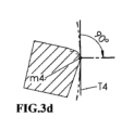
本発明に係る方法は、図3及び図3a~図3eを用いて以下により詳細に説明する。図3は、再び、工具設計に従って精密に形成されている切削歯14を示している。ただし、歯は、角度Σだけ傾斜した方位で示されている。上記歯14の左側刃先28(以下では簡潔に総括して刃先Sとしても示される)において、接触点m1~m5が設けられ、接触点m1~m5において、ワーク加工中、仕上がったワークの歯面に刃先が接触する。接触点m1~m5のそれぞれは、工具とワークとの間の異なる転動角度に対応する。接触点m1~m5は、工具設計から容易に計算することができる。接触点m1~m5は、丸みを帯びている刃先にわたって延在する経路に位置する。上記接触点m1~m5の間の接続は、補償曲線17によって形成される。上記経路は、図2における縁部16から大幅に偏差を有することを見て取ることができる。
The method according to the invention will be explained in more detail below with the aid of FIG. 3 and FIGS. 3a to 3e. FIG. 3 again shows the cutting
本発明に係る方法は、上記偏差を考慮に入れる。工具軸は、各接触点m1~m5に関して、鉛直線に対して異なる角度Σだけ傾斜し、そのため、レーザービーム12又は円筒形検知面T1~T5は、それぞれ、関連する接触点m1~m5において接線方向に刃先に接触する。このために必要な角度Σの値は、工具設計に基づいて容易に計算することもできる。このようにして、接触点の経路に沿った刃先の幾何形状は、測定の結果として精密に求めることができる。この場合、以下が適用される。すなわち、刃先の面法線は、それぞれの接触点m1~m5においてワークの加工された歯面に対して常に垂直であり、それに対応して、レーザービーム又は円筒形検知面T1~T5は、この垂線に対して常に直角である。
The method according to the invention takes into account the above deviations. The tool axis is inclined for each contact point m1-m5 by a different angle Σ with respect to the vertical line, so that the
図3a~図3eは、平面S1~S5における拡大断面において、接触点m1~m5における幾何学的条件の概略図を示している。図3a~図3dでは代表的なものしか示さないが、図3eは、ここで関連する全ての参照符号(接触点m5、アールr5、すくい面18、すくい面の面取り部19、接触点の空間的移動経路24、刃先における垂線32)を示す。接触点m1~m5の位置が湾曲部分において接触点ごとに変化する様子、及びそれに対して接線方向である円筒形検知面T1~T5の方向が、工具軸Bに対して対応して変化する様子を見て取ることができる。丸みを帯びている右側の仮想刃先29が測定される場合、変化した軸位置において更なる測定サイクルが行われる。
Figures 3a to 3e show schematic representations of the geometrical conditions at the contact points m1 to m5 in enlarged sections in planes S1 to S5. Although FIGS. 3a to 3d only show representative ones, FIG. The
図4及び図4aは、仮想工具1vによって加工される仮想ワーク3vを示している。仮想ワーク3vは、仮想工具1vによって仕上げられたワークに対応する。空間における円筒形検知面の位置、ここでは、検知面T3又はレーザービーム12の位置は、再び上記図を用いて説明する。仮想工具1vの工具軸Bは、その測定位置に角度Σ3だけ旋回する。仮想工具1vの右側刃先29は、接触点m3において仮想ワーク3vの湾曲した歯面Czに接触する。曲率は、表面曲線13によって示される。レーザービーム12の検知面T3は、ここでは、接触点m3に関連する接線方向平面Ctにおける湾曲した歯面Czに位置するように延在し、歯面方向、すなわち、ねじれ角の方向(ここでは角度β3によって示されている)に位置合わせされる。
4 and 4a show a
図5、図5a、及び図5bは、5つの接触点m1~m5、関連する5つの測定トラックR1~R5、及び関連する5つの円筒形検知面T1~T5を有する切削歯14の様々な図を示している。図5は、図3と同様の斜視図を示している。図5aは、上記切削歯14の側面図を示している。それぞれZ軸に沿った異なる位置Z1~Z5を有する個々の接触点m1~m5を見て取ることができる。したがって、接触点m1~m5は、Z軸に対して垂直な共通の平面には位置しない。したがって、工具のZ位置は、様々な接触点m1~m5における測定のそれぞれについて修正する必要がある。
5, 5a and 5b show various views of a cutting
図5bは、切削歯14の平面図を示している。切削歯14を有するホブピーリング工具1が、例えば測定トラックR1において円筒形検知面T1を通過して移動する場合、刃先が接触点m1において検知面T1に接触する際の回転角度Φ1は、検出されるレーザーブリッジの0信号によって検出することができる。回転角度Φ2~Φ5は、更なる測定トラックR2~R5についても同様に検出され、円筒形検知面T2~T5は、工具軸Bに対して修正された角度位置をそれぞれ有する。上記回転角度の検出は、刃先Sにおける接触点の精密なイメージを可能にする。
FIG. 5b shows a plan view of the cutting
図6は、再び、図3と同様の切削歯14の斜視図を示しているが、2つの接触点m1及びm5のみが、関連する断面S1及びS5並びに関連する検知面T1及びT5を伴って示されている。検知面は、ここでもレーザービーム12によって実現することができる。図6a~図6dは、平面S1及びS5における切削歯14を通る断面の概略図を示しており、以下の説明が当てはまる。
-図6aは、平面S1において、加工のための軸位置における断面を示し、図6bは、接触点m1を測定するための軸位置における断面を示している。
-図6cは、平面S5において、加工のための軸位置における断面を示し、図6dは、接触点m5を測定するための軸位置における断面を示している。
-測定のための関連する軸位置において、円筒形検知面T1及びT5は、常に、空間的に固定された状態で鉛直に配置される。
FIG. 6 again shows a perspective view of the cutting
- FIG. 6a shows a cross-section in the axial position for machining in the plane S1, and FIG. 6b shows a cross-section in the axial position for measuring the contact point m1.
- FIG. 6c shows a cross-section in the axial position for machining in plane S5, and FIG. 6d shows a cross-section in the axial position for measuring the contact point m5.
- In the relevant axial position for the measurement, the cylindrical sensing surfaces T1 and T5 are always arranged vertically in a spatially fixed manner.
加工のための軸位置から第1の接触点m1を測定するための軸位置に工具を移動させ、工具を円筒形検知面に対して位置合わせするために、利用可能な機械軸が用いられる。このために、工具スピンドル2、及び本発明の実現形態によってはワークスピンドル4も、並進軸X及びYによって測定位置Mpに移動する。工具スピンドル2は、最初は、依然として元の設定角度Σにある。更なる軸Zによって、切削歯14における第1の接触点m1が、水平平面Mxy(図1aを参照)の高さにおいてレーザービーム12の中心に移動する。必要な場合、X軸及びY軸がこのために再び用いられる。軸を測定のために配向する場合、工具スピンドル2を、旋回軸Aによって新たな設定角度Σ1に旋回させ、以前の工具設定角度Σを、接触点m1におけるねじれ角β1によって補正する。その結果、設定は、加工のための軸位置から、選択された接触点における測定のための軸位置へと変換される。工具設定角度Σ1に旋回すると、工具スピンドル2は、規定の回転速度nBで、少なくともスピンドルの完全な1回転を行い、レーザービームが刃先によって遮られる回転角度Φが検出される。1回目の測定の後、工具スピンドル2は、次の接触点m2における測定のための軸位置に移動し、このシーケンスは、接触点m5における測定に至るまで同様に繰り返される。上記測定シーケンスは、逆順で行うこともできる。刃先の片側における接触点を測定した後、刃先の他の側における接触点も同様に測定する。このために、工具スピンドル2の同じ又は修正された回転方向を用いることができる。
The available machine axes are used to move the tool from the axial position for machining to the axial position for measuring the first contact point m1 and to align the tool with the cylindrical sensing surface. For this purpose, the
非接触で作用するレーザービーム12によって、測定時に問題なく60回転/分よりも大きいスピンドル回転速度nBを使用することができる。したがって、少なくとも5つの測定トラックR1~R5による完全な測定が、5秒~10秒未満で実行可能である。通常、5回の測定サイクルの後、十分に測定された値が得られ、CNCコントローラー8において表形式で記憶される。その後、上記値を、必要に応じて、測定技術における通常の方法を用いて評価することができる。必要な場合、測定サイクルの回数を増やすことができる。本例では、レーザービーム12又は検知面T1~T5は、鉛直に配置される。しかしながら、これに代わって、レーザービームは、他の任意の所望の空間的方位を有することもできる。別様に配置されたレーザービーム又は別様に配置された検知面の場合も、加工のための軸位置から、それぞれ測定される接触点に関連する測定のための軸位置への設定の変換が、同様の方法で行われる。
Due to the non-contact acting
図7は、鉛直レーザービーム12を備える測定装置11を示しており、仮想ホブピーリング工具1vの接触点m3が、測定位置Mpに位置している。これに関して、仮想ホブピーリング工具1vは、横断方向断面Bxyにおける実工具1の簡略化された表現として理解することもできる。スピンドル軸B又は横断方向断面Bxyは、事前に説明した工具設定角度Σ3だけ旋回する。測定位置Mpは、平面Mxy、Mxz、及びMyzの固定の交点に位置する。また、仮想ホブピーリング工具1vと転動しながら係合する仮想ワーク3vも示されており、レーザービーム12は、共通の接触点m3において接線方向に歯面Czに接触する。上記仮想ワーク3vは、純粋に視覚的な説明のために示されている。
FIG. 7 shows a measuring
仮想ホブピーリング工具1vは、スピンドル回転速度nBでレーザービーム12を通過して回転し、L信号26及び0信号27が、切削歯14ごとに交互に生成される。切削歯14がレーザービーム12を遮ると、0信号27が生成される。上記レーザービーム12は、歯溝において再び遮蔽が解かれ、L信号26が生成される。CNC工具スピンドルBの対応する角度位置は、L信号26の場合及び0信号27の場合の双方で検出される。例えば、右側刃先29の第1の測定サイクルの場合、0信号27のみが評価され、CNCコントローラー8に表形式で記憶されることに留意すべきである。工具スピンドルBの同じ回転方向を有するが、左側刃先28のための修正された軸位置を有する第2の測定サイクルの場合、L信号のみが評価され、同じく表形式で記憶される。測定値は、CNCコントローラー8において各測定トラックに割り当てられ、可能な最終結果が、図8に概略的に示されている。図7aは、レーザービーム12から離れるように旋回した第1の切削歯14の例として、上記第1の測定により、斜めの位置における第1の切削歯中心15をL/0信号によって規定することができることを更に示している。上記中心15が基準値として用いられる場合、工具スピンドルBの後続の角度位置は、この値を参照することができる。
The virtual
この場合、一つのみの測定トラックR3における各個別の切削歯中心15を求め、ここから平均値を形成すれば十分であり得る。前記平均値が規定の公差範囲Δ内にある場合、加工を安全に開始することができる。同心度Rを測定するのにも、一つのみの測定トラックにおける測定で十分であり得、同心度測定は、切削歯中心の検出と同様に行われる。一方、切削歯14の刃先の形状を検出するには、複数の、好ましくは少なくとも5つの測定トラックR1~R5における測定が必要である。
In this case, it may be sufficient to determine each individual
また、歯形状の工具1vにおけるL/0信号を、線形のL/0信号帯域25として概略的に示すことができる。工具1vには75個の切削歯z1~z75があり、L信号及び0信号も75回生成される。その結果、測定された偏差は、特に制御パネル9のスクリーン上に、視覚的に非常に良好に示すことができる。
Further, the L/0 signal in the tooth-shaped
図7aは、領域D3内の接触点m3における細部の拡大図を示している。刃先28、29、30、及び31は、この図において説明のための一例として示されている。さらに、仮想工具1v、レーザービーム12、切削歯14、斜めの位置の切削歯中心15、L信号26及び0信号27、接触点m3、測定位置Mp、同心度R、測定トラックR3、及びピッチ角度τが示されている。
FIG. 7a shows an enlarged view of the detail at contact point m3 in area D3. Cutting
図8は、各測定トラックR1~R5に対するL/0信号の角度位置Φの概略図を示している。既に言及したように、上記角度位置は、CNCコントローラー8に記憶され、制御パネル9のスクリーン上に表示され、様々な測定タスクに必要に応じて使用することができる。曲線当てはめの標準的な数学プロセスによって、最小二乗法を用いて比較的簡単かつ迅速な方法で、例えば、同心度R、切削歯中心15、及び/又はピッチ角度τを求めることが可能である。三次元の刃先Sをスキャンするためには、複数の、好ましくは少なくとも5つの測定トラックR1~R5を通る。また、補償曲線17を有する刃先Sの幾何形状は、最小二乗法を用いて測定された値から求めることができる。その後、事前に計算された理想的な刃先21との比較が可能になる。測定結果をチェックするために、更なる測定トラックを非常に迅速に通ることができる。既定の公差範囲(公差マージンΔ)が点線で示されている。
FIG. 8 shows a schematic diagram of the angular position Φ of the L/0 signal for each measurement track R1-R5. As already mentioned, said angular positions are stored in the
図9、図9a、図10、及び図10aは、レーザーブリッジ11を必ずしも鉛直に位置合わせする必要がないことを示している。上述したようなレーザーブリッジは、図9及び図9aにおいて、レーザービーム12が鉛直に、Z軸に対して平行に延びるように位置合わせされる。レーザービーム12が精密に円筒形であるか又はレーザービーム12の測定中に有効となる領域が精密に円筒形状である場合、ワーク1のZ軸に沿った精密な位置は、この配置の場合、重要でない。したがって、Z方向における精密な位置決めは必要ない。特に、工具1は、測定のために必ずしも図1aにおける基準平面Mxyに位置する必要がない。対照的に、図10及び図10aでは、レーザーブリッジ11は、Y軸の周りに角度δで鉛直から外れて傾斜する。結果として、レーザーブリッジ11と工具スピンドル2の工具ホルダー又は工具シャンクとの間の衝突のリスクが低減される。しかしながら、レーザービーム12は、ここではZ軸に対して平行に延びない。その結果、工具スピンドル2は、Z方向に関する測定中、測定される接触点が、仮想刃先における基準平面Mxyに精密に位置するように位置決めする必要がある。したがって、レーザービーム12のこの位置合わせでは、Z方向に沿った工具の精密な位置決めが必要になる。
Figures 9, 9a, 10 and 10a show that the
図11は、その代替として、触覚検知装置23によって測定されるホブピーリング工具1vを示している。切削歯14は、スキャンされることが好ましい。接触式の測定のため、測定中にホブピーリング工具1vが自由に回転することは可能でない。スキャン動作の場合、CNC軸A、B、及びXが同時に比較的ゆっくりと動く。Z軸は、必ずしも動かす必要はない。必要な場合、Y軸も同期させて伴うことができる。実際には、対応する測定曲線21を、少なくとも3つの切削歯14において測定することができる。検知装置23は、この場合、円筒形検知面T1とともに円筒形の検知フィンガーも用いる。
FIG. 11 shows, as an alternative, a
図11aは、図11の領域D4における、触覚検知装置23の円筒形検知面T1と、スキャンされる切削歯14との間の係合を示している。上記スキャンの過程で、触覚検知装置23の円筒形検知面T1も、ホブピーリング工具1vの丸みを帯びている刃先Sに接線方向に当接する。しかしながら、工具軸Bの周りの関連する角度位置Φに関するスキャンされた測定値21が、L/0信号の代わりに生成される。
FIG. 11a shows the engagement between the cylindrical sensing surface T1 of the
図12及び図13は、従来の歯車切削機械のプラットフォーム上に設置されるホブピーリング機械におけるレーザーブリッジ11の可能な配置を示している。
12 and 13 show a possible arrangement of the
図12は、レーザーブリッジ11の形態の測定装置がワークキャリア33の形態の可動キャリア上に配置される、ホブピーリング機械の一変形形態を示している。ワークキャリア33は、鉛直軸C*の周りで複数の位置に旋回可能である。そのような可動ワークキャリアを備える機械の構想は、米国特許第6,565,418号に開示されている。ワークスピンドル4も、レーザーブリッジ11に対して旋回方向に関してオフセットされて(本例では90度オフセットされて)、ワークキャリア33上に配置される。上記ワークキャリア33が軸C*の周りに旋回する結果、ワークスピンドル4又はレーザーブリッジ11のいずれかが、工具1と相互作用する位置に移動することができる。ワークキャリアは、第1のワークスピンドルに対して180度だけオフセットされて配置された第2のワークスピンドル(図面には示されていない)を支持することができる。図12における図では、上記第2のワークスピンドルは、上記ワークキャリアの後側に位置する。このようにして、ワークスピンドルのうちの一つにおいて加工を行うことができ、一方、仕上がったワークは、他のワークスピンドル上の新たに加工されるワークと交換することができる。その結果、生産を行わない遊休時間が回避される。上記機械構想では、工具スピンドル2は、工具キャリア34上に配置された可動なホブピーリングヘッド35に収容され、工具キャリア34は、機械ベッド6上に変位可能に位置する。
FIG. 12 shows a variant of the hob peeling machine in which a measuring device in the form of a
図12aは、図12の領域D5における拡大された細部を示している。前記細部から見て取ることができるように、本例におけるレーザーブリッジ11のレーザービーム12は、鉛直に位置合わせされず、鉛直に対して傾斜角度δをとることが好ましい。これは、レーザーブリッジ11が、ワークキャリア33の外形内に依然として存在することを可能にし、その結果、作業空間のシールをより容易にする。
FIG. 12a shows an enlarged detail in area D5 of FIG. As can be seen from the above details, the
ホブピーリング機械の別の変形形態が図13に示されている。前記ホブピーリング機械は、米国特許第5,857,894号に開示されているような機械構想に基づく。上記実施形態では、レーザーブリッジ11は、機械ベッド6上に固定的に配置され、測定に必要な動きは、変位可能かつ旋回可能な工具キャリア34によって実行される。上記機械構想における工具スピンドル2は、機械ベッド6上に位置する上記工具キャリア34上に配置された可動ホブピーリングヘッド35内に収容される。工具キャリア34は、図示されていない加工位置と、図13に示されている測定位置との間で鉛直軸C*の周りに旋回可能である。加工位置において、工具1は、上記ワークを加工するために、ワーク3と相互作用することが可能であるように配置される。対照的に、測定位置では、工具1は、レーザーブリッジ11の形態の測定装置と相互作用することが可能であるように配置される。本例では、加工位置と測定位置との間の旋回角度は、180度である。しかしながら、他の旋回角度も想定可能であることは明らかである。
Another variant of the hob peeling machine is shown in FIG. The hob peeling machine is based on a machine concept as disclosed in US Pat. No. 5,857,894. In the embodiment described above, the
図13aは、図13の領域D6における拡大された細部を示している。前記細部から見て取ることができるように、レーザーブリッジ11のレーザービーム12は、鉛直に位置合わせされず、本例でも鉛直に対して角度δをとる。しかしながら、レーザーブリッジ11の鉛直の固定配置も想定可能である。
Figure 13a shows an enlarged detail in area D6 of Figure 13. As can be seen from the above details, the
硬質加工のための歯車切削機械22における自動化された工具測定は、測定位置Mpにおける工具1と測定装置との記載された動作対の間の非常に精密な相対移動を必要とする。他の動作対の工具1とワーク3との間の利用可能な相対移動は、通常、マイクロメートル範囲内、又は回転軸の場合、角度秒の範囲内の高レベルの基本的な幾何学的精度を既に有する。ホブピーリング機械22の作業空間内における信頼性のある非常に精密な測定を確実にするために、測定位置Mpは、各加工の開始時に自動的に、また必要に応じて随時較正すべきである。このために可能な手順は、図14、図14a、及び図14bを用いて以下に説明される。
Automated tool measurement in a
図14は、軸X、Y、及びZの座標系を有する図示されていないホブピーリング機械22における較正マンドレル36を示している。規定の高さh(図14aを参照)及び規定の較正直径φD(図14bを参照)を有する較正マンドレル36が、図示されていない工具スピンドル2に収納され、位置Z1*における較正平面EKに移動する。レーザーブリッジ11の測定位置Mpも、上記平面に位置する。したがって、較正マンドレル36が、図14aにおける好適なX位置からまず開始して、測定位置Mpの方向においてY軸とともに移動すると、較正マンドレル36は、較正直径φDによってレーザービーム12に交差し、上記レーザービームはかき消される。この場合、CNCコントローラー8においてY位置Y1*.0をマークする0信号27が、レーザーブリッジ11において生成される。Y軸が更に移動すると、較正直径φDは、再びレーザービーム12の遮蔽を解き、0信号27と同様に、CNCコントローラー8においてY位置Y1*.LをマークするL信号26が生成される。CNCコントローラー8によって、双方のY位置間の中心は、レーザービーム12とワーク軸Cとの間の距離ymを規定するものとみなされる。しかしながら、これは、測定点Mpの高度に精密な較正にはまだ十分ではない。平面Y-Zにおけるレーザービーム12の精密な角度むき方位εも検出又は設定しなければならない。本発明の枠組み内で、ホブピーリング工具1の測定は、任意の所望の角度方位εにおいて行うことができ、当然ながら、好ましい方法では鉛直方位が用いられる。したがって、より高いZ位置Z2*における第2の較正工程が有意であり、Y位置Y2*.0及びY2*.Lが、同様にマーク及び評価される。より高い精度要件の場合、更なるZ位置においても較正工程を行うことができる。CNCコントローラー8は、上記値を用いて高度に精密に角度方位εを求めることが可能である。レーザービーム12が、Y方向に沿った上記較正の場合に較正直径φDに交差しない場合、X方向に沿った位置を調整しなければならない。
FIG. 14 shows a
較正中の次の工程は、図14bに示されている距離xm及び角度位置δを求めるために、X方向に沿って行われる。レーザービーム12の工具軸Cまでのym距離が先行の較正工程において求められていることから、Y軸が工具スピンドル2を伴って回転対称の較正マンドレル36を上記位置に移動させることができる。開始時、上記工具スピンドル2は、X軸のゼロ位置及び較正平面EKのZ1*位置にある。その後、工具スピンドル2は、較正マンドレル36を、較正直径φDがレーザービーム12に交差し、上記の記載にしたがってCNCコントローラー8においてX位置X1*.0をマークする0信号27を生成し、その結果、レーザービームのワーク軸Cからのxm距離を規定するまでX方向に前進させる。平面X-Zにおける傾斜設定角度δは、レベルZ2*における同様の較正動作を用いて求めることができる。
The next step during the calibration is performed along the X direction to determine the distance xm and angular position δ shown in Figure 14b. Since the ym distance of the
それにより、各較正動作後、較正された距離ym及びxm並びに測定位置Mpに対する関連する角度位置δ及びεは、CNCコントローラー8に保存され、更なる測定のために用いることができる。
Thereby, after each calibration operation, the calibrated distances ym and xm and the associated angular positions δ and ε for the measurement position Mp are stored in the
一方で、上記較正動作の記載は、較正平面EKにおけるホブピーリング工具1の好ましい測定が、角度誤差とはほとんど無関係となり、その結果、精密に円筒形のレーザービーム12とともに有利に用いることが可能になることも示している。
On the one hand, the above description of the calibration operation shows that the preferred measurement of the
図15は、工具スピンドル2上に好ましい方法で配置することができるスキャン式検知装置10を用いた、ピーリングされたワーク3における任意のポストプロセス測定を示している。前記測定は、例えば、少なくとも3つの歯溝において、従来の基礎円測定に従って行われる。必要な場合、測定結果を用いて、ワーク加工のための設定の更なる補正を行う。このようにして、最適な品質保証を達成することができる。
FIG. 15 shows an optional post-process measurement on a peeled
工具は、本図面の全てにおいて非常に概略的に示されている。加えて、全ての切削歯のすくい面は、上記図面における工具の場合、共通の平面に位置している。しかしながら、上記所見は、図示の工具に限定されず、任意の所望のホブピーリング工具、更には段差カット若しくは他の幾何学的設計を有する工具、又は他の歯車形状の工具に用いることができる。 The tool is shown very schematically in all of the figures. In addition, the rake faces of all cutting teeth lie in a common plane for the tool in the above figures. However, the above observations are not limited to the illustrated tool, but can be used with any desired hob peeling tool, as well as tools with step cuts or other geometric designs, or other gear-shaped tools.
概して、本明細書において提案される方法は、以下の利点を可能にする。
-開始時及びワークの加工中、レーザーブリッジ11により、非接触の迅速かつ高精度のプロセス内測定が行われ、全ての測定値は、コントローラーに記憶される。
-現在の測定値と開始値とを連続的に比較することにより、刃先に対する寸法の変化、例えば摩耗V(図6bを参照)を検出することができる。
-三次元の丸みを帯びている刃先Sを補償曲線17により直接検出し、それにより、エンベロープカットによるホブピーリング中、ピーリングされたワーク3における最終的な歯面が形成され、ひいてはまた画定される。
-作用する刃先の精密な測定によって、一連のワークの加工時、ホブピーリング機械のCNC軸に対する好適な設定を、時間を掛けて探すことを明らかに低減することができ、プロセス関連の不適合が大幅に回避される。
In general, the method proposed herein enables the following advantages.
- At the start and during the machining of the workpiece, non-contact, fast and highly accurate in-process measurements are carried out by the
- By continuously comparing the current measured value with the starting value, it is possible to detect dimensional changes to the cutting edge, for example wear V (see FIG. 6b).
- direct detection of the three-dimensional rounded cutting edge S by means of the
- Precise measurement of the working cutting edge clearly reduces the time-consuming search for suitable settings for the CNC axis of the hob peeling machine when machining a series of workpieces, significantly reducing process-related non-conformities. be avoided.
要約すると、本明細書において提案される方法は、以下の特徴を有する。
-丸みを帯びている刃先に接線方向に当接する円筒形検知面を測定に用いることができる。
-円筒形検知面が、それぞれの接触点においてワークの湾曲した歯面上の関連する接平面にあり、この場合、好ましくは対応するねじれ角の方向に位置合わせされるように配置される。
-精密に円形で、円筒形の、高度に精密なレーザービームが、円筒形検知面として用いられることが好ましい。円筒形検知インサートを備える触覚測定検知装置を、本発明の他の実施形態に対する一例として用いることもできる。一方で、これに関連して、長い測定時間、触覚スキャン、及び複雑な信号処理は不都合である。
-したがって、測定レーザービームは、ワークの湾曲した歯面における対応する接触点の接平面にあり、測定中、他の接触点において関連するねじれ角に旋回する必要がある。歯面における上記点ごとのねじれ角は、歯の高さが増加するにつれてサイズが拡大する。レーザービームの方位、ひいてはまた対応する測定装置の設定は、上記ねじれ角及び工具設定角度によって確定される。レーザービームには、総じておよそ0度~90度の調整可能な角度領域を必須とすべきである。
-しかしながら、実際には、レーザービームを備える測定装置が上記動作を実行する必要がある場合、コストに関してかなり不都合がある。したがって、レーザービームは、有利な方法では、ホブピーリング機械の作業空間において本質的に固定され、鉛直に配置することができ、レーザービームと工具軸との間の位置合わせの設定は、代わりに、工具スピンドルの既存のCNC旋回装置によって実現される。それに応じて、既存のCNC軸X、Y、及びZによって線形送りも実現することができる。機械設定は、このために、測定位置に対応して計算される。加えて、本質的に固定された測定位置を、ワーク位置から間隔を置いて配置し、それにより、工具を伴う工具スピンドルの位置決めのために衝突をなくすのに十分な空間が存在することが有利である。
-また、固定的に配置されたレーザービームによって、複数の、好ましくは少なくとも5つの径方向測定トラックを、それぞれ、工具設定角度の固定設定値で通りながら、回転するホブピーリング工具における歯形状の丸みを帯びている刃先領域において、規定の回転速度でスキャンすることが可能である。歯面ごとのそれぞれの計算された接触点は、軸X、Y、Z、A、及びBにおける線形送り及び回転送りによって、レーザービームに対する測定位置に位置決めされる。歯形状の工具を回転させる際にレーザービームを交互に遮ることによって、非常に簡単な方法で、信頼性のあるシンプルなL/0信号を生成することができる。刃先の片側が測定されると、刃先の他の側を、同様の方法で、修正された設定を用いて測定することができる。
-工具の切削歯が測定トラックにおいてレーザービームを通過して移動すると、L/0信号によってシンプルに接触点を検出することができ、回転するCNC工具スピンドルの対応する角度値を検出することができる。上記角度値及び径方向測定トラックの設定は、CNCコントローラーにおいて表形式で記憶することができ、歯車に典型的な様々な測定に用いることができる。
In summary, the method proposed herein has the following features.
- A cylindrical sensing surface tangentially abutting a rounded cutting edge can be used for measurements.
- a cylindrical sensing surface is located in the relevant tangential plane on the curved tooth flank of the workpiece at each point of contact, in this case preferably arranged such that it is aligned in the direction of the corresponding helix angle;
- A precisely circular, cylindrical, highly precise laser beam is preferably used as the cylindrical sensing surface. A tactile measurement sensing device with a cylindrical sensing insert may also be used as an example for other embodiments of the invention. On the one hand, long measurement times, tactile scanning and complex signal processing are disadvantageous in this connection.
- The measuring laser beam is therefore in the tangential plane of the corresponding contact point on the curved tooth flank of the workpiece and has to be swiveled to the relevant torsion angle at the other contact point during the measurement. The point-to-point helix angle on the tooth surface increases in size as the tooth height increases. The orientation of the laser beam and thus also the corresponding setting of the measuring device is determined by the helix angle and the tool setting angle. The laser beam should generally have an adjustable angular range of about 0 degrees to 90 degrees.
- However, in practice there are considerable disadvantages in terms of costs if a measuring device with a laser beam is required to perform the above operations. Therefore, the laser beam can advantageously be arranged essentially fixed and vertically in the working space of the hob peeling machine, and the setting of the alignment between the laser beam and the tool axis can instead be This is realized by the existing CNC swivel of the tool spindle. Correspondingly, a linear feed can also be realized with the existing CNC axes X, Y and Z. Machine settings are calculated for this purpose corresponding to the measurement position. In addition, it is advantageous to arrange the essentially fixed measuring position at a distance from the workpiece position, so that for the positioning of the tool spindle with the tool there is sufficient space to eliminate collisions. It is.
- Also, the rounding of the tooth profile in a rotating hob peeling tool is determined by means of a fixedly arranged laser beam, passing through a plurality, preferably at least five radial measuring tracks, each with a fixed setting of the tool setting angle. It is possible to scan at a specified rotational speed in the region of the cutting edge that has a Each calculated contact point for each tooth flank is positioned at the measurement position relative to the laser beam by linear and rotary feeds in the axes X, Y, Z, A, and B. By alternately interrupting the laser beam as the tooth-shaped tool rotates, a reliable and simple L/0 signal can be generated in a very simple way. Once one side of the cutting edge is measured, the other side of the cutting edge can be measured in a similar manner and with modified settings.
- When the cutting tooth of the tool moves past the laser beam in the measuring track, the point of contact can be detected simply by means of the L/0 signal and the corresponding angle value of the rotating CNC tool spindle can be detected. . The above angle values and radial measurement track settings can be stored in tabular form in the CNC controller and used for various measurements typical of gears.
本明細書において提案される方法は、円筒形検知面(例えば、レーザービームの形態)が接線方向に刃先をスキャンする例を用いて上記で説明した。この場合、重要な態様は、各場合に、仮想刃先における仮想接触点が計算され、刃先における仮想接触点の位置に応じた刃先と測定装置との間の方位及び並進位置において測定が実現されることであった。この場合、上記に挙げた利点の少なくとも一部は、円筒形状でない検知面を用いて達成することもできる。例えば、接触点に収束するレーザービームを用いることが想定可能である。例えば、ボールの形態の非円筒形の物理的検知手段を用いることも想定可能である。 The method proposed herein has been explained above using an example in which a cylindrical sensing surface (eg in the form of a laser beam) scans the cutting edge tangentially. In this case, an important aspect is that in each case a virtual contact point at the virtual cutting edge is calculated and a measurement is realized in the azimuthal and translational position between the cutting edge and the measuring device depending on the position of the virtual contact point on the cutting edge. Was that. In this case, at least some of the advantages listed above can also be achieved using a sensing surface that is not cylindrical. For example, it is conceivable to use a laser beam that focuses on the point of contact. It is also conceivable to use non-cylindrical physical sensing means, for example in the form of a ball.
挙げられた利点の少なくとも一部は、接線方向スキャンの実行だけでなく、別様に測定される刃先によって、例えば、三角法又は3Dスキャン測定を用いた距離測定によって更に達成することもできる。これに関して、上記に提示した方法は、円筒形検知面による接線方向スキャンに限定されない。 At least some of the mentioned advantages can be achieved not only by performing a tangential scan, but also by a differently measured cutting edge, for example by distance measurement using trigonometry or 3D scan measurements. In this regard, the method presented above is not limited to tangential scanning with a cylindrical sensing surface.
1 ホブピーリング工具
1v 仮想ホブピーリング工具
2 工具スピンドル
3 ワーク、歯車
3v 仮想ワーク
4 ワークスピンドル
5 送りキャリッジ
6 機械ベッド
7 歯合わせプローブ
8 CNCコントローラー
9 制御パネル
10 スキャン式検知装置
11 レーザーブリッジ
12 レーザービーム
13 表面曲線
14 切削歯
15 切削歯中心
16 刃先アールの逃げ面への移行部における縁部
17 補償曲線
18 すくい面
19 すくい面の面取り部
20 ホブピーリング機械の作業空間
21 スキャンされた測定曲線、測定値
22 ホブピーリング機械、歯車製造機械
23 触覚検知装置
24 接触点の移動経路
25 L/0信号帯域
26 L信号
27 0信号
28 刃先、左側
29 刃先、右側
30 歯元の刃先
31 歯先の刃先
32 刃先における垂線
33 ワークキャリア
34 工具キャリア
35 ホブピーリングヘッド
36 較正マンドレル
37 刃先ブランク
A 工具スピンドルの旋回軸
B 工具軸
Bxy 横断方向断面における工具の基準平面
C ワーク軸
Ct 工具とワークとの接触点における接平面
Cz ワークにおける歯面
C* 工具キャリアの旋回軸
C** ワークキャリアの旋回軸
D1~D6 図における細部の領域
φD 較正マンドレルにおける較正直径
EK 位置Z1*における較正平面
h 較正マンドレルにおける高さ
K ワーク軸CにおけるX及びYの原点を有する機械の座標系
Mp 測定位置
Mxz X方向におけるレーザービームの中心を通る鉛直平面
Myz Y方向におけるレーザービームの中心を通る鉛直平面
Mxy レーザーブリッジの水平中心平面
m1~m5 刃先における仮想接触点
nB 工具スピンドルの回転速度
R ホブピーリング工具の同心度
R1~R5 ホブピーリング工具における測定トラックのアール
r1~r5 刃先のアール
S 仮想刃先
S1~S5 切削歯におけるすくい面に対して垂直かつ補償曲線に対して直角の断面
T1~T5 丸みを帯びている刃先に接線方向に当接する円筒形検知面
V 刃先における摩耗
X 並進CNC軸
X1*.0 較正平面EKにおける較正時のX位置
X2*.0 Z位置Z2*における較正時のX位置
xm レーザービームとワーク軸との間のX距離
Y 並進CNC軸
Y1*.0 レーザーブリッジにおける0信号を用いた較正平面EKにおける較正時のY位置
Y1*.L レーザーブリッジにおけるL信号を用いた較正平面EKにおける較正時のY位置
Y2*.0 レーザーブリッジにおける0信号を用いたZ位置Z2*における較正時のY位置
Y2*.L レーザーブリッジにおけるL信号を用いたZ位置Z2*における較正時のY位置
ym レーザービームとワーク軸との間のY距離
Z 並進CNC軸
Z1* 較正平面EKにおける較正時のZ位置
Z2* 較正時の増加したZ位置
Z1~Z5 切削歯中心15に対する工具における接触点のZ高さ
z1~z75 工具の歯の数、例えばz75
β ピッチ円(基準円)におけるねじれ角
β1~β5 様々な歯高におけるワーク歯面のねじれ角
δ X方向におけるワークスピンドルの回転軸に対するレーザービームの傾斜角度
ε Y方向におけるワークスピンドルの回転軸に対するレーザービームの角度位置
Δ 公差範囲
Σ 加工のための軸位置における工具角度
Σ1~Σ5 測定のための軸位置における工具角度
τ ピッチ角度
Φ1~Φ5 CNC工具スピンドルの角度位置
1 Hob peeling tool 1v Virtual hob peeling tool 2 Tool spindle 3 Work, gear 3v Virtual work 4 Work spindle 5 Feed carriage 6 Machine bed 7 Alignment probe 8 CNC controller 9 Control panel 10 Scan type detection device 11 Laser bridge 12 Laser beam 13 Surface curve 14 Cutting tooth 15 Cutting tooth center 16 Edge at the transition of the cutting edge radius to the flank surface 17 Compensation curve 18 Rake face 19 Chamfer of the rake face 20 Working space of the hob peeling machine 21 Scanned measurement curve, measured values 22 Hob peeling machine, gear manufacturing machine 23 Tactile sensing device 24 Movement path of contact point 25 L/0 signal band 26 L signal 27 0 signal 28 Cutting edge, left side 29 Cutting edge, right side 30 Root cutting edge 31 Cutting edge of tooth tip 32 Cutting edge 33 Workpiece carrier 34 Tool carrier 35 Hob peeling head 36 Calibration mandrel 37 Cutting edge blank A Pivoting axis of the tool spindle B Tool axis Bxy Reference plane of the tool in transverse section C Workpiece axis Ct Tangent plane at the point of contact between tool and workpiece Cz Tooth flank on the workpiece C * Pivoting axis of the tool carrier C ** Pivoting axis of the workpiece carrier D1 to D6 Area of detail in the diagram φD Calibration diameter on the calibration mandrel EK Calibration plane at position Z1 * h Height on the calibration mandrel K Workpiece axis Machine coordinate system with X and Y origins at C Mp Measurement position Mxz Vertical plane passing through the center of the laser beam in the X direction Myz Vertical plane passing through the center of the laser beam in the Y direction Mxy Horizontal central plane of the laser bridge m1 to m5 Virtual contact point on the cutting edge nB Rotation speed of the tool spindle R Concentricity of the hob peeling tool R1 to R5 Radius of the measuring track on the hob peeling tool r1 to r5 Radius of the cutting edge S Virtual cutting edge S1 to S5 Perpendicular to the rake face on the cutting tooth and a cross section perpendicular to the compensation curve T1-T5 Cylindrical sensing surface tangentially abutting the rounded cutting edge V Wear on the cutting edge X Translational CNC axis X1 * . 0 X position at the time of calibration on the calibration plane EK X2 * . 0 X position during calibration at Z position Z2 * xm X distance between laser beam and workpiece axis Y Translational CNC axis Y1 * . 0 Y position during calibration in the calibration plane EK with 0 signal in the laser bridge Y1 * . L Y position during calibration in the calibration plane EK using the L signal in the laser bridge Y2 * . 0 Y position Y2 * during calibration at Z position Z2 * with 0 signal in the laser bridge. L Z position using the L signal in the laser bridge Z2 * Y position during calibration ym Y distance between laser beam and workpiece axis Z Translational CNC axis Z1 * Z position during calibration in calibration plane EK Z2 * During calibration Increased Z position of Z1-Z5 Z-height of the point of contact on the tool with respect to the cutting
β Torsion angle in the pitch circle (reference circle) β1 to β5 Torsion angle of the workpiece tooth surface at various tooth heights δ Inclination angle of the laser beam with respect to the rotational axis of the workpiece spindle in the X direction ε Laser with respect to the rotational axis of the workpiece spindle in the Y direction Angular position of the beam Δ Tolerance range Σ Tool angle in the axial position for machining Σ1 to Σ5 Tool angle in the axial position for measurement τ Pitch angle Φ1 to Φ5 Angular position of the CNC tool spindle
Claims (22)
前記実工具(1)は、工具軸(B)の周りに回転可能であるとともに、各々が実刃先を形成する複数の切削歯(14)を有し、前記方法は、測定装置(11;23)を用いて実行され、
前記方法は、
(a)仮想工具(1v)の仮想刃先(S)であって、刃先の長手方向に沿って延在するとともに、前記刃先の長手方向に対して横方向に丸みを帯びている当該仮想刃先(S)に対して、仮想接触点(m1~m5)を計算する工程であって、前記仮想刃先(S)は、予め定められた前記実刃先の所望の刃先形状に対応しており、前記仮想接触点(m1~m5)の計算は、前記仮想刃先(S)が、前記仮想工具(1v)が仮想ワーク(3v)と転動運動を行う際に、前記仮想接触点(m1~m5)で前記仮想ワーク(3v)と接触するように実行し、前記仮想ワーク(3v)は、予め定義された所望の歯面形状を有し、前記転動運動は、前記実工具(1)による前記実ワーク(3)の実際の加工の場合と同じである工程と、
(b)前記測定装置(11;23)が、仮想接触点(m1~m5)において測定が実施できるように、前記計算された仮想接触点(m1~m5)に基づいて、前記工具軸(B)と前記測定装置(11;23)との間の相対方位(Σ1~Σ5)と、前記実工具(1)と前記測定装置(11;23)との間の並進相対位置とを計算する工程と、
(c)前記工具軸(B)と前記測定装置(11;23)との間の前記計算された相対方位と、前記実工具(1)と前記測定装置(11;23)との間の前記計算された並進相対位置とを設定する工程と、
(d)前記設定された相対方位及び並進相対位置において、前記実工具(1)の少なくとも一の前記切削歯(14)の前記実刃先に対して測定を実行する工程と、
を含むことを特徴とする、方法。 A method of measuring an actual tool (1) for generating machining of an actual workpiece (3) that becomes a toothed workpiece, the method comprising:
The actual tool (1) is rotatable around a tool axis (B) and has a plurality of cutting teeth (14) each forming an actual cutting edge, and the method includes a measuring device (11; 23). ) is executed using
The method includes:
(a) A virtual cutting edge (S) of the virtual tool (1v), which extends along the longitudinal direction of the cutting edge and is rounded in the transverse direction with respect to the longitudinal direction of the cutting edge ( S), the virtual cutting edge (S) corresponds to a desired cutting edge shape of the real cutting edge determined in advance, and the virtual cutting edge (S) corresponds to a desired cutting edge shape of the actual cutting edge , and Calculation of the contact points (m1 to m5) is performed when the virtual cutting edge (S) performs rolling motion with the virtual tool (1v) and the virtual workpiece (3v). The virtual workpiece (3v) has a predefined desired tooth surface shape, and the rolling motion is caused by the real tool (1) to contact the virtual workpiece (3v). A process that is the same as in the actual processing of the actual workpiece (3);
(b) The measuring device (11; 23) uses the tool axis (B ) and the measuring device (11; 23), and calculating the relative orientation (Σ1 to Σ5) between the actual tool (1) and the measuring device (11; 23), and the relative translational position between the actual tool (1) and the measuring device (11; 23). and,
(c) the calculated relative orientation between the tool axis (B) and the measuring device (11; 23) and the calculated relative orientation between the actual tool (1) and the measuring device (11; 23); and setting the calculated translational relative position.
(d) performing a measurement on the actual cutting edge of at least one of the cutting teeth (14) of the actual tool (1) at the set relative orientation and translational relative position;
A method, comprising:
前記仮想刃先(S)によって作製される仮想歯面に対する、前記実刃先によって作製される歯面の外形の偏差に関する少なくとも一つの尺度、
前記創成加工中の前記実刃先の変化に関する少なくとも一つの尺度、
のうちの少なくとも一つを、前記複数の仮想接触点(m1~m5)のために前記実刃先について求められた、前記工程(d)の測定結果から求める、請求項2又は3に記載の方法。 The following parameters, i.e.
at least one measure regarding the deviation of the external shape of the tooth flank produced by the real cutting edge with respect to the virtual tooth flank produced by the virtual cutting edge (S);
at least one measure regarding a change in the actual cutting edge during the generating process;
The method according to claim 2 or 3, wherein at least one of the plurality of virtual contact points (m1 to m5) is determined from the measurement results of the step ( d) determined on the actual cutting edge. .
以下のパラメーター、すなわち、
前記実工具(1)の同心度、
切削歯中心、
歯溝中心、
のうちの少なくとも一つを、前記測定から求める、請求項1~4のいずれか1項に記載の方法。 said measurement is performed on a plurality of cutting teeth (14) in step (d);
The following parameters, i.e.
Concentricity of the actual tool (1) ,
Cutting tooth center,
tooth groove center,
The method according to any one of claims 1 to 4, wherein at least one of the following is determined from the measurement.
前記相対方位(Σ1~Σ5)及び前記並進相対位置の前記設定は、空間内での前記工具軸(B)の方位及び空間内での前記実工具(1)の並進位置を修正することによってなされる、請求項1~5のいずれか1項に記載の方法。 the measuring device (11) is arranged spatially fixed during the execution of the method;
The setting of the relative orientation (Σ1 to Σ5) and the relative translational position is performed by correcting the orientation of the tool axis (B) in space and the translational position of the actual tool (1) in space. The method according to any one of claims 1 to 5.
前記検知手段は、円筒軸、円筒半径、及び前記円筒軸から前記円筒半径に対応する距離を置いて延在する円筒形検知面を画定し、前記相対方位(Σ1~Σ5)及び前記並進相対位置は、前記円筒軸が、前記仮想接触点における前記仮想刃先(S)上の接平面に対して平行に延在するとともに、前記円筒軸が、前記接平面から前記円筒半径に対応する距離を置くように、計算され、設定される、請求項7に記載の方法。 The detection means has a cylindrical shape,
The sensing means defines a cylindrical axis, a cylindrical radius, and a cylindrical sensing surface extending from the cylindrical axis at a distance corresponding to the cylindrical radius, and the sensing means defines the relative orientation (Σ1 to Σ5) and the translational relative position. The cylindrical axis extends parallel to a tangential plane on the virtual cutting edge (S) at the virtual contact point, and the cylindrical axis is spaced from the tangential plane at a distance corresponding to the cylindrical radius. 8. The method according to claim 7, wherein the method is calculated and set as follows.
前記実工具(1)は、工程(d)における測定を実行するために、前記工具軸(B)の周りに回転し、
前記光ビームが前記実刃先によって遮られる際の実回転角度が、その回転中に検出される、請求項7~9のいずれか1項に記載の方法。 said sensing means are formed by a light beam (12);
The actual tool (1) rotates around the tool axis (B) in order to perform the measurement in step (d),
Method according to any one of claims 7 to 9, wherein the actual rotation angle at which the light beam is interrupted by the real cutting edge is detected during its rotation.
(e)前記測定の結果によって、機械コントローラー(8)の少なくとも一つの設定を求める工程と、
(f)前記機械コントローラー(8)に前記設定を送信する工程と、
を更に含み、
前記設定により、前記実ワーク(3)と前記実工具(1)との間の相対位置が、前記実ワーク(3)の加工のために設定される、請求項1~14のいずれか1項に記載の方法。 The method includes at least the following steps:
(e) determining at least one setting of the machine controller (8) according to the result of said measurement;
(f) transmitting the settings to the machine controller (8);
further including;
Any one of claims 1 to 14, wherein the setting sets a relative position between the actual workpiece (3) and the actual tool (1) for machining the actual workpiece (3). The method described in.
ホブピーリング工具、又は、
歯車成形工具、
のうちの一つである、請求項1~15のいずれか1項に記載の方法。 The actual tool (1) is the following tool:
hob peeling tool, or
gear forming tools,
16. The method according to any one of claims 1 to 15.
前記実工具(1)は、各々が実刃先を形成する複数の切削歯(14)を有し、
前記装置は、
前記実工具(1)を工具軸(B)の周りに回転するように駆動する工具スピンドル(2)と、
測定装置(11)と、
前記工具軸(B)と前記測定装置(11)との間の相対方位(Σ)を修正するための少なくとも一つの駆動旋回軸(A)と、
前記実工具(1)と前記測定装置(11)との間の並進相対位置を修正するための少なくとも一つの駆動線形軸(X、Y、Z)と、
を備え、
前記装置は、前記駆動旋回軸(A)及び前記少なくとも一つの駆動線形軸(X、Y、Z)を用いて、前記請求項1~17のいずれか1項に記載の方法を実行するように構成されたコントローラー(8)を備えることを特徴とする、装置。 An apparatus for carrying out a method for measuring a tool (1) for generating machining of an actual workpiece (3) that becomes a toothed workpiece, the apparatus comprising:
The real tool (1) has a plurality of cutting teeth (14) each forming a real cutting edge,
The device includes:
a tool spindle (2) that drives the actual tool (1) to rotate around a tool axis (B);
a measuring device (11);
at least one drive pivot axis (A) for correcting the relative orientation (Σ) between the tool axis (B) and the measuring device (11);
at least one driving linear axis (X, Y, Z) for correcting the relative translational position between the actual tool (1) and the measuring device (11);
Equipped with
The device is adapted to carry out the method according to any one of the preceding claims using the drive pivot axis (A) and the at least one drive linear axis (X, Y, Z). Device, characterized in that it comprises a configured controller (8).
前記駆動旋回軸(A)は、前記測定装置(11)に対する空間内の前記工具軸(B)の前記相対方位を修正するように構成され、
前記少なくとも一つの駆動線形軸(X、Y、Z)は、前記測定装置(11)に対する空間内の前記実工具(1)の前記並進相対位置を修正するように構成されている、請求項18に記載の装置。 The measuring device (11) is arranged to remain stationary during the measurement,
the drive pivot axis (A) is configured to modify the relative orientation of the tool axis (B) in space with respect to the measuring device (11);
18. The at least one drive linear axis (X, Y, Z) is configured to modify the translational relative position of the real tool (1) in space with respect to the measuring device (11). The device described in.
前記測定装置(11)は、前記可動キャリア(33)上に配置され、
前記測定装置(11)は、前記可動キャリア(33)によって停止位置から測定位置に可動である、請求項18又は19に記載の装置。 The apparatus comprises a machine bed (6) and a movable carrier (33), the movable carrier (33) being movable between a plurality of positions relative to the machine bed (6);
The measuring device (11) is arranged on the movable carrier (33),
20. Apparatus according to claim 18 or 19, wherein the measuring device (11) is movable from a rest position to a measuring position by means of the movable carrier (33).
前記コントローラーは、算出された仮想接触点(m1~m5)で前記検知手段が仮想刃先(S)に接触するように、前記相対方位(Σ1~Σ5)及び前記並進相対位置を算出及び設定し、
前記コントローラーは、前記工具軸(B)の前記設定された相対方位(Σ1~Σ5)及び前記設定された相対座標における前記測定中に、前記工具スピンドル(2)が前記実工具(1)を前記工具軸(B)の周りに回転させるように、前記工具スピンドル(2)に相互作用し、
前記光検出器は、前記光ビーム(12)が回転中に前記刃先によって遮られる際の実回転角度を検出するように構成されている、請求項18~21のいずれか1項に記載の装置。 The measuring device (11) comprises a light source and a photodetector, the light source being configured to generate a light beam (12) directed towards the photodetector , and the sensing means configured to generate a light beam (12) directed towards the photodetector. ) formed by at least one region of
The controller calculates and sets the relative orientation (Σ1 to Σ5) and the translational relative position so that the detection means contacts the virtual cutting edge (S) at the calculated virtual contact points (m1 to m5),
The controller is configured to cause the tool spindle (2) to move the actual tool (1) during the measurement at the set relative orientation (Σ1 to Σ5) of the tool axis (B) and the set relative coordinates. interacting with said tool spindle (2) to cause it to rotate about a tool axis (B);
Apparatus according to any one of claims 18 to 21, wherein the photodetector is configured to detect the actual rotation angle at which the light beam (12) is interrupted by the cutting edge during rotation. .
Applications Claiming Priority (3)
| Application Number | Priority Date | Filing Date | Title |
|---|---|---|---|
| CH01526/17 | 2017-12-15 | ||
| CH01526/17A CH714443B1 (en) | 2017-12-15 | 2017-12-15 | Method and device for measuring a rolling machining tool. |
| PCT/EP2018/083747 WO2019115332A1 (en) | 2017-12-15 | 2018-12-06 | Method and device for measuring a roll machining tool |
Publications (2)
| Publication Number | Publication Date |
|---|---|
| JP2021506598A JP2021506598A (en) | 2021-02-22 |
| JP7356977B2 true JP7356977B2 (en) | 2023-10-05 |
Family
ID=60813558
Family Applications (1)
| Application Number | Title | Priority Date | Filing Date |
|---|---|---|---|
| JP2020531739A Active JP7356977B2 (en) | 2017-12-15 | 2018-12-06 | Method and device for measuring creative machining tools |
Country Status (8)
| Country | Link |
|---|---|
| US (1) | US11850671B2 (en) |
| EP (1) | EP3724598B1 (en) |
| JP (1) | JP7356977B2 (en) |
| KR (1) | KR102559309B1 (en) |
| CN (1) | CN111492199B (en) |
| CH (1) | CH714443B1 (en) |
| ES (1) | ES2907004T3 (en) |
| WO (1) | WO2019115332A1 (en) |
Families Citing this family (8)
| Publication number | Priority date | Publication date | Assignee | Title |
|---|---|---|---|---|
| DE102018122759A1 (en) * | 2018-09-17 | 2020-03-19 | Chiron-Werke Gmbh & Co. Kg | Method and device for wear analysis on a machine tool |
| CH715794B8 (en) | 2019-07-17 | 2020-11-13 | Reishauer Ag | Machine tool for rolling machining of rotating parts with groove-shaped profiles. |
| DE102021102122B4 (en) * | 2021-01-29 | 2023-12-28 | Klingelnberg GmbH. | Method and device for measuring a toothing |
| CN113108724A (en) * | 2021-05-31 | 2021-07-13 | 大连工业大学 | Full-automatic cutter coaxiality detection device based on laser sensor |
| CN113485246B (en) * | 2021-07-08 | 2022-12-20 | 浙江科雄电子科技有限公司 | Machine tool dynamic cutting simulation system and method based on Unity3D |
| CN115365979B (en) * | 2022-10-25 | 2023-01-24 | 中国科学院长春光学精密机械与物理研究所 | Optical processing tool calibration method, device, computer equipment and readable storage medium |
| CN115755770B (en) * | 2023-01-03 | 2024-07-26 | 天津大学 | A method for identifying position-independent geometric errors of dual rotating axes based on distance error |
| CN119328592A (en) * | 2024-12-13 | 2025-01-21 | 内蒙古一机集团瑞特精密工模具有限公司 | A grinding method for a tooth-cutting tool with an involute-like curved rake face |
Citations (10)
| Publication number | Priority date | Publication date | Assignee | Title |
|---|---|---|---|---|
| DE19927872A1 (en) | 1999-04-01 | 2000-10-26 | Werth Messtechnik Gmbh | Device for measuring object or its structure, especially one with protrusions, e.g. teeth of milling tool, has optical sensor and radiation source operating from movable pivoting device |
| JP2001138135A (en) | 1999-10-12 | 2001-05-22 | Gleason Corp | Device for grinding gear or gear type tool |
| JP2002532265A (en) | 1998-12-14 | 2002-10-02 | ライシャウァー アーゲー | Method and apparatus for machining toothed workpieces such as gears before machining |
| WO2009036886A1 (en) | 2007-09-14 | 2009-03-26 | Carl Mahr Holding Gmbh | Method and device for tool measurement |
| WO2012079734A1 (en) | 2010-12-16 | 2012-06-21 | E. Zoller Gmbh & Co. Kg | Setting and/or measurement apparatus |
| JP2013505843A (en) | 2009-09-24 | 2013-02-21 | グリーソン カッティング ツールズ コーポレイション | Tool grinding machine |
| JP2013124889A (en) | 2011-12-14 | 2013-06-24 | Tohoku Univ | Contour shape measuring method and contour shape measuring device |
| JP2014039971A (en) | 2012-08-21 | 2014-03-06 | Aisin Seiki Co Ltd | Cutter for skiving |
| JP2014237185A (en) | 2013-06-07 | 2014-12-18 | 株式会社ジェイテクト | Gear processing simulation apparatus |
| JP2017087400A (en) | 2015-11-17 | 2017-05-25 | ローランドディー.ジー.株式会社 | Correction method and correction apparatus |
Family Cites Families (23)
| Publication number | Priority date | Publication date | Assignee | Title |
|---|---|---|---|---|
| US5255199A (en) | 1990-12-14 | 1993-10-19 | Martin Marietta Energy Systems, Inc. | Cutting tool form compensaton system and method |
| JPH04232407A (en) * | 1990-12-28 | 1992-08-20 | Seikosha Co Ltd | Inspecting method of tool |
| JPH0655341A (en) * | 1992-08-13 | 1994-03-01 | Kashifuji:Kk | Gear and tool measuring method in nc gear cutting machine |
| KR970001041B1 (en) * | 1994-06-23 | 1997-01-25 | 한국수자원공사 | Process for the preparation of light weight aggregate material |
| DE19625370C1 (en) | 1996-06-25 | 1997-04-30 | Reishauer Ag | Grinding machine for continuous roller grinding of spur wheel gears |
| US6496273B1 (en) | 1999-05-05 | 2002-12-17 | Renishaw Plc | Position determining apparatus for coordinate positioning machine |
| EP1398598A1 (en) | 2002-09-16 | 2004-03-17 | WENDT GmbH | Method and device to measure small cutting edge geometries |
| ITBO20030536A1 (en) | 2003-09-16 | 2005-03-17 | Marposs Spa | METHOD AND SYSTEM TO CHECK THE POSITION OF A MECHANICAL PART |
| KR100612834B1 (en) * | 2003-11-15 | 2006-08-18 | 삼성전자주식회사 | 3D position measuring sensor |
| DE102008035667B4 (en) * | 2008-07-31 | 2010-06-17 | Siemens Aktiengesellschaft | gearmotor |
| DE102009036776B4 (en) | 2009-08-08 | 2014-11-27 | Niles Werkzeugmaschinen Gmbh | Method for measuring the allowance of a hard-to-machine gear |
| CN101782374A (en) * | 2010-03-16 | 2010-07-21 | 西安交通大学 | Gear and moulding structure outline measuring method based on template near-field light projection scanning |
| EP2570217B1 (en) * | 2011-09-15 | 2014-11-05 | Klingelnberg AG | Semi-completing skiving method and device with skiving tool for performing a semi-completing skiving method |
| DE102012011956B3 (en) * | 2012-06-17 | 2013-12-12 | Herbert Schriefer | Hob peeling tool for use in rolling peeling machine for hob peeling gearing, has cutting elements including sharpening area protruding from tool receiver, where area is located between maximum and minimum radial distances of edges |
| SE1350983A1 (en) * | 2013-08-27 | 2015-02-28 | Sandvik Intellectual Property | Tools and cutters for shell milling |
| DE102013015239A1 (en) * | 2013-09-13 | 2015-03-19 | Liebherr-Verzahntechnik Gmbh | Process for setting up a gear cutting machine and gear cutting machine |
| DE102013015253A1 (en) | 2013-09-13 | 2015-03-19 | Gleason-Pfauter Maschinenfabrik Gmbh | Measuring geometry, measuring device with such a measuring geometry and measuring method |
| CH709478A1 (en) * | 2014-04-08 | 2015-10-15 | Reishauer Ag | Methods and apparatus for fast and flexible dressing of the grinding worm. |
| CN103994717B (en) * | 2014-05-24 | 2017-04-19 | 长春市春求科技开发有限公司 | Optical gear measurement device and detection method |
| JP5955429B1 (en) | 2015-03-06 | 2016-07-20 | トヨタ自動車北海道株式会社 | Continuously generating gear grinding method |
| DE102015104310A1 (en) | 2015-03-23 | 2016-09-29 | Profilator Gmbh & Co. Kg | Method and device for toothing a work wheel with reduced flank line error |
| DE102017120570A1 (en) | 2017-09-07 | 2019-03-07 | Liebherr-Verzahntechnik Gmbh | Device for processing a workpiece with a tool |
| DE102017120788A1 (en) | 2017-09-08 | 2019-03-14 | Liebherr-Verzahntechnik Gmbh | Method and device for skiving |
-
2017
- 2017-12-15 CH CH01526/17A patent/CH714443B1/en not_active IP Right Cessation
-
2018
- 2018-12-06 JP JP2020531739A patent/JP7356977B2/en active Active
- 2018-12-06 US US16/766,329 patent/US11850671B2/en active Active
- 2018-12-06 EP EP18815646.7A patent/EP3724598B1/en active Active
- 2018-12-06 KR KR1020207020571A patent/KR102559309B1/en active Active
- 2018-12-06 CN CN201880080956.3A patent/CN111492199B/en active Active
- 2018-12-06 ES ES18815646T patent/ES2907004T3/en active Active
- 2018-12-06 WO PCT/EP2018/083747 patent/WO2019115332A1/en unknown
Patent Citations (10)
| Publication number | Priority date | Publication date | Assignee | Title |
|---|---|---|---|---|
| JP2002532265A (en) | 1998-12-14 | 2002-10-02 | ライシャウァー アーゲー | Method and apparatus for machining toothed workpieces such as gears before machining |
| DE19927872A1 (en) | 1999-04-01 | 2000-10-26 | Werth Messtechnik Gmbh | Device for measuring object or its structure, especially one with protrusions, e.g. teeth of milling tool, has optical sensor and radiation source operating from movable pivoting device |
| JP2001138135A (en) | 1999-10-12 | 2001-05-22 | Gleason Corp | Device for grinding gear or gear type tool |
| WO2009036886A1 (en) | 2007-09-14 | 2009-03-26 | Carl Mahr Holding Gmbh | Method and device for tool measurement |
| JP2013505843A (en) | 2009-09-24 | 2013-02-21 | グリーソン カッティング ツールズ コーポレイション | Tool grinding machine |
| WO2012079734A1 (en) | 2010-12-16 | 2012-06-21 | E. Zoller Gmbh & Co. Kg | Setting and/or measurement apparatus |
| JP2013124889A (en) | 2011-12-14 | 2013-06-24 | Tohoku Univ | Contour shape measuring method and contour shape measuring device |
| JP2014039971A (en) | 2012-08-21 | 2014-03-06 | Aisin Seiki Co Ltd | Cutter for skiving |
| JP2014237185A (en) | 2013-06-07 | 2014-12-18 | 株式会社ジェイテクト | Gear processing simulation apparatus |
| JP2017087400A (en) | 2015-11-17 | 2017-05-25 | ローランドディー.ジー.株式会社 | Correction method and correction apparatus |
Also Published As
| Publication number | Publication date |
|---|---|
| JP2021506598A (en) | 2021-02-22 |
| CN111492199A (en) | 2020-08-04 |
| ES2907004T3 (en) | 2022-04-21 |
| CN111492199B (en) | 2022-05-10 |
| CH714443A1 (en) | 2019-06-28 |
| KR102559309B1 (en) | 2023-07-24 |
| EP3724598B1 (en) | 2022-01-19 |
| EP3724598A1 (en) | 2020-10-21 |
| CH714443A8 (en) | 2019-09-13 |
| WO2019115332A1 (en) | 2019-06-20 |
| CH714443B1 (en) | 2020-10-15 |
| KR20200096832A (en) | 2020-08-13 |
| US11850671B2 (en) | 2023-12-26 |
| US20200368835A1 (en) | 2020-11-26 |
Similar Documents
| Publication | Publication Date | Title |
|---|---|---|
| JP7356977B2 (en) | Method and device for measuring creative machining tools | |
| CN109465502B (en) | Method and apparatus for shaving teeth | |
| CN110355426B (en) | Device for chamfering toothed workpieces | |
| JP6955296B2 (en) | Cutting equipment and contact position identification program | |
| KR101544449B1 (en) | Tool grinding machine | |
| US10239139B2 (en) | Method for machining a set of teeth, tool arrangement, and tooth-cutting machine | |
| JP7195277B2 (en) | Measurement of characteristic parameters of finishing tools | |
| US7179025B2 (en) | Machine and method with 7 axes for CNC-controlled machining, particularly generating cutting or grinding; of spiral bevel gears | |
| JP2010225141A (en) | Method and device for generating converted control data for controlling tool by machine tool | |
| JPH11511393A (en) | Method and apparatus for reshaping a cutter head | |
| JP2003191131A (en) | Method for machining essentially cylindrical internal gear or external gear | |
| JP2008272861A (en) | Tool position measuring method, tool position measuring system, and machining method | |
| US20230046784A1 (en) | Method for working a workpiece with two toothings, positioning device for determining a reference rotational angle position of the workpiece and power tool with such a positioning device | |
| JP4510755B2 (en) | Tool edge position calculation method and machine tool | |
| JP2005046997A (en) | Method and cutting machine for cutting spiral bevel gear | |
| JP7317030B2 (en) | How to prepare and run a machining process, its control software, chamfering station and gear machine with chamfering station | |
| JP2022542982A (en) | Method for hard finishing two teeth of a workpiece, tooth cutting machine, control program, hard finishing combination tool, and sensor arrangement therefor | |
| JP7074381B2 (en) | Cutting equipment | |
| US20230113347A1 (en) | Tap phase detection method, female thread processing method in machine tool, and machine tool | |
| JP7303593B2 (en) | POSITIONAL RELATIONSHIP MEASUREMENT METHOD AND PROCESSING DEVICE | |
| JP2005098752A (en) | Broach shape measuring device | |
| JP7456191B2 (en) | Gear processing equipment and gear processing method | |
| JP3898437B2 (en) | Grooving method and processing apparatus used directly for the implementation | |
| JP2024010304A (en) | Skiving processing device |
Legal Events
| Date | Code | Title | Description |
|---|---|---|---|
| A621 | Written request for application examination |
Free format text: JAPANESE INTERMEDIATE CODE: A621 Effective date: 20210913 |
|
| A977 | Report on retrieval |
Free format text: JAPANESE INTERMEDIATE CODE: A971007 Effective date: 20220824 |
|
| A131 | Notification of reasons for refusal |
Free format text: JAPANESE INTERMEDIATE CODE: A131 Effective date: 20220830 |
|
| A601 | Written request for extension of time |
Free format text: JAPANESE INTERMEDIATE CODE: A601 Effective date: 20221130 |
|
| A521 | Request for written amendment filed |
Free format text: JAPANESE INTERMEDIATE CODE: A523 Effective date: 20230110 |
|
| A131 | Notification of reasons for refusal |
Free format text: JAPANESE INTERMEDIATE CODE: A131 Effective date: 20230328 |
|
| A521 | Request for written amendment filed |
Free format text: JAPANESE INTERMEDIATE CODE: A523 Effective date: 20230523 |
|
| A131 | Notification of reasons for refusal |
Free format text: JAPANESE INTERMEDIATE CODE: A131 Effective date: 20230815 |
|
| A521 | Request for written amendment filed |
Free format text: JAPANESE INTERMEDIATE CODE: A523 Effective date: 20230815 |
|
| TRDD | Decision of grant or rejection written | ||
| A01 | Written decision to grant a patent or to grant a registration (utility model) |
Free format text: JAPANESE INTERMEDIATE CODE: A01 Effective date: 20230829 |
|
| A61 | First payment of annual fees (during grant procedure) |
Free format text: JAPANESE INTERMEDIATE CODE: A61 Effective date: 20230925 |
|
| R150 | Certificate of patent or registration of utility model |
Ref document number: 7356977 Country of ref document: JP Free format text: JAPANESE INTERMEDIATE CODE: R150 |