JP7304576B2 - NOISE REDUCTION DEVICE, MOBILE DEVICE, AND NOISE REDUCTION METHOD - Google Patents
NOISE REDUCTION DEVICE, MOBILE DEVICE, AND NOISE REDUCTION METHOD Download PDFInfo
- Publication number
- JP7304576B2 JP7304576B2 JP2019207026A JP2019207026A JP7304576B2 JP 7304576 B2 JP7304576 B2 JP 7304576B2 JP 2019207026 A JP2019207026 A JP 2019207026A JP 2019207026 A JP2019207026 A JP 2019207026A JP 7304576 B2 JP7304576 B2 JP 7304576B2
- Authority
- JP
- Japan
- Prior art keywords
- signal
- noise reduction
- control unit
- noise
- reduction device
- Prior art date
- Legal status (The legal status is an assumption and is not a legal conclusion. Google has not performed a legal analysis and makes no representation as to the accuracy of the status listed.)
- Active
Links
- 230000009467 reduction Effects 0.000 title claims description 128
- 238000000034 method Methods 0.000 title claims description 56
- VJYFKVYYMZPMAB-UHFFFAOYSA-N ethoprophos Chemical compound CCCSP(=O)(OCC)SCCC VJYFKVYYMZPMAB-UHFFFAOYSA-N 0.000 title 1
- 238000012545 processing Methods 0.000 claims description 86
- 238000012546 transfer Methods 0.000 claims description 79
- 230000003044 adaptive effect Effects 0.000 claims description 46
- 238000012937 correction Methods 0.000 claims description 43
- 230000008569 process Effects 0.000 claims description 23
- 230000008859 change Effects 0.000 claims description 17
- 230000000875 corresponding effect Effects 0.000 claims description 14
- 230000002596 correlated effect Effects 0.000 claims description 5
- 238000005562 fading Methods 0.000 claims description 2
- 238000010586 diagram Methods 0.000 description 28
- 238000001514 detection method Methods 0.000 description 24
- 230000000694 effects Effects 0.000 description 8
- 230000002159 abnormal effect Effects 0.000 description 7
- 230000007274 generation of a signal involved in cell-cell signaling Effects 0.000 description 7
- 101150003973 ADF4 gene Proteins 0.000 description 4
- 239000000470 constituent Substances 0.000 description 4
- 230000001276 controlling effect Effects 0.000 description 4
- 238000004422 calculation algorithm Methods 0.000 description 3
- 230000007246 mechanism Effects 0.000 description 3
- 101150082901 ADF3 gene Proteins 0.000 description 2
- 230000002238 attenuated effect Effects 0.000 description 2
- 238000004364 calculation method Methods 0.000 description 2
- 238000004590 computer program Methods 0.000 description 2
- 230000007423 decrease Effects 0.000 description 2
- 239000002184 metal Substances 0.000 description 2
- 229910052751 metal Inorganic materials 0.000 description 2
- 238000005070 sampling Methods 0.000 description 2
- 239000004065 semiconductor Substances 0.000 description 2
- 230000002123 temporal effect Effects 0.000 description 2
- 101150086503 ADF1 gene Proteins 0.000 description 1
- 101150024356 ADF2 gene Proteins 0.000 description 1
- 101100384717 Schizosaccharomyces pombe (strain 972 / ATCC 24843) cof1 gene Proteins 0.000 description 1
- 230000005540 biological transmission Effects 0.000 description 1
- 230000030279 gene silencing Effects 0.000 description 1
- 239000000463 material Substances 0.000 description 1
- 239000011159 matrix material Substances 0.000 description 1
- 238000012986 modification Methods 0.000 description 1
- 230000004048 modification Effects 0.000 description 1
- 230000004044 response Effects 0.000 description 1
- 230000003584 silencer Effects 0.000 description 1
- 230000001743 silencing effect Effects 0.000 description 1
- 230000000087 stabilizing effect Effects 0.000 description 1
Images


Classifications
-
- H—ELECTRICITY
- H04—ELECTRIC COMMUNICATION TECHNIQUE
- H04R—LOUDSPEAKERS, MICROPHONES, GRAMOPHONE PICK-UPS OR LIKE ACOUSTIC ELECTROMECHANICAL TRANSDUCERS; DEAF-AID SETS; PUBLIC ADDRESS SYSTEMS
- H04R3/00—Circuits for transducers, loudspeakers or microphones
- H04R3/02—Circuits for transducers, loudspeakers or microphones for preventing acoustic reaction, i.e. acoustic oscillatory feedback
-
- H—ELECTRICITY
- H04—ELECTRIC COMMUNICATION TECHNIQUE
- H04R—LOUDSPEAKERS, MICROPHONES, GRAMOPHONE PICK-UPS OR LIKE ACOUSTIC ELECTROMECHANICAL TRANSDUCERS; DEAF-AID SETS; PUBLIC ADDRESS SYSTEMS
- H04R1/00—Details of transducers, loudspeakers or microphones
- H04R1/02—Casings; Cabinets ; Supports therefor; Mountings therein
- H04R1/025—Arrangements for fixing loudspeaker transducers, e.g. in a box, furniture
-
- H—ELECTRICITY
- H04—ELECTRIC COMMUNICATION TECHNIQUE
- H04R—LOUDSPEAKERS, MICROPHONES, GRAMOPHONE PICK-UPS OR LIKE ACOUSTIC ELECTROMECHANICAL TRANSDUCERS; DEAF-AID SETS; PUBLIC ADDRESS SYSTEMS
- H04R1/00—Details of transducers, loudspeakers or microphones
- H04R1/02—Casings; Cabinets ; Supports therefor; Mountings therein
- H04R1/028—Casings; Cabinets ; Supports therefor; Mountings therein associated with devices performing functions other than acoustics, e.g. electric candles
-
- H—ELECTRICITY
- H04—ELECTRIC COMMUNICATION TECHNIQUE
- H04R—LOUDSPEAKERS, MICROPHONES, GRAMOPHONE PICK-UPS OR LIKE ACOUSTIC ELECTROMECHANICAL TRANSDUCERS; DEAF-AID SETS; PUBLIC ADDRESS SYSTEMS
- H04R29/00—Monitoring arrangements; Testing arrangements
- H04R29/001—Monitoring arrangements; Testing arrangements for loudspeakers
- H04R29/002—Loudspeaker arrays
-
- H—ELECTRICITY
- H04—ELECTRIC COMMUNICATION TECHNIQUE
- H04R—LOUDSPEAKERS, MICROPHONES, GRAMOPHONE PICK-UPS OR LIKE ACOUSTIC ELECTROMECHANICAL TRANSDUCERS; DEAF-AID SETS; PUBLIC ADDRESS SYSTEMS
- H04R3/00—Circuits for transducers, loudspeakers or microphones
- H04R3/12—Circuits for transducers, loudspeakers or microphones for distributing signals to two or more loudspeakers
-
- H—ELECTRICITY
- H04—ELECTRIC COMMUNICATION TECHNIQUE
- H04R—LOUDSPEAKERS, MICROPHONES, GRAMOPHONE PICK-UPS OR LIKE ACOUSTIC ELECTROMECHANICAL TRANSDUCERS; DEAF-AID SETS; PUBLIC ADDRESS SYSTEMS
- H04R2227/00—Details of public address [PA] systems covered by H04R27/00 but not provided for in any of its subgroups
- H04R2227/001—Adaptation of signal processing in PA systems in dependence of presence of noise
-
- H—ELECTRICITY
- H04—ELECTRIC COMMUNICATION TECHNIQUE
- H04R—LOUDSPEAKERS, MICROPHONES, GRAMOPHONE PICK-UPS OR LIKE ACOUSTIC ELECTROMECHANICAL TRANSDUCERS; DEAF-AID SETS; PUBLIC ADDRESS SYSTEMS
- H04R2410/00—Microphones
- H04R2410/05—Noise reduction with a separate noise microphone
-
- H—ELECTRICITY
- H04—ELECTRIC COMMUNICATION TECHNIQUE
- H04R—LOUDSPEAKERS, MICROPHONES, GRAMOPHONE PICK-UPS OR LIKE ACOUSTIC ELECTROMECHANICAL TRANSDUCERS; DEAF-AID SETS; PUBLIC ADDRESS SYSTEMS
- H04R2499/00—Aspects covered by H04R or H04S not otherwise provided for in their subgroups
- H04R2499/10—General applications
- H04R2499/11—Transducers incorporated or for use in hand-held devices, e.g. mobile phones, PDA's, camera's
-
- H—ELECTRICITY
- H04—ELECTRIC COMMUNICATION TECHNIQUE
- H04R—LOUDSPEAKERS, MICROPHONES, GRAMOPHONE PICK-UPS OR LIKE ACOUSTIC ELECTROMECHANICAL TRANSDUCERS; DEAF-AID SETS; PUBLIC ADDRESS SYSTEMS
- H04R2499/00—Aspects covered by H04R or H04S not otherwise provided for in their subgroups
- H04R2499/10—General applications
- H04R2499/13—Acoustic transducers and sound field adaptation in vehicles
Landscapes
- Physics & Mathematics (AREA)
- Engineering & Computer Science (AREA)
- Acoustics & Sound (AREA)
- Signal Processing (AREA)
- Health & Medical Sciences (AREA)
- General Health & Medical Sciences (AREA)
- Otolaryngology (AREA)
- Soundproofing, Sound Blocking, And Sound Damping (AREA)
- Fittings On The Vehicle Exterior For Carrying Loads, And Devices For Holding Or Mounting Articles (AREA)
Description
本発明は、騒音を能動的に低減する騒音低減装置等に関する。 The present invention relates to a noise reduction device or the like that actively reduces noise.
従来、スピーカから騒音を打ち消すための音を出力することにより、受聴位置における騒音を能動的に低減する騒音低減装置が知られている。このような騒音低減装置として、例えば、特許文献1には、能動型消音装置が開示されている。
2. Description of the Related Art Conventionally, a noise reduction device is known that actively reduces noise at a listening position by outputting sound for canceling noise from a speaker. As such a noise reduction device, for example,
騒音低減装置においては、スピーカの位置からマイクロフォンの位置までの伝達特性を考慮してキャンセル音を出力するためのキャンセル信号が生成される。そうすると、スピーカ及びマイクロフォンの位置関係に変化が生じるなどの要因で伝達特性が変化した場合には、騒音制御が不安定となり異音などの現象が生じる場合がある。 In the noise reduction device, a cancellation signal for outputting a cancellation sound is generated in consideration of transfer characteristics from the position of the speaker to the position of the microphone. Then, when the transfer characteristics change due to factors such as a change in the positional relationship between the speaker and the microphone, the noise control becomes unstable and abnormal sounds may occur.
本発明は、空間における伝達特性に変化が生じた場合に、当該空間における騒音制御が不安定になることを抑制することができる騒音低減装置、移動体装置、及び、騒音低減方法を提供する。 The present invention provides a noise reduction device, a mobile device, and a noise reduction method capable of suppressing unstable noise control in a space when there is a change in transfer characteristics in the space.
本発明の一態様に係る騒音低減装置は、移動体装置の内部の空間における騒音を低減する騒音低減装置であって、前記騒音と相関を有する参照信号が入力される参照信号入力部と、入力された前記参照信号に基づいて特定される周波数を有する基準信号に逐次更新される係数を有する適応フィルタを適用する処理を行うことにより、前記騒音を低減するためのキャンセル音の出力に用いられるキャンセル信号を生成する適応フィルタ部と、生成された前記キャンセル信号を前記空間に設けられたスピーカに出力するためのキャンセル信号出力部と、前記移動体装置に設けられた可動部の状態を示す状態信号が入力される状態信号入力部と、入力された前記状態信号により前記可動部が所定の基準状態でないことが示される場合に、当該状態信号に前記可動部の移動量を示す情報が含まれるか否かに応じて、前記キャンセル音の出力に関する互いに異なる制御を行う制御部とを備える。 A noise reduction device according to an aspect of the present invention is a noise reduction device that reduces noise in a space inside a mobile device, comprising: a reference signal input unit to which a reference signal correlated with the noise is input; Cancellation used for outputting a cancellation sound for reducing the noise by performing a process of applying an adaptive filter having a coefficient that is sequentially updated to a reference signal having a frequency specified based on the reference signal that has been obtained an adaptive filter section for generating a signal; a cancellation signal output section for outputting the generated cancellation signal to a speaker provided in the space; and a state signal indicating a state of a movable section provided in the mobile device. and whether the state signal includes information indicating the amount of movement of the movable portion when the input state signal indicates that the movable portion is not in a predetermined reference state. and a control unit that performs different controls regarding the output of the canceling sound depending on whether or not the canceling sound is output.
本発明の一態様に係る移動体装置は、前記騒音低減装置と、前記スピーカとを備える。 A mobile device according to an aspect of the present invention includes the noise reduction device and the speaker.
本発明の一態様に係る騒音低減方法は、移動体装置の内部の空間における騒音を低減する騒音低減方法であって、前記騒音と相関を有する参照信号に基づいて特定される周波数を有する基準信号に逐次更新される係数を有する適応フィルタを適用する処理を行うことにより、前記騒音を低減するためのキャンセル音の出力に用いられるキャンセル信号を生成し、生成された前記キャンセル信号を前記空間に設けられたスピーカに出力し、前記移動体装置に設けられた可動部の状態を示す状態信号により前記可動部が所定の基準状態でないことが示される場合に、当該状態信号に前記可動部の移動量を示す情報が含まれるか否かに応じて、前記キャンセル音の出力に関する互いに異なる制御を行う。 A noise reduction method according to an aspect of the present invention is a noise reduction method for reducing noise in a space inside a mobile device, the reference signal having a frequency specified based on a reference signal correlated with the noise. A cancellation signal used to output a cancellation sound for reducing the noise is generated by applying an adaptive filter having coefficients that are successively updated to the space, and the generated cancellation signal is provided in the space. When the state signal indicating the state of the movable portion provided in the mobile device indicates that the movable portion is not in a predetermined reference state, the movement amount of the movable portion is output to the state signal. Different control regarding the output of the canceling sound is performed depending on whether or not the information indicating is included.
本発明の騒音低減装置等、移動体装置、及び、騒音低減方法によれば、空間における伝達特性に変化が生じた場合に、当該空間における騒音制御が不安定になることを抑制することができる。 According to the noise reduction device and the like, the mobile device, and the noise reduction method of the present invention, it is possible to prevent the noise control in the space from becoming unstable when the transfer characteristics in the space change. .
以下、実施の形態について、図面を参照しながら具体的に説明する。なお、以下で説明する実施の形態は、いずれも包括的または具体的な例を示すものである。以下の実施の形態で示される数値、形状、材料、構成要素、構成要素の配置位置及び接続形態、ステップ、ステップの順序などは、一例であり、本発明を限定する主旨ではない。また、以下の実施の形態における構成要素のうち、最上位概念を示す独立請求項に記載されていない構成要素については、任意の構成要素として説明される。 Hereinafter, embodiments will be specifically described with reference to the drawings. It should be noted that the embodiments described below are all comprehensive or specific examples. Numerical values, shapes, materials, components, arrangement positions and connection forms of components, steps, order of steps, and the like shown in the following embodiments are examples and are not intended to limit the present invention. In addition, among the constituent elements in the following embodiments, constituent elements that are not described in independent claims representing the highest concept will be described as arbitrary constituent elements.
また、各図は、模式図であり、必ずしも厳密に図示されたものではない。なお、各図において、実質的に同一の構成に対しては同一の符号を付しており、重複する説明は省略または簡略化される場合がある。 Each figure is a schematic diagram and is not necessarily strictly illustrated. In addition, in each figure, the same code|symbol is attached|subjected with respect to substantially the same structure, and the overlapping description may be abbreviate|omitted or simplified.
(実施の形態1)
[概要]
まず、実施の形態1に係る騒音低減装置の概要について説明する。まず、図1は、実施の形態1に係る騒音低減装置の概要を示す図である。
(Embodiment 1)
[overview]
First, an overview of the noise reduction device according to
図1に示される騒音低減装置10は、例えば、車室内に設置され、自動車の走行中に発生する騒音を低減する装置である。エンジン51に起因する騒音は、瞬間的には単一周波数の正弦波に近い音である。そこで、騒音低減装置10は、エンジン51を制御するエンジン制御部52からエンジン51の周波数を示すパルス信号を取得し、スピーカSPから騒音を打ち消すためのキャンセル音を出力する。キャンセル音の生成には、適応フィルタが用いられ、受聴者30の近傍に配置されたマイクロフォンMによって取得される残留音が小さくなるようにキャンセル音が生成される。
A
図1に示されるように、スピーカSPの位置(以下、出音位置とも記載される)からマイクロフォンMの位置(以下、集音位置とも記載される)までの伝達特性はc1、キャンセル音を出力するための出力信号はoutの記号で表現される。この場合、マイクロフォンMの位置(集音位置)に到達するキャンセル音はc1*outと表現される。なお、「*」は、畳み込み演算子を意味し、c1は伝達特性のインパルス応答を表し、C1は周波数領域での模擬伝達特性を表す。 As shown in FIG. 1, the transfer characteristic from the position of the speaker SP (hereinafter also referred to as the sound output position) to the position of the microphone M (hereinafter also referred to as the sound collection position) is c 1 , and the cancel sound is The output signal for output is represented by the symbol out. In this case, the canceled sound reaching the position of the microphone M (sound collection position) is expressed as c 1 *out. Note that "*" means a convolution operator, c1 represents the impulse response of the transfer characteristic, and C1 represents the simulated transfer characteristic in the frequency domain.
マイクロフォンMの位置における騒音Nmは、振幅をR、角周波数をω、位相をθとすると、下記の(式1)で表現され、c1*outは、下記の(式2-1)、(式2-2)で表される。騒音低減装置10は、(式2-1)、(式2-2)における第1のフィルタ係数A及び第2のフィルタ係数Bを、例えば、LMS(Least Mean Square)法によって算出することで、騒音を打ち消すためのキャンセル音を出力することができる。
The noise N m at the position of the microphone M is expressed by the following (Equation 1), where R is the amplitude, ω is the angular frequency, and θ is the phase. Represented by (Formula 2-2). The

このように、騒音Nmと逆位相のキャンセル音が出力されることにより、図2に示されるように、マイクロフォンMの位置において聞こえる騒音は小さくなっていく。図2は、マイクロフォンMの位置において聞こえる騒音の時間波形を示す模式図である。 As shown in FIG. 2, the noise heard at the position of the microphone M is reduced by outputting the canceling sound having the opposite phase to the noise Nm . FIG. 2 is a schematic diagram showing a temporal waveform of noise heard at the position of the microphone M. As shown in FIG.
[騒音低減装置を備える車両の全体構成]
以下、このような騒音低減装置10の詳細について説明する。実施の形態では、騒音低減装置10は、一例として車両に搭載される。図3は、騒音低減装置10を備える車両の模式図である。
[Overall Configuration of Vehicle Equipped with Noise Reduction Device]
Details of such a
車両50は、移動体装置の一例であって、騒音低減装置10と、エンジン51と、エンジン制御部52と、スピーカSP0~SP4と、マイクロフォンM0~M3と、座席ST0~ST3と、座席状態検出部54と、車両本体55と、ドアDR0~DR4と、ドア状態検出部53とを備える。車両50は、具体的には、自動車であるが、特に限定されない。
A
エンジン51は、車両50の動力源であって、かつ、空間56の騒音源となる駆動装置である。エンジン51は、例えば、空間56とは別の空間内に配置される。エンジン51は、具体的には、車両本体55のボンネット内に形成された空間に設置される。
The
エンジン制御部52は、車両50の運転手のアクセル操作等に基づいて、エンジン51を制御(駆動)する。また、エンジン制御部52は、エンジン51の回転数(周波数)に応じたパルス信号(エンジンパルス信号)を騒音参照信号として出力する。パルス信号の周波数は、例えば、エンジン51の回転数(周波数)に比例する。パルス信号は、具体的には、TDC(Top Dead Center)センサのキャンセル信号、または、いわゆるタコパルスなどである。なお、騒音参照信号は、騒音と相関を有するのであればどのような態様であってもよい。
The
スピーカSP0~SP4のそれぞれは、出音装置の一例であって、キャンセル信号を用いてキャンセル音を出力するスピーカである。スピーカSP0は、助手席(座席ST0)側かつフロント側のドアDR0に設置され、スピーカSP1は、運転席(座席ST1)側かつフロント側のドアDR1に設置される。スピーカSP2は、助手席側かつリア側のドアDR2に設置され、スピーカSP3は、運転席側かつリア側のドアDR3に設置される。スピーカSP4は、例えば、サブウーハであり、バックドアであるドアDR4付近に設置される。なお、スピーカSPは、空間56に少なくとも1つ設けられればよく、スピーカSPの数は特に限定されない。
Each of the speakers SP0 to SP4 is an example of a sound output device, and is a speaker that outputs a cancel sound using a cancel signal. The speaker SP0 is installed at the passenger seat (seat ST0) side and front door DR0, and the speaker SP1 is installed at the driver seat (seat ST1) side and front door DR1. The speaker SP2 is installed at the passenger seat side rear door DR2, and the speaker SP3 is installed at the driver seat side rear door DR3. The speaker SP4 is, for example, a subwoofer and is installed near the door DR4, which is the back door. At least one speaker SP should be provided in the
ドアDR0~DR4のそれぞれは、受聴者30が車両50に出入りするために開閉される構造体である。ドアDR0~DR4のそれぞれは、車両に設けられた可動部の別の一例である。
Each of the doors DR0-DR4 is a structure that is opened and closed for the
ドア状態検出部53は、ドアDR0~DR4のそれぞれの状態を検出し、検出された状態を示すドア状態信号を出力する。ドア状態検出部53は、具体的には、ドアDR0~DR4のそれぞれの開閉状態を検出し、検出された開閉状態を示すドア状態信号を出力する。ドア状態信号は、ドアが開状態及び閉状態のいずれであるかを示すが、開き角度などを示さない。つまり、ドア状態信号は、ドアDR0~DR4の移動量(開き角度など)を含まない状態信号である。
The door
ドア状態検出部53は、例えば、ドアDR0~DR4のそれぞれの開閉状態をセンシングするセンサモジュールであるが、ドア状態検出部53の具体的態様は特に限定されない。なお、ドア状態検出部53は、ドアDR0~DR4の少なくとも一部の開閉状態を検出し、検出結果を示す状態信号を出力すればよい。
The door
マイクロフォンM0~M3のそれぞれは、集音装置の一例であって、キャンセル音及び騒音の干渉により生じる残留音を取得する。また、マイクロフォンM0~M3のそれぞれは、取得された残留音に基づく誤差信号を出力する。マイクロフォンM0は、助手席(座席ST0)のヘッドレストに設置され、マイクロフォンM1は、運転席(座席ST1)のヘッドレストに設置される。マイクロフォンM2は、二列目の座席ST2のヘッドレストに設置され、マイクロフォンM3は、三列目の座席ST3のヘッドレストに設置される。なお、マイクロフォンMは、空間56に少なくとも1つ設けられればよく、マイクロフォンMの数は特に限定されない。
Each of the microphones M0 to M3 is an example of a sound collecting device, and acquires residual sound caused by interference between canceled sound and noise. Also, each of the microphones M0 to M3 outputs an error signal based on the captured residual sound. The microphone M0 is installed in the headrest of the passenger's seat (seat ST0), and the microphone M1 is installed in the headrest of the driver's seat (seat ST1). The microphone M2 is installed on the headrest of the second row seat ST2, and the microphone M3 is installed on the headrest of the third row seat ST3. At least one microphone M is provided in the
座席ST0~ST3のそれぞれは、車両50内で受聴者30が座る場所である。座席ST0~ST3のそれぞれは、車両50に設けられた可動部の一例である。座席ST0~ST3のそれぞれは、前後方向の位置(具体的には、X軸方向の位置)を変更可能な機構を有する。座席ST0~ST3のそれぞれは、高さ方向の位置(具体的には、Z軸方向の位置)を変更可能な機構をさらに有してもよい。また、座席ST0~ST3のそれぞれは、座面に対して背もたれの角度を変更できる機構を有する。
Each of the seats ST0-ST3 is a place in the
座席状態検出部54は、座席ST0~ST3のそれぞれの状態を検出し、検出された状態を示す座席状態信号を出力する。座席状態検出部54は、具体的には、座席ST0~ST3のそれぞれの前後方向の位置及び背もたれの角度を検出し、検出された前後方向の位置及び背もたれの角度を示す座席状態信号を出力する。座席状態信号は、座席ST0~ST3の移動量(前後方向の位置及び背もたれの角度)を含む状態信号である。
The
座席状態検出部54は、例えば、座席ST0~ST3のそれぞれの前後方向の位置及び背もたれの角度をセンシングするセンサモジュールであるが、座席状態検出部54の具体的態様は特に限定されない。なお、座席状態検出部54は、座席ST0~ST3の少なくとも一部の、位置及び姿勢の少なくとも一方を検出し、検出結果を示す状態信号を出力すればよい。
The seat
車両本体55は、車両50のシャーシ及びボディなどによって構成される構造体である。車両本体55は、ドアDR0~DR4とともに、スピーカSP0~SP4、及び、マイクロフォンM0~M3が設置される空間56(車室内空間)を形成する。
The
[騒音低減装置の構成及び基本動作]
次に、騒音低減装置10の構成及び基本動作について説明する。図4Aは、騒音低減装置10の機能ブロック図である。図5は、騒音低減装置10の基本動作のフローチャートである。
[Configuration and basic operation of noise reduction device]
Next, the configuration and basic operation of the
騒音低減装置10は、スピーカSPから出力されるキャンセル音によってマイクロフォンMが設置された位置における騒音を低減する能動型の騒音低減装置である。
The
図4Aにおいては、説明の簡略化のため、スピーカSP及びマイクロフォンMは1つずつ図示されている。図4AにおけるスピーカSPは、図3のスピーカSP0~SP4のいずれかに相当し、図4AにおけるマイクロフォンMは、図3のマイクロフォンM0~M3のいずれかに相当する。例えば、スピーカSP0~SP4の全てが、マイクロフォンM0~M3のそれぞれから出力される誤差信号に基づいてキャンセル音を出力する場合、騒音低減装置10は、図4Aのブロック図に示される構成を、スピーカSP0~SP4の数(例えば、5つ)×マイクロフォンM0~M3の数(4つ)セット備える。なお、制御部17は、この複数のセットに対して少なくとも1つ備えられればよい。
In FIG. 4A, one speaker SP and one microphone M are illustrated for simplification of explanation. A speaker SP in FIG. 4A corresponds to one of the speakers SP0 to SP4 in FIG. 3, and a microphone M in FIG. 4A corresponds to one of the microphones M0 to M3 in FIG. For example, when all of the speakers SP0 to SP4 output cancel sounds based on the error signals output from the microphones M0 to M3, respectively, the
図4Aに示されるように、騒音低減装置10は、参照信号入力端子11aと、基準信号生成部12と、適応フィルタ部13と、キャンセル信号出力端子11cと、補正部14と、誤差信号入力端子11bと、フィルタ係数更新部15と、記憶部16と、状態信号入力端子11dと、制御部17とを備える。基準信号生成部12、適応フィルタ部13、補正部14、フィルタ係数更新部15、及び、制御部17のそれぞれは、例えば、マイクロコンピュータによって実現されるが、DSP(Digital Signal Processor)等のプロセッサまたは専用回路によって実現されてもよい。以下、図5のフローチャートに示されるステップごとに、関連する構成要素を詳細に説明する。
As shown in FIG. 4A, the
[基準信号の生成]
まず、基準信号生成部12は、参照信号入力端子11aに入力された参照信号に基づいて基準信号を生成する(図5のS11)。
[Generation of reference signal]
First, the
参照信号入力端子11aには、騒音と相関を有する参照信号が入力される。参照信号は、例えば、エンジン制御部52によって出力されるパルス信号である。
A reference signal having a correlation with noise is input to the reference
基準信号生成部12は、より詳細には、参照信号入力端子11aに入力された参照信号に基づいて騒音の瞬間的な周波数を特定し、特定した周波数を有する基準信号を生成する。基準信号生成部12は、具体的には、周波数検出部12aと、正弦波生成部12bと、余弦波生成部12cとを有する。
More specifically, the
周波数検出部12aは、パルス信号の周波数を検出し、検出した周波数を正弦波生成部12b、余弦波生成部12c、及び、補正部14が備える補正制御部14aに出力する。周波数検出部12aは、言い換えれば、騒音の瞬間的な周波数を特定する。
The
正弦波生成部12bは、周波数検出部12aによって検出された周波数の正弦波を、第1基準信号として出力する。第1基準信号は、基準信号の一例であり、周波数検出部12aによって検出された周波数がfの場合には、sin(2πft)=sin(ωt)で表現される信号である。つまり、第1基準信号は、周波数検出部12aによって特定された周波数(騒音と同じ周波数)を有する。第1基準信号は、適応フィルタ部13が備える第1フィルタ13a、及び、補正部14が備える第1擬似参照信号生成部14bに出力される。
The
余弦波生成部12cは、周波数検出部12aによって検出された周波数の余弦波を、第2基準信号として出力する。第2基準信号は、基準信号の一例であり、周波数検出部12aによって検出された周波数がfの場合には、cos(2πft)=cos(ωt)で表現される信号である。つまり、第2基準信号は、周波数検出部12aによって特定された周波数(騒音と同じ周波数)を有する。第2基準信号は、適応フィルタ部13が備える第2フィルタ13b、及び、補正部14が備える第2擬似参照信号生成部14cに出力される。
The
[キャンセル信号の生成]
適応フィルタ部13は、基準信号生成部12によって生成された基準信号にフィルタ係数を適用(乗算)することにより、キャンセル信号を生成する(図5のS12)。言い換えれば、適応フィルタ部13は、参照信号入力端子11aに入力された参照信号であって、かつ、基準信号に変換された参照信号にフィルタ係数を適用する。キャンセル信号は、騒音を低減するためのキャンセル音の出力に用いられ、キャンセル信号出力端子11cに出力される。適応フィルタ部13は、第1フィルタ13aと、第2フィルタ13bと、加算部13cとを備える。適応フィルタ部13は、いわゆる適応ノッチフィルタである。
[Generation of cancel signal]
The
第1フィルタ13aは、正弦波生成部12bから出力される第1基準信号に第1のフィルタ係数を乗算する。乗算される第1のフィルタ係数は、上記(式2)のAに対応するフィルタ係数であり、フィルタ係数更新部15が備える第1更新部15aによって逐次更新される。第1のフィルタ係数が乗算された第1基準信号である第1キャンセル信号は、加算部13cに出力される。
The
第2フィルタ13bは、余弦波生成部12cから出力される第2基準信号に第2のフィルタ係数を乗算する。乗算される第2のフィルタ係数は、上記(式2)のBに対応するフィルタ係数であり、フィルタ係数更新部15が備える第2更新部15bによって逐次更新される。第2のフィルタ係数が乗算された第2基準信号である第2キャンセル信号は、加算部13cに出力される。
The
加算部13cは、第1フィルタ13aから出力される第1キャンセル信号と、第2フィルタ13bから出力される第2キャンセル信号とを加算する。加算部13cは、第1キャンセル信号と第2キャンセル信号との加算によって得られるキャンセル信号をキャンセル信号出力端子11cに出力する。
The
キャンセル信号出力端子11cは、金属等により形成される端子である。キャンセル信号出力端子11cには、適応フィルタ部13によって生成されたキャンセル信号が出力される。キャンセル信号出力端子11cには、スピーカSPが接続される。このため、スピーカSPにはキャンセル信号出力端子11cを介してキャンセル信号が出力される。スピーカSPは、キャンセル信号に基づいてキャンセル音を出力する。
The cancel
[擬似参照信号の生成]
補正部14は、模擬伝達特性C1を基準信号に適用した擬似参照信号を生成する。つまり、補正部14は、基準信号を補正した擬似参照信号を生成する(図5のS13)。補正部14は、補正制御部14aと、第1擬似参照信号生成部14bと、第2擬似参照信号生成部14cとを備える。
[Generation of pseudo reference signal]
The
なお、模擬伝達特性C1は、スピーカSPの位置からマイクロフォンMの位置までの経路を模擬した伝達特性である。模擬伝達特性C1は、具体的には、周波数ごとのゲイン及び位相(位相遅れ)である。模擬伝達特性C1は、例えば、あらかじめ空間56において周波数ごとに実測され、記憶部16に記憶される。つまり、記憶部16には、周波数と、当該周波数の信号を補正するためのゲイン及び位相が記憶される。
The simulated transfer characteristic C1 is a transfer characteristic simulating a path from the position of the speaker SP to the position of the microphone M. The simulated transfer characteristic C1 is specifically the gain and phase (phase lag) for each frequency. The simulated transfer characteristic C 1 is, for example, actually measured for each frequency in the
補正制御部14aは、周波数検出部12aによって出力された周波数を取得し、取得した周波数に対応するゲイン及び位相を記憶部16から読み出す。また、補正制御部14aは、読み出した位相を補正制御部14aによって算出された補正量に応じて補正する。そして、補正制御部14aは、読み出したゲイン、及び、補正した位相を出力する。
The
第1擬似参照信号生成部14bは、補正制御部14aによって出力されたゲイン及び位相に基づいて第1基準信号を補正した第1擬似参照信号を生成する。第1擬似参照信号は、擬似参照信号の一例である。補正制御部14aによって出力されたゲインをγ、補正後の位相をφγとすると、第1擬似参照信号は、γ・sin(ωt+φγ)と表現される。生成された第1擬似参照信号は、フィルタ係数更新部15が備える第1更新部15aに出力される。
The first pseudo
第2擬似参照信号生成部14cは、補正制御部14aによって出力されたゲイン及び位相に基づいて第2基準信号を補正した第2擬似参照信号を生成する。第2擬似参照信号は、擬似参照信号の一例である。補正制御部14aによって出力されたゲインをδ、補正後の位相をφδとすると、第2補正後基準信号は、δ・cos(ωt+φδ)と表現される。生成された第2擬似参照信号は、フィルタ係数更新部15が備える第2更新部15bに出力される。
The second pseudo
記憶部16は、基準温度における模擬伝達特性C1が記憶される記憶装置である。記憶部16には、補正量を算出するための所定のテーブルもしくは所定の補正式、及び、適応フィルタの係数なども記憶される。記憶部16は、具体的には、半導体メモリなどによって実現される。なお、騒音低減装置10がDSPなどのプロセッサによって実現される場合、記憶部16には、プロセッサによって実行される制御プログラムも記憶される。記憶部16には、騒音低減装置10が行う信号処理に用いられるその他のパラメータが記憶されてもよい。
The
[フィルタ係数の更新]
フィルタ係数更新部15は、誤差信号入力端子11bに入力された誤差信号及び生成された擬似参照信号に基づいて、フィルタ係数を逐次更新する(図5のS14)。
[Update filter coefficient]
The filter
誤差信号入力端子11bは、金属等により形成される端子である。誤差信号入力端子11bには、打ち消し音及び騒音の干渉によりマイクロフォンMの位置において生じる残留音に基づく誤差信号が入力される。誤差信号は、マイクロフォンMによって出力される。
The error
フィルタ係数更新部15は、具体的には、第1更新部15aと、第2更新部15bとを備える。
Specifically, the
第1更新部15aは、第1擬似参照信号生成部14bから取得した第1擬似参照信号、及び、マイクロフォンMから取得した誤差信号に基づいて、第1のフィルタ係数を算出する。第1更新部15aは、具体的には、LMS法を用いて、誤差信号が最小になるように第1のフィルタ係数を算出し、算出した第1のフィルタ係数を第1フィルタ13aに出力する。また、第1更新部15aは、第1のフィルタ係数を逐次更新する。第1擬似参照信号をr1、誤差信号をeと表現すると、第1のフィルタ係数A(上記(式2)のAに相当)は、以下の(式3)で表現される。なお、nは自然数であり、サンプリング回数に相当する。μはスカラ量であり、1サンプリング当たりのフィルタ係数の更新量を決定するステップサイズパラメータである。
The first updating unit 15a calculates the first filter coefficient based on the first pseudo reference signal obtained from the first pseudo reference
![]()
![]()
第2更新部15bは、第2擬似参照信号生成部14cから取得した第2補正後基準信号、及び、マイクロフォンMから取得した誤差信号に基づいて、第2のフィルタ係数を算出する。第2更新部15bは、具体的には、LMS法を用いて、誤差信号が最小になるように第2のフィルタ係数を算出し、算出した第2のフィルタ係数を第2フィルタ13bに出力する。また、第2更新部15bは、第2のフィルタ係数を逐次更新する。第2擬似参照信号をr2、誤差信号をeと表現すると、第2のフィルタ係数B(上記(式2)のBに相当)は、以下の(式4)で表現される。
The
![]()
![]()
ここで、正弦波生成部12bの出力をs1、余弦波生成部12cの出力をs2とすると、加算部13cからの出力であるキャンセル信号outdは以下の(式5)で表現される。
Here, assuming that the output of the
![]()
![]()
また、騒音低減装置10の騒音制御を安定させる方法として、第1のフィルタ係数及び第2のフィルタ係数を更新する、第3更新部及び第4更新部を有する方法がある。図4Bは、第3更新部及び第4更新部を備える騒音低減装置10の機能構成を示すブロック図である。
Further, as a method of stabilizing the noise control of the
第3更新部は、正弦波生成部12bからの出力と、適応フィルタ部13からの出力にゲイン係数(以下、α係数と呼ぶ)を乗じた信号とによって第1のフィルタ係数を更新する。第4更新部は、余弦波生成部12cからの出力と、適応フィルタ部13からの出力にα係数を乗じた信号とによって第2のフィルタ係数を更新する。(式3)および(式4)の更新式にこれら第3更新部、及び、第4更新部によるフィルタ係数の更新を含めた式は下記の(式6)及び(式7)で表現される。
The third updating unit updates the first filter coefficient with the output from the sine

ここで、αはα係数である。αの値が大きいほど、キャンセル信号によるフィルタ係数更新の割合が大きくなり、安定性が高くなるが消音効果は下がる。実使用においては、安定性と消音効果のバランスを取り、騒音状態やシステムに応じて最適な値を設定する。 where α is the α coefficient. As the value of α increases, the rate of updating the filter coefficients by the cancel signal increases, and the stability increases, but the silencing effect decreases. In actual use, the optimum value should be set according to the noise state and the system by balancing the stability and noise reduction effect.
[制御部の動作]
ところで、記憶部16に記憶された模擬伝達特性C1は、車両50が所定の基準状態であることを前提に作成されたものである。基準状態とは、ドアDR0~DR4が全て閉まった状態であり、かつ、座席ST0~ST3がデフォルトの位置及びデフォルトの姿勢(角度)である状態である。特に、車両50のように座席STにマイクロフォンMが設置されているような場合、座席STの位置及び姿勢が変化することで、マイクロフォンMとスピーカSPとの位置関係が変化するため、上記模擬伝達特性C1では、十分な騒音低減効果が得られない場合、あるいは、制御が不安定になる場合がある。同様に、ドアDR0~DR4のいずれかが空いた状態では、車両50内の空間56における伝達特性が変化してしまうため、十分な騒音低減効果が得られない場合、あるいは、制御が不安定になる場合がある。
[Operation of the control part]
By the way, the simulated transfer characteristic C1 stored in the
そこで、制御部17は、状態信号入力端子11dに入力される状態信号に基づいて、キャンセル音の出力に関する制御内容を変更する。図6は、制御部17の動作のフローチャートである。
Therefore, the
まず、制御部17は、状態信号入力端子11dを介して、車両50に設けられた可動部の状態を示す状態信号を取得する(S21)。制御部17は、例えば、CAN(Controller Area Network)を通じて状態信号を取得する。ここでの可動部は、座席ST0~ST3、及び、ドアDR0~DR4などの空間56における伝達特性に影響を与え得る可動部を意味する。
First, the
次に、制御部17は、ステップS21において取得された状態信号が示す可動部の状態が、基準状態と異なるか否かを判定する(S22)。上述のように、基準状態とは、DR0~DR4が全て閉まった状態であり、かつ、座席ST0~ST3がデフォルトの位置及びデフォルトの姿勢(角度)である状態である。
Next, the
ステップS21において取得された状態信号が示す可動部の状態が基準状態と同じであると判定される場合(S22でNo)には、動作は終了となる。制御部17は、ステップS21において取得された状態信号が示す可動部の状態が基準状態と異なると判定すると(S22でYes)、状態信号に可動部の移動量を示す情報が含まれるか否かを判定する(S23)。実施の形態では、状態信号には、座席状態検出部54によって出力される座席状態信号と、ドア状態検出部によって出力されるドア状態信号の2種類があり、このうち、座席状態信号には、座席STの位置及び姿勢を示す情報が含まれるが、ドア状態信号には、ドアの移動量(角度)を示す情報は含まれない。つまり、可動部の移動量を示す情報は、座席状態信号には含まれるが、ドア状態信号には含まれない。なお、座席状態信号、及び、ドア状態信号のいずれも、当該状態信号がどの座席STまたはドアの状態を示すかを特定するための識別情報を含んでいる。
If it is determined that the state of the movable portion indicated by the state signal acquired in step S21 is the same as the reference state (No in S22), the operation ends. When the
制御部17は、状態信号に可動部の移動量を示す情報が含まれると判定する(つまり、座席STの位置及び姿勢の少なくとも一方が変わったと判定する)と(S23でYes)、模擬伝達特性C1を補正する処理を行う(S24)。一方、制御部17は、状態信号に可動部の移動量を示す情報が含まれないと判定する(つまり、ドアDR0~DR4のいずれかが開いていると判定する)と(S23でNo)、キャンセル音を制限する処理を行う(S25)。
When the
[模擬伝達特性を補正する処理]
以下、ステップS24の模擬伝達特性C1を補正する処理の詳細について説明する。模擬伝達特性C1は、スピーカSPの第1位置及びマイクロフォンMの第2位置が基準位置関係となる場合には最適な伝達特性である、しかしながら、座席STの姿勢及び位置が変更されることでスピーカSPの第1位置及びマイクロフォンMの第2位置が基準位置関係と異なる位置関係となった場合には、最適な伝達特性であるとはいえない。したがって、スピーカSPの第1位置及びマイクロフォンMの第2位置が基準位置関係と異なる位置関係である場合に模擬伝達特性C1を用いてキャンセル音が出力されると、騒音の低減効果が十分に得られない可能性がある。
[Processing for Correcting Simulated Transfer Characteristics]
Details of the process of correcting the simulated transfer characteristic C1 in step S24 will be described below. The simulated transfer characteristic C1 is the optimum transfer characteristic when the first position of the speaker SP and the second position of the microphone M are the reference positional relationship. If the first position of the speaker SP and the second position of the microphone M have a positional relationship different from the reference positional relationship, it cannot be said that the transfer characteristics are optimal. Therefore, when the first position of the speaker SP and the second position of the microphone M are in a positional relationship different from the reference positional relationship, when the simulated transfer characteristic C1 is used to output the canceling sound, the noise reduction effect is sufficient. may not be obtained.
そこで、騒音低減装置10の制御部17は、記憶部16から読み出した模擬伝達特性C1(以下、「模擬伝達特性を補正する処理」の説明においては、第1伝達特性C1とも記載される)を補正する処理を行う。以下では、制御部17は、例えば、スピーカSP0の第1位置からマイクロフォンM0の第2位置までの距離に応じて第1伝達特性C1を補正する例について説明されるが、他のスピーカSP及びマイクロフォンMが用いられる場合も同様である。
Therefore, the
マイクロフォンM0が設置された座席ST0が基準状態であってマイクロフォンM0が基準位置に位置し、第1位置及び第2位置が基準位置関係となる場合に、第1位置の座標を(0,0,0)、第2位置の座標を(X,Y,Z)であるとすると、第1位置から第2位置までの第1距離D1は、以下の(式8)で表現される。なお、座標については、上述の図3に示されている。 When the seat ST0 on which the microphone M0 is installed is in the reference state, the microphone M0 is positioned at the reference position, and the first position and the second position are in the reference positional relationship, the coordinates of the first position are (0, 0, 0) and the coordinates of the second position are (X, Y, Z), the first distance D1 from the first position to the second position is expressed by the following (Equation 8). Note that the coordinates are shown in FIG. 3 described above.
![]()
![]()
一方、座席ST0の背もたれが座面に対して90度の角度をなす基準状態から角度θ傾いている場合、第2位置の座標は、図7のように算出される。図7は、座席STの背もたれが座面に対して傾いている場合の第2位置の座標を示す図である。 On the other hand, when the backrest of the seat ST0 is tilted by an angle θ from the reference state forming an angle of 90 degrees with respect to the seat surface, the coordinates of the second position are calculated as shown in FIG. FIG. 7 is a diagram showing the coordinates of the second position when the backrest of the seat ST is tilted with respect to the seat surface.
なお、図7に示されるように、以下の実施の形態では、計算の簡略化のため、Z=0の位置から背もたれの回転中心までの距離をCとして、ZはC+Z´と表現される。つまり、第1位置及び第2位置が基準位置関係となる場合、第2位置の座標は(X,Y,C+Z´)であり、第1距離D1は、以下の(式9)で表現される。 As shown in FIG. 7, in the following embodiment, Z is expressed as C+Z', where C is the distance from the position of Z=0 to the center of rotation of the backrest for the sake of simplification of calculation. That is, when the first position and the second position have a reference positional relationship, the coordinates of the second position are (X, Y, C+Z'), and the first distance D1 is expressed by the following (Equation 9) .
![]()
![]()
図7に示されるように、座席ST0の背もたれが基準状態から角度θ傾いている場合、第2位置の座標は、(X+Z´sinθ,Y,C+Z´cosθ)である。 As shown in FIG. 7, when the backrest of the seat ST0 is tilted by an angle θ from the reference state, the coordinates of the second position are (X+Z'sin θ, Y, C+Z'cos θ).
一方、図8は、座席ST0の位置が前後方向(具体的には、X軸方向)にシフト量Sだけシフトしている場合の第2位置の座標を示す図である。この場合、第2位置の座標は、(X+S,Y,C+Z´)である。 On the other hand, FIG. 8 is a diagram showing the coordinates of the second position when the position of the seat ST0 is shifted by the shift amount S in the longitudinal direction (specifically, the X-axis direction). In this case, the coordinates of the second position are (X+S, Y, C+Z').
以上より、座席ST0の背もたれが基準状態から角度θ傾いており、かつ、座席ST0の位置が前後方向(具体的には、X軸方向)にシフト量Sだけシフトしている場合、第2位置の座標は、(X+Z´sinθ+S,Y,C+Z´cosθ)である。このときの第1位置から第2位置までの第2距離D2は、以下の(式10)で表現される。 From the above, when the backrest of the seat ST0 is tilted by an angle θ from the reference state and the position of the seat ST0 is shifted in the longitudinal direction (specifically, the X-axis direction) by the shift amount S, the second position is (X+Z'sin .theta.+S, Y, C+Z'cos .theta.). A second distance D2 from the first position to the second position at this time is expressed by the following (Equation 10).
![]()
![]()
制御部17は、このような第2距離D2を算出し、算出した第2距離D2に基づいて第1伝達特性C1を第2伝達特性C2に補正する。図9は、第1伝達特性C1の補正処理のフローチャートである。
The
まず、制御部17は、図6のステップS21において取得された状態信号から角度θ及びシフト量Sを示す情報を取得する(S31)。
First, the
次に、制御部17は、角度θ及びシフト量Sを示す信号に基づいて角度θ及びシフト量Sを特定し、上記(式10)に基づいてスピーカSP0の第1位置からマイクロフォンMの第2位置までの第2距離D2を算出する(S32)。続いて、制御部17は、第1位置及び第2位置が基準位置関係となる場合の第1距離D1と算出された第2距離D2との差を算出し(S33)、算出した差が所定値よりも大きいか否かを判定する(S34)。ここで、第1距離D1と第2距離D2との差は、例えば、第1距離D1と第2距離D2との差の絶対値であり、所定値は、例えば、0よりも大きい値である。
Next, the
第1距離D1と第2距離D2との差が所定値よりも小さいと判定された場合(S34でNo)、第1伝達特性C1をそのまま用いてキャンセル音を出力しても、ある程度の騒音低減効果が得られると考えられる。そこで、制御部17は、補正部14に、第1伝達特性C1に基づいて擬似参照信号を生成させる(S35)。つまり、補正部14は、第1伝達特性C1の補正を行わず、記憶部16に記憶された第1伝達特性C1をそのまま用いて擬似参照信号を生成する。
If it is determined that the difference between the first distance D1 and the second distance D2 is smaller than the predetermined value (No in S34), even if the canceling sound is output using the first transfer characteristic C1 as it is, the noise will still be generated to some extent. It is considered that a reduction effect can be obtained. Therefore, the
一方、第1距離D1と第2距離D2との差が所定値以上であると判定された場合(S34でYes)、第1伝達特性C1をそのまま用いてキャンセル音を出力すると、十分な騒音低減効果が得られない場合がある。そこで、制御部17は、第1伝達特性C1を第2伝達特性C2に補正し(S36)、補正部14に第2伝達特性C2に基づいて擬似参照信号を生成させる(S37)。
On the other hand, if it is determined that the difference between the first distance D1 and the second distance D2 is equal to or greater than the predetermined value (Yes in S34), outputting the canceling sound using the first transfer characteristic C1 as it is will produce a sufficient amount of noise. A reduction effect may not be obtained. Therefore, the
制御部17は、具体的には、第1距離D1及び第2距離D2の差に応じて第1伝達特性C1における位相の補正量を変更することにより、第1伝達特性C1を第2伝達特性C2に補正する。例えば、200Hzの基準信号に対して、第1伝達特性C1において定められた位相の補正量がφ1であるとすると、第1伝達特性C1における位相の補正量φ1をφ1+Δφ1に変更することにより、第1伝達特性C1を第2伝達特性C2に補正する。つまり、第2伝達特性C2における200Hzの基準信号に対する位相の補正量φ2は、φ1+Δφ1である。 Specifically, the control unit 17 changes the first transmission characteristic C1 to the second The transfer characteristic is corrected to C2 . For example, assuming that the phase correction amount determined in the first transfer characteristic C1 is φ1 for the reference signal of 200 Hz, by changing the phase correction amount φ1 in the first transfer characteristic C1 to φ1+Δφ1, , the first transfer characteristic C1 is corrected to the second transfer characteristic C2 . That is, the phase correction amount φ2 with respect to the 200 Hz reference signal in the second transfer characteristic C2 is φ1+Δφ1.
ここで、位相差Δφ1は、以下のように計算で求められる。第1位置及び第2位置が基準位置関係となるときのキャンセル音の第2位置への到達時間t1は、音速340[m/S]を用いてD1/340となる。一方、座席ST0の背もたれが基準状態から角度θ傾いており、かつ、座席ST0の位置が前後方向にシフト量Sだけシフトしている場合、キャンセル音の第2位置への到達時間t2は、D2/340となる。 Here, the phase difference Δφ1 is calculated as follows. The arrival time t1 of the canceling sound to the second position when the first position and the second position have the reference positional relationship is D1/340 using the speed of sound of 340 [m/S]. On the other hand, when the backrest of the seat ST0 is tilted by an angle θ from the reference state and the position of the seat ST0 is shifted in the longitudinal direction by the shift amount S, the arrival time t2 of the canceling sound to the second position is D2. /340.
そうすると、位相差Δφ1は、以下の(式11)で表現される。なお、(式11)においてfは、基準信号の周波数である。 Then, the phase difference Δφ1 is expressed by the following (Equation 11). Note that f in (Equation 11) is the frequency of the reference signal.

以上説明したように、制御部17は、ステップS24において、フィルタ係数の更新に用いられる第1伝達特性C1を移動量(シフト量S、及び、角度θ)に基づいて補正する。制御部17によって記憶部16から読み出された第1伝達特性C1が第2伝達特性C2に補正され、補正部14によって第2伝達特性C2によって擬似参照信号が生成されれば、第2位置が基準位置から大きく変化した場合であっても騒音低減効果を得ることができる。また、伝達特性が記憶部16にあらかじめ複数セット記憶され、第1位置及び第2位置の位置関係の変化に応じて伝達特性を切り替える構成では、膨大な伝達特性のデータが必要となるが、騒音低減装置10は、このような構成よりも記憶部16に必要な記憶容量を低減することができる。
As described above, in step S24, the
[模擬伝達特性を補正する処理の変形例]
図9のフローチャートを用いて説明された動作は一例である。例えば、制御部17は、ステップS22において第2距離D2を算出し、ステップS23において第1距離D1及び第2距離D2の差を算出した。しかしながら、角度θ及びシフト量Sと、座席ST0が当該角度θ及びシフト量Sであるときの第1距離D1及び第2距離D2の差とが対応付けられた情報(例えば、テーブル情報)が記憶部16にあらかじめ記憶され、制御部17は、当該情報を参照することにより第1距離D1及び第2距離D2の差を特定してもよい。つまり、第1距離D1及び第2距離D2の差が算出されることは必須ではない。
[Modified example of processing for correcting simulated transfer characteristics]
The operation described using the flowchart of FIG. 9 is an example. For example, the
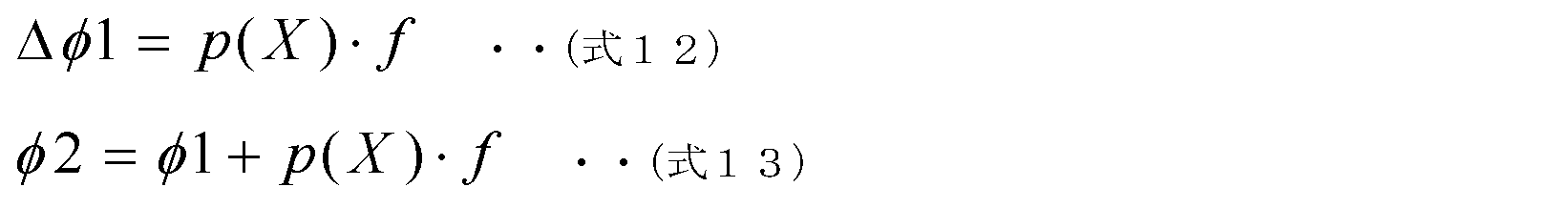
また、位相差Δφ1も、記憶部16に記憶された情報の参照に基づいて特定されてもよい。例えば、第1距離D1及び第2距離D2の差Xとした場合に、Xと位相補正係数p(X)とが対応付けられた情報(例えば、テーブル情報)が記憶部16にあらかじめ記憶されてもよい。この場合、制御部17は、第1距離D1及び第2距離D2の差Xに対応する位相補正係数を特定すれば、位相差Δφ1を以下の(式12)に基づいて算出することができる。なお、補正量φ2は、以下の(式13)に基づいて算出される。
Further, the phase difference Δφ1 may also be specified based on reference to information stored in the
このように、記憶部16にあらかじめ記憶された情報が参照されれば、模擬伝達特性C1の補正処理における演算量を抑制することができる。また、模擬伝達特性が記憶部16に複数セット記憶される構成よりも記憶部16に必要な記憶容量を低減することができる。
By referring to the information stored in advance in the
ところで、上記実施の形態では、模擬伝達特性C1の位相の補正量が変更されたが、模擬伝達特性C1のゲインの補正量が変更されてもよい。また、上記実施の形態では、第1距離D1と第2距離D2との差に基づいて模擬伝達特性C1の補正が行われたが第2距離D2のみに基づいて模擬伝達特性C1の補正が行われてもよい。具体的には、例えば、第2距離D2と位相補正係数とが対応付けられた情報に基づいて模擬伝達特性C1が補正されてもよい。 By the way, in the above embodiment, the phase correction amount of the simulated transfer characteristic C1 is changed, but the gain correction amount of the simulated transfer characteristic C1 may be changed. In the above embodiment, the simulated transfer characteristic C1 is corrected based on the difference between the first distance D1 and the second distance D2, but the simulated transfer characteristic C1 is corrected based only on the second distance D2 . may be performed. Specifically, for example, the simulated transfer characteristic C1 may be corrected based on information in which the second distance D2 and the phase correction coefficient are associated with each other.
また、騒音低減装置10が第3更新部及び第4更新部を備える場合(図4B参照)、模擬伝達特性C1の補正処理に加えて、ステップサイズパラメータまたはアルファ係数が変更されてもよい。例えば、制御部17は、スピーカSPの第1位置及びマイクロフォンMの第2位置が基準位置関係でないときのステップサイズパラメータの値を、第1位置及び第2位置が基準位置関係であるときのステップサイズパラメータの値よりも小さく(例えば、1/2倍)してもよい。また、制御部17は、スピーカSPの第1位置及びマイクロフォンMの第2位置が基準位置関係でないときのα係数の値を、第1位置及び第2位置が基準位置関係であるときのα係数の値よりも大きく(例えば、2倍)してもよい。
Further, when the
このように模擬伝達特性C1の補正処理に加えてステップサイズパラメータまたはα係数の値を変更することで、消音効果の確保やあるいは安定性を調整することができ、抑制された演算量でも機能を維持することができる。これらの値の変更は、移動量に比例して変更してもよいし、移動量に応じたデータテーブルを持ちそれを参照して変更してもよい。変更する値の量は騒音状態やシステム構成に応じて設定する。 In this way, by changing the value of the step size parameter or the α coefficient in addition to the correction processing of the simulated transfer characteristic C1 , it is possible to secure the noise reduction effect or adjust the stability, and it is possible to function even with a suppressed amount of calculation. can be maintained. These values may be changed in proportion to the amount of movement, or may be changed by referring to a data table corresponding to the amount of movement. The amount of value to change is set according to noise conditions and system configuration.
また、上記実施の形態では、スピーカSPの第1位置は固定され、マイクロフォンMの第2位置が変動したが、スピーカSPの第1位置が変動し、マイクロフォンMの第2位置が固定されていてもよい。例えば、スピーカSPが座席に取り付けられ、マイクロフォンMがダッシュボード等に取り付けられてもよい。また、スピーカSPの第1位置及びマイクロフォンMの第2位置の両方が変動してもよい。 Further, in the above embodiment, the first position of the speaker SP is fixed and the second position of the microphone M is changed, but the first position of the speaker SP is changed and the second position of the microphone M is fixed. good too. For example, the speaker SP may be attached to the seat and the microphone M may be attached to the dashboard or the like. Also, both the first position of the speaker SP and the second position of the microphone M may be changed.
また、スピーカSP及びマイクロフォンMの少なくとも一方は、座席ST以外の部分に取り付けられてもよい。例えば、スピーカSP及びマイクロフォンMの少なくとも一方は、ユーザの操作等によって位置及び姿勢の少なくとも一方が変化する構造体に取り付けられればよい。 Also, at least one of the speaker SP and the microphone M may be attached to a portion other than the seat ST. For example, at least one of the speaker SP and the microphone M may be attached to a structure that changes at least one of its position and posture by user's operation or the like.
[キャンセル音を制限する処理の第一の例]
以下、ステップS25のキャンセル音を制限する処理の詳細について説明する。ドアDR0~DR4の少なくとも1つのドアが開くと、当該ドアに取り付けられたスピーカSPの位置が変化する。しかしながら、ドアの状態を示すドア状態信号は、ドアの移動量(言い換えれば、開き量。具体的には、開き角度など。)を含まない状態信号である。したがって、ドアが開いたときに、座席STが移動した場合と同様の手法で伝達特性を補正することは困難である。そこで、制御部17は、ドアが開いたときには、キャンセル音を制限する処理を行う。
[First example of processing for limiting cancel sound]
Details of the processing for limiting the cancel sound in step S25 will be described below. When at least one of the doors DR0-DR4 is opened, the position of the speaker SP attached to that door changes. However, the door state signal indicating the state of the door is a state signal that does not include the amount of movement of the door (in other words, the amount of opening, specifically the opening angle, etc.). Therefore, when the door is opened, it is difficult to correct the transfer characteristics in the same manner as when the seat ST moves. Therefore, when the door is opened, the
発明者らが検討に用いた車両50においては、2列目のドア(DR2及びDR3)が開いたときの1列目のドアスピーカ(スピーカSP0、及び、スピーカSP1)から1列目のマイクロフォン(マイクロフォンM0及びマイクロフォンM1)への伝達特性は変化が小さい。したがって、2列目のドア(ドアDR2及びドアDR3)が開いたときに1列目のドアスピーカ(スピーカSP0、及び、スピーカSP1)からキャンセル音が出力されることは問題ない。
In the
一方、2列目のドア(ドアDR2及びドアDR3)が開いたときには、2列目のドアスピーカ(スピーカSP2、及び、スピーカSP3)から2列目のマイクロフォン(マイクロフォンM2)への伝達特性は変化が大きい。したがって、2列目のドア(ドアDR2及びドアDR3)が開いたときに2列目のドアスピーカ(スピーカSP2、及び、スピーカSP3)からキャンセル音が出力されると、十分に騒音を低減できないか、あるいは、キャンセル音自体が異音となってしまう可能性がある。 On the other hand, when the second row doors (doors DR2 and DR3) are opened, the transfer characteristics from the second row door speakers (speakers SP2 and SP3) to the second row microphones (microphone M2) change. is large. Therefore, if the canceling sound is output from the second row door speakers (speakers SP2 and SP3) when the doors on the second row (doors DR2 and DR3) are opened, the noise can be sufficiently reduced. Alternatively, the cancel sound itself may become an abnormal sound.
また、バックドア(ドアDR4)が開いたときには、スピーカSP4から2列目のマイクロフォン(マイクロフォンM2)への伝達特性の変化は小さいが、及び、スピーカSP4から3列目のマイクロフォン(マイクロフォンM3)への伝達特性の変化は大きい。したがって、バックドア(ドアDR4)が開いたときにスピーカSP4からキャンセル音が出力されと、十分に騒音を低減できないか、あるいは、キャンセル音自体が異音となってしまう可能性がある。 Also, when the back door (door DR4) is opened, the change in the transfer characteristics from the speaker SP4 to the second row microphone (microphone M2) is small, and from the speaker SP4 to the third row microphone (microphone M3). change in transfer characteristics is large. Therefore, if the cancellation sound is output from the speaker SP4 when the back door (door DR4) is opened, there is a possibility that the noise cannot be sufficiently reduced, or that the cancellation sound itself becomes an abnormal noise.
以上のような知見に基づき、発明者らが見出したキャンセル音を制限する処理について説明する。図10は、キャンセル音を制限する処理の第一の例のフローチャートである。図10に示される例では、1列目のドアスピーカ、及び、1列目のマイクロフォン以外のスピーカ及びマイクロフォンを制御対象とした処理について説明される。しかしながら、1列目のドアが開いた場合には、全座席での伝達特性の変化が激しいため制御(キャンセル音の出力)を完全に停止する、といった処理が行われてもよい。また、以下の図10の説明では、ドア状態信号には、ドアの識別情報(当該ドア状態信号が、ドアDR0~ドアDR4のいずれのドアの状態を示しているかを表す情報)が含まれるものとする。 Based on the knowledge as described above, the processing for limiting the canceling sound discovered by the inventors will be described. FIG. 10 is a flowchart of a first example of processing for limiting cancel sounds. In the example shown in FIG. 10, the process for controlling the door speakers in the first row and the speakers and microphones other than the microphones in the first row will be described. However, when the door of the first row is opened, a process of completely stopping the control (output of the canceling sound) may be performed because the change in the transfer characteristics of all the seats is drastic. Further, in the following description of FIG. 10, the door status signal includes door identification information (information indicating which of the doors DR0 to DR4 the door status signal indicates). and
制御部17は、ドア状態信号を取得すると、記憶部16に記憶されるドア状態情報を、取得したドア状態信号に応じて更新する(S41)。ドア状態情報は、ドアDR0~ドアDR4のそれぞれが開状態であるか閉状態であるかを示す情報(例えば、テーブル情報)である。ドア状態情報は、ドア状態信号(より詳細には、ドアの識別情報を含むドア状態信号)が取得されるごとに更新される。
Upon acquiring the door state signal, the
次に、制御部17は、記憶部16に記憶されているドア状態情報を参照し、現在開放されているドアがドアDR2~DR4のうちドアDR2及びドアDR3の少なくとも1つのみであるか否かを判定する(S42)。制御部17は、現在開放されているドアがドアDR2及びドアDR3のいずれかのみであると判定すると(S42でYes)、スピーカSP2及びSP3からのキャンセル音の出力を停止させる(S43)。制御部17は、具体的には、スピーカSP2及びSP3にキャンセル信号を出力する適応フィルタ部13の動作を、当該適応フィルタ部13のフィルタ係数を更新するフィルタ係数更新部15を制御することにより停止させる。なお、制御部17は、どのような方法でスピーカSP2及びSP3からのキャンセル音の出力を停止させてもよい。
Next, the
制御部17は、現在開放されているドアがドアDR2及びドアDR3の少なくとも1つのみではないと判定すると(S42でNo)、現在開放されているドアがドアDR2~DR4のうちドアDR4のみであるか否かを判定する(S44)。
When the
制御部17は、現在開放されているドアがドアDR4のみであると判定すると(S44でYes)、スピーカSP4からのキャンセル音の出力を停止させる(S45)。制御部17は、具体的には、スピーカSP4にキャンセル信号を出力する適応フィルタ部13の動作を、当該適応フィルタ部13のフィルタ係数を更新するフィルタ係数更新部15を制御することにより停止させる。なお、制御部17は、どのような方法でスピーカSP4からのキャンセル音の出力を停止させてもよい。
When the
また、制御部17は、マイクロフォンM3からの誤差信号をミュートする(S46)。制御部17は、具体的には、マイクロフォンM3から誤差信号を取得する適応フィルタ部13を制御することにより、マイクロフォンM3からの誤差信号を無効(ミュート)にする。なお、制御部17は、どのような方法でマイクロフォンM3からの誤差信号をミュートしてもよい。
Also, the
さらに、制御部17は、スピーカSP2及びスピーカSP3から出力されるキャンセル音により低減される騒音の周波数を、エンジン51の回転数800rpm以上1200rpm以下相当の周波数帯域に限定する(S47)。制御部17は、具体的には、周波数検出部12aによって検出される騒音の周波数をモニタし、騒音の周波数が回転数換算で800rpm未満あるいは1200rpmより大きい値に相当するときには、スピーカSP2及びスピーカSP3からのキャンセル音の出力を停止させる。制御部17は、騒音の周波数が回転数換算で800rpm以上1200rpm以下に相当するときには、スピーカSP2及びスピーカSP3から通常通りキャンセル音を出力させる。なお、制御部17は、どのような方法で対象となる騒音の周波数を限定してもよい。
Further, the
一方、制御部17は、ステップS44において、現在開放されているドアがドアDR4のみでないと判定すると(S44でNo)、スピーカSP2、スピーカSP3、及び、スピーカSP4からのキャンセル音の出力を停止させ(S48)、かつ、マイクロフォンM2、及び、マイクロフォンM3からの誤差信号をミュートする(S49)。キャンセル音の出力の停止方法、及び、誤差信号のミュート方法は上述の通りである。
On the other hand, when the
以上説明したように、制御部17は、ステップS25において、スピーカからのキャンセル音の出力を停止させる制御、マイクロフォンから出力される誤差信号をミュートする制御、及び、キャンセル音の対象となる騒音の周波数帯域を制限する制御などを行う。これにより、十分な騒音低減効果を得られないこと、及び、キャンセル音自体が異音となってしまうことが抑制される。
As described above, in step S25, the
[キャンセル音を制限する処理の第二の例]
ステップS25のキャンセル音を制限する処理は、テーブル情報(言い換えれば、制御マトリクス)を用いて行われてもよい。図11は、キャンセル音を制限する処理の第二の例のフローチャートである。図12は、スピーカ制御用テーブル情報の第一の例を示す図である。図13は、マイク制御用テーブル情報の第一の例を示す図である。スピーカ制御用テーブル情報、及び、マイク制御用テーブル情報は、記憶部16にあらかじめ記憶される。
[Second example of processing for limiting cancel sound]
The process of limiting the cancel sound in step S25 may be performed using table information (in other words, control matrix). FIG. 11 is a flow chart of a second example of processing for limiting cancel sounds. FIG. 12 is a diagram showing a first example of speaker control table information. FIG. 13 is a diagram showing a first example of microphone control table information. The speaker control table information and the microphone control table information are pre-stored in the
制御部17は、ドア状態信号を取得すると、記憶部16に記憶されるドア状態情報を、取得したドア状態信号に応じて更新する(S51)。
When acquiring the door state signal, the
次に、制御部17は、更新されたドア状態情報に加えて、スピーカ制御用テーブル情報、及び、マイク制御用テーブル情報に基づいて制御内容を決定する(S52)。図12に示されるように、スピーカ制御用テーブル情報の第一の例においては、各ドアの状態(より詳細には、開放されているドアの識別情報)と、スピーカSP0~SP4のそれぞれを動作停止させるか否かとが対応付けられている。また、図13に示されるように、マイク制御用テーブル情報の第一の例においては、各ドアの状態と、マイクロフォンM0~M3のそれぞれを動作停止させるか否かとが対応付けられている。なお、スピーカSPを停止させるとは、スピーカSPからのキャンセル音の出力を停止させることを意味し、マイクロフォンMを動作停止させるとは、マイクロフォンMから出力される誤差信号を無効にする(ミュートする)ことを意味する。スピーカSPからのキャンセル音の出力を停止させる方法、及び、マイクロフォンMを動作停止させる方法は、上述の通りである。
Next, the
例えば、ドア状態情報が5つのドアDR0~DR4のうちドアDR0のみが開放されていることを示す場合、制御部17は、スピーカSP0~SP4のうち、スピーカSP0及びスピーカSP1のみを停止させ、かつ、マイクロフォンM0~M3のうち、マイクロフォンM0及びマイクロフォンM1のみを停止させるように制御内容を決定する。
For example, when the door state information indicates that only the door DR0 is open among the five doors DR0 to DR4, the
また、ドア状態情報が5つのドアのうちドアDR1およびドアDR2のみが開放されていることを示す場合、制御部17は、スピーカSP0~SP3を停止させてスピーカSP4のみを動作させ、かつ、マイクロフォンM0~M2を停止させてマイクロフォンM3のみを動作させるように制御内容を決定する。そして、制御部17は、ステップS52で決定した制御内容に基づいて、キャンセル音の出力を制限する(S53)。つまり、制御部17は、決定した制御内容の通りの制御を行う。
Further, when the door state information indicates that only the doors DR1 and DR2 of the five doors are open, the
以上説明したように、制御部17は、複数のスピーカSP0~SP4のうちどのスピーカからのキャンセル音を停止させるか、及び、複数のマイクロフォンM0~M3のうちどのマイクロフォンからの誤差信号をミュートするかを、ドア状態情報(言い換えれば、ドアの識別情報を含むドア状態信号)、及び、テーブル情報に基づいて変更する。このようにスピーカ制御用テーブル情報、及び、マイク制御用テーブル情報を使用して制御内容を決定する方法によれば、制御内容の決定アルゴリズムを簡略化することにより、記憶部16の記憶容量の低減、及び、処理負荷の低減を実現することができる。
As described above, the
[キャンセル音を制限する処理の第三の例]
上記図11のフローチャートにおいて、図12及び図13に示されるテーブル情報と別の、図14及び図15に示されるようなテーブル情報が用いられてもよい。図14は、スピーカ制御用テーブル情報の第二の例を示す図である。図15は、マイク制御用テーブル情報の第二の例を示す図である。
[Third example of processing for limiting cancel sound]
In the flowchart of FIG. 11, table information as shown in FIGS. 14 and 15, which is different from the table information shown in FIGS. 12 and 13, may be used. FIG. 14 is a diagram showing a second example of speaker control table information. FIG. 15 is a diagram showing a second example of microphone control table information.
図14に示されるように、スピーカ制御用テーブル情報の第二の例においては、各ドアの状態と、スピーカSP0~SP4のそれぞれを動作停止させる周波数帯域(つまり、騒音の周波数帯域)とが対応付けられている。また、図15に示されるように、マイク制御用テーブル情報の第二の例においては、各ドアの状態と、マイクロフォンM0~M3のそれぞれを動作停止させる周波数帯域(つまり、騒音の周波数帯域)とが対応付けられている。なお、本実施の形態では、騒音低減装置10は、1Hz以上300Hz以下の周波数の騒音を対象としており、テーブル情報において1Hz以上300Hz以下と記載されている箇所は、動作停止と実質的に同一の意味である。
As shown in FIG. 14, in the second example of the speaker control table information, the state of each door corresponds to the frequency band for stopping the operation of each of the speakers SP0 to SP4 (that is, the noise frequency band). attached. Further, as shown in FIG. 15, in the second example of the microphone control table information, the state of each door and the frequency band for stopping the operation of each of the microphones M0 to M3 (that is, the noise frequency band) are associated. In the present embodiment, the
例えば、ドア状態情報が5つのドアDR0~DR4のうちドアDR0が開放されていることを示す場合、制御部17は、スピーカSP0~SP4のうち、スピーカSP0及びスピーカSP1のみを停止させ、かつ、マイクロフォンM0~M3のうち、マイクロフォンM0及びマイクロフォンM1のみを停止させる。さらに、制御部17は、マイクロフォンM2の動作を騒音の周波数が1Hz以上70Hz以下のときに停止させ、マイクロフォンM3の動作を騒音の周波数が1Hz以上60Hz以下のときに停止させる。つまり、マイクロフォンM2の動作は、騒音の周波数が70Hzよりも大きいときには通常動作であり、マイクロフォンM3の動作は、騒音の周波数が60Hzよりも大きいときには通常動作である。
For example, when the door status information indicates that the door DR0 is open among the five doors DR0 to DR4, the
また、ドア状態情報が5つのドアDR0~DR4のうちドアDR1およびドアDR2が開放されていることを示す場合、制御部17は、スピーカSP0~SP3を停止させてスピーカSP4のみを動作させ、かつ、マイクロフォンM0~M2を停止させてマイクロフォンM3のみを動作させるように制御内容を決定する。さらに、制御部17は、スピーカSP4の動作を騒音の周波数が65Hz以上100Hz以下のときに停止させる。スピーカSP4の動作は、騒音の周波数が65Hz未満、及び、騒音の周波数が100Hzよりも大きいときには通常動作である。
Further, when the door state information indicates that the door DR1 and the door DR2 among the five doors DR0 to DR4 are open, the
以上説明したように、制御部17は、ドア状態情報(言い換えれば、ドアの識別情報を含むドア状態信号)、及び、テーブル情報に基づいて、複数のスピーカSP0~SP4及び複数のマイクロフォンM0~M3の少なくとも一部の動作を、騒音の周波数がテーブル情報において定められた(つまり、所定の)周波数であるときに停止させる。このようにスピーカ制御用テーブル情報、及び、マイク制御用テーブル情報を使用して周波数帯域が制限される方法によれば、騒音低減装置10は、アルゴリズムを簡略化しつつもより綿密に制御内容を決定することができる。なお、図14及び図15のテーブル情報において、スピーカSPまたはマイクロフォンMの動作が停止される範囲は、周波数に代えて回転数で指定されてもよい。
As described above, the
[キャンセル音を制限する処理の第四の例]
ステップS25のキャンセル音を制限する処理は、ADF(つまり、適応フィルタ部13及びフィルタ係数更新部15)制御用テーブル情報を用いて行われてもよい。図16は、キャンセル音を制限する処理の第四の例のフローチャートである。図17は、ADF制御用のテーブル情報の一例を示す図である。ADF制御用テーブル情報は、記憶部16にあらかじめ記憶される。
[Fourth example of processing for limiting cancel sound]
The process of limiting the cancel sound in step S25 may be performed using ADF (that is,
制御部17は、ドア状態信号を取得すると、記憶部16に記憶されるドア状態情報を、取得したドア状態信号に応じて更新する(S61)。
Upon acquiring the door state signal, the
次に、制御部17は、更新されたドア状態情報に加えて、ADF制御用テーブル情報に基づいて制御内容を決定する(S62)。図17に示されるように、ADF制御用テーブル情報においては、各ドアの状態と、ADFの制御内容とが対応付けられている。ADFの制御内容は、具体的には、ステップサイズパラメータμを通常動作時の1/2倍にする(つまり、フィルタ係数の更新量を減らす)制御、及び、α係数を通常動作時の2倍にする制御である。図17において、スピーカSP0用ADF(以下ADF0とも記載される)とは、スピーカSP0にキャンセル信号を出力する適応フィルタ部13の意味である。ここでのADF0には、スピーカSP0にキャンセル信号を出力する適応フィルタ部13、及び、当該適応フィルタ部13のフィルタ係数を更新するフィルタ係数更新部15の両方が含まれてもよい。
Next, the
例えば、ドア状態情報が5つのドアのうちドアDR0のみが開放されていることを示す場合、制御部17は、ADF0~ADF4のうち、ADF0及びADF1を停止させ、ADF2及びADF3をステップサイズパラメータμを通常動作時の1/2倍にして動作させ、ADF4を通常動作させるように制御内容を決定する。
For example, when the door status information indicates that only door DR0 is open among five doors, the
また、ドア状態情報が5つのドアのうちドアDR1およびドアDR2のみが開放されていることを示す場合、制御部17は、ADF0~ADF3を停止させ、ADF4をステップサイズパラメータμを通常動作時の1/2倍にして動作させるように制御内容を決定する。そして、制御部17は、ステップS62で決定した制御内容に基づいて、キャンセル音の出力を制限する(S63)。つまり、制御部17は、決定した制御内容の通りの制御を行う。
Further, when the door status information indicates that only the doors DR1 and DR2 of the five doors are open, the
以上説明したように、制御部17は、複数のスピーカSP0~SP4に対応する複数のADF0~ADF4のうちどのADFに対して通常と異なる動作をさせるかを、ドア状態情報(言い換えれば、ドアの識別情報を含むドア状態信号)、及び、テーブル情報に基づいて変更する。通常と異なる動作とは、例えば、フィルタ係数の更新量を決定するためのステップサイズパラメータを補正してADFを動作させること、及び、α係数を補正してADFを動作させることなどである。このように制御用テーブル情報を使用してADFの制御内容を決定する方法によれば、制御内容の決定アルゴリズムを簡略化しつつ、ADFを制御することができる。
As described above, the
(実施の形態2)
[構成]
以下、実施の形態2に係る騒音低減装置の構成について説明する。図18は、実施の形態2に係る騒音低減装置の機能構成を示すブロック図である。なお、以下の実施の形態2では、実施の形態1で既出の事項については説明が省略または簡略化される。
(Embodiment 2)
[composition]
The configuration of the noise reduction device according to Embodiment 2 will be described below. 18 is a block diagram showing a functional configuration of a noise reduction device according to Embodiment 2. FIG. It should be noted that, in the second embodiment below, descriptions of matters already mentioned in the first embodiment are omitted or simplified.
図18に示されるように、騒音低減装置110は、適応フィルタ部13の出力とキャンセル信号出力端子11cとの間に、出力信号処理部18を備える点が騒音低減装置10と異なる。
As shown in FIG. 18, the
出力信号処理部18は、適応フィルタ部13から出力されるキャンセル信号の振幅の最大値(言い換えれば、出力レベルの最大値)を閾値以下に制限するリミッタ回路である。出力信号処理部18を作動させてキャンセル信号の振幅に制限をかける(出力信号処理部18をオンする)か、出力信号処理部18を作動させずにキャンセル信号をそのままキャンセル信号出力端子11cへ出力する(出力信号処理部18をオフする)かは、制御部17によって制御される。出力信号処理部18は、例えば、制限をかける際に、キャンセル信号が閾値より大きい場合はフェードアウト処理を行い、急激に信号の振幅が制限されて異音が発生することを抑制する。また、上記閾値についても、制御部17によって変更可能である。
The output
また、騒音低減装置110は、誤差信号入力端子11bとフィルタ係数更新部15の入力との間に、入力信号処理部19を備える点も騒音低減装置10と異なる。
The
入力信号処理部19は、誤差信号にフェードアウト処理(誤差信号を所定時間をかけて減衰させる処理)を行った後に通常時より低いゲイン係数を用いて誤差信号を減衰させるゲイン調整回路である。入力信号処理部19を作動させて誤差信号にフェードアウト処理を行うか否かは、制御部17によって制御される。なお、入力信号処理部19は、誤差信号をミュートすることもできる。
The input
また、入力信号処理部19は、誤差信号にフェードイン処理(誤差信号を所定時間をかけて増大させる処理)を行った後に通常時のゲイン係数に復帰することもできる。入力信号処理部19を作動させて誤差信号にフェードイン処理を行うか否かは、制御部17によって制御される。
Further, the input
[キャンセル音を制限する処理の第五の例]
騒音低減装置110は、ステップS25のキャンセル音を制限する処理に、出力信号処理部18を使用することができる。図19は、キャンセル音を制限する処理の第五の例のフローチャートである。
[Fifth example of processing for limiting cancellation sound]
The
制御部17は、ドア状態信号を取得すると、記憶部16に記憶されるドア状態情報を、取得したドア状態信号に応じて更新する(S71)。制御部17は、更新されたドア状態情報を参照することにより、ドアDR4が開放されていると判定すると(S72)、スピーカSP4にキャンセル信号を出力する出力信号処理部18を作動する(S73)。この場合、通常動作時は、出力信号処理部18は作動していない。なお、出力信号処理部18は、常時動作しており、制御部17は、ドアDR4が開放されていると判定されたときに、スピーカSP4にキャンセル信号を出力する出力信号処理部18の閾値を低下させてもよい。
Upon acquiring the door state signal, the
以上説明したように、騒音低減装置110の制御部17は、ステップS25において、スピーカSP4からのキャンセル音の出力レベルを制限する。このように出力信号処理部18を使用してキャンセル音を制限する方法によれば、キャンセル音の出力を完全に停止させることなく、キャンセル音が異音になってしまうことを抑制することができる。
As described above, the
なお、制御部17は、出力信号処理部18の閾値を、騒音の周波数に応じて変化させてもよい。これにより、騒音低減装置110は、伝達特性の変化が小さい周波数帯域では、出力信号処理部18の閾値を下げずに通常動作に近い動作を行うことができる。
Note that the
また、図19では、ドアDR4が開放されていると判定されたときに、スピーカSP4にキャンセル信号を出力する出力信号処理部18を作動する例が示されている。しかしながら、図19は例示に過ぎず、例えば、実施の形態1と同様に、各ドアの状態と、スピーカSP0~SP4に対応する複数の出力信号処理部18の制御内容とが対応付けられたテーブル情報を用いて出力信号処理部18が制御されてもよい。
Further, FIG. 19 shows an example of operating the output
[キャンセル音を制限する処理の第六の例]
騒音低減装置110は、ステップS25のキャンセル音を制限する処理に、入力信号処理部19を使用することができる。図20は、キャンセル音を制限する処理の第六の例のフローチャートである。
[Sixth example of processing for limiting cancel sound]
The
制御部17は、ドア状態信号を取得すると、記憶部16に記憶されるドア状態情報を、取得したドア状態信号に応じて更新する(S81)。制御部17は、更新されたドア状態情報を参照することにより、ドアDR4が開放されたと判定すると(S82)、マイクロフォンM3から誤差信号を取得する入力信号処理部19に、当該誤差信号へのフェードアウト処理を行わせる(S83)。フェードアウト処理により誤差信号に対するゲインは第一所定期間をかけて徐々に減少し、所定のゲインへ減衰し第一所定期間の終了時点以降は一定となる。このゲインは、ドアDR4が閉鎖されるまで維持される。
Upon acquiring the door state signal, the
その後、制御部17は、ドア状態信号を取得すると、記憶部16に記憶されるドア状態情報を、取得したドア状態信号に応じて更新する(S84)。制御部17は、更新されたドア状態情報を参照することにより、ドアDR4が閉鎖されたと判定すると(S85)、マイクロフォンM3から誤差信号を取得する入力信号処理部19に、当該誤差信号へのフェードイン処理を行わせる(S86)。フェードイン処理により誤差信号に対するゲインは第二所定期間をかけて徐々に増加し、第二所定期間の終了時点以降は通常動作時と同一(つまり、ステップS83のフェードアウト処理が行われる前と同一)の値で一定となる。第一所定期間と第二所定期間の長さは、同一であってもよいし異なってもよい。
After that, when the door state signal is acquired, the
以上説明したように、騒音低減装置110の制御部17は、ステップS25において、マイクロフォンM3から出力される誤差信号にフェード処理を行う。例えば、誤差信号は、フェードアウト処理により減衰される。入力信号処理部19によって誤差信号が減衰されれば、安定性が下がるようなキャンセル信号が生成されてしまうことが抑制される。また、誤差信号にフェード処理が行われることで、誤差信号の急激な変化による異音の発生が抑制される。
As described above, the
なお、図20では、ドアDR4が開放されていると判定されたときに、マイクロフォンM3から出力される誤差信号を取得する入力信号処理部19を作動する例が示されている。しかしながら、図20は例示に過ぎず、例えば、実施の形態1と同様に、各ドアの状態と、マイクロフォンM0~M3に対応する複数の入力信号処理部19の制御内容とが対応付けられたテーブル情報を用いて入力信号処理部19が制御されてもよい。
Note that FIG. 20 shows an example in which the input
以上説明したように、実施の形態2では、出力信号処理部18及び入力信号処理部19を追加することにより、第一~第四の例で示したような入力信号および出力信号を停止する方法に比べて調整範囲が広くなり、可能な限り消音性能を保持するような制御が可能となる。
As described above, in the second embodiment, by adding the output
(まとめ)
以上説明したように、騒音低減装置10は、移動体装置の内部の空間56における騒音を低減する騒音低減装置である。騒音低減装置10は、騒音と相関を有する参照信号が入力される参照信号入力端子11aと、入力された参照信号に基づいて特定される周波数を有する基準信号に逐次更新される係数を有する適応フィルタを適用する処理を行うことにより、騒音を低減するためのキャンセル音の出力に用いられるキャンセル信号を生成する適応フィルタ部13と、生成されたキャンセル信号を空間56に設けられたスピーカSPに出力するためのキャンセル信号出力端子11cと、移動体装置に設けられた可動部の状態を示す状態信号が入力される状態信号入力端子11dと、入力された状態信号により可動部が所定の基準状態でないことが示される場合に、当該状態信号に可動部の移動量を示す情報が含まれるか否かに応じて、キャンセル音の出力に関する互いに異なる制御を行う制御部17とを備える。参照信号入力端子11aは、参照信号入力部の一例であり、キャンセル信号出力端子11cは、キャンセル信号出力部の一例であり、状態信号入力端子11dは、状態信号入力部の一例である。
(summary)
As described above, the
このような騒音低減装置10は、可動部の移動量を示す情報の有無に応じて適切な制御を行うことにより、空間56における騒音制御が不安定になることを抑制することができる。
Such a
また、例えば、制御部17は、入力された状態信号に可動部の移動量を示す情報が含まれると判定した場合に、上記制御として、上記係数の更新に用いられる模擬伝達特性C1を移動量に基づいて補正する。
Further, for example, when the
このような騒音低減装置10は、可動部の移動量を示す情報が得られる場合に、当該情報を利用して模擬伝達特性C1を補正することにより、空間56における騒音制御が不安定になることを抑制することができる。
When information indicating the amount of movement of the movable portion is obtained, such a
また、例えば、適応フィルタの係数は、適応フィルタ部13の出力に別の係数(α係数)をかけた信号及び基準信号を用いて更新される。
Also, for example, the coefficient of the adaptive filter is updated using a signal obtained by multiplying the output of the
このような騒音低減装置10は、騒音制御を安定させることができる。
Such a
また、例えば、制御部17は、入力された状態信号に可動部の移動量を示す情報が含まれると判定した場合に別の係数(α係数)およびステップサイズパラメータを補正する。
Further, for example, the
このような騒音低減装置10は、α係数またはステップサイズパラメータを補正することで、空間56における騒音制御が不安定になることを抑制することができる。
Such a
また、例えば、制御部17は、入力された状態信号に可動部の移動量を示す情報が含まれないと判定した場合に、上記制御として、スピーカSPからのキャンセル音の出力を停止させる。
Further, for example, when the
このような騒音低減装置10は、可動部の移動量を示す情報が得られない場合に、キャンセル音を停止することで、空間56における騒音制御が不安定になることを抑制することができる。
Such a
また、例えば、制御部17は、入力された状態信号に可動部の移動量を示す情報が含まれないと判定した場合に、上記制御として、空間56に設けられたマイクロフォンから出力される、上記係数を更新するための誤差信号をミュートする。
Further, for example, when the
このような騒音低減装置10は、可動部の移動量を示す情報が得られない場合に、誤差信号をミュートすることで、空間56における騒音制御が不安定になることを抑制することができる。
Such a
また、例えば、制御部17は、入力された状態信号に可動部の移動量を示す情報が含まれないと判定した場合に、上記制御として、キャンセル音の対象となる騒音の周波数帯域を、可動部が所定の基準状態であるときよりも制限する。
Further, for example, when the
このような騒音低減装置10は、可動部の移動量を示す情報が得られない場合に、キャンセル音の対象となる騒音の周波数帯域を制限することで、空間56における騒音制御が不安定になることを抑制することができる。
Such a
また、例えば、制御部17は、入力された状態信号に可動部の移動量を示す情報が含まれないと判定した場合に、上記制御として、上記係数の更新量を決定するためのステップサイズパラメータを補正する。
Further, for example, when the
このような騒音低減装置10は、可動部の移動量を示す情報が得られない場合に、ステップサイズパラメータを補正することで、空間56における騒音制御が不安定になることを抑制することができる。
Such a
また、例えば、適応フィルタの係数は、適応フィルタ部13の出力に別の係数(α係数)をかけた信号及び基準信号を用いて更新され、制御部17は、入力された状態信号に可動部の移動量を示す情報が含まれないと判定した場合に、上記制御として、上記別の係数(α係数)を補正する。
Further, for example, the coefficient of the adaptive filter is updated using a signal obtained by multiplying the output of the
このような騒音低減装置10は、可動部の移動量を示す情報が得られない場合に、α係数を補正することで、空間56における騒音制御が不安定になることを抑制することができる。
Such a
また、実施の形態2では、制御部17は、入力された状態信号に可動部の移動量を示す情報が含まれないと判定した場合に、上記制御として、スピーカSPからのキャンセル音の出力レベルを制限する。出力レベルの制限には、例えば、出力信号処理部18が用いられる。
Further, in the second embodiment, when the
このような騒音低減装置110は、可動部の移動量を示す情報が得られない場合に、キャンセル音の出力レベルを制限することで、空間56における騒音制御が不安定になることを抑制することができる。
Such a
また、実施の形態2では、制御部17は、入力された状態信号に可動部の移動量を示す情報が含まれないと判定した場合に、上記制御として、空間56に設けられたマイクロフォンから出力される、上記係数を更新するための誤差信号にフェード処理を行う。フェード処理には、例えば、入力信号処理部19が用いられる。
In addition, in the second embodiment, when the
このような騒音低減装置110は、可動部の移動量を示す情報が得られない場合に、誤差信号にフェード処理を行うことで、空間56における騒音制御が不安定になることを抑制することができる。
Such a
また、例えば、制御部17は、入力された状態信号に可動部の移動量を示す情報が含まれないと判定した場合に、入力された前記状態信号に含まれる前記可動部の識別情報に基づいて上記制御を行う。
Further, for example, when the
このような騒音低減装置10は、複数の可動部のうちどの可動部の状態が変化したかに応じて適切な制御を行うことにより、空間56における騒音制御が不安定になることを抑制することができる。
Such a
また、例えば、空間56には、キャンセル音を出力するための複数のスピーカSP0~SP4、及び、各々が上記係数を更新するための誤差信号を出力する複数のマイクロフォンM0~M3が設けられる。制御部17は、複数のスピーカSP0~SP4のうちどのスピーカからのキャンセル音を停止させるか、及び、複数のマイクロフォンM0~M3のうちどのマイクロフォンからの誤差信号をミュートするかを、上記識別情報に基づいて変更する上記制御を行う。例えば、制御部17は、複数のスピーカSP0~SP4のうち識別情報が示す可動部の最も近くに位置するスピーカからのキャンセル音を停止させる。また、例えば、制御部17は、複数のスピーカSP0~SP4のうち識別情報が示す可動部の最も近くに位置するマイクロフォンからの誤差信号をミュートする。
Further, for example, the
このような騒音低減装置10は、複数の可動部のうちどの可動部の状態が変化したかに応じて複数のスピーカSP0~SP4の少なくとも一部からのキャンセル音を停止することで、空間56における騒音制御が不安定になることを抑制することができる。また、騒音低減装置10は、複数の可動部のうちどの可動部の状態が変化したかに応じて複数のマイクロフォンM0~M3のうち少なくとも一部からの誤差信号をミュートすることで、空間56における騒音制御が不安定になることを抑制することができる。
Such a
また、例えば、空間56には、キャンセル音を出力するための複数のスピーカSP0~SP4、及び、各々が上記係数を更新するための誤差信号を出力する複数のマイクロフォンM0~M3が設けられ、制御部17は、上記識別情報に基づいて、複数のスピーカSP0~SP4及び複数のマイクロフォンM0~M3の少なくとも一部の動作を、騒音の周波数が所定の周波数であるときに停止させる上記制御を行う。
Further, for example, the
このような騒音低減装置10は、複数の可動部のうちどの可動部の状態が変化したかに応じて複数のスピーカ及び複数のマイクロフォンの少なくとも一部の動作を騒音の周波数が所定の周波数であるときに停止することで、空間56における騒音制御が不安定になることを抑制することができる。
Such a
また、例えば、空間56には、キャンセル音を出力するための複数のスピーカSP0~SP4が設けられる。制御部17は、複数のスピーカSP0~SP4に対応する複数の適応フィルタ部13(複数のADF0~ADF4)のうちどの適応フィルタ部13に対して通常と異なる動作をさせるかを、上記識別情報に基づいて変更する制御を行う。
Further, for example, the
このような騒音低減装置10は、複数の可動部のうちどの可動部の状態が変化したかに応じて複数のスピーカSP0~SP4及び複数のマイクロフォンM0~M3の少なくとも一部の動作を騒音の周波数が所定の周波数であるときに停止することで、空間56における騒音制御が不安定になることを抑制することができる。
Such a
また、例えば、上記移動体装置は、車両50であり、状態信号は、車両50に設けられたドアの状態、または、車両50に設けられた座席STの状態を示し、可動部の移動量を示す情報は、車両50に設けられたドアの状態を示すドア状態信号には含まれないが、車両50に設けられた座席STの状態を示す座席状態信号には含まれる。
Further, for example, the mobile device is a
このような移動体装置は、可動部がドアであるか座席であるかに応じて適切な制御を行うことにより、空間56における騒音制御が不安定になることを抑制することができる。
Such a mobile device can suppress unstable noise control in the
また、騒音低減装置10は、より詳細には、さらに、スピーカSPの位置からマイクロフォンMの位置までの伝達特性を模擬した模擬伝達特性を基準信号に適用した補正後基準信号を生成する補正部14と、マイクロフォンMから出力される誤差信号と、生成された補正後基準信号とを用いて、上記係数を逐次更新するフィルタ係数更新部15とを備える。
Further, more specifically, the
また、移動体装置は、騒音低減装置10と、スピーカSPとを備える。
The mobile device also includes a
このような移動体装置は、可動部の移動量を示す情報の有無に応じて適切な制御を行うことにより、空間56における騒音制御が不安定になることを抑制することができる。
Such a mobile device can suppress unstable noise control in the
また、騒音低減装置10などのコンピュータによって実行される騒音低減方法は、移動体装置の内部の空間における騒音を低減する騒音低減方法である。騒音低減方法は、騒音と相関を有する参照信号に基づいて特定される周波数を有する基準信号に逐次更新される係数を有する適応フィルタを適用する処理を行うことにより、騒音を低減するためのキャンセル音の出力に用いられるキャンセル信号を生成し、生成されたキャンセル信号を空間56に設けられたスピーカに出力し、移動体装置に設けられた可動部の状態を示す状態信号により可動部が所定の基準状態でないことが示される場合に、当該状態信号に可動部の移動量を示す情報が含まれるか否かに応じて、キャンセル音の出力に関する互いに異なる制御を行う。
Also, the noise reduction method executed by a computer such as the
このような騒音低減方法は、可動部の移動量を示す情報の有無に応じて適切な制御を行うことにより、空間56における騒音制御が不安定になることを抑制することができる。
Such a noise reduction method can suppress unstable noise control in the
(その他の実施の形態)
以上、実施の形態について説明したが、本発明は、上記実施の形態に限定されるものではない。
(Other embodiments)
Although the embodiments have been described above, the present invention is not limited to the above embodiments.
例えば、上記実施の形態で説明された模擬伝達特性を補正する処理と、上記実施の形態で説明されたキャンセル音を制限する処理とは並行して行われてもよい。つまり、座席の位置情報を用いた伝達特性の位相補正をしつつ、この状態でドアが開いたことにより一部の制御が停止されてもよい。 For example, the process of correcting the simulated transfer characteristic described in the above embodiment and the process of limiting the cancel sound described in the above embodiment may be performed in parallel. In other words, while correcting the phase of the transfer characteristics using the seat position information, part of the control may be stopped when the door is opened in this state.
また、上記実施の形態では、可動部として座席及びドアが例示されたが、可動部にはその他に、車両が備える開閉式のルーフなども含まれる。可動部は、移動体装置に設けられ、当該可動部が動くことにより移動体装置内の空間の伝達特性に影響を与える構造体であればよい。 In addition, in the above-described embodiments, the seat and the door were exemplified as the movable parts, but the movable parts also include an openable roof provided in the vehicle. The movable part may be a structure that is provided in the mobile device and that affects the transfer characteristics of the space inside the mobile device by the movement of the movable part.
また、上記実施の形態では、ドア状態信号にはドアの移動量を示す情報が含まれないと説明されたが、ドア状態信号にドアの移動量を示す情報が含まれてもよい。同様に、座席状態信号には、座席の移動量を示す情報が含まれると説明されたが、座席状態信号に座席の移動量を示す情報が含まれなくてもよい。 Further, in the above embodiment, it was explained that the door status signal did not include information indicating the amount of movement of the door, but the door status signal may include information indicating the amount of movement of the door. Similarly, although it has been described that the seat condition signal includes information indicating the amount of movement of the seat, the seat condition signal may not include information indicating the amount of movement of the seat.
また、上記実施の形態では、ドアにスピーカが設けられ、座席にマイクロフォンが設けられたが、スピーカの配置、及び、マイクロフォンの配置は特に限定されない。例えば、ドアにマイクロフォンが設けられ、座席にスピーカが設けられてもよい。また、スピーカ及びマイクロフォンが可動部に設けられることは必須ではなく、スピーカ及びマイクロフォンのそれぞれは、可動部の近傍、または、可動部以外の部分(例えば、ダッシュボードなどの可動しない部分)に設けられてもよい。 Further, in the above-described embodiment, the speaker is provided in the door and the microphone is provided in the seat, but the arrangement of the speaker and the arrangement of the microphone are not particularly limited. For example, the door may be provided with a microphone and the seat may be provided with a speaker. Further, it is not essential that the speaker and the microphone are provided on the movable part, and each of the speaker and the microphone is provided near the movable part or in a part other than the movable part (for example, a non-movable part such as a dashboard). may
上記実施の形態に係る騒音低減装置は、車両以外の移動体装置に搭載されてもよい。移動体装置は、例えば、航空機または船舶であってもよい。また、本発明は、このような車両以外の移動体装置として実現されてもよい。 The noise reduction device according to the above embodiment may be mounted on a mobile device other than a vehicle. A mobile device may be, for example, an aircraft or a ship. Also, the present invention may be implemented as a mobile device other than such a vehicle.
また、上記実施の形態では、騒音源としてエンジンが例示されたが、騒音源についても特に限定されない。騒音源は、例えば、モータなどであってもよい。 Moreover, although the engine was exemplified as the noise source in the above embodiment, the noise source is not particularly limited. The noise source may be, for example, a motor or the like.
また、上記実施の形態に係る騒音低減装置の構成は、一例である。例えば、騒音低減装置は、D/A変換器、ローパスフィルタ(LPF)、ハイパスフィルタ(HPF)、電力増幅器、または、A/D変換器などの構成要素を含んでもよい。 Also, the configuration of the noise reduction device according to the above embodiment is an example. For example, noise reduction devices may include components such as D/A converters, low pass filters (LPF), high pass filters (HPF), power amplifiers, or A/D converters.
また、上記実施の形態に係る騒音低減装置が行う処理は、一例である。例えば、上記実施の形態で説明された一部の処理が、デジタル信号処理ではなくアナログ信号処理によって実現されてもよい。 Also, the processing performed by the noise reduction device according to the above embodiment is an example. For example, some of the processing described in the above embodiments may be realized by analog signal processing instead of digital signal processing.
また、例えば、上記実施の形態において、特定の処理部が実行する処理を別の処理部が実行してもよい。また、複数の処理の順序が変更されてもよいし、複数の処理が並行して実行されてもよい。 Further, for example, in the above-described embodiments, the processing executed by a specific processing unit may be executed by another processing unit. In addition, the order of multiple processes may be changed, and multiple processes may be executed in parallel.
また、上記実施の形態において、各構成要素は、専用のハードウェアで構成されるか、各構成要素に適したソフトウェアプログラムを実行することによって実現されてもよい。各構成要素は、CPUまたはプロセッサなどのプログラム実行部が、ハードディスクまたは半導体メモリなどの記録媒体に記録されたソフトウェアプログラムを読み出して実行することによって実現されてもよい。 Further, in the above embodiments, each component may be implemented by dedicated hardware or by executing a software program suitable for each component. Each component may be realized by reading and executing a software program recorded in a recording medium such as a hard disk or a semiconductor memory by a program execution unit such as a CPU or processor.
また、各構成要素は、回路(または集積回路)でもよい。これらの回路は、全体として1つの回路を構成してもよいし、それぞれ別々の回路でもよい。また、これらの回路は、それぞれ、汎用的な回路でもよいし、専用の回路でもよい。 Each component may also be a circuit (or integrated circuit). These circuits may form one circuit as a whole, or may be separate circuits. These circuits may be general-purpose circuits or dedicated circuits.
また、本発明の全般的または具体的な態様は、システム、装置、方法、集積回路、コンピュータプログラムまたはコンピュータ読み取り可能なCD-ROMなどの非一時的な記録媒体で実現されてもよい。また、システム、装置、方法、集積回路、コンピュータプログラム及びコンピュータ読み取り可能な非一時的な記録媒体の任意な組み合わせで実現されてもよい。 Also, general or specific aspects of the present invention may be implemented in a system, apparatus, method, integrated circuit, computer program or non-transitory recording medium such as a computer-readable CD-ROM. Also, any combination of systems, devices, methods, integrated circuits, computer programs, and computer-readable non-transitory recording media may be implemented.
例えば、本発明は、騒音低減装置(DSP)などのコンピュータが実行する騒音低減方法として実現されてもよいし、上記騒音低減方法をコンピュータ(DSP)に実行させるためのプログラムとして実現されてもよい。また、本発明は、上記実施の形態に係る騒音低減装置と、スピーカ(出音装置)と、マイクロフォン(集音装置)とを備える騒音低減システムとして実現されてもよい。 For example, the present invention may be implemented as a noise reduction method executed by a computer such as a noise reduction device (DSP), or may be implemented as a program for causing a computer (DSP) to execute the noise reduction method. . Further, the present invention may be realized as a noise reduction system including the noise reduction device according to the above embodiments, a speaker (sound output device), and a microphone (sound collection device).
また、上記実施の形態において説明された騒音低減装置の動作における複数の処理の順序は一例である。複数の処理の順序は、変更されてもよいし、複数の処理は、並行して実行されてもよい。 Also, the order of a plurality of processes in the operation of the noise reduction device described in the above embodiment is an example. The order of multiple processes may be changed, and multiple processes may be executed in parallel.
その他、各実施の形態に対して当業者が思いつく各種変形を施して得られる形態、または、本発明の趣旨を逸脱しない範囲で各実施の形態における構成要素及び機能を任意に組み合わせることで実現される形態も本発明に含まれる。 In addition, forms obtained by applying various modifications to each embodiment that a person skilled in the art can think of, or realized by arbitrarily combining the constituent elements and functions of each embodiment without departing from the spirit of the present invention. Also included in the present invention.
本発明の騒音低減装置は、例えば、車室内の騒音を低減する装置として有用である。 INDUSTRIAL APPLICABILITY The noise reduction device of the present invention is useful, for example, as a device for reducing noise inside a vehicle.
10、110 騒音低減装置
11a 参照信号入力端子
11b 誤差信号入力端子
11c キャンセル信号出力端子
11d 状態信号入力端子
12 基準信号生成部
12a 周波数検出部
12b 正弦波生成部
12c 余弦波生成部
13 適応フィルタ部
13a 第1フィルタ
13b 第2フィルタ
13c 加算部
14 補正部
14a 補正制御部
14b 第1擬似参照信号生成部
14c 第2擬似参照信号生成部
15 フィルタ係数更新部
15a 第1更新部
15b 第2更新部
16 記憶部
17 制御部
18 信号制限部
19 信号処理部
30 受聴者
50 車両(移動体装置)
51 エンジン
52 エンジン制御部
53 ドア状態検出部
54 座席状態検出部
55 車両本体
56 空間
DR0~DR4 ドア
M、M0~M3 マイク
SP、SP0~SP4 スピーカ
ST、ST0~ST3 座席
10, 110
51
Claims (19)
前記騒音と相関を有する参照信号が入力される参照信号入力部と、
入力された前記参照信号に基づいて特定される周波数を有する基準信号に逐次更新される係数を有する適応フィルタを適用する処理を行うことにより、前記騒音を低減するためのキャンセル音の出力に用いられるキャンセル信号を生成する適応フィルタ部と、
生成された前記キャンセル信号を前記空間に設けられたスピーカに出力するためのキャンセル信号出力部と、
前記移動体装置に設けられた可動部の状態を示す状態信号が入力される状態信号入力部と、
入力された前記状態信号により前記可動部が所定の基準状態でないことが示される場合に、当該状態信号に前記可動部の移動量を示す情報が含まれるか否かに応じて、前記キャンセル音の出力に関する互いに異なる制御を行う制御部とを備える
騒音低減装置。 A noise reduction device for reducing noise in a space inside a mobile device,
a reference signal input unit into which a reference signal correlated with the noise is input;
It is used to output a cancellation sound for reducing the noise by performing a process of applying an adaptive filter having a coefficient that is sequentially updated to a reference signal having a frequency specified based on the input reference signal. an adaptive filter unit that generates a cancellation signal;
a cancellation signal output unit for outputting the generated cancellation signal to a speaker provided in the space;
a state signal input unit for receiving a state signal indicating a state of a movable unit provided in the mobile device;
When the input state signal indicates that the movable portion is not in a predetermined reference state, the cancellation sound is generated depending on whether or not the state signal includes information indicating the amount of movement of the movable portion. A noise reduction device comprising: a control unit that performs different controls regarding outputs.
請求項1に記載の騒音低減装置。 When the control unit determines that the input state signal includes information indicating the amount of movement of the movable unit, the control unit sets a simulated transfer characteristic used for updating the coefficient based on the amount of movement. The noise reduction device according to claim 1, wherein the correction is performed by
請求項2に記載の騒音低減装置。 The noise reduction device according to claim 2, wherein the coefficient of the adaptive filter is updated using a signal obtained by multiplying the output of the adaptive filter section by another coefficient and the reference signal.
請求項3に記載の騒音低減装置。 The noise reduction device according to claim 3, wherein the control section corrects the another coefficient and the step size parameter when determining that the input state signal includes information indicating the amount of movement of the movable section.
請求項1~4のいずれか1項に記載の騒音低減装置。 The control unit stops outputting a cancellation sound from the speaker as the control when determining that the input state signal does not include information indicating the amount of movement of the movable unit. 5. The noise reduction device according to any one of 4.
請求項1~4のいずれか1項に記載の騒音低減装置。 When the control unit determines that the input state signal does not include information indicating the amount of movement of the movable unit, the control unit adjusts the coefficient output from the microphone provided in the space as the control. A noise reduction device according to any one of claims 1 to 4, wherein the error signal for updating is muted.
請求項1~4のいずれか1項に記載の騒音低減装置。 When the control unit determines that the input state signal does not include information indicating the amount of movement of the movable unit, the control unit adjusts the frequency band of the noise that is the target of the cancellation sound to the The noise reduction device according to any one of claims 1 to 4, wherein the movable portion is restricted more than when it is in the predetermined reference state.
請求項1~4のいずれか1項に記載の騒音低減装置。 The control unit corrects a step size parameter for determining an update amount of the coefficient as the control when determining that the input state signal does not include information indicating the amount of movement of the movable unit. The noise reduction device according to any one of claims 1 to 4.
前記制御部は、入力された前記状態信号に前記可動部の移動量を示す情報が含まれないと判定した場合に、前記制御として、前記別の係数を補正する
請求項1~4のいずれか1項に記載の騒音低減装置。 the coefficients of the adaptive filter are updated using a signal obtained by multiplying the output of the adaptive filter unit by another coefficient and the reference signal;
The control unit corrects the another coefficient as the control when it is determined that the input state signal does not include information indicating the amount of movement of the movable unit. The noise reduction device according to item 1.
請求項1~4のいずれか1項に記載の騒音低減装置。 2. When the control unit determines that the input state signal does not include information indicating the amount of movement of the movable unit, the control unit limits the output level of a cancellation sound from the speaker as the control. 5. The noise reduction device according to any one of 1 to 4.
請求項1~4のいずれか1項に記載の騒音低減装置。 When the control unit determines that the input state signal does not include information indicating the amount of movement of the movable unit, the control unit adjusts the coefficient output from the microphone provided in the space as the control. The noise reduction device according to any one of claims 1 to 4, wherein fading processing is performed on the error signal for updating.
請求項1~4のいずれか1項に記載の騒音低減装置。 When the control unit determines that the input state signal does not include information indicating the amount of movement of the movable unit, the control unit performs the above-described operation based on the identification information of the movable unit included in the input state signal. The noise reduction device according to any one of claims 1 to 4, wherein control is performed.
前記制御部は、前記複数のスピーカのうちどのスピーカからのキャンセル音を停止させるか、及び、前記複数のマイクロフォンのうちどのマイクロフォンからの誤差信号をミュートするかを、前記識別情報に基づいて変更する前記制御を行う
請求項12に記載の騒音低減装置。 The space is provided with a plurality of speakers for outputting the cancellation sound, and a plurality of microphones each outputting an error signal for updating the coefficient,
The control unit changes, based on the identification information, from which speaker among the plurality of speakers the cancellation sound is to be stopped and from which microphone among the plurality of microphones the error signal is to be muted. The noise reduction device according to claim 12, wherein said control is performed.
前記制御部は、前記識別情報に基づいて、前記複数のスピーカ及び前記複数のマイクロフォンの少なくとも一部の動作を、前記騒音の周波数が所定の周波数であるときに停止させる前記制御を行う
請求項12に記載の騒音低減装置。 The space is provided with a plurality of speakers for outputting the cancellation sound, and a plurality of microphones each outputting an error signal for updating the coefficient,
12. The control unit performs the control to stop at least part of the operation of the plurality of speakers and the plurality of microphones when the frequency of the noise is a predetermined frequency, based on the identification information. The noise reduction device according to .
前記制御部は、前記複数のスピーカに対応する複数の前記適応フィルタ部のうちどの適応フィルタ部に対して通常と異なる動作をさせるかを、前記識別情報に基づいて変更する前記制御を行う
請求項12に記載の騒音低減装置。 The space is provided with a plurality of speakers for outputting the cancellation sound,
The control unit performs the control to change, based on the identification information, which of the plurality of adaptive filter units corresponding to the plurality of speakers is to be operated differently than normal. 13. The noise reduction device according to 12.
前記状態信号は、前記車両に設けられたドアの状態、または、前記車両に設けられた座席の状態を示し、
前記可動部の移動量を示す情報は、前記車両に設けられたドアの状態を示す前記状態信号には含まれないが、前記車両に設けられた座席の状態を示す前記状態信号には含まれる
請求項1~15のいずれか1項に記載の騒音低減装置。 The mobile device is a vehicle,
the state signal indicates the state of a door provided in the vehicle or the state of a seat provided in the vehicle;
The information indicating the amount of movement of the movable portion is not included in the state signal indicating the state of the door provided in the vehicle, but is included in the state signal indicating the state of the seat provided in the vehicle. A noise reduction device according to any one of claims 1-15.
前記マイクロフォンから出力される誤差信号と、生成された前記補正後基準信号とを用いて、前記係数を逐次更新するフィルタ係数更新部とを備える
請求項1~16のいずれか1項に記載の騒音低減装置。 Further, a correction unit that generates a corrected reference signal by applying a simulated transfer characteristic that simulates the transfer characteristic from the position of the speaker to the position of the microphone to the reference signal;
The noise according to any one of claims 1 to 16, further comprising a filter coefficient updating unit that sequentially updates the coefficient using the error signal output from the microphone and the generated corrected reference signal. reduction device.
前記スピーカとを備える
移動体装置。 A noise reduction device according to any one of claims 1 to 17;
A mobile device comprising the speaker.
前記騒音と相関を有する参照信号に基づいて特定される周波数を有する基準信号に逐次更新される係数を有する適応フィルタを適用する処理を行うことにより、前記騒音を低減するためのキャンセル音の出力に用いられるキャンセル信号を生成し、
生成された前記キャンセル信号を前記空間に設けられたスピーカに出力し、
前記移動体装置に設けられた可動部の状態を示す状態信号により前記可動部が所定の基準状態でないことが示される場合に、当該状態信号に前記可動部の移動量を示す情報が含まれるか否かに応じて、前記キャンセル音の出力に関する互いに異なる制御を行う
騒音低減方法。 A noise reduction method for reducing noise in a space inside a mobile device, comprising:
By performing a process of applying an adaptive filter having a coefficient that is sequentially updated to a reference signal having a frequency specified based on a reference signal that has a correlation with the noise, canceling sound output for reducing the noise generating a cancellation signal to be used;
outputting the generated cancellation signal to a speaker provided in the space;
When a state signal indicating the state of a movable portion provided in the mobile device indicates that the movable portion is not in a predetermined reference state, whether the state signal includes information indicating the amount of movement of the movable portion A noise reduction method in which different controls are performed on output of the canceling sound depending on whether or not the canceling sound is output.
Priority Applications (2)
| Application Number | Priority Date | Filing Date | Title |
|---|---|---|---|
| JP2019207026A JP7304576B2 (en) | 2019-11-15 | 2019-11-15 | NOISE REDUCTION DEVICE, MOBILE DEVICE, AND NOISE REDUCTION METHOD |
| US17/091,838 US11483653B2 (en) | 2019-11-15 | 2020-11-06 | Noise reduction device, vehicle, and noise reduction method |
Applications Claiming Priority (1)
| Application Number | Priority Date | Filing Date | Title |
|---|---|---|---|
| JP2019207026A JP7304576B2 (en) | 2019-11-15 | 2019-11-15 | NOISE REDUCTION DEVICE, MOBILE DEVICE, AND NOISE REDUCTION METHOD |
Publications (2)
| Publication Number | Publication Date |
|---|---|
| JP2021081503A JP2021081503A (en) | 2021-05-27 |
| JP7304576B2 true JP7304576B2 (en) | 2023-07-07 |
Family
ID=75964958
Family Applications (1)
| Application Number | Title | Priority Date | Filing Date |
|---|---|---|---|
| JP2019207026A Active JP7304576B2 (en) | 2019-11-15 | 2019-11-15 | NOISE REDUCTION DEVICE, MOBILE DEVICE, AND NOISE REDUCTION METHOD |
Country Status (2)
| Country | Link |
|---|---|
| US (1) | US11483653B2 (en) |
| JP (1) | JP7304576B2 (en) |
Families Citing this family (1)
| Publication number | Priority date | Publication date | Assignee | Title |
|---|---|---|---|---|
| CN114061054B (en) * | 2021-11-03 | 2023-01-13 | 青岛海尔空调器有限总公司 | Control method and system for active noise reduction of air conditioner, electronic equipment and storage medium |
Citations (3)
| Publication number | Priority date | Publication date | Assignee | Title |
|---|---|---|---|---|
| JP2008149922A (en) | 2006-12-19 | 2008-07-03 | Honda Motor Co Ltd | Active vibration noise control device |
| JP6175668B2 (en) | 2012-12-27 | 2017-08-09 | 株式会社コナミデジタルエンタテインメント | Message sharing system, terminal device, intermediate server, message server, message sharing method and program |
| JP7114389B2 (en) | 2018-07-31 | 2022-08-08 | キヤノン株式会社 | Fixing device |
Family Cites Families (12)
| Publication number | Priority date | Publication date | Assignee | Title |
|---|---|---|---|---|
| JPS5829052B2 (en) | 1976-01-16 | 1983-06-20 | 邦彦 村井 | vegetable hydroponic cultivation method |
| US5267320A (en) * | 1991-03-12 | 1993-11-30 | Ricoh Company, Ltd. | Noise controller which noise-controls movable point |
| JP3154744B2 (en) * | 1991-06-27 | 2001-04-09 | マツダ株式会社 | Vehicle noise control device |
| JP2748735B2 (en) * | 1991-08-30 | 1998-05-13 | 日産自動車株式会社 | Active noise control device |
| JP3406007B2 (en) * | 1992-12-04 | 2003-05-12 | 富士通テン株式会社 | Noise control device |
| JP3517908B2 (en) * | 1993-10-18 | 2004-04-12 | マツダ株式会社 | Vehicle vibration reduction device |
| US20040042624A1 (en) * | 2002-08-29 | 2004-03-04 | Delphi Technologies Inc. | Method and apparatus for improving automotive audio system performance |
| WO2006039826A1 (en) * | 2004-10-12 | 2006-04-20 | Anocsys Ag | Method for stabilizing an adaptive algorithm and device for carrying out said method |
| US8385557B2 (en) * | 2008-06-19 | 2013-02-26 | Microsoft Corporation | Multichannel acoustic echo reduction |
| JP5829052B2 (en) | 2011-05-31 | 2015-12-09 | 住友理工株式会社 | Active silencer |
| US9610862B2 (en) * | 2014-10-14 | 2017-04-04 | Faurecia Automotive Seating, Llc | Seat position sensing and adjustment |
| JP6909977B2 (en) * | 2017-09-12 | 2021-07-28 | パナソニックIpマネジメント株式会社 | Noise reduction device, mobile device, and noise reduction method |
-
2019
- 2019-11-15 JP JP2019207026A patent/JP7304576B2/en active Active
-
2020
- 2020-11-06 US US17/091,838 patent/US11483653B2/en active Active
Patent Citations (3)
| Publication number | Priority date | Publication date | Assignee | Title |
|---|---|---|---|---|
| JP2008149922A (en) | 2006-12-19 | 2008-07-03 | Honda Motor Co Ltd | Active vibration noise control device |
| JP6175668B2 (en) | 2012-12-27 | 2017-08-09 | 株式会社コナミデジタルエンタテインメント | Message sharing system, terminal device, intermediate server, message server, message sharing method and program |
| JP7114389B2 (en) | 2018-07-31 | 2022-08-08 | キヤノン株式会社 | Fixing device |
Also Published As
| Publication number | Publication date |
|---|---|
| US11483653B2 (en) | 2022-10-25 |
| US20210211803A1 (en) | 2021-07-08 |
| JP2021081503A (en) | 2021-05-27 |
Similar Documents
| Publication | Publication Date | Title |
|---|---|---|
| JP4513810B2 (en) | Active noise reduction device | |
| JP5255087B2 (en) | Adaptive noise control | |
| US8644521B2 (en) | Adaptive noise control system with secondary path estimation | |
| CN105814627B (en) | Active noise control system | |
| US9596540B2 (en) | Active noise reduction device and active noise reduction method | |
| CN100589177C (en) | Active Noise Cancellation Device | |
| US8565443B2 (en) | Adaptive noise control system | |
| CN114128310B (en) | Sound cancellation using microphone projection | |
| EP3678129B1 (en) | Reducing audibility of sensor noise floor in a road noise cancellation system | |
| JP6909977B2 (en) | Noise reduction device, mobile device, and noise reduction method | |
| US20220284881A1 (en) | Active noise reduction device, vehicle, and active noise reduction method | |
| JP2020064101A (en) | Active noise reduction device, mobile device and active noise reduction method | |
| CN109416909B (en) | Noise reduction device, mobile body device, and noise reduction method | |
| JP7304576B2 (en) | NOISE REDUCTION DEVICE, MOBILE DEVICE, AND NOISE REDUCTION METHOD | |
| JP5238368B2 (en) | Active acoustic control system for vehicles | |
| JP2023148050A (en) | Active type noise reduction device | |
| JP6967714B2 (en) | Active noise reduction device, vehicle, and active noise reduction method | |
| JP2020086206A (en) | Active noise reduction device, mobile device, and noise reduction method | |
| JP7531979B2 (en) | Active noise reduction device, mobile device, and active noise reduction method | |
| US20240304172A1 (en) | System and method for eliminating noise cancellation artifacts from head movement | |
| JP2000172281A (en) | Vehicle interior sound control device | |
| JPH0527777A (en) | Active noise control device | |
| JPH0883084A (en) | Active noise controller and active vibration controller | |
| JPH08221079A (en) | Noise controller | |
| JPH08166788A (en) | Active noise control device and active type vibration control device |
Legal Events
| Date | Code | Title | Description |
|---|---|---|---|
| A621 | Written request for application examination |
Free format text: JAPANESE INTERMEDIATE CODE: A621 Effective date: 20220720 |
|
| A977 | Report on retrieval |
Free format text: JAPANESE INTERMEDIATE CODE: A971007 Effective date: 20230523 |
|
| TRDD | Decision of grant or rejection written | ||
| A01 | Written decision to grant a patent or to grant a registration (utility model) |
Free format text: JAPANESE INTERMEDIATE CODE: A01 Effective date: 20230606 |
|
| A61 | First payment of annual fees (during grant procedure) |
Free format text: JAPANESE INTERMEDIATE CODE: A61 Effective date: 20230619 |
|
| R151 | Written notification of patent or utility model registration |
Ref document number: 7304576 Country of ref document: JP Free format text: JAPANESE INTERMEDIATE CODE: R151 |
|
| S111 | Request for change of ownership or part of ownership |
Free format text: JAPANESE INTERMEDIATE CODE: R313113 |
|
| SZ03 | Written request for cancellation of trust registration |
Free format text: JAPANESE INTERMEDIATE CODE: R313Z03 |
|
| R350 | Written notification of registration of transfer |
Free format text: JAPANESE INTERMEDIATE CODE: R350 |
|
| R350 | Written notification of registration of transfer |
Free format text: JAPANESE INTERMEDIATE CODE: R350 |