JP7298017B2 - Image processing device, mounting device, and image processing method - Google Patents
Image processing device, mounting device, and image processing method Download PDFInfo
- Publication number
- JP7298017B2 JP7298017B2 JP2022513778A JP2022513778A JP7298017B2 JP 7298017 B2 JP7298017 B2 JP 7298017B2 JP 2022513778 A JP2022513778 A JP 2022513778A JP 2022513778 A JP2022513778 A JP 2022513778A JP 7298017 B2 JP7298017 B2 JP 7298017B2
- Authority
- JP
- Japan
- Prior art keywords
- image
- cavity
- component
- image processing
- tape
- Prior art date
- Legal status (The legal status is an assumption and is not a legal conclusion. Google has not performed a legal analysis and makes no representation as to the accuracy of the status listed.)
- Active
Links
- 238000012545 processing Methods 0.000 title claims description 90
- 238000003672 processing method Methods 0.000 title claims description 9
- 238000003384 imaging method Methods 0.000 claims description 10
- 239000000284 extract Substances 0.000 claims description 6
- 238000010801 machine learning Methods 0.000 claims description 5
- 238000012935 Averaging Methods 0.000 claims description 4
- 238000000034 method Methods 0.000 description 22
- 238000000605 extraction Methods 0.000 description 17
- 238000010586 diagram Methods 0.000 description 11
- 238000003860 storage Methods 0.000 description 9
- 239000000758 substrate Substances 0.000 description 6
- 239000000463 material Substances 0.000 description 5
- 238000012546 transfer Methods 0.000 description 4
- 238000004891 communication Methods 0.000 description 3
- 238000009826 distribution Methods 0.000 description 3
- 238000004519 manufacturing process Methods 0.000 description 3
- 239000000470 constituent Substances 0.000 description 2
- 230000006870 function Effects 0.000 description 2
- 238000012706 support-vector machine Methods 0.000 description 2
- 239000006185 dispersion Substances 0.000 description 1
Images


Classifications
-
- H—ELECTRICITY
- H05—ELECTRIC TECHNIQUES NOT OTHERWISE PROVIDED FOR
- H05K—PRINTED CIRCUITS; CASINGS OR CONSTRUCTIONAL DETAILS OF ELECTRIC APPARATUS; MANUFACTURE OF ASSEMBLAGES OF ELECTRICAL COMPONENTS
- H05K13/00—Apparatus or processes specially adapted for manufacturing or adjusting assemblages of electric components
- H05K13/08—Monitoring manufacture of assemblages
-
- G—PHYSICS
- G06—COMPUTING; CALCULATING OR COUNTING
- G06T—IMAGE DATA PROCESSING OR GENERATION, IN GENERAL
- G06T7/00—Image analysis
- G06T7/0002—Inspection of images, e.g. flaw detection
- G06T7/0004—Industrial image inspection
- G06T7/0008—Industrial image inspection checking presence/absence
-
- H—ELECTRICITY
- H05—ELECTRIC TECHNIQUES NOT OTHERWISE PROVIDED FOR
- H05K—PRINTED CIRCUITS; CASINGS OR CONSTRUCTIONAL DETAILS OF ELECTRIC APPARATUS; MANUFACTURE OF ASSEMBLAGES OF ELECTRICAL COMPONENTS
- H05K13/00—Apparatus or processes specially adapted for manufacturing or adjusting assemblages of electric components
- H05K13/02—Feeding of components
-
- H—ELECTRICITY
- H05—ELECTRIC TECHNIQUES NOT OTHERWISE PROVIDED FOR
- H05K—PRINTED CIRCUITS; CASINGS OR CONSTRUCTIONAL DETAILS OF ELECTRIC APPARATUS; MANUFACTURE OF ASSEMBLAGES OF ELECTRICAL COMPONENTS
- H05K13/00—Apparatus or processes specially adapted for manufacturing or adjusting assemblages of electric components
- H05K13/04—Mounting of components, e.g. of leadless components
- H05K13/0417—Feeding with belts or tapes
- H05K13/0419—Feeding with belts or tapes tape feeders
-
- H—ELECTRICITY
- H05—ELECTRIC TECHNIQUES NOT OTHERWISE PROVIDED FOR
- H05K—PRINTED CIRCUITS; CASINGS OR CONSTRUCTIONAL DETAILS OF ELECTRIC APPARATUS; MANUFACTURE OF ASSEMBLAGES OF ELECTRICAL COMPONENTS
- H05K13/00—Apparatus or processes specially adapted for manufacturing or adjusting assemblages of electric components
- H05K13/08—Monitoring manufacture of assemblages
- H05K13/081—Integration of optical monitoring devices in assembly lines; Processes using optical monitoring devices specially adapted for controlling devices or machines in assembly lines
- H05K13/0813—Controlling of single components prior to mounting, e.g. orientation, component geometry
Landscapes
- Engineering & Computer Science (AREA)
- Manufacturing & Machinery (AREA)
- Microelectronics & Electronic Packaging (AREA)
- Operations Research (AREA)
- Quality & Reliability (AREA)
- Computer Vision & Pattern Recognition (AREA)
- Physics & Mathematics (AREA)
- General Physics & Mathematics (AREA)
- Theoretical Computer Science (AREA)
- Supply And Installment Of Electrical Components (AREA)
Description
本明細書は、画像処理装置および実装装置、画像処理方法を開示する。 This specification discloses an image processing apparatus, a mounting apparatus, and an image processing method.
従来、部品を収納するキャビティが複数設けられたテープの画像を撮像し、画像から取得した特徴量に基づいてキャビティ内の部品の有無などを判定する装置が提案されている(例えば、特許文献1参照)。この装置では、特徴量として各画素の輝度の平均値を算出し、その平均値を、部品のボディ部分の輝度に基づいて設定された閾値やキャビティの輝度に基づいて設定された閾値と比較して部品の有無を判定する。これにより、部品の吸着ミスによるリトライ動作の繰り返しを防いだり、テープの部品切れを把握している。 Conventionally, there has been proposed an apparatus that captures an image of a tape provided with a plurality of cavities for storing components and determines the presence or absence of components in the cavities based on the feature amount obtained from the image (for example, Patent Document 1). reference). In this device, the average luminance value of each pixel is calculated as a feature value, and the average value is compared with a threshold value set based on the luminance of the body part of the part and a threshold value set based on the luminance of the cavity. to determine the presence or absence of parts. As a result, it is possible to prevent repeated retry operations due to pick-up errors of components, and it is possible to know when the tape is running out of components.
ここで、部品のボディ部などの輝度は、部品種毎に異なるため、上述した装置では部品種毎に閾値を設定する必要が生じて処理が煩雑となる場合がある。また、同じ部品種でも撮像条件によって輝度が変化しうるから、ボディ部分の輝度に基づく閾値やキャビティの輝度に基づく閾値と比較するものでは、撮像条件の違いで誤判定する可能性もある。 Here, since the brightness of the body portion of a part or the like differs depending on the part type, it may be necessary to set a threshold value for each part type in the apparatus described above, which may complicate the processing. In addition, even for the same part type, the brightness may change depending on the imaging conditions. Therefore, if the comparison is made with a threshold value based on the brightness of the body portion or the threshold value based on the brightness of the cavity, there is a possibility of erroneous determination due to differences in the imaging conditions.
本開示は、キャビティ内の部品の有無を精度よく判定することを主目的とする。 A main object of the present disclosure is to accurately determine the presence or absence of a component in a cavity.
本開示は、上述の主目的を達成するために以下の手段を採った。 The present disclosure has taken the following means to achieve the above-mentioned main objectives.
本開示の画像処理装置は、
供給対象の部品を収納するキャビティが複数設けられたテープの画像を処理する画像処理装置であって、
前記画像を用いて前記キャビティの底面と該キャビティ内の部品とが含まれうる所定範囲の画素の輝度を抽出し、抽出した輝度のばらつきを示す値を特徴量として取得する特徴量取得部と、
前記キャビティ内に部品が有る場合と部品が無い場合のそれぞれの前記特徴量に基づいて定められた判定用の閾値と、前記画像から取得された前記特徴量とに基づいて、前記キャビティ内の部品の有無を判定する判定部と、
を備えることを要旨とする。The image processing device of the present disclosure is
An image processing device for processing an image of a tape provided with a plurality of cavities for storing parts to be supplied,
a feature amount acquisition unit that uses the image to extract the brightness of pixels in a predetermined range that may include the bottom surface of the cavity and the component in the cavity, and acquires a value indicating variation in the extracted brightness as a feature amount;
Parts in the cavity based on thresholds for determination determined based on the feature amounts when there is a part in the cavity and when there is no part in the cavity, and the feature amount obtained from the image. A determination unit that determines the presence or absence of
The gist is to provide
本開示の画像処理装置は、画像の所定範囲から抽出した輝度のばらつきを示す値を特徴量として取得し、キャビティ内に部品が有る場合と部品が無い場合のそれぞれの特徴量に基づいて定められた判定用の閾値と、画像から取得した特徴量とに基づいて、キャビティ内の部品の有無を判定する。ここで、キャビティ内に部品が有れば所定範囲にキャビティの底面と部品とが写るために輝度のばらつきが大きくなり、部品が無ければ所定範囲にキャビティの底面のみが写るために輝度のばらつきが小さくなる。このため、画像から取得される特徴量は、部品種や撮像条件などの違いに拘わらず、キャビティ内の部品の有無の違いによって同じような傾向が現れることになる。したがって、部品種や撮像条件などが変わっても、キャビティ内の部品の有無を精度よく判定することができる。 The image processing apparatus of the present disclosure acquires, as a feature amount, a value indicating luminance variation extracted from a predetermined range of the image, and is determined based on each feature amount when there is a part in the cavity and when there is no part. The presence or absence of a component in the cavity is determined based on the threshold for determination and the feature amount acquired from the image. Here, if there is a component in the cavity, the bottom surface of the cavity and the component are reflected in a predetermined range, resulting in large variations in brightness. become smaller. For this reason, the feature quantity obtained from the image shows a similar tendency depending on the presence or absence of the component in the cavity, regardless of the difference in component type, imaging conditions, and the like. Therefore, it is possible to accurately determine the presence or absence of a component in the cavity even if the component type, imaging conditions, etc. are changed.
次に、本開示を実施するための形態について図面を参照しながら説明する。図1は、実装装置10の概略構成図である。図2は、フィーダ20の概略構成図である。図3は、実装装置10の制御に関する構成を示すブロック図である。なお、本実施形態は、図1の左右方向がX軸方向であり、前後方向がY軸方向であり、上下方向がZ軸方向である。
Next, embodiments for implementing the present disclosure will be described with reference to the drawings. FIG. 1 is a schematic configuration diagram of the
実装装置10は、図1に示すように、部品Pを供給するフィーダ20と、基板Sを搬送する基板搬送装置12と、吸着ノズル15で部品Pを吸着して基板S上に実装するヘッド14と、ヘッド14をXY方向に移動させる移動機構16とを備える。また、実装装置10は、基板Sに付された各種マークやフィーダ20などを上方から撮像可能なマークカメラ18と、吸着ノズル15に吸着された部品Pなどを下方から撮像可能なパーツカメラ19と、実装装置10の全体の制御を司る制御装置30(図3参照)とを備える。ヘッド14は、吸着ノズル15を1または複数有している。吸着ノズル15は、図示しないZ軸モータにより上下方向に昇降される。
As shown in FIG. 1, the
フィーダ20は、テープ22が巻回された図示しないリールを備え、実装装置10に対して図示しない交換装置または作業者により着脱可能に取り付けられる。テープ22は、部品Pを収容するための凹状のキャビティ24が、テープ22の送り方向(長手方向)に沿って複数形成されている。また、テープ22は、図示しないスプロケットの外周に形成されたスプロケット歯に係合する送り穴23が複数形成されている。フィーダ20は、モータ21(図3参照)を駆動してスプロケットを間欠的に回転させることにより、テープ22を所定量ずつY方向後方(送り方向)に間欠的に送り出して、ヘッド14(吸着ノズル15)がピックアップ可能な部品供給位置に部品Pを供給する。
The
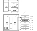
制御装置30は、図示しないCPUやROM,RAM,HDDなどを備える。制御装置30は、図3に示すように機能ブロックとして、各部を駆動する駆動制御部32と、マークカメラ18やパーツカメラ19により撮像された画像を処理する画像処理部34とを備える。駆動制御部32は、フィーダ20のモータ21や基板搬送装置12、ヘッド14、移動機構16、マークカメラ18、パーツカメラ19などへ制御信号を出力する。駆動制御部32には、フィーダ20の制御部からの部品Pに関する各種情報やマークカメラ18からの画像信号、パーツカメラ19からの画像信号などが入力される。マークカメラ18やパーツカメラ19からの画像信号は、画像処理部34で処理される。なお、画像信号が画像処理部34に直接入力されてもよい。また、制御装置30は、実装処理に関する情報の管理を行う管理装置40と通信ネットワークを介して双方向通信可能に接続されており、互いにデータや制御信号のやり取りを行っている。
The
画像処理部34は、識別器記憶部36を備えている。識別器記憶部36は、テープ22のキャビティ24内の部品Pの有無を判定するための複数の識別器38を記憶している。図4は、識別器38の一例を示す説明図である。図示するように、本実施形態では、テープ22の種類であるテープ種と部品Pの種類である部品種と対応付けた複数の識別器38が記憶されている。例えば、テープ種T1と部品種P1とに対応付けられた識別器38(1)やテープ種T1と部品種P2とに対応付けられた識別器38(2)などがある。なお、テープ種T1,T2,T3,・・・としては、例えば白色の紙テープ,黒色のエンボステープ,透明のエンボステープなどが挙げられ、材質や色,透光性などの違いにより画像内での輝度が異なる。また、部品種P1,P2,・・・としては、例えば角チップ部品,バンプ部品,リード部品などが挙げられ、材質や色、形状などの違いにより画像内での輝度が異なる。各識別器38の作成は、例えばマークカメラ18によりテープ22(キャビティ24)の画像を撮像して、管理装置40などのコンピュータに出力し、そのコンピュータの画像処理機能を用いて画像から抽出した特徴量を学習することにより行われる。この特徴量や学習の詳細は後述する。
The
管理装置40は、汎用のコンピュータであり、図3に示すように、管理制御部42と、キーボードやマウスなどの入力デバイス44と、ディスプレイ46と、HDDやSSDなどの記憶部48と、を備える。管理制御部42は、CPUやROM,RAMなどで構成され、入力デバイス44から入力信号を入力し、ディスプレイ46への画像信号を出力する。記憶部48は、基板Sの生産計画を記憶している。基板Sの生産計画は、実装装置10において基板Sの実装面のどの位置にどの部品Pをどの順番で実装するか、部品Pを実装した基板Sを何枚作製するかなどを定めた計画である。管理装置40は、生産計画に従って部品Pが実装されるように制御装置30に指令信号を出力して、実装装置10に実装処理を行わせる。
The
以下は、こうして構成された実装装置10の動作の説明である。ここでは、キャビティ24内の部品有無の判定に関する処理を説明する。先に識別器38を作成する際の学習処理を説明してから、識別器38を用いた部品有無の判定処理を説明する。図5は、特徴量学習処理の一例を示すフローチャートである。この処理は、管理装置40の管理制御部42により実行されるが、他のコンピュータにより実行されてもよい。
The following is a description of the operation of the mounting
この処理では、管理制御部42は、部品Pの有無が既に判明しているキャビティ24をマークカメラ18で撮像した複数の画像Gaを取得する(S100)。S100では、例えば、未使用のテープ22など部品Pが収容されているキャビティ24を撮像した部品有り画像と、全ての部品Pが供給された使用済みのテープ22など部品Pが収容されていないキャビティ24を撮像した部品無し画像とが取得される。また、各部品有り画像は、同じテープ種および同じ部品種を対象として撮像され、各部品無し画像は、部品有り画像と同じテープ種を対象として撮像されたものとする。なお、撮像された画像Gaを順次取得しながら、以下の処理を並行して行ってもよい。
In this process, the
次に、管理制御部42は、1の画像Gaから特徴量の抽出範囲Arを設定し(S105)、設定した抽出範囲Arから各画素の輝度を抽出する(S110)。続いて、管理制御部42は、抽出した画素の輝度に基づいて、最大輝度と最小輝度と平均輝度とコントラストと輝度分散との5つの特徴量を取得する(S115)。コントラストは、例えば最大輝度と最小輝度との比として取得される。輝度分散は、各画素の輝度と平均輝度との偏差の二乗の総和を画素数で除することにより取得される。なお、管理制御部42は、分散に代えて標準偏差を取得してもよい。また、管理制御部42は、今回の画像Gaが部品有り画像であるか否かを判定し(S120)、部品有り画像であると判定すると、S115の各特徴量を部品有りに対応付け(S125)、部品有り画像でなく部品無し画像であると判定すると、S115の各特徴量を部品無しに対応付ける(S130)。
Next, the
ここで、図6は、部品有り画像の一例を示す説明図であり、図7は、部品無し画像の一例を示す説明図であり、図8は、部品の有無と特徴量との関係の一例を示す説明図である。S105で設定される抽出範囲Arは、例えば部品Pの矩形状の上面サイズに対し、縦横のそれぞれの両側にマージンαを加えた範囲とする。マージンαは、一定値でもよいし、部品Pのサイズに比例した値でもよい。また、縦方向と横方向のマージンαは、同じ値に限られず、異なる値でもよい。抽出範囲Arの中心位置は、例えばキャビティ24内の部品Pが吸着ノズル15で吸着される際の中心位置24c(所定の供給位置)と一致するように定められる。これらのことから、部品Pがキャビティ24内で位置ずれしていても、画像内に部品Pの上面とキャビティ24の底面とが含まれることになる。
Here, FIG. 6 is an explanatory diagram showing an example of an image with parts, FIG. 7 is an explanatory diagram showing an example of an image without parts, and FIG. 8 is an example of the relationship between the presence/absence of parts and feature amounts. It is an explanatory view showing . The extraction range Ar set in S105 is, for example, a range obtained by adding a margin α to each of the vertical and horizontal sides of the rectangular upper surface size of the part P. The margin α may be a constant value or a value proportional to the size of the part P. Also, the vertical and horizontal margins α are not limited to the same value, and may be different values. The center position of the extraction range Ar is determined to match the
また、図6では、部品PのボディPbの両端に電極Peが設けられたものを示す。このため、部品有り画像では各部の光の反射の違いにより輝度にばらつきが生じており、例えば、電極Peの輝度が最も高く、次にボディPbの輝度が高く、キャビティ24の底面の輝度が最も低い傾向となる。なお、テープ種や部品種によっては異なる傾向となることもあるが、通常は部品Pの上面とキャビティ24の底面の輝度は異なるため、各画素の輝度にばらつきが生じやすくなる。一方、図7に示すように、部品無し画像ではキャビティ24の底面のみが画像に写るため、各画素の輝度は比較的低い輝度で一様の輝度分布となり、輝度のばらつきが小さな傾向となる。黒色のエンボステープでは、その傾向が顕著となり、白色の紙テープでもその傾向が現れやすい。ただし、透明のエンボステープでは、テープ22の下方にあるフィーダ20の構成部材の反射光を透過し、その構成部材の材質によって輝度が異なることになる。即ち、透明のエンボステープは、黒色のエンボステープや白色の紙テープに比べて外乱の影響により輝度のばらつきが大きくなることがある。
In addition, FIG. 6 shows a component P in which electrodes Pe are provided at both ends of the body Pb. For this reason, in the image with the component, the luminance varies due to the difference in the reflection of light at each part. tend to be low. Although there may be a tendency to differ depending on the type of tape and the type of component, since the brightness of the top surface of the component P and the bottom surface of the
また、図8では、横軸に画像Gaの数(データ数)をとり、縦軸に特徴量の1つである輝度分散をとり、部品有りを黒丸で図示し、部品無しを白丸で図示する。部品有りの場合には部品無しの場合よりも輝度にばらつきが生じやすい傾向にあるため、輝度分散は、部品有りの場合に比較的大きな値となり、部品無しの場合に比較的小さな値となる。また、図8では、部品の有無の違いによる輝度分散の境界が現れており、その境界に基づいて部品の有無を判定するための輝度分散の閾値Srefを定めることができる。 In FIG. 8, the horizontal axis represents the number of images Ga (the number of data), and the vertical axis represents luminance variance, which is one of the feature quantities. . Since luminance tends to vary more easily when there are parts than when there are no parts, the luminance variance is relatively large when there are parts and relatively small when there are no parts. In addition, in FIG. 8, the boundary of the luminance distribution due to the difference in the presence or absence of the component appears, and the threshold value Sref of the luminance distribution for determining the presence or absence of the component can be determined based on the boundary.
特徴量学習処理のS125,S130で部品有無に特徴量を対応付けると、管理制御部42は、全ての画像Gaを処理したか否かを判定し(S135)、未処理の画像Gaがあると判定すると、S105に戻り処理を行う。一方、管理制御部42は、S135で全ての画像Gaを処理したと判定すると、部品有無が対応付けられた特徴量を用いた機械学習により識別器38を作成する(S140)。機械学習は、例えばSVM(サポートベクターマシン)やAdaBoostなどにより、5つの特徴量を部品の有無で分類して識別境界を決定し、その識別境界に基づいて部品有無の判定に用いられる閾値が設定された識別器38を作成する。
When the feature amount is associated with the presence or absence of parts in S125 and S130 of the feature amount learning process, the
そして、管理制御部42は、作成した識別器38をテープ種と部品種に対応付けて識別器記憶部36に記憶させて(S145)、特徴量学習処理を終了する。なお、管理制御部42が、複数の識別器38を記憶部48に記憶しておき、必要な場合に画像処理部34に送信して使用可能とするものなどとしてもよい。
Then, the
次に、キャビティ24内の部品有無の判定処理を説明する。図9は、部品有無判定処理の一例を示すフローチャートである。この処理は、部品有無の判定タイミングとなったときに画像処理部34により実行される。なお、部品有無の判定タイミングは、例えば吸着ノズル15による部品Pの吸着エラーが所定回数続けて発生した場合や、新たなフィーダ20が実装装置10にセットされ部品Pを収容している先頭のキャビティ24までテープ22を送り出す場合などが該当する。
Next, the process of determining the presence/absence of a component inside the
この処理では、画像処理部34は、まずテープ種と部品種とを取得済みであるか否かを判定する(S200)。画像処理部34は、テープ種と部品種とを取得済みでないと判定すると、テープ種を取得すると共に(S205)、部品種を取得する(S210)。なお、S205,S210の処理は、例えば図示しない操作パネルなどにより作業者に入力されたテープ種や部品種を取得することにより行われる。あるいは、フィーダ20の制御部との通信を介して入力されたテープ種や部品種を取得してもよい。また、画像処理部34は、テープ22においてキャビティ24が形成されていない平面部分の画像を撮像し、その画像から取得した画素の輝度と、テープ種毎に予め取得された基準輝度とに基づいてテープ種を判定してもよい。例えば、画像処理部34は、画像から各画素の平均輝度を取得し、平均輝度が基準輝度に最も近いテープ種と判定することができる。
In this process, the
次に、画像処理部34は、キャビティ24をマークカメラ18で撮像した画像Gを取得し(S215)、画像Gから特徴量の抽出範囲Arを設定する(S220)。この抽出範囲Arは、特徴量学習処理のS105と同じ範囲である。続いて、画像処理部34は、設定した抽出範囲Arの画像を切り出して特定サイズに変換し平均化処理することにより正規化する(S225)。図10は画像を正規化する様子の一例を示す説明図である。図示するように、抽出範囲Arの画像が、縦M画素×横N画素の特定サイズの画像に変換される。このため、処理対象の画像サイズを揃えて、画像毎に抽出される画素数を一定とすることができる。また、S225では、ガウシアンフィルタや移動平均フィルタなどのフィルタを用いて平均化処理を行うことにより、ノイズを除去することができる。
Next, the
続いて、画像処理部34は、特定サイズの画像から各画素の輝度を抽出し(S230)、抽出した画素の輝度に基づいて5つの特徴量、即ち最大輝度と最小輝度と平均輝度とコントラストと輝度分散と取得する(S235)。そして、画像処理部34は、S205,S210で取得したテープ種と部品種とに対応する識別器38を用いて、取得した各特徴量を入力して部品有無を判定し(S240)、判定結果を出力して(S245)、部品有無判定処理を終了する。例えば、S205,S210でテープ種T2と部品種P2とが取得された場合、画像処理部34は、識別器38(12)を用いて部品の有無を判定する。
Subsequently, the
また、S245では、部品有無の判定結果が、例えば駆動制御部32や管理装置40などに出力される。駆動制御部32は、部品Pの吸着エラーが所定回数続けて発生した場合に、部品Pが無いと判定されると、次のキャビティ24までテープ22を送るようにフィーダ20を制御し、部品Pが有ると判定されると、部品Pを再吸着するようにヘッド14を制御する。また、駆動制御部32は、新たなフィーダ20が実装装置10にセットされてテープ22を送り出している場合に部品Pが有ると判定されると、テープ22の送り出しを終了させる。また、駆動制御部32は、図示しない操作パネルなどに、部品が無い旨の情報を表示してもよい。また、フィーダ20が実装装置10に対して図示しない交換装置により着脱されるように構成されている場合、管理装置40は、部品Pが無い旨の判定結果を受けて、そのフィーダ20の交換指示を交換装置に出力する。このため、まだ部品Pが有る場合に、交換装置がフィーダ20を交換するのを防止することができる。
Further, in S245, the determination result of the presence/absence of the component is output to the
ここで、本実施形態の構成要素と本開示の構成要素との対応関係を明らかにする。本実施形態の画像処理部34が本開示の画像処理装置に相当し、キャビティ24がキャビティに相当し、テープ22がテープに相当し、部品有無判定処理のS230,S235を実行する画像処理部34が特徴量取得部に相当し、部品有無判定処理のS240を実行する画像処理部34が判定部に相当する。部品有無判定処理のS205を実行する画像処理部34がテープ種取得部に相当する。部品有無判定処理のS210を実行する画像処理部34が部品種取得部に相当する。また、フィーダ20がフィーダに相当し、実装装置10が実装装置に相当し、マークカメラ18が撮像装置に相当する。なお、本実施形態は、画像処理部34の動作を説明することにより本開示の画像処理方法の一例も明らかにしている。
Here, correspondence relationships between the components of the present embodiment and the components of the present disclosure will be clarified. The
以上説明した実装装置10は、画像処理部34が、画像Gから抽出した輝度の特徴量を取得し、キャビティ24内に部品Pが有る場合と部品Pが無い場合のそれぞれの特徴量に基づいて定められた判定用の閾値と、画像Gから取得した特徴量とに基づいて、キャビティ24内の部品Pの有無を判定する。取得される特徴量は、部品種や撮像条件などの違いに拘わらず、キャビティ24内の部品Pの有無の違いによって同じような傾向が現れるから、キャビティ24内の部品Pの有無を精度よく判定することができる。
In the mounting
また、画像処理部34は、抽出範囲Arが部品Pの供給位置を中心として部品Pのサイズにマージンαを加えた範囲に定められており、抽出範囲Arを特定サイズに変換し平均化した画像から画素の輝度を抽出する。このため、輝度を抽出する画素数を一定としてノイズの影響を抑えることができるから、特徴量を安定的に取得して部品Pの有無をより精度よく判定することができる。
Further, the
また、画像処理部34は、処理対象のテープ22の種類を取得し、テープ種に対応する識別器38を用いて部品Pの有無を判定するから、テープ22の材質などの違いによる特徴量の変化の影響を抑えることができる。また、画像処理部34は、処理対象の部品Pの種類を取得し、部品種に対応する識別器38を用いて部品Pの有無を判定するから、部品Pの材質などの違いによる特徴量の変化の影響を抑えることができる。
In addition, since the
また、画像処理部34は、輝度分散と最大輝度と最小輝度と輝度平均とコントラストとの5つの特徴量を取得する。また、5つの特徴量を変数として機械学習により閾値が設定された識別器38と、画像Gから取得された5つの特徴量とに基づいて部品Pの有無を判定するから、判定精度を高めて部品Pの有無を誤判定するのを防止することができる。
In addition, the
また、実装装置10は、画像処理部34が部品Pの有無を精度よく判定するため、キャビティ24内に部品Pが無いのに部品Pの吸着(採取)を繰り返すのを防止したり、部品Pが無くなりテープ22の交換タイミングとなったことを適切に判定することができる。
In addition, since the
なお、本開示は上述した実施形態に何ら限定されることはなく、本開示の技術的範囲に属する限り種々の態様で実施し得ることはいうまでもない。 It goes without saying that the present disclosure is not limited to the above-described embodiments, and can be implemented in various forms as long as they fall within the technical scope of the present disclosure.
例えば、上述した実施形態では、輝度分散を含む5つの特徴量を取得したが、これに限られず、輝度の分散または標準偏差と、輝度の分散または標準偏差以外の輝度に関する値とを含む複数の特徴量を取得すればよい。即ち、輝度の分散または標準偏差を含む2以上の特徴量を取得すればよい。また、輝度のばらつきを示す値として輝度分散を例示したが、コントラストや輝度平均などの他の指標を用いてもよい。 For example, in the above-described embodiment, five feature quantities including brightness variance were acquired, but not limited to this, a plurality of brightness values including variance or standard deviation of brightness and values related to brightness other than variance or standard deviation of brightness What is necessary is just to acquire a feature-value. In other words, two or more feature quantities including luminance variance or standard deviation may be acquired. Also, although the brightness variance has been exemplified as a value indicating the variation in brightness, other indices such as contrast and brightness average may be used.
上述した実施形態では、複数の識別器38がテープ種と部品種の両方に対応付けられていたが、これに限られず、テープ種と部品種のいずれか一方に対応付けられていてもよい。例えば、画像処理部34は、図9のS210の部品種の取得を省略して、部品種に拘わらず、S205で取得したテープ種に対応する識別器38を用いて部品有無を判定してもよい。また、画像処理部34は、図9のS205のテープ種の取得を省略して、テープ種に拘わらず、S210で取得した部品種に対応する識別器38を用いて部品有無を判定してもよい。また、テープ種と部品種のいずれにも対応付けられていない共用の識別器38を用いてもよい。その場合、画像処理部34は、図9のS200~S210の処理を省略すればよい。
In the above-described embodiment, the
また、テープ種や部品種の違いによる誤判定の可能性や判定頻度(使用頻度)などに応じて、必要な識別器38が識別器記憶部36に記憶されていればよい。例えば、透明のエンボステープなど誤判定の可能性が高いテープ種についてはテープ種に対応付けられた識別器38を用いたり、誤判定の可能性が高いテープ種と部品種の組み合わせなどについてはテープ種と部品種とに対応付けられた識別器38を用いたり、誤判定の可能性が低いテープ種や部品種については共用の識別器38を用いたりするものなどとしてもよい。
In addition, the
上述した実施形態では、特徴量学習処理では、画像Gaの抽出範囲Arから画素を抽出したが、これに限られず、抽出範囲Arを特定サイズに正規化した画像から画素を抽出してもよい。また、部品有無判定処理では、抽出範囲Arを特定サイズに正規化した画像から画素を抽出したが、これに限られず、抽出範囲Arから画素を抽出してもよい。 In the above-described embodiment, in the feature amount learning process, pixels are extracted from the extraction range Ar of the image Ga, but the invention is not limited to this, and pixels may be extracted from an image obtained by normalizing the extraction range Ar to a specific size. Also, in the component presence/absence determination process, pixels are extracted from an image obtained by normalizing the extraction range Ar to a specific size, but the invention is not limited to this, and pixels may be extracted from the extraction range Ar.
上述した実施形態では、抽出範囲Arの中心位置は、部品Pが吸着ノズル15で吸着される際の中心位置24cと一致したが、これに限られず、キャビティ24の範囲内で抽出範囲Arが設定されればよい。また、抽出範囲Arは、部品Pのサイズにマージンαを加えた範囲としたが、キャビティ24よりも若干狭い範囲など、部品Pの上面とキャビティ24の底面とが写る範囲であればよい。
In the above-described embodiment, the center position of the extraction range Ar coincides with the
上述した実施形態では、特徴量学習処理が画像処理部34以外の管理制御部42などにより実行されたが、これに限られず、画像処理部34により実行されてもよい。画像処理部34による特徴量学習処理は、実装処理が行われていない場合に実行されればよい。あるいは、実装処理中に、吸着ノズル15で部品Pを吸着する前にマークカメラ18で画像を撮像しておき、部品Pが吸着されれば、その画像を部品有り画像として学習していくものなどとしてもよい。
In the above-described embodiment, the feature amount learning process is executed by the
上述した実施形態では、取得した特徴量を識別器38に入力して部品Pの有無を判定するもの即ち識別器38による判定結果(識別結果)を得るものとしたが、これに限られるものではない。例えば図8のように、輝度分散などの1以上の特徴量と、部品Pの有無とに相関があり閾値Srefを設定可能な場合、取得された特徴量と閾値Srefとを用いて判定してもよい。図8の例では、取得された輝度分散が閾値Sref以上であれば部品Pが有り、輝度分散が閾値Sref未満であれば部品Pが無いと判定されることになる。
In the above-described embodiment, the acquired feature amount is input to the
上述した実施形態では、管理制御部42は、5つの特徴量を部品Pの有無で分類して識別境界を決定し、その識別境界に基づいて部品有無の判定に用いられる閾値が設定された識別器38を作成したが、これに限られるものではない。例えば、管理制御部42は、識別境界自体を用いて部品有無を判定する識別器を作成してもよい。さらに、管理制御部42は、部品有無を判定する識別境界を複数有する識別器を作成してもよい。また、管理制御部42は、複数の特徴量で構成される複数次元の座標系における座標の値に応じて重みづけ係数を設定し、複数の特徴量が重みづけ係数で重みづけされた後の値と、閾値または識別境界との関係により部品有無を判定する識別器を作成してもよい。
In the above-described embodiment, the
上述した実施形態では、実装装置10が備える画像処理部34が部品Pの有無を判定したが、これに限られず、管理装置40の管理制御部42など、実装装置10以外に設けられた画像処理装置が部品Pの有無を判定してもよい。
In the above-described embodiment, the
ここで、本開示の画像処理装置は、以下のように構成してもよい。例えば、本開示の画像処理装置において、前記所定範囲は、前記テープが前記キャビティ内の部品を供給する際の供給位置を中心として、部品のサイズに所定のマージンを加えた範囲に定められており、前記特徴量取得部は、前記画像における前記所定範囲を特定サイズに変換し平均化した画像から前記画素の輝度を抽出するものとしてもよい。こうすれば、特定サイズの画像から輝度を抽出するから、画像毎に輝度を抽出する画素数を一定とすることができる。また、特定サイズに変換して平均化した画像から輝度を抽出するから、ノイズの影響を抑えることができる。したがって、特徴量を安定的に取得して、キャビティ内の部品の有無をより精度よく判定することができる。 Here, the image processing apparatus of the present disclosure may be configured as follows. For example, in the image processing apparatus of the present disclosure, the predetermined range is defined as a range obtained by adding a predetermined margin to the size of the component, centering on the supply position when the tape supplies the component in the cavity. The feature amount acquisition unit may extract the brightness of the pixel from an image obtained by converting the predetermined range in the image into a specific size and averaging the image. By doing so, since the luminance is extracted from an image of a specific size, the number of pixels from which the luminance is extracted can be made constant for each image. In addition, since the brightness is extracted from the averaged image converted to a specific size, the influence of noise can be suppressed. Therefore, it is possible to stably acquire the feature amount and more accurately determine the presence or absence of the component in the cavity.
本開示の画像処理装置において、処理対象の前記テープの種類を取得するテープ種取得部を備え、前記判定部は、前記テープの種類毎に定められた前記判定用の閾値のうち前記テープ種取得部により取得された前記テープの種類に応じた閾値を用いるものとしてもよい。こうすれば、テープの材質などの違いによる特徴量の変化の影響を抑えて、キャビティ内の部品の有無をさらに精度よく判定することができる。 The image processing apparatus according to the present disclosure includes a tape type acquisition unit that acquires the type of the tape to be processed, and the determination unit obtains the tape type from among the determination threshold values determined for each type of tape. A threshold corresponding to the type of the tape acquired by the unit may be used. By doing so, it is possible to suppress the influence of changes in the feature quantity due to the difference in the material of the tape, etc., and to more accurately determine the presence or absence of the component in the cavity.
本開示の画像処理装置において、供給対象の部品の種類を取得する部品種取得部を備え、前記判定部は、前記部品の種類毎に定められた前記判定用の閾値のうち前記部品種取得部により取得された前記部品の種類に応じた閾値を用いるものとしてもよい。こうすれば、部品の材質や形状などの違いによる特徴量の変化の影響を抑えて、キャビティ内の部品の有無をさらに精度よく判定することができる。 The image processing apparatus according to the present disclosure includes a component type acquisition unit that acquires the type of the component to be supplied, and the determination unit selects the component type acquisition unit from among the determination threshold values determined for each type of the component. A threshold may be used according to the type of the part acquired by the method. In this way, the presence or absence of a component in the cavity can be determined more accurately by suppressing the influence of changes in feature amounts due to differences in the material, shape, etc. of the component.
本開示の画像処理装置において、前記特徴量取得部は、輝度のばらつきを示す値として輝度の分散または標準偏差を取得すると共に分散および標準偏差以外の輝度に関する値を含む複数の前記特徴量を取得し、前記判定部は、複数の前記特徴量を変数として機械学習により定められた前記閾値と、前記画像から取得された複数の前記特徴量とに基づいて、前記キャビティ内の部品の有無を判定するものとしてもよい。こうすれば、キャビティ内の部品の有無の判定精度を高めることができるから、部品の有無を誤判定するのを防止することができる。 In the image processing device of the present disclosure, the feature amount acquisition unit acquires luminance variance or standard deviation as a value indicating luminance variation, and acquires a plurality of feature amounts including luminance-related values other than variance and standard deviation. The determining unit determines whether or not there is a part in the cavity based on the threshold determined by machine learning using the plurality of feature amounts as variables and the plurality of feature amounts obtained from the image. It may be assumed that By doing so, it is possible to improve the accuracy of determining the presence or absence of a component in the cavity, thereby preventing erroneous determination of the presence or absence of the component.
本開示の別の画像処理装置は、供給対象の部品を収納するキャビティが複数設けられたテープの画像を処理する画像処理装置であって、前記画像を用いて前記キャビティの底面と該キャビティ内の部品とが含まれうる所定範囲の画素の輝度を抽出し、抽出した輝度のばらつきを示す値を特徴量として取得する特徴量取得部と、前記キャビティ内に部品が有る場合と部品が無い場合のそれぞれの前記特徴量に基づいて作成された判定用の識別器と、前記画像から取得された前記特徴量とに基づいて、前記キャビティ内の部品の有無を判定する判定部と、を備えることを要旨とする。上述したように、画像から取得される特徴量は、キャビティ内の部品の有無の違いによって同じような傾向が現れる。このため、特徴量に基づいて作成された識別器を用いることで、部品種や撮像条件などが変わっても、キャビティ内の部品の有無を精度よく判定することができる。 Another image processing device of the present disclosure is an image processing device that processes an image of a tape provided with a plurality of cavities for storing parts to be supplied, and uses the image to determine the bottom surface of the cavity and the inside of the cavity. a feature amount acquisition unit that extracts the brightness of pixels in a predetermined range that may include a part and acquires a value indicating the variation in the extracted brightness as a feature amount; A discriminator for determination created based on each of the feature amounts, and a determination unit that determines the presence or absence of a component in the cavity based on the feature amount acquired from the image. This is the gist. As described above, the feature quantity obtained from the image shows a similar tendency depending on the presence or absence of the component inside the cavity. Therefore, by using a discriminator created based on the feature amount, it is possible to accurately determine the presence or absence of the component in the cavity even if the component type, imaging conditions, etc. are changed.
本開示の実装装置は、前記テープを送るフィーダが取り付けられ、供給対象の部品を前記キャビティから採取して実装する実装装置であって、前記テープの画像を撮像する撮像装置と、上述したいずれかの画像処理装置と、を備えることを要旨とする。本開示の実装装置は、上述したいずれかの画像処理装置によりキャビティ内の部品の有無を精度よく判定することができる。このため、キャビティ内に部品が無いのに部品の採取を繰り返すのを防止したり、キャビティ内に部品が無くなってテープの交換タイミングとなったことを適切に判定することができる。 A mounting apparatus according to the present disclosure is a mounting apparatus that is attached with a feeder that feeds the tape, picks up and mounts a component to be supplied from the cavity, and includes an imaging device that captures an image of the tape, and any one of the above and an image processing device. The mounting apparatus of the present disclosure can accurately determine the presence/absence of a component inside the cavity by any of the image processing apparatuses described above. Therefore, it is possible to prevent repeated collection of components when there are no components in the cavity, and to appropriately determine when it is time to replace the tape when there are no components in the cavity.
本開示の画像処理方法は、供給対象の部品を収納するキャビティが複数設けられたテープの画像を処理する画像処理方法であって、(a)前記画像を用いて前記キャビティの底面と該キャビティ内の部品とが含まれうる所定範囲の画素の輝度を抽出し、抽出した輝度のばらつきを示す値を特徴量として取得するステップと、(b)前記キャビティ内に部品が有る場合の前記特徴量と前記キャビティ内に部品が無い場合の前記特徴量とに基づいて定められた判定用の閾値と、前記画像から取得された前記特徴量とに基づいて、前記キャビティ内の部品の有無を判定するステップと、を含むことを要旨とする。本開示の画像処理方法では、上述した画像処理装置と同様に、部品種や撮像条件などが変わっても、キャビティ内の部品の有無を精度よく判定することができる。なお、この画像処理方法において、上述した画像処理装置の種々の態様を採用してもよいし、上述した画像処理装置の各機能を実現するようなステップを追加してもよい。 An image processing method of the present disclosure is an image processing method for processing an image of a tape provided with a plurality of cavities for storing parts to be supplied, comprising: (a) using the image, the bottom surface of the cavity and the inside of the cavity; a step of extracting the brightness of pixels in a predetermined range that can include the component and obtaining a value indicating the variation in the extracted brightness as a feature amount; (b) the feature amount when there is a part in the cavity; Determining whether or not there is a part in the cavity based on a determination threshold value determined based on the feature amount when there is no part in the cavity, and the feature amount obtained from the image. and In the image processing method of the present disclosure, similarly to the image processing apparatus described above, it is possible to accurately determine the presence or absence of a component in the cavity even if the component type, imaging conditions, etc. are changed. In this image processing method, various aspects of the above-described image processing apparatus may be adopted, and steps for realizing each function of the above-described image processing apparatus may be added.
本発明は、テープに収容された部品を送る供給装置や供給された部品を実装する実装装置などに利用可能である。 INDUSTRIAL APPLICABILITY The present invention can be used for a supply device that sends components stored on a tape, a mounting device that mounts supplied components, and the like.
10 実装装置、12 基板搬送装置、14 ヘッド、15 吸着ノズル、16 移動機構、18 マークカメラ、19 パーツカメラ、20 フィーダ、21 モータ、22 テープ、23 送り穴、24 キャビティ、24c 中心位置、30 制御装置、32 駆動制御部、34 画像処理部、36 識別器記憶部、38 識別器、40 管理装置、42 管理制御部、44 入力デバイス、46 ディスプレイ、48 記憶部、G 画像、P 部品、Pb ボディ、Pe 電極、S 基板。
10
Claims (8)
前記画像を用いて前記キャビティの底面と該キャビティ内の部品とが含まれうる所定範囲の画素の輝度を抽出し、抽出した輝度のばらつきを示す値を特徴量として取得する特徴量取得部と、
前記キャビティ内に部品が有る場合と部品が無い場合のそれぞれの前記特徴量に基づいて定められた判定用の閾値と、前記画像から取得された前記特徴量とに基づいて、前記キャビティ内の部品の有無を判定する判定部と、
を備える画像処理装置。An image processing device for processing an image of a tape provided with a plurality of cavities for storing parts to be supplied,
a feature amount acquisition unit that uses the image to extract the brightness of pixels in a predetermined range that may include the bottom surface of the cavity and the component in the cavity, and acquires a value indicating variation in the extracted brightness as a feature amount;
Parts in the cavity based on thresholds for determination determined based on the feature amounts when there is a part in the cavity and when there is no part in the cavity, and the feature amount obtained from the image. A determination unit that determines the presence or absence of
An image processing device comprising:
前記所定範囲は、前記テープが前記キャビティ内の部品を供給する際の供給位置を中心として、部品のサイズに所定のマージンを加えた範囲に定められており、
前記特徴量取得部は、前記画像における前記所定範囲を特定サイズに変換し平均化した画像から前記画素の輝度を抽出する
画像処理装置。The image processing device according to claim 1,
The predetermined range is defined as a range obtained by adding a predetermined margin to the size of the component, centering on the supply position when the tape supplies the component in the cavity,
The image processing device, wherein the feature amount acquisition unit extracts the luminance of the pixel from an image obtained by converting the predetermined range in the image into a specific size and averaging the image.
処理対象の前記テープの種類を取得するテープ種取得部を備え、
前記判定部は、前記テープの種類毎に定められた前記判定用の閾値のうち前記テープ種取得部により取得された前記テープの種類に応じた閾値を用いる
画像処理装置。The image processing device according to claim 1 or 2,
A tape type acquisition unit that acquires the type of the tape to be processed,
The image processing apparatus, wherein the determination unit uses a threshold corresponding to the type of the tape acquired by the tape type acquisition unit, among the thresholds for determination determined for each type of the tape.
供給対象の部品の種類を取得する部品種取得部を備え、
前記判定部は、前記部品の種類毎に定められた前記判定用の閾値のうち前記部品種取得部により取得された前記部品の種類に応じた閾値を用いる
画像処理装置。The image processing device according to any one of claims 1 to 3,
a part type acquiring unit for acquiring the type of parts to be supplied;
The image processing apparatus, wherein the determination unit uses a threshold corresponding to the type of the component acquired by the component type acquisition unit, among the thresholds for determination determined for each type of the component.
前記特徴量取得部は、輝度のばらつきを示す値として輝度の分散または標準偏差を取得すると共に分散および標準偏差以外の輝度に関する値を含む複数の前記特徴量を取得し、
前記判定部は、複数の前記特徴量を変数として機械学習により定められた前記閾値と、前記画像から取得された複数の前記特徴量とに基づいて、前記キャビティ内の部品の有無を判定する
画像処理装置。The image processing device according to any one of claims 1 to 4,
The feature quantity acquisition unit acquires a variance or standard deviation of brightness as a value indicating variation in brightness, and acquires a plurality of feature quantities including values related to brightness other than the variance and standard deviation,
The determination unit determines the presence or absence of a component in the cavity based on the threshold determined by machine learning using the plurality of feature amounts as variables and the plurality of feature amounts acquired from the image. processing equipment.
前記画像を用いて前記キャビティの底面と該キャビティ内の部品とが含まれうる所定範囲の画素の輝度を抽出し、抽出した輝度のばらつきを示す値を特徴量として取得する特徴量取得部と、
前記キャビティ内に部品が有る場合と部品が無い場合のそれぞれの前記特徴量に基づいて作成された判定用の識別器と、前記画像から取得された前記特徴量とに基づいて、前記キャビティ内の部品の有無を判定する判定部と、
を備える画像処理装置。An image processing device for processing an image of a tape provided with a plurality of cavities for storing parts to be supplied,
a feature amount acquisition unit that uses the image to extract the brightness of pixels in a predetermined range that may include the bottom surface of the cavity and the component in the cavity, and acquires a value indicating variation in the extracted brightness as a feature amount;
Based on the discriminator for determination created based on the feature amount when there is a part in the cavity and when there is no part in the cavity, and the feature amount obtained from the image, the inside of the cavity a determination unit that determines the presence or absence of a component;
An image processing device comprising:
前記テープの画像を撮像する撮像装置と、
請求項1ないし6のいずれか1項に記載の画像処理装置と、
を備える実装装置。A mounting device having a feeder for feeding the tape attached thereto, and picking up and mounting a component to be supplied from the cavity,
an imaging device that captures an image of the tape;
an image processing apparatus according to any one of claims 1 to 6;
A mounting device comprising a
(a)前記画像を用いて前記キャビティの底面と該キャビティ内の部品とが含まれうる所定範囲の画素の輝度を抽出し、抽出した輝度のばらつきを示す値を特徴量として取得するステップと、
(b)前記キャビティ内に部品が有る場合と部品が無い場合のそれぞれの前記特徴量に基づいて定められた判定用の閾値と、前記画像から取得された前記特徴量とに基づいて、前記キャビティ内の部品の有無を判定するステップと、
を含む画像処理方法。An image processing method for processing an image of a tape provided with a plurality of cavities for storing parts to be supplied,
(a) using the image to extract the brightness of pixels in a predetermined range that may include the bottom surface of the cavity and the component inside the cavity, and acquiring a value indicating the variation in the extracted brightness as a feature quantity;
(b) Based on the threshold value for determination determined based on each of the feature amounts when there is a part in the cavity and when there is no part in the cavity, and the feature amount obtained from the image, the cavity a step of determining the presence or absence of parts in
An image processing method including
Applications Claiming Priority (1)
| Application Number | Priority Date | Filing Date | Title |
|---|---|---|---|
| PCT/JP2020/015873 WO2021205578A1 (en) | 2020-04-08 | 2020-04-08 | Image processing device, mounting device, and image processing method |
Publications (2)
| Publication Number | Publication Date |
|---|---|
| JPWO2021205578A1 JPWO2021205578A1 (en) | 2021-10-14 |
| JP7298017B2 true JP7298017B2 (en) | 2023-06-26 |
Family
ID=78023605
Family Applications (1)
| Application Number | Title | Priority Date | Filing Date |
|---|---|---|---|
| JP2022513778A Active JP7298017B2 (en) | 2020-04-08 | 2020-04-08 | Image processing device, mounting device, and image processing method |
Country Status (5)
| Country | Link |
|---|---|
| US (1) | US20230217636A1 (en) |
| EP (1) | EP4135503A4 (en) |
| JP (1) | JP7298017B2 (en) |
| CN (1) | CN115211245A (en) |
| WO (1) | WO2021205578A1 (en) |
Families Citing this family (4)
| Publication number | Priority date | Publication date | Assignee | Title |
|---|---|---|---|---|
| WO2023100247A1 (en) * | 2021-11-30 | 2023-06-08 | 株式会社Fuji | Inspection device and inspection method |
| JPWO2023195173A1 (en) * | 2022-04-08 | 2023-10-12 | ||
| JPWO2023248281A1 (en) * | 2022-06-20 | 2023-12-28 | ||
| WO2024009410A1 (en) * | 2022-07-05 | 2024-01-11 | 株式会社Fuji | Component presence/absence determination method and image processing system |
Citations (2)
| Publication number | Priority date | Publication date | Assignee | Title |
|---|---|---|---|---|
| JP2016127217A (en) | 2015-01-08 | 2016-07-11 | パナソニックIpマネジメント株式会社 | Electronic component supply device and processing method for component supply tape in electronic component supply device |
| WO2016203628A1 (en) | 2015-06-18 | 2016-12-22 | 富士機械製造株式会社 | Tape cutting processing device and processing method |
Family Cites Families (10)
| Publication number | Priority date | Publication date | Assignee | Title |
|---|---|---|---|---|
| US6903360B2 (en) * | 2002-10-16 | 2005-06-07 | Agilent Technologies, Inc. | Method for detecting missing components at electrical board test using optoelectronic fixture-mounted sensors |
| DE102004011327B3 (en) * | 2004-03-09 | 2005-11-10 | S-Y Systems Technologies Europe Gmbh | Apparatus and method for determining if a component is missing. |
| JP5443894B2 (en) * | 2009-08-21 | 2014-03-19 | Juki株式会社 | Electronic component mounting apparatus and suction position correction method thereof |
| US9292735B2 (en) * | 2011-09-28 | 2016-03-22 | Honda Motor Co., Ltd. | Living body recognizing device |
| JP6021560B2 (en) | 2012-09-28 | 2016-11-09 | Juki株式会社 | Parts inspection method and apparatus |
| JP2017117341A (en) * | 2015-12-25 | 2017-06-29 | 富士通株式会社 | Object detection method, apparatus, and program |
| JP6748714B2 (en) * | 2016-05-31 | 2020-09-02 | 株式会社Fuji | Parts supply system |
| CN110199588B (en) * | 2017-02-07 | 2020-12-29 | 雅马哈发动机株式会社 | Component mounting apparatus |
| JP6773879B2 (en) * | 2017-02-23 | 2020-10-21 | 株式会社Fuji | Component mounting device |
| JP2019036015A (en) * | 2017-08-10 | 2019-03-07 | ヤマハ発動機株式会社 | Surface mounting machine |
-
2020
- 2020-04-08 EP EP20930555.6A patent/EP4135503A4/en active Pending
- 2020-04-08 US US17/995,633 patent/US20230217636A1/en active Pending
- 2020-04-08 JP JP2022513778A patent/JP7298017B2/en active Active
- 2020-04-08 WO PCT/JP2020/015873 patent/WO2021205578A1/en unknown
- 2020-04-08 CN CN202080097703.4A patent/CN115211245A/en active Pending
Patent Citations (2)
| Publication number | Priority date | Publication date | Assignee | Title |
|---|---|---|---|---|
| JP2016127217A (en) | 2015-01-08 | 2016-07-11 | パナソニックIpマネジメント株式会社 | Electronic component supply device and processing method for component supply tape in electronic component supply device |
| WO2016203628A1 (en) | 2015-06-18 | 2016-12-22 | 富士機械製造株式会社 | Tape cutting processing device and processing method |
Also Published As
| Publication number | Publication date |
|---|---|
| EP4135503A4 (en) | 2023-06-07 |
| JPWO2021205578A1 (en) | 2021-10-14 |
| EP4135503A1 (en) | 2023-02-15 |
| CN115211245A (en) | 2022-10-18 |
| US20230217636A1 (en) | 2023-07-06 |
| WO2021205578A1 (en) | 2021-10-14 |
Similar Documents
| Publication | Publication Date | Title |
|---|---|---|
| JP7298017B2 (en) | Image processing device, mounting device, and image processing method | |
| CN111656883B (en) | Learning completion model generation system and method for component image recognition | |
| US11972589B2 (en) | Image processing device, work robot, substrate inspection device, and specimen inspection device | |
| CN115088402B (en) | Component assembling machine | |
| EP3177130B1 (en) | Component data handling device, component data handling method, and component mounting system | |
| EP3328180B1 (en) | Component-mounting machine | |
| US12223687B2 (en) | Image processing device, component mounting system, and image processing method | |
| CN114788436B (en) | Component mounting machine | |
| JP2017130592A (en) | Component data handling device, component data handling method, and component mounting system | |
| US11219150B2 (en) | Work machine and method for determining polarity | |
| CN111727672B (en) | Component mounting machine | |
| JP7423741B2 (en) | Image processing device and image processing method | |
| JP2011086970A (en) | Electronic component mounting device | |
| JP6654071B2 (en) | Component mounting machine and head unit | |
| JP7142169B2 (en) | Image data management device and image data management method | |
| JP2023089800A (en) | Process valuation device | |
| WO2020183734A1 (en) | Quality determination device and quality determination method | |
| JP2009224483A (en) | Method of mounting component and component suction posture decision method | |
| KR20160011471A (en) | Method for inspecting part pickup | |
| CN118176841A (en) | Component inspection method and component inspection device |
Legal Events
| Date | Code | Title | Description |
|---|---|---|---|
| A621 | Written request for application examination |
Free format text: JAPANESE INTERMEDIATE CODE: A621 Effective date: 20220905 |
|
| TRDD | Decision of grant or rejection written | ||
| A01 | Written decision to grant a patent or to grant a registration (utility model) |
Free format text: JAPANESE INTERMEDIATE CODE: A01 Effective date: 20230606 |
|
| A61 | First payment of annual fees (during grant procedure) |
Free format text: JAPANESE INTERMEDIATE CODE: A61 Effective date: 20230614 |
|
| R150 | Certificate of patent or registration of utility model |
Ref document number: 7298017 Country of ref document: JP Free format text: JAPANESE INTERMEDIATE CODE: R150 |