JP7213370B2 - Multi-view display alignment method and system - Google Patents
Multi-view display alignment method and system Download PDFInfo
- Publication number
- JP7213370B2 JP7213370B2 JP2021559072A JP2021559072A JP7213370B2 JP 7213370 B2 JP7213370 B2 JP 7213370B2 JP 2021559072 A JP2021559072 A JP 2021559072A JP 2021559072 A JP2021559072 A JP 2021559072A JP 7213370 B2 JP7213370 B2 JP 7213370B2
- Authority
- JP
- Japan
- Prior art keywords
- view
- light
- backlight
- array
- alignment pattern
- Prior art date
- Legal status (The legal status is an assumption and is not a legal conclusion. Google has not performed a legal analysis and makes no representation as to the accuracy of the status listed.)
- Active
Links
Images


Classifications
-
- G—PHYSICS
- G02—OPTICS
- G02F—OPTICAL DEVICES OR ARRANGEMENTS FOR THE CONTROL OF LIGHT BY MODIFICATION OF THE OPTICAL PROPERTIES OF THE MEDIA OF THE ELEMENTS INVOLVED THEREIN; NON-LINEAR OPTICS; FREQUENCY-CHANGING OF LIGHT; OPTICAL LOGIC ELEMENTS; OPTICAL ANALOGUE/DIGITAL CONVERTERS
- G02F1/00—Devices or arrangements for the control of the intensity, colour, phase, polarisation or direction of light arriving from an independent light source, e.g. switching, gating or modulating; Non-linear optics
- G02F1/01—Devices or arrangements for the control of the intensity, colour, phase, polarisation or direction of light arriving from an independent light source, e.g. switching, gating or modulating; Non-linear optics for the control of the intensity, phase, polarisation or colour
- G02F1/13—Devices or arrangements for the control of the intensity, colour, phase, polarisation or direction of light arriving from an independent light source, e.g. switching, gating or modulating; Non-linear optics for the control of the intensity, phase, polarisation or colour based on liquid crystals, e.g. single liquid crystal display cells
- G02F1/1303—Apparatus specially adapted to the manufacture of LCDs
-
- G—PHYSICS
- G02—OPTICS
- G02F—OPTICAL DEVICES OR ARRANGEMENTS FOR THE CONTROL OF LIGHT BY MODIFICATION OF THE OPTICAL PROPERTIES OF THE MEDIA OF THE ELEMENTS INVOLVED THEREIN; NON-LINEAR OPTICS; FREQUENCY-CHANGING OF LIGHT; OPTICAL LOGIC ELEMENTS; OPTICAL ANALOGUE/DIGITAL CONVERTERS
- G02F1/00—Devices or arrangements for the control of the intensity, colour, phase, polarisation or direction of light arriving from an independent light source, e.g. switching, gating or modulating; Non-linear optics
- G02F1/01—Devices or arrangements for the control of the intensity, colour, phase, polarisation or direction of light arriving from an independent light source, e.g. switching, gating or modulating; Non-linear optics for the control of the intensity, phase, polarisation or colour
- G02F1/13—Devices or arrangements for the control of the intensity, colour, phase, polarisation or direction of light arriving from an independent light source, e.g. switching, gating or modulating; Non-linear optics for the control of the intensity, phase, polarisation or colour based on liquid crystals, e.g. single liquid crystal display cells
- G02F1/133—Constructional arrangements; Operation of liquid crystal cells; Circuit arrangements
- G02F1/1333—Constructional arrangements; Manufacturing methods
- G02F1/133308—Support structures for LCD panels, e.g. frames or bezels
-
- G—PHYSICS
- G02—OPTICS
- G02B—OPTICAL ELEMENTS, SYSTEMS OR APPARATUS
- G02B6/00—Light guides; Structural details of arrangements comprising light guides and other optical elements, e.g. couplings
- G02B6/0001—Light guides; Structural details of arrangements comprising light guides and other optical elements, e.g. couplings specially adapted for lighting devices or systems
- G02B6/0011—Light guides; Structural details of arrangements comprising light guides and other optical elements, e.g. couplings specially adapted for lighting devices or systems the light guides being planar or of plate-like form
- G02B6/0081—Mechanical or electrical aspects of the light guide and light source in the lighting device peculiar to the adaptation to planar light guides, e.g. concerning packaging
- G02B6/0086—Positioning aspects
-
- G—PHYSICS
- G02—OPTICS
- G02B—OPTICAL ELEMENTS, SYSTEMS OR APPARATUS
- G02B30/00—Optical systems or apparatus for producing three-dimensional [3D] effects, e.g. stereoscopic images
- G02B30/20—Optical systems or apparatus for producing three-dimensional [3D] effects, e.g. stereoscopic images by providing first and second parallax images to an observer's left and right eyes
- G02B30/26—Optical systems or apparatus for producing three-dimensional [3D] effects, e.g. stereoscopic images by providing first and second parallax images to an observer's left and right eyes of the autostereoscopic type
- G02B30/33—Optical systems or apparatus for producing three-dimensional [3D] effects, e.g. stereoscopic images by providing first and second parallax images to an observer's left and right eyes of the autostereoscopic type involving directional light or back-light sources
-
- G—PHYSICS
- G02—OPTICS
- G02F—OPTICAL DEVICES OR ARRANGEMENTS FOR THE CONTROL OF LIGHT BY MODIFICATION OF THE OPTICAL PROPERTIES OF THE MEDIA OF THE ELEMENTS INVOLVED THEREIN; NON-LINEAR OPTICS; FREQUENCY-CHANGING OF LIGHT; OPTICAL LOGIC ELEMENTS; OPTICAL ANALOGUE/DIGITAL CONVERTERS
- G02F1/00—Devices or arrangements for the control of the intensity, colour, phase, polarisation or direction of light arriving from an independent light source, e.g. switching, gating or modulating; Non-linear optics
- G02F1/01—Devices or arrangements for the control of the intensity, colour, phase, polarisation or direction of light arriving from an independent light source, e.g. switching, gating or modulating; Non-linear optics for the control of the intensity, phase, polarisation or colour
- G02F1/13—Devices or arrangements for the control of the intensity, colour, phase, polarisation or direction of light arriving from an independent light source, e.g. switching, gating or modulating; Non-linear optics for the control of the intensity, phase, polarisation or colour based on liquid crystals, e.g. single liquid crystal display cells
- G02F1/133—Constructional arrangements; Operation of liquid crystal cells; Circuit arrangements
- G02F1/1333—Constructional arrangements; Manufacturing methods
- G02F1/133354—Arrangements for aligning or assembling substrates
-
- G—PHYSICS
- G02—OPTICS
- G02F—OPTICAL DEVICES OR ARRANGEMENTS FOR THE CONTROL OF LIGHT BY MODIFICATION OF THE OPTICAL PROPERTIES OF THE MEDIA OF THE ELEMENTS INVOLVED THEREIN; NON-LINEAR OPTICS; FREQUENCY-CHANGING OF LIGHT; OPTICAL LOGIC ELEMENTS; OPTICAL ANALOGUE/DIGITAL CONVERTERS
- G02F1/00—Devices or arrangements for the control of the intensity, colour, phase, polarisation or direction of light arriving from an independent light source, e.g. switching, gating or modulating; Non-linear optics
- G02F1/01—Devices or arrangements for the control of the intensity, colour, phase, polarisation or direction of light arriving from an independent light source, e.g. switching, gating or modulating; Non-linear optics for the control of the intensity, phase, polarisation or colour
- G02F1/13—Devices or arrangements for the control of the intensity, colour, phase, polarisation or direction of light arriving from an independent light source, e.g. switching, gating or modulating; Non-linear optics for the control of the intensity, phase, polarisation or colour based on liquid crystals, e.g. single liquid crystal display cells
- G02F1/133—Constructional arrangements; Operation of liquid crystal cells; Circuit arrangements
- G02F1/1333—Constructional arrangements; Manufacturing methods
- G02F1/1335—Structural association of cells with optical devices, e.g. polarisers or reflectors
- G02F1/1336—Illuminating devices
- G02F1/133602—Direct backlight
- G02F1/133604—Direct backlight with lamps
-
- G—PHYSICS
- G02—OPTICS
- G02F—OPTICAL DEVICES OR ARRANGEMENTS FOR THE CONTROL OF LIGHT BY MODIFICATION OF THE OPTICAL PROPERTIES OF THE MEDIA OF THE ELEMENTS INVOLVED THEREIN; NON-LINEAR OPTICS; FREQUENCY-CHANGING OF LIGHT; OPTICAL LOGIC ELEMENTS; OPTICAL ANALOGUE/DIGITAL CONVERTERS
- G02F1/00—Devices or arrangements for the control of the intensity, colour, phase, polarisation or direction of light arriving from an independent light source, e.g. switching, gating or modulating; Non-linear optics
- G02F1/01—Devices or arrangements for the control of the intensity, colour, phase, polarisation or direction of light arriving from an independent light source, e.g. switching, gating or modulating; Non-linear optics for the control of the intensity, phase, polarisation or colour
- G02F1/13—Devices or arrangements for the control of the intensity, colour, phase, polarisation or direction of light arriving from an independent light source, e.g. switching, gating or modulating; Non-linear optics for the control of the intensity, phase, polarisation or colour based on liquid crystals, e.g. single liquid crystal display cells
- G02F1/133—Constructional arrangements; Operation of liquid crystal cells; Circuit arrangements
- G02F1/1333—Constructional arrangements; Manufacturing methods
- G02F1/1335—Structural association of cells with optical devices, e.g. polarisers or reflectors
- G02F1/1336—Illuminating devices
- G02F1/133602—Direct backlight
- G02F1/133606—Direct backlight including a specially adapted diffusing, scattering or light controlling members
- G02F1/133607—Direct backlight including a specially adapted diffusing, scattering or light controlling members the light controlling member including light directing or refracting elements, e.g. prisms or lenses
-
- G—PHYSICS
- G02—OPTICS
- G02F—OPTICAL DEVICES OR ARRANGEMENTS FOR THE CONTROL OF LIGHT BY MODIFICATION OF THE OPTICAL PROPERTIES OF THE MEDIA OF THE ELEMENTS INVOLVED THEREIN; NON-LINEAR OPTICS; FREQUENCY-CHANGING OF LIGHT; OPTICAL LOGIC ELEMENTS; OPTICAL ANALOGUE/DIGITAL CONVERTERS
- G02F1/00—Devices or arrangements for the control of the intensity, colour, phase, polarisation or direction of light arriving from an independent light source, e.g. switching, gating or modulating; Non-linear optics
- G02F1/01—Devices or arrangements for the control of the intensity, colour, phase, polarisation or direction of light arriving from an independent light source, e.g. switching, gating or modulating; Non-linear optics for the control of the intensity, phase, polarisation or colour
- G02F1/13—Devices or arrangements for the control of the intensity, colour, phase, polarisation or direction of light arriving from an independent light source, e.g. switching, gating or modulating; Non-linear optics for the control of the intensity, phase, polarisation or colour based on liquid crystals, e.g. single liquid crystal display cells
- G02F1/133—Constructional arrangements; Operation of liquid crystal cells; Circuit arrangements
- G02F1/1333—Constructional arrangements; Manufacturing methods
- G02F1/1335—Structural association of cells with optical devices, e.g. polarisers or reflectors
- G02F1/1336—Illuminating devices
- G02F1/133602—Direct backlight
- G02F1/133608—Direct backlight including particular frames or supporting means
-
- G—PHYSICS
- G06—COMPUTING OR CALCULATING; COUNTING
- G06V—IMAGE OR VIDEO RECOGNITION OR UNDERSTANDING
- G06V10/00—Arrangements for image or video recognition or understanding
- G06V10/98—Detection or correction of errors, e.g. by rescanning the pattern or by human intervention; Evaluation of the quality of the acquired patterns
-
- H—ELECTRICITY
- H04—ELECTRIC COMMUNICATION TECHNIQUE
- H04N—PICTORIAL COMMUNICATION, e.g. TELEVISION
- H04N13/00—Stereoscopic video systems; Multi-view video systems; Details thereof
- H04N13/30—Image reproducers
- H04N13/302—Image reproducers for viewing without the aid of special glasses, i.e. using autostereoscopic displays
- H04N13/31—Image reproducers for viewing without the aid of special glasses, i.e. using autostereoscopic displays using parallax barriers
-
- H—ELECTRICITY
- H04—ELECTRIC COMMUNICATION TECHNIQUE
- H04N—PICTORIAL COMMUNICATION, e.g. TELEVISION
- H04N13/00—Stereoscopic video systems; Multi-view video systems; Details thereof
- H04N13/30—Image reproducers
- H04N13/302—Image reproducers for viewing without the aid of special glasses, i.e. using autostereoscopic displays
- H04N13/32—Image reproducers for viewing without the aid of special glasses, i.e. using autostereoscopic displays using arrays of controllable light sources; using moving apertures or moving light sources
-
- H—ELECTRICITY
- H04—ELECTRIC COMMUNICATION TECHNIQUE
- H04N—PICTORIAL COMMUNICATION, e.g. TELEVISION
- H04N13/00—Stereoscopic video systems; Multi-view video systems; Details thereof
- H04N13/30—Image reproducers
- H04N13/349—Multi-view displays for displaying three or more geometrical viewpoints without viewer tracking
- H04N13/351—Multi-view displays for displaying three or more geometrical viewpoints without viewer tracking for displaying simultaneously
-
- H—ELECTRICITY
- H04—ELECTRIC COMMUNICATION TECHNIQUE
- H04N—PICTORIAL COMMUNICATION, e.g. TELEVISION
- H04N13/00—Stereoscopic video systems; Multi-view video systems; Details thereof
- H04N13/30—Image reproducers
- H04N13/398—Synchronisation thereof; Control thereof
-
- G—PHYSICS
- G02—OPTICS
- G02B—OPTICAL ELEMENTS, SYSTEMS OR APPARATUS
- G02B6/00—Light guides; Structural details of arrangements comprising light guides and other optical elements, e.g. couplings
- G02B6/0001—Light guides; Structural details of arrangements comprising light guides and other optical elements, e.g. couplings specially adapted for lighting devices or systems
- G02B6/0011—Light guides; Structural details of arrangements comprising light guides and other optical elements, e.g. couplings specially adapted for lighting devices or systems the light guides being planar or of plate-like form
- G02B6/0033—Means for improving the coupling-out of light from the light guide
- G02B6/005—Means for improving the coupling-out of light from the light guide provided by one optical element, or plurality thereof, placed on the light output side of the light guide
-
- H—ELECTRICITY
- H04—ELECTRIC COMMUNICATION TECHNIQUE
- H04N—PICTORIAL COMMUNICATION, e.g. TELEVISION
- H04N13/00—Stereoscopic video systems; Multi-view video systems; Details thereof
- H04N13/30—Image reproducers
- H04N13/327—Calibration thereof
Landscapes
- Physics & Mathematics (AREA)
- Nonlinear Science (AREA)
- General Physics & Mathematics (AREA)
- Optics & Photonics (AREA)
- Engineering & Computer Science (AREA)
- Crystallography & Structural Chemistry (AREA)
- Chemical & Material Sciences (AREA)
- Mathematical Physics (AREA)
- Multimedia (AREA)
- Signal Processing (AREA)
- Quality & Reliability (AREA)
- Theoretical Computer Science (AREA)
- Manufacturing & Machinery (AREA)
- Planar Illumination Modules (AREA)
- Liquid Crystal (AREA)
- Electrochromic Elements, Electrophoresis, Or Variable Reflection Or Absorption Elements (AREA)
- Devices For Indicating Variable Information By Combining Individual Elements (AREA)
Description
関連出願の相互参照
本出願は、2019年4月2日に出願された米国仮特許出願第62/828,398号の優先権を主張し、その全体は参照によって本明細書中に引用するものとする。
CROSS-REFERENCE TO RELATED APPLICATIONS This application claims priority to U.S. Provisional Patent Application No. 62/828,398, filed April 2, 2019, the entirety of which is hereby incorporated by reference. and
連邦政府資金による研究開発の記載
適用なし
FEDERALLY SPONSORED RESEARCH AND DEVELOPMENT STATEMENT Not applicable
電子ディスプレイは、ユーザに多種多様なデバイス及び製品の情報を伝達するためのほぼユビキタスな媒体である。最も一般的に採用されている電子ディスプレイには、陰極線管(CRT)、プラズマ・ディスプレイ・パネル(PDP)、液晶ディスプレイ(LCD)、エレクトロルミネセンスディスプレイ(EL)、有機発光ダイオード(OLED)及びアクティブマトリクスOLED(AMOLED)ディスプレイ、電気泳動ディスプレイ(EP)、並びに電気機械的又は電気流体的な光変調(例えば、デジタル・マイクロミラー・デバイス、エレクトロウェッティング・ディスプレイなど)を採用する様々なディスプレイが含まれる。一般に、電子ディスプレイは、アクティブディスプレイ(すなわち、光を放射するディスプレイ)又はパッシブディスプレイ(すなわち、他の光源から供給される光を変調するディスプレイ)のいずれかに分類され得る。アクティブディスプレイの最も明らかな例は、CRT、PDP及びOLED/AMOLEDである。放射光を考慮したときに典型的にパッシブとして分類されるディスプレイは、LCD及びEPディスプレイである。パッシブディスプレイは、本来的に低消費電力を含むがこれに限定されない魅力的な性能特性を示すことが多いが、発光能力がないことを考慮すると、多くの実用的な応用において用途が幾分限られることもある。 Electronic displays are a nearly ubiquitous medium for conveying information to users for a wide variety of devices and products. The most commonly employed electronic displays include cathode ray tubes (CRT), plasma display panels (PDP), liquid crystal displays (LCD), electroluminescent displays (EL), organic light emitting diodes (OLED) and active Matrix OLED (AMOLED) displays, electrophoretic displays (EP), and various displays employing electromechanical or electrofluidic light modulation (e.g., digital micromirror devices, electrowetting displays, etc.). be In general, electronic displays can be classified as either active displays (ie, displays that emit light) or passive displays (ie, displays that modulate light provided by other light sources). The most obvious examples of active displays are CRT, PDP and OLED/AMOLED. Displays that are typically classified as passive when considering emitted light are LCD and EP displays. While passive displays often exhibit inherently attractive performance characteristics, including but not limited to low power consumption, their lack of light-emitting capability makes them somewhat of limited utility in many practical applications. Sometimes it is done.
このようなディスプレイのコンポーネントを製造中に位置合わせするための現在の技術としては、組み立て中に顕微鏡を利用して光生成部(例えば、バックライト、フィルムなど)上のマークをディスプレイパネル上のマークと位置合わせして、コンポーネントを適切に位置合わせすることを含むことが多い。しかしながら、こうした技術の欠点には、工具に非常に高い精度が要求されること(例えば、顕微鏡ステージの所与のサイズ、テレセントリックレンズの機械的公差のタイトネスなど)、位置合わせ作業が顕微鏡の視野に制約されること、及びマーク間の局所歪みなどの特定の位置ずれが検出できないことが含まれる。 Current techniques for aligning the components of such displays during manufacture utilize a microscope to align marks on the light generating portion (e.g., backlight, film, etc.) on the display panel during assembly. aligning to properly align the components. However, the drawbacks of such techniques include the very high precision requirements of the tools (e.g. given size of the microscope stage, the tightness of the mechanical tolerances of the telecentric lens, etc.) Constraints and the inability to detect certain misalignments such as local distortions between marks.
本開示は、以下の[1]から[22]を含む。
[1]マルチビューディスプレイの光バルブアレイとマルチビューバックライトを位置合わせする方法であって、上記方法が、
互いに離隔したユニットセルを有するアライメントパターンを上記光バルブアレイ上に確立するステップであって、上記アライメントパターンの各ユニットセルが上記マルチビューディスプレイの異なるビューに対応する異なるビュー方向を有する複数のビューブロックを備えるステップと、
上記アライメントパターンを表示するために上記マルチビューバックライトを使用して上記光バルブアレイを照明するステップと、
上記表示されたアライメントパターン内の上記ユニットセルの誤差尺度を最小化するために、上記マルチビューバックライトと上記光バルブアレイの相対位置を調整するステップとを含み、
各ユニットセル内のビューブロックの配置が上記マルチビューディスプレイのビューの配置に対応する、マルチビューバックライトを位置合わせする方法。
[2]上記マルチビューディスプレイのビューの上記配置が順次配置されたビューの一次元アレイを含み、上記アライメントパターンの各ユニットセルが順次配置されたビューブロックの対応する一次元アレイを有する、上記[1]に記載のマルチビューバックライトを位置合わせする方法。
[3]上記マルチビューディスプレイのビューの配置がビューの二次元アレイを含み、上記アライメントパターンの各ユニットセルがビューブロックの対応する二次元アレイを有する、上記[1]に記載のマルチビューバックライトを位置合わせする方法。
[4]ビューの上記二次元アレイが2行2列に配置された4つのビューの2×2アレイである、上記[3]に記載のマルチビューバックライトを位置合わせする方法。
[5]上記マルチビューバックライトが、
導波光として光を導くように構成された光ガイドと、
上記光ガイドにわたり互いに離隔したマルチビーム要素のアレイであって、上記マルチビーム要素アレイの各マルチビーム要素が、上記光バルブアレイを照明するために、上記異なるビュー方向に対応する方向を有する複数の指向性光ビームとして上記光ガイドからの上記導波光の一部を散乱させるように構成されたマルチビーム要素のアレイとを備え、
各マルチビーム要素のサイズが、上記光バルブアレイの光バルブのサイズの1/4~2倍である、上記[1]に記載のマルチビューバックライトを位置合わせする方法。
[6]上記マルチビーム要素アレイのマルチビーム要素が、上記導波光を回折的に散乱させるように構成された回折格子、上記導波光を反射的に散乱させるように構成されたマイクロ反射要素、及び上記導波光を屈折的に散乱させるように構成されたマイクロ屈折要素のうちの1つ又は複数を備える、上記[5]に記載のマルチビューバックライトを位置合わせする方法。
[7]相対位置を調整するステップが、上記光バルブアレイに対して上記マルチビューバックライトを回転させるステップ、及び上記光バルブアレイに対して上記マルチビューバックライトを並進させるステップの一方又は両方を含む、上記[1]に記載のマルチビューバックライトを位置合わせする方法。
[8]上記誤差尺度が、上記アライメントパターンの上記ユニットセルのそれぞれの間の相対輝度差を含む、上記[1]に記載のマルチビューバックライトを位置合わせする方法。
[9]上記相対輝度差が、上記アライメントパターンの上記ユニットセルのそれぞれの対応するビューブロック間の輝度の差を含む、上記[8]に記載のマルチビューバックライトを位置合わせする方法。
[10]誤差尺度を最小化するために相対位置を調整するステップが、上記ユニットセルの目標位置に対する、上記表示されたアライメントパターン内のユニットセル輝度重心の位置ずれを最小化するステップを含む、上記[1]に記載のマルチビューバックライトを位置合わせする方法。
[11]上記ユニットセル輝度重心の位置ずれを最小化するステップが、上記表示されたアライメントパターン内の個々のユニットセル輝度重心の観察位置と上記個々のユニットセルの対応する目標位置との二乗差の和を最小化するステップを含む、上記[10]に記載のマルチビューバックライトを位置合わせする方法。
[12]マルチビューディスプレイバックライト位置合わせシステムであって、
光バルブのアレイとマルチビューバックライトとを有するマルチビューディスプレイであって、上記光バルブアレイが、上記マルチビューバックライトによって照射されたときに複数のユニットセルを含む表示されたアライメントパターンを生成するように構成されているマルチビューディスプレイと、
上記光バルブアレイと上記マルチビューバックライトの相対位置を調整して、上記表示されたアライメントパターン内の上記ユニットセルの誤差尺度を最小化するように構成された位置決めステージとを備え、
上記複数のユニットセルのユニットセルが互いに離隔しており、各ユニットセルが、上記マルチビューディスプレイの異なるビューに対応する異なるビュー方向を有し、かつ上記異なるビューの配置に対応する配置を有する複数のビューブロックを備える、マルチビューディスプレイバックライト位置合わせシステム。
[13]上記マルチビューディスプレイ上に設けられた上記表示されたアライメントパターンの画像を撮像するように構成されたカメラをさらに備え、上記誤差尺度が、上記表示されたアライメントパターンの上記撮像された画像から決定される、上記[12]に記載のマルチビューディスプレイバックライト位置合わせシステム。
[14]上記マルチビューバックライトが、
導波光として光を導くように構成された光ガイドと、
上記光ガイドにわたり互いに離隔したマルチビーム要素のアレイであって、上記マルチビーム要素アレイの各マルチビーム要素が、上記異なるビュー方向に対応する方向を有する指向性光ビームとして上記光ガイドからの上記導波光の一部を散乱させるように構成されたマルチビーム要素のアレイとを備え、
各マルチビーム要素のサイズが、上記光バルブアレイの光バルブのサイズの1/4~2倍である、上記[12]に記載のマルチビューディスプレイバックライト位置合わせシステム。
[15]上記位置決めステージが、上記マルチビューバックライトと上記光バルブアレイの相対回転及び相対並進の一方又は両方をもたらすように構成されたモータ駆動ステージを備える、上記[12]に記載のマルチビューディスプレイバックライト位置合わせシステム。
[16]上記誤差尺度が、上記表示されたアライメントパターンの上記ユニットセルのそれぞれの間の相対輝度差を含む、上記[12]に記載のマルチビューディスプレイバックライト位置合わせシステム。
[17]上記誤差尺度が、上記ユニットセルの目標位置に対する、上記表示されたアライメントパターン内のユニットセル輝度重心の位置ずれを含む、上記[12]に記載のマルチビューディスプレイバックライト位置合わせシステム。
[18]上記誤差尺度を最小化するステップは、上記位置決めステージを使用して上記光バルブアレイと上記マルチビューバックライトの上記相対位置を調整することによって、上記表示されたアライメントパターン内の個々のユニットセルの輝度重心の観察位置と上記個々のユニットセルの対応する目標位置との間の平方差の和を最小化するステップを含む、上記[17]に記載のマルチビューディスプレイバックライト位置合わせシステム。
[19]自動化マルチビューディスプレイバックライト位置合わせシステムであって、
マルチビューディスプレイであって、上記マルチビューディスプレイのマルチビューバックライトによって照明されると、表示されたアライメントパターンを生成するように構成された光バルブのアレイを有するマルチビューディスプレイと、
上記光バルブアレイと上記マルチビューバックライトの相対位置を調整するように構成されたモータ駆動位置決めステージと、
上記モータ駆動位置決めステージを駆動して、上記表示されたアライメントパターン内の離隔したユニットセルの誤差尺度を最小化するように構成されたフィードバックコントローラとを備え、
上記アライメントパターンが複数の上記離隔したユニットセルを備え、上記離隔したユニットセルのそれぞれが、上記マルチビューディスプレイの異なるビューに対応する異なるビュー方向を有し、かつ上記異なるビューの配置に対応する配置を有する複数のビューブロックを備える、自動化マルチビューディスプレイバックライト位置合わせシステム。
[20]上記マルチビューディスプレイ上に設けられた上記表示されたアライメントパターンの画像を撮像するように構成されたカメラをさらに備え、上記フィードバックコントローラが、上記カメラによって供給された上記表示されたアライメントパターンの上記撮像された画像の上記誤差尺度を決定するように構成される、上記[19]に記載の自動化マルチビューディスプレイバックライト位置合わせシステム。
[21]上記誤差尺度が、上記アライメントパターンの上記ユニットセルのそれぞれの間の相対輝度差、及び上記ユニットセルの目標位置に対する上記表示されたアライメントパターン内のユニットセル輝度重心の位置ずれの一方又は両方を含む、上記[19]に記載の自動化マルチビューディスプレイバックライト位置合わせシステム。
[22]上記マルチビューバックライトが、
導波光として光を導くように構成された光ガイドと、
上記光ガイドにわたり互いに離隔したマルチビーム要素のアレイであって、上記マルチビーム要素アレイの各マルチビーム要素が、上記異なるビュー方向に対応する方向を有する複数の指向性光ビームとして上記光ガイドからの上記導波光の一部を散乱させるように構成されたマルチビーム要素のアレイとを含み、
各マルチビーム要素のサイズが、上記光バルブアレイの光バルブのサイズの1/4~2倍であり、
上記マルチビーム要素アレイのマルチビーム要素が、上記導波光を回折的に散乱させるように構成された回折格子、上記導波光を反射的に散乱させるように構成されたマイクロ反射要素、及び上記導波光を屈折的に散乱させるように構成されたマイクロ屈折要素のうちの1つ又は複数を備える、上記[19]に記載の自動化マルチビューディスプレイバックライト位置合わせシステム。
本明細書に記載の原理による例及び実施形態の様々な特徴は、添付の図面と併せて以下の詳細な説明を参照することによってより容易に理解することができ、これらの図面と詳細な説明において、同様の参照番号は同様の構造要素を示す。
The present disclosure includes the following [1] to [22].
[1] A method of aligning a light valve array and a multi-view backlight of a multi-view display, the method comprising:
establishing an alignment pattern on the light valve array having unit cells spaced apart from each other, wherein each unit cell of the alignment pattern has a plurality of view blocks with different view directions corresponding to different views of the multi-view display. a step comprising
illuminating the light valve array using the multi-view backlight to display the alignment pattern;
adjusting the relative positions of the multi-view backlight and the light valve array to minimize an error measure of the unit cells in the displayed alignment pattern;
A method of aligning a multi-view backlight, wherein the arrangement of view blocks within each unit cell corresponds to the arrangement of views of said multi-view display.
[2] wherein the arrangement of views of the multi-view display comprises a sequentially arranged one-dimensional array of views, each unit cell of the alignment pattern having a corresponding one-dimensional array of sequentially arranged view blocks; 1].
[3] The multi-view backlight of [1] above, wherein the arrangement of views of the multi-view display comprises a two-dimensional array of views, and each unit cell of the alignment pattern has a corresponding two-dimensional array of view blocks. how to align
[4] The method of aligning a multi-view backlight according to [3] above, wherein the two-dimensional array of views is a 2x2 array of four views arranged in two rows and two columns.
[5] The multi-view backlight is
a light guide configured to guide light as guided light;
an array of multibeam elements spaced apart across the light guide, each multibeam element of the multibeam element array having a direction corresponding to the different view directions for illuminating the light valve array. an array of multi-beam elements configured to scatter a portion of the guided light from the light guide as a directional light beam;
The method of aligning a multi-view backlight according to [1] above, wherein the size of each multi-beam element is 1/4 to 2 times the size of the light valves of the light valve array.
[6] a diffraction grating, wherein the multi-beam elements of the multi-beam element array are configured to diffractively scatter the guided light; micro-reflective elements configured to reflectively scatter the guided light; 6. The method of aligning a multi-view backlight of
[7] adjusting the relative position comprises one or both of rotating the multi-view backlight with respect to the light valve array and translating the multi-view backlight with respect to the light valve array; A method of aligning a multi-view backlight according to [1] above, comprising:
[8] The method of aligning a multi-view backlight of [1] above, wherein the error measure comprises a relative luminance difference between each of the unit cells of the alignment pattern.
[9] The method of aligning a multi-view backlight of [8] above, wherein the relative luminance difference comprises a luminance difference between corresponding view blocks of each of the unit cells of the alignment pattern.
[10] adjusting the relative positions to minimize an error measure includes minimizing misalignment of unit cell luminance centroids in the displayed alignment pattern with respect to target positions of the unit cells; A method for aligning a multi-view backlight according to [1] above.
[11] The step of minimizing the positional deviation of the unit cell luminance centroids comprises: The method of aligning a multi-view backlight according to [10] above, comprising minimizing the sum of .
[12] A multi-view display backlight alignment system comprising:
A multi-view display having an array of light valves and a multi-view backlight, wherein the light valve array produces a displayed alignment pattern comprising a plurality of unit cells when illuminated by the multi-view backlight. a multi-view display configured as
a positioning stage configured to adjust the relative positions of the light valve array and the multi-view backlight to minimize an error measure of the unit cells in the displayed alignment pattern;
unit cells of the plurality of unit cells are separated from each other, each unit cell having a different view direction corresponding to a different view of the multi-view display, and having an arrangement corresponding to the arrangement of the different views; A multi-view display backlight alignment system comprising a view block of .
[13] further comprising a camera configured to capture an image of the displayed alignment pattern provided on the multi-view display, wherein the error measure is the captured image of the displayed alignment pattern; The multi-view display backlight alignment system of [12] above, wherein the multi-view display backlight alignment system is determined from:
[14] The multi-view backlight is
a light guide configured to guide light as guided light;
an array of multibeam elements spaced apart across the light guide, each multibeam element of the multibeam element array directing the light guide from the light guide as a directional light beam having a direction corresponding to the different view direction. an array of multibeam elements configured to scatter a portion of the wave light;
The multi-view display backlight alignment system of [12] above, wherein the size of each multi-beam element is 1/4 to 2 times the size of the light valves of the light valve array.
[15] The multi-view of [12] above, wherein the positioning stage comprises a motorized stage configured to provide one or both of relative rotation and translation of the multi-view backlight and the light valve array. Display backlight alignment system.
[16] The multi-view display backlight alignment system of [12] above, wherein the error measure comprises a relative luminance difference between each of the unit cells of the displayed alignment pattern.
[17] The multi-view display backlight alignment system of [12] above, wherein the error measure comprises misalignment of unit cell luminance centroids in the displayed alignment pattern relative to target positions of the unit cells.
[18] Minimizing the error measure includes adjusting the relative positions of the light valve array and the multi-view backlight using the positioning stage to adjust the relative position of each individual within the displayed alignment pattern. The multi-view display backlight alignment system of [17] above, comprising minimizing a sum of squared differences between observed positions of luminance centroids of unit cells and corresponding target positions of said individual unit cells. .
[19] An automated multi-view display backlight alignment system comprising:
a multi-view display having an array of light valves configured to produce a displayed alignment pattern when illuminated by a multi-view backlight of the multi-view display;
a motorized positioning stage configured to adjust the relative positions of the light valve array and the multi-view backlight;
a feedback controller configured to drive the motorized positioning stage to minimize an error measure for spaced unit cells in the displayed alignment pattern;
The alignment pattern comprises a plurality of the spaced unit cells, each spaced unit cell having a different view direction corresponding to a different view of the multi-view display, and an arrangement corresponding to the arrangement of the different views. An automated multi-view display backlight alignment system comprising a plurality of view blocks having
[20] further comprising a camera configured to capture an image of the displayed alignment pattern provided on the multi-view display, wherein the feedback controller detects the displayed alignment pattern provided by the camera; The automated multi-view display backlight alignment system of [19] above, configured to determine the error measure of the captured image of.
[21] wherein the error measure is one of a relative luminance difference between each of the unit cells of the alignment pattern and a misalignment of unit cell luminance centroids in the displayed alignment pattern with respect to target positions of the unit cells; The automated multi-view display backlight alignment system of [19] above, including both.
[22] The multi-view backlight is
a light guide configured to guide light as guided light;
an array of multibeam elements spaced apart across the light guide, each multibeam element of the multibeam element array extending from the light guide as a plurality of directional light beams having directions corresponding to the different view directions. an array of multibeam elements configured to scatter a portion of the guided light;
the size of each multibeam element is 1/4 to 2 times the size of the light valves of the light valve array;
a diffraction grating, wherein the multi-beam elements of the multi-beam element array are configured to diffractively scatter the guided light; micro-reflective elements configured to reflectively scatter the guided light; and the guided light. The automated multi-view display backlight alignment system of [19] above, comprising one or more of the micro-refractive elements configured to refractively scatter .
Various features of examples and embodiments according to the principles described herein can be more readily understood by reference to the following detailed description, taken in conjunction with the accompanying drawings, in which these drawings and detailed description are combined. , like reference numerals indicate like structural elements.
特定の例及び実施形態は、上記参照図面に示された特徴に加えて、及びその代わりに、他の特徴を有する。これら及び他の特徴は、上記参照図面を参照して以下に詳述される。 Certain examples and embodiments have other features in addition to and in place of those illustrated in the referenced figures above. These and other features are detailed below with reference to the above referenced drawings.
本明細書に記載の原理による例及び実施形態は、マルチビューバックライトをマルチビューディスプレイの光バルブアレイと位置合わせする方法、及びマルチビューディスプレイバックライト位置合わせシステムを提供する。特に、本明細書に記載の原理によれば、マルチビューバックライトを光バルブアレイと位置合わせする方法は、マルチビューバックライトによって照射されている間に光バルブアレイ上又は光バルブアレイによって表示されるアライメントパターンを使用して位置合わせを提供することができる。様々な実施形態によれば、アライメントパターンは、互いに離隔した複数のユニットセルを備え、各ユニットセルは、マルチビューディスプレイの異なるビューに対応する異なるビュー方向を有する複数のビューブロックを備える。さらに、いくつかの実施形態では、ユニットセル内のビューブロックの配置は、マルチビューディスプレイの異なるビューの配置に対応する。表示されたアライメントパターンを使用することにより、マルチビューバックライトと光バルブアレイの相対位置を調整して、表示されたアライメントパターンから決定された誤差尺度を最小化し、正確な位置合わせを提供することができる。本明細書に記載の位置合わせ方法は表示されたアライメントパターンを採用するため、他の光学的な位置合わせマークは必要ない。さらに、いくつかの実施形態によれば、マルチビューバックライトと光バルブアレイの位置合わせは、マルチビューディスプレイバックライト位置合わせシステムにおいて自動化されてもよい。 Examples and embodiments according to the principles described herein provide a method of aligning a multi-view backlight with a light valve array of a multi-view display and a multi-view display backlight alignment system. In particular, in accordance with the principles described herein, a method of aligning a multi-view backlight with a light valve array displays on or by the light valve array while being illuminated by the multi-view backlight. Alignment patterns can be used to provide alignment. According to various embodiments, the alignment pattern comprises a plurality of unit cells spaced apart from each other, each unit cell comprising a plurality of view blocks having different view directions corresponding to different views of the multi-view display. Furthermore, in some embodiments, the arrangement of view blocks within a unit cell corresponds to the arrangement of different views of a multi-view display. Using the displayed alignment pattern to adjust the relative positions of the multi-view backlight and the light valve array to minimize the error measure determined from the displayed alignment pattern and provide accurate alignment. can be done. Since the alignment method described herein employs the indicated alignment pattern, no other optical alignment marks are required. Additionally, according to some embodiments, alignment of the multi-view backlight and the light valve array may be automated in a multi-view display backlight alignment system.
本明細書では、「二次元ディスプレイ」又は「2Dディスプレイ」は、画像が視認される方向(すなわち、2Dディスプレイの所定の視野角又は視野範囲内)にかかわらず実質的に同じである画像のビューを供給するように構成されたディスプレイと定義している。多くのスマートフォン及びコンピュータモニタに見られる従来の液晶ディスプレイ(LCD)は、2Dディスプレイの例である。本明細書ではそれとは反対に、「マルチビューディスプレイ」は、異なるビュー方向における、又は異なるビュー方向からのマルチビュー画像の異なるビューを供給するように構成された電子ディスプレイ又はディスプレイシステムと定義している。特に、異なるビューはマルチビュー画像のシーン又はオブジェクトの異なる斜視図を表してもよい。例えば、本明細書に記載のマルチビューディスプレイは、様々な実施形態によれば、いわゆる「眼鏡なし」又は自動立体視ディスプレイシステムと連動して画像及び類似の情報を提示するために採用してもよい。本明細書に記載のマルチビューディスプレイの用途には、携帯電話(スマートフォンなど)、時計、タブレットコンピュータ、モバイルコンピュータ(ラップトップコンピュータなど)、パーソナルコンピュータ及びコンピュータモニタ、自動車のディスプレイコンソール、カメラディスプレイ、並びに他の様々なモバイル、さらには実質的に非モバイルのディスプレイアプリケーション及びデバイスが含まれるが、これらに限定されない。 As used herein, a "two-dimensional display" or "2D display" is a view of an image that is substantially the same regardless of the direction in which the image is viewed (i.e., within a given viewing angle or viewing range of the 2D display). defined as a display configured to provide A conventional liquid crystal display (LCD) found in many smartphones and computer monitors is an example of a 2D display. Conversely, a "multi-view display" is defined herein as an electronic display or display system configured to provide different views of a multi-view image at or from different viewing directions. there is In particular, different views may represent different perspectives of the scene or object of the multi-view image. For example, the multi-view displays described herein, according to various embodiments, may be employed to present images and similar information in conjunction with so-called "glassesless" or autostereoscopic display systems. good. Applications for the multi-view displays described herein include mobile phones (such as smart phones), watches, tablet computers, mobile computers (such as laptop computers), personal computers and computer monitors, automotive display consoles, camera displays, and Various other mobile as well as substantially non-mobile display applications and devices include, but are not limited to.
図1Aは、本明細書に記載の原理と一致する実施形態による、一例におけるマルチビューディスプレイ10の斜視図を示す。図1Aに示すように、マルチビューディスプレイ10は、視認されるマルチビュー画像を表示するための画面12を備える。画面12は、例えば、電話(携帯電話、スマートフォンなど)、タブレットコンピュータ、ラップトップコンピュータ、デスクトップコンピュータのコンピュータモニタ、カメラディスプレイ、又は実質的に任意の他の電子ディスプレイの表示画面であってもよい。
FIG. 1A shows a perspective view of an
マルチビューディスプレイ10は、画面12に対して異なるビュー方向16にマルチビュー画像の異なるビュー14を供給する。ビュー方向16は、画面12から様々な異なる主角度方向に延びる矢印として示されている。異なるビュー14は、矢印(すなわちビュー方向16を示す)の終端にある影付きの多角形ボックスとして示されている。図1Aには、限定ではなく例示として、4つのビュー14及び4つのビュー方向16のみが示されている。また、図1Aでは異なるビュー14が画面の上方にあるように示されているが、マルチビュー画像がマルチビューディスプレイ10に表示されるとき、ビュー14は実際には画面12上又はその近傍に現れる。画面12の上方に異なるビュー14を示すステップは、単に説明を簡単にするためであり、特定のビュー14に対応するビュー方向16のそれぞれからマルチビューディスプレイ10を見ることを表す意図がある。2Dディスプレイは、マルチビューディスプレイ10によって供給されるマルチビュー画像の異なるビュー14に対して2Dディスプレイが一般に表示画像の単一のビュー(例えば、図14と同様の1つの視野)を供給するように構成されることを除いて、マルチビューディスプレイ10と実質的に同様であり得る。
The
ビュー方向、又は等価的にマルチビューディスプレイのビュー方向に対応する方向を有する光ビームは、一般に、本明細書の定義上角度成分{θ,φ}によって与えられる主角度方向を有する。角度成分θは、本明細書では光ビームの「仰角成分」又は「仰角」と呼んでいる。角度成分φは、光ビームの「方位角成分」又は「方位角」と呼んでいる。定義上、仰角θは垂直面(例えば、マルチビューディスプレイ画面の平面に垂直)における角度であり、方位角φは水平面(例えば、マルチビューディスプレイ画面の平面に平行)における角度である。 A light beam having a view direction, or equivalently a direction corresponding to the view direction of a multi-view display, generally has a principal angular direction given by the angular components {θ, φ} as defined herein. The angular component θ is referred to herein as the "elevation component" or "elevation angle" of the light beam. The angular component φ is called the "azimuth component" or "azimuth" of the light beam. By definition, the elevation angle θ is the angle in the vertical plane (eg, perpendicular to the plane of the multi-view display screen) and the azimuth angle φ is the angle in the horizontal plane (eg, parallel to the plane of the multi-view display screen).
図1Bは、本明細書に記載の原理と一致する実施形態による、一例におけるマルチビューディスプレイのビュー方向(図1Aのビュー方向16など)に対応する特定の主角度方向を有する光ビーム20の角度成分{θ,φ}の図式表示を示す。さらに、光ビーム20は、本明細書の定義上特定の点から放射されるか発する。すなわち、定義上、光ビーム20は、マルチビューディスプレイ内の特定の原点に関連付けられた中心光線を有する。図1Bは、光ビーム(又はビュー方向)の原点Oも示している。
FIG. 1B illustrates angles of a
図1Cは、本明細書に記載の原理と一致する実施形態による、一例におけるマルチビューディスプレイ10の斜視図を示す。様々な実施形態によれば、マルチビューディスプレイ10は、図示のように、変調されると異なるビュー方向16に異なるビュー14を有するマルチビュー画像を表し得る光(指向性光ビームなど)を放射光18として供給又は放射するように構成されている。
FIG. 1C shows a perspective view of an
図示のように、マルチビューディスプレイ10は、光バルブ30のアレイとマルチビューバックライト40とを備える。マルチビューバックライト40は、指向性光ビームとして光を放射して光バルブアレイの光バルブ30を照明するように構成される。次に、光バルブアレイの光バルブ30は、放射された光を変調してマルチビュー画像を供給するように構成される。様々な実施形態では、光バルブアレイの光バルブ30として、液晶光バルブ、電気泳動光バルブ、及びエレクトロウェッティングに基づく光バルブのうちの1つ又は複数を含むがこれらに限定されない異なるタイプの光バルブを採用してもよい。例えば、光バルブアレイは複数の液晶光バルブを備えてもよく、光バルブアレイは液晶ディスプレイ(LCD)パネルであってもよい。なお、光バルブはマルチビューディスプレイ10の「セル」又は「ピクセル」と呼ぶことがある。したがって、本明細書の定義上、「光バルブ」、「ピクセル」及び「セル」という用語は、同じものを意味するために交換可能に使用され得る。
As shown,
いくつかの実施形態(例えば、図示されているもの)によれば、マルチビューバックライト40は、光源からの光を導くように構成された光ガイド42と、導かれた光の一部を、放射光18を表しマルチビューディスプレイ10の異なるビューのビュー方向16に対応する方向を有する指向性光ビームとして散乱させるように構成されたマルチビーム要素44のアレイとを備えてもよい。特に、様々な実施形態によれば、マルチビーム要素アレイの各マルチビーム要素44は、光ガイド42からの導波光の一部を、異なるビュー方向16に対応する方向を有する複数の指向性光ビームとして散乱させるように構成される。図1Cの矢印は、限定ではなく例示として、マルチビーム要素44によって光ガイド42から散乱される放射光18の指向性光ビームを示す。図1Cはまた、光バルブアレイの光バルブ30のサブセットを囲んだ破線にて、マルチビーム要素44に関連付けられたマルチビューピクセル32を示している。別の実施形態(図示せず)では、マルチビューバックライト40は、指向性光ビームを供給するように構成された視差バリア又は別の構造を備えてもよい。
According to some embodiments (eg, the one shown), the
いくつかの実施形態では、マルチビューバックライト40のマルチビーム要素44のサイズは、光バルブ30のアレイの光バルブのサイズの25%~200%であってもよい。さらに、マルチビーム要素アレイの隣接するマルチビーム要素間の間隔は、マルチビューディスプレイ10の隣接するマルチビューピクセル32間の間隔に相応のものであってもよい。例えば、一対の隣接するマルチビーム要素間の発光体間距離(中心間距離など)は、光バルブアレイの光バルブ30のセットによって表されるような対応し隣接する一対のマルチビューピクセル32間のピクセル間距離(中心間距離など)と等しくてもよい。
In some embodiments, the size of the
様々な実施形態によれば、マルチビューバックライト40のマルチビーム要素44は、光ガイド42からの導波光の一部を散乱させるように構成された多数の異なる構造のいずれかを備えてもよい。例えば、この異なる構造は、回折格子、マイクロ反射要素、マイクロ屈折要素、又はそれらの様々な組み合わせを含むが、これらに限定されない。特に、マルチビーム要素アレイは、導波光を回折的に散乱させるように構成された回折格子、導波光を反射的に散乱させるように構成されたマイクロ反射要素、及び導波光を屈折的に散乱させるように構成されたマイクロ屈折要素のうちの1つ又は複数を備える。
According to various embodiments,
いくつかの実施形態(例えば図示されているもの)では、マルチビューバックライト40は光源46をさらに備える。光源46は、図示のように光ガイド42の縁部に結合されてもよく、光ガイド42によって導かれる光を導波光として供給するように構成される。いくつかの実施形態では、光源46は、非ゼロ伝播角度で導かれる光を提供すること、及び所定のコリメーション係数に従って導かれる光をコリメートされた導波光として供給することの一方又は両方を行うように構成される。例えば、いくつかの実施形態では、光源46はコリメータを備えてもよい。いくつかの実施形態では、コリメートされた導波光のコリメーション係数は、マルチビューバックライト40のマルチビーム要素44によって散乱される複数の指向性光ビームの広がり角を決定し、すなわち、マルチビーム要素44は、例えば、角度維持散乱要素を備えてもよい。
In some embodiments (eg, the one shown),
本明細書では、「光ガイド」は、内部全反射を用いて構造内で光を導く構造と定義している。特に光ガイドは、光ガイドの動作波長で実質的に透明となるコアを含んでもよい。「光ガイド」という用語は、一般に、光ガイドの誘電体材料と光ガイドを取り囲む材料又は媒体との間の界面で光を導くために全内部反射を用いた誘電体光導波路を指す。定義上、全内部反射の条件は、光ガイドの屈折率が光ガイド材料の表面に隣接する周囲媒体の屈折率よりも大きいことである。様々な種類のガラス(シリカガラス、アルカリアルミノケイ酸塩ガラス、ホウケイ酸塩ガラスなど)及び実質的に光学的に透明なプラスチック又はポリマー(例えば、ポリ(メチルメタクリレート)又は「アクリルガラス」、ポリカーボネートなど)のうち1つ又は複数を含むがこれらに限定されない、様々な光学的に透明な材料のいずれかを光ガイドに採用してもよい。いくつかの実施形態では、光ガイドは全内部反射をさらに促進するために、前述の屈折率差に加えて又はその代わりにコーティングを含んでもよい。コーティングは、例えば反射コーティングであってもよい。光ガイドは、プレート若しくはスラブガイド及びストリップガイドの一方又は両方を含むがこれらに限定されないいくつかの光ガイドのいずれかであってもよい。 A "light guide" is defined herein as a structure that uses total internal reflection to guide light within the structure. In particular, the lightguide may include a core that is substantially transparent at the operating wavelength of the lightguide. The term "lightguide" generally refers to a dielectric optical waveguide that uses total internal reflection to guide light at the interface between the dielectric material of the lightguide and the material or medium surrounding the lightguide. By definition, the condition for total internal reflection is that the refractive index of the lightguide is greater than the refractive index of the surrounding medium adjacent to the surface of the lightguide material. Various types of glass (silica glass, alkali aluminosilicate glass, borosilicate glass, etc.) and substantially optically transparent plastics or polymers (e.g., poly(methyl methacrylate) or "acrylic glass", polycarbonate, etc.) Any of a variety of optically transparent materials may be employed in the light guide, including but not limited to one or more of: In some embodiments, the lightguide may include coatings in addition to or instead of the refractive index differentials described above to further promote total internal reflection. The coating may for example be a reflective coating. The light guide may be any of a number of light guides including, but not limited to, plate or slab guides and/or strip guides.
本明細書では、「回折格子」は、一般に、回折格子に入射する光の回折をもたらすように配置された複数の特徴部(すなわち、回折特徴部)と定義している。いくつかの例では、複数の特徴部は、周期的又は準周期的に配置されてもよい。例えば、回折格子は、一次元(1D)アレイに配置された複数の特徴部(材料表面の複数の溝又はリッジなど)を含んでもよい。他の例では、回折格子は特徴部の二次元(2D)アレイであってもよい。回折格子は、例えば、材料表面のバンプ又は穴の2Dアレイであってもよい。 As used herein, a "diffraction grating" is generally defined as a plurality of features (ie, diffractive features) arranged to effect diffraction of light incident on the grating. In some examples, features may be arranged periodically or quasi-periodically. For example, a diffraction grating may include multiple features (such as multiple grooves or ridges in a material surface) arranged in a one-dimensional (1D) array. In other examples, the diffraction grating may be a two-dimensional (2D) array of features. A diffraction grating can be, for example, a 2D array of bumps or holes in a material surface.
さらに、本明細書の定義上、回折格子の特徴部は「回折特徴部」と呼ばれ、(すなわち2つの材料の境界である)材料表面にあること、材料表面内にあること、及び材料表面上にあることのうちの1つ又は複数であってもよい。表面は、例えば光ガイドの表面であってもよい。回折特徴部は、表面、表面内又は表面上の溝、リッジ、穴、及びバンプのうちの1つ又は複数を含むがこれらに限定されない、光を回折する様々な構造のいずれかを含んでもよい。例えば、回折格子は、材料表面内に複数の実質的に平行な溝を含んでもよい。別の例では、回折格子は、材料表面から立ち上がる複数の平行なリッジを含んでもよい。回折特徴部(溝、リッジ、穴、バンプなど)は、正弦波プロファイル、矩形プロファイル(バイナリ回折格子など)、三角形プロファイル及び鋸歯状プロファイル(ブレーズド回折格子)のうちの1つ又は複数を含むがこれらに限定されない、回折をもたらす様々な断面形状又はプロファイルのいずれかを有してもよい。 Further, for purposes of this specification, diffraction grating features are referred to as "diffractive features" and can be at the material surface (i.e., at the boundary of two materials), within the material surface, and at the material surface. It may be one or more of the above. The surface may for example be the surface of a light guide. The diffractive features may comprise any of a variety of structures that diffract light, including, but not limited to, one or more of grooves, ridges, holes, and bumps on, in, or on the surface. . For example, a diffraction grating may include multiple substantially parallel grooves in a material surface. In another example, the diffraction grating may include multiple parallel ridges rising from the surface of the material. Diffractive features (grooves, ridges, holes, bumps, etc.) include but are not limited to one or more of sinusoidal profiles, rectangular profiles (such as binary gratings), triangular profiles and sawtooth profiles (blazed gratings). It may have any of a variety of cross-sectional shapes or profiles that provide diffraction, including but not limited to.
本明細書に記載の様々な例によれば、回折格子(以下に説明するようなマルチビーム要素の回折格子など)を採用して、光ガイド(平板光ガイドなど)からの光を光ビームとして回折的に散乱又は結合してもよい。特に、局所的に周期的な回折格子の回折角θm又は局所的に周期的な回折格子によって得られる回折角θmは、以下の式(1)によって与えられ得る。

本明細書の定義上、「マルチビーム要素」は、複数の光ビームを含む光を生成するバックライト又はディスプレイの構造又は要素である。いくつかの実施形態では、マルチビーム要素は、バックライトの光ガイドに光学的に結合されて、光ガイド内で導かれた光の一部を結合又は散乱させることによって複数の光ビームを供給してもよい。さらに、マルチビーム要素によって生成された複数の光ビームは、本明細書の定義上、互いに異なる主角度方向を有する。特に、定義上、複数の光ビームのうちの1つの光ビームは、複数の光ビームのうちの別の光ビームとは異なる所定の主角度方向を有する。したがって、本明細書の定義上、光ビームは「指向性光ビーム」と呼ばれ、複数の光ビームは「複数の指向性光ビーム」と呼ばれ得る。 As defined herein, a "multi-beam element" is a backlight or display structure or element that produces light comprising multiple light beams. In some embodiments, the multibeam element is optically coupled to the light guide of the backlight to provide multiple light beams by combining or scattering some of the light directed within the light guide. may Further, the multiple light beams generated by the multi-beam element, as defined herein, have different principal angular directions. In particular, by definition, one light beam of the plurality of light beams has a different predetermined principal angular direction than another light beam of the plurality of light beams. Thus, for the purposes of this specification, a light beam may be referred to as a "directional light beam" and multiple light beams may be referred to as a "plurality of directional light beams."
さらに、複数の指向性光ビームは明視野を表してもよい。例えば、複数の指向性光ビームは、実質的に円錐形の空間領域に限定され、又は複数の光ビームにおける光ビームの異なる主角度方向を含む所定の角度広がりを有してもよい。したがって、組み合わせた光ビームの所定の角度広がり(すなわち、複数の光ビーム)は、明視野を表してもよい。 Additionally, multiple directional light beams may represent a bright field. For example, the plurality of directional light beams may be confined to a substantially conical spatial region or have a predetermined angular spread including different principal angular directions of the light beams in the plurality of light beams. Accordingly, the predetermined angular spread of the combined light beams (ie, multiple light beams) may represent the bright field.
「マルチビューピクセル」は、本明細書では、マルチビューディスプレイの類似の複数の異なるビューのそれぞれにおける「ビュー」ピクセルを表すピクセルのセットと定義している。特に、マルチビューピクセルは、マルチビュー画像の異なるビューのそれぞれにおけるビューピクセルに対応するか又はビューピクセルを表す個々のピクセルを有してもよい。さらに、マルチビューピクセルのピクセルは、本明細書の定義上、ピクセルのそれぞれが異なるビューのうちの対応するビューの所定のビュー方向に関連付けられているという点で、いわゆる「指向性ピクセル」である。さらに、様々な例及び実施形態によれば、マルチビューピクセルのピクセルによって表される異なるビューピクセルは、異なるビューのそれぞれにおいて同等又は少なくとも実質的に類似の位置又は座標を有してもよい。例えば、第1のマルチビューピクセルは、マルチビュー画像の異なるビューのそれぞれの{x1,y1}に位置するビューピクセルに対応する個々のピクセルを有してもよく、第2のマルチビューピクセルは、異なるビューのそれぞれの{x2,y2}に位置するビューピクセルに対応する個々のピクセルを有してもよく、以下同様である。 A "multi-view pixel" is defined herein as a set of pixels representing a "view" pixel in each of a plurality of similar, different views of a multi-view display. In particular, a multi-view pixel may have individual pixels that correspond to or represent view pixels in each of the different views of the multi-view image. Further, the pixels of a multi-view pixel are, by definition herein, so-called "directional pixels" in that each of the pixels is associated with a predetermined view direction of corresponding ones of the different views. . Further, according to various examples and embodiments, different view pixels represented by pixels of a multi-view pixel may have equivalent or at least substantially similar positions or coordinates in each of the different views. For example, a first multi-view pixel may have individual pixels corresponding to view pixels located at {x 1 , y 1 } of each different view of the multi-view image, and a second multi-view pixel may have individual pixels corresponding to view pixels located at {x 2 , y 2 } in each of the different views, and so on.
本明細書では、「コリメータ」は、光をコリメートするように構成された実質的に任意の光学デバイス又は装置と定義している。様々な実施形態によれば、コリメータによって供給されるコリメーションの量は、実施形態ごとに所定の程度又は量で変動してもよい。さらに、コリメータは、2つの直交する方向(例えば、垂直方向及び水平方向)の一方又は両方においてコリメーションをもたらすように構成されてもよい。すなわち、いくつかの実施形態によれば、コリメータは、光コリメーションをもたらす2つの直交方向の一方又は両方の形状を含んでもよい。 A "collimator" is defined herein as substantially any optical device or apparatus configured to collimate light. According to various embodiments, the amount of collimation provided by the collimator may vary by a predetermined degree or amount from embodiment to embodiment. Additionally, the collimator may be configured to provide collimation in one or both of two orthogonal directions (eg, vertical and horizontal). That is, according to some embodiments, a collimator may include shapes in one or both of two orthogonal directions that provide light collimation.
本明細書では、「コリメーション係数」は、光がコリメートされる程度と定義している。特に、コリメーション係数は、本明細書の定義上、コリメートされた光ビーム内の光線の角度広がりを決定する。例えば、コリメーション係数σは、コリメートされた光のビーム内の光線の大部分が特定の角度広がり(例えば、コリメートされた光ビームの中心角度方向又は主角度方向から+/-σ度)内にあるように指定してもよい。いくつかの例によれば、コリメートされた光ビームの光線は、角度に関してガウス分布を有してもよく、その角度広がりは、コリメートされた光ビームのピーク強度の半分で決定される角度であってもよい。 As used herein, "collimation factor" is defined as the degree to which light is collimated. In particular, the collimation factor, as defined herein, determines the angular spread of rays within a collimated light beam. For example, the collimation factor σ is such that most of the rays in the beam of collimated light are within a particular angular spread (eg, +/- σ degrees from the central or principal angular direction of the collimated light beam). You can also specify According to some examples, the rays of the collimated light beam may have a Gaussian distribution with respect to angles, the angular spread being the angle determined by half the peak intensity of the collimated light beam. may
本明細書では、「光源」は、光の供給源(光を生成して放射するように構成された発光体など)と定義している。例えば、光源は、起動又はオンにされると光を放射する発光ダイオード(LED)などの発光体を備えてもよい。特に本明細書では、光源は実質的に任意の光の供給源であるか、発光ダイオード(LED)、レーザ、有機発光ダイオード(OLED)、ポリマー発光ダイオード、プラズマベースの発光体、蛍光灯、白熱灯、及び実質的に他のいかなる光の供給源のうちの1つ又は複数を含むがこれらに限定されない実質的に任意の発光体を備えてもよい。光源によって生成された光は、色を有してもよく(すなわち、特定の波長の光を含んでもよく)、又は波長の範囲(白色光など)であってもよい。いくつかの実施形態では、光源は、複数の発光体を備えてもよい。例えば、光源は、発光体のセット又はグループのうち少なくとも1つの発光体がそのセット又はグループの少なくとも1つの他の発光体によって生成される光の色、又は等価的に波長とは異なる色又は波長を有する光を生成する、セット又はグループを含んでもよい。異なる色は、例えば原色(赤色、緑色、青色など)を含んでもよい。 A "light source" is defined herein as a source of light, such as a light emitter configured to generate and emit light. For example, the light source may comprise a light emitter such as a light emitting diode (LED) that emits light when activated or turned on. Specifically, as used herein, a light source is virtually any source of light, including light emitting diodes (LEDs), lasers, organic light emitting diodes (OLEDs), polymer light emitting diodes, plasma-based emitters, fluorescent lamps, incandescent lamps. Virtually any light source may be provided, including but not limited to one or more of lamps, and virtually any other light source. The light produced by the light source may have a color (ie, include light of a particular wavelength) or may be a range of wavelengths (such as white light). In some embodiments, the light source may comprise multiple light emitters. For example, a light source may be a color or wavelength different from the color of light produced by at least one emitter of a set or group of emitters by at least one other emitter of the set or group, or equivalently a wavelength may include a set or group that produces light having Different colors may include, for example, primary colors (red, green, blue, etc.).
本明細書では、「マルチビュー画像」は、複数の画像(すなわち、3つを超える画像)と定義しており、複数の画像のそれぞれはマルチビュー画像の異なるビュー方向に対応する異なるビューを表す。したがって、マルチビュー画像は、マルチビューディスプレイに表示されると深度の知覚を容易にし、それゆえ例えば視聴者には3Dシーンの画像に見えることになる画像(二次元画像など)の集合である。 As used herein, a "multi-view image" is defined as a plurality of images (i.e., more than three images), each representing a different view corresponding to a different view direction of the multi-view image. . A multi-view image is thus a collection of images (such as two-dimensional images) that, when displayed on a multi-view display, facilitate the perception of depth and thus, for example, appear to a viewer as an image of a 3D scene.
本明細書に記載の原理と一致する実施形態は、集積回路(IC)、超大規模集積(VLSI)回路、特定用途向け集積回路(ASIC)、フィールドプログラマブルゲートアレイ(FPGA)、デジタル信号プロセッサ(DSP)、グラフィカルプロセッサユニット(GPU)などのうちの1つ又は複数、ファームウェア、ソフトウェア(プログラムモジュール又は命令セットなど)、及び上記のうちの2つ以上の組み合わせを含むがこれらに限定されない様々なデバイス及び回路を使用して実施されてもよい。例えば、一実施形態又はその要素は、ASIC又はVLSI回路内の回路要素として実施されてもよい。ASIC又はVLSI回路を採用する実施態様は、ハードウェアベースの回路実施態様の例である。 Embodiments consistent with the principles described herein include integrated circuits (ICs), very large scale integrated (VLSI) circuits, application specific integrated circuits (ASICs), field programmable gate arrays (FPGAs), digital signal processors (DSPs) ), graphical processor units (GPUs), etc., firmware, software (such as program modules or instruction sets), and combinations of two or more of the above; It may be implemented using circuitry. For example, an embodiment or elements thereof may be implemented as circuitry within an ASIC or VLSI circuit. Implementations employing ASIC or VLSI circuits are examples of hardware-based circuit implementations.
別の例では、一実施形態は、コンピュータ(例えば、汎用コンピュータのメモリに記憶され、プロセッサ又はグラフィックスプロセッサによって実行されるもの)によってさらに実行される動作環境又はソフトウェアベースのモデリング環境(例えば、MATLAB(登録商標)、MathWorks,Inc.、Natick、MA)において実行されるコンピュータプログラミング言語(C/C++など)を使用するソフトウェアとして実施されてもよい。なお、1つ又は複数のコンピュータプログラム又はソフトウェアがコンピュータプログラム機構を構成してもよく、プログラミング言語はコンパイル又は解釈されてもよく、例えばコンピュータのプロセッサ又はグラフィックスプロセッサによって実行されるように構成可能であるか構成されている(この説明では交換可能に使用されうる)。 In another example, an embodiment is an operating environment or software-based modeling environment (e.g., MATLAB ®, MathWorks, Inc., Natick, MA), using a computer programming language (such as C/C++). It should be noted that one or more computer programs or software may constitute a computer program mechanism, the programming language may be compiled or interpreted, and configured to be executed by, for example, a processor or graphics processor of a computer. (which may be used interchangeably in this description).
さらに別の例では、本明細書に記載の装置、デバイス、又はシステム(画像プロセッサ、カメラなど)のブロック、モジュール、又は要素は実際の又は物理的な回路(例えばIC又はASICとして)を使用して実施されてもよく、別のブロック、モジュール、又は要素はソフトウェア又はファームウェアで実施されてもよい。特に、本明細書の定義によれば、いくつかの実施形態は実質的にハードウェアベースの回路手法又はデバイス(IC、VLSI、ASIC、FPGA、DSP、ファームウェアなど)を使用して実施されてもよく、他の実施形態はまた、例えばソフトウェアを実行するためにコンピュータプロセッサ若しくはグラフィックスプロセッサを使用したソフトウェア若しくはファームウェアとして、又はソフトウェア若しくはファームウェアとハードウェアベースの回路との組み合わせとして実施されてもよい。 In yet another example, blocks, modules or elements of the apparatuses, devices or systems (image processors, cameras, etc.) described herein use actual or physical circuits (e.g., as ICs or ASICs). , and other blocks, modules, or elements may be implemented in software or firmware. In particular, as defined herein, some embodiments may be implemented using substantially hardware-based circuit techniques or devices (IC, VLSI, ASIC, FPGA, DSP, firmware, etc.). Well, other embodiments may also be implemented as software or firmware, for example using a computer processor or graphics processor to execute the software, or as a combination of software or firmware and hardware-based circuitry.
さらに、本明細書で使用される場合、冠詞「a」は、特許技術におけるその通常の意味を有すること、すなわち「1つ以上」であることを意図している。例えば、「マルチビーム要素(a multibeam element)」は1つ又は複数のマルチビーム要素を意味し、したがって、本明細書では「マルチビーム要素(a multibeam element)」は「(1つ以上の)マルチビーム要素(multibeam elements(s))」を意味する。また、本明細書における「上(top)」、「下(bottom)」、「上(upper)」、「下(lower)」、「上(up)」、「下(down)」、「前(front)」、「後(back)」、「第1(first)」、「第2(second)」、「左(left)」、又は「右(right)」への言及は、いずれも本明細書における限定を意図するものではない。本明細書では、「約(about)」という用語は、値に適用される場合、一般に、値を生成するために使用される機器の許容範囲内を意味するか、特に明記しない限り、プラス若しくはマイナス10%、プラス若しくはマイナス5%、又はプラス若しくはマイナス1%を意味し得る。さらに、本明細書で使用される「実質的に(substantially)」という用語は、大部分、ほぼ全て、全て、又は約51%~約100%の範囲内の量を意味する。さらに、本明細書の例は、例示のみを意図し、限定ではなく説明の目的で提示されたものである。 Moreover, as used herein, the article "a" is intended to have its ordinary meaning in the patent art, ie, "one or more." For example, "a multibeam element" means one or more multibeam elements, and thus "a multibeam element" as used herein means "(one or more) multi means "multibeam elements(s)". In addition, "top", "bottom", "upper", "lower", "up", "down", "front" in this specification Any reference to "front", "back", "first", "second", "left", or "right" No limitations are intended in the specification. As used herein, the term "about," when applied to a value, means generally within the tolerances of the equipment used to generate the value, or, unless otherwise stated, plus or minus It can mean minus 10%, plus or minus 5%, or plus or minus 1%. Additionally, the term "substantially" as used herein means mostly, nearly all, all, or an amount within the range of about 51% to about 100%. Further, the examples herein are intended to be illustrative only and are presented for purposes of explanation and not limitation.
本明細書に記載の原理のいくつかの実施形態によれば、マルチビューバックライトをマルチビューディスプレイの光バルブアレイと位置合わせする方法が提供される。そのような方法は、例えば、マルチビューディスプレイの組立て時及び組み立てられたマルチビューディスプレイの品質管理時の一方又は両方で実行される。例えば、位置合わせする方法は、図1Cに例として上述したマルチビューディスプレイ10の光バルブ30のアレイとマルチビューバックライト40との位置合わせを容易にすることができる。
According to some embodiments of the principles described herein, methods are provided for aligning a multi-view backlight with a light valve array of a multi-view display. Such methods are performed, for example, during assembly of the multi-view display and/or during quality control of the assembled multi-view display. For example, the alignment method can facilitate alignment of the
図2は、本明細書に記載の原理と一致する実施形態による、一例におけるマルチビューバックライトをマルチビューディスプレイの光バルブアレイと位置合わせする方法100のフローチャートを示す。図示のように、マルチビューバックライトをマルチビューディスプレイの光バルブアレイと位置合わせする方法100は、互いに離隔したユニットセルを有するアライメントパターンを光バルブアレイ上に確立するステップ110を含む。アライメントパターンの各ユニットセルは、マルチビューディスプレイの異なるビューに対応する異なるビュー方向を有する複数のビューブロックを備える。様々な実施形態によれば、各ユニットセル内のビューブロックの配置は、マルチビューディスプレイのビューの配置に対応する。さらに、アライメントパターンは、例えば離隔したユニットセルのアレイとして、マルチビューディスプレイの光バルブアレイにわたって分布した複数のユニットセルを含んでもよい。ユニットセルは、例えばマルチビューディスプレイ又はその光バルブアレイの範囲又は全域を実質的に覆うように分布してもよい。
FIG. 2 shows a flowchart of a
本明細書の定義上、「ビューブロック」は光バルブアレイの光バルブ又はピクセルのサブセットである。ビューブロックを表すピクセルのサブセットは、例えば、複数の隣接する光バルブを含んでもよい。さらに定義上、ビューブロックは、マルチビューディスプレイ、又は等価的にマルチビューディスプレイのマルチビュー画像のビュー方向に対応するビュー方向を有する。すなわち、ビューブロックを構成するピクセル又は光バルブは、ビューブロックのビュー方向に対応する方向を有する指向性光ビームを選択的に通過させるように構成される。例えば、ビューブロックを表す光バルブサブセットの特定の光バルブは、ビューブロックのビュー方向に対応する方向を有する指向性光ビームが光バルブを通過できるようにオン又は開かれる。同時に、ビューブロックを表す光バルブサブセットの他の光バルブは、他の方向を有する指向性光ビームを遮断するためにオフ又は閉じられる。結果として、ビューブロックは、ビューブロックのビュー方向に対応する方向にのみ光を放射し、他の方向、例えばマルチビューディスプレイの他のビュー方向に対応する方向には光を放射しない。 As defined herein, a "view block" is a subset of the light valves or pixels of the light valve array. A subset of pixels representing a view block may include, for example, multiple adjacent light valves. Further by definition, a view block has a view direction corresponding to the view direction of the multi-view display, or equivalently the multi-view image of the multi-view display. That is, the pixels or light valves that make up the view block are configured to selectively pass a directional light beam having a direction corresponding to the view direction of the view block. For example, a particular light valve in the light valve subset representing the view block is turned on or opened to allow a directional light beam having a direction corresponding to the view direction of the view block to pass through the light valve. At the same time, other light valves of the light valve subset representing the view block are turned off or closed to block directional light beams having other directions. As a result, the view block emits light only in directions corresponding to the view direction of the view block and not in other directions, eg, directions corresponding to other view directions of the multi-view display.
さらに、アライメントパターンの「ユニットセル」は、マルチビューディスプレイの各ビューがユニットセルのビューブロックの異なる1つによって表される、ビューブロックの集合、グループ、又は複数のビューブロックと定義されている。すなわち、ユニットセルは、本明細書の定義上、マルチビューディスプレイの各ビューに対応するビューブロックを含む。さらに、ユニットセル内のビューブロックの配置は、マルチビューディスプレイのビューの配置に対応する。例えば、マルチビューディスプレイが異なるビューの4×4配列を有する場合、ユニットセルは同様の4×4配列のビューブロックを有し、そのそれぞれは4×4配列のビューの異なるビューを表す。すなわち、ユニットセルは、16個の異なるビューを表し4×4アレイに配置された16個の異なるビューブロックを有する。別の例では、マルチビューディスプレイは、8×1のアレイ又はパターンで配置された8つの異なるビューを供給することができる。次いで、ユニットセルは、8つの異なるビューブロックの8×1配列を有し、8つの異なるビューブロックのそれぞれは、8つの異なるビューに対応する方向の放射光を表すか供給する。いくつかの実施形態では、ユニットセル又はユニッセル内のビューブロックは互いに隣接している。 Further, a "unit cell" of an alignment pattern is defined as a set, group, or plurality of view blocks where each view of the multi-view display is represented by a different one of the unit cell's view blocks. That is, a unit cell, as defined herein, contains view blocks corresponding to each view of the multi-view display. Furthermore, the arrangement of the view blocks within the unit cell corresponds to the arrangement of the views of the multi-view display. For example, if the multi-view display has a 4x4 array of different views, the unit cell has a similar 4x4 array of view blocks, each representing a different view of the 4x4 array of views. That is, a unit cell has 16 different view blocks arranged in a 4x4 array representing 16 different views. In another example, a multi-view display can provide eight different views arranged in an 8x1 array or pattern. The unit cell then has an 8×1 array of eight different view blocks, each representing or providing emitted light in directions corresponding to eight different views. In some embodiments, a unit cell or view blocks within a unit cell are adjacent to each other.
したがって、光バルブアレイ上にアライメントパターンを確立するステップ110は、アライメントパターンの様々なユニットセルの異なるビューブロックを供給するために、光バルブアレイの光バルブを選択的にオン又はオフにするステップを含んでもよい。いくつかの実施形態では、マルチビューディスプレイのビューの配置は、順次配置されたビューの一次元(1D)アレイを含んでもよい。したがって、アライメントパターンの各ユニットセルは、順次配置されたビューブロックの対応する1Dアレイを有する。例えば、ビューの1Dアレイは4×1アレイに順次配置された4つのビューであり、ユニットセルは、4つのビューを表し4×1に順次配置された4つのビューブロックを有してもよい。別の例では、8×1アレイ(例えば、ビュー1、ビュー2、...、ビュー8)に配置された8つのビューがあってもよく、ユニットセル内のビューブロックの1Dアレイは8×1の順次アレイであってもよい。
Therefore, establishing 110 an alignment pattern on the light valve array involves selectively turning on or off the light valves of the light valve array to provide different view blocks for various unit cells of the alignment pattern. may contain. In some embodiments, the arrangement of views of the multi-view display may comprise a one-dimensional (1D) array of sequentially arranged views. Thus, each unit cell of the alignment pattern has a corresponding 1D array of sequentially arranged view blocks. For example, a 1D array of views may be 4 views arranged sequentially in a 4×1 array, and a unit cell may have 4 view blocks arranged 4×1 sequentially, representing the 4 views. In another example, there may be 8 views arranged in an 8×1 array (eg,
他の実施形態では、マルチビューディスプレイのビューの配置は、ビューの二次元(2D)アレイを含んでもよい。これらの実施形態では、アライメントパターンの各ユニットセルは、マルチビューディスプレイの異なるビュー又はビュー方向のそれぞれを表すビューブロックの対応する2Dアレイを有する。例えば、ビューの2Dアレイは、2行及び2列に配置された4つのビューの2×2アレイであってもよい。この場合、ユニットセルは対応する2×2アレイのビューブロックを有する。別の例では、2Dアレイは16個のビューの4×4アレイであってもよく、ユニットセルは、16個の対応するビューブロックによる同様の4×4アレイを含む。 In other embodiments, the arrangement of views of the multi-view display may include a two-dimensional (2D) array of views. In these embodiments, each unit cell of the alignment pattern has a corresponding 2D array of view blocks representing each different view or view direction of the multi-view display. For example, the 2D array of views may be a 2×2 array of 4 views arranged in 2 rows and 2 columns. In this case, a unit cell has a corresponding 2×2 array of view blocks. In another example, the 2D array may be a 4x4 array of 16 views, and the unit cell contains a similar 4x4 array with 16 corresponding view blocks.
図3Aは、本明細書に記載の原理と一致する実施形態による、一例におけるアライメントパターン200の平面図を示す。図3Bは、本明細書に記載の原理と一致する別の実施形態による、一例におけるアライメントパターン200の平面図を示す。図3Cは、本明細書に記載の原理と一致する別の実施形態による、一例におけるアライメントパターン200の平面図である。図示のように、アライメントパターン200のそれぞれはユニットセル210を備え、各ユニットセル210は複数のビューブロック212を備える。さらに、上述したように、ビューブロック212はそれぞれ、ビューブロック212のビュー方向に対応する方向に放射光を供給するために選択的にアクティブ又は非アクティブにされる光バルブアレイの光バルブ又はピクセルのサブセットを備える。光バルブアレイは、図3A~図3Cのアライメントパターン200の周囲の境界によって示されている。しかしながら、光バルブアレイの個々の光バルブは説明を容易にするために図3A~図3Cには示されておらず、個々の光バルブは一般にビューブロック212よりもはるかに小さい。
FIG. 3A shows a plan view of an
図3Aは、4×4配列のビューブロック212の2Dアレイを有するユニットセル210を示す。例として、図3Aのビューブロック212によって表されるマルチビューディスプレイの異なるビューへの対応を示すために、拡大された例示的なユニットセル210のビューブロック212がビュー番号によって識別されている。さらに、図3Aに示すように、アライメントパターン200のユニットセル210は、互いに離隔しているとともに、アライメントパターン200が確立されている光バルブアレイの相当な部分又は範囲にわたって分布している。
FIG. 3A shows a
図3B及び図3Cは、ビューブロック212の1Dアレイを示す。特に図3Bにおいて、アライメントパターン200の図示されたユニットセル210のそれぞれに4×1配列のビューブロック212を備える1Dアレイが示されている。図3Cは、図示のアライメントパターン200の各ユニットセル210内における、8x1配列のビューブロック212を示す。図3B及び図3Cのそれぞれのユニットセル210内のビューブロック212は、限定ではなく例示として、マルチビューディスプレイのビューに対するビューブロック212の対応を示すために番号付けされている。
3B and 3C show a 1D array of view blocks 212. FIG. 3B, a 1D array is shown with a 4×1 array of view blocks 212 for each of the illustrated
他の実施形態(図示せず)では、ビューブロック212は、マルチビューディスプレイのビューに対応するようにユニットセル210内に配置されていなくてもよい。しかしながら、様々な実施形態によれば、各ユニットセル210は各ビューに対応する異なるビューブロック212を依然として有する。なお、例えば、ビューの1D配置はいわゆる水平視差のみのマルチビューディスプレイで使用されてもよく、ビューの2D配置はいわゆる完全視差マルチビューディスプレイに対応してもよい。また、ビューの2D配置及びビューブロック212の対応する2D配置は、直交する2方向で同数のビューを有する必要はなく、例えば2D配置は4×2、5×3、2×4、又はほぼ任意の他の配置であってもよい。
In other embodiments (not shown), the view blocks 212 may not be arranged within the
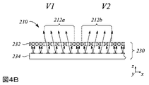
図4Aは、本明細書に記載の原理と一致する実施形態による、一例におけるマルチビューディスプレイ230の一部の斜視図を示す。図4Bは、本明細書に記載の原理と一致する実施形態による、一例における図4Aのマルチビューディスプレイ部分の断面図である。図示のように、マルチビューディスプレイ230は、光バルブ232のアレイとマルチビューバックライト234とを備える。いくつかの実施形態では、マルチビューディスプレイ230、光バルブアレイ、及びマルチビューバックライト234は、それぞれ、上述のマルチビューディスプレイ10、光バルブ30のアレイ、及びマルチビューバックライト40と実質的に同様であってもよい。
FIG. 4A shows a perspective view of a portion of
図4A及び図4Bはまた、限定ではなく例示として、2×2配列のビューブロック212を有するユニットセル210でアライメントパターン200を表示するように構成された光バルブアレイを示す。図示のように、図4A~図4Bのユニットセル210のビューブロック212のそれぞれは、マルチビューディスプレイ230の4つの異なるビューのうちの異なる1つに対応する光を通過させるように構成された光バルブアレイの複数の光バルブ232を含む。特に図4Aは、各ユニットセル210内のアクティブ又は開いた光バルブ232をクロスハッチングで示すとともに、各ユニットセル210内の光を遮断する非アクティブ又は閉じた光バルブをクロスハッチングなしで示している。図4Bは、非アクティブ又は閉じた光バルブ232を「X」で、開いた又はアクティブな光バルブ232を「X」なしで示している。
FIGS. 4A and 4B also illustrate, by way of example and not limitation, a light valve array configured to display
図示のように、ビューブロック212のそれぞれは、アクティブ及び非アクティブにされた光バルブの異なるセットを含み、その異なるセットはマルチビューディスプレイ230の異なるビューに対応する。例えば、ユニットセル210の第1のビューブロック212aは、マルチビューディスプレイ230の第1のビューV1に対応するかその方向における光を通過させるように構成されてもよく、第2のビューブロック212bは、例えば図示のように、マルチビューディスプレイ230の第2のビューV2に対応するかその方向における光を通過させるように構成されてもよい。同様に、他方のビューブロック212は、例えば、第3のビューV3及び第4のビューV4などの他のビューに対応するかその方向における光を通過させるように構成されてもよい。
As shown, each of view blocks 212 includes a different set of activated and deactivated light valves, which correspond to different views of
図4Bはまた、マルチビューバックライト234によって放射された光を、指向性光ビームを表す矢印として示している。指向性光ビームは、例えば、上述のようにマルチビーム要素によって放射されてもよい。図4Bに示すように、第1のビューV1に対応する方向を有する指向性光ビームは、第1のビューブロック212a内のアクティブ又は開いた光バルブ232を通過する。第2のビューV2に対応する方向を有する他の指向性光ビームは、同様に図示されているように、第1のビューブロック212a内の非アクティブ又は閉じた光バルブ232によって遮断される。さらに、図4Bに示すように、第2のビューV2に対応する方向を有する指向性光ビームは、第2のビューブロック212b内のアクティブ又は開いた光バルブ232を通過するが、第1のビューV1に対応する方向を有する他の指向性光ビームは、光バルブアレイの非アクティブ又は閉じた光バルブ232によって遮断される。
FIG. 4B also shows the light emitted by the
再び図2を参照すると、マルチビューバックライトをマルチビューディスプレイの光バルブアレイと位置合わせする方法100は、アライメントパターンを表示するためにマルチビューバックライトを使用して光バルブアレイを照明するステップ120をさらに含む。例えば、マルチビューバックライトは指向性光ビームとして光を放射して例えば図1C及び図4Bに関して上述したように光バルブアレイを照明する(120)。
Referring again to FIG. 2, the
いくつかの実施形態では、光バルブアレイを照明するために使用されるマルチビューバックライトは、図1Cに示す上述のマルチビューディスプレイ10のマルチビューバックライト40と実質的に同様であってもよい。例えば、マルチビューバックライトは、光を導波光として導くように構成された光ガイドと、光ガイドにわたり互いに離隔したマルチビーム要素のアレイとを備えることができる。これらの実施形態によれば、マルチビーム要素アレイの各マルチビーム要素は、例えばマルチビューディスプレイ又はマルチビューディスプレイによって表示されるマルチビュー画像のビュー方向などの、異なるビュー方向に対応する方向を有する複数の指向性光ビームとして、光ガイドから導波光の一部を散乱させるように構成されてもよい。様々な実施形態では、各マルチビーム要素のサイズは、光バルブアレイの光バルブのサイズの1/4~2倍である。さらに、いくつかの実施形態では、マルチビーム要素アレイのマルチビーム要素は、導波光を回折的に散乱させるように構成された回折格子、導波光を反射的に散乱させるように構成されたマイクロ反射要素、及び導波光を屈折的に散乱させるように構成されたマイクロ屈折要素のうちの1つ又は複数を含んでもよい。
In some embodiments, the multi-view backlight used to illuminate the light valve array may be substantially similar to
図2に示すように、マルチビューバックライトをマルチビューディスプレイの光バルブアレイと位置合わせする方法100は、表示されたアライメントパターン内のユニットセルの誤差尺度を最小化するためにマルチビューバックライトと光バルブアレイの相対位置を調整するステップ130をさらに含む。特に、誤差尺度を最小化するために相対位置を調整するステップ130は、光バルブアレイに対してマルチビューバックライトを回転させるステップと、光バルブアレイに対してマルチビューバックライトを並進させるステップとの一方又は両方を含んでもよい。
As shown in FIG. 2, a
いくつかの実施形態では、最小化される誤差尺度は、アライメントパターンの各ユニットセル間の相対輝度差を決定することを含んでもよい。例えば、各ユニットセルの輝度が決定又は測定されてもよい。いくつかの実施形態によれば、相対輝度差はアライメントパターンの各ユニットセルの対応するビューブロック間の輝度差を含んでもよい。別の実施形態では、決定される輝度はユニットセルの全体輝度であってもよく、相対輝度差は、例えば、アライメントパターンの異なるユニットセル間で決定されてもよい。 In some embodiments, the error measure to be minimized may include determining the relative luminance difference between each unit cell of the alignment pattern. For example, the brightness of each unit cell may be determined or measured. According to some embodiments, the relative luminance difference may include the luminance difference between corresponding view blocks of each unit cell of the alignment pattern. In another embodiment, the brightness determined may be the overall brightness of the unit cell, and the relative brightness difference may be determined between unit cells with different alignment patterns, for example.
図5Aは、本明細書に記載の原理と一致する実施形態による、一例における誤差尺度を最小化するためにマルチビューバックライトと光バルブアレイの相対位置を調整するステップ130の前の、照射された光バルブアレイのアライメントパターン200の平面図を示す。図5Bは、本明細書に記載の原理と一致する実施形態による、一例における誤差尺度を最小化するためにマルチビューバックライトと光バルブアレイの相対位置を調整するステップ130後における、図5Aのアライメントパターン200の平面図を示す。図5A~図5Bでは、輝度はアライメントパターン200のユニットセル210のビューブロック212内の影付きで示されており、より濃い影はより高い輝度又はより明るいビューブロック212を表す。図5Aに示すように、アライメントパターン200の異なるユニットセル210は、異なるユニットセル210の様々なビューブロック212において特に、著しく異なる輝度を有する。しかしながら、誤差尺度を最小化するためにマルチビューバックライトと光バルブアレイの相対位置を調整するステップ130の後、異なるユニットセル210は、図5Bに示すように非常に類似した輝度を有する。したがって、相対輝度差によって表される誤差尺度は、調整するステップ130後、図5Bに示すように最小化されている。
FIG. 5A shows illuminated light beams before
いくつかの実施形態では、誤差尺度を最小化するために相対位置を調整するステップ130は、ユニットセルの目標位置に対する、表示されたアライメントパターン内のユニットセル輝度重心の位置ずれを最小化するステップを含む。すなわち、アライメントパターンの各ユニットセルのユニットセル輝度の重心は、光学的に測定されてもよく、又は他の方法で決定されてもよい。次いで、アライメントパターンの様々なユニットセルのユニットセル輝度重心の位置は、個々のユニットセルのそれぞれについて、最小化すべき誤差尺度として目標位置と比較してもよい。すなわち、ユニットセル輝度重心の位置ずれを誤差尺度として採用してもよい。いくつかの実施形態では、ユニットセル輝度重心の位置ずれは、表示されたアライメントパターン内の個々のユニットセル輝度重心の観察位置と個々のユニットセルの対応する目標位置との間の平方差の和を最小化することを含む。
In some embodiments, adjusting the
図6は、本明細書に記載の原理と一致する実施形態による、一例におけるユニットセル輝度重心214の図式表示を示す。特に図6は、図5A~図5Bに示すアライメントパターン200及びユニットセル210などの、光バルブアレイにわたって分布したアライメントパターン内の対応する複数のユニットセルについて測定又は決定されたユニットセル輝度の複数の重心214を示す。図6に示すユニットセル輝度重心214は、例えば、誤差尺度を最小化するために相対位置を調整するステップ130中に決定されていてもよい。ユニットセルの目標位置216も、ユニットセル目標位置のそれぞれに対して、例として「丸で囲んだx」で示されている。目標位置216に対する様々なユニットセル輝度重心214の位置ずれは、マルチビューバックライトと光バルブアレイの相対位置を調整するステップ130中に最小化して誤差尺度を最小化してもよい。
FIG. 6 shows a graphical representation of the unit
本明細書に記載の原理の他の実施形態によれば、マルチビューディスプレイバックライト位置合わせシステムが提供される。図7は、本明細書に記載の原理と一致する実施形態による、一例におけるマルチビューディスプレイバックライト位置合わせシステム300のブロック図を示す。様々な実施形態によれば、マルチビューディスプレイバックライト位置合わせシステム300を使用して、マルチビューディスプレイの製造を容易にすることができる。例えば、位置合わせする方法は、マルチビューディスプレイが例えば図1Cで例示されたマルチビューディスプレイ10と実質的に同様である場合に、マルチビューディスプレイの光バルブのアレイ及びマルチビューバックライトの位置合わせを容易にしてもよい。
According to another embodiment of the principles described herein, a multi-view display backlight alignment system is provided. FIG. 7 shows a block diagram of an example multi-view display backlight alignment system 300, according to an embodiment consistent with principles described herein. According to various embodiments, multi-view display backlight alignment system 300 can be used to facilitate manufacturing of multi-view displays. For example, the alignment method can align an array of light valves and a multi-view backlight of a multi-view display when the multi-view display is substantially similar to the
様々な実施形態によれば、図7に示すマルチビューディスプレイバックライト位置合わせシステム300は、光バルブ312のアレイを有するマルチビューディスプレイ310と、マルチビューバックライト314とを備える。光バルブアレイは、マルチビューバックライト314によって照射されると、複数のユニットセルを含む表示されたアライメントパターンを供給するように構成される。例えば、アレイの光バルブ312は、表示されたアライメントパターンを供給するためにディスプレイドライバ(図示せず)によって駆動されてもよい。さらに、様々な実施形態によれば、複数のユニットセルのユニットセルは互いに離隔しており、各ユニットセルは、マルチビューディスプレイ310の異なるビュー、又は等価的にマルチビューディスプレイ310によって表示されるマルチビュー画像に対応する異なるビュー方向を有する複数のビューブロックを含む。さらに、複数のビューブロックのビューブロックは、異なるビューの配置に対応するユニットセル内の配置を有する。いくつかの実施形態では、アライメントパターン及び複数のユニットセルは、上述したように、マルチビューバックライトをマルチビューディスプレイの光バルブアレイと位置合わせする方法100で説明されかつ採用されるアライメントパターン200及びユニットセル210と実質的に同様であってもよい。
According to various embodiments, the multi-view display backlight alignment system 300 shown in FIG. 7 comprises a
いくつかの実施形態では、光バルブ312のアレイは、上述の光バルブアレイと実質的に同様であってもよい。例えば、光バルブ312のアレイは、液晶光バルブ、電気泳動光バルブ、及びエレクトロウェッティングに基づく光バルブのうちの1つ又は複数を備えてもよい。
In some embodiments, the array of
いくつかの実施形態では、マルチビューバックライト314は、マルチビューバックライトをマルチビューディスプレイの光バルブアレイと位置合わせする上述の方法100に関して上述したマルチビューバックライトと実質的に同様であってもよい。例えば、マルチビューバックライト314は、光ガイドと、光ガイドにわたって互いに離隔したマルチビーム要素のアレイとを備えてもよい。光ガイドは、光ガイドの長さに沿って導波光として光を導くように構成されてもよい。さらに、様々な実施形態によれば、マルチビーム要素アレイの各マルチビーム要素は、マルチビューディスプレイ310のビューの異なるビュー方向に対応する方向を有する指向性光ビーム(複数の指向性光ビームなど)として、光ガイドから導波光の一部を散乱させるように構成されてもよい。さらに、いくつかの実施形態では、各マルチビーム要素のサイズは、光バルブアレイの光バルブのサイズの1/4~2倍である。
In some embodiments,
図7に示すように、マルチビューディスプレイバックライト位置合わせシステム300は、位置決めステージ320をさらに備える。位置決めステージ320は、光バルブ312のアレイとマルチビューバックライト314との相対位置を調整するように構成される。位置決めステージ320は、例えば、光バルブアレイ及びマルチビューバックライト314の一方又は両方を物理的に移動させて相対位置を調整してもよい。さらに、位置決めステージ320によって提供される調整は、表示されたアライメントパターン内のユニットセルの誤差尺度を最小化するように構成される。様々な実施形態によれば、光バルブアレイとマルチビューバックライト314との間の相対位置の調整を提供する実質的に任意の位置決めステージを、位置決めステージ320として採用してもよい。例えば、位置決めステージ320は、x軸及びy軸の一方又は両方において運動を提供するマイクロメータステージを備えてもよい。別の例では、位置決めステージ320は、x軸及びy軸における動きの一方又は両方の代わりに、又はそれに加えて、光バルブアレイとマルチビューバックライト314の相対回転を提供してもよい。いくつかの実施形態では、位置決めステージ320は、マルチビューバックライト314と光バルブアレイの相対回転及び相対並進の一方又は両方を提供するように構成されたモータ駆動ステージを備えてもよい。
As shown in FIG. 7, multi-view display backlight alignment system 300 further comprises
いくつかの実施形態(図7には図示せず)では、マルチビューディスプレイバックライト位置合わせシステム300は、カメラをさらに備えてもよい。カメラは、マルチビューディスプレイ310に設けられた表示されたアライメントパターンを撮像するように構成される。様々な実施形態によれば、表示されたアライメントパターンの撮像画像から誤差尺度を決定することができる。例えば、撮像された画像は、上述したように輝度を測定するか輝度重心を決定するためにグラフィックス処理ユニット(GPU)を使用して分析されてもよい。次いで、誤差尺度は、例えば輝度測定値からGPU又は別のプロセッサによって生成されてもよい。
In some embodiments (not shown in FIG. 7), multi-view display backlight alignment system 300 may further comprise a camera. The cameras are configured to image the displayed alignment pattern provided on the
本明細書に記載の原理の他の実施形態によれば、自動化マルチビューディスプレイバックライト位置合わせシステムが提供される。図8は、本明細書に記載の原理と一致する実施形態による、一例における自動化マルチビューディスプレイバックライト位置合わせシステム400のブロック図を示す。図8に示すように、自動化マルチビューディスプレイバックライト位置合わせシステム400は、マルチビューディスプレイ410のマルチビューバックライト414によって照明されたときに表示されたアライメントパターンを供給するように構成された光バルブ412のアレイを有するマルチビューディスプレイ410を備える。様々な実施形態によれば、アライメントパターンは、複数の離隔したユニットセルを含む。さらに、離隔したユニットセルのそれぞれは、マルチビューディスプレイの異なるビューに対応する異なるビュー方向を有する複数のビューブロックを備える。また、様々な実施形態によれば、離隔したユニットセルのビューブロックは、異なるビューの配置に対応する配置を有する。
According to another embodiment of the principles described herein, an automated multi-view display backlight alignment system is provided. FIG. 8 shows a block diagram of an example automated multi-view display
いくつかの実施形態では、マルチビューディスプレイ410は、上述のマルチビューディスプレイ310と実質的に同様である。同様に、ビューブロック及びユニットセルを含むアライメントパターンは、同様に上述したアライメントパターン200、ビューブロック212、ユニットセル210と実質的に同様であってもよい。
In some embodiments,
図8に示す自動化マルチビューディスプレイバックライト位置合わせシステム400は、モータ駆動位置決めステージ420と、フィードバックコントローラ430とをさらに備える。モータ駆動位置決めステージ420は、マルチビューディスプレイ410の光バルブアレイとマルチビューバックライトとの相対位置を調整するように構成される。フィードバックコントローラ430は、モータ駆動位置決めステージ420を駆動して、表示されたアライメントパターン内の離隔したユニットセルの誤差尺度を最小にするように構成される。フィードバックコントローラ430は、例えば、プロセッサ及びモータコントローラを備えてもよい。
Automated multi-view display
いくつかの実施形態によれば、自動化マルチビューディスプレイバックライト位置合わせシステム400は、図8に示すように、マルチビューディスプレイ410上に設けられ、表示されたアライメントパターンの画像を撮像するように構成されたカメラ440をさらに備えてもよい。これらの実施形態では、フィードバックコントローラ430は、カメラ440によって供給される表示されたアライメントパターン画像の撮像画像の誤差尺度を決定するように構成されてもよい。いくつかの実施形態では、誤差尺度は、アライメントパターンの各ユニットセル間の相対輝度差、及びユニットセルの目標位置に対する表示されたアライメントパターン内のユニットセル輝度重心の位置ずれの一方又は両方を含んでもよい。
According to some embodiments, an automated multi-view display
さらに、フィードバックコントローラ430は、相対輝度差又はユニットセル輝度重心を決定し、次いで、多数の異なる分析技術のいずれかを実施して誤差尺度を決定し最小化してもよい。以下は、様々な実施形態による、誤差最小化をもたらすためにフィードバックコントローラ430のプロセッサによって実施され得る、これらの技術のいくつかのより詳細な説明である。
Additionally,
マルチビューアライメントパターンを使用した位置合わせの定量化
様々な実施形態によれば、マルチビューアライメント輝度パターンは、マルチビューディスプレイの複数のスーパーピクセルに対応し得る複数のユニットセルを指定していてもよい。例えば、各ユニットセルは、中心座標(xi,yi)∀i≦Nを有してもよい。誤差尺度を決定し最小化するための例示的なプロセスに関して、撮像装置又はカメラは、1つ又は複数の設計されたビュー位置で照明されたバックライト及び光バルブアレイアセンブリの画像を撮像するように構成されてもよい。さらに、そのような撮像装置又はカメラは、バックライト及び光バルブアレイアセンブリの視野(FOV)の中心に構成されてもよい。表示された輝度パターンの撮像画像から、カメラキャリブレーションを用いて、照明された中心座標L(x,y)を算出してもよい。例えば、N個のユニットセルのそれぞれ内のピクセル重心
![]()

![]()
様々な実施形態によれば、位置合わせの誤差尺度は様々な適切な技術を用いて計算してもよい。一実施形態では、残差平方和(SSR)値を計算して、例えば式(3)によって、各重心とユニットセルの各中心との間の距離R、又はカメラの視線位置に対して予想される他の何らかの座標(xi,yi)を評価してもよい。
![]()
![]()
![]()
![]()
![]()
![]()
別の実施形態では、重心座標
![]()
![]()
いくつかの実施形態によれば、分解の代わりに、回転、並進及び伸長変換を直接計算してもよい。一例では、並進、回転、及び拡大縮小(又は伸長)を表す透視変換であるホモグラフィを用いてもよい。数学的には、ホモグラフィ行列Hpは、以下のように、拡大縮小を表すKp行列、回転を表すRp行列、及び並進を表すTp行列に分解することができる。
Hp=Kp[Rp|Tp](4)


H p =K p [R p |T p ] (4)
さらに、各行列要素について、合否閾値を、バックライトと光バルブアレイとの間の位置合わせ度に関する品質管理度を微調整するように構成してもよい。ここでは、例えば、マルチビューディスプレイの外観への影響に基づいて合否閾値を定義してもよい。このようにして、当該手法は、品質管理に関する様々な対応粒度やカスタム粒度についてSSR技術を用いる方法よりも細かくする。また、ピクセル単位で計測されたこれらのパラメータを物理単位に変換してもよい。変換された物理単位の測定値に基づいて、要求事項を品質管理仕様書に定義してもよい。 Additionally, for each matrix element, pass/fail thresholds may be configured to fine-tune the degree of quality control with respect to the degree of alignment between the backlight and the light valve array. Here, for example, a pass/fail threshold may be defined based on the effect on the appearance of the multi-view display. In this way, the approach is more granular than methods using SSR technology for various supported and custom granularities of quality control. Also, these parameters measured in pixels may be converted to physical units. Based on the converted physical unit measurements, requirements may be defined in the quality control specification.
マルチビューアライメントパターンを使用したアクティブな位置合わせ
様々な実施形態によれば、ディスプレイとバックライトの位置合わせは、上述のように測定された位置ずれパラメータに基づいて調整されてもよい。例えば、これらのコンポーネントの位置合わせを調整するステップは、マルチビューディスプレイ製造業者の内部プロセスとして実行されてもよい。別の例では、バックライトと光バルブアレイとの間の位置合わせが変わっていないことを確実にするために、外部のマルチビューディスプレイ製造業者による製品組立て現場で調整プロセスが実行されてもよい。
Active Alignment Using Multi-View Alignment Patterns According to various embodiments, the alignment of the display and backlight may be adjusted based on the misalignment parameters measured as described above. For example, adjusting the alignment of these components may be performed as an internal process of the multi-view display manufacturer. In another example, an alignment process may be performed at the product assembly site by an external multi-view display manufacturer to ensure that the alignment between the backlight and the light valve array has not changed.
いくつかの実施形態では、バックライトと光バルブアレイとの間の検出された位置ずれを改善するために、数値最適化を利用してもよい。さらに、当該最適化は、バックライトと光バルブアレイとの間の位置合わせを改善するために反復的に実行されてもよい。1つの例示的な反復では、マルチビューディスプレイの画像は、カメラ又は光センサを使用して撮像される。次に、SSR値及び/又は計算されたSSR値を最小化する1つ若しくは複数の変換が計算され、メリット関数が生成される。メリット関数が与えられると、メリット関数によって計算された結果を最小化するように様々なマルチビューバックライト位置合わせパラメータを修正、操作、又はその他の方法で更新することができる。例えば、回転、並進、及び光バルブアレイまでの距離などの位置合わせパラメータの1つ又は複数の調整を実行して、メリット関数の結果を最小化してもよい。 In some embodiments, numerical optimization may be used to improve the detected misalignment between the backlight and the light valve array. Additionally, the optimization may be performed iteratively to improve alignment between the backlight and the light valve array. In one exemplary iteration, images of the multi-view display are captured using cameras or optical sensors. The SSR value and/or one or more transformations that minimize the calculated SSR value are then calculated to generate a merit function. Given a merit function, various multi-view backlight alignment parameters can be modified, manipulated, or otherwise updated to minimize the result computed by the merit function. For example, one or more adjustments of alignment parameters such as rotation, translation, and distance to the light valve array may be performed to minimize the result of the merit function.
他の実施形態では、SSRを最小化する1つ又は複数の幾何学的変換又は透視変換が計算される。次に、変換は、1つ又は複数の位置合わせパラメータのセットに分解することができる。例えば、そのような変換は、並進値(画像ピクセルにおけるtx,ty)、回転値(光軸を中心とした、平面内の度であるθ)、及び伸長値(無次元単位のsx,sy)のうちの1つ又は複数に分解することができる。 In other embodiments, one or more geometric or perspective transforms that minimize SSR are computed. The transform can then be decomposed into a set of one or more alignment parameters. For example, such transformations include translation values (t x , t y in image pixels), rotation values (θ, in degrees in the plane about the optical axis), and elongation values (s x , s y ).
ピクセル計算の物理単位計算への変換
上述したように、照明されたアライメントパターンの画像分析を用いて位置合わせパラメータを計算してもよい。画像ピクセルで計算されたこれらのパラメータは、バックライト及び光バルブアレイを位置合わせするための物理的調整を実行できるように、物理単位に変換されてもよい。例えば、物理的なバックライト位置合わせを調整して並進ずれを補正するために、画像ピクセル単位の並進パラメータ値を物理単位の値に変換する必要がある。
Conversion of Pixel Calculations to Physical Unit Calculations As described above, image analysis of the illuminated alignment pattern may be used to calculate registration parameters. These parameters calculated in image pixels may be converted to physical units so that physical adjustments can be made to align the backlight and light valve array. For example, translational parameter values in image pixel units need to be converted to values in physical units in order to adjust the physical backlight alignment to compensate for translational misalignment.
様々な実施形態によれば、並進値は様々な技術を用いて物理単位の値に変換してもよい。例えば、マルチビューディスプレイのサイズは一般的に知られている。ディスプレイのサイズが与えられ、画像ピクセルの単位をディスプレイピクセルの単位に変換してもよい。次に、ユニットセル内の各「単一のビュー領域」又はビューブロックのサイズ(ピクセル単位のdx,dy)が与えられ、ディスプレイピクセルの単位をビューの単位に変換してもよい。一例では、当該変換は、以下のように重心からユニットセル中心を減算することによって計算してもよい。

![]()
![]()
さらに、いくつかの実施形態では、異なるパターン設計に応じて異なる変換を計算してもよい。重心がビューで表されると、これらの座標値をマルチビューディスプレイのサイズ及びジオメトリに基づいて物理的な長さの単位に変換することができる。全てのマルチビューディスプレイについて、アライメントパターン画像内の1つのビューの並進は、長さ(ミクロン単位のΔx,y)の並進と等価である。したがって、ディスプレイのミクロン単位のグローバル変換は、以下のように計算してもよい。

同様に、回転を物理単位に変換してもよい。ディスプレイをまたぐ回転によって引き起こされる垂直ビュー転換は、以下のように計算される。

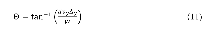
伸長(sx,sy)は以下のように物理量に変換してもよい。


以上のように、マルチビューバックライトとマルチビューディスプレイの光バルブアレイとの位置合わせを提供する様々なマルチビューディスプレイバックライト位置合わせシステムと共に、マルチビューバックライトを光バルブアレイと位置合わせする方法の例及び実施形態を説明した。上述の例は、本明細書に記載の原理を表す多くの具体例のうちのいくつかの単なる例示であることを理解されたい。明らかに、当業者は、以下の特許請求の範囲によって規定される範囲から逸脱することなく、多数の他の構成を容易に考案することができる。 Thus, various multi-view display backlight alignment systems that provide alignment between the multi-view backlight and the light valve array of the multi-view display, as well as methods of aligning the multi-view backlight with the light valve array. Examples and embodiments have been described. It should be understood that the above-described examples are merely illustrative of some of the many implementations that illustrate the principles described herein. Clearly, those skilled in the art can readily devise numerous other arrangements without departing from the scope defined by the following claims.
Claims (20)
互いに離隔したユニットセルを有するアライメントパターンを前記光バルブアレイ上に確立するステップであって、前記アライメントパターンの各ユニットセルが前記マルチビューディスプレイの異なるビューに対応する異なるビュー方向を有する複数のビューブロックを備えるステップと、
前記アライメントパターンを表示するために前記マルチビューバックライトを使用して前記光バルブアレイを照明するステップと、
前記表示されたアライメントパターン内の前記ユニットセルの誤差尺度を最小化するために、前記マルチビューバックライトと前記光バルブアレイの相対位置を調整するステップとを含み、前記誤差尺度が、前記表示されたアライメントパターンの前記ユニットセルのそれぞれの間の相対輝度差を含む、ステップと、
各ユニットセル内のビューブロックの配置が前記マルチビューディスプレイのビューの配置に対応し、
前記マルチビューバックライトが、マルチビーム要素のアレイを備え、前記マルチビーム要素のアレイの各マルチビーム要素が、前記異なるビュー方向に対応する方向を有する複数の指向性光ビームを提供して、前記光バルブアレイを照明するように構成されている、マルチビューバックライトを位置合わせする方法。 A method of aligning a light valve array and a multi-view backlight in a multi-view display, the method comprising:
establishing an alignment pattern on the light valve array having unit cells spaced apart from each other, wherein each unit cell of the alignment pattern has a plurality of view blocks with different view directions corresponding to different views of the multi-view display. a step comprising
illuminating the light valve array using the multi-view backlight to display the alignment pattern;
adjusting the relative positions of the multi-view backlight and the light valve array to minimize an error measure of the unit cells in the displayed alignment pattern, wherein the error measure is the displayed alignment pattern. relative luminance difference between each of the unit cells of the aligned pattern;
the arrangement of view blocks in each unit cell corresponds to the arrangement of views of the multi-view display;
wherein the multi-view backlight comprises an array of multi-beam elements, each multi-beam element of the array of multi-beam elements providing a plurality of directional light beams having directions corresponding to the different viewing directions; A method of aligning a multi-view backlight configured to illuminate an array of light valves .
2. The aligning multi-view backlight of claim 1, wherein the arrangement of views of the multi-view display comprises a two-dimensional array of views, each unit cell of the alignment pattern having a corresponding two-dimensional array of view blocks. Method.
導波光として光を導くように構成された光ガイドと、
前記光ガイドにわたり互いに離隔した前記マルチビーム要素のアレイであって、前記マルチビーム要素アレイの各マルチビーム要素が、前記複数の指向性光ビームとして前記光ガイドからの前記導波光の一部を散乱させるように構成されたマルチビーム要素のアレイとを備え、
各マルチビーム要素のサイズが、前記光バルブアレイの光バルブのサイズの1/4~2倍である、請求項1に記載のマルチビューバックライトを位置合わせする方法。 The multi-view backlight is
a light guide configured to guide light as guided light;
an array of said multibeam elements spaced apart across said light guide, wherein each multibeam element of said multibeam element array scatters a portion of said guided light from said light guide as said plurality of directional light beams. an array of multibeam elements configured to cause
2. A method of aligning a multi-view backlight according to claim 1, wherein the size of each multi-beam element is 1/4 to 2 times the size of a light valve in said light valve array.
光バルブのアレイとマルチビューバックライトとを有するマルチビューディスプレイであって、前記光バルブアレイが、前記マルチビューバックライトによって照射されたときに複数のユニットセルを含む表示されたアライメントパターンを生成するように構成されているマルチビューディスプレイと、
前記光バルブアレイと前記マルチビューバックライトの相対位置を調整して、前記表示されたアライメントパターン内の前記ユニットセルの誤差尺度を最小化するように構成された位置決めステージであって、前記誤差尺度が、前記表示されたアライメントパターンの前記ユニットセルのそれぞれの間の相対輝度差を含む、位置決めステージとを備え、
前記複数のユニットセルのユニットセルが互いに離隔しており、各ユニットセルが、前記マルチビューディスプレイの異なるビューに対応する異なるビュー方向を有し、かつ前記異なるビューの配置に対応する配置を有する複数のビューブロックを備え、
前記マルチビューバックライトが、マルチビーム要素のアレイを備え、前記マルチビーム要素のアレイの各マルチビーム要素が、前記異なるビュー方向に対応する方向を有する複数の指向性光ビームを提供して、前記光バルブアレイを照明するように構成されている、マルチビューディスプレイバックライト位置合わせシステム。 A multi-view display backlight alignment system comprising:
A multi-view display having an array of light valves and a multi-view backlight, wherein the light valve array produces a displayed alignment pattern comprising a plurality of unit cells when illuminated by the multi-view backlight. a multi-view display configured as
a positioning stage configured to adjust the relative positions of the light valve array and the multi-view backlight to minimize an error measure of the unit cells within the displayed alignment pattern , wherein the error measure is includes relative luminance differences between each of the unit cells of the displayed alignment pattern ;
unit cells of the plurality of unit cells are separated from each other, each unit cell having a different view direction corresponding to a different view of the multi-view display, and having an arrangement corresponding to the arrangement of the different views; with a view block of
wherein the multi-view backlight comprises an array of multi-beam elements, each multi-beam element of the array of multi-beam elements providing a plurality of directional light beams having directions corresponding to the different viewing directions; A multi-view display backlight alignment system configured to illuminate an array of light valves .
導波光として光を導くように構成された光ガイドと、
前記光ガイドにわたり互いに離隔した前記マルチビーム要素のアレイであって、前記マルチビーム要素アレイの各マルチビーム要素が、前記指向性光ビームとして前記光ガイドからの前記導波光の一部を散乱させるように構成されたマルチビーム要素のアレイとを備え、
各マルチビーム要素のサイズが、前記光バルブアレイの光バルブのサイズの1/4~2倍である、請求項11に記載のマルチビューディスプレイバックライト位置合わせシステム。 The multi-view backlight is
a light guide configured to guide light as guided light;
an array of said multibeam elements spaced apart across said light guide, such that each multibeam element of said multibeam element array scatters a portion of said guided light from said light guide as said directional light beam. an array of multibeam elements configured in
12. The multi-view display backlight alignment system of claim 11 , wherein the size of each multi-beam element is 1/4 to 2 times the size of a light valve in said light valve array.
マルチビューディスプレイであって、前記マルチビューディスプレイのマルチビューバックライトによって照明されると、表示されたアライメントパターンを生成するように構成された光バルブのアレイを有するマルチビューディスプレイと、
前記光バルブアレイと前記マルチビューバックライトの相対位置を調整するように構成されたモータ駆動位置決めステージと、
前記モータ駆動位置決めステージを駆動して、前記表示されたアライメントパターン内の離隔したユニットセルの誤差尺度を最小化するように構成されたフィードバックコントローラであって、前記誤差尺度が、前記表示されたアライメントパターンの前記ユニットセルのそれぞれの間の相対輝度差を含むフィードバックコントローラとを備え、
前記アライメントパターンが複数の前記離隔したユニットセルを備え、前記離隔したユニットセルのそれぞれが、前記マルチビューディスプレイの異なるビューに対応する異なるビュー方向を有し、かつ前記異なるビューの配置に対応する配置を有する複数のビューブロックを備え、
前記マルチビューバックライトが、マルチビーム要素のアレイを備え、前記マルチビーム要素のアレイの各マルチビーム要素が、前記異なるビュー方向に対応する方向を有する複数の指向性光ビームを提供して、前記光バルブアレイを照明するように構成されている、自動化マルチビューディスプレイバックライト位置合わせシステム。 An automated multi-view display backlight alignment system comprising:
a multi-view display having an array of light valves configured to produce a displayed alignment pattern when illuminated by a multi-view backlight of the multi-view display;
a motorized positioning stage configured to adjust the relative positions of the light valve array and the multi-view backlight;
A feedback controller configured to drive the motorized positioning stage to minimize an error measure for spaced unit cells in the displayed alignment pattern , wherein the error measure is a feedback controller containing relative luminance differences between each of said unit cells of a pattern ;
The alignment pattern comprises a plurality of the spaced unit cells, each spaced unit cell having a different view direction corresponding to a different view of the multi-view display, and an arrangement corresponding to the arrangement of the different views. comprising a plurality of view blocks with
wherein the multi-view backlight comprises an array of multi-beam elements, each multi-beam element of the array of multi-beam elements providing a plurality of directional light beams having directions corresponding to the different viewing directions; An automated multi-view display backlight alignment system configured to illuminate a light valve array .
導波光として光を導くように構成された光ガイドと、
前記光ガイドにわたり互いに離隔した前記マルチビーム要素のアレイであって、前記マルチビーム要素アレイの各マルチビーム要素が、前記複数の指向性光ビームとして前記光ガイドからの前記導波光の一部を散乱させるように構成されたマルチビーム要素のアレイとを含み、
各マルチビーム要素のサイズが、前記光バルブアレイの光バルブのサイズの1/4~2倍であり、
前記マルチビーム要素アレイのマルチビーム要素が、前記導波光を回折的に散乱させるように構成された回折格子、前記導波光を反射的に散乱させるように構成されたマイクロ反射要素、及び前記導波光を屈折的に散乱させるように構成されたマイクロ屈折要素のうちの1つ又は複数を備える、請求項17に記載の自動化マルチビューディスプレイバックライト位置合わせシステム。
The multi-view backlight is
a light guide configured to guide light as guided light;
an array of said multibeam elements spaced apart across said light guide, wherein each multibeam element of said multibeam element array scatters a portion of said guided light from said light guide as said plurality of directional light beams. an array of multibeam elements configured to cause
the size of each multibeam element is 1/4 to 2 times the size of the light valves of the light valve array;
A diffraction grating, wherein the multibeam elements of the multibeam element array are configured to diffractively scatter the guided light, micro reflective elements configured to reflectively scatter the guided light, and the guided light. 18. The automated multi-view display backlight alignment system of claim 17 , comprising one or more of the micro-refractive elements configured to refractively scatter .
Applications Claiming Priority (3)
| Application Number | Priority Date | Filing Date | Title |
|---|---|---|---|
| US201962828398P | 2019-04-02 | 2019-04-02 | |
| US62/828,398 | 2019-04-02 | ||
| PCT/US2020/026430 WO2020206151A1 (en) | 2019-04-02 | 2020-04-02 | Multiview display alignment method and system |
Publications (2)
| Publication Number | Publication Date |
|---|---|
| JP2022523875A JP2022523875A (en) | 2022-04-26 |
| JP7213370B2 true JP7213370B2 (en) | 2023-01-26 |
Family
ID=72666395
Family Applications (1)
| Application Number | Title | Priority Date | Filing Date |
|---|---|---|---|
| JP2021559072A Active JP7213370B2 (en) | 2019-04-02 | 2020-04-02 | Multi-view display alignment method and system |
Country Status (8)
| Country | Link |
|---|---|
| US (1) | US11442221B2 (en) |
| EP (1) | EP3948411A4 (en) |
| JP (1) | JP7213370B2 (en) |
| KR (1) | KR102586392B1 (en) |
| CN (1) | CN113728269B (en) |
| CA (1) | CA3133396C (en) |
| TW (1) | TWI738283B (en) |
| WO (1) | WO2020206151A1 (en) |
Families Citing this family (2)
| Publication number | Priority date | Publication date | Assignee | Title |
|---|---|---|---|---|
| WO2020223134A1 (en) | 2019-04-28 | 2020-11-05 | Leia Inc. | Method of fabricating diffractive backlight |
| US20230351602A1 (en) * | 2020-08-17 | 2023-11-02 | Thrive Bioscience, Inc. | Cell segmentation image processing methods |
Citations (2)
| Publication number | Priority date | Publication date | Assignee | Title |
|---|---|---|---|---|
| JP2009223194A (en) | 2008-03-18 | 2009-10-01 | Toshiba Corp | Apparatus and method for manufacturing three-dimensional image display |
| JP2018533262A (en) | 2015-09-05 | 2018-11-08 | レイア、インコーポレイテッドLeia Inc. | Multi-view display with head tracking |
Family Cites Families (48)
| Publication number | Priority date | Publication date | Assignee | Title |
|---|---|---|---|---|
| JPH10333536A (en) * | 1997-06-04 | 1998-12-18 | Sharp Corp | Diffracted light generator and panel positioning method |
| GB0322681D0 (en) * | 2003-09-27 | 2003-10-29 | Koninkl Philips Electronics Nv | Multi-view display |
| US8493422B2 (en) * | 2008-04-24 | 2013-07-23 | Kodak Graphic Communications Canada Company | Color filter layer alignment |
| JP2009300816A (en) * | 2008-06-16 | 2009-12-24 | Seiko Epson Corp | Method and device for manufacturing display device |
| TWI428645B (en) | 2008-06-30 | 2014-03-01 | Cpt Technology Group Co Ltd | Color light guide panel and liquid crystal display device |
| CN102906627B (en) * | 2010-05-21 | 2015-08-19 | 皇家飞利浦电子股份有限公司 | Multi-view display device |
| WO2012038856A1 (en) | 2010-09-21 | 2012-03-29 | Koninklijke Philips Electronics N.V. | Multi-view display device |
| JP2012237961A (en) * | 2011-04-28 | 2012-12-06 | Sony Corp | Display device and electronic apparatus |
| TW201326972A (en) | 2011-12-30 | 2013-07-01 | Ind Tech Res Inst | Display apparatus |
| US9389415B2 (en) | 2012-04-27 | 2016-07-12 | Leia Inc. | Directional pixel for use in a display screen |
| US9459461B2 (en) | 2012-05-31 | 2016-10-04 | Leia Inc. | Directional backlight |
| US9201270B2 (en) | 2012-06-01 | 2015-12-01 | Leia Inc. | Directional backlight with a modulation layer |
| KR101977251B1 (en) * | 2012-12-18 | 2019-08-28 | 엘지디스플레이 주식회사 | Multi-view autostereoscopic image display and method of controlling optimal viewing distance |
| US9298168B2 (en) | 2013-01-31 | 2016-03-29 | Leia Inc. | Multiview 3D wrist watch |
| EP2938919B1 (en) | 2013-07-30 | 2018-10-24 | LEIA Inc. | Multibeam diffraction grating-based backlighting |
| KR101856568B1 (en) * | 2013-09-16 | 2018-06-19 | 삼성전자주식회사 | Multi view image display apparatus and controlling method thereof |
| US9519152B2 (en) * | 2013-12-06 | 2016-12-13 | Asm Technology Singapore Pte Ltd | 3D display alignment method |
| US9557466B2 (en) | 2014-07-30 | 2017-01-31 | Leia, Inc | Multibeam diffraction grating-based color backlighting |
| US20160091786A1 (en) * | 2014-09-30 | 2016-03-31 | Google Inc. | Screen configuration for display system |
| JP5861797B1 (en) | 2014-10-06 | 2016-02-16 | オムロン株式会社 | Optical device |
| KR102370062B1 (en) * | 2014-11-24 | 2022-03-04 | 삼성전자주식회사 | Method of determining calibration parameter for 3d display device and 3d display device thereof |
| CN104460115B (en) | 2014-12-31 | 2017-09-01 | 苏州大学 | A multi-view pixel pointing type backlight module and naked-eye 3D display device |
| CA2990591C (en) | 2015-03-30 | 2021-12-21 | Leia Inc. | 2d/3d mode-switchable electronic display with dual layer backlight |
| US10798371B2 (en) | 2015-09-05 | 2020-10-06 | Leia Inc. | Multiview display with head tracking |
| WO2017131816A1 (en) | 2016-01-30 | 2017-08-03 | Leia Inc. | Privacy display and dual-mode privacy display system |
| US10802212B2 (en) | 2015-09-05 | 2020-10-13 | Leia Inc. | Angular subpixel rendering multiview display using shifted multibeam elements |
| WO2017131807A1 (en) | 2016-01-30 | 2017-08-03 | Leia Inc. | Multibeam element-based backlight and display using same |
| ES2905638T3 (en) * | 2015-09-05 | 2022-04-11 | Leia Inc | Dual surface collimator and 3D electronic display employing network-based backlight using this collimator |
| CA2993850C (en) | 2015-09-05 | 2021-11-09 | Leia Inc. | Angular subpixel rendering multiview display using shifted multibeam diffraction gratings |
| EP3408699B1 (en) | 2016-01-30 | 2023-10-11 | LEIA Inc. | Multibeam element-based backlighting having converging views |
| EP3464994B1 (en) | 2016-05-23 | 2023-06-07 | LEIA Inc. | Diffractive multibeam element-based backlighting |
| US10705281B2 (en) | 2016-10-05 | 2020-07-07 | Leia Inc. | Mode-selectable backlight, method, and display employing directional scattering features |
| CN110168280A (en) | 2016-12-28 | 2019-08-23 | 镭亚股份有限公司 | Multi-view display with reflective support structure |
| WO2018125103A1 (en) | 2016-12-28 | 2018-07-05 | Leia Inc. | Multiview backlighting employing fluorescent multibeam elements |
| WO2018140063A1 (en) | 2017-01-30 | 2018-08-02 | Leia Inc. | Multiview backlighting employing plasmonic multibeam elements |
| WO2018160173A1 (en) | 2017-02-28 | 2018-09-07 | Leia Inc. | Multiview backlighting having a color-tailored emission pattern |
| JP7046972B2 (en) | 2017-03-25 | 2022-04-04 | レイア、インコーポレイテッド | Directional backlight, backlit display and method |
| KR102353701B1 (en) | 2017-04-02 | 2022-01-20 | 레이아 인코포레이티드 | Dual View Zone Backlight, Dual-Mode Display, and Method |
| CN110462287B (en) * | 2017-04-04 | 2022-07-08 | 镭亚股份有限公司 | Single sided backlight, multiview display and method employing tilted diffraction grating |
| KR102303654B1 (en) | 2017-04-08 | 2021-09-17 | 레이아 인코포레이티드 | Multi-view backlight, mode-switchable multi-view backlight, and 2D/3D mode-switchable display |
| WO2018213101A1 (en) | 2017-05-14 | 2018-11-22 | Leia Inc. | Multiview backlight, display, and method employing active emitters |
| KR102337899B1 (en) * | 2017-09-01 | 2021-12-09 | 주식회사 엘지화학 | A Drilling Apparatus for Removing Pluggings in a Drain Line |
| WO2019125394A1 (en) | 2017-12-18 | 2019-06-27 | Leia Inc. | Multibeam element-based near-eye display, system, and method |
| KR102422979B1 (en) | 2017-12-18 | 2022-07-21 | 레이아 인코포레이티드 | Mode-Switchable Backlight, Display and Method |
| JP7011066B2 (en) | 2017-12-21 | 2022-02-10 | レイア、インコーポレイテッド | Mode selectable backlight, privacy display, and method |
| WO2020096566A1 (en) | 2018-11-05 | 2020-05-14 | Leia Inc. | Multiview display and method |
| WO2020190341A1 (en) | 2019-03-17 | 2020-09-24 | Leia Inc. | Dual view zone backlight, dual-mode display, and method employing directional emitters |
| EP4045846A4 (en) | 2019-10-15 | 2023-07-19 | LEIA Inc. | PRIVACY MODE BACKLIGHT, PRIVACY DISPLAY UNIT, AND METHOD |
-
2020
- 2020-04-02 CN CN202080027329.0A patent/CN113728269B/en active Active
- 2020-04-02 CA CA3133396A patent/CA3133396C/en active Active
- 2020-04-02 WO PCT/US2020/026430 patent/WO2020206151A1/en not_active Ceased
- 2020-04-02 KR KR1020217033489A patent/KR102586392B1/en active Active
- 2020-04-02 EP EP20784157.8A patent/EP3948411A4/en active Pending
- 2020-04-02 JP JP2021559072A patent/JP7213370B2/en active Active
- 2020-04-06 TW TW109111492A patent/TWI738283B/en active
-
2021
- 2021-09-21 US US17/481,126 patent/US11442221B2/en active Active
Patent Citations (2)
| Publication number | Priority date | Publication date | Assignee | Title |
|---|---|---|---|---|
| JP2009223194A (en) | 2008-03-18 | 2009-10-01 | Toshiba Corp | Apparatus and method for manufacturing three-dimensional image display |
| JP2018533262A (en) | 2015-09-05 | 2018-11-08 | レイア、インコーポレイテッドLeia Inc. | Multi-view display with head tracking |
Also Published As
| Publication number | Publication date |
|---|---|
| KR20210129261A (en) | 2021-10-27 |
| TWI738283B (en) | 2021-09-01 |
| CN113728269B (en) | 2024-05-28 |
| WO2020206151A1 (en) | 2020-10-08 |
| KR102586392B1 (en) | 2023-10-10 |
| US11442221B2 (en) | 2022-09-13 |
| TW202101096A (en) | 2021-01-01 |
| CN113728269A (en) | 2021-11-30 |
| EP3948411A1 (en) | 2022-02-09 |
| EP3948411A4 (en) | 2023-01-11 |
| CA3133396C (en) | 2024-01-23 |
| CA3133396A1 (en) | 2020-10-08 |
| JP2022523875A (en) | 2022-04-26 |
| US20220003918A1 (en) | 2022-01-06 |
Similar Documents
| Publication | Publication Date | Title |
|---|---|---|
| US10484662B2 (en) | Multiview camera, multiview imaging system, and method of multiview image capture | |
| TWI638212B (en) | Angular subpixel rendering multiview display and method using shifted multibeam diffraction gratings | |
| CA2992307C (en) | Multiview display with head tracking | |
| JP7178415B2 (en) | Methods for Equipping Multi-View Camera Arrays, Multi-View Systems, and Camera Sub-Arrays with Shared Cameras | |
| CA3085185C (en) | Cross-render multiview camera, system, and method | |
| EP3841451A1 (en) | Multiview display, system, and method with user tracking | |
| JP7213370B2 (en) | Multi-view display alignment method and system | |
| US20220334387A1 (en) | Multi-user multiview display, system and method | |
| HK40062456A (en) | Multiview display alignment method and system | |
| CA3167220C (en) | Multi-user multiview display, system, and method | |
| HK40029804A (en) | Cross-render multiview camera, system, and method | |
| HK40025181A (en) | Multiview camera array, multiview system, and method having camera sub-arrays with a shared camera | |
| HK40025181B (en) | Multiview camera array, multiview system, and method having camera sub-arrays with a shared camera | |
| HK1254584A1 (en) | Multibeam diffraction grating-based display with head tracking |
Legal Events
| Date | Code | Title | Description |
|---|---|---|---|
| A621 | Written request for application examination |
Free format text: JAPANESE INTERMEDIATE CODE: A621 Effective date: 20211201 |
|
| A131 | Notification of reasons for refusal |
Free format text: JAPANESE INTERMEDIATE CODE: A131 Effective date: 20220913 |
|
| A977 | Report on retrieval |
Free format text: JAPANESE INTERMEDIATE CODE: A971007 Effective date: 20220914 |
|
| A521 | Request for written amendment filed |
Free format text: JAPANESE INTERMEDIATE CODE: A523 Effective date: 20221213 |
|
| TRDD | Decision of grant or rejection written | ||
| A01 | Written decision to grant a patent or to grant a registration (utility model) |
Free format text: JAPANESE INTERMEDIATE CODE: A01 Effective date: 20230110 |
|
| A61 | First payment of annual fees (during grant procedure) |
Free format text: JAPANESE INTERMEDIATE CODE: A61 Effective date: 20230116 |
|
| R150 | Certificate of patent or registration of utility model |
Ref document number: 7213370 Country of ref document: JP Free format text: JAPANESE INTERMEDIATE CODE: R150 |
|
| R250 | Receipt of annual fees |
Free format text: JAPANESE INTERMEDIATE CODE: R250 |