KR101856568B1 - Multi view image display apparatus and controlling method thereof - Google Patents
Multi view image display apparatus and controlling method thereof Download PDFInfo
- Publication number
- KR101856568B1 KR101856568B1 KR1020130111058A KR20130111058A KR101856568B1 KR 101856568 B1 KR101856568 B1 KR 101856568B1 KR 1020130111058 A KR1020130111058 A KR 1020130111058A KR 20130111058 A KR20130111058 A KR 20130111058A KR 101856568 B1 KR101856568 B1 KR 101856568B1
- Authority
- KR
- South Korea
- Prior art keywords
- view
- views
- target
- remaining
- user
- Prior art date
- Legal status (The legal status is an assumption and is not a legal conclusion. Google has not performed a legal analysis and makes no representation as to the accuracy of the status listed.)
- Active
Links
Images


Classifications
-
- G—PHYSICS
- G02—OPTICS
- G02B—OPTICAL ELEMENTS, SYSTEMS OR APPARATUS
- G02B30/00—Optical systems or apparatus for producing three-dimensional [3D] effects, e.g. stereoscopic images
-
- H—ELECTRICITY
- H04—ELECTRIC COMMUNICATION TECHNIQUE
- H04N—PICTORIAL COMMUNICATION, e.g. TELEVISION
- H04N13/00—Stereoscopic video systems; Multi-view video systems; Details thereof
- H04N13/30—Image reproducers
- H04N13/302—Image reproducers for viewing without the aid of special glasses, i.e. using autostereoscopic displays
-
- H—ELECTRICITY
- H04—ELECTRIC COMMUNICATION TECHNIQUE
- H04N—PICTORIAL COMMUNICATION, e.g. TELEVISION
- H04N13/00—Stereoscopic video systems; Multi-view video systems; Details thereof
- H04N13/30—Image reproducers
- H04N13/349—Multi-view displays for displaying three or more geometrical viewpoints without viewer tracking
- H04N13/351—Multi-view displays for displaying three or more geometrical viewpoints without viewer tracking for displaying simultaneously
-
- H—ELECTRICITY
- H04—ELECTRIC COMMUNICATION TECHNIQUE
- H04N—PICTORIAL COMMUNICATION, e.g. TELEVISION
- H04N13/00—Stereoscopic video systems; Multi-view video systems; Details thereof
- H04N13/30—Image reproducers
- H04N13/366—Image reproducers using viewer tracking
- H04N13/376—Image reproducers using viewer tracking for tracking left-right translational head movements, i.e. lateral movements
-
- H—ELECTRICITY
- H04—ELECTRIC COMMUNICATION TECHNIQUE
- H04N—PICTORIAL COMMUNICATION, e.g. TELEVISION
- H04N13/00—Stereoscopic video systems; Multi-view video systems; Details thereof
- H04N13/30—Image reproducers
- H04N13/356—Image reproducers having separate monoscopic and stereoscopic modes
- H04N13/359—Switching between monoscopic and stereoscopic modes
Landscapes
- Engineering & Computer Science (AREA)
- Multimedia (AREA)
- Signal Processing (AREA)
- Physics & Mathematics (AREA)
- General Physics & Mathematics (AREA)
- Optics & Photonics (AREA)
- Testing, Inspecting, Measuring Of Stereoscopic Televisions And Televisions (AREA)
- Closed-Circuit Television Systems (AREA)
Abstract
다시점 영상 디스플레이 장치가 개시된다. 다시점 영상 디스플레이 장치는, 사용자 위치 이동에 따른 사용자의 얼굴 위치를 추적하는 트랙킹부, 멀티 뷰를 제공하며, 멀티 뷰 중 제1 및 제2 타겟 뷰를 선택하여 사용자의 좌안 및 우안 영상으로 제공하는 디스플레이부 및, 추적된 사용자의 얼굴 위치를 기초로 제1 및 제2 타겟 뷰가 좌안 및 우안 영상으로 제공되도록 멀티 뷰의 위치를 시프트시켜 제공하는 제어부를 포함한다. A multi-view image display device is disclosed. The multi-view image display apparatus includes a tracking unit and a multi-view for tracking the position of the user's face in accordance with the movement of the user's position, and selects the first and second target views of the multi-view to provide the left and right eye images of the user And a control unit for shifting and providing the position of the multi-view so that the first and second target views are provided as the left and right eye images based on the face position of the traced user.
Description
본 발명은 다시점 영상 디스플레이 장치 및 제어 방법에 관한 것으로, 더욱 상세하게는 무안경식 다시점 영상 디스플레이 장치 및 제어 방법에 관한 것이다. BACKGROUND OF THE
전자 기술의 발달에 힘입어 다양한 유형의 전자기기가 개발 및 보급되고 있다. 특히, 일반 가정에서 가장 많이 사용되고 있는 가전 제품 중 하나인 TV와 같은 디스플레이 장치는 최근 수년 간 급속도로 발전하고 있다. Various types of electronic devices are being developed and distributed due to the development of electronic technologies. In particular, display devices such as TV, one of the household appliances most commonly used in general households, have been rapidly developing in recent years.
디스플레이 장치의 성능이 고급화되면서, 디스플레이 장치에서 디스플레이하는 컨텐츠의 종류도 다양하게 증대되었다. 특히, 최근에는 3D 컨텐츠까지 시청할 수 있는 입체 디스플레이 시스템이 개발되어 보급되고 있다.As the performance of the display device has become higher, the kinds of contents displayed on the display device have also been variously increased. Particularly, a stereoscopic display system capable of viewing 3D contents has been developed and spreading.
입체 디스플레이 장치는 일반 가정에서 사용되는 3D 텔레비젼 뿐만 아니라, 각종 모니터, 휴대폰, PDA, PC, 셋탑 PC, 태블릿 PC, 전자 액자, 키오스크 등과 같은 다양한 유형의 디스플레이 장치로 구현될 수 있다. 또한, 3D 디스플레이 기술은, 가정 내 사용 분만 아니라 과학, 의약, 디자인, 교육, 광고, 컴퓨터 게임 등과 같이 3D 이미징이 필요한 다양한 분야에 활용될 수 있다. The stereoscopic display device can be implemented not only in a 3D TV used in a home, but also in various types of display devices such as various monitors, mobile phones, PDAs, PCs, set-top PCs, tablet PCs, electronic frames, kiosks and the like. In addition, 3D display technology can be utilized in various fields requiring 3D imaging such as science, medicine, design, education, advertisement, computer game, etc., not only for domestic use.
입체 디스플레이 시스템은 크게 안경 없이 시청 가능한 무안경식 시스템과, 안경을 착용하여 시청하여야 하는 안경식 시스템으로 분류할 수 있다. The stereoscopic display system can be roughly classified into a non-eye-tightening system that can be largely watched without glasses, and a spectacular-type system that must be watched with glasses.
안경식 시스템은 만족스러운 입체감을 제공할 수 있으나, 시청자가 반드시 안경을 사용하여야만 한다는 불편함이 있었다. 이에 비해, 무안경식 시스템은 안경 없이도 3D 이미지를 시청할 수 있다는 장점이 있어, 무안경식 시스템에 대한 개발 논의가 지속적으로 이루어지고 있다. Although the spectacular system can provide a satisfactory stereoscopic effect, there is a disadvantage that the viewer must use the spectacles. On the other hand, since the non-eye-tightening system has the advantage of viewing 3D images without glasses, the development of the non-eye-tightening system is continuously being discussed.
다만, 무안경식 시스템의 경우 픽셀열 및 렌티큘러 간의 배열의 차이로 인하여, 다른 픽셀에서 발산되는 광이 오버랩되어, 이미지들 간의 크로스토크가 발생한다는 문제점이 있다. 크로스토크란 사용자의 좌안 중 우안에서 N번째 이미지만을 보는 것이 아니라 N+1 또는 N-1번째 이미지가 일부 섞여서 보이는 현상을 의미한다. 동일한 객체가 다른 뷰에서 보여지기 때문에 크로스토크가 발생하면 객체의 윤곽이 여러 개가 되고 흐려보이게 된다. 따라서, 크로스토크가 증대되면, 화질이 저하된다는 문제점이 있었다. However, in the case of a non-anisotropic system, there is a problem that light emitted from other pixels overlaps due to the difference in arrangement between the pixel column and the lenticular, resulting in crosstalk between images. Crosstalk refers to a phenomenon in which the N + 1 or N-1 image is partially blended rather than the N-th image in the user's left eye. Because the same object is visible in different views, when the crosstalk occurs, the outline of the object becomes multiple and blurred. Therefore, if the crosstalk is increased, there is a problem that the image quality is deteriorated.
본 발명은 상술한 필요성에 따라 안출된 것으로, 본 발명은 크로스토크 발생을 최소화하면서 3D 입체감을 제공하는 다시점 영상 디스플레이 장치 및 제어 방법을 제공하는 것을 목적으로 한다.SUMMARY OF THE INVENTION It is an object of the present invention to provide a multi-view image display device and a control method that provide a 3D stereoscopic effect while minimizing the occurrence of crosstalk.
본 발명의 상술한 목적을 달성하기 위한 일 실시 예에 따르면 다시점 영상 디스플레이 장치는, 멀티 뷰를 제공하는 디스플레이부, 사용자 위치 이동에 따른 사용자의 얼굴 위치를 추적하는 트랙킹부 및, 추적된 사용자의 얼굴 위치를 기초로 상기 멀티 뷰 중 제1 및 제2 타겟 뷰가 상기 사용자의 좌안 및 우안 영상으로 제공되도록 상기 멀티 뷰의 위치를 시프트시켜 제공하는 제어부를 포함한다. According to an embodiment of the present invention, there is provided a multi-view image display apparatus including a display unit for providing multi-view, a tracking unit for tracking a position of a user's face in accordance with movement of a user, And a controller for shifting the position of the multi-view so that the first and second target views of the multi-view are provided as the left and right eye images of the user based on the face position.
여기서, 상기 디스플레이부는, 서로 다른 시점의 복수의 이미지가 순차적으로 반복 배치되는 디스플레이 패널 및 상기 디스플레이 패널의 전면에 배치되어 시청 영역 별로 상기 서로 다른 시점에 대응되는 멀티 뷰를 제공하는 시역 분리부를 포함한다. Here, the display unit may include a display panel in which a plurality of images are sequentially and repeatedly arranged at different points in time, and a field-of-view separating unit disposed in front of the display panel to provide multi- .
또한, 상기 제어부는, 상기 멀티 뷰 중 상기 제1 타켓 뷰와 동일한 방향에 위치하는 나머지 뷰를 상기 제1 타겟 뷰로 대체하고, 상기 멀티 뷰 중 상기 제2 타겟 뷰와 동일한 방향에 위치하는 나머지 뷰를 상기 제2 타겟 뷰로 대체하여 제공할 수 있다. The controller may be configured to replace the remaining view in the same direction as the first target view with the first target view among the multiviews and to replace the remaining view in the same direction as the second target view The second target view can be provided instead of the second target view.
또한, 상기 제어부는, 상기 제1 타겟 뷰 및 상기 제1 타겟 뷰와 동일한 방향에 위치하는 나머지 타겟 뷰를 구성하는 서브 뷰를 상기 멀티 뷰 각각을 구성하는 서브 뷰 중 선택된 제1 서브 뷰로 대체하고, 상기 제2 타겟 뷰 및 상기 제2 타겟 뷰와 동일한 방향에 위치하는 나머지 타겟 뷰를 구성하는 서브 뷰를 선택된 제2 서브 뷰로 대체하여 제공할 수 있다. The controller may replace the subviews constituting the remaining target views located in the same direction as the first target view and the first target view with the first subview selected from among the subviews constituting each of the multiviews, The subviews constituting the remaining target views located in the same direction as the second target view and the second target view may be replaced with the selected second subview.
또는, 상기 제어부는, 상기 멀티 뷰 각각을 구성하는 복수의 서브 뷰 중 상기 제1 및 제2 타겟 뷰 각각과 인접한 기설정된 개수의 서브 뷰의 휘도를 기설정된 휘도 값 이하로 조정하여 제공할 수 있다.Alternatively, the control unit may adjust the brightness of a predetermined number of subviews adjacent to the first and second target views among the plurality of subviews constituting each of the multiviews to a predetermined brightness value or less .
이 경우, 제어부는, 상기 제1 및 제2 타겟 뷰 각각과 인접한 기설정된 개수의 서브 뷰의 휘도를 상기 제1 및 제2 타겟 뷰 각각과의 거리에 따른 가중치를 적용한 휘도 값으로 조정하여 제공할 수 있다. In this case, the control unit adjusts the brightness of a predetermined number of subviews adjacent to the first and second target views to the brightness value to which the weight is applied according to the distance between the first and second target views, .
또는, 상기 제어부는, 상기 멀티 뷰 중 상기 제1 및 제2 타겟 뷰를 제외한 나머지 뷰를, 상기 제1 및 제2 타겟 뷰 각각과 동일한 방향에서 상기 제1 및 제2 타겟 뷰 각각과의 거리에 따른 가중치를 적용한 휘도 값으로 조정하여 제공할 수 있다. Alternatively, the controller may set the remaining views of the multi-view except for the first and second target views to a distance between the first and second target views in the same direction as the first and second target views, Can be adjusted and supplied to the luminance value to which the weighting value is applied.
이 경우, 제어부는, 상기 제1 타겟 뷰와 동일한 방향에 위치하는 나머지 뷰와 상기 제1 타겟 뷰 사이의 거리에 반비례하여 휘도가 감소하도록 상기 나머지 뷰의 휘도를 조정하고, 상기 제2 타겟 뷰와 동일한 방향에 위치하는 나머지 뷰와 상기 제2 타겟 뷰 사이의 거리에 반비례하여 휘도가 감소하도록 상기 나머지 뷰의 휘도를 조정할 수 있다. In this case, the control unit adjusts the luminance of the remaining view so that the luminance decreases in inverse proportion to the distance between the remaining view positioned in the same direction as the first target view and the first target view, The luminance of the remaining view can be adjusted so that the luminance decreases in inverse proportion to the distance between the remaining view positioned in the same direction and the second target view.
한편, 본 발명의 일 실시 예에 따른 다시점 영상 디스플레이 장치의 제어 방법은, 멀티 뷰 중 제1 및 제2 타겟 뷰를 사용자의 좌안 및 우안 영상으로 제공하는 단계, 사용자 위치 이동에 따른 사용자의 얼굴 위치를 추적하는 단계 및, 추적된 사용자의 얼굴 위치를 기초로 제1 및 제2 타겟 뷰가 좌안 및 우안 영상으로 제공되도록 멀티 뷰의 위치를 시프트시켜 제공하는 단계를 포함한다. Meanwhile, a method of controlling a multi-view image display apparatus according to an embodiment of the present invention includes providing first and second target views of a multi-view as left and right eye images of a user, And shifting the position of the multi-view so that the first and second target views are provided as the left and right eye images based on the face position of the traced user.
여기서, 상기 다시점 영상 디스플레이 장치는, 서로 다른 시점의 복수의 이미지가 순차적으로 반복 배치되는 디스플레이 패널 및, 상기 디스플레이 패널의 전면에 배치되어 시청 영역 별로 상기 서로 다른 시점에 대응되는 멀티 뷰를 제공하는 시역 분리부를 포함할 수 있다. The multi-view image display device may include a display panel in which a plurality of images are sequentially and repeatedly arranged at different points in time, and a multi-view image display device disposed at a front surface of the display panel to provide multi- And may include a field-of-view separation unit.
또한, 상기 사용자의 좌안 및 우안 영상으로 제공하는 단계는, 상기 멀티 뷰 중 상기 제1 타켓 뷰와 동일한 방향에 위치하는 나머지 뷰를 상기 제1 타겟 뷰로 대체하고, 상기 멀티 뷰 중 상기 제2 타겟 뷰와 동일한 방향에 위치하는 나머지 뷰를 상기 제2 타겟 뷰로 대체하여 제공할 수 있다. The providing of the user's left and right eye images may include replacing a remaining view of the multi-view that is located in the same direction as the first target view with the first target view, The second target view may be replaced with the remaining view located in the same direction as the second target view.
이 경우, 상기 사용자의 좌안 및 우안 영상으로 제공하는 단계는, 상기 제1 타겟 뷰 및 상기 제1 타겟 뷰와 동일한 방향에 위치하는 나머지 타겟 뷰를 구성하는 서브 뷰를 상기 멀티 뷰 각각을 구성하는 서브 뷰 중 선택된 제1 서브 뷰로 대체하고, 상기 제2 타겟 뷰 및 상기 제2 타겟 뷰와 동일한 방향에 위치하는 나머지 타겟 뷰를 구성하는 서브 뷰를 선택된 제2 서브 뷰로 대체하여 제공할 수 있다. In this case, the step of providing the left-eye and right-eye images of the user may include providing a sub-view constituting the remaining target views located in the same direction as the first target view and the first target view, The selected sub view may be replaced with the selected first sub view and the sub view constituting the remaining target view located in the same direction as the second target view and the second target view may be replaced with the selected second sub view.
또는, 상기 사용자의 좌안 및 우안 영상으로 제공하는 단계는, 상기 멀티 뷰 각각을 구성하는 복수의 서브 뷰 중 상기 제1 및 제2 타겟 뷰 각각과 인접한 기설정된 개수의 서브 뷰의 휘도를 기설정된 휘도 값 이하로 조정하여 제공할 수 있다. Alternatively, the providing of the user's left eye and right eye images may include providing a brightness of a predetermined number of subviews adjacent to each of the first and second target views among a plurality of subviews constituting each of the multiviews, Value or less.
이 경우, 상기 사용자의 좌안 및 우안 영상으로 제공하는 단계는, 상기 제1 및 제2 타겟 뷰 각각과 인접한 기설정된 개수의 서브 뷰의 휘도를상기 제1 및 제2 타겟 뷰 각각과의 거리에 따른 가중치를 적용한 휘도 값으로 조정하여 제공할 수 있다. In this case, the providing of the user's left and right eye images may include: providing the user's left and right eye images with brightness of a predetermined number of sub-views adjacent to each of the first and second target views, It is possible to adjust the brightness value to which the weight value is applied.
또는, 상기 사용자의 좌안 및 우안 영상으로 제공하는 단계는, 상기 멀티 뷰 중 상기 선택된 제1 및 제2 타겟 뷰를 제외한 나머지 뷰를, 상기 제1 및 제2 타겟 뷰 각각과 동일한 방향에서 상기 제1 및 제2 타겟 뷰 각각과의 거리에 따른 가중치를 적용한 휘도 값으로 조정하여 제공할 수 있다. Alternatively, the providing of the user's left eye and right eye images may include displaying the remaining views of the multi-view except for the selected first and second target views in the same direction as the first and second target views, And the second target view to the luminance value to which the weight is applied.
이 경우, 상기 사용자의 좌안 및 우안 영상으로 제공하는 단계는, 상기 제1 타겟 뷰와 동일한 방향에 위치하는 나머지 뷰와 상기 제1 타겟 뷰 사이의 거리에 반비례하여 휘도가 감소하도록 상기 나머지 뷰의 휘도를 조정하고, 상기 제2 타겟 뷰와 동일한 방향에 위치하는 나머지 뷰와 상기 제2 타겟 뷰 사이의 거리에 반비례하여 휘도가 감소하도록 상기 나머지 뷰의 휘도를 조정할 수 있다. In this case, the step of providing the left eye and right eye images of the user may include the step of providing the left eye and right eye images of the user with the luminance of the remaining view so that the luminance decreases in inverse proportion to the distance between the remaining view positioned in the same direction as the first target view and the first target view And adjust the luminance of the remaining view so that the luminance decreases in inverse proportion to the distance between the remaining view positioned in the same direction as the second target view and the second target view.
이상과 같이 본 발명의 다양한 실시 예에 따르면, 크로스토크 발생을 최소화하는 무안경식 3D 시스템을 제공할 수 있게 된다. As described above, according to various embodiments of the present invention, it is possible to provide an unshielded 3D system that minimizes the occurrence of crosstalk.
도 1은 본 발명의 일 실시 예에 따른 디스플레이 장치의 동작을 설명하기 위한 도면이다.
도 2는 본 발명의 일 실시 예에 따른 디스플레이 장치의 구성을 나타내는 블럭도이다.
도 3은 본 발명의 일 실시 예에 따른 디스플레이부(120)의 구현 예를 설명하기 위한 도면이다.
도 4a 내지 도 4c는 본 발명의 일 실시 예에 따른 멀티 뷰 구성 방법을 설명하기 위한 도면이다.
도 5는 본 발명의 일 실시 예에 따른 사용자 위치 추적에 따른 3D 영상 제공 방법을 설명하기 위한 도면이다.
도 6a 내지 도 6c는 본 발명의 일 실시 예에 따른 사용자 위치 추적에 따른 3D 영상 제공 방법을 자세히 설명하기 위한 도면들이다.
도 7a 및 도 7b, 도 8은 본 발명의 다른 실시 예에 따른 3D 영상 제공 방법을 설명하기 위한 도면들이다.
도 9는 본 발명의 일 실시 예에 따른 디스플레이 장치의 제어 방법을 설명하기 위한 흐름도이다. 1 is a view for explaining the operation of a display device according to an embodiment of the present invention.
2 is a block diagram showing a configuration of a display device according to an embodiment of the present invention.
3 is a view for explaining an embodiment of the
4A to 4C are views for explaining a multi-view construction method according to an embodiment of the present invention.
5 is a diagram illustrating a 3D image providing method according to an embodiment of the present invention.
6A to 6C are views for explaining a 3D image providing method according to an embodiment of the present invention.
FIGS. 7A and 7B and FIG. 8 are views for explaining a 3D image providing method according to another embodiment of the present invention.
9 is a flowchart illustrating a method of controlling a display device according to an embodiment of the present invention.
이하 본 발명의 다양한 실시 예를 첨부된 도면을 참조하여 상세히 설명한다. Various embodiments of the present invention will be described in detail with reference to the accompanying drawings.
도 1은 본 발명의 이해를 돕기 위한 무안경 3D 디스플레이 장치의 동작을 설명하기 위한 도면이다. FIG. 1 is a view for explaining the operation of a spectacles 3D display device for facilitating understanding of the present invention.
도 1은 본 발명의 일 실시 예에 따라 다시점 영상을 디스플레이하여 무안경 방식으로 입체 영상을 제공하는 장치의 동작 방식을 나타낸다. 여기에서, 다시점 영상은 동일한 오브젝트를 서로 다른 각도에서 촬영한 복수의 영상을 포함한다. 즉, 서로 다른 시점에서 촬영한 복수의 영상을 서로 다른 각도로 굴절시키고, 소위 시청 거리라 하는 일정한 거리만큼 떨어진 위치(가령, 약 3m)에 포커스된 영상을 제공한다. 이러한 영상이 형성되는 위치를 시청 영역이라 한다. 이에 따라, 사용자의 한 쪽 눈이 하나의 제1 시청 영역에 위치하고, 다른 쪽 눈이 제2 시청 영역에 위치하면 입체감을 느낄 수 있게 된다.1 illustrates an operation method of an apparatus for displaying a multi-view image and providing a stereoscopic image in a non-eyeglass mode according to an embodiment of the present invention. Here, the multi-view image includes a plurality of images obtained by photographing the same object at different angles. That is, a plurality of images photographed at different viewpoints are refracted at different angles, and a focused image is provided at a position (for example, about 3 meters) apart by a predetermined distance called a viewing distance. The location where such an image is formed is called a viewing area. Accordingly, when one eye of the user is located in one first viewing area and the other eye is located in the second viewing area, three-dimensional feeling can be felt.
일 예로, 도 1은 총 6 시점의 다시점 영상의 디스플레이 동작을 설명하는 도면이다. 도 1에 따르면, 무안경 3D 디스플레이 장치는 좌안에는 6 시점 중 1 시점 영상에 해당하는 광이, 우안에는 2 시점 영상에 해당하는 광이 투사되도록 할 수 있다. 이에 따라, 사용자는 좌안 및 우안에서 서로 다른 시점의 영상을 시청하게 되어 입체감을 느낄 수 있게 된다. For example, FIG. 1 is a view for explaining a display operation of a multi-view image at a total of six viewpoints. 1, the non-spectacle 3D display device can project light corresponding to one view image of six viewpoints in the left eye and light corresponding to two viewpoint images in the right view. Accordingly, the user can see the images at different viewpoints in the left and right eyes, and feel the three-dimensional feeling.
도 2는 본 발명의 일 실시 예에 따른 디스플레이 장치의 구성을 나타내는 블럭도이다. 2 is a block diagram showing a configuration of a display device according to an embodiment of the present invention.
도 2의 디스플레이 장치(100)는 TV, 모니터, 휴대폰, PDA, PC, 셋탑 PC, 키오스크, 태블릿 PC, 전자 액자, 키오스크 등과 같은 다양한 유형의 디스플레이 장치로 구현될 수 있다.2 may be implemented by various types of display devices such as a TV, a monitor, a mobile phone, a PDA, a PC, a set top PC, a kiosk, a tablet PC, an electronic photo frame, a kiosk,
도 2에 따르면, 디스플레이 장치(100)는 트랙킹부(110), 디스플레이부(120) 및 제어부(130)를 포함한다.2, the
트랙킹부(110)는 사용자의 위치, 구체적으로 사용자의 얼굴 위치를 트랙킹하여 해당 정보를 제어부(130)에 제공한다. 이를 위해 트랙킹부(110)는 촬상부(미도시) 및 검출부(미도시)를 포함할 수 있다. The
촬상부(미도시)는 디스플레이 장치(100)의 외곽 영역에 배치된다. 예를 들어, 촬상부(미도시)는 디스플레이 장치(100)의 상단 중앙, 좌단 중앙 또는 우단 중앙 베젤 영역에 배치될 수 있으나, 이에 한정되는 것은 아니다. An image sensing unit (not shown) is disposed in an outer area of the
촬상부(미도시)는 사용자를 촬상한다. 촬상부(미도시)는 렌즈를 포함한 렌즈 모듈과 이미지 센서를 포함한다. 렌즈를 통해 입력된 형상은 필름의 역할을 하는 이미지 센서에 광학 신호로서 입력되고, 이미지 센서는 입력된 광학 신호를 전기적 신호로 변환하여 검출부(미도시)로 전송한다. An image pickup unit (not shown) picks up a user. The imaging unit (not shown) includes a lens module including a lens and an image sensor. The shape input through the lens is input as an optical signal to an image sensor serving as a film, and the image sensor converts the input optical signal into an electrical signal and transmits the electrical signal to a detection unit (not shown).
검출부(미도시)는 촬상부(미도시)로부터 수신된 사용자 촬영 이미지로부터 사용자의 얼굴 위치를 검출하고 사용자의 얼굴 위치를 트랙킹한다. 구체적으로, 검출부(미도시)는 이전 프레임 및 현재 프레임에서 검출된 사용자 얼굴 영역의 위치에 기초하여 사용자의 이동 위치를 트랙킹하고, 해당 정보를 제어부(130)에 제공할 수 있다. A detection unit (not shown) detects the position of the user's face from the user's shot image received from the image pickup unit (not shown) and tracks the position of the user's face. Specifically, the detection unit (not shown) may track the movement position of the user based on the position of the user's face region detected in the previous frame and the current frame, and provide the information to the
얼굴 영역 검출 방법으로는 종래의 다양한 방식이 이용될 수 있다. 구체적으로, 직접인식방법과 통계를 이용한 방법이 이용될 수 있다. 직접인식방법은, 화면에 나타나는 얼굴 영상의 윤곽 피부색 및 구성요소의 크기나 서로 간의 거리 등의 물리적인 특징을 이용한 규칙을 만들고 그 규칙에 따라 비교, 검사 및 측정한다. 통계를 이용한 방법은, 미리 학습된 알고리즘에 따라 얼굴 영역을 검출할 수 있다. Various conventional methods can be used for the face area detection method. Specifically, a method using a direct recognition method and statistics can be used. The direct recognition method compares, examines, and measures the rules based on the physical characteristics such as the outline skin color of the face image displayed on the screen, the size of the constituent elements, and the distance between them. The method using the statistic can detect the face area according to a previously learned algorithm.
즉, 입력된 얼굴이 가지고 있는 고유의 특징들을 데이터화하여 준비된 대량의 데이터 베이스(얼굴과 그 외의 사물의 형체들)과 비교분석하는 방법이다. 특히, 미리 학습된 알고리즘에 따라 얼굴 영역을 검출할 수 있는데 MLP(Multi Layer Perceptron)와 SVM (Support Vector Machine)와 같은 방식이 이용될 수 있다. 이에 대한 자세한 설명은 생략하도록 한다. In other words, it is a method of comparing and analyzing a large number of prepared databases (faces and other object shapes) prepared by digitizing the unique features of the input face. Particularly, a method such as MLP (Multi Layer Perceptron) and SVM (Support Vector Machine) can be used to detect a face area according to a previously learned algorithm. A detailed description thereof will be omitted.
디스플레이부(120)는, 멀티 뷰(또는 멀티 광학 뷰)를 제공하는 기능을 한다. 이를 위해, 디스플레이부(120)는 멀티 뷰 제공을 위한 디스플레이 패널(121) 및 시역 분리부(122)를 포함한다.The
디스플레이 패널(121)은 복수의 서브 픽셀로 구성된 복수의 픽셀을 포함한다. 여기에서, 서브 픽셀은 R(Red), G(Green), B(Blue)로 구성될 수 있다. 즉, R, G, B의 서브 픽셀로 구성된 픽셀이 복수의 행 및 열 방향으로 배열되어 디스플레이 패널(121)을 구성할 수 있다. 이 경우, 디스플레이 패널(121)는 액정 디스플레이 패널(Liquid Crystal Display Panel: LCD Panel), 플라즈마 디스플레이 패널(Plasma Display Panel: PDP), 유기발광 소자(Organic Light Emitting Diode, OLED), VFD(Vacuum Fluorescent Display), FED(Field Emission Display), ELD(Electro Luminescence Display) 등과 같은 다양한 디스플레이 유닛으로 구현될 수 있다. The
디스플레이 패널(121)은 영상 프레임을 디스플레이한다. 구체적으로, 디스플레이 패널(121)은 서로 다른 시점의 복수의 이미지가 순차적으로 반복 배치된 영상 프레임을 디스플레이할 수 있다.The
한편, 도 2에 도시하지 않았지만, 디스플레이 패널(121)이 LCD 패널로 구현되는 경우, 디스플레이 장치(100)는 디스플레이 패널(121)에 백라이트를 공급하는 백라이트부(미도시) 및 영상 프레임을 구성하는 각 픽셀들의 픽셀 값에 따라 디스플레이 패널(121)의 픽셀들을 구동하는 패널 구동부(미도시)를 더 구비할 수 있다. 2, when the
이에 따라, 백라이트부(미도시)에서 발생한 광이 디스플레이 패널(121)의 각 픽셀로 입사되면, 디스플레이 패널(121)은 영상 신호에 따라 각 픽셀로 입사된 광에 대한 투과율을 조절하여 영상 프레임을 디스플레이한다. 구체적으로는, 디스플레이 패널(121)은 액정층 및 그 액정층의 양 표면에 형성된 두 개의 전극을 포함한다. 두 전극에 전압이 인가되면, 전기장이 생성되어 두 전극 사이의 액정 층의 분자를 움직여서 광의 투과율이 조정된다. Accordingly, when light generated in the backlight unit (not shown) is incident on each pixel of the
시역 분리부(122)는 디스플레이 패널(121)의 전면에 배치되어 시청 영역 별로 상이한 시점 즉, 멀티 뷰를 제공할 수 있다. 이 경우, 시역 분리부(122)는 렌티큘러 렌즈(Lenticular lens) 또는, 패러랙스 배리어(Parallax Barrier)로 구현될 수 있다. The viewing
예를 들어, 시역 분리부(122)는 복수의 렌즈 영역을 포함하는 렌티큘러 렌즈로 구현될 수 있다. 이에 따라, 렌티큘러 렌즈는 복수의 렌즈 영역을 통해 디스플레이 패널(121)에서 디스플레이되는 영상을 굴절시킬 수 있다. 각 렌즈 영역은 적어도 하나의 픽셀에 대응되는 크기로 형성되어, 각 픽셀을 투과하는 광을 시청 영역별로 상이하게 분산시킬 수 있다.For example, the field-of-
다른 예로, 시역 분리부(122)는 패러랙스 배리어로 구현될 수 있다. 패러랙스 배리어는 복수의 배리어 영역을 포함하는 투명 슬릿 어레이로 구현된다. 이에 따라, 배리어 영역 간의 슬릿(slit)을 통해 광을 차단하여 시청 영역별로 상이한 시점의 영상이 출사되도록 할 수 있다. As another example, the field-of-
한편, 시역 분리부(122)는 화질 개선을 위하여 일정한 각도로 기울어져서 동작할 수 있다. 제어부(130)는 복수의 시점에서 촬영한 각 영상의 영상 프레임을 시역 분리부(122)가 기울어진 각도에 기초하여 분할하고, 이들을 조합하여 영상 프레임을 생성할 수 있다. 이에 따라, 사용자는 디스플레이 패널(121)의 서브 픽셀에 수직 방향 또는 수평 방향으로 디스플레이된 영상을 시청하는 것이 아니라, 서브 픽셀에 일정한 기울기를 갖도록 디스플레이된 영상을 시청하게 된다.On the other hand, the field-of-
도 3은 본 발명의 일 실시 예에 따른 디스플레이부(120)의 구현 예를 설명하기 위한 도면이다. 3 is a view for explaining an embodiment of the
도 3에 따르면, 디스플레이부(120)는 디스플레이 패널(121), 시역 분리부(122) 및 백라이트 유닛(123)을 포함한다. 3, the
도 3에서는 시역 분리부(122)가 렌티큘러 렌즈 어레이로 구현된 경우를 예를 들어 설명하도록 한다. In FIG. 3, the case where the field-of-
도 3에 따르면, 디스플레이 패널(121)은 복수의 열(column)로 구분되는 복수의 픽셀을 포함한다. 각 열 별로 상이한 시점의 이미지가 배치된다. 도 3에 따르면, 서로 다른 시점의 복수의 이미지 1, 2, 3, 4가 순차적으로 반복 배치되는 형태를 나타낸다. 즉, 각 픽셀 열은 1, 2, 3, 4로 넘버링된 그룹으로 배열된다. 패널로 인가되는 그래픽 신호는 픽셀열 1이 첫 번째 이미지를 디스플레이하고, 픽셀열 2가 두 번째 이미지를 디스플레이하도록 배열된다.3, the
백라이트 유닛(123)은 디스플레이 패널(121)로 광을 제공한다. 백라이트 유닛(123)으로부터 제공되는 광에 의해, 디스플레이 패널(121)에 형성되는 각 이미지 1, 2, 3, 4는 시역 분리부(122)로 투사되고, 시역 분리부(122)는 투사되는 각 이미지 1, 2, 3, 4의 광을 분산시켜 시청자 방향으로 전달한다. 즉, 시역 분리부(122)는 시청자의 위치, 즉, 시청 거리에 출구동공(exit pupils)을 생성한다. 도시된 바와 같이 렌티큘러 렌즈 어레이로 구현되었을 경우 렌티큘러 렌즈의 두께 및 직경, 패러랙스 배리어로 구현되었을 경우 슬릿의 간격 등은 각 열에 의해 생성되는 출구 동공이 65mm 미만의 평균 양안 중심 거리로 분리되도록 설계될 수 있다. 분리된 이미지 광들은 각각 시청 영역을 형성한다. 즉, 도 3에 도시된 바와 같이 제1 내지 제4 뷰가 형성되고 사용자의 좌안 및 우안이 각각 제2 뷰 및 제3 뷰에 위치하게 되는 경우, 3D 영상을 시청할 수 있게 된다. The backlight unit 123 provides light to the
제어부(130)는 디스플레이 장치(100)의 전반적인 동작을 제어한다. The
특히, 제어부(130)는 디스플레이 패널(121)과 시역 분리부(122) 사이의 거리에 기초하여 기준 시청 영역에서 서로 다른 뷰가 일정한 간격으로 이격되어 위치할 수 있도록 영상 프레임을 렌더링하여 디스플레이하도록 제어할 수 있다. 이 경우, 각 뷰는 복수 개의 가상 시점 영상을 이용하여 생성될 수 있으며, 이에 대해서는 도면을 참조하여 자세히 설명하도록 한다. In particular, the
또한, 제어부(130)는 사용자의 위치가 이동하더라도 멀티 뷰 중 특정 두 개의 뷰를 좌안 및 우안 영상으로 시청하도록 멀티 뷰의 위치를 시프트시켜 제공할 수 있다. In addition, the
구체적으로, 제어부(130)는 멀티 뷰 중 제1 및 제2 타겟 뷰를 선택하고, 사용자의 얼굴 위치를 기초로 사용자가 선택된 제1 및 제2 타겟 뷰를 항상 좌안 및 우안 영상으로 시청하도록 멀티 뷰의 위치를 시프트시켜 제공할 수 있다.Specifically, the
한편, 제어부(130)는 본 발명의 제1 실시 예에 따라 디스플레이부(120)를 통해 제공되는 멀티 뷰 중 선택된 제1 타켓 뷰와 동일한 방향에 위치하는 나머지 뷰를 선택된 제1 타겟 뷰로 대체하고, 멀티 뷰 중 선택된 제2 타겟 뷰와 동일한 방향에 위치하는 나머지 뷰를 제2 타겟 뷰로 대체하여 제공할 수 있다. 이에 따라 시점 간 크로스토크 발생 문제를 저감시킬 수 있게 된다. Meanwhile, the
이 경우, 제어부(130)는 각 멀티 뷰를 구성하는 가상 시점 영상 중 제1 및 제2 타겟 이미지(또는 타겟 서브 뷰)를 선택하고, 선택된 제1 타겟 이미지로 제1 타겟 뷰 및 제1 타겟 뷰와 동일한 방향에 위치하는 나머지 타겟 뷰를 구성하는 이미지를 모두 대체하고, 제2 타겟 이미지로 제2 타겟 뷰 및 제2 타겟 뷰와 동일한 방향에 위치하는 나머지 타겟 뷰를 구성하는 이미지를 모두 대체하여 제공할 수 있다. In this case, the
또한, 제어부(130)는 선택된 제1 타겟 이미지 및 제2 타겟 이미지, 즉 좌안 및 우안 이미지의 디스패리티 크기에 따라 좌안 및 우안 이미지를 필터링할 수 있다. 이 경우, 제어부(130)는 디스패리티 맵의 워핑 연산을 통해 좌안 및 우안 이미지의 디스패리티를 계산할 수 있다. In addition, the
구체적으로, 제어부(130)는 좌안 및 우안 이미지의 디스패리티 크기에 따라 샤프닝(Sharpening), 블러링(Blurring), 다크닝(Darkening) 등의 영상 처리를 수행할 수 있다. Specifically, the
아래 수학식 1은 샤프닝 처리에 이용되는 식을 나타낸다. The following equation (1) represents an equation used in the sharpening process.
![]()
![]()
여기서, O는 Filtered Left/Right image, w는 Disparity-based Weighting, I 는 입력 Left/Right Image, H는 High-pass Filter를 나타낸다. Here, O denotes Filtered Left / Right image, w denotes Disparity-based Weighting, I denotes Input Left / Right Image, and H denotes High-pass Filter.
아래 수학식 2는 블러링 처리에 이용되는 식을 나타낸다. Equation (2) below expresses an equation used for the blurring process.
![]()
![]()
여기서, O는 Filtered Left/Right image, w는 Disparity-based Weighting, I 는 입력 Left/Right Image, L는 Low-pass Filter를 나타낸다. Here, O denotes a filtered left / right image, w denotes a Disparity-based weighting, I denotes an input Left / Right image, and L denotes a low-pass filter.
아래 수학식 3은 다크닝 처리에 이용되는 식을 나타낸다. Equation (3) below expresses an equation used for darkening processing.

O는 Filtered Left/Right image, w는 Disparity-based Weighting, I 는 입력 Left/Right Image를 나타낸다. O denotes Filtered Left / Right image, w denotes Disparity-based Weighting, and I denotes Input Left / Right Image.
또한, 제어부(130)는 본 발명의 제2 실시 예에 따라 멀티 뷰 중 제1 및 제2 타겟 뷰와 각각 인접한 기설정된 개수의 서브 뷰의 휘도를 기설정된 휘도 값 이하로 조정하여 제공할 수 있다.In addition, the
일 예로, 제어부(130)는 멀티 뷰 중 제1 타겟 뷰에 인접한 N 개의 서브 뷰 및 제2 타겟 뷰에 인접한 M 개의 서브 뷰의 휘도를 기설정된 휘도 값 이하로 조정하여 제공할 수 있다. 여기서, N 및 M은 동일하거나 상이할 수 있다. For example, the
예를 들어, 각 뷰가 5개의 서브 뷰로 구성된 총 7개의 멀티 뷰가 존재하고, 그 중 제3 및 제4 뷰가 제1 및 제2 타겟 뷰로 선택된 경우, 제3 뷰 및 제4 뷰에 각각 인접한 8 개의 서브 뷰의 휘도를 기설정된 휘도 값 이하로 조정할 수 있다. For example, if there are a total of 7 multi-views, each view consisting of five sub-views, of which the third and fourth views are selected as the first and second target views, The luminance of the eight sub-views can be adjusted to be equal to or less than a predetermined luminance value.
이 경우, 제어부(130)는 제1 및 제2 타겟 뷰와 기설정된 개수의 서브 뷰의 거리에 반비례하여 더 낮은 휘도 값을 갖도록 휘도 값을 조정할 수 있다. 상술한 예에서, 제3 뷰에 인접한 8개의 서브 뷰 중 제3 뷰에 가장 인접한 서브 뷰의 휘도 값을 가장 낮게 제공하고, 나머지 서브 뷰는 거리에 따라 휘도 값이 점차 증가하도록 조정할 수 있다. 또한, 제4 뷰에 대해서도 동일한 방식으로 휘도 값을 조정할 수 있다. In this case, the
다른 예로, 제어부(130)는 멀티 뷰 중 제1 및 제2 타겟 뷰와 각각 인접한 뷰를 구성하는 서브 뷰의 휘도를 기설정된 휘도 값 이하로 조정하여 제공할 수 있다. As another example, the
상술한 예에서, 제3 뷰에 인접한 제2 뷰 및 제4 뷰에 인접한 제5 뷰의 휘도를 기설정된 휘도 값 이하로 조정하여 제공할 수 있다. In the above example, the luminance of the second view adjacent to the third view and the fifth view adjacent to the fourth view may be adjusted to be equal to or less than a predetermined luminance value.
이 경우, 제어부(130)는 멀티 뷰 중 선택된 제1 및 제2 타겟 뷰와 각각 인접한 뷰를 구성하는 복수의 서브 뷰를 제1 및 제2 타겟 뷰 각각과의 거리에 따른 가중치를 적용한 휘도 값으로 조정하여 제공할 수 있다. 상술한 예에서, 제3 뷰에 인접한 제2 뷰를 구성하는 복수의 가상 시점 영상들을 제3 뷰와의 거리에 반비례하여 더 낮은 휘도 값을 갖도록 휘도 값을 조정할 수 있다. In this case, the
또 다른 예로, 제어부(130)는 멀티 뷰 중 선택된 제1 및 제2 타겟 뷰를 제외한 나머지 뷰를, 제1 및 제2 타겟 뷰 각각과 동일한 방향에서 제1 및 제2 타겟 뷰 각각과의 거리에 따른 가중치를 적용한 휘도 값으로 조정하여 제공할 수 있다. In another example, the
구체적으로, 제어부(130)는 제1 타겟 뷰와 동일한 방향에 위치하는 나머지 뷰와 제1 타겟 뷰 사이의 거리에 반비례하여 휘도가 감소하도록 나머지 뷰의 휘도를 조정하고, 제2 타겟 뷰와 동일한 방향에 위치하는 나머지 뷰와 제2 타겟 뷰 사이의 거리에 반비례하여 휘도가 감소하도록 나머지 뷰의 휘도를 조정할 수 있다. 이 경우, 제1 및 제2 타겟 뷰를 제외한 나머지 뷰는 상대적으로 제1 및 제2 타겟 뷰의 휘도보다 낮은 휘도 값을 갖도록 할 수 있다. 예를 들어, 총 7개의 멀티 뷰가 존재하고, 그 중 제3 및 제4 뷰가 제1 및 제2 타겟 뷰로 선택된 경우, 제3 뷰와 동일한 방향에 위치하는 제1 및 제2 뷰와 제3 뷰 사이의 거리에 반비례하여 휘도가 감소하도록 제1 뷰 및 제2 뷰의 휘도를 조정할 수 있다. 즉, 제2 뷰의 휘도를 기설정된 휘도 값 이하의 제1 휘도 값으로 조정하는 경우, 제1 뷰는 제1 휘도 값보다 높은 제2 휘도 값으로 조정할 수 있다. 또한, 제4 뷰와 동일한 방향에 위치하는 제4 내지 제7 뷰에 대해서도 동일한 규칙을 적용하여 휘도 값을 조정할 수 있다. Specifically, the
한편, 이 경우에도 동일한 뷰를 구성하는 복수의 서브 뷰에 대해서도 타겟 뷰와의 거리에 따라 다른 가중치를 적용한 휘도 값을 갖도록 할 수 있다. In this case, also in the case of a plurality of subviews constituting the same view, it is possible to have a luminance value to which different weights are applied depending on the distance from the target view.
상술한 제1 및 제2 실시 예에 대해서는 도면을 참조하여 좀더 자세히 설명하도록 한다. The above-described first and second embodiments will be described in more detail with reference to the drawings.
도 4a 내지 도 4c는 본 발명의 제1 실시 예에 따른 멀티 뷰 구성 방법을 설명하기 위한 도면이다. 4A to 4C are views for explaining a multi-view construction method according to the first embodiment of the present invention.
도 4a는 일반적인 멀티 뷰 구성을 설명하기 위한 도면이다. 4A is a diagram for explaining a general multi-view configuration.
도 4a에 도시된 바와 같이 디스플레이 장치(100)가 7개의 뷰(411 내지 417)를 제공하고, 각 뷰는 5개의 서브 뷰(또는 가상 시점 영상)으로 이루어질 수 있다. 즉, 총 35 개(1 내지 35)의 서브 뷰(420)을 이용하여 7개의 멀티 뷰(411 내지 417)를 생성할 수 있다. 예를 들어, 제1 뷰(411)는 1 내지 5의 서브 뷰를 이용하여 합성하여 생성될 수 있다. 이 경우, 인접한 뷰의 시차가 A인 경우, 인접한 서브 뷰의 시차는 A/5가 된다. 또한, 좌안 및 우안의 시차는 인접한 뷰의 시차인 A가 된다. As shown in FIG. 4A, the
도 4b는 본 발명의 일 실시 예에 따라 타겟 뷰 및 타겟 이미지를 선택하는 방법을 설명하기 위한 도면이다. 4B is a view for explaining a method of selecting a target view and a target image according to an embodiment of the present invention.
도 4b에 도시된 바와 같이 7 개의 멀티 뷰(411 내지 417) 중 두 개의 뷰를 타겟 뷰로 선택한다. 일 예로, 제3 및 제4 뷰(413, 414)을 타겟 뷰 즉, 좌안 및 우안 뷰로 선택할 수 있다.And selects two of the seven
또한, 복수 개의 서브 뷰(420) 중 두 개의 영상을 타겟 이미지로 선택한다. 일 예로 11번 가상 영상 및 26 번 서브 뷰(421, 423)를 각각 타겟 이미지, 즉 좌안 및 우안 이미지로 선택할 수 있다.In addition, two images among the plurality of
도 4c는 본 발명의 일 실시 예에 따라 선택된 타겟 뷰 및 타겟 이미지를 이용하여 멀티 뷰를 구성하는 방법을 설명하기 위한 도면이다. FIG. 4C is a diagram for explaining a method of constructing a multi-view using a target view and a target image selected according to an embodiment of the present invention.
도 4c에 도시된 바와 같이 선택된 제3 뷰(413) 및 제3 뷰(413)와 동일한 방향에 위치하는 뷰인 제1 뷰(411) 및 제2 뷰(412)를 제1 타겟 이미지(421)로 오버라이팅(또는 대체)하고, 선택된 제4 뷰(414) 및 선택된 제4 뷰(414)와 동일한 방향에 위치하는 뷰인 제5 뷰 내지 제7 뷰(415 내지 417)를 제2 타겟 이미지(423)로 오버라이팅한다. 이에 따라 좌안에서는 선택된 제1 타겟 이미지(421)가 속한 제3 뷰(413)가 우안에서는 선택된 제2 타겟 이미지(423)가 속한 제6 뷰(416)에 대응되는 시점이 제공되므로, 좌안 및 우안의 시차는 도 4a에서 설명한 인접한 뷰에 따른 시차 A에서 3A로 넓어지게 되고, 인접 뷰를 타겟 이미지와 동일한 영상으로 대체하여 크로스토크가 저감된다. The
도 5는 본 발명의 일 실시 예에 따른 사용자 위치 추적에 따른 3D 영상 제공 방법을 설명하기 위한 도면이다. 5 is a diagram illustrating a 3D image providing method according to an embodiment of the present invention.
도 5에 도시된 바와 같이 본 발명에서는 사용자 위치를 추적하고, 추적된 위치에 따라 뷰의 위치를 시프트시켜 제공할 수 있다. 여기서, 제공되는 멀티 뷰는 도 4c에 도시된 바와 같은 뷰가 될 수 있으나, 이에 한정되는 것은 아니다. 즉, 상술한 제2 및 제3 실시 예에 따른 멀티 뷰가 사용자 위치에 따라 시프트되어 제공될 수도 있다. As shown in FIG. 5, in the present invention, it is possible to track the user's position and to provide the position of the view by shifting according to the tracked position. Here, the provided multi-view may be a view as shown in FIG. 4C, but the present invention is not limited thereto. That is, the multi view according to the second and third embodiments may be shifted according to the user's position.
구체적으로, 사용자 얼굴 추적을 통해 사용자가 항상 동일한 뷰를 좌안 및 우안 영상으로 시청하도록 뷰의 위치를 시프트시킬 수 있다. 즉, 도시된 바와 같이 사용자의 위치가 이동하더라도 사용자의 좌안 및 우안에 항상 3번 및 4번 뷰가 인식되도록 뷰의 위치를 이동시켜 제공할 수 있다. 이에 따라 크로스토크를 저감시키면서 어느 위치에서도 입체감 있는 3D 영상을 제공할 수 있게 된다. Specifically, the user's face tracking can shift the position of the view so that the user always views the same view with the left eye and right eye images. That is, even if the user's position is moved as shown in the figure, the user can move the position of the view so that the user views the left and
도 6a 내지 도 6c는 본 발명의 일 실시 예에 따른 사용자 위치 추적에 따른 3D 영상 제공 방법을 자세히 설명하기 위한 도면들이다. 6A to 6C are views for explaining a 3D image providing method according to an embodiment of the present invention.
도 6a에 도시된 바와 같이 총 7개의 멀티 뷰 중 3번 뷰 및 4번 뷰가 각각 사용자의 좌안 및 우안에 인식되어 3D 영상을 제공하는 경우를 상정하도록 한다. As shown in FIG. 6A, it is assumed that a third view and a fourth view among a total of seven multi-views are recognized in the left and right eyes of a user, respectively, to provide a 3D image.
이어서, 도 6b에 도시된 바와 같이 사용자의 위치가 좌측으로 이동되는 경우, 멀티 뷰의 위치를 적절히 시프트시켜 이동된 사용자의 위치에서도 3번 뷰 및 4번 뷰가 각각 사용자의 좌안 및 우안에 인식되도록 한다. 6B, when the position of the user is shifted to the left, the position of the multi-view is appropriately shifted so that the third view and the fourth view are recognized in the left and right eyes of the user, respectively, do.
또한, 도 6c에 도시된 바와 같이 사용자의 위치가 우측으로 이동되는 경우, 멀티 뷰의 위치를 적절히 시프트시켜 이동된 사용자의 위치에서도 3번 뷰 및 4번 뷰가 각각 사용자의 좌안 및 우안에 인식되도록 한다.When the user's position is shifted to the right as shown in FIG. 6C, the position of the multi-view is appropriately shifted so that the third view and the fourth view are recognized in the left and right eyes of the user, respectively, do.
이에 따라 사용자는 어느 위치에서 3번 뷰 및 4번 뷰를 좌안 및 우안 영상으로 인식하게 되므로 선명하고 자연스러운 3D 영상을 제공받을 수 있게 된다. As a result, the user can recognize the 3-view and the 4-view at any position as the left eye and the right eye images, so that a clear and natural 3D image can be provided.
도 7a 및 도 7b는 본 발명의 제2 실시 예에 따른 3D 영상 제공 방법을 설명하기 위한 도면들이다. 7A and 7B are views for explaining a 3D image providing method according to a second embodiment of the present invention.
도 7a에 도시된 바와 같이 사용자의 좌안 및 우안이 인식하는 뷰가 제3 뷰(713) 및 제4 뷰(714)인 경우, 제3 뷰(713) 및 제4 뷰(714)에 각각 인접한 뷰인 제2 뷰(712) 및 제5 뷰(715)의 휘도를 기설정된 임계값 이하로 조정하여 디스플레이할 수 있다. 7A, when the view recognized by the left and right eyes of the user is a
또는 도 7b에 도시된 바와 같이 사용자의 좌안 및 우안이 인식하는 제3 뷰(713) 및 제4 뷰(714)에 각각 인접한 뷰인 제2 뷰(712) 및 제5 뷰(715)를 각각 구성하는 서브 뷰(또는 가상 시점 영상)들의 휘도를 서로 다르게 제공할 수도 있다. 구체적으로, 제2 뷰(712)를 구성하는 5개의 서브 뷰(6 내지 10) 중 제3 뷰(713)에 근접한 서브 뷰(10)를 가장 어두운 휘도 값으로 제공하고, 나머지 서브 뷰(6 내지 9)를 9→8→7→6 순으로 점차 밝은 휘도 값으로 제공할 수 있다. 또한, 제5 뷰(715)를 구성하는 5개의 서브 뷰(21 내지 25) 중 제4 뷰(714)에 근접한 서브 뷰(21)를 가장 어두운 휘도 값으로 제공하고, 나머지 서브 뷰(22 내지 25)를 23→24→25→26 순으로 점차 밝은 휘도 값으로 제공할 수 있다. 본 실시 예에 대해서는 도 8을 참고하여 좀더 자세히 설명하도록 한다.Or a
또는 도 7c에 도시된 바와 같이 사용자의 좌안 및 우안이 인식하는 제3 뷰(713) 및 제4 뷰(714)에 각각 인접한 뷰인 제2 뷰(712) 및 제5 뷰(715)의 휘도를 기설정된 값 이하의 휘도 값으로 제공하고, 반대 방향으로 인접한 뷰에 대해서는 점차 휘도를 증가시켜 제공할 있다. 즉, 제2 뷰(712)에 인접한 제1 뷰(711)의 휘도는 제2 뷰(712)보다 높게, 제5 뷰(715)에 인접 한 제6 뷰(716) 및 제7 뷰(717)의 휘도를 점차 높게 제공할 수 있다. 다만, 휘도 값이 거리에 따라 점차 증가하더라도 타겟 뷰인 제3 뷰(713) 및 제4 뷰(714)의 휘도 값을 넘지 않도록 할 수 있다. 7B and 7C, the brightness of the
한편, 도면에는 도시되지 않았지만, 도 7c에 따른 실시 예의 경우에도 동일한 뷰를 구성하는 서브 뷰에 대해서도 도 7b와 같은 방식으로 서로 다른 휘도 값으로 제공되도록 할 수 있다. Although not shown in the drawing, in the case of the embodiment shown in FIG. 7C, sub-views constituting the same view can be provided with different luminance values in the same manner as in FIG. 7B.
또한, 상술한 실시 예들의 경우 뷰를 구성하는 서브 뷰의 휘도 값이 모두 조정되거나, 모두 조정되지 않는 것으로 설명하였지만, 이는 일 실시 예에 불과하며 동일한 뷰를 구성하는 서브 뷰라도 일부는 휘도 값이 조정되고, 나머지는 휘도 값이 조정되지 않을 수 있다. 예를 들어, 타겟 뷰인 제3 뷰(713)에 인접한 8 개의 서브 뷰의 휘도 값을 조정하는 경우, 제2 뷰(712)를 구성하는 5개의 서브 뷰(6 내지 10)은 모두 휘도 값이 조정되지만, 제1 뷰(711)를 구성하는 5개의 서브 뷰 중 3 개의 서브 뷰(3 내지 5)만이 휘도 값이 조정되고, 2 개의 서브 뷰(1 및 2)는 휘도 값이 조정되지 않을 수 있다. Also, in the above-described embodiments, the brightness values of the subviews constituting the view are all adjusted or not adjusted. However, even though the subviews composing the same view have a brightness value of And the remaining values may not be adjusted. For example, when adjusting the luminance values of eight subviews adjacent to the
한편, 도 7a 및 도 7b에 도시된 바와 같은 멀티 뷰의 경우에도 도 5 및 도 6a 내지 도 6c에 도시된 바와 같은 사용자 얼굴 추적에 따라 멀티 뷰의 위치를 시프트시켜 제공할 수 있다. 7A and 7B, the multiview position can be shifted according to the user's face tracking as shown in FIGS. 5 and 6A to 6C.
도 8은 도 7b에 도시된 3D 영상 제공 방법을 자세히 설명하기 위한 도면이다. FIG. 8 is a diagram for explaining the 3D image providing method shown in FIG. 7B in detail.
도 8에 도시된 바와 같이 사용자의 좌안 및 우안이 인식하는 제3 뷰(713) 및 제4 뷰(714)에 각각 인접한 뷰인 제2 뷰(712) 및 제5 뷰(715)를 각각 구성하는 서브 뷰들의 휘도를 기설정된 가중치에 따라 서로 다르게 제공할 수도 있다.As shown in FIG. 8, the sub view that forms the
도 8의 좌측은 기설정된 가중치에 따른 휘도 조정이 적용되기 전의 제2 뷰(712) 및 제5 뷰(715)를 구성하는 서브 뷰(10 내지 8, 21 내지 23)의 휘도를 나타내며, 휘도 조정이 적용된 이후의 제2 뷰(712) 및 제5 뷰(715)를 구성하는 서브 뷰(10 내지 8, 21 내지 23)의 휘도를 나타내는 도면이다. 8 shows the luminance of the
도시된 바와 같이 본 발명의 일 실시 예에 따라 기설정된 가중치에 따른 휘도 조정이 적용되면, 제3 뷰(713)에 인접한 제2 뷰(712)를 구성하는 5개의 서브 뷰(6 내지 10) 중 제3 뷰(713)에 근접한 서브 뷰(10)를 가장 어두운 휘도 값으로 제공하고, 나머지 서브 뷰(6 내지 9)를 9→8→7→6 순으로 점차 밝은 휘도 값으로 제공할 수 있다. 또한, 제4 뷰(714)에 인접한 제5 뷰(715)를 구성하는 5개의 서브 뷰(21 내지 25) 중 제4 뷰(714)에 근접한 서브 뷰(21)를 가장 어두운 휘도 값으로 제공하고, 나머지 서브 뷰(22 내지 25)를 23→24→25→26 순으로 점차 밝은 휘도 값으로 제공할 수 있다. As shown in the figure, when brightness adjustment according to a predetermined weight is applied according to an embodiment of the present invention, among the five
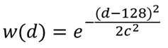
아래 수학식 4는 타겟 뷰에 인접한 뷰를 구성하는 서브 뷰의 거리에 따라 가중치를 부여하는 식을 나타낸다. Equation (4) below expresses an expression for giving a weight according to the distance of the sub-view constituting the view adjacent to the target view.

여기서, |x|는 휘도 값을 조정할 서브 뷰의 개수, c는 평균 분산, m은 하나의 뷰에 대한 서브 뷰의 개수를 나타낸다. 이 경우, c는 사용자에 의해 기정의된 값이 될 수 있다. Where | x | is the number of subviews for which the luminance value is to be adjusted, c is the average variance, and m is the number of subviews for one view. In this case, c may be a predetermined value by the user.
한편, 아래 수학식 5는 디스패리티의 크기에 따라 가중치를 부여하는 식을 나타낸다. Equation (5) below expresses a weighting value according to the size of the disparity.
여기서, d는 디스패리티 값(0 ≤ d ≤ 255), c는 평균 분산값을 나타낸다. 이 경우, c는 사용자에 의해 기정의된 값이 될 수 있다.Here, d represents a disparity value (0? D? 255), and c represents an average variance value. In this case, c may be a predetermined value by the user.
도 9는 본 발명의 일 실시 예에 따른 디스플레이 장치의 제어 방법을 설명하기 위한 흐름도이다.9 is a flowchart illustrating a method of controlling a display device according to an embodiment of the present invention.
도 9에 도시된 다시점 영상 디스플레이 장치의 제어 방법에 따르면, 우선, 멀티 뷰 중 제1 및 제2 타겟 뷰를 선택하여 사용자의 좌안 및 우안 영상으로 제공한다(S910).According to the control method of the multi-view image display apparatus shown in FIG. 9, first and second target views of the multi-view are selected and provided as the left and right eye images of the user (S910).
이어서, 사용자 위치 이동에 따른 사용자의 얼굴 위치를 추적한다(S920).Then, the face position of the user in accordance with the movement of the user position is tracked (S920).
이후, 추적된 사용자의 얼굴 위치를 기초로 제1 및 제2 타겟 뷰가 좌안 및 우안 영상으로 제공되도록 멀티 뷰의 위치를 시프트시켜 제공한다(S930).Then, the multiview position is shifted so that the first and second target views are provided as the left and right eye images based on the tracked user's face position (S930).
여기서, 다시점 영상 디스플레이 장치는, 서로 다른 시점의 복수의 이미지가 순차적으로 반복 배치되는 디스플레이 패널 및 디스플레이 패널의 전면에 배치되어 시청 영역 별로 상이한 시점의 멀티 뷰를 제공하는 시역 분리부를 포함할 수 있다. Here, the multi-view image display apparatus may include a display panel in which a plurality of images at different points in time are sequentially and repeatedly arranged, and a field-of-view separating unit disposed in front of the display panel to provide multi- .
또한, S910 단계에서는, 멀티 뷰 중 선택된 제1 타켓 뷰와 동일한 방향에 위치하는 나머지 뷰를 제1 타겟 뷰로 대체하고, 멀티 뷰 중 선택된 제2 타겟 뷰와 동일한 방향에 위치하는 나머지 뷰를 제2 타겟 뷰로 대체하여 제공할 수 있다. In step S910, the remaining target positioned in the same direction as the first target view selected in the multi-view is replaced with the first target view, and the remaining view positioned in the same direction as the selected second target view in the multi- View. ≪ / RTI >
또한, S910 단계에서는, 디스플레이 패널에 반복 배치되는 복수의 이미지 중 선택된 제1 타겟 이미지로 제1 타겟 뷰 및 제1 타겟 뷰와 동일한 방향에 위치하는 나머지 타겟 뷰를 구성하는 이미지를 모두 대체하고, 제2 타겟 이미지로 제2 타겟 뷰 및 제2 타겟 뷰와 동일한 방향에 위치하는 나머지 타겟 뷰를 구성하는 이미지를 모두 대체하여 제공할 수 있다. In addition, in step S910, all of the images constituting the first target view and the remaining target views located in the same direction as the first target view are replaced with the selected first target image among the plurality of images repeatedly arranged on the display panel, The second target view with the second target image, and the remaining target view positioned in the same direction as the second target view.
또한, S910 단계에서는, 멀티 뷰 중 선택된 제1 및 제2 타겟 뷰와 각각 인접한 뷰의 휘도를 기설정된 휘도 값 이하로 조정하여 제공할 수 있다. In addition, in step S910, the brightness of the view adjacent to the first and second target views selected in the multi-view may be adjusted to be equal to or less than a preset brightness value.
또한, S910 단계에서는, 멀티 뷰 중 선택된 제1 및 제2 타겟 뷰와 각각 인접한 뷰를 구성하는 복수의 이미지들을 제1 및 제2 타겟 뷰 각각과의 거리에 따른 가중치를 적용한 휘도 값으로 조정하여 제공할 수 있다. In step S910, the plurality of images constituting the views adjacent to the first and second target views selected from among the multi-view images are adjusted by adjusting the brightness values based on the distances between the first and second target views, respectively can do.
또한, S910 단계에서는, 멀티 뷰 중 선택된 제1 및 제2 타겟 뷰를 제외한 나머지 뷰를, 제1 및 제2 타겟 뷰 각각과 동일한 방향에서 제1 및 제2 타겟 뷰 각각과의 거리에 따른 가중치를 적용한 휘도 값으로 조정하여 제공할 수 있다. In step S910, the remaining views excluding the first and second target views selected from among the multi-views are weighted according to distances from the first and second target views in the same direction as the first and second target views, respectively It can be adjusted and supplied to the applied luminance value.
또한, S910 단계에서는, 제1 타겟 뷰와 동일한 방향에 위치하는 나머지 뷰와 제1 타겟 뷰 사이의 거리에 반비례하여 휘도가 감소하도록 나머지 뷰의 휘도를 조정하고, 제2 타겟 뷰와 동일한 방향에 위치하는 나머지 뷰와 제2 타겟 뷰 사이의 거리에 반비례하여 휘도가 감소하도록 나머지 뷰의 휘도를 조정할 수 있다. In step S910, the luminance of the remaining view is adjusted so that the luminance is decreased in inverse proportion to the distance between the remaining view positioned in the same direction as the first target view and the first target view, The luminance of the remaining view can be adjusted so that the luminance decreases in inverse proportion to the distance between the remaining view and the second target view.
이상과 같이 본 발명에 따르면, 무안경 3D 디스플레이의 크로스토크 저감을 통해 3D 입체감을 증가시킬 수 있게 된다. As described above, according to the present invention, the 3D stereoscopic effect can be increased by reducing the crosstalk of the spectacles 3D display.
상술한 다양한 실시 예에 따른 다시점 영상 디스플레이 장치의 제어 방법은 프로그램으로 구현되어 디스플레이 장치에 제공될 수 있다.The control method of the multi-view image display device according to the above-described various embodiments may be implemented as a program and provided to a display device.
일 예로, 멀티 뷰 중 제1 및 제2 타겟 뷰를 선택하여 사용자의 좌안 및 우안 영상으로 제공하는 단계, 사용자 위치 이동에 따른 사용자의 얼굴 위치를 추적하는 단계 및 추적된 사용자의 얼굴 위치를 기초로 제1 및 제2 타겟 뷰가 좌안 및 우안 영상으로 제공되도록 멀티 뷰의 위치를 시프트시켜 제공하는 단계를 수행하는 프로그램이 저장된 비일시적 판독 가능 매체(non-transitory computer readable medium)가 제공될 수 있다.For example, selecting the first and second target views of the multi-view and providing the selected first and second target views as the left and right eye images of the user, tracking the face position of the user according to the user position movement, There may be provided a non-transitory computer readable medium in which the program performing the steps of shifting and providing the position of the multi-view so that the first and second target views are provided as left-eye and right-eye images.
비일시적 판독 가능 매체란 레지스터, 캐쉬, 메모리 등과 같이 짧은 순간 동안 데이터를 저장하는 매체가 아니라 반영구적으로 데이터를 저장하며, 기기에 의해 판독(reading)이 가능한 매체를 의미한다. 구체적으로는, 상술한 다양한 어플리케이션 또는 프로그램들은 CD, DVD, 하드 디스크, 블루레이 디스크, USB, 메모리카드, ROM 등과 같은 비일시적 판독 가능 매체에 저장되어 제공될 수 있다. A non-transitory readable medium is a medium that stores data for a short period of time, such as a register, cache, memory, etc., but semi-permanently stores data and is readable by the apparatus. In particular, the various applications or programs described above may be stored on non-volatile readable media such as CD, DVD, hard disk, Blu-ray disk, USB, memory card, ROM,
또한, 이상에서는 본 발명의 바람직한 실시 예에 대하여 도시하고 설명하였지만, 본 발명은 상술한 특정의 실시 예에 한정되지 아니하며, 청구범위에서 청구하는 본 발명의 요지를 벗어남이 없이 당해 발명이 속하는 기술분야에서 통상의 지식을 가진 자에 의해 다양한 변형실시가 가능한 것은 물론이고, 이러한 변형실시들은 본 발명의 기술적 사상이나 전망으로부터 개별적으로 이해되어져서는 안될 것이다.While the present invention has been particularly shown and described with reference to exemplary embodiments thereof, it is to be understood that the invention is not limited to the disclosed exemplary embodiments, but, on the contrary, It will be understood by those skilled in the art that various changes in form and details may be made therein without departing from the spirit and scope of the present invention.
100 : 디스플레이 장치
110 : 트랙킹부 120 : 디스플레이부
130 : 제어부 100: display device
110: tracking unit 120: display unit
130:
Claims (16)
상이한 시점의 복수의 뷰를 제공하는 디스플레이부;
사용자 위치 이동에 따른 사용자의 얼굴 위치를 추적하는 트랙킹부; 및
추적된 사용자의 얼굴 위치를 기초로 상기 복수의 뷰 중 제1 및 제2 타겟 뷰가 상기 사용자의 좌안 및 우안 영상으로 제공되도록 상기 복수의 뷰의 위치를 시프트시켜 제공하는 제어부;를 포함하며,
상기 복수의 뷰 각각은 복수의 서브 뷰를 포함하며,
상기 제어부는,
상기 복수의 뷰 중 상기 제1 타켓 뷰 방향에 위치하는 나머지 뷰를 구성하는 복수의 서브 뷰 중 적어도 하나의 서브 뷰를 제1 서브 뷰로 대체하고, 상기 제2 타겟 뷰 방향에 위치하는 나머지 뷰를 구성하는 복수의 서브 뷰 중 적어도 하나의 서브 뷰를 제2 서브 뷰로 대체하여 제공하는 다시점 영상 디스플레이 장치. A multi-view image display apparatus comprising:
A display unit for providing a plurality of views at different viewpoints;
A tracking unit for tracking a face position of the user in accordance with the movement of the user position; And
And a controller for shifting and providing the positions of the plurality of views so that the first and second target views of the plurality of views are provided as the left and right eye images of the user based on the face position of the tracked user,
Each of the plurality of views comprising a plurality of subviews,
Wherein,
At least one subview of the plurality of subviews constituting the remaining view positioned in the first target view direction among the plurality of views is replaced with a first subview and a remaining view located in the second target view direction is constituted View by replacing at least one of the plurality of sub-views with a second sub-view.
상기 디스플레이부는,
서로 다른 시점의 복수의 이미지가 순차적으로 반복 배치되는 디스플레이 패널; 및
상기 디스플레이 패널의 전면에 배치되어 시청 영역 별로 상기 서로 다른 시점에 대응되는 복수의 뷰를 제공하는 시역 분리부;를 포함하는 것을 특징으로 하는 다시점 영상 디스플레이 장치.The method according to claim 1,
The display unit includes:
A display panel in which a plurality of images at different time points are sequentially and repeatedly arranged; And
And a field of view separator disposed on a front surface of the display panel to provide a plurality of views corresponding to the different viewpoints for each viewing area.
상기 제어부는,
상기 제1 타겟 뷰 및 상기 제1 타겟 뷰 방향에 위치하는 나머지 뷰를 구성하는 복수의 서브 뷰를 상기 제1 서브 뷰로 모두 대체하고, 상기 제2 타겟 뷰 및 상기 제2 타겟 뷰 방향에 위치하는 나머지 뷰를 구성하는 복수의 서브 뷰를 모두 상기 제2 서브 뷰로 대체하는 다시점 영상 디스플레이 장치. The method according to claim 1,
Wherein,
The first sub view and the second sub view, the first sub view and the second sub view, the subviews constituting the first target view and the remaining views located in the first target view direction are all replaced with the first subview, And replaces all of the plurality of subviews constituting the view with the second subview.
상기 제어부는,
상기 복수의 뷰 각각을 구성하는 복수의 서브 뷰 중 상기 제1 및 제2 타겟 뷰 각각과 인접한 기설정된 개수의 서브 뷰의 휘도를 기설정된 휘도 값 이하로 조정하여 제공하는 것을 특징으로 하는 다시점 영상 디스플레이 장치. The method according to claim 1,
Wherein,
Wherein a brightness of a predetermined number of subviews adjacent to each of the first and second target views among the plurality of subviews constituting each of the plurality of views is adjusted to be equal to or less than a preset brightness value, Display device.
상기 제어부는,
상기 제1 및 제2 타겟 뷰 각각과 인접한 기설정된 개수의 서브 뷰의 휘도를상기 제1 및 제2 타겟 뷰 각각과의 거리에 따른 가중치를 적용한 휘도 값으로 조정하여 제공하는 것을 특징으로 하는 다시점 영상 디스플레이 장치. 6. The method of claim 5,
Wherein,
And adjusts the brightness of a predetermined number of sub-views adjacent to each of the first and second target views to a brightness value to which a weight is applied according to a distance between each of the first and second target views. A video display device.
상기 제어부는,
상기 복수의 뷰 중 선택된 상기 제1 및 제2 타겟 뷰를 제외한 나머지 뷰를, 상기 제1 및 제2 타겟 뷰 각각과 동일한 방향에서 상기 제1 및 제2 타겟 뷰 각각과의 거리에 따른 가중치를 적용한 휘도 값으로 조정하여 제공하는 것을 특징으로 하는 다시점 영상 디스플레이 장치. The method according to claim 1,
Wherein,
Wherein the first and second target views are selected from the plurality of views and the remaining views except for the first and second target views are weighted according to distances from the first and second target views in the same direction as the first and second target views, And adjusting the brightness value of the second image data.
상기 제1 타겟 뷰와 동일한 방향에 위치하는 나머지 뷰와 상기 제1 타겟 뷰 사이의 거리에 반비례하여 휘도가 감소하도록 상기 나머지 뷰의 휘도를 조정하고, 상기 제2 타겟 뷰와 동일한 방향에 위치하는 나머지 뷰와 상기 제2 타겟 뷰 사이의 거리에 반비례하여 휘도가 감소하도록 상기 나머지 뷰의 휘도를 조정하는 것을 특징으로 하는 다시점 영상 디스플레이 장치. 8. The method of claim 7,
The luminance of the remaining view is adjusted so that the luminance decreases in inverse proportion to the distance between the remaining view positioned in the same direction as the first target view and the first target view, And adjusts the luminance of the remaining view so that the luminance decreases in inverse proportion to the distance between the view and the second target view.
상이한 시점의 복수의 뷰 중 제1 및 제2 타겟 뷰를 사용자의 좌안 및 우안 영상으로 제공하는 단계;
사용자 위치 이동에 따른 사용자의 얼굴 위치를 추적하는 단계; 및
추적된 사용자의 얼굴 위치를 기초로 상기 제1 및 제2 타겟 뷰가 좌안 및 우안 영상으로 제공되도록 상기 복수의 뷰의 위치를 시프트시켜 제공하는 단계;를 포함하며,
상기 복수의 뷰 각각은 복수의 서브 뷰를 포함하며,
상기 복수의 뷰의 위치를 시프트시켜 제공하는 단계는,
상기 복수의 뷰 중 상기 제1 타켓 뷰 방향에 위치하는 나머지 뷰를 구성하는 복수의 서브 뷰 중 적어도 하나의 서브 뷰를 제1 서브 뷰로 대체하고, 상기 제2 타겟 뷰 방향에 위치하는 나머지 뷰를 구성하는 복수의 서브 뷰 중 적어도 하나의 서브 뷰를 제2 서브 뷰로 대체하여 제공하는 제어 방법. A method of controlling a multi-view image display apparatus,
Providing a first and a second one of a plurality of views at different viewpoints as a user's left and right eye images;
Tracking the face position of the user according to the movement of the user position; And
And shifting and providing the positions of the plurality of views such that the first and second target views are provided as left eye and right eye images based on the face position of the tracked user,
Each of the plurality of views comprising a plurality of subviews,
Wherein shifting and providing the positions of the plurality of views comprises:
At least one subview of the plurality of subviews constituting the remaining view positioned in the first target view direction among the plurality of views is replaced with a first subview and a remaining view located in the second target view direction is constituted Wherein at least one of the plurality of subviews is replaced by a second subview.
상기 다시점 영상 디스플레이 장치는,
서로 다른 시점의 복수의 이미지가 순차적으로 반복 배치되는 디스플레이 패널 및, 상기 디스플레이 패널의 전면에 배치되어 시청 영역 별로 상기 서로 다른 시점에 대응되는 상기 복수의 뷰를 제공하는 시역 분리부를 포함하는 것을 특징으로 하는 제어 방법.10. The method of claim 9,
The multi-view image display apparatus includes:
A display panel in which a plurality of images at different viewpoints are sequentially and repeatedly arranged; and a field-of-view separation unit disposed in front of the display panel and providing the plurality of views corresponding to the different viewpoints for each viewing area, Lt; / RTI >
상기 사용자의 좌안 및 우안 영상으로 제공하는 단계는,
상기 제1 타겟 뷰 상기 제1 타겟 뷰 방향에 위치하는 나머지 뷰를 구성하는 복수의 서브 뷰를 상기 제1 서브 뷰로 모두 대체하고, 상기 제2 타겟 뷰 및 상기 제2 타겟 뷰 방향에 위치하는 나머지 뷰를 구성하는 복수의 서브 뷰를 모두 상기 제2 서브 뷰로 대체하는 것을 특징으로 하는 제어 방법. 10. The method of claim 9,
Wherein the providing of the left eye and right eye images of the user comprises:
The first target view and the subviews constituting the remaining views located in the first target view direction are all replaced with the first subview and the remaining views located in the second target view and the second target view direction View is replaced with the second sub-view.
상기 사용자의 좌안 및 우안 영상으로 제공하는 단계는,
상기 복수의 뷰 각각을 구성하는 복수의 서브 뷰 중 상기 제1 및 제2 타겟 뷰 각각과 인접한 기설정된 개수의 서브 뷰의 휘도를 기설정된 휘도 값 이하로 조정하여 제공하는 것을 특징으로 하는 제어 방법.10. The method of claim 9,
Wherein the providing of the left eye and right eye images of the user comprises:
Wherein a brightness of a predetermined number of subviews adjacent to each of the first and second target views among the plurality of subviews constituting each of the plurality of views is adjusted to be equal to or less than a preset brightness value.
상기 사용자의 좌안 및 우안 영상으로 제공하는 단계는,
상기 제1 및 제2 타겟 뷰 각각과 인접한 기설정된 개수의 서브 뷰의 휘도를상기 제1 및 제2 타겟 뷰 각각과의 거리에 따른 가중치를 적용한 휘도 값으로 조정하여 제공하는 것을 특징으로 하는 제어 방법.14. The method of claim 13,
Wherein the providing of the left eye and right eye images of the user comprises:
The brightness of a predetermined number of subviews adjacent to each of the first and second target views is adjusted to a brightness value to which a weight is applied according to a distance between the first and second target views, .
상기 사용자의 좌안 및 우안 영상으로 제공하는 단계는,
상기 복수의 뷰 중 선택된 상기 제1 및 제2 타겟 뷰를 제외한 나머지 뷰를, 상기 제1 및 제2 타겟 뷰 각각과 동일한 방향에서 상기 제1 및 제2 타겟 뷰 각각과의 거리에 따른 가중치를 적용한 휘도 값으로 조정하여 제공하는 것을 특징으로 하는 제어 방법. 10. The method of claim 9,
Wherein the providing of the left eye and right eye images of the user comprises:
Wherein the first and second target views are selected from the plurality of views and the remaining views except for the first and second target views are weighted according to distances from the first and second target views in the same direction as the first and second target views, And adjusting it to a luminance value.
상기 사용자의 좌안 및 우안 영상으로 제공하는 단계는,
상기 제1 타겟 뷰와 동일한 방향에 위치하는 나머지 뷰와 상기 제1 타겟 뷰 사이의 거리에 반비례하여 휘도가 감소하도록 상기 나머지 뷰의 휘도를 조정하고, 상기 제2 타겟 뷰와 동일한 방향에 위치하는 나머지 뷰와 상기 제2 타겟 뷰 사이의 거리에 반비례하여 휘도가 감소하도록 상기 나머지 뷰의 휘도를 조정하는 것을 특징으로 하는 제어 방법. 16. The method of claim 15,
Wherein the providing of the left eye and right eye images of the user comprises:
The luminance of the remaining view is adjusted so that the luminance decreases in inverse proportion to the distance between the remaining view positioned in the same direction as the first target view and the first target view, And adjusts the luminance of the remaining view so that the luminance decreases in inverse proportion to the distance between the view and the second target view.
Priority Applications (8)
| Application Number | Priority Date | Filing Date | Title |
|---|---|---|---|
| KR1020130111058A KR101856568B1 (en) | 2013-09-16 | 2013-09-16 | Multi view image display apparatus and controlling method thereof |
| US14/171,861 US9088790B2 (en) | 2013-09-16 | 2014-02-04 | Display device and method of controlling the same |
| PCT/KR2014/001192 WO2015037796A1 (en) | 2013-09-16 | 2014-02-13 | Display device and method of controlling the same |
| BR112016005219-6A BR112016005219B1 (en) | 2013-09-16 | 2014-02-13 | MULTIPLE VIEWPOINT IMAGE DISPLAY DEVICE, AND METHOD OF CONTROLLING A MULTIPLE VIEWPOINT IMAGE DISPLAY DEVICE |
| CA2924030A CA2924030C (en) | 2013-09-16 | 2014-02-13 | Display device and method of controlling the same |
| MX2016003357A MX353699B (en) | 2013-09-16 | 2014-02-13 | Display device and method of controlling the same. |
| EP14156330.4A EP2849443A1 (en) | 2013-09-16 | 2014-02-24 | Display device and method of controlling the same |
| CN201410213227.4A CN104469341B (en) | 2013-09-16 | 2014-05-20 | Display device and its control method |
Applications Claiming Priority (1)
| Application Number | Priority Date | Filing Date | Title |
|---|---|---|---|
| KR1020130111058A KR101856568B1 (en) | 2013-09-16 | 2013-09-16 | Multi view image display apparatus and controlling method thereof |
Publications (2)
| Publication Number | Publication Date |
|---|---|
| KR20150031626A KR20150031626A (en) | 2015-03-25 |
| KR101856568B1 true KR101856568B1 (en) | 2018-06-19 |
Family
ID=50179484
Family Applications (1)
| Application Number | Title | Priority Date | Filing Date |
|---|---|---|---|
| KR1020130111058A Active KR101856568B1 (en) | 2013-09-16 | 2013-09-16 | Multi view image display apparatus and controlling method thereof |
Country Status (8)
| Country | Link |
|---|---|
| US (1) | US9088790B2 (en) |
| EP (1) | EP2849443A1 (en) |
| KR (1) | KR101856568B1 (en) |
| CN (1) | CN104469341B (en) |
| BR (1) | BR112016005219B1 (en) |
| CA (1) | CA2924030C (en) |
| MX (1) | MX353699B (en) |
| WO (1) | WO2015037796A1 (en) |
Families Citing this family (29)
| Publication number | Priority date | Publication date | Assignee | Title |
|---|---|---|---|---|
| US9716877B2 (en) * | 2010-10-01 | 2017-07-25 | Samsung Electronics Co., Ltd. | 3D display device using barrier and driving method thereof |
| JP5367846B2 (en) * | 2011-08-24 | 2013-12-11 | 株式会社東芝 | Image processing apparatus, method and program, and stereoscopic image display apparatus |
| JP6359990B2 (en) * | 2015-02-24 | 2018-07-18 | 株式会社ジャパンディスプレイ | Display device and display method |
| RU2596062C1 (en) | 2015-03-20 | 2016-08-27 | Автономная Некоммерческая Образовательная Организация Высшего Профессионального Образования "Сколковский Институт Науки И Технологий" | Method for correction of eye image using machine learning and method of machine learning |
| EP3345036B1 (en) * | 2015-09-05 | 2021-12-15 | LEIA Inc. | Multibeam diffraction grating-based display with head tracking |
| KR102143463B1 (en) * | 2015-09-24 | 2020-08-12 | 삼성전자주식회사 | Multi view image display apparatus and contorl method thereof |
| KR102444311B1 (en) * | 2015-10-26 | 2022-09-16 | 엘지디스플레이 주식회사 | Glasses-free stereoscopic image display device and driving method thereof |
| CN114143495B (en) | 2016-01-05 | 2025-07-15 | 瑞尔D斯帕克有限责任公司 | Gaze Correction for Multi-View Images |
| EP3408699B1 (en) | 2016-01-30 | 2023-10-11 | LEIA Inc. | Multibeam element-based backlighting having converging views |
| CN108307185B (en) * | 2016-08-09 | 2024-01-12 | 擎中科技(上海)有限公司 | Naked eye 3D display device and display method thereof |
| KR102608466B1 (en) * | 2016-11-22 | 2023-12-01 | 삼성전자주식회사 | Method and apparatus for processing image |
| CN107249125A (en) * | 2017-06-22 | 2017-10-13 | 上海玮舟微电子科技有限公司 | A kind of bore hole 3D display methods and device |
| EP4293574A3 (en) | 2017-08-08 | 2024-04-03 | RealD Spark, LLC | Adjusting a digital representation of a head region |
| CN108234990B (en) * | 2018-02-12 | 2021-04-20 | 苏州佳世达电通有限公司 | Stereoscopic display device and stereoscopic display method |
| US11017575B2 (en) | 2018-02-26 | 2021-05-25 | Reald Spark, Llc | Method and system for generating data to provide an animated visual representation |
| EP3837579B1 (en) * | 2018-08-13 | 2024-05-22 | LEIA Inc. | Grating collimator, backlight system, and method employing a light-recycling light source |
| KR20210037005A (en) * | 2018-08-26 | 2021-04-05 | 레이아 인코포레이티드 | Multi-view displays, systems and methods with user tracking |
| US10854171B2 (en) * | 2018-12-31 | 2020-12-01 | Samsung Electronics Co., Ltd. | Multi-user personal display system and applications thereof |
| CN113728269B (en) * | 2019-04-02 | 2024-05-28 | 镭亚股份有限公司 | Multi-view display alignment method and system |
| US12212734B2 (en) * | 2019-06-27 | 2025-01-28 | Texas Instruments Incorporated | Methods and apparatus to render 3D content within a moveable region of display screen |
| US11750795B2 (en) | 2020-05-12 | 2023-09-05 | Apple Inc. | Displays with viewer tracking |
| WO2022150323A1 (en) * | 2021-01-11 | 2022-07-14 | Perdix Systems Llc | Displays with selective pixel brightness tuning |
| WO2022216459A1 (en) * | 2021-04-08 | 2022-10-13 | Rankor Industrial Llc | Displays with viewer tracking for vertical parallax correction |
| WO2023092595A1 (en) * | 2021-11-29 | 2023-06-01 | 京东方科技集团股份有限公司 | Method and apparatus for processing three-dimensional image data, and device and medium |
| US20240236291A1 (en) * | 2021-12-29 | 2024-07-11 | Beijing Boe Display Technology Co., Ltd. | Method and apparatus for displaying multi-viewpoint video, displaying device, medium and program |
| EP4270946A1 (en) | 2022-02-18 | 2023-11-01 | Innolux Corporation | Display device with three-dimensional image display function and three-dimensional image display method |
| WO2023219638A1 (en) * | 2022-05-10 | 2023-11-16 | Leia Inc. | Head-tracking multiview display and method |
| US12294692B2 (en) * | 2022-06-23 | 2025-05-06 | Apple Inc. | Displays with viewer tracking for vertical parallax correction |
| KR20240144549A (en) * | 2023-03-23 | 2024-10-02 | 삼성디스플레이 주식회사 | Display device and driving method thereof |
Citations (2)
| Publication number | Priority date | Publication date | Assignee | Title |
|---|---|---|---|---|
| WO2009095862A1 (en) * | 2008-02-01 | 2009-08-06 | Koninklijke Philips Electronics N.V. | Autostereoscopic display device |
| JP2012249060A (en) * | 2011-05-27 | 2012-12-13 | Jvc Kenwood Corp | Autostereoscopic display device |
Family Cites Families (56)
| Publication number | Priority date | Publication date | Assignee | Title |
|---|---|---|---|---|
| KR100506845B1 (en) * | 2002-02-14 | 2005-08-08 | 엘지전자 주식회사 | Method for editing a multi-view stream in optical disc device |
| US7245430B2 (en) * | 2003-04-21 | 2007-07-17 | Ricoh Company, Ltd. | Method and apparatus for displaying three-dimensional stereo image using light deflector |
| EP1842179A1 (en) * | 2005-01-18 | 2007-10-10 | Koninklijke Philips Electronics N.V. | Multi-view display device |
| KR100940018B1 (en) * | 2005-09-06 | 2010-02-03 | 후지쓰 텐 가부시키가이샤 | Display device and display method |
| EP1967017B1 (en) * | 2005-12-20 | 2019-12-04 | Koninklijke Philips N.V. | Autostereoscopic display device |
| WO2008020399A1 (en) * | 2006-08-17 | 2008-02-21 | Koninklijke Philips Electronics N.V. | Display device |
| RU2377623C2 (en) * | 2007-04-20 | 2009-12-27 | Василий Александрович ЕЖОВ | Method of viewing stereo images with complete resolution for each aspect and device to this end |
| US8194119B2 (en) * | 2007-05-10 | 2012-06-05 | Chroma3D Systems, Inc. | Display of generalized anaglyphs without retinal rivalry |
| EP2063647A1 (en) * | 2007-11-24 | 2009-05-27 | Barco NV | Calibration of a 3-dimensional display |
| US20090282429A1 (en) | 2008-05-07 | 2009-11-12 | Sony Ericsson Mobile Communications Ab | Viewer tracking for displaying three dimensional views |
| US8456516B2 (en) * | 2008-07-01 | 2013-06-04 | Barco N.V. | Methods and systems for stereoscopic imaging |
| KR101502419B1 (en) * | 2008-07-11 | 2015-03-13 | 삼성디스플레이 주식회사 | Multi-view video display method, display device for performing the same |
| KR20100013902A (en) * | 2008-08-01 | 2010-02-10 | 삼성전자주식회사 | Display device |
| US20100060667A1 (en) * | 2008-09-10 | 2010-03-11 | Apple Inc. | Angularly dependent display optimized for multiple viewing angles |
| US20110255159A1 (en) * | 2008-12-22 | 2011-10-20 | Koninklijke Philips Electronics N.V. | Autostereoscopic display device |
| WO2011036761A1 (en) * | 2009-09-25 | 2011-03-31 | 株式会社東芝 | Multi-view image generation method and device |
| KR20110041753A (en) | 2009-10-16 | 2011-04-22 | 삼성전자주식회사 | Point-to-Point Crosstalk Reduction Device and Method |
| KR20110045654A (en) | 2009-10-27 | 2011-05-04 | 삼성전자주식회사 | Crosstalk user tracking stereoscopic display device and method |
| TWI407195B (en) * | 2009-12-30 | 2013-09-01 | Unique Instr Co Ltd | A full-screen three-dimensional image display device |
| US8964013B2 (en) * | 2009-12-31 | 2015-02-24 | Broadcom Corporation | Display with elastic light manipulator |
| JP5296225B2 (en) | 2010-01-13 | 2013-09-25 | 株式会社東芝 | 3D image display device |
| KR20110088334A (en) * | 2010-01-28 | 2011-08-03 | 삼성전자주식회사 | Method and apparatus for generating data stream for providing 3D multimedia service, Method and apparatus for receiving data stream for providing 3D multimedia service |
| US20110199463A1 (en) * | 2010-02-15 | 2011-08-18 | Gallagher Andrew C | Display with integrated camera |
| US20110199469A1 (en) * | 2010-02-15 | 2011-08-18 | Gallagher Andrew C | Detection and display of stereo images |
| US8687051B2 (en) * | 2010-03-03 | 2014-04-01 | Fraunhofer-Gesellschaft Zur Foerderung Der Angewandten Forschung E.V. | Screen and method for representing picture information |
| WO2011123174A1 (en) * | 2010-04-01 | 2011-10-06 | Thomson Licensing | Disparity value indications |
| US10089937B2 (en) * | 2010-06-21 | 2018-10-02 | Microsoft Technology Licensing, Llc | Spatial and temporal multiplexing display |
| KR20120010404A (en) | 2010-07-26 | 2012-02-03 | 삼성전자주식회사 | Multiview Display System and Method Using Color-Maintaining Selective Subpixel Rendering |
| KR101330412B1 (en) * | 2010-08-23 | 2013-11-15 | 엘지디스플레이 주식회사 | 3d image display device and driving method thereof |
| US20130147797A1 (en) * | 2010-08-30 | 2013-06-13 | Sharp Kabushiki Kaisha | Three-dimensional image generating method, three-dimensional image generating apparatus, and display apparatus provided with same |
| US9716877B2 (en) | 2010-10-01 | 2017-07-25 | Samsung Electronics Co., Ltd. | 3D display device using barrier and driving method thereof |
| US8860785B2 (en) * | 2010-12-17 | 2014-10-14 | Microsoft Corporation | Stereo 3D video support in computing devices |
| WO2012085163A1 (en) * | 2010-12-21 | 2012-06-28 | Barco N.V. | Method and system for improving the visibility of features of an image |
| CN103348682B (en) * | 2010-12-29 | 2016-10-26 | 汤姆逊许可公司 | Method and apparatus for providing monoscopic vision in a multiview system |
| KR101088634B1 (en) * | 2011-04-11 | 2011-12-06 | 이종오 | Stereoscopic display panel, stereoscopic display device and stereoscopic display method |
| JP5908894B2 (en) * | 2011-04-28 | 2016-04-26 | パナソニック株式会社 | Recording medium, reproducing apparatus, and recording apparatus |
| JPWO2012176431A1 (en) * | 2011-06-20 | 2015-02-23 | パナソニック株式会社 | Multi-viewpoint image generation apparatus and multi-viewpoint image generation method |
| WO2013001165A1 (en) * | 2011-06-28 | 2013-01-03 | Nokia Corporation | A method, a system, a viewing device and a computer program for picture rendering |
| KR101853064B1 (en) | 2011-07-14 | 2018-04-30 | 에스케이플래닛 주식회사 | Three dimensional display apparatus and method thereof |
| US9264689B2 (en) * | 2011-08-04 | 2016-02-16 | Semiconductor Components Industries, Llc | Systems and methods for color compensation in multi-view video |
| JP5367846B2 (en) | 2011-08-24 | 2013-12-11 | 株式会社東芝 | Image processing apparatus, method and program, and stereoscopic image display apparatus |
| JP5367034B2 (en) | 2011-08-24 | 2013-12-11 | 株式会社ソニー・コンピュータエンタテインメント | Image processing apparatus and image processing method |
| US9191646B2 (en) * | 2011-08-29 | 2015-11-17 | Nokia Technologies Oy | Apparatus, a method and a computer program for video coding and decoding |
| US9414049B2 (en) | 2011-09-19 | 2016-08-09 | Écrans Polaires Inc./Polar Screens Inc. | Method and display for showing a stereoscopic image |
| CN102510504B (en) | 2011-09-27 | 2015-04-15 | 深圳超多维光电子有限公司 | Display range determination and display method and device for naked eye stereo display system |
| KR101888082B1 (en) | 2011-09-27 | 2018-09-10 | 엘지전자 주식회사 | Image display apparatus, and method for operating the same |
| KR101960844B1 (en) | 2011-11-01 | 2019-03-22 | 삼성전자주식회사 | Image processing apparatus and method |
| KR101863626B1 (en) | 2011-11-02 | 2018-07-06 | 삼성전자주식회사 | Image processing apparatus and method |
| KR101322910B1 (en) * | 2011-12-23 | 2013-10-29 | 한국과학기술연구원 | Apparatus for 3-dimensional displaying using dyanmic viewing zone enlargement for multiple observers and method thereof |
| KR20130074383A (en) * | 2011-12-26 | 2013-07-04 | 삼성전자주식회사 | Method and apparatus for view generation using multi-layer representation |
| US9392251B2 (en) * | 2011-12-29 | 2016-07-12 | Samsung Electronics Co., Ltd. | Display apparatus, glasses apparatus and method for controlling depth |
| CN202995143U (en) * | 2011-12-29 | 2013-06-12 | 三星电子株式会社 | Glasses device and display device |
| RU2607282C2 (en) | 2012-01-06 | 2017-01-10 | Ултра-Д Коператиф У.А. | Display processor for 3d display |
| KR20140007708A (en) * | 2012-07-10 | 2014-01-20 | 삼성전자주식회사 | Image display apparatus, image display method and glass apparatus |
| US9509970B2 (en) * | 2012-07-18 | 2016-11-29 | Qualcomm Incorporated | Crosstalk reduction with location-based adjustment in multiview video processing |
| KR20140039649A (en) * | 2012-09-24 | 2014-04-02 | 삼성전자주식회사 | Multi view image generating method and multi view image display apparatus |
-
2013
- 2013-09-16 KR KR1020130111058A patent/KR101856568B1/en active Active
-
2014
- 2014-02-04 US US14/171,861 patent/US9088790B2/en active Active
- 2014-02-13 BR BR112016005219-6A patent/BR112016005219B1/en active IP Right Grant
- 2014-02-13 MX MX2016003357A patent/MX353699B/en active IP Right Grant
- 2014-02-13 CA CA2924030A patent/CA2924030C/en active Active
- 2014-02-13 WO PCT/KR2014/001192 patent/WO2015037796A1/en not_active Ceased
- 2014-02-24 EP EP14156330.4A patent/EP2849443A1/en not_active Ceased
- 2014-05-20 CN CN201410213227.4A patent/CN104469341B/en not_active Expired - Fee Related
Patent Citations (2)
| Publication number | Priority date | Publication date | Assignee | Title |
|---|---|---|---|---|
| WO2009095862A1 (en) * | 2008-02-01 | 2009-08-06 | Koninklijke Philips Electronics N.V. | Autostereoscopic display device |
| JP2012249060A (en) * | 2011-05-27 | 2012-12-13 | Jvc Kenwood Corp | Autostereoscopic display device |
Also Published As
| Publication number | Publication date |
|---|---|
| EP2849443A1 (en) | 2015-03-18 |
| CA2924030A1 (en) | 2015-03-19 |
| CA2924030C (en) | 2021-05-18 |
| KR20150031626A (en) | 2015-03-25 |
| US9088790B2 (en) | 2015-07-21 |
| US20150077526A1 (en) | 2015-03-19 |
| CN104469341A (en) | 2015-03-25 |
| MX353699B (en) | 2018-01-25 |
| BR112016005219B1 (en) | 2023-04-25 |
| WO2015037796A1 (en) | 2015-03-19 |
| CN104469341B (en) | 2018-03-09 |
| MX2016003357A (en) | 2016-06-24 |
| BR112016005219A2 (en) | 2017-08-01 |
Similar Documents
| Publication | Publication Date | Title |
|---|---|---|
| KR101856568B1 (en) | Multi view image display apparatus and controlling method thereof | |
| KR102140080B1 (en) | Multi view image display apparatus and controlling method thereof | |
| KR102030830B1 (en) | Curved multiview image display apparatus and control method thereof | |
| KR102185130B1 (en) | Multi view image display apparatus and contorl method thereof | |
| KR102121389B1 (en) | Glassless 3d display apparatus and contorl method thereof | |
| KR101966152B1 (en) | Multi view image display apparatus and contorl method thereof | |
| KR102174258B1 (en) | Glassless 3d display apparatus and contorl method thereof | |
| JP6377155B2 (en) | Multi-view video processing apparatus and video processing method thereof | |
| KR101975246B1 (en) | Multi view image display apparatus and contorl method thereof | |
| KR20140137971A (en) | display apparatus and method for displaying multi view image using the same | |
| KR20150055322A (en) | multi view image display apparatus and multi view image display method thereof | |
| KR20170029210A (en) | Multi view image display apparatus and contorl method thereof | |
| KR101957243B1 (en) | Multi view image display apparatus and multi view image display method thereof | |
| KR102208308B1 (en) | Dispaly apparatus and controlling method thereof | |
| KR101980275B1 (en) | Multi view image display apparatus and display method thereof | |
| KR102143463B1 (en) | Multi view image display apparatus and contorl method thereof | |
| KR20130123693A (en) | An apparatus for processing autostereoscopic image |
Legal Events
| Date | Code | Title | Description |
|---|---|---|---|
| PA0109 | Patent application |
Patent event code: PA01091R01D Comment text: Patent Application Patent event date: 20130916 |
|
| PG1501 | Laying open of application | ||
| A201 | Request for examination | ||
| PA0201 | Request for examination |
Patent event code: PA02012R01D Patent event date: 20160919 Comment text: Request for Examination of Application Patent event code: PA02011R01I Patent event date: 20130916 Comment text: Patent Application |
|
| E902 | Notification of reason for refusal | ||
| PE0902 | Notice of grounds for rejection |
Comment text: Notification of reason for refusal Patent event date: 20170906 Patent event code: PE09021S01D |
|
| AMND | Amendment | ||
| E601 | Decision to refuse application | ||
| PE0601 | Decision on rejection of patent |
Patent event date: 20180226 Comment text: Decision to Refuse Application Patent event code: PE06012S01D Patent event date: 20170906 Comment text: Notification of reason for refusal Patent event code: PE06011S01I |
|
| AMND | Amendment | ||
| PX0901 | Re-examination |
Patent event code: PX09011S01I Patent event date: 20180226 Comment text: Decision to Refuse Application Patent event code: PX09012R01I Patent event date: 20171106 Comment text: Amendment to Specification, etc. |
|
| PX0701 | Decision of registration after re-examination |
Patent event date: 20180409 Comment text: Decision to Grant Registration Patent event code: PX07013S01D Patent event date: 20180329 Comment text: Amendment to Specification, etc. Patent event code: PX07012R01I Patent event date: 20180226 Comment text: Decision to Refuse Application Patent event code: PX07011S01I Patent event date: 20171106 Comment text: Amendment to Specification, etc. Patent event code: PX07012R01I |
|
| X701 | Decision to grant (after re-examination) | ||
| GRNT | Written decision to grant | ||
| PR0701 | Registration of establishment |
Comment text: Registration of Establishment Patent event date: 20180503 Patent event code: PR07011E01D |
|
| PR1002 | Payment of registration fee |
Payment date: 20180504 End annual number: 3 Start annual number: 1 |
|
| PG1601 | Publication of registration | ||
| PR1001 | Payment of annual fee |
Payment date: 20210429 Start annual number: 4 End annual number: 4 |
|
| PR1001 | Payment of annual fee |
Payment date: 20220428 Start annual number: 5 End annual number: 5 |
|
| PR1001 | Payment of annual fee |
Payment date: 20250429 Start annual number: 8 End annual number: 8 |