JP7036080B2 - Inertial navigation system - Google Patents
Inertial navigation system Download PDFInfo
- Publication number
- JP7036080B2 JP7036080B2 JP2019070877A JP2019070877A JP7036080B2 JP 7036080 B2 JP7036080 B2 JP 7036080B2 JP 2019070877 A JP2019070877 A JP 2019070877A JP 2019070877 A JP2019070877 A JP 2019070877A JP 7036080 B2 JP7036080 B2 JP 7036080B2
- Authority
- JP
- Japan
- Prior art keywords
- vehicle
- speed
- angle
- unit
- acceleration
- Prior art date
- Legal status (The legal status is an assumption and is not a legal conclusion. Google has not performed a legal analysis and makes no representation as to the accuracy of the status listed.)
- Active
Links
Images


Classifications
-
- G—PHYSICS
- G01—MEASURING; TESTING
- G01C—MEASURING DISTANCES, LEVELS OR BEARINGS; SURVEYING; NAVIGATION; GYROSCOPIC INSTRUMENTS; PHOTOGRAMMETRY OR VIDEOGRAMMETRY
- G01C21/00—Navigation; Navigational instruments not provided for in groups G01C1/00 - G01C19/00
- G01C21/10—Navigation; Navigational instruments not provided for in groups G01C1/00 - G01C19/00 by using measurements of speed or acceleration
- G01C21/12—Navigation; Navigational instruments not provided for in groups G01C1/00 - G01C19/00 by using measurements of speed or acceleration executed aboard the object being navigated; Dead reckoning
- G01C21/16—Navigation; Navigational instruments not provided for in groups G01C1/00 - G01C19/00 by using measurements of speed or acceleration executed aboard the object being navigated; Dead reckoning by integrating acceleration or speed, i.e. inertial navigation
- G01C21/165—Navigation; Navigational instruments not provided for in groups G01C1/00 - G01C19/00 by using measurements of speed or acceleration executed aboard the object being navigated; Dead reckoning by integrating acceleration or speed, i.e. inertial navigation combined with non-inertial navigation instruments
-
- B—PERFORMING OPERATIONS; TRANSPORTING
- B60—VEHICLES IN GENERAL
- B60W—CONJOINT CONTROL OF VEHICLE SUB-UNITS OF DIFFERENT TYPE OR DIFFERENT FUNCTION; CONTROL SYSTEMS SPECIALLY ADAPTED FOR HYBRID VEHICLES; ROAD VEHICLE DRIVE CONTROL SYSTEMS FOR PURPOSES NOT RELATED TO THE CONTROL OF A PARTICULAR SUB-UNIT
- B60W30/00—Purposes of road vehicle drive control systems not related to the control of a particular sub-unit, e.g. of systems using conjoint control of vehicle sub-units
- B60W30/02—Control of vehicle driving stability
- B60W30/04—Control of vehicle driving stability related to roll-over prevention
-
- B—PERFORMING OPERATIONS; TRANSPORTING
- B60—VEHICLES IN GENERAL
- B60W—CONJOINT CONTROL OF VEHICLE SUB-UNITS OF DIFFERENT TYPE OR DIFFERENT FUNCTION; CONTROL SYSTEMS SPECIALLY ADAPTED FOR HYBRID VEHICLES; ROAD VEHICLE DRIVE CONTROL SYSTEMS FOR PURPOSES NOT RELATED TO THE CONTROL OF A PARTICULAR SUB-UNIT
- B60W40/00—Estimation or calculation of non-directly measurable driving parameters for road vehicle drive control systems not related to the control of a particular sub unit, e.g. by using mathematical models
- B60W40/02—Estimation or calculation of non-directly measurable driving parameters for road vehicle drive control systems not related to the control of a particular sub unit, e.g. by using mathematical models related to ambient conditions
- B60W40/06—Road conditions
- B60W40/076—Slope angle of the road
-
- G—PHYSICS
- G05—CONTROLLING; REGULATING
- G05D—SYSTEMS FOR CONTROLLING OR REGULATING NON-ELECTRIC VARIABLES
- G05D1/00—Control of position, course, altitude or attitude of land, water, air or space vehicles, e.g. using automatic pilots
- G05D1/02—Control of position or course in two dimensions
- G05D1/021—Control of position or course in two dimensions specially adapted to land vehicles
- G05D1/0268—Control of position or course in two dimensions specially adapted to land vehicles using internal positioning means
- G05D1/027—Control of position or course in two dimensions specially adapted to land vehicles using internal positioning means comprising intertial navigation means, e.g. azimuth detector
-
- G—PHYSICS
- G05—CONTROLLING; REGULATING
- G05D—SYSTEMS FOR CONTROLLING OR REGULATING NON-ELECTRIC VARIABLES
- G05D1/00—Control of position, course, altitude or attitude of land, water, air or space vehicles, e.g. using automatic pilots
- G05D1/08—Control of attitude, i.e. control of roll, pitch, or yaw
- G05D1/0891—Control of attitude, i.e. control of roll, pitch, or yaw specially adapted for land vehicles
Landscapes
- Engineering & Computer Science (AREA)
- Radar, Positioning & Navigation (AREA)
- Remote Sensing (AREA)
- Automation & Control Theory (AREA)
- Physics & Mathematics (AREA)
- General Physics & Mathematics (AREA)
- Aviation & Aerospace Engineering (AREA)
- Transportation (AREA)
- Mechanical Engineering (AREA)
- Mathematical Physics (AREA)
- Navigation (AREA)
Description
本発明は、慣性航法装置に係り、特に、自車両の移動量の蓄積に基づいて自車両の位置を推定する慣性航法装置に関する。 The present invention relates to an inertial navigation system, and more particularly to an inertial navigation system that estimates the position of the own vehicle based on the accumulation of the amount of movement of the own vehicle.
車両の姿勢角及び位置に係る情報は、運転支援技術及び予防安全技術にとって最も重要な情報である。例えば、車体のロール角及びピッチ角は、重力加速度成分を補償する制御入力(操舵角、アクセル及びブレーキ)を決定する際に活用でき、より安定した車両の制御が可能になる。さらに、位置推定は車両の位置制御には必要不可欠である。 Information on the attitude angle and position of the vehicle is the most important information for driving assistance technology and preventive safety technology. For example, the roll angle and pitch angle of the vehicle body can be utilized when determining the control input (steering angle, accelerator and brake) for compensating the gravitational acceleration component, and more stable vehicle control becomes possible. Furthermore, position estimation is indispensable for vehicle position control.
特に現在の自動運転技術はGPS(Global Positioning System)又はLIDAR(Laser Imaging Detection and Ranging)等の車両以外の状況(外界状況)を検知する外界センサの情報が自車両の位置を推定する際に必須となっている。そして、かかる外界センサが機能しなくなった際のフェールセーフとして慣性航法(デッドレコニング)が重要な課題となっている。 In particular, the current autonomous driving technology requires information from external sensors such as GPS (Global Positioning System) or LIDAR (Laser Imaging Detection and Ranging) that detect non-vehicle conditions (outside conditions) when estimating the position of the own vehicle. It has become. Inertial navigation (dead reckoning) has become an important issue as a fail-safe when such an external sensor fails.
デッドレコニングは、自車両の位置を直接検出するのではなく、走行時の車両の挙動を示す3軸の角速度(ピッチレート、ロールレート、ヨーレート)と3軸の加速度(前後加速度、横加速度、上下加速度)とが検出可能なIMU(Inertial Measurement Unit:慣性計測装置)、車速センサ及び操舵角センサ等の車両自身の状態を検知する内界センサで検出した自車両の移動の蓄積に基づいて自車両の位置を推定する慣性航法の方式である。 Dead reckoning does not directly detect the position of the own vehicle, but has three axes of angular velocity (pitch rate, roll rate, yaw rate) and three axes of acceleration (front-back acceleration, lateral acceleration, up and down) that indicate the behavior of the vehicle while driving. Based on the accumulation of movement of the own vehicle detected by the internal sensor that detects the state of the vehicle itself such as the IMU (Inertial Measurement Unit) that can detect the acceleration), the vehicle speed sensor, and the steering angle sensor. It is an inertial navigation system that estimates the position of.
外界センサは雨や霧、夜間や逆光といった外界の環境によってその精度が大きく左右される。外界センサからの情報が劣化した場合は、自動運転を中止して運転の主導権を自動運転システムからドライバーに渡す。しかしながら、自動運転システムからドライバーに運転の主導権を渡すまでの間、内界センサのみを用いて自動運転を一定時間継続する事が求められる。 The accuracy of the external sensor is greatly affected by the external environment such as rain, fog, nighttime and backlight. If the information from the external sensor deteriorates, the automatic driving is stopped and the driving initiative is passed from the automatic driving system to the driver. However, it is required to continue the automatic driving for a certain period of time by using only the internal sensor until the driving initiative is handed over from the automatic driving system to the driver.
特許文献1には、GPS、白線認識、周辺環境認識、道路形状及び地図情報に基づいて自車両の位置を推定する自己位置推定装置の発明が開示されている。
特許文献2には、GPSとIMUとの出力差より、各々の誤差量を推定し、自車両の位置および自車両の方位の推定精度を向上させる慣性航法の方法の発明が開示されている。 Patent Document 2 discloses an invention of an inertial navigation method that estimates the amount of each error from the output difference between GPS and IMU and improves the estimation accuracy of the position of the own vehicle and the orientation of the own vehicle.
特許文献3には、GPS衛星から高精度なGPS情報が取得可能な時に車両運動モデルを高精度に推定する装置が示されている。 Patent Document 3 discloses a device that estimates a vehicle motion model with high accuracy when highly accurate GPS information can be acquired from GPS satellites.
しかしながら、特許文献1に記載の発明は、多くの情報の入力を必要としており、入力される情報が一部でも劣化又は欠落すると自己位置推定の精度が低下し、自動運転において自車両を車線内に維持する制御が困難になるおそれがあった。
However, the invention described in
特許文献2に記載の発明は、IMUの誤差推定を高精度で行うには、高精度なGPS情報が必要だが、現在はそのようなサービスは少ないという問題があった。また、使用するIMUは、航空機や船舶に用いられる高精度IMUが想定されており、MEMS(Micro Electro Mechanical Systems)によって量産されたIMUでは同じアルゴリズムを用いても同等の性能が得られず、位置の推定値が不安定になるという問題があった。 The invention described in Patent Document 2 requires highly accurate GPS information in order to perform IMU error estimation with high accuracy, but there is a problem that such services are currently scarce. In addition, the IMU to be used is assumed to be a high-precision IMU used for aircraft and ships, and the IMU mass-produced by MEMS (Micro Electro Mechanical Systems) cannot obtain the same performance even if the same algorithm is used, and the position. There was a problem that the estimated value of was unstable.
特許文献3に記載の発明は、高精度なGPS情報が車両運動モデルの同定には必要で、高精度なGPS情報を取得するために、例えば3つのGPSアンテナを搭載するとコストが嵩むという問題があった。さらにスリップ角を推定する際の基準点について明記されておらず、当該基準点の配置によっては横滑りモデルが破綻するおそれがあった。 The invention described in Patent Document 3 has a problem that high-precision GPS information is necessary for identification of a vehicle motion model, and mounting, for example, three GPS antennas increases the cost in order to acquire high-precision GPS information. there were. Furthermore, the reference point for estimating the slip angle is not specified, and the skid model may break down depending on the arrangement of the reference point.
本発明は、上記問題に鑑みてなされたものであり、外界センサからの情報が途絶した場合に、内界センサで検出した自車両の移動量の蓄積に基づいて自車両の位置を推定する慣性航法装置を実現することを目的とする。 The present invention has been made in view of the above problems, and when the information from the external sensor is interrupted, the inertia for estimating the position of the own vehicle based on the accumulation of the movement amount of the own vehicle detected by the internal sensor. The purpose is to realize a navigation system.
上記目的を達成するために、請求項1に記載の慣性航法装置は、走行時の車両の挙動を示す角速度及び加速度を検出可能な慣性計測装置と、前記車両の前後速度を検出する車速検出部と、前記車両の操舵角を検出する操舵角検出部と、前記車両の上下速度及び横速度を0とみなし、前記慣性計測装置が検出した前記角速度と、前記慣性計測装置が検出した前記加速度と、前記車速検出部が検出した前後速度と、前記車両の方位角の初期値とに基づいて前記車両の姿勢角であるロール角、ピッチ角及び方位角を推定する姿勢角推定部と、前記車両の上下速度を0とみなし、前記姿勢角推定部が推定した姿勢角と、前記慣性計測装置が検出した前記角速度と、前記慣性計測装置が検出した前記加速度と、前記車速検出部が検出した前後速度と、前記操舵角検出部が検出した操舵角と、前記車両の位置の初期値とに基づいて前記車両の現在位置を推定する位置推定部と、を含んでいる。
In order to achieve the above object, the inertial navigation device according to
また、請求項2に記載の慣性航法装置では、前記慣性計測装置は、ピッチレート、ロールレート及びヨーレートの3軸の角速度と、前後加速度、横加速度及び上下加速度の3軸の加速度を検出可能で、前記姿勢角推定部は、前記慣性計測装置が検出したピッチレート、ロールレート及びヨーレートの3軸の角速度と、前記慣性計測装置が検出した前後加速度及び横加速度の2軸の加速度とを用いて前記車両の姿勢角を推定し、前記位置推定部は、前記慣性計測装置が検出した1軸の角速度であるヨーレートと、前記慣性計測装置が検出した2軸の加速度である前後加速度及び横加速度と、姿勢角とを用いて前記車両の現在位置を推定する。 Further, in the inertial navigation device according to claim 2, the inertial measurement device can detect three-axis angular speeds of pitch rate, roll rate and yaw rate, and three-axis accelerations of longitudinal acceleration, lateral acceleration and vertical acceleration. The attitude angle estimation unit uses the three-axis angular speeds of pitch rate, roll rate, and yaw rate detected by the inertial measuring device, and the two-axis accelerations of longitudinal acceleration and lateral acceleration detected by the inertial measuring device. The attitude angle of the vehicle is estimated, and the position estimation unit includes the yaw rate, which is the angular velocity of one axis detected by the inertial measuring device, and the longitudinal acceleration and lateral acceleration, which are the accelerations of the two axes detected by the inertial measuring device. , The posture angle and the current position of the vehicle are estimated.
また、請求項3に記載の慣性航法装置では、前記位置推定部は、前記車両の旋回時の前後速度によらず前記車両の横速度が旋回外方向に生じる位置を基準位置とした横速度を推定する運動方程式を用いて、前記基準位置での加速度と共に前記車両の現在位置を推定する。 Further, in the inertial navigation device according to claim 3, the position estimation unit uses a lateral speed as a reference position based on a position where the lateral speed of the vehicle occurs in the outward turning direction regardless of the front-rear speed when the vehicle turns. Using the estimated equation of motion, the current position of the vehicle is estimated along with the acceleration at the reference position.
また、請求項4に記載の慣性航法装置では、前記基準位置は、前記車両の操舵機能を有しない車輪側の位置である。 Further, in the inertial navigation system according to claim 4, the reference position is a position on the wheel side that does not have the steering function of the vehicle.
また、請求項5に記載の慣性航法装置では、前記基準位置は、前記車両の操舵機能を有しない車輪の車軸の車幅方向の中心である。 Further, in the inertial navigation system according to claim 5, the reference position is the center of the axle of the wheel having no steering function of the vehicle in the vehicle width direction.
また、請求項6に記載の慣性航法装置では、前記位置推定部は、姿勢角の情報を利用した車両運動モデルにより、路面のバンク角及び路面の前後勾配の影響を考慮して前記車両の横速度を推定する。 Further, in the inertial navigation system according to claim 6, the position estimation unit uses a vehicle motion model using information on the attitude angle to consider the influence of the bank angle of the road surface and the front-rear gradient of the road surface, and the side of the vehicle. Estimate the speed.
また、請求項7に記載の慣性航法装置では、前記姿勢角推定部は、前記慣性計測装置が検出した前記加速度と前記車両の運動との関係を表す式に基づいて、前回推定された、前記車両の姿勢角を含む前記車両の状態量から、次時刻の前記車両の状態量を予測する姿勢角推定用予測部と、予め定められた観測方程式を用いて算出される、前記予測された次時刻の前記車両の状態量に対応する、車両前後速度、前記車両の角速度、及び前記車両の加速度と、それぞれの実測値との差分、及び前回推定された前記車両の状態量に基づいて、前記姿勢角推定用予測部で予測された前記車両の状態量を補正する姿勢角推定用更新部と、を含み、前記位置推定部は、基準位置とした、前記車両の旋回時の前後速度によらず前記車両の横速度が旋回外方向に生じる基準位置を含む、前記加速度と前記車両の運動との関係を表す式と、前記姿勢角推定部で推定された姿勢角とに基づいて、前回推定された、前記車両の位置及び速度、加速度、角速度を含む前記車両の状態量から、次時刻の前記車両の状態量を予測する位置推定用予測部と、予め定められた観測方程式を用いて算出される、前記予測された次時刻の前記車両の状態量に対応する、車両前後速度、前記車両の角速度、及び前記車両の加速度、前記車両の位置と、それぞれの実測値との差分、及び前回推定された前記車両の状態量に基づいて、前記位置推定用予測部で予測された前記車両の状態量を補正する位置推定用更新部と、を含んでいる。 Further, in the inertial navigation device according to claim 7, the attitude angle estimation unit is previously estimated based on an equation expressing the relationship between the acceleration detected by the inertial measuring device and the motion of the vehicle. The predicted next calculated by using a prediction unit for estimating the attitude angle for predicting the state amount of the vehicle at the next time from the state amount of the vehicle including the attitude angle of the vehicle and a predetermined observation equation. Based on the vehicle front-rear speed, the angular velocity of the vehicle, the difference between the acceleration of the vehicle and the measured values of each, and the previously estimated state amount of the vehicle corresponding to the state amount of the vehicle at the time. The position estimation unit includes a posture angle estimation update unit that corrects the state amount of the vehicle predicted by the attitude angle estimation prediction unit, and the position estimation unit is based on the front-rear speed of the vehicle when turning, which is a reference position. Previously estimated based on the equation expressing the relationship between the acceleration and the motion of the vehicle, including the reference position where the lateral velocity of the vehicle occurs in the outward turning direction, and the attitude angle estimated by the attitude angle estimation unit. Calculated using the position estimation prediction unit that predicts the state amount of the vehicle at the next time and the predetermined observation equation from the state amount of the vehicle including the position and speed, acceleration, and angular velocity of the vehicle. The vehicle front-rear speed, the angular velocity of the vehicle, the acceleration of the vehicle, the difference between the position of the vehicle and each measured value, and the previous time, corresponding to the state amount of the vehicle at the predicted next time. It includes a position estimation update unit that corrects the state amount of the vehicle predicted by the position estimation prediction unit based on the estimated state amount of the vehicle.
本発明によれば、外界センサからの情報が途絶した場合に、内界センサで検出した自車両の移動量の蓄積に基づいて自車両の位置を推定することができるという効果を奏する。 According to the present invention, when the information from the outside world sensor is interrupted, the position of the own vehicle can be estimated based on the accumulation of the movement amount of the own vehicle detected by the inside world sensor.
以下、図面を参照して本発明の実施の形態を詳細に説明する。図1に示すように、本実施の形態に係る慣性航法装置10は、後述する演算装置14の演算に必要なデータ及び演算装置14による演算結果を記憶する記憶装置18と、車両が備えたセンシング装置及びGPS等の外界センサによって取得した車両周辺の情報から車両の現在位置及び現在のヨー角(方位角)を算出する位置計測装置20と、位置計測装置20が算出した車両の現在位置及び現在のヨー角、車速センサ24が検出した車両前後速度、IMU26が検出した車両の方位角の偏差及び加速度、並びに操舵角センサが検出した車両の操舵角が入力される入力装置12と、入力装置12から入力された入力データ及び記憶装置18に記憶されたデータに基づいて車両位置の推定の演算を行なうコンピュータ等で構成された演算装置14と、演算装置14で演算された車両の位置等を表示するCRT又はLCD等で構成された表示装置16と、で構成されている。
Hereinafter, embodiments of the present invention will be described in detail with reference to the drawings. As shown in FIG. 1, the
本実施の形態に係る外界センサであるセンシング装置は、一例として、車載カメラ等の撮像装置、LIDAR(Light Detection and Ranging)及びソナーのいずれかである。車載カメラ等の撮像装置を車載のセンシング装置とした場合は、一例として、当該撮像装置で取得した車両周辺の画像情報を解析して道路の白線等を検出する。LIDARを車載のセンシング装置とした場合は、一例として、車両周辺に照射したパルス状のレーザの散乱光から道路の白線等を検出する。ソナーを車載のセンシング装置とした場合は、一例として、アスファルトの路面とペイントされた白線との、超音波の反射率の差を利用して、当該白線を識別する。 The sensing device, which is an external sensor according to the present embodiment, is, for example, an image pickup device such as an in-vehicle camera, LIDAR (Light Detection and Ranging), or sonar. When an image pickup device such as an in-vehicle camera is used as an in-vehicle sensing device, as an example, the image information around the vehicle acquired by the image pickup device is analyzed to detect a white line or the like on the road. When LIDAR is used as an in-vehicle sensing device, as an example, white lines on the road are detected from scattered light of a pulsed laser irradiated around the vehicle. When the sonar is used as an in-vehicle sensing device, as an example, the white line is identified by using the difference in the reflectance of ultrasonic waves between the asphalt road surface and the painted white line.
続いて、車両200の挙動に係る座標系を図2に示したように定義する。地球座標系204は地球平面を基準として重力加速度方向とzeとが平行で、yeが北方向を向いている座標系である。路面座標系206は、zrが車両200の重心を通り路面に垂直な方向に向き、xrは車両進行方向に向いている座標系である。車体座標系208は車体バネ上に固定された座標系で、zvは車体鉛直上方向、xvは車体進行方向を向いている。従って、車両200の前後方向は、車体座標系208のx軸に平行な方向となる。後述するように、本実施の形態では、車体座標系208の基準点を車両200の重心ではなく、車両200の後輪の車軸の車幅方向の中心とする。
Subsequently, the coordinate system related to the behavior of the
また、オイラー姿勢角であるロール角φ、ピッチ角θ及びヨー角ψは、地球座標系204に対して、図2に示したように定義される。例えば、ロール角φはx軸まわりの回転角であり、ピッチ角θは、y軸まわりの回転角であり、ヨー角ψは、z軸まわりの回転角である。また、ロール角φ、ピッチ角θ及びヨー角ψの各々は、右ネジの方向(図2では、各々の矢印方向)の回転で正の値を示す。本実施の形態では、便宜上、後述するヨー角偏差は基準座標系を路面座標系206とし、さらに、本来は地球座標系204に対して定義されるオイラー姿勢角を、車体座標系208に対して、ロール角φv、ピッチ角θv及びヨー角ψvと定義する。以後、単に、ロール角φ、ピッチ角θ及びヨー角ψと記した場合は、基本的に、車体座標系208に対して定義された姿勢角であるとする。
Further, the roll angle φ, the pitch angle θ, and the yaw angle ψ, which are Euler attitude angles, are defined as shown in FIG. 2 with respect to the earth coordinate
図3は、旋回中の車両200の後輪車軸中心202の軌跡を、コーナリングスティフネスCpの大小に対応させて示したものである。車両200の横滑りは、コーナリングスティフネスCpの値によって変化する。例えば、Cpが無限大であると、車両200は旋回時に横滑りを起こさない。しかしながら、旋回時に車両200が横滑りをしないというのは現実にはあり得ない。図3に示したように、現実に横滑りを生じながら車両200が旋回する場合のCpをCprealとすると、CpがCpreal小さくなると横滑りは大きくなり、CpがCprealよりもさらに小さくなると横滑りは極めて大きくなる。
FIG. 3 shows the locus of the rear
また、図3に示した横滑りモデルは、一例として、車両200の後輪車軸の車幅方向の中心202(以下、「後輪車軸中心202」と略記)を車両200の横滑り推定の基準点としている。
Further, in the skid model shown in FIG. 3, as an example, the
従来は、位置推定を行う際に必要になる横速度推定について、車両重心位置を基準とした車両運動モデルで横速度推定が数多く行われてきた。しかしながら、車両重心位置を基準にすると、旋回方向が同じでも横滑りの方向が車速(前後速度)によって変化してしまい、横滑りを考慮しない場合よりも位置推定が劣化してしまうおそれがあった。 Conventionally, as for the lateral speed estimation required for position estimation, many lateral speed estimations have been performed using a vehicle motion model based on the position of the center of gravity of the vehicle. However, when the position of the center of gravity of the vehicle is used as a reference, the direction of skidding changes depending on the vehicle speed (front-rear speed) even if the turning direction is the same, and there is a possibility that the position estimation is deteriorated as compared with the case where skidding is not taken into consideration.
本実施の形態では、横速度が必ず旋回外方向になる位置を基準とした車両運動モデルを利用する事によって、横滑りの左右方向を正しく推定できるようにした。かかる基準点の設定に加えて、横滑りの大きさを正しく推定することにより、車速によらず車両200の位置を高精度で推定できるようになる。
In this embodiment, the left-right direction of skidding can be correctly estimated by using a vehicle motion model based on a position where the lateral speed is always in the outer direction of turning. By correctly estimating the magnitude of skidding in addition to setting the reference point, the position of the
横速度が必ず旋回外方向になる位置は、具体的には、後輪操舵機能を有しない車両200の場合は図3に示したように後輪車軸である。従って、本実施の形態では、車両200の後輪車軸中心202を横滑り推定の基準点とする。また、トラック等の通常よりも多い車輪を有する車両も同様に操舵機能を有しない車軸の車幅方向の中心を横滑り推定の基準点とする。また、Cpと車両200の挙動については、後述する位置推定部50の説明で改めて述べる。
Specifically, the position where the lateral speed is always in the outward turning direction is the rear wheel axle as shown in FIG. 3 in the case of the
図4は、本実施の形態における変数の一例を示した説明図である。本実施の形態では、車両200の前後速度U、車両200の横速度V及び車両200の上下速度Wの各々を定義する。Uはx軸、Vはy軸及びWはz軸に各々平行する。
FIG. 4 is an explanatory diagram showing an example of variables in the present embodiment. In this embodiment, each of the front-rear speed U of the
また、車両200のロール角φ、ピッチ角θ、ヨー角ψに対応するIMU26の出力値は、角速度であるロールレートP、ピッチレートQ、ヨーレートRと定義する。
Further, the output values of the
従来はIMU26、ジャイロセンサ等の精度が不十分であったこともあり、ヨーレートRの推定にも車両運動モデルを活用していた。しかし近年、安価なIMU26に用いられるMEMSジャイロの精度が向上していると共に、車速センサ及び操舵角センサ等の複数センサが車両200に搭載されることで特にヨーレートRについては補正が容易になった。
In the past, the accuracy of the IMU26, gyro sensor, etc. was insufficient, so the vehicle motion model was also used to estimate the yaw rate R. However, in recent years, the accuracy of the MEMS gyro used in the inexpensive IMU26 has been improved, and the
本実施の形態では、車両運動モデルのヨーレートは使用せず、IMU26が検出したヨーレートRの値を後述するように補正して使用する。また、IMU26が検出したロールレートP及びピッチレートQは、車体座標系208を必ずしも基準としていないので、後述するように補正して使用する。
In the present embodiment, the yaw rate of the vehicle motion model is not used, but the value of the yaw rate R detected by the
図5(A)は外界センサにより自己位置の計測が可能な場合の演算装置14の入出力の一例を示した概略図であり、図5(B)は外界センサによる自己位置の計測が不可能な場合の演算装置14の入出力の一例を示した概略図である。
FIG. 5 (A) is a schematic diagram showing an example of input / output of the
図5(A)、(B)に示したように、演算装置14は、センサ入力yaに基づいて車両200の姿勢角を推定する姿勢角推定部40と、センサ入力ypに基づいて車両200の位置を推定する位置推定部50とを含む。
As shown in FIGS. 5A and 5B, the
図5(A)に示したように、自己位置の計測が可能な場合は、姿勢角推定部40には内界センサであるIME26からロールレートPs、ピッチレートQs、ヨーレートRs、車両200の進行方向(x軸方向)の前後加速度Asx、車両200の横方向(y軸方向)の加速度である横加速度Asyが入力される。なお、IME26からの各入力値の添え字sは、Sensorの略である。
As shown in FIG. 5A, when the self-position can be measured, the attitude
また、内界センサである車速センサ24からは、車両200の前後速度Uwが入力される。
Further, the front-rear speed U w of the
姿勢角推定部40には、外界センサから現在位置(LOC位置)として車両200の現在のヨー角ψlocが入力される。ヨー角ψlocは、姿勢角推定部40において方位初期値としても用いられる。
The current yaw angle ψ loc of the
姿勢角推定部40は、内界センサ及び外界センサから入力されたセンサ入力yaに基づいて、車両200の姿勢角ua(k)を推定する。
The attitude
位置推定部50は、姿勢角推定部40で推定した姿勢角ua(k-1)と、センサ入力ypとに基づいて、車両200の位置を推定する。
The
位置推定部50には、センサ入力ypとして、内界センサであるIMU26からヨーレートRs、前後加速度Asx、横加速度Asyが、内界センサである操舵角センサ28から操舵角δが、内界センサである車速センサ24から前後速度Uwが、外界センサからLOC位置としてEN座標(Eloc、Nloc)が、各々入力される。EN座標は、地球座標系204において、基準となる地点から車両200までの相対的な位置を示し、Elocは当該地点から経度方向の位置を、Nlocは当該地点から緯度方向の位置を、各々メートルで表したものである。位置推定部50は、以上の入力に基づいて、車両200の位置を推定する。
The
図5(B)は、外界センサからの入力が途絶え、外界センサを用いた自己位置の計測が不可能な場合である。かかる場合に本実施の形態に係る慣性航法装置10は、内界センサであるIME26、車速センサ24及び操舵角センサ28からの入力に基づいて、車両200の姿勢角及び位置を推定する。
FIG. 5B shows a case where the input from the outside world sensor is interrupted and it is impossible to measure the self-position using the outside world sensor. In such a case, the
図6は、本実施の形態に係る姿勢角推定部40の機能ブロック図の一例である。図6に示したように、姿勢角推定部40は、後述する状態変数の前回値xa(k-1)及び状態共分散の前回値Pna
x(k-1)から横滑りモデルに基づいて予測値(事前推定値)を推定する事前推定部42と、事前推定部42が出力した事前推定値を、センサ入力yaと後述する観測共分散行列Rnaとを用いて補正して状態変数の次回値xa(k)、状態共分散の次回値Pna
x(k)及び姿勢角ua(k)を出力するフィルタリング部44と、を含む。
FIG. 6 is an example of a functional block diagram of the posture
なお、状態変数、状態共分散、観測共分散行列及び姿勢角の各々の添え字aは、Angleの略である。 The subscript a of each of the state variable, the state covariance, the observed covariance matrix, and the attitude angle is an abbreviation for Angle.
続いて、姿勢角推定部40における処理について説明する。本実施の形態では、下記の式(1)により、車両200の姿勢角の変化率である姿勢角の角速度を定義する。

さらに上記式(1)及び重力加速度gとに基づくと、IMU26による各軸の加速度は下記の式で表される。なお、下記の式は、IMU26で検出したロールレートP、ピッチレートQ、ヨーレートR、車速センサ24で検出した前後速度U、横速度V及び上下速度Wの各変数を含む。

本実施の形態では、上下加速度Azは検討しない。また、車両200の横速度V及び上下速度Wが十分に小さいと仮定すると、上記の式は、下記の式のように近似できる。
In this embodiment, the vertical acceleration Az is not considered. Further, assuming that the lateral speed V and the vertical speed W of the
従来の技術で代表される慣性センサ(IMU)を用いた推定手法では、IMUのジャイロセンサによる3軸の角速度(ロールレートP、ピッチレートQ、ヨーレートR)とIMUの加速度センサによる3軸の加速度(前後加速度Ax、横加速度Ay、上下加速度Az)とをGPSで検出した位置情報を用いて補正しながら位置推定を行う形態が主であった。かかる自己位置推定手法では、慣性センサの出力誤差とGPSの誤差を全て推定しながら位置推定を行うため、安価なIMUを用いた場合に推定が安定せず位置情報が大きく劣化するおそれがある。 In the estimation method using the inertial sensor (IMU) represented by the conventional technology, the 3-axis angular velocity (roll rate P, pitch rate Q, yaw rate R) by the IMU gyro sensor and the 3-axis acceleration by the IMU acceleration sensor The main form was to estimate the position while correcting (front-back acceleration A x , lateral acceleration A y , vertical acceleration A z ) using the position information detected by GPS. In such a self-position estimation method, position estimation is performed while estimating all the output error of the inertial sensor and the GPS error. Therefore, when an inexpensive IMU is used, the estimation is not stable and the position information may be significantly deteriorated.
一般に、車両200等の剛体は、前後速度、横速度、上下速度、ロール、ピッチ及びヨーの6自由度の運動を行う。しかしながら、本実施の形態では、車両200は路面を走行しているため上下速度及び横速度は小さいとみなし、一例として、姿勢角推定は4自由度(上下速度=横速度=0と仮定)、後述する位置推定は5自由度(上下速度=0と仮定)のように次元を縮退して各々の推定を行うことにより、慣性センサであるIMU26が劣化した場合でも安定した姿勢角推定及び位置推定を行うようにする。

上記の式において、センサで直接計測できない未知数は車体座標系208に対する姿勢角であるロール角φv、ピッチ角θvのみとなる。
In the above equation, the only unknowns that cannot be directly measured by the sensor are the roll angle φ v and the pitch angle θ v , which are the attitude angles with respect to the vehicle body coordinate
本実施の形態では、上述の式(1)に基づいて状態方程式f(x)を定義し、姿勢角推定部40における事前推定とフィルタリングのステップとで活用する。事前推定及びフィルタリングのステップの詳細については、後述する。
In the present embodiment, the equation of state f (x) is defined based on the above equation (1), and is utilized in the pre-estimation and filtering steps in the attitude
本実施の形態では、状態変数xaを下記のように定義する。
![]()
![]()
そして、状態方程式を下記の式(2)のように定義する。
![]()
![]()
上記の状態量x(t)に対して、上記式(2)の関係が成り立つ状態方程式f(x)を下記のように立式する。

また、本実施の形態では、状態方程式の誤差共分散行列を下記のように定義する。
![]()
![]()
状態方程式に含まれるロールレートPv、ピッチレートQv、ヨーレートRvは、次回値がランダムに出現するような白色ノイズによって駆動されるランダムウォークモデルとする。ロールレートPv、ピッチレートQv、ヨーレートRvは、不規則に変化するシステムをモデル化するマルコフモデルを採用してもよい。 The roll rate P v , pitch rate Q v , and yaw rate R v included in the equation of state are random walk models driven by white noise such that the next value appears randomly. For the roll rate P v , pitch rate Q v , and yaw rate R v , a Markov model that models an irregularly changing system may be adopted.
後述するカルマンフィルタでは、状態方程式fa(xa)に係る上記の微分方程式を単純積分又はルンゲクッタ法を用いて離散化して使用する。従って、関数fa(xa)の入出力関係を、時間t=k、k-1に対して、xa(k)=fa(xa(k-1))となる形で使用する。 In the Kalman filter described later, the above differential equation related to the equation of state fa ( x a ) is discretized using the simple integral or the Runge-Kutta method. Therefore, the input / output relationship of the function fa (x a ) is used in such a form that x a (k) = fa (x a ( k - 1)) with respect to time t = k and k-1. ..
次にセンサによる観測変数(観測量)を下記のように定義する。
![]()
![]()
ya=ha(xa)を満たす観測方程式ha(xa)は、下記の各式のように、状態量(右辺)と観測量(左辺)との対応を定義したものである。

観測方程式の誤差共分散行列を下記のように定義する。
![]()
![]()
誤差共分散行列は観測方程式の誤差共分散行列であるので、観測方程式の不確かさとセンサのノイズを共に含んでいる。また、本実施の形態において外界センサが使用できない慣性航法中はψlocが取得できなくなるので、観測変数を下記のように切り替える。
![]()
![]()
観測方程式については車体方位角であるヨー角ψに関する式を除いたものを用いればよい。なお、正常時と慣性航法時に状態変数の共分散行列の初期化を行う必要はなく、観測方程式を上述のyaとy'aとで切り替えるのみでよい。 As the observation equation, the equation excluding the equation related to the yaw angle ψ, which is the azimuth angle of the vehicle body, may be used. It is not necessary to initialize the covariance matrix of the state variables during normal operation and inertial navigation, and it is sufficient to switch the observation equation between y a and y'a described above.
以上により、カルマンフィルタを利用するのに必要な状態方程式、観測方程式、及び誤差共分散行列が定義された。 From the above, the state equations, observation equations, and error covariance matrix required to use the Kalman filter have been defined.
カルマンフィルタは線形・非線形を含め種々の手法が提案されている。本実施の形態では、前述のように状態方程式fa(xa)が非線形である事を踏まえ、非線形カルマンフィルタを活用する例を示す。中でも状態方程式fa(xa)についての線形化を要さず、かつ計算負荷が比較的小さいアンセンティッドカルマンフィルタを一例として採用する。状態方程式fa(xa)が線形の場合は、線形カルマンフィルタを用いてもよいし、アンセンティッドカルマンフィルタ以外の非線形カルマンフィルタを用いてもよい。 Various methods including linear and non-linear Kalman filters have been proposed. In this embodiment, an example of utilizing a non-linear Kalman filter is shown based on the fact that the equation of state fa (x a ) is non-linear as described above. Above all, an unscented Kalman filter that does not require linearization of the equation of state fa (x a ) and has a relatively small computational load is adopted as an example. When the equation of state fa (x a ) is linear, a linear Kalman filter may be used, or a non-linear Kalman filter other than the uncentied Kalman filter may be used.
本実施の形態では、一例として、非線形モデルであるアンセンティッドカルマンフィルタを用いて車両200の挙動を推定するので、後述する位置推定部50において、路面傾斜のような非線形運動についても考慮することが可能となる。
In the present embodiment, as an example, since the behavior of the
従来は、路面傾斜(バンク角、前後勾配)のモデルの非線形性を解くのが難しかったため、横滑りを推定するのに路面傾斜を考慮していなかった。かかる従来モデルでは路面傾斜が大きい場所で推定結果が大きく劣化するおそれがあった。しかしながら、アンセンティッドカルマンフィルタを用いた本実施の形態では、路面傾斜を考慮して、車両200の横滑りの挙動(横速度)を高精度で推定できる。
In the past, it was difficult to solve the non-linearity of the road surface slope (bank angle, front-back slope) model, so the road surface slope was not taken into consideration when estimating skidding. In such a conventional model, there is a possibility that the estimation result may be significantly deteriorated in a place where the road surface slope is large. However, in the present embodiment using the unscented Kalman filter, the side slip behavior (lateral speed) of the
図7は、事前推定部42の機能ブロック図の一例である。図7に示したように、事前推定部42は、第1アンセンティッド変換部42Aと第2アンセンティッド変換部42Bとを含む。
FIG. 7 is an example of a functional block diagram of the
第1アンセンティッド変換部42Aは、状態方程式fa(xa)に基づいて状態量を更新する1回目のアンセンティッド変換(Unscented transfer)を行って、xaの平均及びxaの共分散行列を出力する。
The first
第2アンセンティッド変換部42Bは、第1アンセンティッド変換部42Aが出力した状態量xaの平均及び状態量xaの共分散行列を用いて、観測方程式ha(xa)に従って、対応する観測量に変換する2回目のアンセンティッド変換を行う。
The second
なお、アンセンティッド変換の目的は、ある非線形関数y=f(x)による変換において、下記の観測量yの平均及び共分散行列を精度よく求めることにある。

従って、本実施の形態は、平均値と標準偏差とに対応する2n+1個のサンプル(シグマポイント)を用いて、確率密度関数を近似することを特徴とする。 Therefore, the present embodiment is characterized in that the probability density function is approximated by using 2n + 1 samples (sigma points) corresponding to the mean value and the standard deviation.
図7に示したように、第1アンセンティッド変換部42Aは、シグマポイント重み係数部42A1と、関数変換部42A2と、U変換部42A3と、を含む。また、第2アンセンティッド変換部42Bは、シグマポイント重み係数部42B1と、関数変換部42B2と、U変換部42B3と、を含む。図6に示したように、姿勢角推定部40における状態変数はxa(k)、状態共分散はPna(k)であるが、後述する位置推定部50においても同様の処理を行うので、図7、図8及び以下の説明では、状態変数の添え字a及び状態共分散の添え字naは省略する。
As shown in FIG. 7, the first
第1アンセンティッド変換部42Aのシグマポイント重み係数部42A1及び第2アンセンティッド変換部42Bのシグマポイント重み係数部42B1では、シグマポイントXi:i=0、1、2、…2nが、下記のように選択される。なお、Pxの平方根行列のi番目の列は、一例としてコレスキー分解によって算出される。

ただし、スケーリングファクタκは、κ≧0となるように選択する。また、シグマポイントに対する重みは下記のように定義する。

第1アンセンティッド変換部42Aの関数変換部42A2における、非線形関数f(x)による各シグマポイントの変換は下記のようになる。下記は、第1アンセンティッド変換部42Aの関数変換部42A2での状態方程式f(x)による変換だが、第2アンセンティッド変換部42Bの関数変換部42B2での観測方程式h(x)を用いた変換では、観測値が得られる。

第1アンセンティッド変換部42AのU変換部42A3では、関数f(x)によって変換された値と、前述の重み係数とを用いて、下記のように状態量xの平均値と状態量xの共分散行列を算出する。なお、下記式中のQnは誤差共分散行列である。

第2アンセンティッド変換部42BのU変換部42B3では、下記の計算を行う。

図8は、フィルタリング部44の機能ブロック図の一例である。フィルタリング部44では、U変換部42B3で計算された、状態量の事前予測値に対応する観測値と、実際に観測された観測値との差を比較し、状態量の予測値を補正する処理を行う。
FIG. 8 is an example of a functional block diagram of the
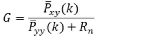
状態量の予測値を実際に観測された値でフィードバックする処理はカルマンゲイン(Kalman Gain)と呼ばれ、次式で計算される。なお、次式のRnは観測ノイズである。
次に、このカルマンゲインを用いて、状態量の事前予測値を補正する処理を次のように行う。

以上の事前推定部42及びフィルタリング部44の処理を各タイムステップごとに繰り返すことにより、姿勢角ua(k)を推定する。
The attitude angle u a (k) is estimated by repeating the processes of the
続いて位置推定部50における処理について説明する。図9は、本実施の形態に係る位置推定部50の機能ブロック図の一例である。図9に示したように、位置推定部50は、後述する状態変数の前回値xp(k-1)及び状態共分散の前回値Pnp
x(k-1)から横滑りモデルに基づいて予測値(事前推定値)を推定する事前推定部52と、事前推定部52が出力した事前推定値を、センサ入力ypと後述する観測共分散行列Rnpとを用いて補正して状態変数の次回値xp(k)、状態共分散の次回値Pnp
x(k)及び推定位置up(k)を出力するフィルタリング部54と、を含む。
Subsequently, the processing in the
なお、状態変数、状態共分散、観測共分散行列及び姿勢角の各々の添え字pは、Placeの略である。 The subscript p of each of the state variable, the state covariance, the observed covariance matrix, and the attitude angle is an abbreviation for Place.
位置推定部50では、車体座標系208における後輪車軸中心202の位置up=(Ev、Nv)を推定する事を目的とする。IMU26で検出したヨーレートRs、前後加速度Asx、横加速度Asy、車速センサで検出したUw、EN座標(Eloc、Nloc)に加え、操舵角δs及び姿勢角推定値ua=(φv、 θv、ψv)を入力して位置推定を行う。
The position estimation unit 50 aims to estimate the position up = (E v , N v ) of the rear
一般に車両200の横速度Vはとても小さいため、MEMSによって量産された誤差が大きなIMUのみでの推定は難しい。そこで本実施の形態では、操舵角δwと車速Uwとを入力値とした車両運動モデルを用いる事によって車両200の横速度Vvを推定する。
Since the lateral speed V of the
しかし、車両運動モデルの精度はタイヤパラメータに大きく依存するため、その精度が課題となっている。特に従来の車両200の重心を基準にした横速度V及びヨーレートRの推定手法では、車速Uwに応じて横滑りの方向が旋回内向きと外向きとで変化する。さらに車両200の重心は積載や人員等で変化する事が想定される。従って、車両200の重心に基づく推定では、横滑りの推定方向が逆になり、運動モデルによって位置推定を悪化させる場合が考えられる。
However, since the accuracy of the vehicle motion model greatly depends on the tire parameters, the accuracy is an issue. In particular, in the conventional method of estimating the lateral speed V and the yaw rate R based on the center of gravity of the
本実施の形態では、前述のように、後輪車軸中心202を車体座標系208の基準とし、車速によらず必ず旋回外方向に横速度Vが発生する車両運動モデルを想定した。
In the present embodiment, as described above, a vehicle motion model is assumed in which the rear
前述のように後輪操舵を行わない車両200については、後輪車軸中心202は車両運動の特性から必ず旋回の外側に横速度Vvを有する。従って注目すべきはモデルパラメータによる横滑りの大小関係のみになる。従って、前述のように、位置推定では上下速度Wv=0と仮定する。
As described above, for the
図3に示したように、横滑りを考慮しない場合はロボットの運動等でよく利用される非ホロノミック運動の事であり、真値に対して必ず旋回内側に位置が推定される。そこからCpを小さくしていき真値Cprealに近づけていくと、位置推定も真値に近づいていく。さらにCpを小さくしていくと真値から離れていく。以上から、Cpを実験等で求めた同定値に対して大きく設定しておくことで、必ず従来の非ホロノミック運動の位置と真の位置との間の推定が可能になる。かかる推定では、路面環境又はタイヤの履き替えによってタイヤパラメータが変化した場合の推定誤差見積もりも容易になる。 As shown in FIG. 3, when skidding is not taken into consideration, it is a nonholonomic motion that is often used in the motion of a robot, and the position is always estimated inside the turn with respect to the true value. If Cp is reduced from there and approaches the true value Cp real , the position estimation also approaches the true value. If Cp is further reduced, it will move away from the true value. From the above, by setting Cp larger than the identification value obtained by experiments or the like, it is possible to estimate between the position of the conventional nonholonomic motion and the true position without fail. In such an estimation, it is easy to estimate the estimation error when the tire parameters are changed due to the road surface environment or the change of tires.
以上を踏まえて、座標原点を後輪車軸中心202とした2輪モデルによる横速度Vの方程式を導出する。
Based on the above, the equation of the lateral speed V is derived by the two-wheel model with the coordinate origin as the rear
路面姿勢角のロール角をφr、ピッチ角をθrとすると、横方向の運動方程式は、次式によって表される。

上記の中のFyはy軸方向に働く力であり、下記の式に示したように、前輪タイヤ横力Ffと後輪タイヤ横力Frとの和で表される。
![]()
![]()
そして、前輪タイヤ横力Ff及び後輪タイヤ横力Frは次式で表される。

上記式に関連して、図10に示した車両200の重心CG周りの速度をvc=(Uc、Vc、Wc)、ヨーレートをRc、前輪実舵角をδw、重心CGから前輪車軸中心210までの距離をlf、重心CGから後輪車軸中心202までの距離をlr、前輪、後輪のコーナリングスティフネスを各々Kf、Kr、車両質量をmとした。
In relation to the above equation, the speed around the center of gravity CG of the
上記運動方程式のFyに前輪タイヤ横力Ff及び後輪タイヤ横力Frを代入して整理する。

その結果、横速度の運動方程式は下記のようになる。

上記式の最後の重力加速度gに関する項は、路面姿勢角による重力の影響を表す項であり、横速度推定を行う上で重要な項である。この項を省略してしまうと特にバンクが大きいような走路で位置推定精度が大きく劣化する。上記方程式を後輪車軸中心に変数変換をする上で3つの位置ベクトルを考える。地球座標系の原点から後輪車軸中心へのベクトルrew、地球座標系の原点から車両重心CGへのベクトルrec、車両重心CGから後輪車軸中心へのベクトルrcwを考えると、次式のような関係が成立する。
![]()
![]()
上記式を時間微分すると、重心における回転角速度ωcと後軸中心での回転角速度ωvは同じであることから、dr/dt=δr/δt + ω × rの関係を用いて下記のように整理される。

図10に示したように、車両200の後輪車軸中心202の前後速度をUv、横速度をVvとすると、以上の式より、Uv=Uc及びVv=Vc -lrRvとなる。これを横方向の運動方程式に用いると次式が誘導される。

上記の航法の方程式を用いて、以下、状態方程式fp(xp)を立式する。 Using the above navigation equation, the equation of state f p (x p ) is formulated below.
本実施の形態では、状態変数xpを下記のように定義する。
![]()
![]()
そして、姿勢角推定部40から入力される姿勢角入力値uaを下記のように定義する。
![]()
![]()
上記の状態量に対して、以下のように状態方程式を立式する。

また、本実施の形態では、状態量のシステムノイズを下記のように定義する。
![]()
![]()
前後速度Uvの微分値、横速度Vvの微分値及び操舵角δwは、次回値がランダムに出現するような白色ノイズによって駆動されるランダムウォークモデルとする。前後速度Uvの微分値、横速度Vvの微分値及び操舵角δwに1次のマルコフモデルを採用してもよい。 The differential value of the front-rear speed U v , the differential value of the lateral speed V v , and the steering angle δ w are random walk models driven by white noise such that the next value appears randomly. A first-order Markov model may be adopted for the differential value of the front-rear speed U v , the differential value of the lateral speed V v , and the steering angle δ w .
本実施の形態は、実舵角も推定対象としている点が特徴で、実舵角は必ずしも操舵角δwに対して一定比率で求まらず、コンプライアンス等で誤差が必ず生じている。この誤差は白色ノイズになっているとは限らないが、ある分散をもった値になっていると仮定する事で、2輪モデルによるモデル化誤差を状態方程式の分散としてカルマンフィルタの中に取り入れて扱う事が可能となる。 The feature of this embodiment is that the actual steering angle is also an estimation target, and the actual steering angle is not always obtained at a constant ratio with respect to the steering angle δ w , and an error always occurs in compliance or the like. This error is not always white noise, but by assuming that it has a certain variance, the modeling error by the two-wheel model is incorporated into the Kalman filter as the variance of the equation of state. It becomes possible to handle.
次に観測行列を下記のように定義する。

上記観測変数に対して、観測方程式hp(xp)を下記のように定義する。

上記式中のεswは実舵角と操舵角との比であり、ここでは定常値を仮定しているが、マップ化したものを適用する事も可能である。また、dVv/dtについては状態方程式と同様の式を利用するので省略した。この値は比較的小さく、加速度センサのノイズや誤差に隠れてしまうため、観測方程式から除いても位置推定精度に対する影響が小さい。 Ε sw in the above equation is the ratio of the actual steering angle to the steering angle, and although a steady value is assumed here, it is also possible to apply a mapped one. Also, dV v / dt is omitted because it uses the same equation as the equation of state. Since this value is relatively small and is hidden by the noise and error of the accelerometer, the influence on the position estimation accuracy is small even if it is excluded from the observation equation.
観測方程式の誤差共分散行列を下記のように定義する。
![]()
![]()
外界センサが使用できない慣性航法中はEN座標が取得できなくなるので、観測変数を次のように切り替える。
![]()
![]()
観測方程式についてはEN座標に係るEloc及びNlocを各々示す式を除いたものを用いればよい。状態変数の値と共分散行列について特に初期化等をする必要はなく、観測方程式の切り替えで正常時と慣性航法とを組み合わせればよい。 As the observation equation, the equations excluding the equations showing E loc and N loc related to EN coordinates may be used. It is not necessary to initialize the value of the state variable and the covariance matrix in particular, and it is sufficient to combine normal navigation and inertial navigation by switching the observation equations.
前述のように、位置推定部50は、状態変数の前回値xp(k-1)及び状態共分散の前回値Pnp
x(k-1)から横滑りモデルに基づいて予測値(事前推定値)を推定する事前推定部52と、事前推定部52が出力した事前推定値を、センサ入力ypと後述する観測共分散行列Rnpとを用いて補正して状態変数の次回値xp(k)、状態共分散の次回値Pnp
x(k)及び推定位置up(k)を出力するフィルタリング部54と、を含む。
As described above, the
位置推定部50の事前推定部52は、姿勢角推定部40の事前推定部42と同様に、図7に示したような第1アンセンティッド変換部と第2アンセンティッド変換部とを含む。
The
位置推定部50の第1アンセンティッド変換部は、状態方程式fp(xp)に基づいて状態量を更新する1回目のアンセンティッド変換を行って、xpの平均及びxpの共分散行列を出力する。
The first unscented conversion unit of the
位置推定部50の第2アンセンティッド変換部は、第1アンセンティッド変換部が出力した状態量xpの平均及び状態量xpの共分散行列を用いて、観測方程式hp(x)pに従って、対応する観測量に変換する2回目のアンセンティッド変換を行う。
The second uncentied conversion unit of the
そして、位置推定部50のフィルタリング部は、姿勢角推定部40のフィルタリング部44と同様に、状態量の事前予測値に対応する観測値と、実際に観測された観測値との差を比較し、状態量の予測値を補正する処理を行う。
Then, the filtering unit of the
以下、姿勢角推定部40と同様に、事前推定部52及びフィルタリング部54の処理を各タイムステップごとに繰り返すことにより、車両200の前後速度Uv、横速度Vv及びヨーレートRvの各々を推定する。そして、当該推定の直前の車両200の位置(EN座標)を車両200の位置の初期値とし、当該初期値と、姿勢角推定部40で推定した車両200の姿勢角(ピッチ角θv、ロール角φv及びヨー角ψv)と、推定した前後速度Uv、横速度Vv及びヨーレートRvとに基づいて、車両200の現在位置を推定する。
Hereinafter, similarly to the attitude
以上説明したように、本実施の形態に係る慣性航法装置10によれば、IMU26及び車速センサ24の各々の出力結果を用いて、車両200の姿勢角(ピッチ角θv、ロール角φv、ヨー角ψv)を推定すると共に、推定した姿勢角と、IMU26、車速センサ24及び操舵角センサ28の各々の出力結果とを用いて、車両200の位置を推定する。IMU26、車速センサ24及び操舵角センサ28は、車両200自身の状態を検知する内界センサである。
As described above, according to the
従って、本実施の形態に係る慣性航法装置10によれば、外界状況を検知するGPS等の外界センサからの情報が途絶した場合に、内界センサで検出した自車両の移動量の蓄積に基づいて自車両の位置を推定することができる。
Therefore, according to the
また、前述のように本実施の形態に係る慣性航法装置10は、路面を走行している車両200は上下速度Wv及び横速度Vvが小さいという特徴を利用して、姿勢角推定では4自由度(上下速度Wv=横速度Vv=0)と仮定し、位置推定では5自由度(上下速度Wv=0)と仮定して、次元を縮退することにより、慣性センサであるIMU26が高精度でなくても、又はIMU26の精度が劣化しても、車両200の姿勢角と車両200の位置とを安定して推定することができる。
Further, as described above, the
また、本実施の形態に係る慣性航法装置10では、横滑りが必ず旋回外方向になる点を横滑りモデルの基準点にしたことにより、車両重心位置CGを基準とした車両運動モデルのように、旋回方向が同じでも横滑りの方向が車速によって変化する現象は生じ得ない。その結果、本実施の形態に係る慣性航法装置10では、車両200の横滑りの大きさを高精度で推定することに伴い、車両200の位置を車速によらず高精度で推定することができる。
Further, in the
また、本実施の形態に係る慣性航法装置10は、非線形モデルであるアンセンティッドカルマンフィルタを用いて車両200の挙動を推定するので、路面傾斜のような非線形運動についても考慮することが可能となり、その結果、路面傾斜を考慮した車両200の横滑りの挙動を高精度で推定することができる。
Further, since the
10 慣性航法装置
12 入力装置
14 演算装置
16 表示装置
18 記憶装置
20 位置計測装置
24 車速センサ
28 操舵角センサ
40 姿勢角推定部
42 事前推定部
44 フィルタリング部
50 位置推定部
52 事前推定部
54 フィルタリング部
200 車両
202 後輪車軸中心
210 前輪車軸中心
10
Claims (7)
前記車両の前後速度を検出する車速検出部と、
前記車両の操舵角を検出する操舵角検出部と、
前記車両の上下速度及び横速度を0とみなし、前記慣性計測装置が検出した前記角速度と、前記慣性計測装置が検出した前記加速度と、前記車速検出部が検出した前後速度と、前記車両の方位角の初期値とに基づいて前記車両の姿勢角であるロール角、ピッチ角及び方位角を推定する姿勢角推定部と、
前記車両の上下速度を0とみなし、前記姿勢角推定部が推定した姿勢角と、前記慣性計測装置が検出した前記角速度と、前記慣性計測装置が検出した前記加速度と、前記車速検出部が検出した前後速度と、前記操舵角検出部が検出した操舵角と、前記車両の位置の初期値とに基づいて前記車両の現在位置を推定する位置推定部と、
を含む慣性航法装置。 An inertial measurement unit that can detect the angular velocity and acceleration that indicate the behavior of the vehicle while driving,
A vehicle speed detection unit that detects the front-rear speed of the vehicle, and
A steering angle detection unit that detects the steering angle of the vehicle, and
The vertical speed and lateral speed of the vehicle are regarded as 0, the angular velocity detected by the inertial measurement unit, the acceleration detected by the inertial measurement unit, the front-rear speed detected by the vehicle speed detection unit, and the azimuth of the vehicle. An attitude angle estimation unit that estimates the roll angle, pitch angle, and azimuth, which are the attitude angles of the vehicle, based on the initial values of the angles.
The vertical speed of the vehicle is regarded as 0, and the posture angle estimated by the posture angle estimation unit, the angular velocity detected by the inertial measurement unit, the acceleration detected by the inertial measurement unit, and the vehicle speed detection unit detect them. A position estimation unit that estimates the current position of the vehicle based on the front-rear speed, the steering angle detected by the steering angle detection unit, and the initial value of the vehicle position.
Inertial navigation system including.
前記姿勢角推定部は、前記慣性計測装置が検出したピッチレート、ロールレート及びヨーレートの3軸の角速度と、前記慣性計測装置が検出した前後加速度及び横加速度の2軸の加速度とを用いて前記車両の姿勢角を推定し、
前記位置推定部は、前記慣性計測装置が検出した1軸の角速度であるヨーレートと、前記慣性計測装置が検出した2軸の加速度である前後加速度及び横加速度と、姿勢角とを用いて前記車両の現在位置を推定する請求項1に記載の慣性航法装置。 The inertial measurement unit can detect the angular velocities of the three axes of pitch rate, roll rate and yaw rate, and the accelerations of the three axes of longitudinal acceleration, lateral acceleration and vertical acceleration.
The attitude angle estimation unit uses the three-axis angular velocities of pitch rate, roll rate, and yaw rate detected by the inertial measurement unit, and the two-axis accelerations of longitudinal acceleration and lateral acceleration detected by the inertial measurement unit. Estimate the attitude angle of the vehicle and
The position estimation unit uses the yaw rate, which is the angular velocity of one axis detected by the inertial measurement unit, the front-back acceleration and the lateral acceleration, which are the accelerations of the two axes detected by the inertial measurement unit, and the attitude angle. The inertial navigation system according to claim 1, wherein the current position of the is estimated.
前記慣性計測装置が検出した前記加速度と前記車両の運動との関係を表す式に基づいて、前回推定された、前記車両の姿勢角を含む前記車両の状態量から、次時刻の前記車両の状態量を予測する姿勢角推定用予測部と、
予め定められた観測方程式を用いて算出される、前記予測された次時刻の前記車両の状態量に対応する、車両前後速度、前記車両の角速度、及び前記車両の加速度と、それぞれの実測値との差分、及び前回推定された前記車両の状態量に基づいて、前記姿勢角推定用予測部で予測された前記車両の状態量を補正する姿勢角推定用更新部と、
を含み、
前記位置推定部は、
基準位置とした、前記車両の旋回時の前後速度によらず前記車両の横速度が旋回外方向に生じる基準位置を含む、前記加速度と前記車両の運動との関係を表す式と、前記姿勢角推定部で推定された姿勢角とに基づいて、前回推定された、前記車両の位置及び速度、加速度、角速度を含む前記車両の状態量から、次時刻の前記車両の状態量を予測する位置推定用予測部と、
予め定められた観測方程式を用いて算出される、前記予測された次時刻の前記車両の状態量に対応する、車両前後速度、前記車両の角速度、及び前記車両の加速度、前記車両の位置と、それぞれの実測値との差分、及び前回推定された前記車両の状態量に基づいて、前記位置推定用予測部で予測された前記車両の状態量を補正する位置推定用更新部と、
を含む請求項3~5のいずれか1項に記載の慣性航法装置。 The posture angle estimation unit is
Based on the equation expressing the relationship between the acceleration detected by the inertial measurement unit and the motion of the vehicle, the state of the vehicle at the next time is calculated from the state quantity of the vehicle including the posture angle of the vehicle previously estimated. A prediction unit for estimating the attitude angle that predicts the amount,
The vehicle front-rear speed, the angular velocity of the vehicle, and the acceleration of the vehicle corresponding to the state quantity of the vehicle at the predicted next time, which are calculated using a predetermined observation equation, and their measured values. The attitude angle estimation update unit that corrects the state amount of the vehicle predicted by the attitude angle estimation prediction unit based on the difference between the above and the previously estimated state amount of the vehicle.
Including
The position estimation unit is
An equation representing the relationship between the acceleration and the motion of the vehicle, including a reference position where the lateral speed of the vehicle occurs in the outward direction of the vehicle regardless of the front-rear speed of the vehicle when turning, and the posture angle as the reference position. Based on the attitude angle estimated by the estimation unit, the position estimation that predicts the state amount of the vehicle at the next time from the state amount of the vehicle including the position and speed, acceleration, and angular velocity of the vehicle previously estimated. Forecasting unit and
The vehicle front-rear speed, the angular velocity of the vehicle, the acceleration of the vehicle, and the position of the vehicle, which correspond to the state quantity of the vehicle at the predicted next time, calculated using a predetermined observation equation. A position estimation update unit that corrects the state amount of the vehicle predicted by the position estimation prediction unit based on the difference from each measured value and the previously estimated state amount of the vehicle.
The inertial navigation system according to any one of claims 3 to 5.
Priority Applications (2)
| Application Number | Priority Date | Filing Date | Title |
|---|---|---|---|
| JP2019070877A JP7036080B2 (en) | 2019-04-02 | 2019-04-02 | Inertial navigation system |
| US16/731,211 US11441905B2 (en) | 2019-04-02 | 2019-12-31 | Inertial navigation device and inertial navigation method |
Applications Claiming Priority (1)
| Application Number | Priority Date | Filing Date | Title |
|---|---|---|---|
| JP2019070877A JP7036080B2 (en) | 2019-04-02 | 2019-04-02 | Inertial navigation system |
Publications (2)
| Publication Number | Publication Date |
|---|---|
| JP2020169872A JP2020169872A (en) | 2020-10-15 |
| JP7036080B2 true JP7036080B2 (en) | 2022-03-15 |
Family
ID=72662942
Family Applications (1)
| Application Number | Title | Priority Date | Filing Date |
|---|---|---|---|
| JP2019070877A Active JP7036080B2 (en) | 2019-04-02 | 2019-04-02 | Inertial navigation system |
Country Status (2)
| Country | Link |
|---|---|
| US (1) | US11441905B2 (en) |
| JP (1) | JP7036080B2 (en) |
Families Citing this family (21)
| Publication number | Priority date | Publication date | Assignee | Title |
|---|---|---|---|---|
| US11187719B2 (en) * | 2019-01-08 | 2021-11-30 | Qualcomm Incorporated | In-motion initialization of accelerometer for accurate vehicle positioning |
| EP3954968A4 (en) * | 2019-04-09 | 2023-05-03 | Pioneer Corporation | POSITION ESTIMATING DEVICE, ESTIMATING DEVICE, CONTROL METHOD, PROGRAM AND INFORMATION MEDIA |
| DE102019003238B4 (en) * | 2019-05-08 | 2023-04-20 | Mercedes-Benz Group AG | Vehicle location by map comparison taking into account a street profile |
| JP7361348B2 (en) * | 2019-06-24 | 2023-10-16 | パナソニックIpマネジメント株式会社 | Video control device, video control method and program |
| KR20210057393A (en) * | 2019-11-12 | 2021-05-21 | 삼성전자주식회사 | Precise navigation apparatus and operating method thereof |
| US11175667B2 (en) * | 2020-02-19 | 2021-11-16 | GM Global Technology Operations LLC | System and method for vehicle integrated stability control using perceived yaw center |
| JP7770809B2 (en) * | 2020-11-04 | 2025-11-17 | キヤノン株式会社 | Information processing device, information processing method, and program |
| CN112660144B (en) * | 2020-12-04 | 2022-06-24 | 上汽通用五菱汽车股份有限公司 | Yaw rate filtering method, control terminal, vehicle and storage medium |
| CN113008244B (en) * | 2021-02-25 | 2023-07-14 | 广州导远电子科技有限公司 | Navigation information processing method, device, electronic device and storage medium |
| JP7642440B2 (en) * | 2021-05-19 | 2025-03-10 | 株式会社東芝 | Positioning device and positioning method |
| CN115597575B (en) * | 2021-07-09 | 2025-10-03 | 珠海一微半导体股份有限公司 | A robot side slip detection method, chip and robot |
| JP7729166B2 (en) * | 2021-10-15 | 2025-08-26 | 株式会社デンソー | Road surface condition estimation system, road surface condition estimation device, road surface condition estimation method, and road surface condition estimation program |
| US20230219561A1 (en) * | 2022-01-05 | 2023-07-13 | Motional Ad Llc | Vehicle state estimation augmenting sensor data for vehicle control and autonomous driving |
| US12228652B2 (en) * | 2022-08-29 | 2025-02-18 | Hyundai Mobis Co., Ltd. | Apparatus for estimating vehicle pose using lidar sensor and method thereof |
| JPWO2024048264A1 (en) * | 2022-08-29 | 2024-03-07 | ||
| CN116295458A (en) * | 2023-01-17 | 2023-06-23 | 惠州市德赛西威汽车电子股份有限公司 | A vehicle positioning method, system and vehicle-mounted terminal based on multi-data fusion |
| JP7766635B2 (en) * | 2023-03-22 | 2025-11-10 | 三菱電機株式会社 | Position estimation device, automatic driving system, position estimation method and program |
| CN116734845A (en) * | 2023-06-14 | 2023-09-12 | 北京集度科技有限公司 | A posture determination method, device, computer equipment and storage medium |
| CN116608851B (en) * | 2023-07-19 | 2023-09-26 | 中山大学 | Underground pipeline dual-robot step-by-step cooperative navigation method, system and server |
| US12351188B2 (en) * | 2023-11-28 | 2025-07-08 | GM Global Technology Operations LLC | Real-time reliability assessment method to enhance robustness of data-fusion based vehicle speed estimation |
| JP2025180770A (en) * | 2024-05-30 | 2025-12-11 | 株式会社ブリヂストン | Self-location estimation device, self-location estimation system, self-location estimation method, and self-location estimation program |
Citations (4)
| Publication number | Priority date | Publication date | Assignee | Title |
|---|---|---|---|---|
| JP2004239643A (en) | 2003-02-03 | 2004-08-26 | Furuno Electric Co Ltd | Hybrid navigator |
| JP2009236532A (en) | 2008-03-26 | 2009-10-15 | Seiko Epson Corp | Method for geolocation, program, and apparatus for geolocation |
| US20150088419A1 (en) | 2013-09-23 | 2015-03-26 | Texas Instruments Incorporated | Method, system and apparatus for vehicular navigation using inertial sensors |
| JP2018067034A (en) | 2016-10-17 | 2018-04-26 | パイオニア株式会社 | Mobile body control device, mobile body control method, and program for mobile body control device |
Family Cites Families (4)
| Publication number | Priority date | Publication date | Assignee | Title |
|---|---|---|---|---|
| JPH06317428A (en) | 1993-05-06 | 1994-11-15 | Tech Res & Dev Inst Of Japan Def Agency | Inertial navigation |
| US7885750B2 (en) * | 2006-08-30 | 2011-02-08 | Ford Global Technologies | Integrated control system for stability control of yaw, roll and lateral motion of a driving vehicle using an integrated sensing system to determine a sideslip angle |
| JP5419665B2 (en) | 2009-12-10 | 2014-02-19 | 三菱電機株式会社 | POSITION LOCATION DEVICE, POSITION LOCATION METHOD, POSITION LOCATION PROGRAM, Velocity Vector Calculation Device, Velocity Vector Calculation Method, and Velocity Vector Calculation Program |
| JP6693496B2 (en) | 2017-03-16 | 2020-05-13 | 株式会社デンソー | Self-location estimation device |
-
2019
- 2019-04-02 JP JP2019070877A patent/JP7036080B2/en active Active
- 2019-12-31 US US16/731,211 patent/US11441905B2/en active Active
Patent Citations (4)
| Publication number | Priority date | Publication date | Assignee | Title |
|---|---|---|---|---|
| JP2004239643A (en) | 2003-02-03 | 2004-08-26 | Furuno Electric Co Ltd | Hybrid navigator |
| JP2009236532A (en) | 2008-03-26 | 2009-10-15 | Seiko Epson Corp | Method for geolocation, program, and apparatus for geolocation |
| US20150088419A1 (en) | 2013-09-23 | 2015-03-26 | Texas Instruments Incorporated | Method, system and apparatus for vehicular navigation using inertial sensors |
| JP2018067034A (en) | 2016-10-17 | 2018-04-26 | パイオニア株式会社 | Mobile body control device, mobile body control method, and program for mobile body control device |
Also Published As
| Publication number | Publication date |
|---|---|
| US20200318971A1 (en) | 2020-10-08 |
| JP2020169872A (en) | 2020-10-15 |
| US11441905B2 (en) | 2022-09-13 |
Similar Documents
| Publication | Publication Date | Title |
|---|---|---|
| JP7036080B2 (en) | Inertial navigation system | |
| Ahmed et al. | Accurate attitude estimation of a moving land vehicle using low-cost MEMS IMU sensors | |
| CN106289275B (en) | Unit and method for improving positioning accuracy | |
| US9753144B1 (en) | Bias and misalignment compensation for 6-DOF IMU using GNSS/INS data | |
| Tin Leung et al. | A review of ground vehicle dynamic state estimations utilising GPS/INS | |
| US11167816B2 (en) | Control of a two-wheeled self-balancing vehicle | |
| CN113734180B (en) | Method and device for determining the speed of a vehicle | |
| EP2856273B1 (en) | Pose estimation | |
| Park | Optimal vehicle position estimation using adaptive unscented Kalman filter based on sensor fusion | |
| KR20190040818A (en) | 3D vehicular navigation system using vehicular internal sensor, camera, and GNSS terminal | |
| Xia et al. | Automated vehicle attitude and lateral velocity estimation using a 6-D IMU aided by vehicle dynamics | |
| JP6981459B2 (en) | Sensor error correction device | |
| JP7028223B2 (en) | Self-position estimator | |
| EP3429910B1 (en) | Control of a two-wheeled self-balancing vehicle | |
| JP7491339B2 (en) | Position estimation device, position estimation method, and position estimation program | |
| Liu et al. | Vehicle sideslip angle estimation: A review | |
| Alamdari et al. | Enhanced full-state estimation and dynamic-model-based prediction for road-vehicles | |
| JP2020097316A (en) | Vehicle attitude angle estimation device | |
| CN111284496B (en) | Lane tracking method and system for autonomous vehicles | |
| Hunter et al. | GNSS-Assisted System Identification of Autonomous Ground Vehicle Model and Sensor Parameters | |
| Baer et al. | EgoMaster: A central ego motion estimation for driver assist systems | |
| CN113030504B (en) | Vehicle speed measuring method and device, vehicle-mounted computer equipment and storage medium | |
| Wang et al. | Attitude estimation of multi-axis steering UGV using MEMS IMU | |
| JP2021142969A (en) | Sensor error correction device | |
| CN117804475B (en) | Vehicle-mounted fusion navigation method based on inertial satellite odometer and kinematic constraint |
Legal Events
| Date | Code | Title | Description |
|---|---|---|---|
| A621 | Written request for application examination |
Free format text: JAPANESE INTERMEDIATE CODE: A621 Effective date: 20200727 |
|
| A977 | Report on retrieval |
Free format text: JAPANESE INTERMEDIATE CODE: A971007 Effective date: 20210628 |
|
| A131 | Notification of reasons for refusal |
Free format text: JAPANESE INTERMEDIATE CODE: A131 Effective date: 20210706 |
|
| A521 | Request for written amendment filed |
Free format text: JAPANESE INTERMEDIATE CODE: A523 Effective date: 20210830 |
|
| TRDD | Decision of grant or rejection written | ||
| A01 | Written decision to grant a patent or to grant a registration (utility model) |
Free format text: JAPANESE INTERMEDIATE CODE: A01 Effective date: 20220201 |
|
| A61 | First payment of annual fees (during grant procedure) |
Free format text: JAPANESE INTERMEDIATE CODE: A61 Effective date: 20220214 |
|
| R150 | Certificate of patent or registration of utility model |
Ref document number: 7036080 Country of ref document: JP Free format text: JAPANESE INTERMEDIATE CODE: R150 |
|
| R250 | Receipt of annual fees |
Free format text: JAPANESE INTERMEDIATE CODE: R250 |