JP7019297B2 - Drainage pipe structure - Google Patents
Drainage pipe structure Download PDFInfo
- Publication number
- JP7019297B2 JP7019297B2 JP2017022462A JP2017022462A JP7019297B2 JP 7019297 B2 JP7019297 B2 JP 7019297B2 JP 2017022462 A JP2017022462 A JP 2017022462A JP 2017022462 A JP2017022462 A JP 2017022462A JP 7019297 B2 JP7019297 B2 JP 7019297B2
- Authority
- JP
- Japan
- Prior art keywords
- drainage
- connection port
- downstream
- pipe structure
- elbow
- Prior art date
- Legal status (The legal status is an assumption and is not a legal conclusion. Google has not performed a legal analysis and makes no representation as to the accuracy of the status listed.)
- Active
Links
Images


Landscapes
- Sink And Installation For Waste Water (AREA)
Description
本発明は、便器からの排水を排出する排水管構造に関する。 The present invention relates to a drainage pipe structure for draining drainage from a toilet bowl.
水洗式の便器には、様々な排水方式や洗浄水量を備えた製品がある。 Flush toilets include products with various drainage methods and flush water volumes.
例えば1970年代頃は、大便における洗浄水量を12~16Lとした便器が販売されており、時代とともに洗浄水量が減少し、2000年頃からは洗浄水量を6~8Lとした便器(以下、従来型便器という。)が販売されるようになった。 For example, around the 1970s, toilet bowls with a stool wash water volume of 12 to 16 L were sold, and the amount of wash water decreased with the times. From around 2000, toilet bowls with a wash water volume of 6 to 8 L (hereinafter referred to as conventional toilet bowls) ) Is now on sale.
現在では、洗浄水量を5L以下にした節水型便器の普及が進んでいる。 At present, water-saving toilets with a wash water volume of 5 L or less are becoming widespread.
また、洗浄水を貯めるロータンクを備えていない、いわゆるタンクレス式の節水型便器も、その清掃容易性やコンパクト性により人気を集めており、今後の普及が期待されている。 In addition, so-called tankless water-saving toilets that do not have a low tank for storing washing water are also gaining popularity due to their ease of cleaning and compactness, and are expected to become widespread in the future.
いずれの便器においても、便器の便鉢内に排泄された汚物は、トイレットペーパーとともに洗浄水によって下流側の排水管へ押し出されるように搬送されて、排出される。 In any of the toilet bowls, the filth excreted in the toilet bowl of the toilet bowl is transported together with the toilet paper by the washing water so as to be pushed out to the drain pipe on the downstream side and discharged.
そして、便器の排水方式や洗浄水量の違いによっては、排水管における汚物等の搬送性能に差が生じることがある。 Further, depending on the difference in the drainage method of the toilet bowl and the amount of washing water, the transport performance of filth and the like in the drainage pipe may be different.
洗浄水量が12L以上である便器が主流であった時代には、便器毎に搬送性能に差が生じたとしても、洗浄水量が多く排水管内で汚物等の詰まりが生じることは殆ど無かったが、洗浄水量の減少にともなって、汚物等の詰まりが懸念されるようになってきた。 In the era when toilet bowls with a wash water volume of 12 L or more were the mainstream, even if there was a difference in transport performance between toilet bowls, the amount of wash water was large and there was almost no clogging of filth in the drain pipe. With the decrease in the amount of washing water, there is a growing concern about clogging of filth and the like.
そこで、一般財団法人ベターリビングにより、2001年に「優良住宅部品性能試験方法書(便器)」が規定された。また、この優良住宅部品性能試験方法書(便器)では、「便器の搬送性能試験」が汚物等の搬送性能の評価基準として規定され、この搬送性能試験による基準(旧BL基準)を満たす便器が、一定水準以上の搬送性能の満たす便器として認知されている。 Therefore, in 2001, the General Incorporated Foundation Better Living stipulated the "Excellent Housing Parts Performance Test Method Manual (Toilet Bowl)". In addition, in this excellent housing parts performance test method manual (toilet bowl), "toilet bowl transport performance test" is stipulated as an evaluation standard for transport performance of filth, etc., and toilet bowls that meet the criteria (former BL standard) based on this transport performance test are , It is recognized as a toilet bowl that meets the transport performance above a certain level.
この旧BL基準は2011年に改正され、搬送メディアの負荷が軽減された新たな基準(新BL基準)に変更されている。 This old BL standard was revised in 2011 and changed to a new standard (new BL standard) that reduces the load on the transport media.
そして、現在では、搬送物の詰まりの報告が増加しており、その中でも、新BL基準に基づいた排水管構造を有する節水型便器で詰まりが発生することが多い。 At present, reports of clogging of transported materials are increasing, and among them, clogging often occurs in water-saving toilet bowls having a drainage pipe structure based on the new BL standard.
なお、現実の利用においては、汚物やトイレットペーパー等の搬送物の量は、トイレ使用者によって差があるため、完全に搬送物の詰まりを防止することは不可能であり、そもそも適正な搬送性能の基準をどのように決めるかは非常に難しい問題である。 In actual use, the amount of filth, toilet paper, and other items to be transported varies depending on the toilet user, so it is impossible to completely prevent clogging of the items to be transported. How to determine the standard of the toilet is a very difficult problem.
しかしながら、旧BL基準と新BL基準との詰まりの発生状況を比較すると、より負荷の大きい旧BL基準を満たす構成が好ましいのは明らかである。 However, when comparing the occurrence of clogging between the old BL standard and the new BL standard, it is clear that a configuration satisfying the old BL standard having a larger load is preferable.
現在では、新築住宅においては節水型便器が採用される場合が多いものの、排水管構造自体は従来のものが採用される。 At present, water-saving toilets are often used in new houses, but the drainage pipe structure itself is the conventional one.
また、リフォームを行なう際においても、便器は従来型便器から節水型便器に交換するものの、床下の排水管構造まで変更することは少ない。 In addition, even when remodeling, the toilet bowl is replaced with a water-saving toilet bowl from the conventional toilet bowl, but the drainage pipe structure under the floor is rarely changed.
ここで、例えば節水型便器等に接続する排水管構造において、搬送性能を向上させたものとしては、例えば特許文献1ないし特許文献3の構成が知られている。
Here, for example, in a drainage pipe structure connected to a water-saving toilet or the like, the configurations of Patent Document 1 to
特許文献1の排水管構造は、水位が低下した低水時における搬送性能を向上するために、例えば排水管の形状を卵形にすることで、低水時にも水深を確保する構成や、排水管の底部に凹凸を設けることで汚物等の搬送物の付着を防止する構成である。 The drainage pipe structure of Patent Document 1 has a structure for ensuring the water depth even at low water level by, for example, making the shape of the drainage pipe oval in order to improve the transport performance at low water level when the water level is low, and drainage. By providing unevenness on the bottom of the pipe, it is configured to prevent the adhesion of transported objects such as filth.
特許文献2の排水管構造は、便器直下の縦管部に整流面を有する突起(突条)を設けることで、排水に生じる乱流を抑える構成である。
The drainage pipe structure of
特許文献3の排水管構造は、便器直下の縦管部の内周面に凹部(凹所)または膨出部を設けることで、縦管部の中心を通過する搬送物や排水に対して、縦管部の内周面に沿って通過する排水が凹部または膨出部を伝うように流動し、排水がまとまって通過しないように排水流動時間を引き延ばす構成である。
The drainage pipe structure of
しかしながら、上述の特許文献1の構成では、同じ洗浄水量を流した場合に、通常の円形の排水管における水深よりも深くなるが、洗浄水量を5L以下まで低減した節水型便器では、排水管の形状を卵形にしただけでは、十分な水深を確保できず、十分な搬送性能を奏さない可能性がある。 However, in the configuration of Patent Document 1 described above, when the same amount of washing water is flowed, the water depth becomes deeper than that in a normal circular drainage pipe, but in a water-saving toilet bowl in which the amount of washing water is reduced to 5 L or less, the drainage pipe It is not possible to secure sufficient water depth just by making the shape oval, and there is a possibility that sufficient transport performance will not be achieved.
また、特許文献2の構成では、汚物等の搬送物が突起に直撃することで流動する排水に大きな乱流が生じる可能性や、汚物が突起に引っ掛かるように堆積して詰まりが生じる可能性が考えられる。
Further, in the configuration of
さらに、特許文献3の構成では、排水流動時間を引き延ばすだけであるため、搬送性能の根本的な改良とはならず、節水型便器等では十分な搬送性能を得ることができないと考えられる。
Further, in the configuration of
したがって、例えば節水型便器等に適用した場合であっても、旧BL基準を満たすように搬送性能が良好な排水管構造が求められていた。 Therefore, even when applied to, for example, a water-saving toilet, a drainage pipe structure having good transport performance has been required so as to satisfy the old BL standard.
本発明はこのような点に鑑みなされたもので、搬送性能を向上できる排水管構造を提供することを目的とする。 The present invention has been made in view of such a point, and an object of the present invention is to provide a drainage pipe structure capable of improving transport performance.
請求項1に記載された排水管構造は、排水を排出する排水管構造であって、前記排水管構造の管路途中に位置する断面視で略V字状の整流部を備え、前記整流部は、曲管部に設けられているものである。 The drainage pipe structure according to claim 1 is a drainage pipe structure for discharging drainage, and includes a substantially V-shaped rectifying portion in a cross-sectional view located in the middle of the pipeline of the drainage pipe structure, and the rectifying portion . Is provided in the curved pipe portion .
請求項2に記載された排水管構造は、便器からの排水を排出する排水管構造であって、前記便器に接続する縦管部と、この縦管部の下流側に接続する第1屈曲部と、この第1屈曲部の下流側に接続する第2屈曲部とを備え、少なくとも前記縦管部から前記第2屈曲部に至る管路の一部である曲管部には、断面視で略V字状の整流部が設けられているものである。
The drainage pipe structure according to
請求項3に記載された排水管構造は、便器からの排水を排出する排水管構造であって、前記便器に接続する縦管部と、この縦管部の下流側に接続し、前記縦管部の下流側の端部から屈曲する第1屈曲部と、この第1屈曲部の下流側に接続し、前記第1屈曲部の下流側の端部から略水平方向に屈曲する第2屈曲部とを備え、前記第1屈曲部は、曲管部の内周面に断面視で略V字状の整流部を有するものである。
The drainage pipe structure according to
請求項4に記載された排水管構造は、請求項2または3記載の排水管構造において、第1屈曲部は、屈曲における曲率半径が100mm以上140mm以下であるものである。
The drainage pipe structure according to claim 4 is the drainage pipe structure according to
請求項5に記載された排水管構造は、請求項2ないし4のいずれか一記載の排水管構造において、第1屈曲部と第2屈曲部とは、前記第1屈曲部の下流側軸心と前記第2屈曲部の上流側軸心とが一致する長さが120mm以下であるものである。
The drainage pipe structure according to
請求項6に記載された排水管構造は、請求項1ないし5のいずれか一記載の排水管構造において、整流部は、曲管部の底側に設けられているものである。The drainage pipe structure according to claim 6 is the drainage pipe structure according to any one of claims 1 to 5, wherein the rectifying portion is provided on the bottom side of the curved pipe portion.
本発明によれば、搬送性能を向上できる。 According to the present invention , the transport performance can be improved.
以下、本発明の一実施の形態の構成について図面を参照しながら詳細に説明する。 Hereinafter, the configuration of one embodiment of the present invention will be described in detail with reference to the drawings.
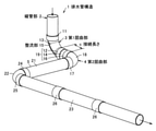
図1において、1は排水管構造で、この排水管構造1は、例えば節水型便器等の図示しない水洗式の便器に接続し、便器からの洗浄水等の排水とともに、汚物等の搬送物を搬送して排出する。 In FIG. 1, reference numeral 1 denotes a drainage pipe structure, and the drainage pipe structure 1 is connected to a flush toilet (not shown) such as a water-saving toilet, and drains water such as wash water from the toilet and transports filth and the like. Transport and discharge.
排水管構造1は、便器に接続する呼び径75mmの縦管部2と、この縦管部2の下流側に接続する呼び径75mmの第1屈曲部としての第1エルボ3と、この第1エルボ3の下流側に接続する第2屈曲部としての第2エルボ4と、この第2エルボ4の下流側に接続する水平管部5とを備えている。
The drain pipe structure 1 includes a
なお、呼び径とは、JIS規格における配管の外径寸法を示す。 The nominal diameter indicates the outer diameter dimension of the pipe in the JIS standard.
そして、便器からの汚物等の搬送物は、縦管部2から第1エルボ3および第2エルボ4を介して水平管部5を通過する排水の流動によって搬送されて、屋外の排水主管へ排出される。
Then, the transported material such as filth from the toilet bowl is transported from the
ここで、一般的に便器からの排水の流動による搬送物の搬送には、次のような現象が生じている。 Here, in general, the following phenomenon occurs in the transportation of the conveyed material by the flow of the drainage from the toilet bowl.
便器からの排水および搬送物に対して、便器からの排出の勢いと、縦管部2の落差による位置エネルギーとが排出初期の搬送エネルギーとなる。
With respect to the drainage from the toilet bowl and the transported material, the momentum of the discharge from the toilet bowl and the potential energy due to the head of the
そして、この搬送初期の搬送エネルギーは、搬送物や排水の配管内での摩擦等により徐々に低下する。 Then, the transport energy at the initial stage of transport gradually decreases due to friction in the pipes of the transported object and drainage.
しかし、略水平な水平管部5は、実際には空気調和・衛生工学会規格(SHASE-S206)における排水横管の所定の勾配(例えば配管勾配1/100)で設置しているため、その勾配による位置エネルギーが最終的な搬送エネルギーとなって搬送が続く。
However, since the substantially horizontal
この水平管部5での搬送の際には、流動する排水の先端および後端では、搬送時間の経過とともに重力により広がっていくため、次第に排水の水深が浅くなる。
During transportation in the
従来型便器のように例えば12L以上の十分な洗浄水量であれば、この水深が浅くなりすぎる前に搬送物が屋外の排水主管に到達するため、配管途中で詰まり等が発生しない。しかしながら、節水型便器のように従来型便器に比べて洗浄水量が少ない場合には、排水主管に達する前に排水の水深が浅くなりすぎて、搬送物が搬送されず、詰まりの発生を引き起こすことがある。 If the amount of washing water is sufficient, for example, 12 L or more as in a conventional toilet bowl, the conveyed material reaches the outdoor drainage main pipe before the water depth becomes too shallow, so that clogging or the like does not occur in the middle of the pipe. However, when the amount of washing water is smaller than that of a conventional toilet such as a water-saving toilet, the depth of the drainage becomes too shallow before reaching the drainage main pipe, and the transported material is not transported, causing clogging. There is.
本発明では、節水型便器からの搬送物の搬送に関しても、詰まりが発生せずに確実に搬送するために、搬送中の搬送物、例えばトイレットペーパーの搬送状態が重要である点に着目している。 In the present invention, it is focused on the point that the transport state of the transported material, for example, toilet paper, is important in order to reliably transport the transported material from the water-saving toilet without causing clogging. There is.
節水型便器のように洗浄水量が少ない便器では、従来型便器と異なりトイレットペーパーが排水に浮かぶようにして搬送されない。 In a toilet bowl with a small amount of washing water, such as a water-saving toilet bowl, the toilet paper is not transported as if it floats in the drainage, unlike the conventional toilet bowl.
つまり、搬送物であるトイレットペーパーは、便器の洗浄水量が少ないため、十分に排水に浮かばずに水平管部5の管底部(下部周縁)に接触しながら搬送される。
That is, since the amount of washing water in the toilet bowl is small, the toilet paper to be transported is transported while contacting the bottom portion (lower peripheral edge) of the
そして、水平管部5内でトイレットペーパーが堰のような状態となった場合には、排水がトイレットペーパーより下流側に越流しにくくなるため、トイレットペーパーの上流側の排水(以下、後方水という。)の水深の低下を遅らせることができる。そのため、節水型便器のように洗浄水量が少ない便器に適用しても、後方水による推進力を利用して搬送性能を向上できる。
When the toilet paper becomes like a dam in the
一方、水平管部5内でトイレットペーパーが堰のような状態になりきれなかった場合には、後方水が徐々にトイレットペーパーの下流側へ越流して、その分後方水の水深が低下するため、後方水による推進力が低下する。その結果、搬送性能が低下して、搬送物の搬送が水平管部5内で停止してしまう。
On the other hand, if the toilet paper cannot be completely formed like a weir in the
したがって、トイレットペーパー等の搬送物を配管内で幅方向に広がるようにコントロールして堰のような状態にして搬送できれば、搬送性能を向上できる。 Therefore, if it is possible to control the transported object such as toilet paper so as to spread in the width direction in the pipe and transport it in a state like a weir, the transport performance can be improved.
このような観点から、排水管構造1では、便器直下の縦管部2の下流側の端部から、第1エルボ3が略水平方向へ向けて略90度屈曲する。また、この第1エルボ3の下流側の端部から、第2エルボ4が略水平方向に略90度屈曲する。さらに、この第2エルボ4の下流側の端部から、水平管部5が略水平に延びている。
From this point of view, in the drainage pipe structure 1, the
なお、第1エルボ3、第2エルボ4および水平管部5の略水平方向とは、通常の排水管において必要な勾配を含み、例えば水平から2/100勾配までを含む。また、第1エルボ3および第2エルボ4の略90度とは、通常の排水管で使用されるいわゆる90度エルボ(JIS K 6739におけるDV継手、またはこの規格に準じる塩化ビニル管・継手協会規格(AS38:2010)におけるVU継手)の湾曲角度を含み、例えば90度から91度40分までを含む。
The substantially horizontal direction of the
縦管部2は、直管状の配管部材であり、便器直下に接続して略鉛直に配置する。
The
第1エルボ3は、縦管部2を水密に接続可能な上流側受口11と、この上流側受口11とは反対側の端部である下流側の端部に位置し直管状の配管部材である連結管14を水密に接続可能な下流側受口12と、これら上流側受口11と下流側受口12との間に位置し側面視で円弧状に屈曲した曲管部13とを有している。
The
この第1エルボ3は、上流側受口11の軸心である上流側軸心と、下流側受口12の軸心である下流側軸心とが略90度の位置関係になり、下流側受口12が水平方向へ向くように、曲管部13が屈曲している。
In this
また、図2および図3に示すように、第1エルボ3の曲管部13の内周面側は、断面視で略V字状の整流部15を有している。
Further, as shown in FIGS. 2 and 3, the inner peripheral surface side of the
整流部15は、曲管部13の底側(下側)のみに配置している。すなわち、曲管部13において整流部15が設けられた箇所では、円弧状の上面の下側に整流部15を一体に設けている。
The rectifying
整流部15は、断面視で略V字状、すなわち、断面視で真円よりも細い放物線状で、楕円的な弧状である。
The rectifying
整流部15は、通過する排水が突き当たる側に位置する円弧状の底面15aと、この底面15aの両側に位置する円弧状の側面15b,15cとを有している。
The rectifying
底面15aは、整流部15における円弧状の上面から円形状に延長した場合の想像上の円20a(図2において二点鎖線で示し、例えばφ83mmである。)に正接する円弧としており、側面15b,15cは、円20aの内側に位置している。
The
そして、円20aの外側で円20aの中心点から所定距離に位置する点を基準点20dとし、この基準点20dから底面15aと側面15bとの正接点に接する直線である基準線20bと、基準点20dから底面15aと側面15cとの正接点に接する直線である基準線20cとの角度を、整流部15のV字角度aとする。
Then, a point located outside the circle 20a at a predetermined distance from the center point of the circle 20a is set as a
なお、円20aの中心点から基準点20dまでの距離は、例えばV字角度aが90度、100度および110度の場合には、それぞれ50.2mm、48.0mmおよび46.2mmとする。また、円弧状の側面15bの中心点27aおよび円弧状の側面15cの中心点27bと、円20aの中心点および基準点20dを結ぶ直線に直交する直線との距離は、39.6mmとする。
The distances from the center point of the circle 20a to the
整流部15は、V字角度aが90度未満の場合、および、110度を超える場合には、適切な整流作用を奏さず、落下する排水に跳ね上げ等により乱流による位置エネルギー低下を十分に抑制できないため、搬送性能を十分に向上できない。したがって、整流部15のV字角度aは、90度以上110度以下とする。
When the V-shaped angle a is less than 90 degrees and when the V-shaped angle a exceeds 110 degrees, the rectifying
すなわち、整流部15は、円20aと底面15aとが正接し、かつ、基準点20dから底面15aと側面15bとの正接点を通る基準線20bと、基準点20dから底面15aと側面15cとの正接点を通る基準線20cとの角度であるV字角度aが90度以上110度以下となるように成形する。
That is, in the rectifying
第1エルボ3は、曲管部13の屈曲における曲率半径rが100mm未満の場合、および、140mmを超える場合には、搬送性能を向上できない可能性がある。したがって、第1エルボ3の曲管部13の曲率半径rは、100mm以上140mm以下が好ましい。
The
また、図3に示すように、曲管部13においては整流部15を一部の領域のみに設ける。すなわち、曲管部13における整流部15を設けた範囲は、上流側受口11側の端部および下流側受口12側の端部それぞれから15度の範囲である。
Further, as shown in FIG. 3, in the
第2エルボ4は、略90度屈曲した略円筒状の一般的なエルボ体である。 The second elbow 4 is a general elbow body having a substantially cylindrical shape bent by approximately 90 degrees.
このような第2エルボ4は、連結管14を水密に接続可能な上流側受口16と、この上流側受口16とは反対側の下流側の端部に位置し水平管部5を水密に接続可能な下流側受口17と、これら上流側受口16と下流側受口17との間に位置し側面視で円弧状に屈曲した曲管部18とを有している。
Such a second elbow 4 is located at an upstream receiving
第2エルボ4は、下流側受口17の軸心である下流側軸心が、上流側受口16の軸心である上流側軸心に対して略90度になり、下流側受口17が水平方向へ向くように曲管部18が屈曲している。
In the second elbow 4, the downstream side axis, which is the axis of the downstream
第1エルボ3と第2エルボ4とは、第1エルボ3の下流側受口12と第2エルボ4の上流側受口16とを連結管14を介して接続している。そして、これら第1エルボ3の下流側受口12と第2エルボ4の上流側受口16と連結管14とで接続部19を構成している。
The
接続部19では、第1エルボ3の下流側軸心と、第2エルボ4の上流側軸心とが一致している。この第1エルボ3の下流側軸心と第2エルボ4の上流側軸心とが一致する長さを第1エルボ3と第2エルボ4との接続長さcとし、連結管14の長さが接続長さcとなる。
At the
また、第1エルボ3と第2エルボ4との接続部19では、第1エルボ3の下流側軸心と第2エルボ4の上流側軸心とが一致する長さ(接続長さ)cが、120mmを超える場合に、搬送性能を向上できない可能性がある。したがって、第1エルボ3と第2エルボ4との接続長さcは、120mm以下が好ましい。
Further, in the
水平管部5は、第2エルボ4の下流側受口17に接続した直管状の配管部材である横管21と、この横管21に接続した第3屈曲部としての第3エルボ22と、この第3エルボ22に接続した横管23とを有している。
The
すなわち、水平管部5は、第2エルボ4の下流側受口17に横管21の一端部を接続し、横管21の他端部に第3屈曲部としての第3エルボ22の上流側受口24を接続する。また、第3エルボ22の下流側受口25に横管23を接続する。この横管23は、接続ソケット26を介して直管状の配管部材同士を接続する。
That is, the
次に、上記一実施の形態の作用および効果を説明する。 Next, the operation and effect of the above embodiment will be described.
上記排水管構造1によれば、縦管部2を通って落下するように流動する排水は、第1エルボ3において断面視で略V字状の整流部15に沿って流動することで、その整流作用によって排水の落下時の跳ね上がりを抑制し、流動する排水の散乱や乱流が発生することを抑制できる。そのため、縦管部2の落差に基づく位置エネルギーが損失されにくく、排水を円滑に行なって、位置エネルギーをより確実に搬送エネルギーとして搬送物に作用させることができる。
According to the drainage pipe structure 1, the drainage that flows so as to fall through the
また、第1エルボ3の下流側受口12に対して第2エルボ4が略水平方向へ略90度屈曲していることにより、搬送物が、第1エルボ3および第2エルボ4を通過するときに回転方向に力が加わることで幅方向に拡がりやすくなるため、流動する排水に対して堰のように作用しやすく、搬送中に搬送物の後方水の推進力をより確実に利用できる。そのため、整流部15により流動中の損失が抑制された排水の位置エネルギーを、搬送物への推進力として作用させやすい。
Further, since the second elbow 4 is bent approximately 90 degrees in the substantially horizontal direction with respect to the downstream receiving
したがって、排水管構造1によれは、タンクレス式の節水型便器のように洗浄水量が少なく、搬送性能に不利な条件である便器であっても、上述のように乱流の発生を抑止し位置エネルギーの低下を抑制するとともに、配管内で搬送物が幅方向に広がるため、搬送物の後方の後方水の推進力を十分に利用して、搬送性能を向上できる。また、便器からの排水に関する配管構造を構築する段階において、排水管構造1を設置しておけば、その時点で節水式便器を設置せず、将来的に節水式便器を設置することになった場合であっても、排水管構造1をそのまま利用でき、リフォーム等における将来的な変更工事が容易になる。 Therefore, according to the drainage pipe structure 1, the generation of turbulent flow is suppressed as described above even in a toilet bowl having a small amount of washing water and a disadvantageous condition for transport performance, such as a tankless water-saving toilet bowl. Since the decrease in potential energy is suppressed and the transported object spreads in the width direction in the pipe, the propulsive force of the rear water behind the transported object can be fully utilized to improve the transport performance. In addition, if the drainage pipe structure 1 is installed at the stage of constructing the piping structure for drainage from the toilet bowl, the water-saving toilet bowl will not be installed at that time, and the water-saving toilet bowl will be installed in the future. Even in this case, the drainage pipe structure 1 can be used as it is, and future change work such as remodeling becomes easy.
また、整流部15は、V字角度aが90度以上110度以下であることにより、整流部15による整流作用で排水の跳ね上げや散乱を抑制でき、搬送性能を向上できる。
Further, since the V-shaped angle a of the rectifying
第1エルボ3は、屈曲部分における曲率半径rが100mm以上140mm以下であることにより、縦管部2での位置エネルギーを利用して排水が円滑に流動でき、搬送性能を向上できる。
Since the radius of curvature r at the bent portion of the
第1エルボ3と第2エルボ4との接続部19における接続長さcが120mm以下であることにより、搬送エネルギーが高い状態のうちに第1エルボ3から第2エルボ4へ排水が流動することで効果的に回転方向に力が作用し、搬送性能を向上できる。
Since the connection length c at the
なお、上記一実施の形態のように、第1エルボ3の曲率半径rが100mm以上140mm以下である構成が好ましいが、このような構成には限定されず、第1エルボ3の曲率半径rは適宜決定できる。
It should be noted that, as in the above embodiment, the configuration in which the radius of curvature r of the
また、第1エルボ3と第2エルボ4との接続部19における接続長さcが120mm以下である構成が好ましいが、このような構成には限定されず、第1エルボ3と第2エルボ4との接続部の構成は適宜決定できる。
Further, a configuration in which the connection length c of the
以下、本発明に係る実施例および比較例について説明する。 Hereinafter, Examples and Comparative Examples according to the present invention will be described.
節水型便器への適用を考慮すると、新BL基準より旧BL基準で搬送性能を評価した方が詰まりの発生をより確実に防止できるため、旧BL基準に基づいて排水試験を行なって搬送性能を確認した。 Considering the application to water-saving toilets, it is better to evaluate the transport performance by the old BL standard than by the new BL standard, so that the occurrence of clogging can be prevented more reliably. confirmed.
まず、搬送メディアとして、JIS P 4501を満たすトイレットペーパー1mを6枚重ねて8つ折りにしたものを用いた。 First, as the transport medium, 6 sheets of 1 m of toilet paper satisfying JIS P 4501 were stacked and folded in eight.
なお、参考までに、新BL基準では、JIS P 4501を満たすトイレットペーパー90cmを8つ折りにして、4枚重ねたものを用いることになっている。 For reference, according to the new BL standard, toilet paper 90 cm satisfying JIS P 4501 is folded in eight and four sheets are stacked.
排水方法は、搬送メディアを内径が40mmの筒の中に丸めた状態で挿入し、この筒の先端を15秒間便鉢の水に完全に浸した後、筒を取り除いて直ちに大排水(大便用の排水)を行なった。 The drainage method is to insert the transport media into a cylinder with an inner diameter of 40 mm in a rolled state, completely immerse the tip of this cylinder in the water of the toilet bowl for 15 seconds, remove the cylinder, and immediately drain the large amount of water (for stool). Drainage) was performed.
配管内での搬送距離は、便器直下の継手から停止した状態の搬送メディアの最後尾までの距離とした。 The transport distance in the pipe was the distance from the joint directly under the toilet bowl to the end of the transport media in the stopped state.
ここで、旧BL基準では、5回の排水試験を行なった各搬送距離のうち、最大値および最小値を除外して3回の平均の搬送距離で評価し、この搬送距離が10m以上となった場合に搬送性能が満たされているものと判断している。 Here, according to the old BL standard, the average transport distance of 3 times is evaluated by excluding the maximum value and the minimum value from each transport distance of 5 times of drainage test, and this transport distance is 10 m or more. If so, it is judged that the transport performance is satisfied.
しかしながら、ばらつきの影響を極力抑え、できるだけ正確に搬送性能を評価するために、図1に示す排水管構造1(実施例)、および、図4に示す従来排水管構造31(比較例)について、各試験条件で排水試験を50回行ない、各試験結果(搬送距離)の最大値および最小値を除外せずに、各試験結果の中央値を搬送距離とし、その搬送距離が10m以上となった場合に、搬送性能を満たすと評価した。 However, in order to suppress the influence of variation as much as possible and evaluate the transport performance as accurately as possible, the drainage pipe structure 1 (Example) shown in FIG. 1 and the conventional drainage pipe structure 31 (comparative example) shown in FIG. 4 are used. The drainage test was performed 50 times under each test condition, and the median value of each test result was used as the transport distance without excluding the maximum and minimum values of each test result (transport distance), and the transport distance was 10 m or more. In some cases, it was evaluated as satisfying the transport performance.
実施例である排水管構造1では、便器直下で長さ300mmの縦管部2の下部に第1エルボ3の上流側受口11を接続し、その第1エルボ3の下流側受口12に連結管14の一端部を接続した。また、連結管14の他端部に第2エルボ4の上流側受口16を接続した。さらに、第2エルボ4の下流側受口17に、直管状で1mの横管21の一端部を接続した。また、横管21の他端部に第3屈曲部としての第3エルボ22の上流側受口24を接続し、第3エルボ22の下流側受口25に21mの横管23を接続ソケット26を介して接続した。
In the drainage pipe structure 1 of the embodiment, the upstream
なお、第2エルボ4および第3エルボ22は、塩化ビニル管・継手協会規格(AS38:2010)の90度大曲がりエルボを使用した。また、各配管の呼び径は75mmで、水平管部5の配管勾配は1/100である。
As the second elbow 4 and the
比較例である従来排水管構造31は、実施例に対して、第1エルボ3および第2エルボ4に代えてエルボ32を接続した。すなわち、エルボ32の上流側受口33に縦管部2を接続し、エルボ32の下流側受口34に横管21を接続した。なお、エルボ32には、塩化ビニル管・継手協会規格(AS38:2010)の90度大曲がりエルボを使用した。
In the conventional
[試験1]
節水型便器のタイプによる搬送性能の違いを確認するために、V字角度aを100度とし、曲率半径rを120mmとし、連結管14の長さ(接続長さc)を40mmとして、AないしCの便器において、排水試験を行なった。
[Test 1]
In order to confirm the difference in transport performance depending on the type of water-saving toilet, the V-shaped angle a is 100 degrees, the radius of curvature r is 120 mm, the length of the connecting pipe 14 (connection length c) is 40 mm, and A to A drainage test was performed on the toilet bowl of C.
なお、便器タイプAは、洗浄方式がトルネード洗浄(サイホン式)で、洗浄水量が3.8リットルである。便器タイプBは、洗浄方式がターントラップ式で、洗浄水量が4.8リットルである。便器タイプCは、洗浄方式がダイレクトバルブ式で、洗浄水量が5.0リットルである。 In the toilet type A, the cleaning method is tornado cleaning (siphon type), and the amount of cleaning water is 3.8 liters. The toilet type B has a turn trap type cleaning method and a cleaning water volume of 4.8 liters. The toilet bowl type C has a direct valve cleaning method and a cleaning water volume of 5.0 liters.
これら排水試験の結果を表1に示す。 The results of these drainage tests are shown in Table 1.

表1に示すように、排水管構造1を用いた実施例では、便器タイプAないしCのいずれも、搬送距離が10m以上であった。一方、従来排水管構造31を用いた比較例では、便器タイプAないしCのいずれも、搬送距離が10m未満であった。
As shown in Table 1, in the example using the drainage pipe structure 1, the transport distance was 10 m or more in each of the toilet bowl types A to C. On the other hand, in the comparative example using the conventional
他の条件で試験を行なうに際し、試験1の結果から、洗浄水量の観点では最も条件が厳しい便器タイプAにおいて十分な搬送性能が確認できれば、他のタイプの便器であっても搬送性能を十分に確保できると考え、試験2ないし試験6では、実施例である排水管構造1についてAの便器のみを用いて行なった。
When conducting a test under other conditions, if sufficient transport performance can be confirmed for the toilet type A, which has the strictest conditions in terms of the amount of washing water, from the results of test 1, the transport performance will be sufficient even for other types of toilets. Considering that it can be secured, in
[試験2]
最適なV字角度aを検討するため、曲率半径rを120mm、連結管14の長さ(接続長さc)を40mmとして、V字角度aの違いによる搬送距離の変化を確認した。
[Test 2]
In order to examine the optimum V-shaped angle a, the radius of curvature r was set to 120 mm, the length of the connecting pipe 14 (connection length c) was set to 40 mm, and the change in the transport distance due to the difference in the V-shaped angle a was confirmed.
試験を行なったV字角度aおよび搬送距離を表2に示す。 Table 2 shows the V-shaped angle a and the transport distance that were tested.

表2に示すように、V字角度aが90~110度の場合に、搬送距離が10m以上となり、特にV字角度aが100度の場合に最も良好な結果だった。 As shown in Table 2, when the V-shaped angle a is 90 to 110 degrees, the transport distance is 10 m or more, and the best result is particularly good when the V-shaped angle a is 100 degrees.
[試験3]
整流部15のV字角度aを100度とし、曲率半径rを120mmとし、連結管14の長さ(接続長さc)を40mmとした場合の第1エルボ3における整流作用を、撮影枚数が1000/sのハイスピードカメラでの撮影により分析した。
[Test 3]
When the V-shaped angle a of the rectifying
なお、比較のため、比較例である従来排水管構造31でも同様にハイスピードカメラで撮影した。
For comparison, the conventional
実施例および比較例いずれも、撮影により排水の流動状態が確認しやすいように各配管は透明なものを用いた。 In both the examples and the comparative examples, transparent pipes were used so that the flow state of the wastewater could be easily confirmed by photographing.
これら実施例および比較例について、便器からの排水開始1秒後の写真を図5に示す。図5(a)は実施例である排水管構造1の写真で、第1エルボ3における跳ね上がりを示す。また、図5(b)は比較例である従来排水管構造31の写真で、90度大曲がりエルボであるエルボ32における跳ね上がりを示す。なお、図5(a)および図5(b)のいずれも、右側の写真は左側の写真のA部を拡大したものである。
For these Examples and Comparative Examples, a photograph 1 second after the start of drainage from the toilet bowl is shown in FIG. FIG. 5A is a photograph of the drainage pipe structure 1 as an example, showing the jumping up in the
図中の小さな矢印は、各点における排水の流動ベクトルを示すが、図5(b)の従来排水管構造31では、流動ベクトルが配管内全体に散らばっており、跳ね上がりが多いことが確認できる。
The small arrows in the figure indicate the flow vector of the drainage at each point, but in the conventional
これに対して、図5(a)に示す排水管構造1では、流動ベクトルが配管内の下側半分に集まって跳ね上がりが少なく、かつ、その流動ベクトルの向きも概ね揃っていることが確認できる。 On the other hand, in the drainage pipe structure 1 shown in FIG. 5A, it can be confirmed that the flow vectors are gathered in the lower half of the pipe and the jump is small, and the directions of the flow vectors are almost the same. ..
したがって、排水管構造1は従来排水管構造31と比べて、排水の跳ね上がりや散乱が抑えられ、円滑に排水が行なわれており、整流作用が良好であることが確認できる。
Therefore, it can be confirmed that the drainage pipe structure 1 suppresses the splashing and scattering of the drainage as compared with the conventional
また、この排水試験での第3エルボ22から下流側7mの位置におけるトイレットペーパーの状態の写真を図6に示す。図6(a)が実施例である排水管構造1において第3エルボ22から下流側7mの位置を通過するトイレットペーパーの写真で、図6(b)が比較例である従来排水管構造31において第3エルボ22から下流側7mの位置を通過するトイレットペーパーの写真である。
Further, FIG. 6 shows a photograph of the state of the toilet paper at a position 7 m downstream from the
図6(b)の従来排水管構造31では、流動方向に対するトイレットペーパーの横方向の長さ、すなわち幅方向の長さが60mmであったのに対し、図6(a)の排水管構造1では、トイレットペーパーの幅方向の長さが70mmまで広がっていた。
In the conventional
したがって、排水管構造1は、従来排水管構造31に対して、配管内で流動中のトイレットペーパーが広がりやすく、後方水の越流を抑制できていることを確認できる。
Therefore, it can be confirmed that the drainage pipe structure 1 can easily spread the toilet paper flowing in the pipe and suppress the overflow of the rear water as compared with the conventional
[試験4]
第1エルボ3のV字角度aを100度とし、連結管14の長さ(接続長さc)を40mmとした場合において、第1エルボ3の曲率半径rの違いによる搬送距離の変化を確認した。各曲率半径rにおける搬送距離を表3に示す。
[Test 4]
When the V-shaped angle a of the

表3に示すように、曲率半径rが100~140mmの場合に搬送距離が良好であり、特に曲率半径rが120mmの場合に最も搬送距離が長くなった。 As shown in Table 3, the transport distance was good when the radius of curvature r was 100 to 140 mm, and the transport distance was the longest especially when the radius of curvature r was 120 mm.
[試験5]
第1エルボ3のV字角度aを100度とし、曲率半径rを120mmとした場合において、連結管14の長さ(接続長さc)の違いによる搬送距離の変化を確認した。各接続長さcにおける搬送距離を表4に示す。
[Test 5]
When the V-shaped angle a of the

表4に示すように、第1エルボ3と第2エルボ4との接続長さcが40mmから長くなるにしたがって搬送距離が短くなり、連結管14の長さが120mm以下の場合に搬送距離が良好であった。
As shown in Table 4, the transport distance becomes shorter as the connection length c between the
これら試験1ないし試験5の結果から、整流部15のV字角度aが100度で、第1エルボ3の曲率半径rが120mmで、連結管14の長さが40mmの場合に最も搬送距離が長くなることを確認できた。
From the results of Tests 1 to 5, the transport distance is the longest when the V-shaped angle a of the rectifying
[試験6]
上記試験1ないし試験5にて搬送距離が好ましかった条件の組み合わせについて、搬送距離を確認した。すなわち、整流部15のV字角度a(90~110度)、第1エルボ3の曲率半径r(100~140mm)、および、連結管14の長さ(40~120mm)の各条件の各組み合わせで排水試験を行なって搬送距離を確認した。
[Test 6]
In the above tests 1 to 5, the transport distance was confirmed for the combination of the conditions in which the transport distance was preferable. That is, each combination of the conditions of the V-shaped angle a (90 to 110 degrees) of the rectifying
まず、連結管14の長さが40mmの場合において、整流部15のV字角度aが90度、100度および110度のいずれかとし、第1エルボ3の曲率半径rが100mm、120mmおよび140mmのいずれかとして、排水試験を行なった結果を表5に示す。
First, when the length of the connecting

また、連結管14の長さが80mmの場合において、整流部15のV字角度aが90度、100度および110度のいずれかとし、第1エルボ3の曲率半径rが100mm、120mmおよび140mmのいずれかとして、排水試験を行なった結果を表6に示す。
When the length of the connecting

さらに、連結管14の長さが120mmの場合において、整流部15のV字角度aが90度、100度および110度のいずれかとし、第1エルボ3の曲率半径rが100mm、120mmおよび140mmのいずれかとして、排水試験を行なった結果を表7に示す。
Further, when the length of the connecting

これら表5ないし表7に示すように、整流部15のV字角度aが90度、100度および110度のいずれか、第1エルボ3の曲率半径rが100mm、120mmおよび140mmのいずれか、連結管14の長さが40mm、80mmおよび120mmのいずれかの場合であれば、どの条件の組み合わせでも搬送距離が良好であった。
As shown in Tables 5 to 7, the V-shaped angle a of the rectifying
1 排水管構造
2 縦管部
3 第1屈曲部としての第1エルボ
4 第2屈曲部としての第2エルボ
15 整流部
a V字角度
r 曲率半径
c 第1屈曲部の下流側軸線と第2屈曲部の上流側軸線とが一致する長さである接続長さ
1
15 rectifying part a V-shaped angle r radius of curvature c The connection length is the length at which the downstream axis of the first bending part and the upstream axis of the second bending part match.
Claims (6)
前記排水管構造の管路途中に位置する断面視で略V字状の整流部を備え、
前記整流部は、曲管部のうち上流側接続口側の端部および下流側接続口側の端部を除いた少なくとも一部の領域に設けられている
ことを特徴とする排水管構造。 It is a drainage pipe structure that discharges drainage.
It is provided with a substantially V-shaped rectifying section in a cross-sectional view located in the middle of the drainage pipe structure.
The drainage pipe structure is characterized in that the rectifying portion is provided in at least a part of the curved pipe portion excluding the end portion on the upstream side connection port side and the end portion on the downstream side connection port side .
前記便器に接続する縦管部と、
この縦管部の下流側に接続する第1屈曲部と、
この第1屈曲部の下流側に接続する第2屈曲部とを備え、
前記第1屈曲部は、
上流側の端部に位置する上流側接続口と、
下流側の端部に位置する下流側接続口と、
前記上流側接続口と前記下流側接続口との間に位置する曲管部とを有し、
少なくとも前記縦管部から前記第2屈曲部に至る管路の一部である前記曲管部のうち、前記上流側接続口側の端部および前記下流側接続口側の端部を除いた少なくとも一部の領域には、断面視で略V字状の整流部が設けられている
ことを特徴とする排水管構造。 It is a drainage pipe structure that drains drainage from the toilet bowl.
The vertical pipe part connected to the toilet bowl and
The first bent portion connected to the downstream side of this vertical pipe portion and
A second bent portion connected to the downstream side of the first bent portion is provided.
The first bent portion is
The upstream connection port located at the upstream end,
The downstream connection port located at the downstream end,
It has a curved pipe portion located between the upstream side connection port and the downstream side connection port.
At least the curved pipe portion that is a part of the pipeline from the vertical pipe portion to the second bent portion , excluding the end portion on the upstream side connection port side and the end portion on the downstream side connection port side. A drainage pipe structure characterized in that a substantially V-shaped rectifying section is provided in a part of the area in a cross-sectional view.
前記便器に接続する縦管部と、
この縦管部の下流側に接続し、前記縦管部の下流側の端部から屈曲する第1屈曲部と、
この第1屈曲部の下流側に接続し、前記第1屈曲部の下流側の端部から略水平方向に屈曲する第2屈曲部とを備え、
前記第1屈曲部は、
上流側の端部に位置する上流側接続口と、
下流側の端部に位置する下流側接続口と、
前記上流側接続口と前記下流側接続口との間に位置し、内周面に断面視で略V字状の整流部が設けられた曲管部とを有し、
前記整流部は、前記曲管部のうち前記上流側接続口側の端部および前記下流側接続口側の端部を除いた少なくとも一部の領域に設けられ、かつ、通過する排水が突き当たる側に位置する円弧状の底面と、この底面の両側に位置するとともに当該底面とは異なる円弧状の側面とを有する
ことを特徴とする排水管構造。 It is a drainage pipe structure that drains drainage from the toilet bowl.
The vertical pipe part connected to the toilet bowl and
A first bent portion that is connected to the downstream side of the vertical pipe portion and bends from the downstream end portion of the vertical pipe portion.
It is provided with a second bent portion that is connected to the downstream side of the first bent portion and bends in a substantially horizontal direction from the downstream end portion of the first bent portion.
The first bent portion is
The upstream connection port located at the upstream end,
The downstream connection port located at the downstream end,
It has a curved tube portion located between the upstream side connection port and the downstream side connection port and provided with a substantially V-shaped rectifying portion on the inner peripheral surface in a cross-sectional view.
The rectifying portion is provided in at least a part of the curved pipe portion excluding the end portion on the upstream side connection port side and the end portion on the downstream side connection port side, and the side on which the passing drainage abuts. It has an arc-shaped bottom surface located at, and an arc-shaped side surface located on both sides of this bottom surface and different from the bottom surface.
The drainage pipe structure is characterized by that.
整流部は、側面視で円弧状に屈曲している
ことを特徴とする請求項2または3記載の排水管構造。 In the first bent portion, the radius of curvature of the curved tube portion bent in an arc shape in a side view is 100 mm or more and 140 mm or less.
The straightening part is bent in an arc shape when viewed from the side.
The drainage pipe structure according to claim 2 or 3, wherein the drainage pipe structure is characterized.
前記第1屈曲部の上流側接続口および下流側接続口は、いずれも略円筒状に形成されている
ことを特徴とする請求項2ないし4のいずれか一記載の排水管構造。 The length of the first bent portion and the second bent portion is 120 mm or less so that the downstream axis of the first bent portion and the upstream axis of the second bent portion coincide with each other.
Both the upstream side connection port and the downstream side connection port of the first bent portion are formed in a substantially cylindrical shape.
The drainage pipe structure according to any one of claims 2 to 4, wherein the drainage pipe structure is characterized.
前記曲管部のうち上流側の領域は、略円筒状の上流側接続口側に向かって拡径状に形成され、
前記曲管部のうち下流側の領域は、略円筒状の下流側接続口側に向かって拡径状に形成されている
ことを特徴とする請求項1ないし5のいずれか一記載の排水管構造。 The rectifying section is provided on the bottom side of the curved tube section.
The region on the upstream side of the curved tube portion is formed in a substantially cylindrical shape toward the upstream side connection port side in an enlarged diameter.
The area on the downstream side of the curved tube portion is formed in a substantially cylindrical shape toward the downstream side connection port side in an enlarged diameter.
The drainage pipe structure according to any one of claims 1 to 5, wherein the drainage pipe structure is characterized.
Priority Applications (1)
| Application Number | Priority Date | Filing Date | Title |
|---|---|---|---|
| JP2017022462A JP7019297B2 (en) | 2017-02-09 | 2017-02-09 | Drainage pipe structure |
Applications Claiming Priority (1)
| Application Number | Priority Date | Filing Date | Title |
|---|---|---|---|
| JP2017022462A JP7019297B2 (en) | 2017-02-09 | 2017-02-09 | Drainage pipe structure |
Publications (3)
| Publication Number | Publication Date |
|---|---|
| JP2018127838A JP2018127838A (en) | 2018-08-16 |
| JP2018127838A5 JP2018127838A5 (en) | 2020-02-27 |
| JP7019297B2 true JP7019297B2 (en) | 2022-02-15 |
Family
ID=63172306
Family Applications (1)
| Application Number | Title | Priority Date | Filing Date |
|---|---|---|---|
| JP2017022462A Active JP7019297B2 (en) | 2017-02-09 | 2017-02-09 | Drainage pipe structure |
Country Status (1)
| Country | Link |
|---|---|
| JP (1) | JP7019297B2 (en) |
Families Citing this family (1)
| Publication number | Priority date | Publication date | Assignee | Title |
|---|---|---|---|---|
| JP7293450B2 (en) * | 2021-07-21 | 2023-06-19 | 積水化学工業株式会社 | Siphon drainage system |
Citations (1)
| Publication number | Priority date | Publication date | Assignee | Title |
|---|---|---|---|---|
| JP2013204363A (en) | 2012-03-29 | 2013-10-07 | Sekisui Chem Co Ltd | Drainage system |
Family Cites Families (2)
| Publication number | Priority date | Publication date | Assignee | Title |
|---|---|---|---|---|
| JP2848728B2 (en) * | 1991-12-03 | 1999-01-20 | 積水化学工業株式会社 | Drainage equipment |
| JPH09302743A (en) * | 1996-05-20 | 1997-11-25 | Noriatsu Kojima | Pipe structure for bent pipeline |
-
2017
- 2017-02-09 JP JP2017022462A patent/JP7019297B2/en active Active
Patent Citations (1)
| Publication number | Priority date | Publication date | Assignee | Title |
|---|---|---|---|---|
| JP2013204363A (en) | 2012-03-29 | 2013-10-07 | Sekisui Chem Co Ltd | Drainage system |
Also Published As
| Publication number | Publication date |
|---|---|
| JP2018127838A (en) | 2018-08-16 |
Similar Documents
| Publication | Publication Date | Title |
|---|---|---|
| JP6765627B2 (en) | Drainage socket | |
| JP6956944B2 (en) | Washing toilet bowl | |
| JP6204678B2 (en) | Piping unit, piping structure and drainage system | |
| JP2018112005A (en) | Water closet | |
| JP7019297B2 (en) | Drainage pipe structure | |
| CN108301479A (en) | Punching falls formula closet | |
| JP2003113990A (en) | Drain pipe channel and piping material used for drain pipe channel | |
| JP3459041B2 (en) | Drain pipe connection socket | |
| JP2018127838A5 (en) | ||
| JP7055274B2 (en) | Washing toilet | |
| JP7436178B2 (en) | drain pipe structure | |
| JP7421305B2 (en) | How to clean pipe fittings, pipes, and drain pipes | |
| JP2011058208A (en) | Flush toilet bowl | |
| JP6944745B2 (en) | Drain trap | |
| JP5967872B2 (en) | Drain pipe connection structure | |
| US10724223B2 (en) | Urinal | |
| JP6802516B2 (en) | Flush toilet | |
| JP3322963B2 (en) | Drainage pipe | |
| JP6808175B2 (en) | Sewage for ostomates | |
| JP2017053203A (en) | Toilet unit | |
| JP4274976B2 (en) | Inner / sub pipe joint | |
| JP4376234B2 (en) | Leg bend for drainage piping | |
| JP4617414B2 (en) | Overflow device | |
| JP6397260B2 (en) | Join | |
| JP6731292B2 (en) | Negative pressure suction toilet |
Legal Events
| Date | Code | Title | Description |
|---|---|---|---|
| A521 | Request for written amendment filed |
Free format text: JAPANESE INTERMEDIATE CODE: A523 Effective date: 20200114 |
|
| A621 | Written request for application examination |
Free format text: JAPANESE INTERMEDIATE CODE: A621 Effective date: 20200114 |
|
| A977 | Report on retrieval |
Free format text: JAPANESE INTERMEDIATE CODE: A971007 Effective date: 20201218 |
|
| A131 | Notification of reasons for refusal |
Free format text: JAPANESE INTERMEDIATE CODE: A131 Effective date: 20210106 |
|
| A521 | Request for written amendment filed |
Free format text: JAPANESE INTERMEDIATE CODE: A523 Effective date: 20210212 |
|
| A131 | Notification of reasons for refusal |
Free format text: JAPANESE INTERMEDIATE CODE: A131 Effective date: 20210714 |
|
| A521 | Request for written amendment filed |
Free format text: JAPANESE INTERMEDIATE CODE: A523 Effective date: 20210907 |
|
| TRDD | Decision of grant or rejection written | ||
| A01 | Written decision to grant a patent or to grant a registration (utility model) |
Free format text: JAPANESE INTERMEDIATE CODE: A01 Effective date: 20220119 |
|
| A61 | First payment of annual fees (during grant procedure) |
Free format text: JAPANESE INTERMEDIATE CODE: A61 Effective date: 20220202 |
|
| R150 | Certificate of patent or registration of utility model |
Ref document number: 7019297 Country of ref document: JP Free format text: JAPANESE INTERMEDIATE CODE: R150 |