[go: up one dir, main page]

JP6997479B1 - Water purification treatment system - Google Patents

Water purification treatment system Download PDF

Info

Publication number
JP6997479B1
JP6997479B1 JP2021078495A JP2021078495A JP6997479B1 JP 6997479 B1 JP6997479 B1 JP 6997479B1 JP 2021078495 A JP2021078495 A JP 2021078495A JP 2021078495 A JP2021078495 A JP 2021078495A JP 6997479 B1 JP6997479 B1 JP 6997479B1
Authority
JP
Japan
Prior art keywords
water
purification treatment
treated
air diffuser
compressed air
Prior art date
Legal status (The legal status is an assumption and is not a legal conclusion. Google has not performed a legal analysis and makes no representation as to the accuracy of the status listed.)
Active
Application number
JP2021078495A
Other languages
Japanese (ja)
Other versions
JP2022172580A (en
Inventor
克視 三富
琢也 井上
真隆 鈴木
恵介 渡辺
隆介 ▲高▼田
博義 石山
Current Assignee (The listed assignees may be inaccurate. Google has not performed a legal analysis and makes no representation or warranty as to the accuracy of the list.)
Shin Nippon Feather Core Co Ltd
Original Assignee
Shin Nippon Feather Core Co Ltd
Priority date (The priority date is an assumption and is not a legal conclusion. Google has not performed a legal analysis and makes no representation as to the accuracy of the date listed.)
Filing date
Publication date
Application filed by Shin Nippon Feather Core Co Ltd filed Critical Shin Nippon Feather Core Co Ltd
Priority to JP2021078495A priority Critical patent/JP6997479B1/en
Application granted granted Critical
Publication of JP6997479B1 publication Critical patent/JP6997479B1/en
Publication of JP2022172580A publication Critical patent/JP2022172580A/en
Active legal-status Critical Current
Anticipated expiration legal-status Critical

Links

Images

Classifications

    • YGENERAL TAGGING OF NEW TECHNOLOGICAL DEVELOPMENTS; GENERAL TAGGING OF CROSS-SECTIONAL TECHNOLOGIES SPANNING OVER SEVERAL SECTIONS OF THE IPC; TECHNICAL SUBJECTS COVERED BY FORMER USPC CROSS-REFERENCE ART COLLECTIONS [XRACs] AND DIGESTS
    • Y02TECHNOLOGIES OR APPLICATIONS FOR MITIGATION OR ADAPTATION AGAINST CLIMATE CHANGE
    • Y02WCLIMATE CHANGE MITIGATION TECHNOLOGIES RELATED TO WASTEWATER TREATMENT OR WASTE MANAGEMENT
    • Y02W10/00Technologies for wastewater treatment
    • Y02W10/10Biological treatment of water, waste water, or sewage

Landscapes

  • Biological Treatment Of Waste Water (AREA)
  • Separation Using Semi-Permeable Membranes (AREA)
  • Activated Sludge Processes (AREA)

Abstract

Figure 0006997479000001

【課題】新規な構造の水浄化処理システムを提供すること
【解決手段】
被処理水槽内に設置され、被処理水を浄化処理する浄化処理ユニットと、前記被処理水槽内に設置され、前記被処理水槽内に貯留される被処理水を曝気する散気装置と、を備える水浄化処理システムであって、前記散気装置は、圧縮空気供給装置と送気管で連通されているとともに、前記浄化処理ユニット及び前記散気装置を洗浄する洗浄液を供給する洗浄液タンクと洗浄液流路で連通され、前記被処理水のろ過処理時又は、前記浄化処理ユニット及び前記散気装置の洗浄時に、前記圧縮空気供給装置から前記散気装置への圧縮空気の供給と前記洗浄液流路への前記洗浄液の供給の切替を制御する制御手段を備えることを特徴とする水浄化処理システム。
【選択図】図1

Figure 0006997479000001

PROBLEM TO BE SOLVED: To provide a water purification treatment system having a new structure.
A purification treatment unit installed in the water tank to be treated to purify the water to be treated, and an air diffuser installed in the water tank to be treated to aerate the water to be treated stored in the water tank to be treated. A water purification treatment system including a cleaning liquid tank and a cleaning liquid flow that are communicated with a compressed air supply device by an air supply pipe and supply a cleaning liquid for cleaning the purification treatment unit and the air diffuser. It is communicated by a road to supply compressed air from the compressed air supply device to the air diffuser and to the cleaning liquid flow path during the filtration treatment of the water to be treated or the cleaning of the purification treatment unit and the air diffuser. A water purification treatment system comprising a control means for controlling switching of supply of the cleaning liquid.
[Selection diagram] Fig. 1

Description

この発明は、水浄化処理システムに関する。 The present invention relates to a water purification treatment system.

下水、排水等を浄化処理する方法の一つとして膜分離活性汚泥法(MBR: Membrane Bioreactor)が知られている。MBRでは、精密ろ過膜や限外ろ過膜といった分離膜で処理水と活性汚泥の分離が行われるが、分離膜の目詰まりを防止するため、定期的に分離膜を洗浄する必要がある。 The membrane separation activated sludge method (MBR: Membrane Bioreactor) is known as one of the methods for purifying sewage and wastewater. In MBR, treated water and activated sludge are separated by a separation membrane such as a microfiltration membrane or an ultrafiltration membrane, but it is necessary to clean the separation membrane regularly to prevent clogging of the separation membrane.

特許文献1には、次亜塩素酸ナトリウムを含んだ第1洗浄水を供給する洗浄フラックスよりもオゾンを含んだ第2洗浄水を供給する洗浄フラックスが高くなるように制御して排水の状況に応じた柔軟な逆洗が実現できる膜分離活性汚泥システムが提案されている。 In Patent Document 1, the cleaning flux for supplying the second cleaning water containing ozone is controlled to be higher than the cleaning flux for supplying the first cleaning water containing sodium hypochlorite, and the state of drainage is adjusted. A membrane separation active sludge system that can realize flexible backwashing according to the situation has been proposed.

特許文献2には、2種類以上の濃厚薬液をそれぞれ別の薬液タンクに貯留し、切り替え弁により2種類以上の洗浄液を通液して分離膜ユニットを洗浄する方法が提案されている。 Patent Document 2 proposes a method in which two or more kinds of concentrated chemicals are stored in different chemical tanks, and two or more kinds of cleaning solutions are passed through a switching valve to clean the separation membrane unit.

特許第6617860号公報Japanese Patent No. 6617860 特開2005-193132号公報Japanese Unexamined Patent Publication No. 2005-193132

上記で提案されているものの他、新規な構造の水浄化処理システムの提案が望まれている。 In addition to the ones proposed above, it is desired to propose a water purification treatment system with a new structure.

この発明は、新規な構造の水浄化処理システムを提供することを目的とする。 It is an object of the present invention to provide a water purification treatment system having a novel structure.

[1]
被処理水槽内に設置され、被処理水を浄化処理する浄化処理ユニットと、前記被処理水槽内に設置され、前記被処理水槽内に貯留される被処理水を曝気する散気装置と、を備える水浄化処理システムであって、
前記浄化処理ユニットは、前記浄化処理ユニット及び前記散気装置を洗浄する洗浄液を供給する洗浄液タンクと洗浄液流路で連通され、
前記散気装置は、圧縮空気供給装置と送気管で連通されているとともに、前記洗浄液タンクと洗浄液流路で連通され
記圧縮空気供給装置から前記散気装置への圧縮空気の供給と前記洗浄液タンクから前記浄化処理ユニット及び前記散気装置への前記洗浄液の供給の切替を制御する制御手段を備え
前記制御手段は、
前記浄化処理ユニットの洗浄時に、前記洗浄液タンクから前記浄化処理ユニットへの前記洗浄液の供給と、前記圧縮空気供給装置から前記散気装置への前記圧縮空気の供給とを同時に行う
ことを特徴とする水浄化処理システム。
[1]
A purification treatment unit installed in the water tank to be treated to purify the water to be treated, and an aeration device installed in the water tank to be treated to aerate the water to be treated stored in the water tank to be treated. It is a water purification treatment system that is equipped.
The purification treatment unit is communicated with a cleaning liquid tank for supplying a cleaning liquid for cleaning the purification treatment unit and the air diffuser by a cleaning liquid flow path.
The air diffuser is communicated with the compressed air supply device by an air supply pipe, and is also communicated with the cleaning liquid tank by a cleaning liquid flow path .
A control means for controlling switching between the supply of compressed air from the compressed air supply device to the air diffuser and the supply of the cleaning liquid from the cleaning liquid tank to the purification processing unit and the air diffuser is provided .
The control means is
At the time of cleaning the purification treatment unit, the cleaning liquid is supplied from the cleaning liquid tank to the purification treatment unit and the compressed air is supplied from the compressed air supply device to the air diffuser at the same time.
A water purification treatment system characterized by this.

この発明によれば、新規な構造の水浄化処理システムを提供することができる。 According to the present invention, it is possible to provide a water purification treatment system having a novel structure.

本実施形態の水浄化処理システムの構成の一例を表す図である。It is a figure which shows an example of the structure of the water purification treatment system of this embodiment. 汚泥の浄化処理の一例を表す図である。It is a figure which shows an example of the purification process of sludge. 浄化処理ユニットの洗浄処理の一例を表す図である。It is a figure which shows an example of the cleaning process of a purification process unit. 散気装置の洗浄処理の一例を表す図である。It is a figure which shows an example of the cleaning process of an air diffuser. 本実施形態の水浄化処理システムの構成の他の一例を表し、一部の要素を省略した図である。It shows another example of the structure of the water purification treatment system of this embodiment, and is the figure which omitted some elements. 図5図示の実施形態の水浄化処理システムにおけるスクリーンの一例を表す図である。FIG. 5 is a diagram showing an example of a screen in the water purification treatment system of the illustrated embodiment. 図1又は図5図示の実施形態の水浄化処理システムにおける浄化処理ユニットの一例を表す斜視図である。FIG. 1 or FIG. 5 is a perspective view showing an example of a purification treatment unit in the water purification treatment system of the illustrated embodiment. 本実施形態の水浄化処理システムの構成の他の一例を表し、一部の要素を省略した図である。It shows another example of the structure of the water purification treatment system of this embodiment, and is the figure which omitted some elements. 本実施形態の水浄化処理システムが備える散気装置の構成の一例を表す図であって、(a)斜視図、(b)図9(a)の破線で示した部分の拡大図である。It is a figure showing an example of the structure of the air diffuser provided in the water purification treatment system of this embodiment, and is the enlarged view of the part shown by the broken line of (a) perspective view, (b) FIG. 9 (a). (a)、(b)ともに図9に示す散気装置の動作を示す図である。Both (a) and (b) are diagrams showing the operation of the air diffuser shown in FIG.

以下、添付図面を参照して、本発明の実施形態の一例を説明する。 Hereinafter, an example of an embodiment of the present invention will be described with reference to the accompanying drawings.

(実施の形態1)
[水浄化処理システムの構成]
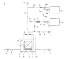
本実施形態の水浄化処理システム1は、一例として膜分離活性汚泥法による水浄化処理を行うシステムで、図1に示すように、被処理水槽2、浄化処理ユニット3、散気装置4、圧縮空気供給装置12、薬液タンク14、希釈水タンク17を備えている。
(Embodiment 1)
[Configuration of water purification treatment system]
The water purification treatment system 1 of the present embodiment is a system that performs water purification treatment by the membrane separation active sludge method as an example, and as shown in FIG. 1, the water treatment tank 2, the purification treatment unit 3, the air diffuser 4, and the compression It is provided with an air supply device 12, a chemical liquid tank 14, and a diluted water tank 17.

被処理水槽2は、生活排水や産業排水といった被処理水を貯留して浄化処理する水槽である。図1に示す被処理水槽2は、被処理水流路6と余剰汚泥排出路11とそれぞれ接続されている。被処理水22は被処理水循環ポンプ5によって被処理水流路6に導入され、被処理水槽2へ流入される。また、浄化処理ユニット3による被処理水22の生物膜処理によって余剰となった活性汚泥は、余剰汚泥排出ポンプ10によって余剰汚泥排出路11へ導入され排出される。 The treated water tank 2 is a water tank that stores and purifies treated water such as domestic wastewater and industrial wastewater. The water tank 2 to be treated shown in FIG. 1 is connected to the water flow path 6 to be treated and the excess sludge discharge passage 11, respectively. The water to be treated 22 is introduced into the water flow path 6 to be treated by the water circulation pump 5 to be treated and flows into the water tank 2 to be treated. Further, the activated sludge that has become surplus due to the biofilm treatment of the water to be treated 22 by the purification treatment unit 3 is introduced into the surplus sludge discharge passage 11 by the surplus sludge discharge pump 10 and discharged.

浄化処理ユニット3は、被処理水22をろ過し、汚濁物質を含んだ活性汚泥とろ過水とに分離する膜部材からなる装置である。本実施形態では図1に示すように、一又は複数の浄化処理ユニット3が、被処理水槽2に貯留されている被処理水22に浸漬するように設置されている。また、浄化処理ユニット3はろ過水流路8と接続されている。浄化処理ユニット3による被処理水22の生物膜処理によってろ過されたろ過水は、ろ過ポンプ7及び開閉バルブ9aによってろ過水流路8へ導入され、図示していないろ過水槽に貯留される。本実施形態の浄化処理ユニット3については、中空糸膜や平膜、等の従来公知の形状の膜を採用することができる。 The purification treatment unit 3 is a device including a membrane member that filters the water to be treated 22 and separates it into activated sludge containing pollutants and filtered water. In the present embodiment, as shown in FIG. 1, one or a plurality of purification treatment units 3 are installed so as to be immersed in the water to be treated 22 stored in the water tank 2 to be treated. Further, the purification treatment unit 3 is connected to the filtered water flow path 8. The filtered water filtered by the biological film treatment of the water to be treated 22 by the purification treatment unit 3 is introduced into the filtered water flow path 8 by the filtration pump 7 and the on-off valve 9a, and is stored in a filtered water tank (not shown). For the purification treatment unit 3 of the present embodiment, a film having a conventionally known shape such as a hollow thread film or a flat film can be adopted.

散気装置4は、被処理水槽2内に貯留される被処理水22を曝気する、又は浄化処理ユニット3を洗浄するための圧縮空気を供給する装置である。本実施形態では図1に示すように、各浄化処理ユニット3の下方に複数の散気装置4が配備されている。また、各散気装置4は送気管13と接続されており、圧縮空気供給装置12から供給される圧縮空気は、開閉バルブ9b、9cにより送気管13及び散気装置4に導入され、散気装置4を介して被処理水22を曝気する、又は浄化処理ユニット3に圧縮空気を送出する。なお、各散気装置4は複数の散気管30で構成されたものを一単位とした単位散気手段としている。 The air diffuser 4 is a device that aerates the water to be treated 22 stored in the water tank 2 to be treated or supplies compressed air for cleaning the purification treatment unit 3. In this embodiment, as shown in FIG. 1, a plurality of air diffusers 4 are arranged below each purification treatment unit 3. Further, each air diffuser 4 is connected to the air supply pipe 13, and the compressed air supplied from the compressed air supply device 12 is introduced into the air supply pipe 13 and the air diffuser 4 by the on-off valves 9b and 9c to disperse the air. The water to be treated 22 is aerated through the device 4, or compressed air is sent to the purification treatment unit 3. It should be noted that each air diffuser 4 is a unit air diffuser having a unit composed of a plurality of air diffusers 30.

圧縮空気供給装置12は、浄化処理による浄化処理ユニット3の消耗状況、例えば中空糸膜の閉塞状況に応じて、ブロワ(圧力最大1kgf/cm)やコンプレッサー(圧力最大3~5kgf/cm)、等の装置が採用される。 The compressed air supply device 12 has a blower (maximum pressure of 1 kgf / cm 2 ) or a compressor (maximum pressure of 3 to 5 kgf / cm 2 ) depending on the state of consumption of the purification treatment unit 3 due to the purification treatment, for example, the state of blockage of the hollow fiber membrane. , Etc. are adopted.

薬液タンク14は、浄化処理ユニット3及び散気装置4を洗浄する洗浄液を構成する薬液を貯留するタンクである。図1に示す薬液タンク14は薬液流路16と接続されている。薬液流路16は、希釈水流路19aと接続されているとともに、ミキサ21を介して洗浄液流路20と接続されている。洗浄液流路20は二股に分かれ、一方はろ過水流路8と接続され、他方は送気管13と接続されている。薬液は薬液ポンプ15及び開閉バルブ9fによって薬液流路16へ導入され、ミキサ21へ供給される。本実施形態の薬液については、次亜塩素酸ナトリウム、オゾン、等の浄化処理ユニット3の洗浄に適した従来公知のものを採用することができる。なお、薬液タンク14を、あらかじめ調製された洗浄液が貯留している洗浄液タンクとしてもよい。この場合、図1に示す形態において、希釈水流路19aとミキサ21は不要となり、散気装置4は洗浄液タンクと洗浄液流路20で連通される。 The chemical solution tank 14 is a tank for storing the chemical solution constituting the cleaning solution for cleaning the purification treatment unit 3 and the air diffuser 4. The chemical solution tank 14 shown in FIG. 1 is connected to the chemical solution flow path 16. The chemical liquid flow path 16 is connected to the diluted water flow path 19a and is connected to the cleaning liquid flow path 20 via the mixer 21. The cleaning liquid flow path 20 is bifurcated, one is connected to the filtered water flow path 8 and the other is connected to the air supply pipe 13. The chemical solution is introduced into the chemical solution flow path 16 by the chemical solution pump 15 and the on-off valve 9f, and is supplied to the mixer 21. As the chemical solution of the present embodiment, a conventionally known one suitable for cleaning the purification treatment unit 3 such as sodium hypochlorite, ozone, etc. can be adopted. The chemical solution tank 14 may be used as a cleaning solution tank in which a cleaning solution prepared in advance is stored. In this case, in the form shown in FIG. 1, the diluted water flow path 19a and the mixer 21 are unnecessary, and the air diffuser 4 is communicated with the cleaning liquid tank and the cleaning liquid flow path 20.

希釈水タンク17は、散気装置4を洗浄する希釈水及び浄化処理ユニット3を洗浄する洗浄液を構成する希釈水を貯留するタンクである。図1に示す希釈水タンク17は希釈水流路19a、19bと接続されている。一方の希釈水流路19aは薬液流路16と接続され、他方の希釈水流路19bは送気管13と接続されている。希釈水は希釈水ポンプ18a及び開閉バルブ9gによって希釈水流路19aへ導入され、ミキサ21へ供給される。また、希釈水は希釈水ポンプ18b及び開閉バルブ9hによって希釈水流路19b及び送気管13へ導入され、散気装置4へ供給される。 The diluted water tank 17 is a tank for storing the diluted water constituting the diluted water for cleaning the air diffuser 4 and the cleaning liquid for cleaning the purification treatment unit 3. The diluted water tank 17 shown in FIG. 1 is connected to the diluted water channels 19a and 19b. One diluting water flow path 19a is connected to the chemical liquid flow path 16, and the other diluting water flow path 19b is connected to the air supply pipe 13. The diluted water is introduced into the diluted water flow path 19a by the diluted water pump 18a and the on-off valve 9 g, and is supplied to the mixer 21. Further, the diluted water is introduced into the diluted water flow path 19b and the air supply pipe 13 by the diluted water pump 18b and the on-off valve 9h, and is supplied to the air diffuser 4.

ミキサ21に供給された薬液及び希釈水は混合されて洗浄液が生成される。この洗浄液は洗浄液流路20及び開閉バルブ9d、9eによって送気管13及びろ過水流路8へ導入され、浄化処理ユニット3及び散気装置4へ供給される。 The chemical solution and the diluted water supplied to the mixer 21 are mixed to generate a washing solution. This cleaning liquid is introduced into the air supply pipe 13 and the filtered water flow path 8 by the cleaning liquid flow path 20 and the on-off valves 9d and 9e, and is supplied to the purification treatment unit 3 and the air diffuser 4.

本実施形態の水浄化処理システム1は、被処理水の浄化処理時、浄化処理ユニット3の洗浄処理時及び散気装置4の洗浄処理時に、各ポンプ5、7、10、15、18a、18b、各開閉バルブ9a~9h、圧縮空気供給装置12の動作を制御するコンピュータからなる制御手段(不図示)を備えている。 The water purification treatment system 1 of the present embodiment has pumps 5, 7, 10, 15, 18a and 18b during the purification treatment of the water to be treated, the cleaning treatment of the purification treatment unit 3 and the cleaning treatment of the air diffuser 4. Each of the on-off valves 9a to 9h is provided with a control means (not shown) including a computer for controlling the operation of the compressed air supply device 12.

[被処理水の浄化処理]
図2を参照して、本実施形態の水浄化処理システム1による被処理水の浄化処理の一例を説明する。
[Purification treatment of water to be treated]
An example of the purification treatment of the water to be treated by the water purification treatment system 1 of the present embodiment will be described with reference to FIG.

制御手段は、開閉バルブ9a~9cを開状態に、開閉バルブ9d~9hを閉状態に制御するとともに、被処理水循環ポンプ5、ろ過ポンプ7、余剰汚泥排出ポンプ10、圧縮空気供給装置12を作動させ、薬液ポンプ15、希釈水ポンプ18a、18bを停止させる。 The control means controls the on-off valves 9a to 9c in the open state and the on-off valves 9d to 9h in the closed state, and operates the water circulation pump 5, the filtration pump 7, the excess sludge discharge pump 10, and the compressed air supply device 12. Then, the chemical liquid pump 15 and the diluted water pumps 18a and 18b are stopped.

被処理水循環ポンプ5の稼働によって、被処理水22は被処理水流路6に導入され、被処理水槽2へ流入される。 By operating the water to be treated circulation pump 5, the water to be treated 22 is introduced into the water flow path 6 to be treated and flows into the water tank 2 to be treated.

圧縮空気供給装置12から供給される圧縮空気は送気管13及び散気装置4に導入され、散気装置4を介して被処理水22を曝気する。曝気された被処理水22中では活性汚泥による被処理水22に含まれている汚濁物質の吸収、分解が促進され、被処理水22が浄化される。 The compressed air supplied from the compressed air supply device 12 is introduced into the air supply pipe 13 and the air diffuser 4, and aerates the water to be treated 22 via the air diffuser 4. In the aerated water to be treated 22, the activated sludge promotes absorption and decomposition of pollutants contained in the water to be treated 22, and the water to be treated 22 is purified.

浄化処理ユニット3では、被処理水22がろ過され、汚濁物質を含んだ活性汚泥とろ過水とに分離される。ろ過ポンプ7の稼働により、ろ過水はろ過水流路8へ導入され、図示していないろ過水槽に貯留される。また、余剰汚泥排出ポンプ10の稼働により、浄化処理ユニット3による被処理水22の生物膜処理によって余剰となった活性汚泥は余剰汚泥排出路11へ導入され排出される。 In the purification treatment unit 3, the water to be treated 22 is filtered and separated into activated sludge containing a pollutant and filtered water. By operating the filtration pump 7, the filtered water is introduced into the filtered water flow path 8 and stored in a filtered water tank (not shown). Further, due to the operation of the surplus sludge discharge pump 10, the activated sludge that has become surplus due to the biofilm treatment of the water to be treated 22 by the purification treatment unit 3 is introduced into the surplus sludge discharge passage 11 and discharged.

[浄化処理ユニットの洗浄処理]
図3を参照して、本実施形態の水浄化処理システム1による浄化処理ユニット3の洗浄処理の一例を説明する。
[Cleaning treatment of purification treatment unit]
An example of the cleaning treatment of the purification treatment unit 3 by the water purification treatment system 1 of the present embodiment will be described with reference to FIG.

制御手段は、開閉バルブ9a、9d、9hを閉状態に、開閉バルブ9b、9c、9e~9gを開状態に制御するとともに、圧縮空気供給装置12、薬液ポンプ15、希釈水ポンプ18aを作動させ、被処理水循環ポンプ5、ろ過ポンプ7、余剰汚泥排出ポンプ10、希釈水ポンプ18bを停止させる。 The control means controls the on-off valves 9a, 9d, 9h to the closed state and the on-off valves 9b, 9c, 9e to 9g to the open state, and operates the compressed air supply device 12, the chemical liquid pump 15, and the diluting water pump 18a. , The water circulation pump 5 to be treated, the filtration pump 7, the surplus sludge discharge pump 10, and the diluted water pump 18b are stopped.

圧縮空気供給装置12から供給される圧縮空気は送気管13及び散気装置4に導入され、散気装置4を介して浄化処理ユニット3に圧縮空気が送出される。浄化処理ユニット3の膜表面に圧縮空気が接触することによって、汚れが除去される。 The compressed air supplied from the compressed air supply device 12 is introduced into the air supply pipe 13 and the air diffuser 4, and the compressed air is sent to the purification processing unit 3 via the air diffuser 4. Dirt is removed by the contact of compressed air with the film surface of the purification treatment unit 3.

薬液ポンプ15の稼働により、薬液タンク14から薬液が薬液流路16へ導入され、ミキサ21へ供給される。また、希釈水ポンプ18aの稼働により、希釈水タンク17から希釈水が希釈水流路19aへ導入され、ミキサ21へ供給される。 By operating the chemical solution pump 15, the chemical solution is introduced from the chemical solution tank 14 into the chemical solution flow path 16 and supplied to the mixer 21. Further, by operating the diluted water pump 18a, the diluted water is introduced from the diluted water tank 17 into the diluted water flow path 19a and supplied to the mixer 21.

ミキサ21に供給された薬液及び希釈水は混合されて洗浄液が生成される。この洗浄液は開閉バルブ9e側の洗浄液流路20及びろ過水流路8へ導入され、浄化処理ユニット3へ供給される。供給された前記洗浄液により浄化処理ユニット3が洗浄される。 The chemical solution and the diluted water supplied to the mixer 21 are mixed to generate a washing solution. This cleaning liquid is introduced into the cleaning liquid flow path 20 and the filtered water flow path 8 on the opening / closing valve 9e side, and is supplied to the purification processing unit 3. The purification treatment unit 3 is washed with the supplied cleaning liquid.

[散気装置の洗浄処理]
図4を参照して、本実施形態の水浄化処理システム1による散気装置4の洗浄処理の一例を説明する。
[Cleaning process of air diffuser]
An example of the cleaning treatment of the air diffuser 4 by the water purification treatment system 1 of the present embodiment will be described with reference to FIG.

制御手段は、開閉バルブ9a、9e、9hを閉状態に、開閉バルブ9b~9d、9f、9gを開状態に制御するとともに、薬液ポンプ15、希釈水ポンプ18aを作動させ、被処理水循環ポンプ5、ろ過ポンプ7、余剰汚泥排出ポンプ10、圧縮空気供給装置12、希釈水ポンプ18bを停止させる。 The control means controls the on-off valves 9a, 9e, 9h in the closed state and the on-off valves 9b to 9d, 9f, 9g in the open state, operates the chemical solution pump 15, the diluted water pump 18a, and operates the chemical solution pump 15 and the diluted water pump 18a to operate the water circulation pump 5 to be treated. , The filtration pump 7, the surplus sludge discharge pump 10, the compressed air supply device 12, and the diluting water pump 18b are stopped.

薬液ポンプ15の稼働により、薬液タンク14から薬液が薬液流路16へ導入され、ミキサ21へ供給される。また、希釈水ポンプ18aの稼働により、希釈水タンク17から希釈水が希釈水流路19aへ導入され、ミキサ21へ供給される。 By operating the chemical solution pump 15, the chemical solution is introduced from the chemical solution tank 14 into the chemical solution flow path 16 and supplied to the mixer 21. Further, by operating the diluted water pump 18a, the diluted water is introduced from the diluted water tank 17 into the diluted water flow path 19a and supplied to the mixer 21.

ミキサ21に供給された薬液及び希釈水は混合されて洗浄液が生成される。この洗浄液は開閉バルブ9d側の洗浄液流路20及び送気管13へ導入され、散気装置4へ供給される。供給された前記洗浄液により散気装置4が洗浄される。 The chemical solution and the diluted water supplied to the mixer 21 are mixed to generate a washing solution. This cleaning liquid is introduced into the cleaning liquid flow path 20 and the air supply pipe 13 on the opening / closing valve 9d side, and is supplied to the air diffuser 4. The air diffuser 4 is washed with the supplied washing liquid.

次に、制御手段は、開閉バルブ9a、9d~9gを閉状態に、開閉バルブ9b、9c、9hを開状態に制御するとともに、希釈水ポンプ18bを作動させ、被処理水循環ポンプ5、ろ過ポンプ7、余剰汚泥排出ポンプ10、圧縮空気供給装置12、薬液ポンプ15、希釈水ポンプ18aを停止させる。 Next, the control means controls the on-off valves 9a, 9d to 9g in the closed state and the on-off valves 9b, 9c, 9h in the open state, operates the diluting water pump 18b, and operates the water circulation pump 5 to be treated and the filtration pump. 7. The surplus sludge discharge pump 10, the compressed air supply device 12, the chemical liquid pump 15, and the diluting water pump 18a are stopped.

希釈水ポンプ18bの稼働により、希釈水タンク17から希釈水が希釈水流路19b及び送気管13へ導入され、散気装置4に供給される。供給された希釈液により散気装置4内に残留している薬液が除去される。 By operating the diluted water pump 18b, the diluted water is introduced from the diluted water tank 17 into the diluted water flow path 19b and the air supply pipe 13 and supplied to the air diffuser 4. The chemical solution remaining in the air diffuser 4 is removed by the supplied diluted solution.

このように、実施の形態1の水浄化処理システム1では、散気装置4を圧縮空気供給装置12と送気管13で連通し、薬液タンク14と洗浄液流路20で連通して、圧縮空気供給装置12と送気管13及び散気装置4による機能を、被処理水槽2の曝気と、浄化処理ユニット3及び散気装置4の洗浄の兼用としている。そのため、被処理水槽2の曝気と、浄化処理ユニット3及び散気装置4の洗浄それぞれの機能に応じた構成を構築することなく、省スペースな膜分離活性汚泥法による水浄化処理システムを提供することができる。 As described above, in the water purification treatment system 1 of the first embodiment, the air diffuser 4 is communicated with the compressed air supply device 12 by the air supply pipe 13, and is communicated with the chemical liquid tank 14 by the cleaning liquid flow path 20 to supply compressed air. The functions of the device 12, the air supply pipe 13, and the air diffuser 4 are used for both the aeration of the water tank 2 to be treated and the cleaning of the purification treatment unit 3 and the air diffuser 4. Therefore, a space-saving water purification treatment system by the membrane separation activated sludge method is provided without constructing a configuration corresponding to the aeration of the water tank 2 to be treated and the cleaning functions of the purification treatment unit 3 and the air diffuser 4. be able to.

また、浄化処理ユニット3を圧縮空気及び洗浄液によって洗浄することによって、洗浄液のみによる洗浄コストの削減や浄化処理ユニット3の劣化の抑制を実現できる。 Further, by cleaning the purification treatment unit 3 with compressed air and a cleaning liquid, it is possible to reduce the cleaning cost by using only the cleaning liquid and suppress the deterioration of the purification treatment unit 3.

(実施の形態2)
[水浄化処理システムの他の構成]
図5は、この発明の水浄化処理システムである、固定床方式と流動床方式とを融合した固定床法と流動床法の複合水浄化処理システム、すなわち、接触酸化コンビネーションシステムの一例の概略構成を説明するものである。
(Embodiment 2)
[Other configurations of water purification treatment system]
FIG. 5 shows a schematic configuration of an example of a combined water purification treatment system of a fixed bed method and a fluidized bed method, that is, a contact oxidation combination system, which is a water purification treatment system of the present invention, which is a fusion of a fixed bed method and a fluidized bed method. Is to explain.

図5に示す形態では、被処理水槽2及び浄化処理ユニット3の構成が実施の形態1と異なるのみであるので、実施の形態1と同じ構成については同じ符号を付し、その説明を省略する。また、実施の形態1と共通する余剰汚泥排出流路11、被処理水循環ポンプ5、ろ過ポンプ7、余剰汚泥排出ポンプ10、薬液ポンプ15及び希釈水ポンプ18については、図5では省略している。 In the embodiment shown in FIG. 5, the configurations of the water tank 2 to be treated and the purification treatment unit 3 are different from those of the first embodiment. Therefore, the same configurations as those of the first embodiment are designated by the same reference numerals, and the description thereof will be omitted. .. Further, the surplus sludge discharge flow path 11, the treated water circulation pump 5, the filtration pump 7, the surplus sludge discharge pump 10, the chemical liquid pump 15, and the diluted water pump 18, which are common to the first embodiment, are omitted in FIG. ..

浄化処理される被処理水22が上流側(図5中、左側)から下流側(図5中、右側)に向けて流動する一つの浄化処理用の被処理水槽2の中に、流動床領域23と固定床領域24とが隣接して配備され、流動床領域23と固定床領域24との境界にスクリーン25が配置されている。 A fluidized bed area in one water tank 2 for purification treatment in which the water to be treated 22 flows from the upstream side (left side in FIG. 5) to the downstream side (right side in FIG. 5). 23 and the fixed bed area 24 are arranged adjacent to each other, and the screen 25 is arranged at the boundary between the fluidized bed area 23 and the fixed bed area 24.

スクリーン25は、流動床領域23と固定床領域24との間での被処理水22の流動を可能にしている一方で、流動床領域23で流動する流動床用接触材26の固定床領域24への流動を阻止するものである。 The screen 25 allows the water to be treated 22 to flow between the fluidized bed region 23 and the fixed bed region 24, while the fixed bed region 24 of the fluidized bed contact material 26 that flows in the fluidized bed region 23. It prevents the flow to.

被処理水槽2の底部には、個別に制御される複数の散気装置4a~4fが上流側から下流側に向けて配備されている。なお、散気装置4a~4fはそれぞれ複数の散気管30で構成されたものを一単位とした単位散気手段としている。 At the bottom of the water tank 2 to be treated, a plurality of individually controlled air diffusers 4a to 4f are arranged from the upstream side to the downstream side. The air diffusers 4a to 4f are unit air diffusers having a unit composed of a plurality of air diffusers 30.

各散気装置4a~4fについての個別の制御は、手動、あるいは実施の形態1で説明した制御手段によって自動で行うことができる。 Individual control of each air diffuser 4a to 4f can be performed manually or automatically by the control means described in the first embodiment.

流動床領域23には複数の流動床用接触材26が投入されており、これが流動床領域23に配備されている散気装置4によって曝気されることにより被処理水22中で流動し、流動床方式による浄化処理が行なわれる。 A plurality of contact materials 26 for a fluidized bed are charged into the fluidized bed region 23, and the contact material 26 for the fluidized bed is aerated by the air diffuser 4 provided in the fluidized bed region 23 to flow in the water to be treated 22 and flow. Purification treatment is performed by the floor method.

ここで、流動床領域23において上流側から順に配置されている散気装置4a、散気装置4bを個別に制御し、図5にAで示されている位置における開閉バルブ9iを開とし、図5にBで示されている位置における開閉バルブ9jを閉にすることによって散気装置4aが配備されている位置のみで図5中、上向きに上昇流を生起させ、一方、散気装置4bが配備されている位置では図5中、下向きに下降流を生起させることができる。 Here, the air diffuser 4a and the air diffuser 4b arranged in order from the upstream side in the fluidized bed region 23 are individually controlled, and the opening / closing valve 9i at the position shown by A in FIG. 5 is opened. By closing the on-off valve 9j at the position indicated by B in 5, an upward flow is generated in FIG. 5 only at the position where the air diffuser 4a is deployed, while the air diffuser 4b causes the air diffuser 4b. At the deployed position, a downward flow can be generated in FIG. 5.

このように、散気装置4a、4bを個別に制御し、被処理水槽2の底部に上流側から下流側に向けて順に配備されている散気装置4a~4fを、隣接する各散気装置4a、4bの一方が散気動作を行なっている際に、他方が停止するように制御することによって、流動床用接触材26を流動床領域23における被処理水22中に効果的に流動させることができる。 In this way, the air diffusers 4a and 4b are individually controlled, and the air diffusers 4a to 4f arranged in order from the upstream side to the downstream side at the bottom of the water tank 2 to be treated are adjacent to each air diffuser. By controlling the contact material 26 for a fluidized bed to stop when one of 4a and 4b is performing an air diffuser operation, the contact material 26 for a fluidized bed is effectively flowed into the water to be treated 22 in the fluidized bed region 23. be able to.

こうして、流動床用接触材26の表面に形成された生物膜に、より効率よく被処理水22や、溶解性の有機性汚濁物質、浮遊物質(Suspended Solids)(以下、本明細書において「SS」と表すことがある)、混合液浮遊物質(以下、本明細書において「MLSS」と表すことがある)などが接触できるようにして処理能力を向上させている。 In this way, the water to be treated 22, soluble organic pollutants, and suspended solids (Suspended Solids) (hereinafter, "SS" in the present specification are more efficiently applied to the biological film formed on the surface of the contact material 26 for a fluid bed. ”), Suspended solids in mixed liquids (hereinafter, may be referred to as“ MLSS ”in the present specification), etc. are allowed to come into contact with each other to improve the processing capacity.

固定床領域24では、固定床方式による浄化処理が行なわれる。 In the fixed floor area 24, purification treatment by a fixed floor method is performed.

固定床領域24に固定配置されている浄化処理ユニット3は、実施の形態1で説明した中空糸膜や平膜の他、例えば、図7に示すように、鉛直方向に延びる直管束からなるハニカムチューブによって構成されている。また、このようなハニカムチューブを実施の形態1における浄化処理ユニット3として使用することもできる。 The purification treatment unit 3 fixedly arranged in the fixed floor region 24 is a honeycomb composed of a bundle of straight pipes extending in the vertical direction, for example, as shown in FIG. 7, in addition to the hollow fiber membrane and the flat membrane described in the first embodiment. It is composed of tubes. Further, such a honeycomb tube can also be used as the purification treatment unit 3 in the first embodiment.

固定床領域24に配備されている散気装置4によって曝気されることにより、ハニカムチューブの各筒状部3a、3a(図7)を上昇する被処理水22の流動が生じる。 By being aerated by the air diffuser 4 provided in the fixed floor region 24, the flow of the water to be treated 22 rising in each of the tubular portions 3a and 3a (FIG. 7) of the honeycomb tube is generated.

固定床領域24においても、上流側から下流側に向けて順に配置されている散気装置4c~4fを個別に制御し、図5にCで示されている位置における開閉バルブ9kを開とし、図5にDで示されている位置における開閉バルブ9lを閉にすることによって散気装置4cが配備されている位置におけるハニカムチューブの各筒状部3a、3aの内部に図5中、上向きの矢印で示される上昇流を生起させ、微生物に必要な酸素を供給し、生物膜にSSや有機物が効率よく取り込まれるようにし、一方、散気装置4dが配備されている位置におけるハニカムチューブの各筒状部3a、3aの内部に図5中、下向きの矢印で示される下降流を生起させて、余剰汚泥を適宜剥離させて効率よく浄化を行うことができる。 Also in the fixed floor region 24, the air diffusers 4c to 4f arranged in order from the upstream side to the downstream side are individually controlled, and the on-off valve 9k at the position shown by C in FIG. 5 is opened. By closing the on-off valve 9l at the position indicated by D in FIG. 5, the inside of each of the tubular portions 3a and 3a of the honeycomb tube at the position where the air diffuser 4c is deployed is upward in FIG. Each of the honeycomb tubes at the position where the air diffuser 4d is deployed, while creating the ascending current indicated by the arrow to supply the necessary oxygen to the microorganisms and efficiently take up SS and organic matter into the biological membrane. A downward flow indicated by a downward arrow in FIG. 5 is generated inside the tubular portions 3a and 3a to appropriately peel off excess sludge to efficiently purify the tubular portions 3a and 3a.

本実施形態の水浄化処理システム1においては、流動床領域23、固定床領域24のいずれにおいても、被処理水槽2の底部に上流側から下流側に渡って配備されている複数の散気装置4a~4bによって全面的な曝気を行ったり、個別に各散気装置4a~4fを制御することによって、全面を分割して曝気する全面分割曝気を行うことができる。そして、これらによって、被処理水22中に旋回流、等々を生じさせ、処理効率を向上させている。 In the water purification treatment system 1 of the present embodiment, in both the fluidized bed region 23 and the fixed bed region 24, a plurality of aeration devices are arranged at the bottom of the water tank 2 to be treated from the upstream side to the downstream side. Full-scale aeration can be performed by 4a to 4b, or full-scale split aeration can be performed by dividing and aerating the entire surface by individually controlling the air diffusers 4a to 4f. As a result, a swirling flow, etc. is generated in the water to be treated 22, and the treatment efficiency is improved.

流動床用接触材26としては、微生物を付着棲息させることができれば、従来公知の種々の接触材を用いることができる。例えば、ポリプロピレン製やポリウレタン製の流動床用担体濾材を採用することができる。 As the contact material 26 for a fluidized bed, various conventionally known contact materials can be used as long as microorganisms can adhere to and inhabit them. For example, a carrier filter medium for a fluidized bed made of polypropylene or polyurethane can be adopted.

このような流動床用接触材26を複数個、例えば、280000個/mの割合、充填率20~40%として流動床領域23に投入する。 A plurality of such contact materials 26 for a fluidized bed are charged into the fluidized bed region 23, for example, at a ratio of 280000 pieces / m 3 and a filling rate of 20 to 40%.

図7は、浄化処理ユニット3を鉛直方向に延びる直管束からなるハニカムチューブによって構成した場合における構造の一例を説明する一部を省略した斜視図である。ハニカムチューブは、例えば、塩ビ製とし、図7に示す状態で、例えば、横幅:500mm、長さ:1000mm、高さ:1000mm、比表面積:133m/m(30セル)、重さ:27kg/m(230ミクロン)とすることができる。 FIG. 7 is a perspective view illustrating a part of the structure in the case where the purification treatment unit 3 is composed of a honeycomb tube composed of a bundle of straight tubes extending in the vertical direction. The honeycomb tube is made of, for example, vinyl chloride, and in the state shown in FIG. 7, for example, width: 500 mm, length: 1000 mm, height: 1000 mm, specific surface area: 133 m 2 / m 3 (30 cells), weight: 27 kg. It can be / m 3 (230 microns).

このような図7に示すのハニカムチューブを、例えば、充填率80%で固定床領域24に固定配備する。 Such a honeycomb tube shown in FIG. 7 is fixedly deployed in the fixed floor region 24, for example, with a filling rate of 80%.

図6はスクリーン25を説明するものである。スクリーン25は、前述したように、流動床領域23と固定床領域24との間での被処理水22の流動を可能にしている一方で、流動床領域23で流動する流動床用接触材26の固定床領域24への流動を阻止するものである。 FIG. 6 illustrates the screen 25. As described above, the screen 25 enables the flow of the water to be treated 22 between the fluidized bed region 23 and the fixed bed region 24, while the fluidized bed contact material 26 that flows in the fluidized bed region 23. Is intended to prevent the flow of water into the fixed bed area 24.

生物膜処理による水浄化処理の場合、接触材の表面積が大きいほど多くの微生物が接触材の表面にすみ着き、処理能力が大きくなる。そこで、流動床方式の生物膜処理では、接触材を中空体にし、又は空隙率の大きい構造にすることによって、接触材をより小型化しつつ、表面積を大きくすることが行われている。 In the case of water purification treatment by biofilm treatment, the larger the surface area of the contact material, the more microorganisms settle on the surface of the contact material, and the treatment capacity increases. Therefore, in the fluidized bed method of biofilm treatment, the contact material is made hollow or has a structure having a large porosity, so that the contact material can be made smaller and the surface area can be increased.

また、流動床方式の生物膜処理の場合、流動床領域23で流動する流動床用接触材26が流動床領域23から流出しないように流動床用接触材26の流出を防止するスクリーンを設置するが、比表面積の拡大を目的として、流動床用接触材26の微小化を図った場合、当該スクリーンの目幅も流動床用接触材26の微小化に対応させて微細化する必要がある。この場合、スクリーンの目幅を小さくすると、流入してくるSSの濃度が高い排水や、粘性のある排水、負荷の大きい排水などのとき、スクリーン自体にも生物膜が付着、生息し、目詰まりが生じて、上流側から下流側に向けた被処理水の円滑な流動が阻害されるという問題がある。 Further, in the case of the fluidized bed method biofilm treatment, a screen for preventing the outflow of the fluidized bed contact material 26 is installed so that the fluidized bed contact material 26 flowing in the fluidized bed region 23 does not flow out from the fluidized bed region 23. However, when the fluidized bed contact material 26 is miniaturized for the purpose of increasing the specific surface area, it is necessary to miniaturize the mesh width of the screen in accordance with the miniaturization of the fluidized bed contact material 26. In this case, if the mesh width of the screen is reduced, the biofilm adheres to and inhabits the screen itself and becomes clogged when the inflowing SS concentration is high, the drainage is viscous, or the drainage has a heavy load. There is a problem that the smooth flow of the treated water from the upstream side to the downstream side is hindered.

本実施形態では、一つの被処理水槽2の中に、流動床領域23と固定床領域24とを、流動床領域23と固定床領域24との間での被処理水22の流動を可能にしている一方で、流動床領域23で流動する流動床用接触材26の固定床領域24への流動を阻止するスクリーン25を挟んで隣接して配備することによって、この問題を解決したものである。 In the present embodiment, the fluidized bed area 23 and the fixed bed area 24 are allowed to flow in one water tank 2 to be treated, and the water to be treated 22 is allowed to flow between the fluidized bed area 23 and the fixed bed area 24. On the other hand, this problem is solved by arranging the contact material 26 for a fluidized bed that flows in the fluidized bed region 23 adjacent to the screen 25 that prevents the contact material 26 from flowing to the fixed bed region 24. ..

ここで、流動床領域23と固定床領域24との間での被処理水22の流動を可能にしている一方で、流動床領域23で流動する流動床用接触材26の固定床領域24への流動を阻止するスクリーンに関しては、前述したように、接触材をより小型化し、表面積を大きくすることが望ましい一方で、スクリーンが目詰まりしてしまうという自体が生起することを避けることを考慮した目幅にすることが望ましい。 Here, while allowing the water to be treated 22 to flow between the fluidized bed region 23 and the fixed bed region 24, the fluidized bed contact material 26 that flows in the fluidized bed region 23 reaches the fixed bed region 24. As for the screen that blocks the flow of water, as mentioned above, it is desirable to make the contact material smaller and increase the surface area, but it is considered to avoid the occurrence of clogging of the screen itself. It is desirable to have a mesh width.

発明者等は、本実施形態において、散気装置4による曝気によって後述するようにスクリーン25を介した被処理水22の流動床領域23から固定床領域24、あるいは、固定床領域24から流動床領域23への流動を強制的に生起させること等により、また、流動床用接触材26を小型化して表面積を大きくすることや、流動床領域23における散気装置4による曝気によって生起させる強制的な流動(全面曝気や全面分割曝気、旋回流など)による効果も勘案して検討し、スクリーン25の目幅を流動床用接触材26の外寸の約1/2の大きさにすることが、浄水処理効果、浄水処理効率の点で望ましいことを確認した。 In the present embodiment, the inventors have described the fluidized bed region 23 to the fixed bed region 24 or the fixed bed region 24 to the fluidized bed 24 of the water to be treated 22 via the screen 25 as described later by aeration by the air diffuser 4. Forcibly generated by forcibly causing flow to the region 23, by reducing the size of the contact material 26 for the fluidized bed to increase the surface area, and by aeration by the aeration device 4 in the fluidized bed region 23. Considering the effects of fluidized bed (full-scale aeration, full-scale split aeration, swirling flow, etc.), the mesh width of the screen 25 should be about half the outer size of the fluidized bed contact material 26. , It was confirmed that it is desirable in terms of water purification effect and water treatment efficiency.

図6は、流動床用接触材26を使用する場合のスクリーン25の一例として、上下方向に互いに平行に延びる直径7mmの棒状体25aの隣接する棒状体25a、25aの間に5mmの隙間25bを空けた目幅5mmのスクリーンを採用した場合を説明するものである。 FIG. 6 shows, as an example of the screen 25 when the fluidized bed contact material 26 is used, a gap 25b of 5 mm is formed between adjacent rods 25a and 25a having a diameter of 7 mm extending in parallel to each other in the vertical direction. The case where a screen having an open eye width of 5 mm is adopted will be described.

なお、スクリーン25は、流動床領域23と固定床領域24との間での被処理水22の流動を可能にしている一方で、流動床領域23で流動する流動床用接触材26の固定床領域24への流動を阻止するものである。そこで、図6に示す形態に限られず、流動床用接触材26の外寸の約1/2の目幅を有するものであれば、図6に示すような上下方向に延びる複数の棒状体によって構成されるものに限られず、メッシュ状のスクリーンであってもよい。 The screen 25 allows the water to be treated 22 to flow between the fluidized bed region 23 and the fixed bed region 24, while the fixed bed of the fluidized bed contact material 26 that flows in the fluidized bed region 23. It prevents the flow to the region 24. Therefore, the form is not limited to the form shown in FIG. 6, and if the contact material 26 for a fluidized bed has a mesh width of about 1/2 of the outer dimension, a plurality of rod-shaped bodies extending in the vertical direction as shown in FIG. 6 are used. The screen is not limited to the one configured, and may be a mesh-shaped screen.

本実施形態においては、流動床領域23においても、散気装置4による散気によって全面曝気や旋回流を生じさせ、流動床用接触材26の表面に形成された生物膜に効率よく被処理水22やMLSSが接触できるようにして処理能力を向上させている。 In the present embodiment, even in the fluidized bed region 23, the entire surface aeration or swirling flow is generated by the aeration by the air diffuser 4, and the biofilm formed on the surface of the fluidized bed contact material 26 is efficiently treated with water. The processing capacity is improved by allowing 22 and MLSS to come into contact with each other.

また、被処理水槽2の底部に上流側から下流側に向けて配備されている散気装置4において、隣接する各散気装置4a~4fを、一方が散気動作を行っている間、他方が停止すように制御することにより、例えば、図5に示すように、スクリーン25の下側に配置されている散気装置4bが停止し、この散気装置4bに隣接して上流側及び下流側に配置されている散気装置4a、4cが散気動作を行なうようにできる。あるいは、これとは逆に、スクリーン25の下側に配置されている散気装置4bが散気動作を行ない、散気装置4a、4cが停止するようにもできる。これによって、スクリーン25を介した被処理水22の、流動床領域23から固定床領域24、あるいは、固定床領域24から流動床領域23への流動が強制的に生起され、スクリーン25の目詰まりがより効果的に防止されるようにできる。 Further, in the air diffuser 4 arranged from the upstream side to the downstream side at the bottom of the water tank 2 to be treated, the adjacent air diffusers 4a to 4f are used while one of them is performing the air diffuser operation. By controlling so as to stop, for example, as shown in FIG. 5, the air diffuser 4b arranged on the lower side of the screen 25 is stopped, and the upstream side and the downstream side adjacent to the air diffuser 4b are stopped. The air diffuser 4a and 4c arranged on the side can be made to perform the air diffuser operation. Alternatively, conversely, the air diffuser 4b arranged on the lower side of the screen 25 may perform the air diffuser operation, and the air diffuser 4a and 4c may be stopped. As a result, the flow of the water to be treated 22 through the screen 25 from the fluidized bed region 23 to the fixed bed region 24 or from the fixed bed region 24 to the fluidized bed region 23 is forcibly generated, and the screen 25 is clogged. Can be prevented more effectively.

なお、被処理水槽2の大きさ、散気装置4の大きさの関係で、図示していないが、スクリーン25の下側に散気装置が配備されておらず、スクリーン25の下側より上流側及び下流側にそれぞれ散気装置が配備される形態になることも考えられる。このような場合であっても、被処理水槽2の底部に上流側から下流側に向けて順に配備されている散気装置4において、隣接する各散気装置4a~4fを、一方が散気動作を行っている間、他方が停止すように制御することにより、スクリーン25を介した被処理水22の、流動床領域23から固定床領域24、あるいは、固定床領域24から流動床領域23への流動が強制的に生起され、スクリーン25の目詰まりがより効果的に防止されるようになる。 Although not shown due to the size of the water tank 2 to be treated and the size of the air diffuser 4, the air diffuser is not installed on the lower side of the screen 25, and is upstream from the lower side of the screen 25. It is also conceivable that the air diffuser will be deployed on the side and the downstream side, respectively. Even in such a case, in the air diffuser 4 arranged in order from the upstream side to the downstream side at the bottom of the water tank 2 to be treated, one of the adjacent air diffusers 4a to 4f is air diffused. By controlling the other to stop during the operation, the fluidized bed region 23 to the fixed bed region 24 or the fixed bed region 24 to the fluidized bed region 23 of the water to be treated 22 via the screen 25 is controlled. The flow to the screen 25 is forcibly generated, and the clogging of the screen 25 is prevented more effectively.

そして、本実施形態の水浄化処理システム1においては、固定床領域24に配備される浄化処理ユニット3よりは比表面積が大きい流動床用接触材26を用いて、SS濃度が大きい被処理水22を流動床領域23において比較的短時間で処理し、溶解性の有機性汚濁濃度が小さい被処理水22については、固定床領域24において浄化処理ユニット3によって(図示の例では、鉛直方向に延びる直管束からなるハニカムチューブで構成される浄化処理ユニット3によって)処理するようにした。 Then, in the water purification treatment system 1 of the present embodiment, the contact material 26 for a fluidized bed having a larger specific surface area than the purification treatment unit 3 deployed in the fixed floor region 24 is used, and the water to be treated 22 having a large SS concentration is used. Is treated in the fluidized bed region 23 in a relatively short time, and the water to be treated 22 having a small soluble organic pollution concentration is treated by the purification treatment unit 3 in the fixed bed region 24 (in the illustrated example, it extends in the vertical direction). The treatment was performed by a purification treatment unit 3 composed of a honeycomb tube composed of a bundle of straight tubes).

なお、前述したように、固定床領域24では、前述した流動床領域23において散気装置4による曝気によって生起される被処理水22中における流動に比較して上向かい方向に整った流動になる整流作用を発揮できる形状・構造・形態の浄化処理ユニット3を散気装置4の上側に配備している。たとえば、図示の実施形態では、鉛直方向に延びる直管束からなるハニカムチューブで構成される浄化処理ユニット3によって整流作用が生じている。 As described above, in the fixed bed region 24, the flow is arranged in the upward direction as compared with the flow in the water to be treated 22 generated by the aeration by the air diffuser 4 in the fluidized bed region 23 described above. A purification treatment unit 3 having a shape, structure, and form capable of exerting a rectifying action is provided above the air diffuser 4. For example, in the illustrated embodiment, the rectifying action is generated by the purification processing unit 3 composed of a honeycomb tube composed of a bundle of straight tubes extending in the vertical direction.

そこで、スクリーン25を介した被処理水22の流動床領域23から固定床領域24、あるいは、固定床領域24から流動床領域23への流動を効果的に行わせつつ、固定床領域24における整流の効果をより高めるため、本実施形態の水浄化処理システム1では、スクリーン25に隣接して配置される固定床領域24の浄化処理ユニット3とスクリーン25との間に所定の間隔を空けている。 Therefore, rectification in the fixed bed region 24 while effectively flowing the water to be treated 22 from the fluidized bed region 23 to the fixed bed region 24 or from the fixed bed region 24 to the fluidized bed region 23 via the screen 25. In the water purification treatment system 1 of the present embodiment, a predetermined space is provided between the purification treatment unit 3 of the fixed floor area 24 arranged adjacent to the screen 25 and the screen 25 in order to further enhance the effect of the above. ..

本実施形態では、スクリーン25の下流側に固定床領域24が形成されているので、固定床領域24における浄化処理ユニット3を構成するハニカムチューブ中、スクリーン25に最も近いハニカムチューブと、スクリーン25との間に所定の間隔を空けている。 In the present embodiment, since the fixed floor region 24 is formed on the downstream side of the screen 25, among the honeycomb tubes constituting the purification treatment unit 3 in the fixed floor region 24, the honeycomb tube closest to the screen 25 and the screen 25 There is a predetermined interval between them.

本実施形態において、スクリーン25に隣接して配置される固定床領域24の浄化処理ユニット3とスクリーン25との間の間隔の大きさは、スクリーン25を介した被処理水22の流動床領域23から固定床領域24、あるいは、固定床領域24から流動床領域23への流動を効果的に行わせつつ、固定床領域24における整流の効果をより高めるという観点から定めることができる。例えば、少なくとも30cm以上とすることができる。 In the present embodiment, the size of the distance between the purification treatment unit 3 of the fixed bed area 24 arranged adjacent to the screen 25 and the screen 25 is determined by the fluidized bed area 23 of the water to be treated 22 via the screen 25. It can be determined from the viewpoint of further enhancing the effect of rectification in the fixed bed region 24 while effectively performing the flow from the fixed bed region 24 or the fixed bed region 24 to the fluidized bed region 23. For example, it can be at least 30 cm or more.

[被処理水の浄化処理]
次に、図5に示す実施の形態2の水浄化処理システム、すなわち、固定床方式と流動床方式とを融合したものであって、固定床法と流動床法の複合水浄化処理システムである接触酸化コンビネーションシステムを用いて水浄化処理を行う場合について一例を説明する。
[Purification treatment of water to be treated]
Next, the water purification treatment system of the second embodiment shown in FIG. 5, that is, a combined water purification treatment system of a fixed bed method and a fluidized bed method, which is a fusion of a fixed bed method and a fluidized bed method. An example of a case where water purification treatment is performed using a catalytic oxidation combination system will be described.

被処理水循環ポンプ5(図5では省略)の稼働によって、処理対象である被処理水22(原水)は被処理水流路6に導入され、被処理水槽2の流動床領域23へ流入される。 By operating the water to be treated circulation pump 5 (omitted in FIG. 5), the water to be treated 22 (raw water) to be treated is introduced into the water flow path 6 to be treated and flows into the fluidized bed region 23 of the water tank 2 to be treated.

流動床領域23には、流動床用接触材26が投入されており、被処理水槽2の底部に上流側から下流側に向けて順に配置されている散気装置4a、散気装置4bが、一方が散気動作をおこなう場合、他方が停止するように個別に制御され、例えば、散気装置4aが配備されている位置のみで図5中、上向きの矢印で示される上昇流を生起させ、一方、散気装置4bが配備されている位置では図5中、下向きの矢印で示される下降流を生起させている。これによって、流動床用接触材26が被処理水22中に効果的に流動し、流動床用接触材26の表面に形成された生物膜に被処理水22や、溶解性の有機性汚濁物質、SS、MLSSがより効率よく接触して生物膜中に取り込まれる。 The fluidized bed contact material 26 is charged into the fluidized bed region 23, and the air diffuser 4a and the air diffuser 4b are arranged in order from the upstream side to the downstream side at the bottom of the water tank 2 to be treated. When one performs the air dissipating operation, it is individually controlled so that the other stops, for example, an ascending flow indicated by an upward arrow in FIG. 5 is generated only at the position where the air dissipating device 4a is deployed. On the other hand, at the position where the air diffuser 4b is deployed, a downward flow indicated by a downward arrow is generated in FIG. As a result, the contact material 26 for the fluidized bed effectively flows into the water to be treated 22, and the water to be treated 22 and the soluble organic pollutant substance are formed on the biofilm formed on the surface of the contact material 26 for the fluidized bed. , SS, MLSS are more efficiently contacted and incorporated into the biofilm.

被処理水槽2に流入した被処理水22は、被処理水槽2中で上流側(図5中、左側)から下流側(図5中、右側)に向けて流動し、処理を受けて被処理水槽2から排出されていく。 The water to be treated 22 that has flowed into the water tank 2 to be treated flows from the upstream side (left side in FIG. 5) to the downstream side (right side in FIG. 5) in the water tank 2 to be treated, and is treated and treated. It is discharged from the water tank 2.

この際、流動床領域23と固定床領域24との間に配備されているスクリーン25は流動床用接触材26の外寸の約1/2の目幅であって、比較的大きな目幅になっているので、流入してくる被処理水22のSS濃度が高い場合や、粘性のある被処理水22、負荷の大きい被処理水22などの場合であっても、スクリーン25自体に生物膜が付着、生息し、目詰まりが生じるおそれは小さい。 At this time, the screen 25 provided between the fluidized bed area 23 and the fixed bed area 24 has a mesh width of about ½ of the outer dimensions of the fluidized bed contact material 26, and has a relatively large mesh width. Therefore, even when the SS concentration of the inflowing water to be treated 22 is high, the water to be treated 22 is viscous, the water to be treated 22 has a large load, or the like, the screen 25 itself has a biofilm. There is little risk of clogging due to adhesion and inhabitation.

しかも、前述したように、被処理水槽2の底部に上流側から下流側に向けて順に配置されている散気装置4a~4fが、隣接する散気装置4a~4fごとに、一方が散気動作をおこなう場合に他方が停止するように個別に制御され、流動床領域23と固定床領域24との間で強制的な被処理水22の流動が生じ、流入してくる被処理水22のSS濃度が高い場合や、粘性のある被処理水22、負荷の大きい被処理水22などの場合であっても、スクリーン25自体に生物膜が付着、生息し、目詰まりが生じることをより確実に防止できる。 Moreover, as described above, the air diffusers 4a to 4f arranged in order from the upstream side to the downstream side at the bottom of the water tank 2 to be treated are diffused by one of the adjacent air diffusers 4a to 4f. When the operation is performed, the other is individually controlled so as to stop, and a forced flow of the water to be treated 22 occurs between the fluidized floor region 23 and the fixed floor region 24, and the inflowing water to be treated 22 Even when the SS concentration is high, the water to be treated 22 is viscous, the water to be treated 22 is heavily loaded, etc., it is more certain that the biofilm adheres to and inhabits the screen 25 itself, causing clogging. Can be prevented.

流動床領域23において浄化処理を受けた被処理水22はスクリーン25を通過して固定床領域24に流入し、ここでは、前述したように、散気動作が行われている散気装置4が配備されている位置におけるハニカムチューブの各筒状部3a、3aの内部に図5中、上向きの矢印で示される上昇流が生じ、微生物に必要な酸素が供給されて生物膜にSSや有機物が効率よく取り込まれ、一方、散気動作が停止されている散気装置4が配備されている位置におけるハニカムチューブの各筒状部3a、3aの内部には図5中、下向きの矢印で示される下降流を生じ、余剰汚泥が適宜剥離さる。 The water to be treated 22 that has been purified in the fluidized bed region 23 passes through the screen 25 and flows into the fixed bed region 24. Here, as described above, the air diffuser 4 in which the air diffuser operation is performed is used. An ascending flow indicated by an upward arrow in FIG. 5 is generated inside each of the tubular portions 3a and 3a of the honeycomb tube at the deployed position, oxygen required for microorganisms is supplied, and SS and organic substances are discharged to the biological membrane. The inside of each of the tubular portions 3a and 3a of the honeycomb tube at the position where the air diffuser 4 is deployed, which is efficiently taken in and the air diffuser operation is stopped, is indicated by a downward arrow in FIG. A downward flow is generated, and excess sludge is appropriately peeled off.

こうして、固定床領域24で処理が行われた後、ろ過ポンプ7(図5では省略)の稼働により、ろ過水流路8へ導入され、処理水槽に貯留される。 In this way, after the treatment is performed in the fixed floor region 24, it is introduced into the filtered water flow path 8 by the operation of the filtration pump 7 (omitted in FIG. 5) and stored in the treated water tank.

本実施形態における浄化処理ユニット3と散気装置4の洗浄については、実施の形態1で説明した[浄化処理ユニットの洗浄処理]と[散気装置の洗浄処理]と同様であるので、その説明を省略する。 The cleaning of the purification treatment unit 3 and the air diffuser 4 in the present embodiment is the same as the [cleaning treatment of the purification treatment unit] and the [cleaning treatment of the air diffuser] described in the first embodiment. Is omitted.

図5に示す実施の形態2の水浄化処理システム1によれば、溶解性の有機性汚濁の濃度が高い被処理水22を最初に流動床領域23で短時間に処理し、溶解性の有機性汚濁の濃度が低くなった被処理水22を固定床領域24で処理し、流動床方式の処理と固定床方式の処理とを効果的に組み合わせて、効率よく、効果的に浄化を行うことができる。また、これによって糸状菌の影響を受けにくくすることができる。 According to the water purification treatment system 1 of the second embodiment shown in FIG. 5, the water to be treated 22 having a high concentration of soluble organic pollution is first treated in the fluidized bed region 23 in a short time, and the soluble organic is organic. The water to be treated 22 having a low concentration of sexual pollution is treated in the fixed bed area 24, and the treatment of the fluidized bed method and the treatment of the fixed bed method are effectively combined to perform efficient and effective purification. Can be done. In addition, this makes it less susceptible to the effects of filamentous fungi.

また、図5に示す実施の形態2の水浄化処理システム1によれば、実施の形態1で説明した効果も発揮することができる。 Further, according to the water purification treatment system 1 of the second embodiment shown in FIG. 5, the effect described in the first embodiment can also be exhibited.

なお、浄化処理の対象となっている被処理水22の性状に対応させて、被処理水槽2の上流側に固定床領域24を配置し、スクリーン25を介在させて、その下流に流動床領域23を配置する形態、上流から下流に向けて、順に、流動床領域23-スクリーン25-固定床領域24-スクリーン25-流動床領域23と配置する形態、固定床領域24-スクリーン25-流動床領域23-スクリーン25-固定床領域24と配置する形態など、種々に変更することが可能である。 A fixed bed area 24 is arranged on the upstream side of the water tank 2 to be treated, a screen 25 is interposed, and a fluidized bed area is located downstream of the fixed bed area 24 in accordance with the properties of the water to be treated 22 to be purified. The form of arranging the 23, the form of arranging the fluidized bed area 23-screen 25-fixed bed area 24-screen 25-fluidized bed area 23 in order from upstream to downstream, the form of arranging the fluidized bed area 24-screen 25-fluidized bed. It is possible to make various changes such as the form of arranging the area 23-screen 25-fixed bed area 24.

このように、実施の形態2の水浄化処理システム、すなわち、固定床方式と流動床方式とを融合したものであって、固定床法と流動床法の複合水浄化処理システムである接触酸化コンビネーションシステムによれば、実施の形態1で説明した効果が発揮されるだけでなく、浄化処理される被処理水22が上流側から下流側に向けて流動する浄化処理用の既存の一つの被処理水槽2の中に流動床領域23と固定床領域24とを、流動床領域23で流動する流動床用接触材26の固定床領域24への流動を阻止するスクリーン25を介して隣接して設けることにより、生物膜処理における固定床方式、流動床方式それぞれの有利な面を効果的に発揮させることができる。しかも、既存の浄化処理用の既存の一つの被処理水槽2を用いてこれを行うことができるのでコストの面で有利である。 As described above, the water purification treatment system of the second embodiment, that is, the contact oxidation combination which is a fusion of the fixed bed method and the fluidized bed method and is a combined water purification treatment system of the fixed bed method and the fluidized bed method. According to the system, not only the effect described in the first embodiment is exhibited, but also one existing treated water for purification treatment in which the water to be treated 22 flows from the upstream side to the downstream side. A fluidized bed region 23 and a fixed bed region 24 are provided adjacent to each other in the water tank 2 via a screen 25 for preventing the fluidized bed contact material 26 flowing in the fluidized bed region 23 from flowing to the fixed bed region 24. Thereby, the advantageous aspects of the fixed bed method and the fluidized bed method in the biological membrane treatment can be effectively exhibited. Moreover, this can be done by using one existing water tank 2 for purification treatment, which is advantageous in terms of cost.

(実施の形態3)
図8は、被処理水槽2における曝気箇所を数ブロックに分け、各ブロックに散気装置を配備した全面分割曝気法による水浄化処理システムの一例の概略構成を説明するものである。
(Embodiment 3)
FIG. 8 illustrates a schematic configuration of an example of a water purification treatment system by a full-scale split aeration method in which an aeration point in the water tank 2 to be treated is divided into several blocks and an aeration device is provided in each block.

図8に示す形態では、被処理水槽2内の散気装置4の配置構成、送気管13と散気装置4との接続構成が実施の形態1と異なるのみであるので、実施の形態1と同じ構成については同じ符号を付し、その説明を省略する。また、実施の形態1と共通する被処理水流路6、ろ過水流路8、余剰汚泥排出流路11、被処理水循環ポンプ5、ろ過ポンプ7、余剰汚泥排出ポンプ10、薬液ポンプ15及び希釈水ポンプ18については、図8では省略している。 In the embodiment shown in FIG. 8, the arrangement configuration of the air diffuser 4 in the water tank 2 to be treated and the connection configuration between the air supply pipe 13 and the air diffuser 4 are different from those of the first embodiment. The same reference numerals are given to the same configurations, and the description thereof will be omitted. Further, the treated water flow path 6, the filtered water flow path 8, the excess sludge discharge flow path 11, the treated water circulation pump 5, the filtration pump 7, the surplus sludge discharge pump 10, the chemical liquid pump 15, and the diluted water pump, which are common to the first embodiment. 18 is omitted in FIG.

本実施形態の水浄化処理システム1では、被処理水槽2の底部全面を複数のブロックに分け、各ブロックに散気装置4が配備されている。図8に示す形態では、被処理水槽2の底部全面を3ブロックに分け、各ブロックに散気装置4g、4h、4iが配備されている。なお、散気装置4g、4h及び4iは複数の散気管30で構成されたものを一単位とした単位散気手段としている。 In the water purification treatment system 1 of the present embodiment, the entire bottom surface of the water tank 2 to be treated is divided into a plurality of blocks, and an air diffuser 4 is provided in each block. In the embodiment shown in FIG. 8, the entire bottom surface of the water tank 2 to be treated is divided into 3 blocks, and an air diffuser 4g, 4h, and 4i are provided in each block. The air diffuser 4g, 4h, and 4i are unit air diffusers having a unit composed of a plurality of air diffusers 30.

散気装置4hの上部には浄化処理ユニット3が設置されている。散気装置4g、4h及び4iはそれぞれ、被処理水22を曝気するものであるが、散気装置4hは浄化処理ユニット3を曝気する機能も果たす。 A purification treatment unit 3 is installed above the air diffuser 4h. The air diffuser 4g, 4h, and 4i each aerate the water to be treated 22, but the air diffuser 4h also functions to aerate the purification treatment unit 3.

図8に示す形態では、散気装置4g、4iは送気管13bと接続されており、圧縮空気供給装置12bから供給される圧縮空気は、開閉バルブ9q、9rにより送気管13b及び散気装置4g、4iに導入され、散気装置4g、4iを介して被処理水22を曝気する。また、送気管13aは二股に分かれ、一方は送気管13bと接続され、他方は散気装置4hと接続されている。圧縮空気供給装置12aから供給される圧縮空気は、開閉バルブ9o、9pにより送気管13a、13b、散気装置4g、4hに導入され、散気装置4g、4hを介して被処理水22、浄化処理ユニット3を曝気する。 In the embodiment shown in FIG. 8, the air diffuser 4g and 4i are connected to the air supply tube 13b, and the compressed air supplied from the compressed air supply device 12b is the air supply tube 13b and the air diffuser 4g by the on-off valves 9q and 9r. It is introduced into 4i and aerates the water to be treated 22 via the air diffuser 4g and 4i. Further, the air supply tube 13a is bifurcated, one is connected to the air supply tube 13b and the other is connected to the air diffuser 4h. The compressed air supplied from the compressed air supply device 12a is introduced into the air supply tubes 13a, 13b, the air diffuser 4g, and 4h by the on-off valves 9o and 9p, and is purified by the water to be treated 22 via the air diffuser 4g and 4h. The processing unit 3 is aerated.

図8に示す形態では、希釈水流路19bは送気管13a及び13bと接続され、洗浄液流路20は送気管13a及び13bと接続されている。 In the embodiment shown in FIG. 8, the diluted water flow path 19b is connected to the air supply tubes 13a and 13b, and the cleaning liquid flow path 20 is connected to the air supply tubes 13a and 13b.

[被処理水の浄化処理]
図8に示す実施の形態3の水浄化処理システムを用いて水浄化処理を行う場合について説明する。本実施形態の水浄化処理システム1の特徴は曝気箇所を切り替えることができる点にある。そのため、実施の形態1と共通するコンピュータからなる制御手段は、タイマーやシーケンサと協働して開閉バルブ9o、9p、9q、9r、圧縮空気供給装置12a、12bの動作を制御する。
[Purification treatment of water to be treated]
A case where the water purification treatment is performed using the water purification treatment system of the third embodiment shown in FIG. 8 will be described. The feature of the water purification treatment system 1 of the present embodiment is that the aeration points can be switched. Therefore, the control means including the computer common to the first embodiment controls the operation of the on-off valves 9o, 9p, 9q, 9r, and the compressed air supply devices 12a, 12b in cooperation with the timer and the sequencer.

例えば、被処理水槽2の図8中、左側のブロックを曝気する場合、前記制御手段は開閉バルブ9qを開状態に、開閉バルブ9o、9p、9rを閉状態に個別に制御することで、圧縮空気供給装置12bから供給される圧縮空気が送気管13b及び散気装置4gに導入され、散気装置4gを介して被処理水22が曝気される。 For example, when the block on the left side of FIG. 8 of the water tank 2 to be treated is aerated, the control means individually controls the on-off valve 9q to the open state and the on-off valves 9o, 9p, 9r to the closed state for compression. Compressed air supplied from the air supply device 12b is introduced into the air supply pipe 13b and the air diffuser 4g, and the water to be treated 22 is aerated via the air diffuser 4g.

また、例えば、被処理水槽2の図8中、中央のブロックを曝気する場合、前記制御手段は開閉バルブ9oを開状態に、開閉バルブ9p、9q、9rを閉状態に個別に制御することで、圧縮空気供給装置12aから供給される圧縮空気が送気管13a及び散気装置4hに導入され、散気装置4hを介して被処理水22及び浄化処理ユニット3が曝気される。 Further, for example, in FIG. 8 of the water tank 2 to be treated, when the central block is aerated, the control means individually controls the on-off valve 9o in the open state and the on-off valves 9p, 9q, 9r in the closed state. The compressed air supplied from the compressed air supply device 12a is introduced into the air supply pipe 13a and the air diffuser 4h, and the water to be treated 22 and the purification treatment unit 3 are aerated via the air diffuser 4h.

また、例えば、被処理水槽2の図8中、右側のブロックを曝気する場合、前記制御手段は開閉バルブ9rを開状態に、開閉バルブ9o、9p、9qを閉状態に個別に制御することで、圧縮空気供給装置12bから供給される圧縮空気が送気管13b及び散気装置4iに導入され、散気装置4iを介して被処理水22が曝気される。 Further, for example, when the block on the right side in FIG. 8 of the water tank 2 to be treated is aerated, the control means individually controls the on-off valve 9r in the open state and the on-off valves 9o, 9p, 9q in the closed state. The compressed air supplied from the compressed air supply device 12b is introduced into the air supply pipe 13b and the air diffuser 4i, and the water to be treated 22 is aerated via the air diffuser 4i.

このような制御処理を連続して行うことで被処理水槽2内に貯留している被処理水22全体を曝気することができる。 By continuously performing such control processing, it is possible to aerate the entire water to be treated 22 stored in the water tank 2 to be treated.

実施の形態1で説明したように、浄化処理ユニット3では、被処理水22がろ過され、汚濁物質を含んだ活性汚泥とろ過水とに分離される。ろ過ポンプ7の稼働により、ろ過水はろ過水流路8へ導入され、図示していないろ過水槽に貯留される。また、余剰汚泥排出ポンプ10の稼働により、浄化処理ユニット3による被処理水22の生物膜処理によって余剰となった活性汚泥は余剰汚泥排出路11へ導入され排出される。 As described in the first embodiment, in the purification treatment unit 3, the water to be treated 22 is filtered and separated into activated sludge containing a pollutant and filtered water. By operating the filtration pump 7, the filtered water is introduced into the filtered water flow path 8 and stored in a filtered water tank (not shown). Further, due to the operation of the surplus sludge discharge pump 10, the activated sludge that has become surplus due to the biofilm treatment of the water to be treated 22 by the purification treatment unit 3 is introduced into the surplus sludge discharge passage 11 and discharged.

[浄化処理ユニットの洗浄処理]
図3及び図8を参照して、本実施形態の水浄化処理システム1による浄化処理ユニットの洗浄処理の一例を説明する。
[Cleaning treatment of purification treatment unit]
An example of the cleaning treatment of the purification treatment unit by the water purification treatment system 1 of the present embodiment will be described with reference to FIGS. 3 and 8.

制御手段は、開閉バルブ9a、9d、9h、9p、9q、9rを閉状態に、開閉バルブ9o、9e~9gを開状態に制御するとともに、圧縮空気供給装置12a、薬液ポンプ15、希釈水ポンプ18aを作動させ、被処理水循環ポンプ5、ろ過ポンプ7、余剰汚泥排出ポンプ10、圧縮空気供給装置12b、希釈水ポンプ18bを停止させる(開閉バルブ9a、9e、各種ポンプは図3を参照)。 The control means controls the on-off valves 9a, 9d, 9h, 9p, 9q, 9r in the closed state and the on-off valves 9o, 9e to 9g in the open state, and also controls the compressed air supply device 12a, the chemical solution pump 15, and the diluted water pump. 18a is operated to stop the water circulation pump 5 to be treated, the filtration pump 7, the excess sludge discharge pump 10, the compressed air supply device 12b, and the diluting water pump 18b (see FIGS. 3 for opening / closing valves 9a and 9e and various pumps).

圧縮空気供給装置12aから供給される圧縮空気は送気管13a及び散気装置4hに導入され、散気装置4hを介して浄化処理ユニット3に圧縮空気が送出される。浄化処理ユニット3の膜表面に圧縮空気が接触することによって、汚れが除去される。 The compressed air supplied from the compressed air supply device 12a is introduced into the air supply pipe 13a and the air diffuser 4h, and the compressed air is sent to the purification processing unit 3 via the air diffuser 4h. Dirt is removed by the contact of compressed air with the film surface of the purification treatment unit 3.

薬液ポンプ15の稼働により、薬液タンク14から薬液が薬液流路16へ導入され、ミキサ21へ供給される。また、希釈水ポンプ18aの稼働により、希釈水タンク17から希釈水が希釈水流路19aへ導入され、ミキサ21へ供給される。 By operating the chemical solution pump 15, the chemical solution is introduced from the chemical solution tank 14 into the chemical solution flow path 16 and supplied to the mixer 21. Further, by operating the diluted water pump 18a, the diluted water is introduced from the diluted water tank 17 into the diluted water flow path 19a and supplied to the mixer 21.

ミキサ21に供給された薬液及び希釈水は混合されて洗浄液が生成される。この洗浄液は開閉バルブ9e側の洗浄液流路20及びろ過水流路8へ導入され、浄化処理ユニット3へ供給される。供給された前記洗浄液により浄化処理ユニット3が洗浄される(ろ過水流路8は図3を参照)。 The chemical solution and the diluted water supplied to the mixer 21 are mixed to generate a washing solution. This cleaning liquid is introduced into the cleaning liquid flow path 20 and the filtered water flow path 8 on the opening / closing valve 9e side, and is supplied to the purification processing unit 3. The purification treatment unit 3 is washed with the supplied cleaning liquid (see FIG. 3 for the filtered water flow path 8).

[散気装置の洗浄処理]
図4及び図8を参照して、本実施形態の水浄化処理システム1による散気装置4の洗浄処理の一例を説明する。
[Cleaning process of air diffuser]
An example of the cleaning treatment of the air diffuser 4 by the water purification treatment system 1 of the present embodiment will be described with reference to FIGS. 4 and 8.

制御手段は、開閉バルブ9a、9e、9hを閉状態に、開閉バルブ9d、9f、9g、9o~9rを開状態に制御するとともに、薬液ポンプ15、希釈水ポンプ18aを作動させ、被処理水循環ポンプ5、ろ過ポンプ7、余剰汚泥排出ポンプ10、圧縮空気供給装置12a、12b、希釈水ポンプ18bを停止させる(開閉バルブ9a、9e、各種ポンプは図4を参照)。 The control means controls the on-off valves 9a, 9e, 9h to the closed state and the on-off valves 9d, 9f, 9g, 9o to 9r to the open state, and operates the chemical liquid pump 15 and the diluting water pump 18a to circulate the water to be treated. Stop the pump 5, the filtration pump 7, the excess sludge discharge pump 10, the compressed air supply devices 12a and 12b, and the diluting water pump 18b (see FIGS. 4 for the on-off valves 9a and 9e and various pumps).

薬液ポンプ15の稼働により、薬液タンク14から薬液が薬液流路16へ導入され、ミキサ21へ供給される。また、希釈水ポンプ18aの稼働により、希釈水タンク17から希釈水が希釈水流路19aへ導入され、ミキサ21へ供給される。 By operating the chemical solution pump 15, the chemical solution is introduced from the chemical solution tank 14 into the chemical solution flow path 16 and supplied to the mixer 21. Further, by operating the diluted water pump 18a, the diluted water is introduced from the diluted water tank 17 into the diluted water flow path 19a and supplied to the mixer 21.

ミキサ21に供給された薬液及び希釈水は混合されて洗浄液が生成される。この洗浄液は開閉バルブ9d側の洗浄液流路20及び送気管13a、13bへ導入され、散気装置4g~4iへ供給される。供給された前記洗浄液により散気装置4g~4iが洗浄される。 The chemical solution and the diluted water supplied to the mixer 21 are mixed to generate a washing solution. This cleaning liquid is introduced into the cleaning liquid flow path 20 and the air supply pipes 13a and 13b on the opening / closing valve 9d side, and is supplied to the air diffuser 4g to 4i. The air diffuser 4g to 4i is washed with the supplied washing liquid.

次に、制御手段は、開閉バルブ9a、9d~9gを閉状態に、開閉バルブ9h、9o~9rを開状態に制御するとともに、希釈水ポンプ18bを作動させ、被処理水循環ポンプ5、ろ過ポンプ7、余剰汚泥排出ポンプ10、圧縮空気供給装置12a、12b、薬液ポンプ15、希釈水ポンプ18aを停止させる。 Next, the control means controls the on-off valves 9a and 9d to 9g in the closed state and the on-off valves 9h and 9o to 9r in the open state, operates the diluting water pump 18b, and operates the water circulation pump 5 to be treated and the filtering pump. 7. The surplus sludge discharge pump 10, the compressed air supply devices 12a and 12b, the chemical liquid pump 15, and the diluting water pump 18a are stopped.

希釈水ポンプ18bの稼働により、希釈水タンク17から希釈水が希釈水流路19b及び送気管13a、13bへ導入され、散気装置4g~4iに供給される。供給された希釈液により散気装置4g~4i内に残留している薬液が除去される。 By operating the diluted water pump 18b, the diluted water is introduced from the diluted water tank 17 into the diluted water flow path 19b and the air supply pipes 13a and 13b, and is supplied to the air diffuser 4g to 4i. The chemical solution remaining in the air diffuser 4g to 4i is removed by the supplied diluted solution.

このように、図8に示す実施の形態3の水浄化処理システム1は、被処理水槽2の底部全面を複数のブロックに分け、各ブロックに散気装置4が配備されており、各ブロックにおける散気装置4による曝気を個別に切り替えるシステムとなっている。各ブロックにおける散気装置4を個別に制御することにより、少ない圧縮空気の流量で被処理水槽2内の被処理水22を効果的に曝気することができる。 As described above, in the water purification treatment system 1 of the third embodiment shown in FIG. 8, the entire bottom surface of the water tank 2 to be treated is divided into a plurality of blocks, and an aeration device 4 is provided in each block. It is a system that individually switches the aeration by the air diffuser 4. By individually controlling the air diffuser 4 in each block, the water to be treated 22 in the water tank 2 to be treated can be effectively aerated with a small flow rate of compressed air.

従来の膜分離活性汚泥法による水浄化処理システムにおいては、中空糸膜を洗浄する際に中空糸膜を曝気するだけでは処理槽内にデッドスペースが形成され、当該スペースが嫌気箇所となる。この嫌気箇所に別途ブロワによる曝気を行うことになるが、動力コストが増加する。実施の形態3の水浄化処理システム1によれば、被処理水槽2の底部全面を複数のブロックに分け、各ブロックに散気装置4が配備されており、各ブロックにおける散気装置4による曝気を個別に切り替えることで同じ動力コストで被処理水槽2全体が曝気され、上記デッドスペースの形成を抑制することができる。 In the water purification treatment system by the conventional membrane separation active sludge method, a dead space is formed in the treatment tank only by aerating the hollow fiber membrane when cleaning the hollow fiber membrane, and the space becomes an anaerobic part. Aeration with a blower will be performed separately for this anaerobic part, but the power cost will increase. According to the water purification treatment system 1 of the third embodiment, the entire bottom surface of the water tank 2 to be treated is divided into a plurality of blocks, and an air diffuser 4 is provided in each block, and aeration by the air diffuser 4 in each block is provided. By switching the above individually, the entire water tank 2 to be treated is aerated at the same power cost, and the formation of the dead space can be suppressed.

さらに、各ブロックにおける開閉バルブ9を個別に制御することにより、開閉バルブ9が「開」のブロックでは上昇流が発生し、開閉バルブ9が「閉」のブロックでは下降流が発生する。このような動作を制御手段が制御することで、被処理水槽2内で乱流拡散が発生し、被処理水22の供回りに起因するショートパスも抑制することができる。 Further, by individually controlling the on-off valve 9 in each block, an ascending flow is generated in the block in which the on-off valve 9 is "open", and a down-flow is generated in the block in which the on-off valve 9 is "closed". By controlling such an operation by the control means, turbulent diffusion occurs in the water tank 2 to be treated, and a short path caused by the rotation of the water 22 to be treated can be suppressed.

また、図8に示す実施の形態3の水浄化処理システム1によれば、実施の形態1で説明した効果も発揮することができる。 Further, according to the water purification treatment system 1 of the third embodiment shown in FIG. 8, the effect described in the first embodiment can also be exhibited.

(実施の形態4)
図9は、上述した実施の形態1~3の水浄化処理システム1が備える散気装置4の構成の一例を説明するものである。
(Embodiment 4)
FIG. 9 illustrates an example of the configuration of the air diffuser 4 included in the water purification treatment system 1 of the above-described first to third embodiments.

図9に示す形態では、複数の散気管30を1単位とした単位散気手段27とした散気装置4が被処理水槽2内に複数配備されている。各散気装置4は圧縮空気供給装置12と送気管13で連通されている。また、各散気装置4は図9(a)に示すように、被処理水槽2内の深さHの箇所に設置されている。 In the embodiment shown in FIG. 9, a plurality of air diffusers 4 as unit air diffusers 27 having a plurality of air diffusers 30 as one unit are arranged in the water tank 2 to be treated. Each air diffuser 4 is communicated with the compressed air supply device 12 by an air supply pipe 13. Further, as shown in FIG. 9A, each air diffuser 4 is installed at a depth H in the water tank 2 to be treated.

各散気管30には圧縮空気供給装置12から供給される圧縮空気を吐出する細孔31が複数設けられている。本実施形態では、図9(b)に示すように、下向きに開口した細孔31が散気管30に形成されている。 Each diffuser pipe 30 is provided with a plurality of pores 31 for discharging compressed air supplied from the compressed air supply device 12. In the present embodiment, as shown in FIG. 9B, the pores 31 opened downward are formed in the air diffuser 30.

また、各散気管30の両端部は開口している、あるいは開口部が設けられている。本実施形態では、図9(b)に示すように、散気管30の端部32は、散気管30と直交する方向に屈曲するように形成され、下向きに開口した端部開口33となっている。これにより、散気管30に設けられている細孔31の位置が、端部32における端部開口33の位置よりもhだけ高くなっている。 Further, both ends of each air diffuser 30 are open or provided with openings. In the present embodiment, as shown in FIG. 9B, the end portion 32 of the air diffuser pipe 30 is formed so as to bend in a direction orthogonal to the air diffuser pipe 30, and becomes an end opening 33 that opens downward. There is. As a result, the position of the pores 31 provided in the air diffuser 30 is higher than the position of the end opening 33 at the end 32 by h.

各送気管13は第一開閉バルブ28及び第二開閉バルブ29を備えている。これらの開閉バルブの開閉は実施の形態1~3で説明した制御手段によって制御される。 Each air supply pipe 13 includes a first on-off valve 28 and a second on-off valve 29. The opening and closing of these on-off valves is controlled by the control means described in the first to third embodiments.

実施の形態1で説明した[被処理水の浄化処理]において、制御手段は第一開閉バルブ28a、28b、28cを開状態に、第二開閉バルブ29a、29b、29cを閉状態に制御する。このとき、各散気装置4には、圧縮空気供給装置12から深さHの水圧に対応した圧縮空気が送気管13を介して供給され、細孔31から吐出し被処理水22を曝気する、又は浄化処理ユニット3に圧縮空気を供給する。 In the [purification process of water to be treated] described in the first embodiment, the control means controls the first on-off valves 28a, 28b, 28c to be in the open state and the second on-off valves 29a, 29b, 29c to be in the closed state. At this time, compressed air corresponding to the water pressure at the depth H is supplied from the compressed air supply device 12 to each air diffuser 4 via the air supply pipe 13, and is discharged from the pores 31 to aerate the water to be treated 22. , Or supply compressed air to the purification treatment unit 3.

次に、制御手段は、第一開閉バルブ28aを閉状態に制御する。このとき、第一開閉バルブ28aが配備されている側の散気装置4及び送気管13の内部には、深さHの水圧に係る圧縮空気が充満している。 Next, the control means controls the first open / close valve 28a to be in the closed state. At this time, the inside of the air diffuser 4 and the air supply pipe 13 on the side where the first opening / closing valve 28a is deployed is filled with compressed air related to the water pressure at the depth H.

次に、制御手段は、第二開閉バルブ29aを開状態に制御する。第一開閉バルブ28aが配備されている側の散気装置4及び送気管13の内部に充満(残留)している圧縮空気は外気へと放出される。同時に図10(a)に示すように、細孔31、端部開口33から被処理水22が浸入する。 Next, the control means controls the second on-off valve 29a to be in the open state. The compressed air filled (residual) inside the air diffuser 4 and the air supply pipe 13 on the side where the first on-off valve 28a is deployed is discharged to the outside air. At the same time, as shown in FIG. 10A, the water to be treated 22 infiltrates through the pore 31 and the end opening 33.

次に、制御手段は、第一開閉バルブ28b、28cを閉状態に、第一開閉バルブ28aを開状態に制御する。このとき、第一開閉バルブ28aが配備されている側の散気装置4には、圧縮空気供給装置12から深さHの水圧に対応した圧縮空気が送気管13を介して供給され、これに押し出される形で散気装置4に浸入していた被処理水22は、図10(b)に示すように端部開口33から吐出される。また、圧縮空気は細孔31から吐出し被処理水22を曝気する、又は浄化処理ユニット3に送出される。さらに、散気装置4に浸入していた被処理水22が端部開口33から吐出される際に、散気装置4内の異物も図10(b)に示すように端部開口33から排出される。 Next, the control means controls the first on-off valves 28b and 28c to be in the closed state and the first on-off valve 28a to be in the open state. At this time, compressed air corresponding to the water pressure at the depth H is supplied from the compressed air supply device 12 to the air diffuser 4 on the side where the first on-off valve 28a is deployed via the air supply pipe 13. The water to be treated 22 that has entered the air diffuser 4 in the form of being extruded is discharged from the end opening 33 as shown in FIG. 10 (b). Further, the compressed air is discharged from the pores 31 to aerate the water to be treated 22, or is sent to the purification treatment unit 3. Further, when the water to be treated 22 that has entered the air diffuser 4 is discharged from the end opening 33, foreign matter in the air diffuser 4 is also discharged from the end opening 33 as shown in FIG. 10 (b). Will be done.

このように、図9、図10に示す実施の形態4の水浄化処理システム1では、散気管30に設けられている細孔31の位置が、端部32における端部開口33の位置よりもhだけ高くなっている散気装置4を採用し、制御手段が、第一開閉バルブ28と第二開閉バルブ29の開閉を制御することにより、各散気装置4が備える複数の細孔31同士による圧縮空気の吐出と吸引の現象による散気装置4の閉塞を防止している。すなわち、第一開閉バルブ28及び第二開閉バルブ29は、散気装置4内に残留する圧縮空気又は被処理水22を散気装置4の外部へ放出する開放手段として機能している。 As described above, in the water purification treatment system 1 of the fourth embodiment shown in FIGS. 9 and 10, the position of the pore 31 provided in the air diffuser 30 is larger than the position of the end opening 33 in the end portion 32. By adopting the air diffuser 4 which is higher by h and the control means controls the opening and closing of the first opening / closing valve 28 and the second opening / closing valve 29, the plurality of pores 31 included in each air diffuser 4 are connected to each other. It prevents the air diffuser 4 from being blocked due to the phenomenon of discharge and suction of compressed air. That is, the first on-off valve 28 and the second on-off valve 29 function as opening means for discharging the compressed air or the water to be treated 22 remaining in the air diffuser 4 to the outside of the air diffuser 4.

そのため、図9、図10に示す実施の形態4の水浄化処理システム1によれば、散気装置4の閉塞を防止する効果も発揮することができる。また、被処理水槽2内に設置している散気装置4を引き上げる、水抜きすることなくメンテナンスすることができる。 Therefore, according to the water purification treatment system 1 of the fourth embodiment shown in FIGS. 9 and 10, the effect of preventing the air diffuser 4 from being blocked can also be exhibited. In addition, the air diffuser 4 installed in the water tank 2 to be treated can be pulled up and maintained without draining water.

また、図9、図10に示す実施の形態4の水浄化処理システム1によれば、実施の形態1~3で説明した効果も発揮することができる。 Further, according to the water purification treatment system 1 of the fourth embodiment shown in FIGS. 9 and 10, the effects described in the first to third embodiments can be exhibited.

以上、添付図面を参照して本発明の好ましい実施形態、実施例を説明したが、本発明はかかる実施形態、実施例に限定することなく、特許請求の範囲の記載から把握される技術的範囲において種々の形態に変更可能である。 Although preferred embodiments and examples of the present invention have been described above with reference to the accompanying drawings, the present invention is not limited to such embodiments and examples, and the technical scope can be grasped from the description of the scope of claims. Can be changed to various forms in.

例えば、上述した実施の形態1~4における散気装置4について、散気管30に設けられている細孔を、100μm未満の気泡を吐出する大きさの開口とし、微細気泡を発生する従来公知の散気装置とすることができる。 For example, in the air diffuser 4 according to the above-described first to fourth embodiments, the pores provided in the air diffuser 30 are made into openings having a size for discharging bubbles of less than 100 μm, and are conventionally known to generate fine bubbles. It can be an air diffuser.

また、上述した実施の形態1~4における散気装置4について、圧縮空気を吐出する際に、散気管30の周辺の被処理水22を当該散気管30の内部に取り入れ、取り入れた被処理水22と圧縮空気を混合する混合手段を備えた従来公知の散気装置とすることができる。 Further, regarding the air diffuser 4 in the above-described embodiments 1 to 4, when the compressed air is discharged, the water to be treated 22 around the air diffuser 30 is taken into the inside of the air diffuser 30 and the water to be treated is taken in. It can be a conventionally known air diffuser provided with a mixing means for mixing 22 and compressed air.

1 水浄化処理システム
2 被処理水槽
3 浄化処理ユニット
4 散気装置
5 被処理水循環ポンプ
6 被処理水流路
7 ろ過ポンプ
8 ろ過水流路
9 開閉バルブ
10 余剰汚泥排出ポンプ
11 余剰汚泥排出路
12 圧縮空気供給装置
13 送気管
14 薬液タンク
15 薬液ポンプ
16 薬液流路
17 希釈水タンク
18 希釈水ポンプ
19 希釈水流路
20 洗浄液流路
21 ミキサ
22 被処理水
23 流動床領域
24 固定床領域
25 スクリーン
26 流動床用接触材
27 単位散気手段
28 第一開閉バルブ
29 第二開閉バルブ
30 散気管
31 細孔
32 端部
33 端部開口

1 Water purification treatment system 2 Processed water tank 3 Purification treatment unit 4 Air diffuser 5 Processed water circulation pump 6 Processed water flow path 7 Filtering pump 8 Filtered water flow path 9 Open / close valve 10 Surplus sludge discharge pump 11 Surplus sludge discharge channel 12 Compressed air Supply device 13 Air supply pipe 14 Chemical solution tank 15 Chemical solution pump 16 Chemical solution flow path 17 Diluted water tank 18 Diluted water pump 19 Diluted water flow path 20 Cleaning liquid flow path 21 Mixer 22 Processed water 23 Flow bed area 24 Fixed floor area 25 Screen 26 Flow bed Contact material 27 Unit air diffuser means 28 1st open / close valve 29 2nd open / close valve 30 Air diffuser 31 Pore 32 End 33 End opening

Claims (10)

被処理水槽内に設置され、被処理水を浄化処理する浄化処理ユニットと、前記被処理水槽内に設置され、前記被処理水槽内に貯留される被処理水を曝気する散気装置と、を備える水浄化処理システムであって、
前記浄化処理ユニットは、前記浄化処理ユニット及び前記散気装置を洗浄する洗浄液を供給する洗浄液タンクと洗浄液流路で連通され、
前記散気装置は、圧縮空気供給装置と送気管で連通されているとともに、前記洗浄液タンクと洗浄液流路で連通され
記圧縮空気供給装置から前記散気装置への圧縮空気の供給と前記洗浄液タンクから前記浄化処理ユニット及び前記散気装置への前記洗浄液の供給の切替を制御する制御手段を備え
前記制御手段は、
前記浄化処理ユニットの洗浄時に、前記洗浄液タンクから前記浄化処理ユニットへの前記洗浄液の供給と、前記圧縮空気供給装置から前記散気装置への前記圧縮空気の供給とを同時に行う
ことを特徴とする水浄化処理システム。
A purification treatment unit installed in the water tank to be treated to purify the water to be treated, and an aeration device installed in the water tank to be treated to aerate the water to be treated stored in the water tank to be treated. It is a water purification treatment system that is equipped.
The purification treatment unit is communicated with a cleaning liquid tank for supplying a cleaning liquid for cleaning the purification treatment unit and the air diffuser by a cleaning liquid flow path.
The air diffuser is communicated with the compressed air supply device by an air supply pipe, and is also communicated with the cleaning liquid tank by a cleaning liquid flow path .
A control means for controlling switching between the supply of compressed air from the compressed air supply device to the air diffuser and the supply of the cleaning liquid from the cleaning liquid tank to the purification treatment unit and the air diffuser is provided .
The control means is
At the time of cleaning the purification treatment unit, the cleaning liquid is supplied from the cleaning liquid tank to the purification treatment unit and the compressed air is supplied from the compressed air supply device to the air diffuser at the same time.
A water purification treatment system characterized by this.
前記散気装置は、複数の散気管を1単位とした単位散気手段であり、
前記制御手段は、前記圧縮空気供給装置からの各散気管への圧縮空気の供給の切替を個別に制御する
ことを特徴とする請求項1記載の水浄化処理システム。
The air diffuser is a unit air diffuser having a plurality of air diffusers as one unit.
The water purification treatment system according to claim 1, wherein the control means individually controls switching of supply of compressed air from the compressed air supply device to each diffuser pipe.
前記散気管には前記圧縮空気を吐出する細孔が設けられ、
前記散気管の端部は開口しており、
前記細孔が設けられている位置が前記端部における開口の位置よりも高くなるように前記端部が形成され、
前記送気管は、前記散気管内に残留する圧縮空気を外部へ放出する開放手段を備え、
前記制御手段は、前記圧縮空気供給装置から前記散気管への圧縮空気の供給と前記散気管内に残留する圧縮空気の外部への放出の切替を制御する
ことを特徴とする請求項2記載の水浄化処理システム。
The air diffuser is provided with pores for discharging the compressed air.
The end of the air diffuser is open and
The end is formed so that the position where the pores are provided is higher than the position of the opening at the end.
The air supply tube includes an opening means for discharging the compressed air remaining in the air diffuser tube to the outside.
The second aspect of claim 2, wherein the control means controls switching between supply of compressed air from the compressed air supply device to the diffuser pipe and discharge of compressed air remaining in the diffuser pipe to the outside. Water purification treatment system.
前記細孔は、100μm未満の気泡を生成する開口を有する
請求項3記載の水浄化処理システム。
The water purification treatment system according to claim 3, wherein the pores have openings that generate bubbles of less than 100 μm.
前記散気装置は、前記散気管の周辺の前記被処理水を当該散気管内に取り入れ、取り入れた前記被処理水と前記圧縮空気を混合する混合手段をさらに備える
請求項3記載の水浄化処理システム。
The water purification treatment according to claim 3, further comprising a mixing means for taking the water to be treated around the air diffuser into the air diffuser and mixing the taken-in water to be treated with the compressed air. system.
前記被処理水槽内には、複数の流動床用接触材が前記被処理水中で流動して流動床方式による浄化処理が行われる流動床領域と、前記浄化処理ユニットが設置され固定床方式による浄化処理が行われる固定床領域とが隣接して配備され、
前記流動床領域と前記固定床領域との境界にスクリーンを設置し、
前記スクリーンに隣接して配置される前記固定床領域の前記浄化処理ユニットと前記スクリーンとの間に所定の間隔を空けた
ことを特徴とする請求項1~5の何れか一項に記載の水浄化処理システム。
In the water tank to be treated, a fluidized bed region in which a plurality of contact materials for fluidized beds flow in the water to be treated and purification treatment is performed by the fluidized bed method, and a purification treatment unit is installed to purify by the fixed bed method. Deployed adjacent to the fixed bed area where the treatment takes place,
A screen is installed at the boundary between the fluidized bed area and the fixed bed area.
The water according to any one of claims 1 to 5, wherein a predetermined space is provided between the purification treatment unit in the fixed floor area arranged adjacent to the screen and the screen. Purification treatment system.
前記浄化処理ユニットは、鉛直方向に延びる直管束からなるハニカムチューブの形状を有する
ことを特徴とする請求項1~の何れか一項に記載の水浄化処理システム。
The purification treatment unit has the shape of a honeycomb tube composed of a bundle of straight tubes extending in the vertical direction.
The water purification treatment system according to any one of claims 1 to 5 , wherein the water purification treatment system is characterized by the above.
前記浄化処理ユニットは、前記被処理水から汚濁物質をろ過する膜部材である
ことを特徴とする請求項1~の何れか一項に記載の水浄化処理システム。
The water purification treatment system according to any one of claims 1 to 5 , wherein the purification treatment unit is a membrane member that filters pollutants from the water to be treated.
前記固定床領域を、鉛直方向に延びる直管束からなるハニカムチューブの形状を有する浄化処理ユニットで構成したThe fixed floor area was composed of a purification treatment unit having the shape of a honeycomb tube composed of a bundle of straight pipes extending in the vertical direction.
ことを特徴とする請求項6記載の水浄化処理システム。The water purification treatment system according to claim 6.
前記固定床領域を構成する前記浄化処理ユニットは、前記被処理水から汚濁物質をろ過する膜部材であるThe purification treatment unit constituting the fixed floor region is a membrane member that filters pollutants from the water to be treated.
ことを特徴とする請求項6記載の水浄化処理システム。The water purification treatment system according to claim 6.
JP2021078495A 2021-05-06 2021-05-06 Water purification treatment system Active JP6997479B1 (en)

Priority Applications (1)

Application Number Priority Date Filing Date Title
JP2021078495A JP6997479B1 (en) 2021-05-06 2021-05-06 Water purification treatment system

Applications Claiming Priority (1)

Application Number Priority Date Filing Date Title
JP2021078495A JP6997479B1 (en) 2021-05-06 2021-05-06 Water purification treatment system

Publications (2)

Publication Number Publication Date
JP6997479B1 true JP6997479B1 (en) 2022-02-15
JP2022172580A JP2022172580A (en) 2022-11-17

Family

ID=80929718

Family Applications (1)

Application Number Title Priority Date Filing Date
JP2021078495A Active JP6997479B1 (en) 2021-05-06 2021-05-06 Water purification treatment system

Country Status (1)

Country Link
JP (1) JP6997479B1 (en)

Citations (4)

* Cited by examiner, † Cited by third party
Publication number Priority date Publication date Assignee Title
JP2002307091A (en) 2001-04-16 2002-10-22 Kubota Corp Cleaning method of diffuser
JP2009066511A (en) 2007-09-12 2009-04-02 Panasonic Electric Works Co Ltd Washing method of filtration apparatus
JP2010012369A (en) 2008-07-01 2010-01-21 Shin Nippon Feather Core Co Ltd Catalytic oxidation combination system
WO2014061737A1 (en) 2012-10-19 2014-04-24 三菱レイヨン株式会社 Air diffusion device, air diffusion method, and water treatment device

Family Cites Families (1)

* Cited by examiner, † Cited by third party
Publication number Priority date Publication date Assignee Title
JPH11104679A (en) * 1997-10-01 1999-04-20 Kurita Water Ind Ltd Cross-flow type wastewater treatment equipment

Patent Citations (4)

* Cited by examiner, † Cited by third party
Publication number Priority date Publication date Assignee Title
JP2002307091A (en) 2001-04-16 2002-10-22 Kubota Corp Cleaning method of diffuser
JP2009066511A (en) 2007-09-12 2009-04-02 Panasonic Electric Works Co Ltd Washing method of filtration apparatus
JP2010012369A (en) 2008-07-01 2010-01-21 Shin Nippon Feather Core Co Ltd Catalytic oxidation combination system
WO2014061737A1 (en) 2012-10-19 2014-04-24 三菱レイヨン株式会社 Air diffusion device, air diffusion method, and water treatment device

Also Published As

Publication number Publication date
JP2022172580A (en) 2022-11-17

Similar Documents

Publication Publication Date Title
JP5803293B2 (en) Air diffuser
JP5845673B2 (en) Air diffuser
JP6997479B1 (en) Water purification treatment system
JP2024045071A (en) Structure of hollow fiber membrane for water treatment
JP5062572B2 (en) Contact oxidation combination system
JP4374885B2 (en) Membrane separator
WO2018051630A1 (en) Membrane-separation activated sludge treatment system
JP4222822B2 (en) Septic tank and sewage treatment method
JP2004337787A (en) Membrane separation activated sludge treatment tank
JP4819841B2 (en) Membrane separator
JP2003260478A (en) Septic tank and usage thereof
JP2001047046A (en) Membrane separation type water treatment apparatus
JP4573991B2 (en) Sewage treatment apparatus and treatment method
JP2002126460A (en) Membrane filter apparatus
JP2002126774A (en) Sewage treatment apparatus and method
JP2518567B2 (en) Air / water distributor for biofilm filter
JP2003305313A (en) Solid-liquid separation method and apparatus therefor
JP3970612B2 (en) Purification processing apparatus and purification processing method
CN214781202U (en) Water supply and drainage device for hydraulic engineering
JP2005349285A (en) Solid-liquid separator and operating method
JP2003251377A (en) Septic tank and use method therefor
JP2003260479A (en) Septic tank and usage thereof
KR200255025Y1 (en) All in one water disposal plant
JP2004167393A (en) Apparatus and operation method for dynamic filtration
JP2007038096A (en) Removed sludge separator and septic tank

Legal Events

Date Code Title Description
A621 Written request for application examination

Free format text: JAPANESE INTERMEDIATE CODE: A621

Effective date: 20210526

A871 Explanation of circumstances concerning accelerated examination

Free format text: JAPANESE INTERMEDIATE CODE: A871

Effective date: 20210526

A131 Notification of reasons for refusal

Free format text: JAPANESE INTERMEDIATE CODE: A131

Effective date: 20210824

A521 Request for written amendment filed

Free format text: JAPANESE INTERMEDIATE CODE: A523

Effective date: 20211021

TRDD Decision of grant or rejection written
A01 Written decision to grant a patent or to grant a registration (utility model)

Free format text: JAPANESE INTERMEDIATE CODE: A01

Effective date: 20211116

A61 First payment of annual fees (during grant procedure)

Free format text: JAPANESE INTERMEDIATE CODE: A61

Effective date: 20211210

R150 Certificate of patent or registration of utility model

Ref document number: 6997479

Country of ref document: JP

Free format text: JAPANESE INTERMEDIATE CODE: R150

R250 Receipt of annual fees

Free format text: JAPANESE INTERMEDIATE CODE: R250