JP6893262B2 - Smart window control device, smart window control method and smart window control program - Google Patents
Smart window control device, smart window control method and smart window control program Download PDFInfo
- Publication number
- JP6893262B2 JP6893262B2 JP2020013263A JP2020013263A JP6893262B2 JP 6893262 B2 JP6893262 B2 JP 6893262B2 JP 2020013263 A JP2020013263 A JP 2020013263A JP 2020013263 A JP2020013263 A JP 2020013263A JP 6893262 B2 JP6893262 B2 JP 6893262B2
- Authority
- JP
- Japan
- Prior art keywords
- temperature
- transmittance
- smart window
- space
- section
- Prior art date
- Legal status (The legal status is an assumption and is not a legal conclusion. Google has not performed a legal analysis and makes no representation as to the accuracy of the status listed.)
- Active
Links
- 239000004984 smart glass Substances 0.000 title claims description 159
- 238000000034 method Methods 0.000 title claims description 38
- 230000007704 transition Effects 0.000 claims description 234
- 238000002834 transmittance Methods 0.000 claims description 186
- 238000004378 air conditioning Methods 0.000 claims description 93
- 230000005855 radiation Effects 0.000 claims description 61
- 230000007613 environmental effect Effects 0.000 claims description 37
- 238000000605 extraction Methods 0.000 claims description 25
- 238000004364 calculation method Methods 0.000 claims description 11
- 238000013459 approach Methods 0.000 claims description 5
- 238000012937 correction Methods 0.000 claims description 3
- 230000008569 process Effects 0.000 description 27
- 238000010586 diagram Methods 0.000 description 19
- 230000008859 change Effects 0.000 description 18
- 238000005259 measurement Methods 0.000 description 14
- 239000000284 extract Substances 0.000 description 11
- 238000012545 processing Methods 0.000 description 11
- 238000010801 machine learning Methods 0.000 description 9
- 230000001186 cumulative effect Effects 0.000 description 8
- 238000011156 evaluation Methods 0.000 description 8
- 239000011521 glass Substances 0.000 description 6
- 230000006870 function Effects 0.000 description 5
- 230000035699 permeability Effects 0.000 description 4
- 230000005540 biological transmission Effects 0.000 description 3
- 230000004044 response Effects 0.000 description 3
- 239000000203 mixture Substances 0.000 description 2
- 238000004891 communication Methods 0.000 description 1
- 238000012544 monitoring process Methods 0.000 description 1
- 230000003287 optical effect Effects 0.000 description 1
- 229920000642 polymer Polymers 0.000 description 1
- 230000003068 static effect Effects 0.000 description 1
Images


Classifications
-
- G—PHYSICS
- G02—OPTICS
- G02F—OPTICAL DEVICES OR ARRANGEMENTS FOR THE CONTROL OF LIGHT BY MODIFICATION OF THE OPTICAL PROPERTIES OF THE MEDIA OF THE ELEMENTS INVOLVED THEREIN; NON-LINEAR OPTICS; FREQUENCY-CHANGING OF LIGHT; OPTICAL LOGIC ELEMENTS; OPTICAL ANALOGUE/DIGITAL CONVERTERS
- G02F1/00—Devices or arrangements for the control of the intensity, colour, phase, polarisation or direction of light arriving from an independent light source, e.g. switching, gating or modulating; Non-linear optics
- G02F1/01—Devices or arrangements for the control of the intensity, colour, phase, polarisation or direction of light arriving from an independent light source, e.g. switching, gating or modulating; Non-linear optics for the control of the intensity, phase, polarisation or colour
- G02F1/15—Devices or arrangements for the control of the intensity, colour, phase, polarisation or direction of light arriving from an independent light source, e.g. switching, gating or modulating; Non-linear optics for the control of the intensity, phase, polarisation or colour based on an electrochromic effect
- G02F1/163—Operation of electrochromic cells, e.g. electrodeposition cells; Circuit arrangements therefor
-
- E—FIXED CONSTRUCTIONS
- E06—DOORS, WINDOWS, SHUTTERS, OR ROLLER BLINDS IN GENERAL; LADDERS
- E06B—FIXED OR MOVABLE CLOSURES FOR OPENINGS IN BUILDINGS, VEHICLES, FENCES OR LIKE ENCLOSURES IN GENERAL, e.g. DOORS, WINDOWS, BLINDS, GATES
- E06B9/00—Screening or protective devices for wall or similar openings, with or without operating or securing mechanisms; Closures of similar construction
- E06B9/24—Screens or other constructions affording protection against light, especially against sunshine; Similar screens for privacy or appearance; Slat blinds
-
- G—PHYSICS
- G02—OPTICS
- G02F—OPTICAL DEVICES OR ARRANGEMENTS FOR THE CONTROL OF LIGHT BY MODIFICATION OF THE OPTICAL PROPERTIES OF THE MEDIA OF THE ELEMENTS INVOLVED THEREIN; NON-LINEAR OPTICS; FREQUENCY-CHANGING OF LIGHT; OPTICAL LOGIC ELEMENTS; OPTICAL ANALOGUE/DIGITAL CONVERTERS
- G02F1/00—Devices or arrangements for the control of the intensity, colour, phase, polarisation or direction of light arriving from an independent light source, e.g. switching, gating or modulating; Non-linear optics
- G02F1/01—Devices or arrangements for the control of the intensity, colour, phase, polarisation or direction of light arriving from an independent light source, e.g. switching, gating or modulating; Non-linear optics for the control of the intensity, phase, polarisation or colour
- G02F1/15—Devices or arrangements for the control of the intensity, colour, phase, polarisation or direction of light arriving from an independent light source, e.g. switching, gating or modulating; Non-linear optics for the control of the intensity, phase, polarisation or colour based on an electrochromic effect
-
- E—FIXED CONSTRUCTIONS
- E06—DOORS, WINDOWS, SHUTTERS, OR ROLLER BLINDS IN GENERAL; LADDERS
- E06B—FIXED OR MOVABLE CLOSURES FOR OPENINGS IN BUILDINGS, VEHICLES, FENCES OR LIKE ENCLOSURES IN GENERAL, e.g. DOORS, WINDOWS, BLINDS, GATES
- E06B9/00—Screening or protective devices for wall or similar openings, with or without operating or securing mechanisms; Closures of similar construction
- E06B9/24—Screens or other constructions affording protection against light, especially against sunshine; Similar screens for privacy or appearance; Slat blinds
- E06B2009/2464—Screens or other constructions affording protection against light, especially against sunshine; Similar screens for privacy or appearance; Slat blinds featuring transparency control by applying voltage, e.g. LCD, electrochromic panels
Landscapes
- Physics & Mathematics (AREA)
- Nonlinear Science (AREA)
- Engineering & Computer Science (AREA)
- Structural Engineering (AREA)
- General Physics & Mathematics (AREA)
- Optics & Photonics (AREA)
- Architecture (AREA)
- Civil Engineering (AREA)
- Air Conditioning Control Device (AREA)
- Liquid Crystal (AREA)
- Special Wing (AREA)
- Electrochromic Elements, Electrophoresis, Or Variable Reflection Or Absorption Elements (AREA)
Description
本発明は、スマートウィンドウ制御装置、スマートウィンドウ制御方法及びスマートウィンドウ制御プログラムに関する。 The present invention relates to a smart window control device, a smart window control method, and a smart window control program.
従来より、光学特性(例えば、透過率)を制御可能なガラスを、スマートウィンドウとしてオフィスビル等の建物の窓部に適用し、建物内に入射する太陽光の光量、熱量を調整するスマートウィンドウ制御システムが知られている。 Conventionally, smart window control that adjusts the amount of sunlight and the amount of heat incident on a building by applying glass whose optical characteristics (for example, transmittance) can be controlled as a smart window to the window of a building such as an office building. The system is known.
当該スマートウィンドウ制御システムによれば、例えば、夏場は建物内に入射する太陽光の光量、熱量を下げ、冬場は建物内に入射する太陽光の光量、熱量を上げることで、建物内の温度制御を行う空調システムを補助することができる。この結果、空調システムの負荷を下げることができる。 According to the smart window control system, for example, in the summer, the amount of sunlight and heat incident on the building is reduced, and in the winter, the amount of sunlight incident on the building and the amount of heat are increased to control the temperature inside the building. Can assist the air conditioning system. As a result, the load on the air conditioning system can be reduced.
ここで、スマートウィンドウ制御システムの場合、透過率を制御し、建物内に入射する太陽光の光量、熱量を調整してから、実際に建物内の温度が変化するまでのタイムラグが大きい。 Here, in the case of the smart window control system, there is a large time lag from when the transmittance is controlled and the amount of sunlight and heat incident on the building are adjusted until the temperature inside the building actually changes.
このため、空調システムの負荷を下げるためには、透過率を制御する際、上記タイムラグを考慮しておく必要がある。 Therefore, in order to reduce the load on the air conditioning system, it is necessary to consider the above time lag when controlling the transmittance.
一つの側面では、空調システムの負荷を下げることを目的としている。 On one side, it aims to reduce the load on the air conditioning system.
一態様によれば、スマートウィンドウ制御装置は、
空調システムにより設定温度に応じた温度制御が行われる空間の、窓部に設けられたスマートウィンドウの透過率を制御するスマートウィンドウ制御装置であって、
第1の時刻と、該第1の時刻から所定時間後の第2の時刻との間の区間における、前記空間の外部の環境情報の予測値を取得する取得部と、
前記区間における前記空間の温度遷移を、前記区間における前記外部の環境情報の予測値に基づいて算出する算出部と、
前記区間における前記空間の温度が、算出された前記温度遷移に基づいて遷移するように、前記スマートウィンドウの透過率を制御する透過率制御部とを有する。
According to one aspect, the smart window controller
A smart window control device that controls the transmittance of a smart window provided in a window in a space where the temperature is controlled according to a set temperature by an air conditioning system.
An acquisition unit that acquires a predicted value of environmental information outside the space in the section between the first time and the second time after a predetermined time from the first time.
A calculation unit that calculates the temperature transition of the space in the section based on the predicted value of the external environmental information in the section.
It has a transmittance control unit that controls the transmittance of the smart window so that the temperature of the space in the section changes based on the calculated temperature transition.
空調システムの負荷を下げることができる。 The load on the air conditioning system can be reduced.
以下、各実施形態について添付の図面を参照しながら説明する。なお、本明細書及び図面において、実質的に同一の機能構成を有する構成要素については、同一の符号を付することにより重複した説明を省く。 Hereinafter, each embodiment will be described with reference to the accompanying drawings. In the present specification and the drawings, components having substantially the same functional configuration are designated by the same reference numerals to omit duplicate explanations.
[第1の実施形態]
<建物の外観構成>
はじめに、スマートウィンドウが設置された建物の外観構成について説明する。図1は、スマートウィンドウが設置された建物の外観構成を示す図である。図1に示すように、建物110(例えば、オフィスビル)の所定の面には、窓群120が設けられている。本実施形態では、このうち、点線130で示すフロアに、スマートウィンドウ120_11〜120_15が設置されているものとする。
[First Embodiment]
<Exterior composition of the building>
First, the exterior configuration of the building where the smart window is installed will be described. FIG. 1 is a diagram showing an external configuration of a building in which a smart window is installed. As shown in FIG. 1, a
スマートウィンドウとは、透過率を制御可能なガラスが適用された窓部である。なお、本実施形態において、スマートウィンドウに適用されるガラスの透過率の制御方式は、エレクトロクロミック方式であっても、PDLC(Polymer dispersed LCs)方式であっても、あるいは、ガスクロミック方式であってもよい。 A smart window is a window portion to which glass whose transmittance can be controlled is applied. In the present embodiment, the control method of the transmittance of the glass applied to the smart window is an electrochromic method, a PDLC (Polymer dispersed LCs) method, or a gas chromic method. May be good.
スマートウィンドウ120_15の断面構成は、図1の右側に示すとおりであり、複数層のガラスが含まれる。スマートウィンドウ120_15では、そのうちの1層に適用されたガラス140の透過率が制御される。図1の右側に示すように、ガラス140は、矢印150で示す範囲(例えば、10%〜90%の範囲)において透過率が制御される。これにより、建物110の点線130で示すフロアの空間内に入射される太陽光の光量、熱量を調整することができる。
The cross-sectional structure of the smart window 120_15 is as shown on the right side of FIG. 1, and includes a plurality of layers of glass. In the smart window 120_15, the transmittance of the
<ネットワークシステムの構成>
次に、建物110内において構成されるネットワークシステムについて説明する。図2は、建物内において構成されるネットワークシステムの一例を示す図である。図2に示すように、ネットワークシステム200は、ビル管理システム210、スマートウィンドウ制御システム220、空調システム230を有する。なお、ネットワークシステム200において、各システムは、LAN(Local Area Network)240を介して通信可能に接続される。
<Network system configuration>
Next, the network system configured in the
ビル管理システム210は、建物110内のセキュリティを管理するシステムである。本実施形態において、ビル管理システム210は、例えば、各フロアの各空間の出入口が施錠されたか否かを監視し、各フロアの各空間の利用状況を判断する。
The
なお、ビル管理システム210による、各フロアの各空間の利用状況の判断方法は、これに限定されない。例えば、人の有無を直接的または間接的に検知することが可能な他のセンサ(人感センサ等)を用いて、各フロアの各空間の利用状況を判断するように構成してもよい。ただし、以下では、説明の簡略化のため、出入口が施錠されたか否かを監視することで、各フロアの各空間の利用状況を判断するものとして説明する。
The method of determining the usage status of each space on each floor by the
ビル管理システム210は、例えば、対象フロアの対象空間の出入口が施錠されている場合には、当該フロアの当該空間を利用している人がいない(非利用中である)と判断する。また、ビル管理システム210は、例えば、対象フロアの対象空間の出入口が開錠されている場合には、当該フロアの当該空間を利用している人がいる(利用中である)と判断する。なお、ビル管理システム210において判断された各フロアの利用状況(非利用中であることを示す情報/利用中であることを示す情報)は、スマートウィンドウ制御システム220に送信される。
For example, when the entrance / exit of the target space on the target floor is locked, the
スマートウィンドウ制御システム220は、スマートウィンドウ120_11〜120_15の透過率を制御する。スマートウィンドウ制御システム220は、図1において点線130で示したフロアの対象空間の利用状況が、ビル管理システム210により利用中であると判断され、かつ、対応する空調システムが稼働中であった場合には、通常モードで動作する。
The smart
一方、スマートウィンドウ制御システム220は、図1において点線130で示したフロアの対象空間の利用状況が、ビル管理システム210により非利用中であると判断され、かつ、対応する空調システムが停止中であった場合には、予測モードで動作する。
On the other hand, in the smart
スマートウィンドウ制御システム220は、予測モードで動作するにあたり、空調システム230から、ON/OFF情報、実測室内日射量、実測室外日射量、実測室内温度、実測室外温度、室内温度設定を取得する。また、スマートウィンドウ制御システム220は、予測モードで動作するにあたり、外部ネットワーク250より、環境情報の予測値(予測温度推移情報、予測日射量推移情報)を取得する。
When operating in the prediction mode, the smart
ON/OFF情報とは、空調システム230が稼働中であるか停止中であるかを示す情報である(なお、OFF情報には、更に、空調システム230が再稼働するタイミングを示す情報が含まれる)。実測室内日射量とは、室内の日射量を測定する室内日射量センサの出力値である。実測室外日射量とは、室外の日射量を測定する室外日射量センサの出力値である。実測室内温度とは、室内の温度を測定する室内温度センサの出力値である。実測室外温度とは、室外の温度を測定する室外温度センサの出力値である。室内設定温度とは、空調システム230が温度制御する空間の設定温度である。
The ON / OFF information is information indicating whether the
また、環境情報の予測値は、予測温度推移情報と予測日射量推移情報とを含む。予測温度推移情報とは、例えば、空調システム230の停止区間中の室外温度の推移を予測した予測値である。予測日射量推移情報とは、例えば、空調システム230の停止区間中の室外日射量の推移を予測した予測値である。
In addition, the predicted value of the environmental information includes the predicted temperature transition information and the predicted solar radiation amount transition information. The predicted temperature transition information is, for example, a predicted value that predicts the transition of the outdoor temperature during the stop section of the
なお、図1において点線130で示したフロア内が1つの空間で形成されていた場合には、スマートウィンドウ制御システム220も、1システムで構成される。一方で、図1において点線130で示したフロア内が複数の空間で形成され、それぞれの空間において別々の空調システムによる温度制御が行われる場合には、スマートウィンドウ制御システム220も、別々のシステムで構成される。
When the inside of the floor shown by the dotted
<スマートウィンドウ制御システムの構成例>
次に、図1において点線130で示したフロアに形成されたスマートウィンドウ制御システム220の構成例について説明する。図3は、スマートウィンドウ制御システムの構成例を示す図である。
<Configuration example of smart window control system>
Next, a configuration example of the smart
図3の例は、点線130で示したフロアが3つの空間(空間A、B、共有空間)で形成されていることを示している。スマートウィンドウ制御システム220_1は、このうち、空間Aに形成されたシステムであり、スマートウィンドウ制御装置310と、スマートウィンドウ120_11と、スマートウィンドウ120_12とを有する。
The example of FIG. 3 shows that the floor shown by the dotted
一方、スマートウィンドウ制御システム220_2は、空間Bに形成されたシステムであり、スマートウィンドウ制御装置320と、スマートウィンドウ120_13と、スマートウィンドウ120_14と、スマートウィンドウ120_15とを有する。
On the other hand, the smart window control system 220_2 is a system formed in the space B, and has a smart
なお、スマートウィンドウ制御装置310、320は、いずれも、スマートウィンドウ制御プログラムを実行することで、生成部330及び制御部340として機能する。生成部330は、空間A(または空間B)の温度特性を再現したモデル(温度遷移予測モデル)を生成する。制御部340は、生成された温度遷移予測モデルに基づいて、停止区間における環境情報の予測値のもと、所定の透過率パターンでスマートウィンドウの透過率を制御した場合の、空間A(または空間B)の温度遷移を予測する。また、制御部340は、予測した温度遷移のうち、空調システム230が再稼働されるタイミングでの空間A(または空間B)の温度が、室内設定温度に最も近い温度遷移を抽出し、抽出した温度遷移を実現するように、スマートウィンドウの透過率を制御する。
Both the smart
<空調システムの構成例>
次に、図1において点線130で示したフロアに形成された空調システム230について説明する。図4は、空調システムの構成例を示す図である。
<Example of air conditioning system configuration>
Next, the
空調システム230_1は、このうち、空間Aに形成されたシステムである。図4に示すように、空調システム230_1は、空調装置410と、室内温度センサ411_1、411_2と、室外日射量センサ412と、室内日射量センサ413と、室外温度センサ414と、吹き出し口415_1〜415_3とを有する。
The air conditioning system 230_1 is a system formed in the space A. As shown in FIG. 4, the air conditioner system 230_1 includes an
一方、空調システム230_2は、空間Bに形成されたシステムである。図4に示すように、空調システム230_2は、空調装置420と、室内温度センサ421と、室外日射量センサ422と、室内日射量センサ423と、室外温度センサ424と、吹き出し口425_1、425_2とを有する。
On the other hand, the air conditioning system 230_2 is a system formed in the space B. As shown in FIG. 4, the air conditioning system 230_2 includes an
<スマートウィンドウ制御装置>
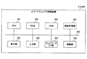
次に、スマートウィンドウ制御装置310、320のハードウェア構成について説明する。図5は、スマートウィンドウ制御装置のハードウェア構成の一例を示す図である。図5に示すように、スマートウィンドウ制御装置310、320は、CPU(Central Processing Unit)501、ROM(Read Only Memory)502、RAM(Random Access Memory)503を有する。CPU501、ROM502、RAM503は、いわゆるコンピュータを形成する。また、スマートウィンドウ制御装置310、320は、補助記憶部504、表示部505、入力部506、ネットワークI/F(Interface)部507、接続部508を有する。なお、スマートウィンドウ制御装置310、320の各ハードウェアは、バス509を介して相互に接続されている。
<Smart window control device>
Next, the hardware configurations of the smart
CPU501は、補助記憶部504にインストールされている各種プログラム(例えば、スマートウィンドウ制御プログラム等)を実行するデバイスである。ROM502は、不揮発性メモリである。ROM502は、補助記憶部504にインストールされている各種プログラムをCPU501が実行するために必要な各種プログラムやデータ等を格納する、主記憶デバイスとして機能する。具体的には、ROM502はBIOS(Basic Input/Output System)やEFI(Extensible Firmware Interface)等のブートプログラム等を格納する。
The
RAM503は、DRAM(Dynamic Random Access Memory)やSRAM(Static Random Access Memory)等の揮発性メモリである。RAM503は、補助記憶部504にインストールされている各種プログラムがCPU501によって実行される際に展開される作業領域を提供する、主記憶デバイスとして機能する。
The
補助記憶部504は、各種プログラムや、各種プログラムが実行される際に用いられる情報を格納する補助記憶デバイスである。
The
表示部505は、スマートウィンドウ制御装置310、320の内部状態を表示する、表示デバイスである。入力部506は、スマートウィンドウ制御装置310、320の管理者がスマートウィンドウ制御装置310、320に対して各種指示を入力するための入力デバイスである。
The
ネットワークI/F部507は、外部ネットワーク250と接続する通信デバイスである。接続部508は、LAN240に接続する接続デバイスである。
The network I /
<スマートウィンドウ制御装置の機能構成>
次に、スマートウィンドウ制御装置の機能構成について説明する。なお、スマートウィンドウ制御装置310及びスマートウィンドウ制御装置320は、同様の構成を有していることから、以下では、説明の簡略化のため、スマートウィンドウ制御装置310について説明する。
<Functional configuration of smart window control device>
Next, the functional configuration of the smart window control device will be described. Since the smart
(1)スマートウィンドウ制御装置の生成部の機能構成
はじめに、スマートウィンドウ制御装置310の生成部330の機能構成について説明する。図6は、スマートウィンドウ制御装置の生成部の機能構成の一例を示す図である。
(1) Functional configuration of the generation unit of the smart window control device First, the functional configuration of the
図6に示すように、スマートウィンドウ制御装置310の生成部330は、実測室外温度取得部601、実測室外日射量取得部602、実績透過率取得部603、モデル生成部604、実測室内温度取得部607を有する。
As shown in FIG. 6, the
実測室外温度取得部601は、室外温度センサ414が測定した、過去の実測室外温度の所定時間範囲(例えば、24時間)ごとの遷移データを取得し、モデル生成部604に入力する。
The actual measurement outdoor
実測室外日射量取得部602は、室外日射量センサ412が測定した、過去の実測室外温度の所定時間範囲ごとの遷移データを取得し、モデル生成部604に入力する。
The actual measurement outdoor solar radiation
実績透過率取得部603は、制御部340による過去の制御結果(透過率)の所定時間範囲ごとの遷移データを取得し、モデル生成部604に入力する。
The actual
モデル生成部604は生成部の一例であり、温度遷移予測モデル605と、モデル評価部606とを有する。温度遷移予測モデル605は、機械学習モデルであり、モデル生成部604により、実測室外温度、実測室外日射量、制御結果(透過率)の所定時間範囲の遷移データが入力されることで、所定時間範囲の温度遷移データを出力する。また、温度遷移予測モデル605は、所定時間範囲の温度遷移データを出力したことに応じて、モデル評価部606より、モデルパラメータの変更指示を受け付け、モデルパラメータを変更することで、機械学習を行う。
The
モデル評価部606は、温度遷移予測モデル605により出力された所定時間範囲の温度遷移データと、実測室内温度取得部607より通知された、過去の実測室内温度の所定時間範囲の遷移データとの誤差を算出する。また、モデル評価部606は、算出した誤差に基づいて、温度遷移予測モデル605に対して、モデルパラメータを変更するための変更指示を出力する。
The
実測室内温度取得部607は、室内温度センサ411_1、411_2が測定した、過去の実測室内温度の所定時間範囲の遷移データを取得し、モデル評価部606に通知する。
The actual measurement indoor
(2)スマートウィンドウ制御装置の生成部によるモデル生成処理の流れ
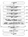
次に、スマートウィンドウ制御装置310の生成部330によるモデル生成処理の流れについて説明する。図7は、スマートウィンドウ制御装置の生成部によるモデル生成処理の流れを示すフローチャートである。
(2) Flow of model generation processing by the generation unit of the smart window control device Next, the flow of model generation processing by the
ステップS701において、実測室外温度取得部601は、過去の実測室外温度の所定時間範囲における遷移データを取得する。
In step S701, the actually measured outdoor
ステップS702において、実測室外日射量取得部602は、過去の実測室外日射量の所定時間範囲における遷移データを取得する。
In step S702, the measured outdoor solar radiation
ステップS703において、実績透過率取得部603は、過去の制御結果の所定時間範囲における遷移データを取得する。
In step S703, the actual
ステップS704において、実測室内温度取得部607は、過去の実測室内温度の所定時間範囲における遷移データを取得する。
In step S704, the measured indoor
ステップS705において、モデル生成部604は、
・過去の実測室外温度の所定時間範囲における遷移データと、
・過去の実測室外日射量の所定時間範囲における遷移データと、
・過去の制御結果の所定時間範囲における遷移データと
を、温度遷移予測モデル605に入力する。これにより、温度遷移予測モデル605では、所定時間範囲における温度遷移データを出力する。
In step S705, the
・ Transition data of past measured outdoor temperature in a predetermined time range and
・ Transition data of past measured outdoor solar radiation in a predetermined time range,
-Transition data in a predetermined time range of past control results is input to the temperature
ステップS706において、モデル評価部606は、出力された所定時間範囲における温度遷移データと、取得された過去の実測室内温度の所定時間範囲の遷移データとの誤差を算出する。また、モデル評価部606は、算出した誤差に基づいて、温度遷移予測モデル605のモデルパラメータを変更する。これにより、モデル生成部604では、温度遷移予測モデル605について、過去の実測室内温度の所定時間範囲の遷移データを正解データとする機械学習を行うことができる。
In step S706, the
ステップS707において、モデル生成部604は、ステップS701からステップS704で取得した全ての遷移データを用いて、温度遷移予測モデル605について機械学習を行ったか否かを判定する。
In step S707, the
ステップS707において、機械学習に用いていない遷移データがあると判定した場合には(ステップS707においてNoの場合には)、ステップS701に戻る。 If it is determined in step S707 that there is transition data that is not used for machine learning (if No in step S707), the process returns to step S701.
一方、ステップS707において、全ての遷移データを用いて温度遷移予測モデル605について機械学習を行ったと判定した場合には(ステップS707においてYesの場合には)、ステップS708に進む。
On the other hand, if it is determined in step S707 that machine learning has been performed on the temperature
ステップS708において、モデル生成部604は、機械学習が完了した学習済みの温度遷移予測モデル605を抽出し、制御部340に設定することで、モデル生成処理を終了する。
In step S708, the
(3)スマートウィンドウ制御装置の制御部の機能構成
次に、スマートウィンドウ制御装置310に含まれる制御部340の機能構成について説明する。図8は、スマートウィンドウ制御装置の制御部の機能構成の一例を示す第1の図である。
(3) Functional Configuration of Control Unit of Smart Window Control Device Next, the functional configuration of the
図8に示すように、スマートウィンドウ制御装置310の制御部340は、空調システム稼働状況取得部801、利用状況取得部802、予測温度取得部803、予測日射量取得部804、透過率パターン入力部805を有する。また、スマートウィンドウ制御装置310の制御部340は、モデル実行部806、設定温度取得部807、判定部808、透過率パターン抽出部809、透過率制御部810を有する。
As shown in FIG. 8, the
空調システム稼働状況取得部801は、空調システム230_1より、ON/OFF情報を取得する。利用状況取得部802は、ビル管理システム210より、空間Aの利用状況を取得する。
The air conditioning system operation
空調システム稼働状況取得部801が、停止中であることを示すOFF情報を取得し、利用状況取得部802が、非利用中であること示す情報を取得した場合、制御部340は予測モードに移行する。
When the air-conditioning system operation
一方、空調システム稼働状況取得部801が、稼働中であることを示すON情報を取得した場合、制御部340は通常モードに移行する。
On the other hand, when the air conditioning system operation
予測温度取得部803は取得部の一例であり、制御部340が予測モードに移行することで、外部ネットワーク250より、予測モード区間中の予測温度推移情報を取得する。予測モード区間とは、制御部340が予測モードに移行した時刻と、次に通常モードに移行する時刻とに基づいて特定される区間である。本実施形態において、予測モード区間は、空調システム230_1の停止区間に等しい。このため、以下では、空調システム230_1が再稼働するタイミングを、"予測モード区間明け"と称する。
The predicted
予測日射量取得部804は取得部の一例であり、制御部340が予測モードに移行することで、外部ネットワーク250より予測モード区間中の予測日射量推移情報を取得する。
The predicted solar radiation
透過率パターン入力部805は、所定時間範囲における透過率の遷移パターンを複数有しており、当該遷移パターンを組み合わせることで、予測モード区間における透過率の遷移パターン(「透過率パターン」と称す)を複数生成する。
The transmittance
モデル実行部806は算出部の一例であり、複数の透過率パターンを、予測モード区間中の予測温度推移情報及び予測日射量推移情報とともに、順次、学習済みの温度遷移予測モデル605に入力し、学習済みの温度遷移予測モデル605を実行させる。これにより、学習済みの温度遷移予測モデル605では、予測モード区間中の温度遷移予測データを順次出力する。
The model execution unit 806 is an example of a calculation unit, and a plurality of transmittance patterns are sequentially input to the trained temperature
設定温度取得部807は、予測モード区間明けの空間Aの温度設定値として、空調システム230_1に設定されている室内設定温度を、空調システム230_1より取得する。
The set
判定部808は、学習済みの温度遷移予測モデル605より順次出力された複数の温度遷移予測データより、予測モード区間明けの温度を抽出し、設定温度取得部807により取得された室内設定温度との誤差を算出する。また、判定部808は、算出した誤差を、透過率パターン抽出部809に通知する。
The
透過率パターン抽出部809は抽出部の一例であり、判定部808より通知された誤差が最小となる透過率パターンを抽出して、透過率制御部810に通知する。
The transmittance pattern extraction unit 809 is an example of the extraction unit, and extracts the transmittance pattern that minimizes the error notified by the
透過率制御部810は、制御部340が予測モードに移行すると、透過率パターン抽出部809から、透過率パターンが通知されるまで待機する。また、透過率制御部810は、透過率パターン抽出部809から透過率パターンが通知されると、当該透過率パターンに従って、スマートウィンドウ120_11、120_12の透過率を制御する。透過率制御部810では、透過率パターンによる制御を、予測モード区間中、継続する。
When the
<モード移行の説明>
次に、スマートウィンドウ制御装置310の制御部340のモード移行について説明する。図9は、スマートウィンドウ制御装置の制御部のモード移行の一例を示す図である。
<Explanation of mode transition>
Next, the mode transition of the
図9に示すように、ビル管理システム210より、空間Aが利用中であることを示す情報が通知され、かつ、空調システム230_1よりON情報が通知されている状態において、制御部340は、通常モードで動作する。図9の例は、制御部340が、"XX月XX日XX時XX分"まで通常モードで動作したことを示している。
As shown in FIG. 9, in a state where the
なお、本実施形態の場合、空調システム230_1は、休前日に空間Aの最終利用者が退出し、空間Aが施錠されることで、停止するように構成されているものとする。 In the case of the present embodiment, the air conditioning system 230_1 is configured to stop when the last user of the space A leaves and the space A is locked on the day before the holiday.
一方で、本実施形態の場合、空調システム230_1が休日明けに再稼働する日時は、(空間Aの利用者が開錠したか否かに関わらず)予め決定されている。図9の例は、空調システム230_1が再稼働する日時が、"YY月YY日YY時YY分"に決定されていることを示している。 On the other hand, in the case of the present embodiment, the date and time when the air conditioning system 230_1 is restarted after the holiday is determined in advance (regardless of whether or not the user of the space A unlocks the lock). The example of FIG. 9 shows that the date and time when the air conditioning system 230_1 is restarted is determined to be "YY month YY day YY hour YY minute".
上述したように、空調システム稼働状況取得部801が取得するOFF情報には、空調システム230_1が再稼働するタイミングも含まれる。このため、制御部340では、OFF情報に基づいて"XX月XX日XX時XX分"(第1の時刻)から所定時間後の"YY月YY日YY時YY分"(第2の時刻)までの区間を、予測モードで動作する予測モード区間として特定することができる。
As described above, the OFF information acquired by the air conditioning system operation
<予測モード区間における動作の具体例>
次に、予測モード区間における制御部340の動作の具体例について説明する。
<Specific example of operation in the prediction mode section>
Next, a specific example of the operation of the
(1)予測モード区間における環境情報の予測値
はじめに、制御部340の予測温度取得部803が取得する、予測モード区間における予測温度推移情報の具体例、及び、制御部340の予測日射量取得部804が取得する、予測モード区間における予測日射量推移情報の具体例について説明する。
(1) Predicted value of environmental information in the predicted mode section First, a specific example of the predicted temperature transition information in the predicted mode section acquired by the predicted
図10は、予測モード区間における環境情報の予測値の具体例を示す図である。図10の例は、"XX月XX日XX時XX分"が金曜日の夜で、"YY月YY日YY時YY分"が月曜日の朝である場合を示している。つまり、休日である土曜日と日曜日の2日間を含む区間が予測モード区間である場合を示している。 FIG. 10 is a diagram showing a specific example of the predicted value of the environmental information in the prediction mode section. The example of FIG. 10 shows the case where "XX month XX day XX hour XX minute" is Friday night and "YY month YY day YY hour YY minute" is Monday morning. That is, the case where the section including the two days of Saturday and Sunday, which are holidays, is the prediction mode section is shown.
このうち、図10(a)は、予測モード区間における予測温度推移情報の具体例を示している。図10(a)の例によれば、予測モードに移行した"XX月XX日XX時XX分"以降、土曜日の朝にかけて気温が下がり、土曜日の日中は気温が上がることが予測されている。また、図10(a)の例によれば、土曜日の夕方以降日曜日の朝にかけて、気温が下がり日曜日の日中は再び気温が上がることが予測されている。更に、日曜日の夕方以降月曜日の朝にかけて、気温が下がることが予測されている。 Of these, FIG. 10A shows a specific example of the predicted temperature transition information in the prediction mode section. According to the example of FIG. 10A, it is predicted that the temperature will decrease until Saturday morning and increase during the daytime on Saturday after "XX month XX day XX hours XX minutes" after the transition to the prediction mode. .. Further, according to the example of FIG. 10A, it is predicted that the temperature will decrease from Saturday evening to Sunday morning and will rise again during the daytime on Sunday. In addition, temperatures are expected to drop from Sunday evening to Monday morning.
なお、図10(a)の例によれば、土曜日は日曜日と比較して、最低気温は低いが最高気温は高くなると予測されている。 According to the example of FIG. 10A, it is predicted that the minimum temperature is lower but the maximum temperature is higher on Saturday than on Sunday.
図10(b)は、予測モード区間における予測日射量推移情報の具体例を示している。図10(b)の例によれば、予測モードに移行した"XX月XX日XX時XX分"以降、土曜日の朝までの間は日射量がゼロで、土曜日の日中は晴れのため日射量が高くなることが予測されている。また、図10(b)の例によれば、日曜日の日中は曇りのため、土曜日の日中と比較して日射量が低くなることが予測されている。 FIG. 10B shows a specific example of the predicted solar radiation amount transition information in the prediction mode section. According to the example of FIG. 10B, the amount of solar radiation is zero from "XX month XX day XX hour XX minute" after the transition to the prediction mode until Saturday morning, and the solar radiation is sunny during the daytime on Saturday. The amount is expected to be high. Further, according to the example of FIG. 10B, since it is cloudy during the daytime on Sunday, it is predicted that the amount of solar radiation will be lower than that during the daytime on Saturday.
(2)予測モード区間における温度遷移予測
次に、制御部340のモデル実行部806が学習済みの温度遷移予測モデル605を実行させることで算出する、予測モード区間における空間Aの温度遷移予測データの具体例について説明する。図11は、予測モード区間における温度遷移予測データの一例を示す図である。上述したとおり、モデル実行部806は、予測モード区間における予測温度推移情報、予測日射量推移情報、複数の透過率パターンを、学習済みの温度遷移予測モデル605に順次入力することで、学習済みの温度遷移予測モデル605を実行させる。これにより、学習済みの温度遷移予測モデル605では、予測モード区間における、空間Aの温度遷移予測データを順次出力する。
(2) Temperature Transition Prediction in Prediction Mode Section Next, the temperature transition prediction data of the space A in the prediction mode section calculated by the model execution unit 806 of the
図11において、点線1110は、空間Aの温度が最も高い状態で遷移する透過率パターンを入力した場合の、空間Aの温度遷移予測データを示している。また、点線1120は、空間Aの温度が最も低い状態で遷移する透過率パターンを入力した場合の、空間Aの温度遷移予測データを示している。
In FIG. 11, the dotted
このように、予測モード区間において用いる透過率パターンによって、"YY月YY日YY時YY分"における空間Aの温度には、矢印に示すばらつきが発生する。ここで、図11の例では、空調システム230_1に、予測モード区間明け("YY月YY日YY時YY分")の空間Aの室内設定温度として、破線で示す温度が設定されているものとする。 As described above, the temperature of the space A in the "YY month YY day YY hour YY minute" varies depending on the transmittance pattern used in the prediction mode section. Here, in the example of FIG. 11, it is assumed that the temperature indicated by the broken line is set in the air conditioning system 230_1 as the indoor set temperature of the space A at the end of the prediction mode section (“YY month YY day YY hour YY minute”). To do.
このため、制御部340の透過率パターン抽出部809では、予測モード区間明け("YY月YY日YY時YY分")の空間Aの温度が、破線で示す設定温度に最も近くなる温度遷移予測データ(実線1130)に対応する透過率パターンを抽出する。
Therefore, in the transmittance pattern extraction unit 809 of the
かかる透過率パターンを用いてスマートウィンドウ120_11、120_12の透過率を制御することで、予測モード区間明け("YY月YY日YY時YY分")の空間Aの温度を、室内設定温度に一致させることが可能となる。この結果、空調システム230_1を再稼働させた際の空調システム230_1の負荷を下げることができる。 By controlling the transmittance of the smart windows 120_11 and 120_12 using such a transmittance pattern, the temperature of the space A at the end of the prediction mode section ("YY month YY day YY hour YY minute") is made to match the indoor set temperature. It becomes possible. As a result, the load on the air conditioning system 230_1 when the air conditioning system 230_1 is restarted can be reduced.
<予測モードにおける透過率制御処理>
次に、予測モードにおける透過率制御処理の流れについて説明する。図12は、予測モードにおける透過率制御処理の流れを示す第1のフローチャートである。
<Transmittance control processing in prediction mode>
Next, the flow of the transmittance control process in the prediction mode will be described. FIG. 12 is a first flowchart showing the flow of the transmittance control process in the prediction mode.
ステップS1201において、空調システム稼働状況取得部801は、空調システム230_1より通知されるON/OFF情報を監視し、利用状況取得部802は、ビル管理システム210より通知される空間Aの利用状況を監視する。これにより、制御部340では、通常モードで動作するか予測モードで動作するかを決定する。一方、予測温度取得部803、予測日射量取得部804、透過率制御部810では、制御部340のモード移行を監視し、制御部340が、通常モードから予測モードに移行したか否かを判定する。
In step S1201, the air conditioning system operation
ステップS1201において、通常モードから予測モードに移行していないと判定した場合には(ステップS1201においてNoの場合には)、通常モードから予測モードに移行したと判定するまで待機する。 If it is determined in step S1201 that the mode has not changed from the normal mode to the prediction mode (if No in step S1201), it waits until it is determined that the mode has changed from the normal mode to the prediction mode.
一方、ステップS1201において、通常モードから予測モードに移行したと判定した場合には(ステップS1201においてYesの場合には)、ステップS1202に進む。 On the other hand, if it is determined in step S1201 that the mode has shifted from the normal mode to the prediction mode (yes in step S1201), the process proceeds to step S1202.
ステップS1202において、予測温度取得部803は、外部ネットワーク250より、予測モード区間における予測温度推移情報を取得する。また、予測日射量取得部804は、外部ネットワーク250より、予測モード区間における予測温度推移情報を取得する。
In step S1202, the predicted
ステップS1203において、設定温度取得部807は、予測モード区間明けの空間Aの室内設定温度として、空調システム230に設定された室内設定温度を取得する。
In step S1203, the set
ステップS1204において、透過率パターン入力部805は、複数の透過率パターンのうちのいずれかを選択して、モデル実行部806に通知する。
In step S1204, the transmittance
ステップS1205において、予測温度取得部803は、取得した予測温度推移情報をモデル実行部806に通知する。また、予測日射量取得部804は、取得した予測日射量推移情報をモデル実行部806に通知する。更に、モデル実行部806は、予測温度推移情報、予測日射量推移情報、透過率パターンを温度遷移予測モデル605に入力することで、温度遷移予測モデル605を実行させ、温度遷移予測データを算出する。
In step S1205, the predicted
ステップS1206において、判定部808は、モデル実行部806により算出された温度遷移予測データの予測モード区間明けの温度と、設定温度取得部807が取得した、予測モード区間明けの空間Aの室内設定温度との誤差を算出する。
In step S1206, the
ステップS1207において、透過率パターン入力部805は、全ての透過率パターンについて、温度遷移予測データを算出したか否かを判定する。ステップS1207において、温度遷移予測データを算出していない透過率パターンがあると判定した場合には(ステップS1207においてNoの場合には)、ステップS1204に戻る。
In step S1207, the transmittance
一方、ステップS1207において、全ての透過率パターンについて、温度遷移予測データを算出したと判定した場合には、ステップS1208に進む。 On the other hand, if it is determined in step S1207 that the temperature transition prediction data has been calculated for all the transmittance patterns, the process proceeds to step S1208.
ステップS1208において、透過率パターン抽出部809は、誤差が最小となる透過率パターンを抽出し、透過率制御部810に通知する。
In step S1208, the transmittance pattern extraction unit 809 extracts the transmittance pattern that minimizes the error and notifies the
ステップS1209において、透過率制御部810は、透過率パターン抽出部809より通知された透過率パターンを用いて、スマートウィンドウの透過率の制御を開始する。
In step S1209, the
ステップS1210において、透過率制御部810は、予測モードが継続しているか否かを判定する。ステップS1210において、予測モードが継続していると判定した場合には(ステップS1210においてYesの場合には)、ステップS1209に戻る。
In step S1210, the
一方、ステップS1210において、予測モードから通常モードに移行したと判定した場合には(ステップS1210においてNoの場合には)、予測モードにおける透過率制御処理を終了する。 On the other hand, if it is determined in step S1210 that the mode has changed from the prediction mode to the normal mode (No in step S1210), the transmittance control process in the prediction mode is terminated.
<まとめ>
以上の説明から明らかなように、第1の実施形態に係るスマートウィンドウ制御装置は、
・空調システムにより室内設定温度に応じて温度制御が行われる空間の窓部に設けられた、スマートウィンドウの透過率を制御する。
・空調システムが停止されてから再稼働されるまでの停止区間を予測モード区間とし、当該区間における予測温度推移情報及び予測日射量推移情報を、外部ネットワークより取得する。
・過去の実測室外温度と、過去の実測室外日射量と、過去の実績透過率とに基づいて、所定時間範囲における空間の温度遷移を予測する温度遷移予測モデルを生成する。
・生成した温度遷移予測モデルに、複数の透過率パターンを、予測温度推移情報及び予測日射量推移情報とともに順次入力することで、予測モード区間における複数の温度遷移予測データを算出する。
・算出した複数の温度遷移予測データのうち、予測モード区間明けの温度が、予測モード区間明けの室内設定温度に最も近い透過率パターンを抽出し、当該透過率パターンを用いて、予測モード区間におけるスマートウィンドウの透過率を制御する。
<Summary>
As is clear from the above description, the smart window control device according to the first embodiment is
-Controls the transmittance of the smart window provided in the window of the space where the temperature is controlled according to the indoor set temperature by the air conditioning system.
-The stop section from the stop to the restart of the air conditioning system is set as the prediction mode section, and the predicted temperature transition information and the predicted solar radiation amount transition information in the section are acquired from the external network.
-Generate a temperature transition prediction model that predicts the temperature transition in space within a predetermined time range based on the past measured outdoor temperature, the past measured outdoor solar radiation amount, and the past actual transmittance.
-By sequentially inputting a plurality of transmittance patterns together with the predicted temperature transition information and the predicted solar radiation amount transition information into the generated temperature transition prediction model, a plurality of temperature transition prediction data in the prediction mode section are calculated.
-Of the plurality of calculated temperature transition prediction data, the transmittance pattern in which the temperature after the prediction mode section is closest to the indoor set temperature after the prediction mode section is extracted, and the transmittance pattern is used in the prediction mode section. Control the transparency of smart windows.
このように、第1の実施形態に係るスマートウィンドウ制御装置では、予測モード区間明けの温度が、予測モード区間明けの室内設定温度に近づくように、予測モード区間中の空間の温度を、予測した温度遷移に基づいて遷移させる。これにより、第1の実施形態に係るスマートウィンドウ制御装置によれば、透過率を制御してから実際に建物内の温度が変化するまでのタイムラグの影響を低減させることができる。 As described above, in the smart window control device according to the first embodiment, the temperature of the space in the prediction mode section is predicted so that the temperature after the prediction mode section approaches the indoor set temperature after the prediction mode section. The transition is based on the temperature transition. As a result, according to the smart window control device according to the first embodiment, it is possible to reduce the influence of the time lag from the control of the transmittance to the actual change in the temperature inside the building.
この結果、第1の実施形態に係るスマートウィンドウ制御装置によれば、予測モード区間明けに空調システムを再稼働させた際の空調システムの負荷を下げることが可能となる。 As a result, according to the smart window control device according to the first embodiment, it is possible to reduce the load on the air conditioning system when the air conditioning system is restarted after the prediction mode section.
[第2の実施形態]
上記第1の実施形態では、温度遷移予測モデル605により算出された温度遷移予測データに基づいて、透過率パターンを抽出し、抽出した透過率パターンに基づいて、予測モード区間中のスマートウィンドウの透過率を制御する構成とした。
[Second Embodiment]
In the first embodiment, a transmittance pattern is extracted based on the temperature transition prediction data calculated by the temperature
これに対して、第2の実施形態では、温度遷移予測モデル605により算出された温度遷移予測データに従って、予測モード区間中の空間の温度が遷移するように、スマートウィンドウの透過率を制御する。以下、第2の実施形態について、上記第1の実施形態との相違点を中心に説明する。
On the other hand, in the second embodiment, the transmittance of the smart window is controlled so that the temperature of the space in the prediction mode section changes according to the temperature transition prediction data calculated by the temperature
<スマートウィンドウ制御装置の制御部の機能構成>
はじめに、スマートウィンドウ制御装置310の制御部340の機能構成について説明する。図13は、スマートウィンドウ制御装置の制御部の機能構成の一例を示す第2の図である。図8との相違点は、図13の場合、温度遷移パターン抽出部1301、実測室内温度取得部1302、透過率制御部1303を有する点である。
<Functional configuration of the control unit of the smart window control device>
First, the functional configuration of the
温度遷移パターン抽出部1301は抽出部の一例であり、複数の透過率パターンが温度遷移予測モデル605に入力されることで算出された、それぞれの温度遷移予測データと、室内設定温度との誤差とを、判定部808より取得する。
The temperature transition
また、温度遷移パターン抽出部1301は、取得した誤差が最小となる温度遷移予測データを抽出し、温度遷移パターンとして透過率制御部1303に通知する。
Further, the temperature transition
実測室内温度取得部1302は、空調装置410より、現在時刻の実測室内温度を取得し、透過率制御部1303に通知する。
The actual measurement room
透過率制御部1303は、制御部340が予測モードに移行すると、温度遷移パターン抽出部1301から、温度遷移パターンが通知されるまで待機する。また、透過率制御部1303は、温度遷移パターン抽出部1301から温度遷移パターンが通知されると、当該温度遷移パターンに従って、スマートウィンドウ120_11、120_12の透過率を制御する。具体的には、透過率制御部1303は、現在時刻の実測室内温度と、温度遷移パターンにおける現在時刻の温度とを比較し、現在時刻の実測室内温度の方が、温度遷移パターンにおける現在時刻の温度よりも高い場合には、透過率を下げるように制御する。また、透過率制御部1303は、現在時刻の実測室内温度の方が、温度遷移パターンにおける現在時刻の温度よりも低い場合には、透過率を上げるように制御する。
When the
<予測モード区間における動作の具体例>
次に、予測モード区間における制御部340の動作の具体例について説明する。図14は、予測モード区間における実測室内温度の具体例を示す図である。図14において、"XX月XX日XX時XX分"から"YY月YY日YY時YY分"までの間は、予測モード区間である。また、図14において、実線1130は、温度遷移パターン抽出部1301より通知された温度遷移パターンである(予測モード区間明けの温度1100が、予測モード区間明けの室内設定温度に一致する温度遷移パターンである)。
<Specific example of operation in the prediction mode section>
Next, a specific example of the operation of the
一方、太実線1400は、予測モードに移行してから現在時刻までの実測室内温度である。また、符号1401は、現在時刻における実測室内温度を示しており、符号1411は、温度遷移パターン(実線1130)における現在時刻の温度を示している。図14の例では、現在時刻における実測室内温度(符号1401)が、温度遷移パターン(実線1130)における現在時刻の温度(符号1411)よりも低いため、透過率制御部1303では、透過率を上げるように制御する。
On the other hand, the thick
これにより、透過率制御部1303では、予測モード区間中の空間Aの温度を、温度遷移パターン(実線1130)に従って遷移させることが可能となる。そして、予測モード区間明けの温度を、予測モード区間明けの室内設定温度に一致させることが可能となる。
As a result, the
この結果、予測区間明けに空調システムを再稼働させた際の空調システムの負荷を下げることができる。 As a result, the load on the air conditioning system when the air conditioning system is restarted after the prediction interval can be reduced.
<予測モードにおける透過率制御処理>
次に、予測モードにおける透過率制御処理の流れについて説明する。図15は、予測モードにおける透過率制御処理の流れを示す第2のフローチャートである。図12に示したフローチャートとの相違点は、ステップS1501〜ステップS1505である。
<Transmittance control processing in prediction mode>
Next, the flow of the transmittance control process in the prediction mode will be described. FIG. 15 is a second flowchart showing the flow of the transmittance control process in the prediction mode. The difference from the flowchart shown in FIG. 12 is steps S1501 to S1505.
ステップS1501において、温度遷移パターン抽出部1301は、誤差が最小となる温度遷移パターンを抽出し、透過率制御部1303に通知する。
In step S1501, the temperature transition
ステップS1502において、透過率制御部1303は、デフォルトの透過率で、スマートウィンドウの透過率の制御を開始する。
In step S1502, the
ステップS1503において、透過率制御部1303は、所定の制御周期が経過したか否かを判定する。ステップS1503において、所定の制御周期が経過していないと判定した場合には(ステップS1503においてNoの場合には)、所定の制御周期が経過するまで待機する。
In step S1503, the
一方、ステップS1503において、所定の制御周期が経過したと判定した場合には(ステップS1503においてYesの場合には)、ステップS1504に進む。 On the other hand, if it is determined in step S1503 that the predetermined control cycle has elapsed (yes in step S1503), the process proceeds to step S1504.
ステップS1504において、透過率制御部1303は、実測室内温度取得部1302が取得した現在時刻における実測室内温度と、温度遷移パターンにおける現在時刻の温度とを比較し、比較結果に応じて透過率を変更する。
In step S1504, the
ステップS1505において、透過率制御部1303は、予測モードが継続しているか否かを判定する。ステップS1505において、予測モードが継続していると判定した場合には(ステップS1505においてYesの場合には)、ステップS1503に戻る。
In step S1505, the
一方、ステップS1505において、予測モードから通常モードに移行した判定した場合には(ステップS1505においてNoの場合には)、予測モードにおける透過率制御処理を終了する。 On the other hand, if it is determined in step S1505 that the mode has changed from the prediction mode to the normal mode (No in step S1505), the transmittance control process in the prediction mode is terminated.
<まとめ>
以上の説明から明らかなように、第2の実施形態に係るスマートウィンドウ制御装置は、
・空調システムにより室内設定温度に応じて温度制御が行われる空間の窓部に設けられた、スマートウィンドウの透過率を制御する。
・空調システムが停止されてから再稼働されるまでの停止区間を予測モード区間とし、当該区間における予測温度推移情報及び予測日射量推移情報を、外部ネットワークより取得する。
・過去の実測室外温度と、過去の実測室内日射量と、過去の実績透過率とに基づいて、所定時間範囲における空間の温度遷移を予測する温度遷移予測モデルを生成する。
・生成した温度遷移予測モデルに、複数の透過率パターンを、予測温度推移情報及び予測日射量推移情報とともに順次入力することで、予測モード区間における複数の温度遷移予測データを算出する。
・算出した複数の温度遷移予測データのうち、予測モード区間明けの温度が、予測モード区間明けの室内設定温度に最も近い温度遷移予測データを、温度遷移パターンとして抽出する。また、当該温度遷移パターンと実測室内温度とを用いて、予測モード区間におけるスマートウィンドウの透過率を制御する。
<Summary>
As is clear from the above description, the smart window control device according to the second embodiment is
-Controls the transmittance of the smart window provided in the window of the space where the temperature is controlled according to the indoor set temperature by the air conditioning system.
-The stop section from the stop to the restart of the air conditioning system is set as the prediction mode section, and the predicted temperature transition information and the predicted solar radiation amount transition information in the section are acquired from the external network.
-Generate a temperature transition prediction model that predicts the temperature transition in space within a predetermined time range based on the past measured outdoor temperature, the past measured indoor solar radiation amount, and the past actual transmittance.
-By sequentially inputting a plurality of transmittance patterns together with the predicted temperature transition information and the predicted solar radiation amount transition information into the generated temperature transition prediction model, a plurality of temperature transition prediction data in the prediction mode section are calculated.
-Of the plurality of calculated temperature transition prediction data, the temperature transition prediction data in which the temperature after the prediction mode section is closest to the indoor set temperature after the prediction mode section is extracted as the temperature transition pattern. In addition, the transmittance of the smart window in the prediction mode section is controlled by using the temperature transition pattern and the measured room temperature.
このように、第2の実施形態に係るスマートウィンドウ制御装置では、予測モード区間明けの温度が、予測モード区間明けの室内設定温度に近づくように、予測モード区間中の空間の温度を、温度遷移パターンに基づいて遷移させる。これにより、第2の実施形態に係るスマートウィンドウ制御装置によれば、透過率を制御してから実際に建物内の温度が変化するまでのタイムラグの影響を低減させることができる。 As described above, in the smart window control device according to the second embodiment, the temperature of the space in the prediction mode section is changed so that the temperature after the prediction mode section approaches the indoor set temperature after the prediction mode section. Make a transition based on the pattern. As a result, according to the smart window control device according to the second embodiment, it is possible to reduce the influence of the time lag from the control of the transmittance to the actual change in the temperature inside the building.
この結果、第2の実施形態に係るスマートウィンドウ制御装置によれば、予測モード区間明けに空調システムを再稼働させた際の空調システムの負荷を下げることが可能となる。 As a result, according to the smart window control device according to the second embodiment, it is possible to reduce the load on the air conditioning system when the air conditioning system is restarted after the prediction mode section.
[第3の実施形態]
上記第1及び第2の実施形態では、スマートウィンドウ制御装置が予測モードで動作する場合について説明した。これに対して、第3の実施形態では、スマートウィンドウ制御装置が通常モードで動作する場合について説明する。以下、第3の実施形態について、上記第1及び第2の実施形態との相違点を中心に説明する。
[Third Embodiment]
In the first and second embodiments described above, the case where the smart window control device operates in the prediction mode has been described. On the other hand, in the third embodiment, the case where the smart window control device operates in the normal mode will be described. Hereinafter, the third embodiment will be described focusing on the differences from the first and second embodiments.
<通常モード区間における動作の具体例>
はじめに、通常モード区間における制御部340の動作の具体例について説明する。図16は、通常モード区間における温度遷移予測データの一例を示す第1の図である。図16の例では、"AA月AA日AA時AA分"(第1の時刻)から所定時間後の"BB月BB日BB時BB分"(第2の時刻)までを通常モード区間としている。
<Specific example of operation in the normal mode section>
First, a specific example of the operation of the
第3の実施形態において、モデル実行部806は、通常モード区間における予測温度推移情報、予測日射量推移情報、複数の透過率パターンを、学習済みの温度遷移予測モデル605に順次入力することで、学習済みの温度遷移予測モデル605を実行させる。これにより、学習済みの温度遷移予測モデル605では、通常モード区間における、空間Aの温度遷移予測データを順次出力する。
In the third embodiment, the model execution unit 806 sequentially inputs the predicted temperature transition information, the predicted solar radiation amount transition information, and a plurality of transmittance patterns in the normal mode section into the trained temperature
図16において、点線1110は、空間Aの温度が最も高い状態で遷移する透過率パターンを入力した場合の、空間Aの温度遷移予測データを示している。また、点線1120は、空間Aの温度が最も低い状態で遷移する透過率パターンを入力した場合の、空間Aの温度予測データを示している。
In FIG. 16, the dotted
このように、通常モード区間において用いる透過率パターンによって、通常モード区間における空間Aの温度遷移には、ばらつきが発生する。制御部340の透過率パターン抽出部809では、このうち、室内設定温度との差分の累積値(例えば、図16のグレー領域の面積)が最小となる温度遷移予測データ(実線1600)に対応する透過率パターンを抽出する。室内設定温度との差分の累積値が最小の場合、空調システム230_1の稼働中の区間の負荷を最小にすることができるからである。
As described above, the temperature transition of the space A in the normal mode section varies depending on the transmittance pattern used in the normal mode section. The transmittance pattern extraction unit 809 of the
<通常モードにおける透過率制御処理>
次に、通常モードにおける透過率制御処理の流れについて説明する。図17は、通常モードにおける透過率制御処理の流れを示す第1のフローチャートである。図12に示した、予測モードにおける透過率制御処理との相違点は、ステップS1701〜S1703、S1704、S1705である。
<Transmittance control processing in normal mode>
Next, the flow of the transmittance control process in the normal mode will be described. FIG. 17 is a first flowchart showing the flow of the transmittance control process in the normal mode. The difference from the transmittance control process in the prediction mode shown in FIG. 12 is steps S1701 to S1703, S1704, and S1705.
ステップS1701において、空調システム稼働状況取得部801は、空調システム230_1より通知されるON/OFF情報を監視し、利用状況取得部802は、ビル管理システム210より通知される空間Aの利用状況を監視する。これにより、制御部340では、通常モードで動作するか予測モードで動作するかを決定する。一方、予測温度取得部803、予測日射量取得部804、透過率制御部810では、制御部340のモード移行を監視し、制御部340が、予測モードから通常モードに移行したか否かを判定する。
In step S1701, the air conditioning system operation
ステップS1701において、予測モードから通常モードに移行していないと判定した場合には(ステップS1701においてNoの場合には)、予測モードから通常モードに移行したと判定するまで待機する。 If it is determined in step S1701 that the prediction mode has not shifted to the normal mode (if No in step S1701), it waits until it is determined that the prediction mode has shifted to the normal mode.
一方、ステップS1701において、予測モードから通常モードに移行したと判定した場合には(ステップS1701においてYesの場合には)、ステップS1702に進む。 On the other hand, if it is determined in step S1701 that the mode has changed from the prediction mode to the normal mode (yes in step S1701), the process proceeds to step S1702.
ステップS1702において、予測温度取得部803は、外部ネットワーク250より、通常モード区間における予測温度推移情報を取得する。また、予測日射量取得部804は、外部ネットワーク250より、通常モード区間における予測温度推移情報を取得する。
In step S1702, the predicted
ステップS1703において、設定温度取得部807は、通常モード区間における空間Aの室内設定温度として、空調システム230に設定された室内設定温度を取得する。
In step S1703, the set
ステップS1704において、判定部808は、モデル実行部806により算出された温度遷移予測データの通常モード区間における温度と、設定温度取得部807が取得した、通常モード区間における空間Aの室内設定温度との誤差の累積値を算出する。
In step S1704, the
ステップS1705において、透過率パターン抽出部809は、誤差の累積値が最小となる透過率パターンを抽出し、透過率制御部810に通知する。
In step S1705, the transmittance pattern extraction unit 809 extracts the transmittance pattern that minimizes the cumulative value of the error and notifies the
<まとめ>
以上の説明から明らかなように、第3の実施形態に係るスマートウィンドウ制御装置は、
・空調システムにより室内設定温度に応じて温度制御が行われる空間の窓部に設けられた、スマートウィンドウの透過率を制御する。
・空調システムが稼働中の区間を通常モード区間とし、当該区間における予測温度推移情報及び予測日射量推移情報を、外部ネットワークより取得する。
・過去の実測室外温度と、過去の実測室外日射量と、過去の実績透過率とに基づいて、所定時間範囲における空間の温度遷移を予測する温度遷移予測モデルを生成する。
・生成した温度予測モデルに、複数の透過率パターンを、予測温度推移情報及び予測日射量推移情報とともに順次入力することで、通常モード区間における複数の温度遷移予測データを算出する。
・算出した複数の温度遷移予測データのうち、通常モード区間の温度と、通常モード区間の室内設定温度との差分の累積値が、最小となる透過率パターンを抽出し、当該透過率パターンを用いて、通常モード区間におけるスマートウィンドウの透過率を制御する。
<Summary>
As is clear from the above description, the smart window control device according to the third embodiment is
-Controls the transmittance of the smart window provided in the window of the space where the temperature is controlled according to the indoor set temperature by the air conditioning system.
-The section in which the air conditioning system is operating is set as the normal mode section, and the predicted temperature transition information and the predicted solar radiation amount transition information in the section are acquired from the external network.
-Generate a temperature transition prediction model that predicts the temperature transition in space within a predetermined time range based on the past measured outdoor temperature, the past measured outdoor solar radiation amount, and the past actual transmittance.
-By sequentially inputting a plurality of transmittance patterns together with the predicted temperature transition information and the predicted solar radiation amount transition information into the generated temperature prediction model, a plurality of temperature transition prediction data in the normal mode section is calculated.
-Of the plurality of calculated temperature transition prediction data, the transmittance pattern in which the cumulative value of the difference between the temperature in the normal mode section and the indoor set temperature in the normal mode section is the minimum is extracted, and the transmittance pattern is used. Therefore, the transmittance of the smart window in the normal mode section is controlled.
このように、第3の実施形態に係るスマートウィンドウ制御装置では、通常モード区間中の温度が、通常モード区間中の室内設定温度に近づくように、通常モード区間中の空間の温度を、予測した温度遷移に基づいて遷移させる。これにより、第3の実施形態に係るスマートウィンドウ制御装置によれば、透過率を制御してから実際に建物内の温度が変化するまでのタイムラグの影響を低減させることができる。 As described above, in the smart window control device according to the third embodiment, the temperature of the space in the normal mode section is predicted so that the temperature in the normal mode section approaches the indoor set temperature in the normal mode section. The transition is based on the temperature transition. As a result, according to the smart window control device according to the third embodiment, it is possible to reduce the influence of the time lag from the control of the transmittance to the actual change in the temperature inside the building.
この結果、第3の実施形態に係るスマートウィンドウ制御装置によれば、空調システムの稼働中の区間の負荷を最小にすることができる。 As a result, according to the smart window control device according to the third embodiment, the load on the operating section of the air conditioning system can be minimized.
[第4の実施形態]
上記第3の実施形態では、通常モード区間における空間Aの室内設定温度として、空調システム230に設定された室内設定温度を用いるものとして説明した。しかしながら、通常モード区間における空間Aの室内設定温度として、空調システム230に設定された室内設定温度を修正した、修正後の室内設定温度を用いてもよい。
[Fourth Embodiment]
In the third embodiment, it has been described that the indoor set temperature set in the
例えば、空間Aの温度を上昇させるほどの多数の人が、所定の日時に流入することが予め分かっている場合にあっては、当該所定の日時の室内設定温度を、下げる方向に修正したうえで、スマートウィンドウの透過率を制御してもよい。 For example, if it is known in advance that a large number of people will flow in at a predetermined date and time to raise the temperature of the space A, the indoor set temperature at the predetermined date and time is corrected to be lowered. You may control the transparency of the smart window.
つまり、空間内の温度に影響を与えるほどの内部環境情報の変化が、所定の日時に発生することが予め分かっている場合には、当該所定の日時の室内設定温度を修正することで、結果的に室内Aの温度を一定に保つ。これにより、内部環境情報の変化に関わらず、空調システムの稼働中の区間の負荷を下げることができる。以下、第4の実施形態について、上記第1乃至第3の実施形態との相違点を中心に説明する。 That is, if it is known in advance that a change in the internal environment information that affects the temperature in the space will occur at a predetermined date and time, the result can be obtained by correcting the indoor set temperature at the predetermined date and time. The temperature of the room A is kept constant. As a result, the load on the operating section of the air conditioning system can be reduced regardless of changes in the internal environmental information. Hereinafter, the fourth embodiment will be described focusing on the differences from the first to third embodiments.
<環境情報の予測値の説明>
はじめに環境情報の予測値について説明する。上記第1乃至第3の実施形態では、空間A内の温度に影響を与える環境情報の予測値として、予測温度推移情報と、予測日射量推移情報を例示した。しかしながら、空間A内の温度に影響を与える環境情報の予測値には、これら外部の環境情報の予測値に限定されず、内部の環境情報の予測値も含まれる。
<Explanation of predicted values of environmental information>
First, the predicted values of environmental information will be explained. In the first to third embodiments, the predicted temperature transition information and the predicted solar radiation amount transition information are exemplified as the predicted values of the environmental information affecting the temperature in the space A. However, the predicted value of the environmental information that affects the temperature in the space A is not limited to the predicted value of the external environmental information, but also includes the predicted value of the internal environmental information.
内部の環境情報の予測値とは、例えば、空間Aへの人の流入や、空間Aへの外気の流入、空間Aからの内気の流出等、通常モード区間中に空間Aの温度に影響を与える空間A内の事象を予測した予測値である。 The predicted value of the internal environmental information affects the temperature of the space A during the normal mode section, such as the inflow of a person into the space A, the inflow of the outside air into the space A, and the outflow of the inside air from the space A. It is a predicted value that predicts an event in the given space A.
図18は、環境情報の予測値を示す図である。図18に示すように、第4の実施形態では、第1乃至第3の実施形態における環境情報の予測値(予測温度推移情報、予測日射量推移情報)が、"外部環境情報の予測値"に対応している。 FIG. 18 is a diagram showing predicted values of environmental information. As shown in FIG. 18, in the fourth embodiment, the predicted values of the environmental information (predicted temperature transition information, predicted solar radiation amount transition information) in the first to third embodiments are "predicted values of external environmental information". It corresponds to.
一方、通常モード区間中に空間A、空間Bの温度に影響を与える空間A、B内の事象を予測した予測値を、内部環境情報の予測値と称する。 On the other hand, the predicted value that predicts the events in the spaces A and B that affect the temperature of the spaces A and B during the normal mode section is referred to as the predicted value of the internal environment information.
<スマートウィンドウ制御装置の機能構成>
次に、スマートウィンドウ制御装置の機能構成について説明する。図19は、スマートウィンドウ制御装置の制御部の機能構成の一例を示す第2の図である。
<Functional configuration of smart window control device>
Next, the functional configuration of the smart window control device will be described. FIG. 19 is a second diagram showing an example of the functional configuration of the control unit of the smart window control device.
図8に示した機能構成との相違点は、図19の場合、設定温度取得部1901の機能が、図8の設定温度取得部807の機能とは異なる点である。
The difference from the functional configuration shown in FIG. 8 is that, in the case of FIG. 19, the function of the set
設定温度取得部1901は修正部の一例である。設定温度取得部1901は、通常モード区間中の空間Aの室内設定温度として、空調システム230_1に設定されている室内設定温度を、空調システム230_1より取得する。また、設定温度取得部1901は、通常モード区間中の空間Aの内部環境情報の予測値を、外部ネットワーク250より取得する。更に、設定温度取得部1901は、取得した内部環境情報の予測値に基づいて、取得した室内設定温度を修正し、修正後の室内設定温度を判定部808に通知する。
The set
<通常モード区間における温度遷移予測>
次に、制御部340のモデル実行部806が学習済みの温度遷移予測モデル605を実行させることで算出する、通常モード区間における空間Aの温度遷移予測データの具体例について説明する。図20は、通常モード区間における温度遷移予測データの一例を示す第2の図である。
<Temperature transition prediction in normal mode section>
Next, a specific example of the temperature transition prediction data of the space A in the normal mode section, which is calculated by executing the trained temperature
このうち、図20(a)は、通常モード区間における内部環境情報の予測値の一例であり、ここでは、通常モード区間中に空間Aに流入する人の数を示している。図20(a)の例に示すように、"AA月AA日AA時AA分"(第1の時刻)から所定時間後の"CC月CC日CC時CC分"(第2の時刻)までの間に空間Aに流入する人の数の最大値は一定であることが予測されている(符号2001〜符号2003参照)。
Of these, FIG. 20A is an example of the predicted value of the internal environment information in the normal mode section, and here shows the number of people flowing into the space A during the normal mode section. As shown in the example of FIG. 20A, from "AA month AA day AA hour AA minute" (first time) to "CC month CC day CC hour CC minute" (second time) after a predetermined time. It is predicted that the maximum value of the number of people flowing into the space A during the period is constant (see
一方、"CC月CC日CC時CC分"から"DD月DD日DD時DD分"までの間に空間Aに流入する人の数の最大値は大きく変化することが予測されている(符号2004参照)。 On the other hand, it is predicted that the maximum value of the number of people flowing into the space A will change significantly between "CC month CC day CC hour CC minute" and "DD month DD day DD hour DD minute" (code). See 2004).
図20(b)は、通常モード区間において、内部環境情報が変化したことに起因して変動する、空間Aの温度の変動幅の予測値を示している。図20(b)の例によれば、空間Aに流入する人の数の最大値が、符号2001〜2003に示す値である場合、人の流入に伴う空間Aの温度の変動幅はゼロまたは微小であることが予測されている。
FIG. 20B shows a predicted value of the fluctuation range of the temperature of the space A, which fluctuates due to the change of the internal environment information in the normal mode section. According to the example of FIG. 20B, when the maximum value of the number of people flowing into the space A is the value shown by
一方、空間Aに流入する人の数の最大値が、符号2004に示す値である場合、人の流入に伴って、空間Aの温度が上昇することが予測されている(符号2011参照)。
On the other hand, when the maximum value of the number of people flowing into the space A is the value shown in
図20(c)は、通常モード区間における修正後の室内設定温度と、通常モード区間における温度遷移予測データの一例を示している。図20(c)に示すように、"AA月AA日AA時AA分"から"CC月CC日CC時CC分"までの間は、内部環境情報が変化したことに起因して変動する、空間Aの温度の変動幅の予測値がゼロまたは微小である。このため、設定温度取得部1901では、空調システム230_1に設定されている室内設定温度を、そのまま判定部808に通知する。
FIG. 20C shows an example of the corrected indoor set temperature in the normal mode section and the temperature transition prediction data in the normal mode section. As shown in FIG. 20 (c), the temperature from "AA month AA day AA hour AA minute" to "CC month CC day CC hour CC minute" fluctuates due to changes in internal environmental information. The predicted value of the fluctuation range of the temperature in space A is zero or minute. Therefore, the set
一方、"CC月CC日CC時CC分"から"DD月DD日DD時DD分"までの間は、内部環境情報が変化したことに起因して、空間Aの温度が上昇することが予測されている。このため、設定温度取得部1901では、空調システム230_1に設定されている室内設定温度を、温度の上昇幅に応じて修正し、修正後の室内設定温度を判定部808に通知する(符号2021参照)。
On the other hand, between "CC month CC day CC hour CC minute" and "DD month DD day DD hour DD minute", it is predicted that the temperature of space A will rise due to the change in internal environmental information. Has been done. Therefore, the set
また、図20(c)において、点線1110は、外部環境情報の変化に対して、空間Aの温度が最も高い状態で遷移する透過率パターンを入力した場合の、空間Aの温度遷移予測データを示している。また、点線1120は、外部環境情報の変化に対して、空間Aの温度が最も低い状態で遷移する透過率パターンを入力した場合の、空間Aの温度予測データを示している。
Further, in FIG. 20 (c), the dotted
このように、通常モード区間において用いる透過率パターンによって、通常モード区間における空間Aの温度遷移には、ばらつきが発生する。制御部340の透過率パターン抽出部809では、修正後の室内設定温度との差分の累積値(例えば、図20のグレー領域の面積)が最小となる温度遷移予測データ(実線2020)に対応する透過率パターンを抽出する。修正後の室内設定温度との差分の累積値が最小の場合、空調システム230_1の稼働中の区間の負荷を最小にすることができるからである。
As described above, the temperature transition of the space A in the normal mode section varies depending on the transmittance pattern used in the normal mode section. The transmittance pattern extraction unit 809 of the
<通常モードにおける透過率制御処理>
次に、通常モードにおける透過率制御処理の流れについて説明する。図21は、通常モードにおける透過率制御処理の流れを示す第2のフローチャートである。図17に示したフローチャートとの相違点は、ステップS2101〜S2103である。
<Transmittance control processing in normal mode>
Next, the flow of the transmittance control process in the normal mode will be described. FIG. 21 is a second flowchart showing the flow of the transmittance control process in the normal mode. The difference from the flowchart shown in FIG. 17 is steps S2101 to S2103.
ステップS2101において、設定温度取得部1901は、通常モード区間中の空間Aの内部環境情報の予測値を、外部ネットワーク250より取得する。
In step S2101, the set
ステップS2102において、設定温度取得部1901は、通常モード区間において、内部環境情報が変化することに起因して、空間Aの温度が変動するか否かを判定する。ステップS2102において変動しないと判定した場合(ステップS2102においてNoの場合)、設定温度取得部1901は、空調システム230_1に設定されている室内設定温度を、そのまま判定部808に通知し、ステップS1204に進む。
In step S2102, the set
一方、ステップS2102において変動すると判定した場合には(ステップS2102においてYesの場合には)、ステップS2103に進む。 On the other hand, if it is determined in step S2102 that the fluctuation occurs (in the case of Yes in step S2102), the process proceeds to step S2103.
ステップS2103において、設定温度取得部1901は、内部環境情報が変化することに起因して変動する空間Aの温度の変動幅に応じて、空調システム230_1に設定されている室内設定温度を修正し、修正後の室内設定温度を判定部808に通知する。
In step S2103, the set
<まとめ>
以上の説明から明らかなように、第4の実施形態に係るスマートウィンドウ制御装置は、
・空調システムにより室内設定温度に応じて温度制御が行われる空間の窓部に設けられた、スマートウィンドウの透過率を制御する。
・空調システムが稼働中の区間を通常モード区間とし、当該区間における予測温度推移情報及び予測日射量推移情報を、外部ネットワークより取得する。
・過去の実測室外温度と、過去の実測室外日射量と、過去の実績透過率とに基づいて、所定時間範囲における空間の温度遷移を予測する温度遷移予測モデルを生成する。
・生成した温度予測モデルに、複数の透過率パターンを、予測温度推移情報及び予測日射量推移情報とともに順次入力することで、通常モード区間における複数の温度遷移予測データを算出する。
・通常モード区間における内部環境情報の変化を、外部ネットワークより取得し、内部環境情報の変化に起因して変動する、空間の温度の変動幅を予測する。また、予測した温度の変動幅に応じて、通常モード区間の室内設定温度を修正する。
・算出した複数の温度遷移予測データのうち、通常モード区間の温度と、通常モード区間の修正後の室内設定温度との差分の累積値が、最小となる透過率パターンを抽出する。また、抽出した当該透過率パターンを用いて、通常モード区間におけるスマートウィンドウの透過率を制御する。
<Summary>
As is clear from the above description, the smart window control device according to the fourth embodiment is
-Controls the transmittance of the smart window provided in the window of the space where the temperature is controlled according to the indoor set temperature by the air conditioning system.
-The section in which the air conditioning system is operating is set as the normal mode section, and the predicted temperature transition information and the predicted solar radiation amount transition information in the section are acquired from the external network.
-Generate a temperature transition prediction model that predicts the temperature transition in space within a predetermined time range based on the past measured outdoor temperature, the past measured outdoor solar radiation amount, and the past actual transmittance.
-By sequentially inputting a plurality of transmittance patterns together with the predicted temperature transition information and the predicted solar radiation amount transition information into the generated temperature prediction model, a plurality of temperature transition prediction data in the normal mode section is calculated.
-Acquire the change of the internal environment information in the normal mode section from the external network, and predict the fluctuation range of the temperature of the space, which fluctuates due to the change of the internal environment information. In addition, the indoor set temperature in the normal mode section is corrected according to the predicted temperature fluctuation range.
-Of the plurality of calculated temperature transition prediction data, the transmittance pattern in which the cumulative value of the difference between the temperature in the normal mode section and the corrected indoor set temperature in the normal mode section is minimized is extracted. In addition, the transmittance of the smart window in the normal mode section is controlled by using the extracted transmittance pattern.
このように、第4の実施形態に係るスマートウィンドウ制御装置では、通常モード区間中の温度が、通常モード区間中の修正後の室内設定温度に近づくように、通常モード区間中の空間の温度を、予測した温度遷移に基づいて遷移させる。これにより、第4の実施形態に係るスマートウィンドウ制御装置によれば、透過率を制御してから実際に建物内の温度が変化するまでのタイムラグの影響を低減させることができる。 As described above, in the smart window control device according to the fourth embodiment, the temperature of the space in the normal mode section is set so that the temperature in the normal mode section approaches the corrected indoor set temperature in the normal mode section. , Make a transition based on the predicted temperature transition. As a result, according to the smart window control device according to the fourth embodiment, it is possible to reduce the influence of the time lag from the control of the transmittance to the actual change in the temperature inside the building.
この結果、第4の実施形態に係るスマートウィンドウ制御装置によれば、内部環境情報の変化に関わらず、空調システムの稼働中の区間の負荷を最小にすることができる。 As a result, according to the smart window control device according to the fourth embodiment, the load in the operating section of the air conditioning system can be minimized regardless of the change in the internal environmental information.
[その他の実施形態]
上記第1の実施形態では、温度遷移予測モデル605が機械学習モデルであるとして説明したが、温度遷移予測モデル605は、機械学習モデルに限定されない。所定時間範囲における実測室外温度、実測室外日射量、実績透過率と、実測室内温度との対応関係を示すモデルであれば、任意のモデルであってもよい。
[Other Embodiments]
In the first embodiment, the temperature
また、上記第1の実施形態では、透過率パターン入力部に所定の透過率パターンを予め用意しておき、透過率パターン抽出部が、予め用意された透過率パターンの中から、透過率制御処理に用いる1の透過率パターンを抽出するものとして説明した。しかしながら、透過率制御処理に用いる透過率パターンの抽出方法はこれに限定されない。例えば、判定部808において算出した誤差に基づいて、逆問題解析を行うことで、透過率パターンを抽出するように構成してもよい。
Further, in the first embodiment, a predetermined transmittance pattern is prepared in advance in the transmittance pattern input unit, and the transmittance pattern extraction unit prepares the transmittance control process from the prepared transmittance patterns in advance. It has been described as extracting the transmittance pattern of 1 used in. However, the method for extracting the transmittance pattern used in the transmittance control process is not limited to this. For example, the transmittance pattern may be extracted by performing an inverse problem analysis based on the error calculated by the
また、上記第1及び第2の実施形態では、スマートウィンドウ制御装置が複数のスマートウィンドウについて、同じ透過率で制御するものとして説明した。しかしながら、スマートウィンドウの制御方法はこれに限定されず、例えば、スマートウィンドウごとに異なる透過率で制御するように構成してもよい。 Further, in the first and second embodiments, it has been described that the smart window control device controls a plurality of smart windows with the same transmittance. However, the control method of the smart window is not limited to this, and for example, each smart window may be configured to be controlled with a different transmittance.
また、上記第3及び第4の実施形態では、通常モード区間における複数日分の透過率パターンを学習済みの温度遷移予測モデル605に入力するものとして説明した。具体的には、上記第3の実施形態では、"AA月AA日AA時AA分"を第1の時刻、"BB月BB日BB時BB分"を第2の時刻とした。また、上記第4の実施形態では、"AA月AA日AA時AA分"を第1の時刻、"CC月CC日CC時CC分"を第2の時刻と、あるいは、"CC月CC日CC時CC分"を第1の時刻、"DD月DD日DD時DD分"を第2の時刻とした。そして、第1の時刻と第2の時刻との間の区間に対応するそれぞれの透過率パターンを学習済みの温度遷移予測モデル605に入力するものとして説明した。
Further, in the third and fourth embodiments, it has been described that the transmittance patterns for a plurality of days in the normal mode section are input to the trained temperature
しかしながら、透過率パターンは、複数日分に限定されず、1日分であってもよい。あるいは、所定時間分であってもよい。 However, the transmittance pattern is not limited to a plurality of days, and may be one day. Alternatively, it may be for a predetermined time.
なお、上記実施形態に挙げた構成等に、その他の要素との組み合わせ等、ここで示した構成に本発明が限定されるものではない。これらの点に関しては、本発明の趣旨を逸脱しない範囲で変更することが可能であり、その応用形態に応じて適切に定めることができる。 The present invention is not limited to the configurations shown here, such as combinations with other elements in the configurations and the like described in the above embodiments. These points can be changed without departing from the spirit of the present invention, and can be appropriately determined according to the application form thereof.
120_11〜120_15 :スマートウィンドウ
200 :ネットワークシステム
210 :ビル管理システム
220 :スマートウィンドウ制御システム
230 :空調システム
310、320 :スマートウィンドウ制御装置
330 :生成部
340 :制御部
410 :空調装置
411_1、411_2 :室内温度センサ
412 :室外日射量センサ
413 :室内日射量センサ
414 :室外温度センサ
601 :実測室外温度取得部
602 :実測室外日射量取得部
603 :実績透過率取得部
604 :モデル生成部
605 :温度遷移予測モデル
606 :モデル評価部
607 :実測室内温度取得部
801 :空調システム稼働状況取得部
802 :利用状況取得部
803 :予測温度取得部
804 :予測日射量取得部
805 :透過率パターン入力部
806 :モデル実行部
807 :設定温度取得部
808 :判定部
809 :透過率パターン抽出部
810 :透過率制御部
1301 :温度遷移パターン抽出部
1302 :実測室内温度取得部
1303 :透過率制御部
1901 :設定温度取得部
120_11-1120_15: Smart window 200: Network system 210: Building management system 220: Smart window control system 230:
Claims (13)
第1の時刻と、該第1の時刻から所定時間後の第2の時刻との間の区間における、前記空間の外部の環境情報の予測値を取得する取得部と、
前記区間における前記空間の温度遷移を、前記区間における前記外部の環境情報の予測値に基づいて算出する算出部と、
前記区間における前記空間の温度が、算出された前記温度遷移に基づいて遷移するように、前記スマートウィンドウの透過率を制御する透過率制御部と
を有するスマートウィンドウ制御装置。 A smart window control device that controls the transmittance of a smart window provided in a window in a space where the temperature is controlled according to a set temperature by an air conditioning system.
An acquisition unit that acquires a predicted value of environmental information outside the space in the section between the first time and the second time after a predetermined time from the first time.
A calculation unit that calculates the temperature transition of the space in the section based on the predicted value of the external environmental information in the section.
A smart window control device including a transmittance control unit that controls the transmittance of the smart window so that the temperature of the space in the section changes based on the calculated temperature transition.
前記空調システムが停止される前記第1の時刻から再稼働される前記第2の時刻までの停止区間における外部の環境情報の予測値を取得し、
前記算出部は、
前記空調システムが再稼働される前記第2の時刻での前記空間の温度を前記設定温度に近づけるための、前記停止区間における前記空間の温度遷移を、前記停止区間における前記外部の環境情報の予測値に基づいて算出し、
前記透過率制御部は、
前記停止区間における前記空間の温度が、算出された前記温度遷移に基づいて遷移するように、前記スマートウィンドウの透過率を制御する、請求項1に記載のスマートウィンドウ制御装置。 The acquisition unit
The predicted value of the external environmental information in the stop section from the first time when the air conditioning system is stopped to the second time when the air conditioning system is restarted is acquired.
The calculation unit
Predicting the temperature transition of the space in the stop section to bring the temperature of the space closer to the set temperature at the second time when the air conditioning system is restarted, and predicting the external environmental information in the stop section. Calculated based on the value
The transmittance control unit is
The smart window control device according to claim 1, wherein the transmittance of the smart window is controlled so that the temperature of the space in the stop section changes based on the calculated temperature transition.
前記算出部は、前記対応関係に基づき、前記停止区間における前記外部の環境情報の予測値及び前記停止区間における複数の透過率のパターンから、前記停止区間における前記空間の温度遷移を算出する、請求項2に記載のスマートウィンドウ制御装置。 It further has a generator that generates a model showing the correspondence between the control results of the outdoor temperature, the amount of outdoor solar radiation, and the transmittance of the smart window in the past predetermined time range and the indoor temperature of the space in the predetermined time range. ,
Based on the correspondence, the calculation unit calculates the temperature transition of the space in the stop section from the predicted value of the external environmental information in the stop section and the pattern of the plurality of transmittances in the stop section. Item 2. The smart window control device according to item 2.
前記透過率制御部は、抽出された透過率のパターンに基づいて、前記停止区間における前記スマートウィンドウの透過率を制御する、請求項3に記載のスマートウィンドウ制御装置。 Of the temperature transitions of the space in the stop section calculated for each of the plurality of transmittance patterns by the calculation unit, the temperature of the space at the second time when the air conditioning system is restarted. Further, it has an extraction unit for extracting a pattern of transmittance that minimizes an error from the set temperature.
The smart window control device according to claim 3, wherein the transmittance control unit controls the transmittance of the smart window in the stop section based on the extracted transmittance pattern.
前記透過率制御部は、抽出された温度遷移のパターンに基づいて、前記停止区間における前記スマートウィンドウの透過率を制御する、請求項3に記載のスマートウィンドウ制御装置。 Of the temperature transitions of the space in the stop section calculated for each of the plurality of transmittance patterns by the calculation unit, the temperature of the space at the second time when the air conditioning system is restarted. Further, it has an extraction unit for extracting a temperature transition pattern that minimizes an error from the set temperature.
The smart window control device according to claim 3, wherein the transmittance control unit controls the transmittance of the smart window in the stop section based on the extracted temperature transition pattern.
前記空調システムが稼働中の区間における前記外部の環境情報の予測値を取得し、
前記算出部は、
前記空調システムが稼働中の区間における前記空間の温度を、前記設定温度に近づけるための、前記稼働中の区間における前記空間の温度遷移を、前記稼働中の区間における前記外部の環境情報の予測値に基づいて算出し、
前記透過率制御部は、
前記稼働中の区間における前記空間の温度が、算出された前記温度遷移に基づいて遷移するように、前記スマートウィンドウの透過率を制御する、請求項1に記載のスマートウィンドウ制御装置。 The acquisition unit
Acquire the predicted value of the external environmental information in the section where the air conditioning system is operating, and obtain the predicted value.
The calculation unit
Predicted value of the external environmental information in the operating section for the temperature transition of the space in the operating section in order to bring the temperature of the space in the section in which the air conditioning system is operating closer to the set temperature. Calculated based on
The transmittance control unit is
The smart window control device according to claim 1, wherein the transmittance of the smart window is controlled so that the temperature of the space in the operating section changes based on the calculated temperature transition.
前記空調システムが稼働中の区間における前記空間の温度を、前記修正部による修正後の前記設定温度に近づけるための、前記稼働中の区間における前記空間の温度遷移を、前記稼働中の区間における前記外部の環境情報の予測値に基づいて算出する、請求項10に記載のスマートウィンドウ制御装置。 The calculation unit
The temperature transition of the space in the operating section for bringing the temperature of the space in the section in which the air conditioning system is operating closer to the set temperature corrected by the correction unit is changed to the temperature transition in the operating section. The smart window control device according to claim 10, which is calculated based on a predicted value of external environmental information.
第1の時刻と、該第1の時刻から所定時間後の第2の時刻との間の区間における、前記空間の外部の環境情報の予測値を取得する取得工程と、
前記区間における前記空間の温度遷移を、前記区間における前記外部の環境情報の予測値に基づいて算出する算出工程と、
前記区間における前記空間の温度が、算出された前記温度遷移に基づいて遷移するように、前記スマートウィンドウの透過率を制御する透過率制御工程と
を有するスマートウィンドウ制御方法。 It is a smart window control method that controls the transmittance of a smart window provided in a window in a space where the temperature is controlled according to a set temperature by an air conditioning system.
An acquisition step of acquiring a predicted value of environmental information outside the space in a section between the first time and a second time after a predetermined time from the first time.
A calculation step of calculating the temperature transition of the space in the section based on the predicted value of the external environmental information in the section, and
A smart window control method including a transmittance control step of controlling the transmittance of the smart window so that the temperature of the space in the section changes based on the calculated temperature transition.
第1の時刻と、該第1の時刻から所定時間後の第2の時刻との間の区間における、前記空間の外部の環境情報の予測値を取得する取得工程と、
前記区間における前記空間の温度遷移を、前記区間における前記外部の環境情報の予測値に基づいて算出する算出工程と、
前記区間における前記空間の温度が、算出された前記温度遷移に基づいて遷移するように、前記スマートウィンドウの透過率を制御する透過率制御工程と
を実行させるためのスマートウィンドウ制御プログラム。 For the computer of the smart window control device that controls the transmittance of the smart window provided in the window in the space where the temperature is controlled according to the set temperature by the air conditioning system.
An acquisition step of acquiring a predicted value of environmental information outside the space in a section between the first time and a second time after a predetermined time from the first time.
A calculation step of calculating the temperature transition of the space in the section based on the predicted value of the external environmental information in the section, and
A smart window control program for executing a transmittance control step for controlling the transmittance of the smart window so that the temperature of the space in the section changes based on the calculated temperature transition.
Priority Applications (4)
| Application Number | Priority Date | Filing Date | Title |
|---|---|---|---|
| EP20753259.9A EP3922806B1 (en) | 2019-02-08 | 2020-02-05 | Smart window control device, smart window control method, and smart window control program |
| PCT/JP2020/004434 WO2020162514A1 (en) | 2019-02-08 | 2020-02-05 | Smart window control device, smart window control method, and smart window control program |
| CN202080012572.5A CN113396267B (en) | 2019-02-08 | 2020-02-05 | Smart window control device, smart window control method, and smart window control program |
| US17/428,116 US12228894B2 (en) | 2019-02-08 | 2020-02-05 | Smart window control device, smart window control method, and smart window control program |
Applications Claiming Priority (2)
| Application Number | Priority Date | Filing Date | Title |
|---|---|---|---|
| JP2019021863 | 2019-02-08 | ||
| JP2019021863 | 2019-02-08 |
Publications (2)
| Publication Number | Publication Date |
|---|---|
| JP2020128686A JP2020128686A (en) | 2020-08-27 |
| JP6893262B2 true JP6893262B2 (en) | 2021-06-23 |
Family
ID=72175296
Family Applications (1)
| Application Number | Title | Priority Date | Filing Date |
|---|---|---|---|
| JP2020013263A Active JP6893262B2 (en) | 2019-02-08 | 2020-01-30 | Smart window control device, smart window control method and smart window control program |
Country Status (2)
| Country | Link |
|---|---|
| JP (1) | JP6893262B2 (en) |
| CN (1) | CN113396267B (en) |
Family Cites Families (16)
| Publication number | Priority date | Publication date | Assignee | Title |
|---|---|---|---|---|
| JP3302800B2 (en) * | 1993-11-05 | 2002-07-15 | 株式会社東芝 | Building energy saving control device |
| JP2003013677A (en) * | 2001-07-03 | 2003-01-15 | Nec Eng Ltd | Building management system |
| JP4869763B2 (en) * | 2006-04-03 | 2012-02-08 | トヨタホーム株式会社 | building |
| US9454055B2 (en) * | 2011-03-16 | 2016-09-27 | View, Inc. | Multipurpose controller for multistate windows |
| CN106930675B (en) * | 2011-10-21 | 2019-05-28 | 唯景公司 | Mitigate the thermal shock in pigmentable window |
| CN102707703A (en) * | 2012-07-02 | 2012-10-03 | 林加娟 | Intelligent air conditioner and window control system |
| CN104487778B (en) * | 2012-07-23 | 2017-05-17 | 三菱电机株式会社 | Air conditioner and method for controlling air conditioner |
| US8947759B2 (en) * | 2012-10-12 | 2015-02-03 | Sage Electrochromics, Inc. | Partially tinted clear state for improved color and solar-heat gain control of electrochromic devices |
| JP5859476B2 (en) * | 2013-04-11 | 2016-02-10 | 日東電工株式会社 | Infrared reflective film |
| JP2016089588A (en) * | 2014-11-11 | 2016-05-23 | 清水建設株式会社 | Blind controller, blind control system, and blind control method |
| KR101506215B1 (en) * | 2015-01-16 | 2015-03-26 | (주)가교테크 | Prediction Method of Cooling and Heating Loads Using Predicted Solar Insolation |
| CA2985603C (en) * | 2015-05-11 | 2020-05-12 | Siemens Industry, Inc. | Energy-efficient integrated lighting, daylighting, and hvac with electrochromic glass |
| JP6517338B2 (en) * | 2015-06-17 | 2019-05-22 | シャープ株式会社 | Dimming system |
| KR102437291B1 (en) * | 2016-01-06 | 2022-08-30 | 삼성전자 주식회사 | Apparatus and method for automatic control of temperature |
| WO2018098336A1 (en) * | 2016-11-23 | 2018-05-31 | Kinestral Technologies, Inc. | Electrochromic panel transmission level synchronization |
| JP6952508B2 (en) * | 2017-06-19 | 2021-10-20 | ヤンマーパワーテクノロジー株式会社 | Environmental control devices, environmental control systems, environmental control methods, and programs |
-
2020
- 2020-01-30 JP JP2020013263A patent/JP6893262B2/en active Active
- 2020-02-05 CN CN202080012572.5A patent/CN113396267B/en active Active
Also Published As
| Publication number | Publication date |
|---|---|
| CN113396267A (en) | 2021-09-14 |
| JP2020128686A (en) | 2020-08-27 |
| CN113396267B (en) | 2023-08-25 |
Similar Documents
| Publication | Publication Date | Title |
|---|---|---|
| US8751432B2 (en) | Automated facilities management system | |
| EP2510366B1 (en) | A method and apparatus for automation of a programmable device | |
| US20130226320A1 (en) | Policy-driven automated facilities management system | |
| De Coninck et al. | Practical implementation and evaluation of model predictive control for an office building in Brussels | |
| US6643567B2 (en) | Energy consumption estimation using real time pricing information | |
| US9714772B2 (en) | HVAC controller configurations that compensate for heating caused by direct sunlight | |
| US9874885B2 (en) | System and method for optimal load and source scheduling in context aware homes | |
| EP3007016B1 (en) | Central control apparatus for controlling facilities, facility control system comprising the same, and facility control method | |
| WO2018031052A1 (en) | Temperature control system and methods for operating same | |
| CN103959913A (en) | A method for preventing false positive occupancy sensor detections caused by motion | |
| JP6605181B2 (en) | Operation control device, air conditioning system, operation control method, and operation control program | |
| WO2020162514A1 (en) | Smart window control device, smart window control method, and smart window control program | |
| US10885238B1 (en) | Predicting future indoor air temperature for building | |
| JP2010113721A (en) | Method and device of predicting level of customer amount, and method and system of controlling temperature of aircondiction by using the same | |
| Sonnekalb et al. | Smart hot water control with learned human behavior for minimal energy consumption | |
| US11514537B2 (en) | Decoupled modeling methods and systems | |
| JP6893262B2 (en) | Smart window control device, smart window control method and smart window control program | |
| Bi et al. | Near-optimal adaptive predictive control model study for roller shades in office spaces | |
| Bourgeois et al. | Assessing the total energy impact of occupant behavioural response to manual and automated lighting systems | |
| Mady et al. | Designing cost-efficient wireless sensor/actuator networks for building control systems | |
| US20230221691A1 (en) | Energy Savings Quantification Measurement And Budget Control System | |
| US10502490B2 (en) | Maintenance management device and method for high-temperature furnace equipment | |
| KR102083310B1 (en) | Method and apparatus for analysing energy conservation measure impact for building retrofit | |
| Kummert et al. | Comparing control strategies using experimental and simulation results: Methodology and application to heating control of passive solar buildings | |
| Caicedo et al. | Energy performance prediction of lighting systems |
Legal Events
| Date | Code | Title | Description |
|---|---|---|---|
| A621 | Written request for application examination |
Free format text: JAPANESE INTERMEDIATE CODE: A621 Effective date: 20200413 |
|
| TRDD | Decision of grant or rejection written | ||
| A01 | Written decision to grant a patent or to grant a registration (utility model) |
Free format text: JAPANESE INTERMEDIATE CODE: A01 Effective date: 20210525 |
|
| A61 | First payment of annual fees (during grant procedure) |
Free format text: JAPANESE INTERMEDIATE CODE: A61 Effective date: 20210531 |
|
| R150 | Certificate of patent or registration of utility model |
Ref document number: 6893262 Country of ref document: JP Free format text: JAPANESE INTERMEDIATE CODE: R150 |
|
| R250 | Receipt of annual fees |
Free format text: JAPANESE INTERMEDIATE CODE: R250 |