JP6868051B2 - Electrochemical reaction unit and electrochemical reaction cell stack - Google Patents
Electrochemical reaction unit and electrochemical reaction cell stack Download PDFInfo
- Publication number
- JP6868051B2 JP6868051B2 JP2019075494A JP2019075494A JP6868051B2 JP 6868051 B2 JP6868051 B2 JP 6868051B2 JP 2019075494 A JP2019075494 A JP 2019075494A JP 2019075494 A JP2019075494 A JP 2019075494A JP 6868051 B2 JP6868051 B2 JP 6868051B2
- Authority
- JP
- Japan
- Prior art keywords
- electrochemical reaction
- connecting portion
- separator
- fuel
- single cell
- Prior art date
- Legal status (The legal status is an assumption and is not a legal conclusion. Google has not performed a legal analysis and makes no representation as to the accuracy of the status listed.)
- Active
Links
- 238000003487 electrochemical reaction Methods 0.000 title claims description 103
- 239000000446 fuel Substances 0.000 claims description 170
- 230000002093 peripheral effect Effects 0.000 claims description 68
- 239000003792 electrolyte Substances 0.000 claims description 34
- 230000000149 penetrating effect Effects 0.000 claims description 15
- 239000000463 material Substances 0.000 claims description 8
- 238000005219 brazing Methods 0.000 claims description 6
- 210000004027 cell Anatomy 0.000 description 201
- 239000007789 gas Substances 0.000 description 152
- 238000010248 power generation Methods 0.000 description 101
- 239000007800 oxidant agent Substances 0.000 description 43
- 239000002737 fuel gas Substances 0.000 description 35
- 230000001590 oxidative effect Effects 0.000 description 35
- 238000004891 communication Methods 0.000 description 26
- 238000006243 chemical reaction Methods 0.000 description 24
- 238000005336 cracking Methods 0.000 description 22
- 239000011521 glass Substances 0.000 description 10
- 230000035939 shock Effects 0.000 description 8
- UFHFLCQGNIYNRP-UHFFFAOYSA-N Hydrogen Chemical compound [H][H] UFHFLCQGNIYNRP-UHFFFAOYSA-N 0.000 description 7
- 239000001257 hydrogen Substances 0.000 description 7
- 229910052739 hydrogen Inorganic materials 0.000 description 7
- 239000007787 solid Substances 0.000 description 7
- 238000000034 method Methods 0.000 description 6
- 229910001220 stainless steel Inorganic materials 0.000 description 6
- 230000000694 effects Effects 0.000 description 5
- 230000003647 oxidation Effects 0.000 description 5
- 238000007254 oxidation reaction Methods 0.000 description 5
- 238000005192 partition Methods 0.000 description 5
- 238000005452 bending Methods 0.000 description 4
- 230000005611 electricity Effects 0.000 description 4
- 230000004048 modification Effects 0.000 description 4
- 238000012986 modification Methods 0.000 description 4
- 239000010935 stainless steel Substances 0.000 description 4
- XLYOFNOQVPJJNP-UHFFFAOYSA-N water Substances O XLYOFNOQVPJJNP-UHFFFAOYSA-N 0.000 description 4
- QVGXLLKOCUKJST-UHFFFAOYSA-N atomic oxygen Chemical compound [O] QVGXLLKOCUKJST-UHFFFAOYSA-N 0.000 description 3
- 239000000919 ceramic Substances 0.000 description 3
- 239000003795 chemical substances by application Substances 0.000 description 3
- 239000000470 constituent Substances 0.000 description 3
- 230000006866 deterioration Effects 0.000 description 3
- 238000005868 electrolysis reaction Methods 0.000 description 3
- 238000005304 joining Methods 0.000 description 3
- 239000010445 mica Substances 0.000 description 3
- 229910052618 mica group Inorganic materials 0.000 description 3
- PXHVJJICTQNCMI-UHFFFAOYSA-N nickel Substances [Ni] PXHVJJICTQNCMI-UHFFFAOYSA-N 0.000 description 3
- 239000001301 oxygen Substances 0.000 description 3
- 229910052760 oxygen Inorganic materials 0.000 description 3
- 238000007789 sealing Methods 0.000 description 3
- 238000000926 separation method Methods 0.000 description 3
- 229910001233 yttria-stabilized zirconia Inorganic materials 0.000 description 3
- 230000008878 coupling Effects 0.000 description 2
- 238000010168 coupling process Methods 0.000 description 2
- 238000005859 coupling reaction Methods 0.000 description 2
- 230000002542 deteriorative effect Effects 0.000 description 2
- 229910021526 gadolinium-doped ceria Inorganic materials 0.000 description 2
- AMWRITDGCCNYAT-UHFFFAOYSA-L hydroxy(oxo)manganese;manganese Chemical compound [Mn].O[Mn]=O.O[Mn]=O AMWRITDGCCNYAT-UHFFFAOYSA-L 0.000 description 2
- 239000007769 metal material Substances 0.000 description 2
- 239000012495 reaction gas Substances 0.000 description 2
- 230000002040 relaxant effect Effects 0.000 description 2
- 125000006850 spacer group Chemical group 0.000 description 2
- 238000003466 welding Methods 0.000 description 2
- 229910000990 Ni alloy Inorganic materials 0.000 description 1
- CETPSERCERDGAM-UHFFFAOYSA-N ceric oxide Chemical compound O=[Ce]=O CETPSERCERDGAM-UHFFFAOYSA-N 0.000 description 1
- 229910000422 cerium(IV) oxide Inorganic materials 0.000 description 1
- 239000011195 cermet Substances 0.000 description 1
- QRXDDLFGCDQOTA-UHFFFAOYSA-N cobalt(2+) iron(2+) oxygen(2-) Chemical compound [O-2].[Fe+2].[Co+2].[O-2] QRXDDLFGCDQOTA-UHFFFAOYSA-N 0.000 description 1
- 239000002131 composite material Substances 0.000 description 1
- 239000012141 concentrate Substances 0.000 description 1
- 238000010586 diagram Methods 0.000 description 1
- 238000007599 discharging Methods 0.000 description 1
- 239000000428 dust Substances 0.000 description 1
- 239000000835 fiber Substances 0.000 description 1
- 239000002241 glass-ceramic Substances 0.000 description 1
- 150000002431 hydrogen Chemical class 0.000 description 1
- 238000009413 insulation Methods 0.000 description 1
- 239000012212 insulator Substances 0.000 description 1
- UGKDIUIOSMUOAW-UHFFFAOYSA-N iron nickel Chemical compound [Fe].[Ni] UGKDIUIOSMUOAW-UHFFFAOYSA-N 0.000 description 1
- 238000004519 manufacturing process Methods 0.000 description 1
- 239000002184 metal Substances 0.000 description 1
- 229910052751 metal Inorganic materials 0.000 description 1
- 229910052759 nickel Inorganic materials 0.000 description 1
- AHKZTVQIVOEVFO-UHFFFAOYSA-N oxide(2-) Chemical compound [O-2] AHKZTVQIVOEVFO-UHFFFAOYSA-N 0.000 description 1
- 239000002245 particle Substances 0.000 description 1
- 230000035515 penetration Effects 0.000 description 1
- 239000002994 raw material Substances 0.000 description 1
- 238000002407 reforming Methods 0.000 description 1
- 229910002076 stabilized zirconia Inorganic materials 0.000 description 1
Images


Classifications
-
- Y—GENERAL TAGGING OF NEW TECHNOLOGICAL DEVELOPMENTS; GENERAL TAGGING OF CROSS-SECTIONAL TECHNOLOGIES SPANNING OVER SEVERAL SECTIONS OF THE IPC; TECHNICAL SUBJECTS COVERED BY FORMER USPC CROSS-REFERENCE ART COLLECTIONS [XRACs] AND DIGESTS
- Y02—TECHNOLOGIES OR APPLICATIONS FOR MITIGATION OR ADAPTATION AGAINST CLIMATE CHANGE
- Y02E—REDUCTION OF GREENHOUSE GAS [GHG] EMISSIONS, RELATED TO ENERGY GENERATION, TRANSMISSION OR DISTRIBUTION
- Y02E60/00—Enabling technologies; Technologies with a potential or indirect contribution to GHG emissions mitigation
- Y02E60/30—Hydrogen technology
- Y02E60/50—Fuel cells
Landscapes
- Electrolytic Production Of Non-Metals, Compounds, Apparatuses Therefor (AREA)
- Fuel Cell (AREA)
Description
本明細書によって開示される技術は、電気化学反応単位に関する。 The techniques disclosed herein relate to electrochemical reaction units.
水素と酸素との電気化学反応を利用して発電を行う燃料電池の1つとして、固体酸化物形の燃料電池(以下、「SOFC」という)が知られている。SOFCの構成単位である燃料電池発電単位(以下、「発電単位」という)は、燃料電池単セル(以下、「単セル」という)と、インターコネクタとを備える。単セルは、電解質層と、電解質層を挟んで所定の方向(以下、「第1の方向」という)に互いに対向する2つの電極(空気極および燃料極)とを含む。インターコネクタは、隣り合う他の発電単位との電気的接続を確保しつつ反応ガスの混合を防止する。 A solid oxide fuel cell (hereinafter referred to as "SOFC") is known as one of the fuel cells that generate electricity by utilizing an electrochemical reaction between hydrogen and oxygen. The fuel cell power generation unit (hereinafter, referred to as “power generation unit”), which is a constituent unit of the SOFC, includes a fuel cell single cell (hereinafter, referred to as “single cell”) and an interconnector. The single cell includes an electrolyte layer and two electrodes (air electrode and fuel electrode) facing each other in a predetermined direction (hereinafter, referred to as "first direction") across the electrolyte layer. The interconnector prevents mixing of the reaction gas while ensuring an electrical connection with other adjacent generation units.
発電単位は、第1のセパレータと、第2のセパレータとを備える。第1のセパレータには、第1の方向に貫通する第1の貫通孔が形成されている。第1のセパレータは、第1の貫通孔を取り囲む部分である第1の貫通孔周囲部が単セルの周縁部と接合されることにより、空気極と燃料極との一方である第1の電極に面する第1のガス室と、空気極と燃料極との他方である第2の電極に面する第2のガス室とを区画する。また、第2のセパレータには、第1の方向に貫通する第2の貫通孔が形成されている。第2のセパレータは、第2の貫通孔を取り囲む部分である第2の貫通孔周囲部がインターコネクタの周縁部と接合されることにより、第2のガス室と、隣接する他の単セルの第1の電極に面する第1のガス室とを区画する。 The power generation unit includes a first separator and a second separator. The first separator is formed with a first through hole penetrating in the first direction. The first separator is a first electrode that is one of an air electrode and a fuel electrode by joining a peripheral portion of the first through hole, which is a portion surrounding the first through hole, with a peripheral portion of a single cell. A first gas chamber facing the surface and a second gas chamber facing the second electrode, which is the other side of the air electrode and the fuel electrode, are partitioned. Further, the second separator is formed with a second through hole penetrating in the first direction. The second separator is formed by joining the peripheral portion of the second through hole, which is a portion surrounding the second through hole, to the peripheral edge of the interconnector, so that the second gas chamber and other adjacent single cells are joined. It separates from the first gas chamber facing the first electrode.
上記構成の発電単位において、応力集中による単セルの変形や割れを抑制するために、それぞれに備えられたセパレータに連結部(屈曲部)を設けた構成が知られている(例えば特許文献1参照)。特許文献1では、さらに、互いに絶縁された2つのセパレータが接触することにより短絡することを防止するために、互いに絶縁された2つのセパレータの連結部(屈曲部)同士を互いに逆方向に突出させた構成を採用している。
In the power generation unit having the above configuration, in order to suppress deformation and cracking of a single cell due to stress concentration, a configuration is known in which a connecting portion (bending portion) is provided in each separator provided (see, for example, Patent Document 1). ). Further, in
一般に、発電単位では、第1のガス室および第2のガス室におけるガスの流れを安定的かつ良好とすることにより、第1の電極および第2の電極における反応を安定的かつ効率的に進行させることができる。しかしながら、上記従来の構成では、電気的に接続されている2つのセパレータの連結部(屈曲部)が互いに対向する方向へ突出している、すなわち、同じガス室に向かって突出している。このため、当該ガス室におけるガス流路が狭くなる(以下、「ガス流路の狭窄」ともいう)。このガス流路の狭窄は、当該ガス室における安定的かつ良好なガスの流入を阻害し、この結果、当該ガス室が面しているセル面における反応効率が低下する原因となりうる。また、当該ガス室におけるガス流路の狭窄は、発電単位の圧力損失の増大を招き、この結果、発電単位の性能低下の原因となりうる。すなわち、セパレータが連結部(屈曲部)を有する構成において、ガス流路の狭窄が一因となり、発電単位の性能を充分に向上させることができず、さらなる性能向上の余地がある。 Generally, in the power generation unit, the reaction at the first electrode and the second electrode proceeds stably and efficiently by making the gas flow in the first gas chamber and the second gas chamber stable and good. Can be made to. However, in the conventional configuration, the connecting portions (bent portions) of the two electrically connected separators project in the directions facing each other, that is, project toward the same gas chamber. Therefore, the gas flow path in the gas chamber becomes narrow (hereinafter, also referred to as “narrowing of the gas flow path”). This narrowing of the gas flow path hinders a stable and good inflow of gas in the gas chamber, and as a result, can cause a decrease in reaction efficiency on the cell surface facing the gas chamber. Further, the narrowing of the gas flow path in the gas chamber causes an increase in the pressure loss of the power generation unit, and as a result, it may cause a deterioration in the performance of the power generation unit. That is, in the configuration in which the separator has a connecting portion (bending portion), the performance of the power generation unit cannot be sufficiently improved due to the narrowing of the gas flow path, and there is room for further performance improvement.
なお、このような課題は、燃料電池発電単位に限らず、水の電気分解反応を利用して水素の生成を行う固体酸化物形の電解セル(以下、「SOEC」という)の構成単位である電解セル単位にも共通の課題である。なお、本明細書では、燃料電池発電単位と電解セル単位とをまとめて、電気化学反応単位と呼ぶ。また、このような課題は、固体酸化物形に限らず、他のタイプの電気化学反応単位にも共通の課題である。 It should be noted that such a problem is not limited to the fuel cell power generation unit, but is a constituent unit of a solid oxide fuel cell (hereinafter referred to as “SOEC”) that generates hydrogen by utilizing the electrolysis reaction of water. This is also a common issue for electrolytic cell units. In this specification, the fuel cell power generation unit and the electrolytic cell unit are collectively referred to as an electrochemical reaction unit. Moreover, such a problem is common not only to the solid oxide fuel cell but also to other types of electrochemical reaction units.
本明細書では、上述した課題を解決することが可能な技術を開示する。 This specification discloses a technique capable of solving the above-mentioned problems.
本明細書に開示される技術は、例えば、以下の形態として実現することが可能である。 The techniques disclosed herein can be realized, for example, in the following forms.
(1)本明細書に開示される電気化学反応単位は、電解質層と、前記電解質層を挟んで第1の方向に互いに対向する空気極および燃料極と、を含む電気化学反応単セルと、前記電気化学反応単セルの前記第1の方向に配置されたインターコネクタと、前記第1の方向に貫通する第1の貫通孔が形成された第1のセパレータであって、前記第1の貫通孔を取り囲む部分である第1の貫通孔周囲部が前記電気化学反応単セルの周縁部と接合されることにより、前記空気極と前記燃料極との一方である第1の電極に面する第1のガス室と、前記空気極と前記燃料極との他方である第2の電極に面する第2のガス室とを区画する第1のセパレータと、前記第1の方向に貫通する第2の貫通孔が形成された第2のセパレータであって、前記第2の貫通孔を取り囲む部分である第2の貫通孔周囲部が前記インターコネクタの周縁部と接合されることにより、前記第2のガス室と、隣接する他の前記電気化学反応単セルの前記第1の電極に面する前記第1のガス室とを区画する第2のセパレータと、を備える電気化学反応単位において、前記第1のセパレータは、前記第1の貫通孔周囲部を含む第1の内側部と、前記第1の内側部より外周側に位置する第1の外側部と、前記第1の内側部と前記第1の外側部とを連結し、かつ、前記第1の内側部と前記第1の外側部との両方に対して、前記第1の方向の一方側に突出している第1の連結部と、を有し、前記第2のセパレータは、前記第2の貫通孔周囲部を含む第2の内側部と、前記第2の内側部より外周側に位置する第2の外側部と、前記第2の内側部と前記第2の外側部とを連結し、かつ、前記第2の内側部と前記第2の外側部との両方に対して、前記第1の方向の前記一方側に突出しており、かつ、前記第1の連結部から離間している第2の連結部と、を有する。
(1) The electrochemical reaction unit disclosed in the present specification includes an electrochemical reaction single cell including an electrolyte layer and an air electrode and a fuel electrode facing each other in a first direction across the electrolyte layer. A first separator in which an interconnector arranged in the first direction of the electrochemical reaction single cell and a first through hole penetrating in the first direction are formed, and the first penetration. The peripheral portion of the first through hole, which is a portion surrounding the hole, is joined to the peripheral edge portion of the electrochemical reaction single cell so as to face the first electrode which is one of the air electrode and the fuel electrode. A first separator that separates the first gas chamber and a second gas chamber facing the second electrode, which is the other side of the air electrode and the fuel electrode, and a second separator penetrating in the first direction. The second separator is formed with the through hole, and the peripheral portion of the second through hole, which is a portion surrounding the second through hole, is joined to the peripheral edge portion of the interconnector, whereby the second through hole is formed. In the electrochemical reaction unit comprising the gas chamber of the above and a second separator that separates the first gas chamber facing the first electrode of the other adjacent electrochemical reaction single cell. The
本電気化学反応単位によれば、第1の方向において、第1のセパレータの第1の連結部が第1の内側部と第1の外側部との両方に対して、第1の方向の一方側(例えば下方側)に突出しているため、第1のセパレータの第1の連結部が第1の方向に直交する第2の方向(例えば面方向)に容易に伸び縮みするバネのように機能し、第1のセパレータが第1の連結部の位置で第2の方向に変形することを可能にする。このため、熱サイクルやヒートショック等によって電気化学反応単セルを第2の方向に変形させる荷重がかかった場合に、第1のセパレータが応力を緩和する機能(応力緩和機能)を発揮することができる。すなわち、電気化学反応単セルに接合している第1のセパレータは主として第1の連結部が第1の方向に撓むことにより第1の連結部の位置で第2の方向に変形し、電気化学反応単セルにかかる応力を緩和することができる。これにより、電気化学反応単セルの変形や割れを抑制することができる。 According to the present electrochemical reaction unit, in the first direction, the first connecting portion of the first separator is one of the first directions with respect to both the first inner portion and the first outer portion. Since it projects to the side (for example, downward side), the first connecting portion of the first separator functions like a spring that easily expands and contracts in a second direction (for example, a plane direction) orthogonal to the first direction. It allows the first separator to deform in the second direction at the position of the first connecting portion. Therefore, when a load that deforms the electrochemical reaction single cell in the second direction is applied due to a thermal cycle, heat shock, or the like, the first separator can exert a function of stress relaxation (stress relaxation function). it can. That is, the first separator bonded to the electrochemical reaction single cell is deformed in the second direction at the position of the first connecting portion mainly due to the bending of the first connecting portion in the first direction, resulting in electricity. The stress applied to the chemical reaction single cell can be relieved. As a result, deformation and cracking of the electrochemical reaction single cell can be suppressed.
本電気化学反応単位によれば、第1の方向において、第2のセパレータの第2の連結部が第2の内側部と第2の外側部との両方に対して、第1の方向の上記一方側(例えば下方側)に突出しているため、第1のセパレータと同様に、第2のセパレータが第2の連結部の位置で第2の方向(例えば面方向)に変形することを可能とする。このため、熱サイクルやヒートショック等によってインターコネクタを第2の方向に変形させる荷重がかかった場合に、第2のセパレータが応力緩和機能を発揮することができる。このように、インターコネクタへの応力が緩和されることにより、インターコネクタと電気化学反応単セルとの間に介在する空気極側集電体を介して、当該応力が電気化学反応単セルへかかることを抑制することができる。これにより、電気化学反応単セルの変形や割れを抑制することができる。 According to the present electrochemical reaction unit, in the first direction, the second connecting portion of the second separator is described above in the first direction with respect to both the second inner portion and the second outer portion. Since it protrudes to one side (for example, the lower side), the second separator can be deformed in the second direction (for example, the surface direction) at the position of the second connecting portion, similarly to the first separator. To do. Therefore, the second separator can exert a stress relaxation function when a load that deforms the interconnector in the second direction is applied due to a heat cycle, heat shock, or the like. By relaxing the stress on the interconnector in this way, the stress is applied to the electrochemical reaction single cell via the air electrode side current collector interposed between the interconnector and the electrochemical reaction single cell. Can be suppressed. As a result, deformation and cracking of the electrochemical reaction single cell can be suppressed.
本電気化学反応単位によれば、さらに、第1の方向において、第1のセパレータの第1の連結部と、第2のセパレータの第2の連結部とが、互いに同じ方向(例えば下方向)に突出している。このため、第1のセパレータおよび第2のセパレータが共に応力緩和機能を発揮する際、すなわち、第1の連結部および第2の連結部の両方が上記同じ方向(例えば下方向)に撓む際であっても、第1のガス室および第2のガス室のいずれのガス室においても、第1の連結部および第2の連結部の両方によりガス流路が狭窄されることを抑制することができる。これにより、第1のガス室および第2のガス室における安定的かつ良好なガスの流入が阻害されることを抑制し、ひいては、第1のガス室および第2のガス室が面している電気化学反応単セル面における反応効率の低下を抑制することができる。また、ガス流路の狭窄が抑制されることにより、電気化学反応単位の圧力損失が増大することを抑制し、この結果、電気化学反応単位の性能低下を抑制しうる。従って、本電気化学反応単位では、電気化学反応単セルの変形や割れを抑制しつつ、電気化学反応単セル面における反応効率の低下を抑制し、かつ、電気化学反応単位の圧力損失が増大することを抑制し、ひいては、電気化学反応単位の性能を向上させることができる。 According to the present electrochemical reaction unit, further, in the first direction, the first connecting portion of the first separator and the second connecting portion of the second separator are in the same direction (for example, downward direction). It protrudes into. Therefore, when both the first separator and the second separator exert a stress relaxation function, that is, when both the first connecting portion and the second connecting portion bend in the same direction (for example, downward direction). Even so, in both the first gas chamber and the second gas chamber, it is possible to prevent the gas flow path from being narrowed by both the first connecting portion and the second connecting portion. Can be done. This prevents the stable and good inflow of gas in the first gas chamber and the second gas chamber from being hindered, and thus the first gas chamber and the second gas chamber face each other. Electrochemical reaction It is possible to suppress a decrease in reaction efficiency on a single cell surface. Further, by suppressing the narrowing of the gas flow path, it is possible to suppress an increase in the pressure loss of the electrochemical reaction unit, and as a result, it is possible to suppress a deterioration in the performance of the electrochemical reaction unit. Therefore, in this electrochemical reaction unit, while suppressing deformation and cracking of the electrochemical reaction single cell, it is possible to suppress a decrease in reaction efficiency on the surface of the electrochemical reaction single cell, and the pressure loss of the electrochemical reaction unit increases. This can be suppressed, and by extension, the performance of the electrochemical reaction unit can be improved.
(2)上記電気化学反応単位において、前記第1の方向視において、前記第1の連結部の少なくとも一部分は、前記第2の連結部の少なくとも一部分と重なっている構成としてもよい。本電気化学反応単位によれば、第1の連結部および第2の連結部が第1の方向に撓んだ場合であっても、第1のセパレータの第1の連結部と第2のセパレータとの離間距離および第2のセパレータの第2の連結部と第2のセパレータとの離間距離を確保し易い構造を実現できる。このため、ガス流路の確保が容易となり、ひいては、電気化学反応単セル面における反応効率の低下を効果的に抑制することができる。また、ガス流路の確保が容易となることにより、電気化学反応単位の圧力損失が増大することを効果的に抑制することができる。更には、第1の連結部および第2の連結部の第1の方向への突出深さを深くすることが可能となり、ひいては、応力緩和機能を効果的に発揮させることができうる。従って、本電気化学反応単位では、電気化学反応単セルの変形や割れを効果的に抑制しつつ、電気化学反応単セル面における反応効率の低下を効果的に抑制し、かつ、電気化学反応単位の圧力損失が増大することを効果的に抑制し、ひいては、電気化学反応単位の性能を効果的に向上させることができる。 (2) In the electrochemical reaction unit, at least a part of the first connecting portion may overlap with at least a part of the second connecting portion in the first direction view. According to the present electrochemical reaction unit, even when the first connecting portion and the second connecting portion are bent in the first direction, the first connecting portion and the second separator of the first separator are used. It is possible to realize a structure in which it is easy to secure the separation distance between the two and the second separator and the second separator. Therefore, it becomes easy to secure the gas flow path, and it is possible to effectively suppress the decrease in the reaction efficiency on the surface of the electrochemical reaction single cell. Further, by facilitating the securing of the gas flow path, it is possible to effectively suppress the increase in the pressure loss of the electrochemical reaction unit. Further, the protrusion depth of the first connecting portion and the second connecting portion in the first direction can be increased, and thus the stress relaxation function can be effectively exerted. Therefore, in this electrochemical reaction unit, while effectively suppressing the deformation and cracking of the electrochemical reaction single cell, the decrease in the reaction efficiency on the surface of the electrochemical reaction single cell is effectively suppressed, and the electrochemical reaction unit is used. It is possible to effectively suppress the increase in the pressure loss of the electrochemical reaction unit, and thus effectively improve the performance of the electrochemical reaction unit.
(3)上記電気化学反応単位において、前記第1の内側部と前記第2の内側部との間の前記第1の方向における距離と、前記第1の連結部の最突出部と前記第2の連結部の最突出部との間の前記第1の方向における距離と、前記第1の外側部と前記第2の外側部との間の前記第1の方向における距離とは、互いに略同一である構成としてもよい。本電気化学反応単位によれば、第1のガス室および第2のガス室の両方において、ガスの流れ方向における各断面である、第1の内側部と第2の内側部との間に形成されるガス流路断面と、第1の外側部と第2の外側部との間に形成されるガス流路断面と、第1の連結部と第2の連結部との間に形成されるガス流路断面とにおける各断面積が互いに略同一となる構成を実現できる。このため、第1のガス室および第2のガス室におけるガス流れの安定性を向上させることができ、電気化学反応単セル面における反応効率の低下を更に効果的に抑制することができる。従って、本電気化学反応単位では、電気化学反応単セル面における反応効率の低下を更に効果的に抑制し、ひいては、電気化学反応単位の性能を更に効果的に向上させることができる。 (3) In the electrochemical reaction unit, the distance between the first inner portion and the second inner portion in the first direction, the most protruding portion of the first connecting portion, and the second. The distance in the first direction between the most protruding portion of the connecting portion and the distance in the first direction between the first outer portion and the second outer portion are substantially the same as each other. It may be configured to be. According to this electrochemical reaction unit, in both the first gas chamber and the second gas chamber, it is formed between the first inner part and the second inner part, which are the cross sections in the gas flow direction. The cross section of the gas flow path to be formed, the cross section of the gas flow path formed between the first outer portion and the second outer portion, and the cross section formed between the first connecting portion and the second connecting portion. It is possible to realize a configuration in which the cross-sectional areas of the gas flow path are substantially the same as each other. Therefore, the stability of the gas flow in the first gas chamber and the second gas chamber can be improved, and the decrease in the reaction efficiency on the surface of the electrochemical reaction single cell can be more effectively suppressed. Therefore, in the present electrochemical reaction unit, it is possible to more effectively suppress the decrease in the reaction efficiency on the surface of the electrochemical reaction single cell, and further effectively improve the performance of the electrochemical reaction unit.
(4)上記電気化学反応単位において、前記第1の内側部と前記第1の外側部との前記第1の方向における位置は、互いに略同一であり、前記第2の内側部と前記第2の外側部との前記第1の方向における位置は、互いに略同一である構成としてもよい。本電気化学反応単位によれば、ガス流れの方向が、第2の方向と略平行となる構成を実現できる。このため、第1のガス室および第2のガス室におけるガス流れの安定性を更に向上させることができ、電気化学反応単セル面における反応効率の低下を更に効果的に抑制することができる。従って、本電気化学反応単位では、電気化学反応単セル面における反応効率の低下を更に効果的に抑制し、ひいては、電気化学反応単位の性能を更に効果的に向上させることができる。 (4) In the electrochemical reaction unit, the positions of the first inner portion and the first outer portion in the first direction are substantially the same as each other, and the second inner portion and the second outer portion are substantially the same. The positions of the outer portions of the above in the first direction may be substantially the same as each other. According to the present electrochemical reaction unit, it is possible to realize a configuration in which the direction of the gas flow is substantially parallel to the second direction. Therefore, the stability of the gas flow in the first gas chamber and the second gas chamber can be further improved, and the decrease in the reaction efficiency on the surface of the electrochemical reaction single cell can be further effectively suppressed. Therefore, in the present electrochemical reaction unit, it is possible to more effectively suppress the decrease in the reaction efficiency on the surface of the electrochemical reaction single cell, and further effectively improve the performance of the electrochemical reaction unit.
(5)上記電気化学反応単位において、さらに、前記第1の方向に貫通するガス室用孔であって、前記第1のガス室を構成するガス室用孔が形成されたフレーム部材、を備え、前記第1の方向視での前記電気化学反応単セルの中心点を通り、かつ、前記第1の方向に平行な少なくとも1つの断面において、前記第1の内側部における、前記第1の内側部と前記第1の連結部との境界と前記電気化学反応単セルの外縁との間の前記第2の方向における長さは、前記第1の外側部における、前記第1の外側部と前記第1の連結部との境界と前記フレーム部材の内縁との間の前記第2の方向における長さより短い構成としてもよい。本電気化学反応単位によれば、熱サイクルやヒートショック等により、第1のセパレータに応力がかかる際、その応力は第1のセパレータの第1の連結部に集中する傾向がある。本電気化学反応単位によれば、第1の連結部が、第1のセパレータにおいて電気化学反応単セルからより離れた外周側に位置するのではなく、電気化学反応単セルに近い位置に位置することで、第1の連結部にかかる応力を抑制し、第1の連結部の割れを抑制することができる。また、本電気化学反応単位によれば、第1の連結部が、第1のセパレータにおいて電気化学反応単セルからより離れた外周側に位置するのではなく、電気化学反応単セルに近い位置に位置することで、電気化学反応単セルにかかる応力を抑制し、電気化学反応単セルの変形や割れを抑制することができる。従って、本電気化学反応単位では、第1の連結部の割れや、電気化学反応単セルの変形や割れを更に効果的に抑制し、ひいては、電気化学反応単位の性能を更に効果的に向上させることができる。 (5) The electrochemical reaction unit further includes a frame member which is a gas chamber hole penetrating in the first direction and in which a gas chamber hole constituting the first gas chamber is formed. In at least one cross section that passes through the center point of the electrochemical reaction single cell in the first directional view and is parallel to the first direction, the first inner side of the first inner part. The length in the second direction between the boundary between the portion and the first connecting portion and the outer edge of the electrochemical reaction single cell is the length of the first outer portion and the outer edge of the first outer portion. The configuration may be shorter than the length in the second direction between the boundary with the first connecting portion and the inner edge of the frame member. According to the present electrochemical reaction unit, when stress is applied to the first separator due to a thermal cycle, heat shock, or the like, the stress tends to be concentrated on the first connecting portion of the first separator. According to the present electrochemical reaction unit, the first connecting portion is not located on the outer peripheral side of the first separator farther from the electrochemical reaction single cell, but is located closer to the electrochemical reaction single cell. As a result, the stress applied to the first connecting portion can be suppressed, and the cracking of the first connecting portion can be suppressed. Further, according to the present electrochemical reaction unit, the first connecting portion is not located on the outer peripheral side of the first separator farther from the electrochemical reaction single cell, but is located closer to the electrochemical reaction single cell. By locating the position, the stress applied to the electrochemical reaction single cell can be suppressed, and the deformation and cracking of the electrochemical reaction single cell can be suppressed. Therefore, in this electrochemical reaction unit, cracking of the first connecting portion and deformation and cracking of the electrochemical reaction single cell are more effectively suppressed, and by extension, the performance of the electrochemical reaction unit is further effectively improved. be able to.
(6)上記電気化学反応単位において、前記第1の貫通孔周囲部における前記第1の方向の前記一方側の表面は、ロウ材を含む第1の接合部を介して、前記電気化学反応単セルの周縁部における前記第1の方向の他方側の表面に接合されている構成としてもよい。上述したように、第1のセパレータに応力がかかり、第1のセパレータが第1の連結部の位置で第2の方向に変形する際、第1の連結部には第1の方向の一方向(例えば下方向)の応力がかかる。本電気化学反応単位によれば、第1の連結部にかかる応力の方向(例えば下方向)と第1のセパレータの電気化学反応単セルからの剥離方向(例えば上方向)とが略反対方向となる構成を採用している。このため、第1の方向において上記一方側(例えば下方側)に突出している第1の連結部に第1の方向において上記一方側(例えば下方側)への応力がかかった際に、第1のセパレータが電気化学反応単セルから剥離しにくい。従って、本電気化学反応単位によれば、電気化学反応単位の性能を向上させることができると共に、第1のセパレータの電気化学反応単セルからの剥離を抑制することができる。 (6) In the electrochemical reaction unit, the surface on one side of the first through hole in the first direction is the surface of the electrochemical reaction unit via a first joint containing a brazing material. It may be configured to be joined to the surface on the other side of the first direction at the peripheral edge of the cell. As described above, when stress is applied to the first separator and the first separator deforms in the second direction at the position of the first connecting portion, the first connecting portion is in one direction in the first direction. (For example, downward) stress is applied. According to the present electrochemical reaction unit, the direction of stress applied to the first connecting portion (for example, downward direction) and the direction of peeling of the first separator from the electrochemical reaction single cell (for example, upward direction) are substantially opposite directions. The configuration is adopted. Therefore, when the first connecting portion protruding to the one side (for example, the lower side) in the first direction is stressed to the one side (for example, the lower side) in the first direction, the first Separator is difficult to peel off from the electrochemical reaction single cell. Therefore, according to the present electrochemical reaction unit, the performance of the electrochemical reaction unit can be improved, and the peeling of the first separator from the electrochemical reaction single cell can be suppressed.
なお、本明細書に開示される技術は、種々の形態で実現することが可能であり、例えば、電気化学反応単位(燃料電池発電単位または電解セル単位)、複数の電気化学反応単位を備える電気化学反応セルスタック(燃料電池スタックまたは電解セルスタック)、それらの製造方法等の形態で実現することが可能である。 The technique disclosed in the present specification can be realized in various forms, for example, an electrochemical reaction unit (fuel cell power generation unit or electrolytic cell unit), and electricity having a plurality of electrochemical reaction units. It can be realized in the form of a chemical reaction cell stack (fuel cell stack or electrolytic cell stack), a method for producing them, and the like.
A.第1実施形態:
A−1.装置構成:
(燃料電池スタック100の構成)
図1は、本実施形態における燃料電池スタック100の外観構成を示す斜視図であり、図2は、図1(および後述する図6,図7)のII−IIの位置における燃料電池スタック100のXZ断面構成を示す説明図であり、図3は、図1(および後述する図6,図7)のIII−IIIの位置における燃料電池スタック100のYZ断面構成を示す説明図である。各図には、方向を特定するための互いに直交するXYZ軸が示されている。本明細書では、便宜的に、Z軸正方向を上方向と呼び、Z軸負方向を下方向と呼ぶものとするが、燃料電池スタック100は実際にはそのような向きとは異なる向きで設置されてもよい。図4以降についても同様である。また、本明細書では、Z軸に直交する方向を面方向という。面方向は、特許請求の範囲における第2の方向に相当する。
A. First Embodiment:
A-1. Device configuration:
(Structure of fuel cell stack 100)
FIG. 1 is a perspective view showing an external configuration of the
燃料電池スタック100は、複数の(本実施形態では7つの)燃料電池発電単位(以下、「発電単位」という)102と、一対のエンドプレート104,106とを備える。7つの発電単位102は、所定の配列方向(本実施形態では上下方向)に並べて配置されている。一対のエンドプレート104,106は、7つの発電単位102から構成される集合体を上下から挟むように配置されている。なお、上記配列方向(上下方向)は、特許請求の範囲における第1の方向に相当する。
The
燃料電池スタック100を構成する各層(発電単位102、エンドプレート104,106)のZ軸回りの周縁部には、上下方向に貫通する複数の(本実施形態では8つの)孔が形成されており、各層に形成され互いに対応する孔同士が上下方向に連通して、一方のエンドプレート104から他方のエンドプレート106にわたって上下方向に延びる連通孔108を構成している。以下の説明では、連通孔108を構成するために燃料電池スタック100の各層に形成された孔も、連通孔108と呼ぶ場合がある。
A plurality of holes (eight in this embodiment) penetrating in the vertical direction are formed on the peripheral edge of each layer (
各連通孔108には上下方向に延びるボルト22が挿通されており、ボルト22とボルト22の両側に嵌められたナット24とによって、燃料電池スタック100は締結されている。なお、図2および図3に示すように、ボルト22の一方の側(上側)に嵌められたナット24と燃料電池スタック100の上端を構成するエンドプレート104の上側表面との間、および、ボルト22の他方の側(下側)に嵌められたナット24と燃料電池スタック100の下端を構成するエンドプレート106の下側表面との間には、絶縁シート26が介在している。ただし、後述のガス通路部材27が設けられた箇所では、ナット24とエンドプレート106の表面との間に、ガス通路部材27とガス通路部材27の上側および下側のそれぞれに配置された絶縁シート26とが介在している。絶縁シート26は、例えばマイカシートや、セラミック繊維シート、セラミック圧粉シート、ガラスシート、ガラスセラミック複合剤等により構成される。
A
各ボルト22の軸部の外径は各連通孔108の内径より小さい。そのため、各ボルト22の軸部の外周面と各連通孔108の内周面との間には、空間が確保されている。図1および図2に示すように、燃料電池スタック100のZ軸回りの外周における1つの辺(Y軸に平行な2つの辺の内のX軸正方向側の辺)の中点付近に位置するボルト22(ボルト22A)と、そのボルト22Aが挿通された連通孔108とにより形成された空間は、燃料電池スタック100の外部から酸化剤ガスOGが導入され、その酸化剤ガスOGを各発電単位102に供給するガス流路である酸化剤ガス導入マニホールド161として機能し、該辺の反対側の辺(Y軸に平行な2つの辺の内のX軸負方向側の辺)の中点付近に位置するボルト22(ボルト22B)と、そのボルト22Bが挿通された連通孔108とにより形成された空間は、各発電単位102の空気室166から排出されたガスである酸化剤オフガスOOGを燃料電池スタック100の外部へと排出する酸化剤ガス排出マニホールド162として機能する。なお、本実施形態では、酸化剤ガスOGとして、空気が使用される。また、本実施形態では、酸化剤ガス導入マニホールド161への酸化剤ガスOGの導入のために、ブロワ(図示せず)が用いられる。また、酸化剤ガスOGが酸化剤ガス導入マニホールド161に導入される前に、熱交換(例えば、燃料電池スタック100から排出された酸化剤オフガスOOGと燃料オフガスFOGとを燃焼させたときに発生する熱との熱交換)を利用して、酸化剤ガスOGの予加熱が行われるとしてもよい。なお、空気室166は、特許請求の範囲における第1のガス室に相当する。
The outer diameter of the shaft portion of each
図1および図3に示すように、燃料電池スタック100のZ軸回りの外周における1つの辺(X軸に平行な2つの辺の内のY軸正方向側の辺)の中点付近に位置するボルト22(ボルト22D)と、そのボルト22Dが挿通された連通孔108とにより形成された空間は、燃料電池スタック100の外部から燃料ガスFGが導入され、その燃料ガスFGを各発電単位102に供給する燃料ガス導入マニホールド171として機能し、該辺の反対側の辺(X軸に平行な2つの辺の内のY軸負方向側の辺)の中点付近に位置するボルト22(ボルト22E)と、そのボルト22Eが挿通された連通孔108とにより形成された空間は、各発電単位102の燃料室176から排出されたガスである燃料オフガスFOGを燃料電池スタック100の外部へと排出する燃料ガス排出マニホールド172として機能する。なお、本実施形態では、燃料ガスFGとして、例えば都市ガスを改質した水素リッチなガスが使用される。なお、燃料室176は、特許請求の範囲における第2のガス室に相当する。
As shown in FIGS. 1 and 3, the position is near the midpoint of one side (the side on the positive side of the Y axis among the two sides parallel to the X axis) on the outer circumference of the
燃料電池スタック100には、4つのガス通路部材27が設けられている。各ガス通路部材27は、中空筒状の本体部28と、本体部28の側面から分岐した中空筒状の分岐部29とを有している。分岐部29の孔は本体部28の孔と連通している。各ガス通路部材27の分岐部29には、ガス配管(図示せず)が接続される。また、図2に示すように、酸化剤ガス導入マニホールド161を形成するボルト22Aの位置に配置されたガス通路部材27の本体部28の孔は、酸化剤ガス導入マニホールド161に連通しており、酸化剤ガス排出マニホールド162を形成するボルト22Bの位置に配置されたガス通路部材27の本体部28の孔は、酸化剤ガス排出マニホールド162に連通している。また、図3に示すように、燃料ガス導入マニホールド171を形成するボルト22Dの位置に配置されたガス通路部材27の本体部28の孔は、燃料ガス導入マニホールド171に連通しており、燃料ガス排出マニホールド172を形成するボルト22Eの位置に配置されたガス通路部材27の本体部28の孔は、燃料ガス排出マニホールド172に連通している。
The
(エンドプレート104,106の構成)
一対のエンドプレート104,106は、略矩形の平板形状の導電性部材であり、例えばステンレスにより形成されている。一方のエンドプレート104は、最も上に位置する発電単位102の上側に配置され、他方のエンドプレート106は、最も下に位置する発電単位102の下側に配置されている。一対のエンドプレート104,106によって複数の発電単位102が押圧された状態で挟持されている。上側のエンドプレート104は、燃料電池スタック100のプラス側の出力端子として機能し、下側のエンドプレート106は、燃料電池スタック100のマイナス側の出力端子として機能する。
(Structure of
The pair of
(発電単位102の構成)
図4は、図2に示す断面と同一の位置における互いに隣接する2つの発電単位102のXZ断面構成を示す説明図であり、図5は、図3に示す断面と同一の位置における互いに隣接する2つの発電単位102のYZ断面構成を示す説明図である。また、図6は、図4のVI−VIの位置における発電単位102のXY断面構成を示す説明図であり、図7は、図4のVII−VIIの位置における発電単位102のXY断面構成を示す説明図である。
(Structure of power generation unit 102)
FIG. 4 is an explanatory view showing an XZ cross-sectional configuration of two
図4および図5に示すように、発電単位102は、単セル110と、第1のセパレータ120と、第2のセパレータ180と、空気極側フレーム部材130と、空気極側集電体134と、燃料極側フレーム部材140と、燃料極側集電体144と、一対のインターコネクタ150とを備えている。第1のセパレータ120、第2のセパレータ180、空気極側フレーム部材130、燃料極側フレーム部材140におけるZ軸回りの周縁部には、上述したボルト22が挿通される連通孔108に対応する孔が形成されている。なお、上述したように、燃料電池スタック100は、複数の(本実施形態では7つの)発電単位102を備えているため、燃料電池スタック100は、複数の(本実施形態では7つの)単セル110を備えていると言える。
As shown in FIGS. 4 and 5, the
インターコネクタ150は、略矩形の平板形状の導電性部材であり、例えばフェライト系ステンレスにより形成されている。インターコネクタ150は、発電単位102間の電気的導通を確保すると共に、発電単位102間での反応ガスの混合を防止する。なお、本実施形態では、2つの発電単位102が隣接して配置されている場合、1つのインターコネクタ150は、隣接する2つの発電単位102に共有されている。すなわち、ある発電単位102における上側のインターコネクタ150は、その発電単位102の上側に隣接する他の発電単位102における下側のインターコネクタ150と同一部材である。また、燃料電池スタック100は一対のエンドプレート104,106を備えているため、燃料電池スタック100において最も上に位置する発電単位102は上側のインターコネクタ150を備えておらず、最も下に位置する発電単位102は下側のインターコネクタ150を備えていない(図2および図3参照)。
The
単セル110は、電解質層112と、電解質層112を挟んで上下方向(発電単位102が並ぶ配列方向)に互いに対向する空気極(カソード)114および燃料極(アノード)116とを備える。なお、本実施形態の単セル110は、平板型の単セルであり、また、燃料極116で電解質層112および空気極114を支持する燃料極支持形の単セルである。なお、単セル110は、特許請求の範囲における電気化学反応単セルに相当する。また、空気極114は、特許請求の範囲における第1の電極に相当し、燃料極116は、特許請求の範囲における第2の電極に相当する。
The
電解質層112は、Z軸方向視で略矩形の平板形状部材であり、緻密な層である。電解質層112は、例えば、YSZ(イットリア安定化ジルコニア)、ScSZ(スカンジア安定化ジルコニア)、SDC(サマリウムドープセリア)、GDC(ガドリニウムドープセリア)、ペロブスカイト型酸化物等の固体酸化物により形成されている。このように、本実施形態の単セル110は、電解質として固体酸化物を用いる固体酸化物形燃料電池(SOFC)である。空気極114は、Z軸方向視で電解質層112より小さい略矩形の平板形状部材であり、多孔質な層である。空気極114は、例えば、ペロブスカイト型酸化物(例えばLSCF(ランタンストロンチウムコバルト鉄酸化物)、LSM(ランタンストロンチウムマンガン酸化物)、LNF(ランタンニッケル鉄))により形成されている。本実施形態では、Z軸方向視での空気極114の面積は、比較的大きく、より具体的には130cm2以上である。燃料極116は、Z軸方向視で電解質層112と略同一の大きさの略矩形の平板形状部材であり、多孔質な層である。燃料極116は、例えば、Niと酸化物イオン伝導性セラミックス粒子(例えば、YSZ)とからなるサーメットにより形成されている。
The
第1のセパレータ120は、中央付近に上下方向に貫通する略矩形の第1の貫通孔121が形成されたフレーム状の部材であり、例えば、ステンレス等の金属材料により形成されている。第1のセパレータ120は、第1のセパレータ120における第1の貫通孔121を取り囲む部分である第1の貫通孔周囲部122(図8参照)を有する。第1の貫通孔周囲部122の表面の内の下方向側の表面は、単セル110を構成する電解質層112における空気極114に対向する側(上側)の表面の周縁部に対向している。第1のセパレータ120は、第1の貫通孔周囲部122に配置されたロウ材(例えばAgロウ)を含む第1の接合部124により、単セル110(電解質層112)と接合されている。第1のセパレータ120により、空気極114に面する空気室166と燃料極116に面する燃料室176とが区画され、単セル110の周縁部における空気室166から燃料室176へのガスのリークが抑制される。
The
第1の接合部124に対して空気室166側には、ガラスを含む第1のガラスシール部125が配置されている。第1のガラスシール部125は、第1のセパレータ120の第1の貫通孔周囲部122の表面と、単セル110(本実施形態では単セル110を構成する電解質層112)の表面との両方に接触するように形成されている。第1のガラスシール部125により、空気室166と燃料室176との間のガスリーク(クロスリーク)が効果的に抑制される。
A first
第2のセパレータ180は、中央付近に上下方向に貫通する略矩形の第2の貫通孔181が形成されたフレーム状の部材であり、例えば、ステンレス等の金属材料により形成されている。第2のセパレータ180により、燃料室176と、隣接する他の単セル110の空気極114に面する空気室166とが区画され、インターコネクタ150の周縁部における空気室166から燃料室176へのガスのリークが抑制される。
The
第2のセパレータ180は、第2の貫通孔周囲部182における下方向側の表面において、インターコネクタ150の周縁部における上方向側の表面と、溶接により接合されている。これにより、空気室166と燃料室176との間のガスリーク(クロスリーク)が効果的に抑制される。
The
図4〜図6に示すように、空気極側フレーム部材130は、中央付近に上下方向に貫通する略矩形の空気室用孔131が形成されたフレーム状の部材であり、例えば、マイカ等の絶縁体により形成されている。空気極側フレーム部材130は、第1のセパレータ120の表面の内の空気室166に面している側(上側)の表面の周縁部と、第2のセパレータ180の表面の内の空気室166に面している側(下側)の表面の周縁部とに接触している。空気極側フレーム部材130に形成された空気室用孔131によって、空気極114に面する空気室166が構成される。また、空気極側フレーム部材130によって、発電単位102に含まれる一対の第2のセパレータ180間が電気的に絶縁される。その結果、一対のインターコネクタ150間が電気的に絶縁される。また、空気極側フレーム部材130には、酸化剤ガス導入マニホールド161と空気室166とを連通する酸化剤ガス供給連通流路132と、空気室166と酸化剤ガス排出マニホールド162とを連通する酸化剤ガス排出連通流路133とが形成されている。なお、空気室用孔131は、特許請求の範囲におけるガス室用孔に相当し、空気極側フレーム部材130は、特許請求の範囲におけるフレーム部材に相当する。
As shown in FIGS. 4 to 6, the air electrode
図4、図5および図7に示すように、燃料極側フレーム部材140は、中央付近に上下方向に貫通する略矩形の燃料室用孔141が形成されたフレーム状の部材であり、例えば、金属により形成されている。燃料極側フレーム部材140は、第1のセパレータ120の表面の内の燃料室176に面している側(下側)の表面の周縁部と、第2のセパレータ180の表面の内の燃料室176に面している側(上側)の表面の周縁部とに接触している。燃料極側フレーム部材140に形成された燃料室用孔141によって、燃料極116に面する燃料室176が構成される。また、燃料極側フレーム部材140には、燃料ガス導入マニホールド171と燃料室176とを連通する燃料ガス供給連通流路142と、燃料室176と燃料ガス排出マニホールド172とを連通する燃料ガス排出連通流路143とが形成されている。
As shown in FIGS. 4, 5 and 7, the fuel electrode
図4および図5に示すように、空気極側集電体134は、空気室166内に配置されている。空気極側集電体134は、複数の略四角柱状の集電体要素135から構成されており、例えば、フェライト系ステンレスにより形成されている。空気極側集電体134は、空気極114における電解質層112に対向する側とは反対側の表面と、インターコネクタ150における空気極114に対向する側の表面とに接触している。ただし、上述したように、燃料電池スタック100において最も上に位置する発電単位102は上側のインターコネクタ150を備えていないため、当該発電単位102における空気極側集電体134は、上側のエンドプレート104に接触している。空気極側集電体134は、このような構成であるため、空気極114とインターコネクタ150(またはエンドプレート104)とを電気的に接続する。なお、空気極側集電体134は、導電性のコートによって覆われていてもよく、空気極114と空気極側集電体134との間には、両者を接合する導電性の接合層が介在していてもよい。また、空気極側集電体134は、インターコネクタ150と一体の部材として構成されていてもよい。
As shown in FIGS. 4 and 5, the air electrode side
図4および図5に示すように、燃料極側集電体144は、燃料室176内に配置されている。燃料極側集電体144は、インターコネクタ対向部146と、電極対向部145と、電極対向部145とインターコネクタ対向部146とをつなぐ連接部147とを備えており、例えば、ニッケルやニッケル合金、ステンレス等により形成されている。電極対向部145は、燃料極116における電解質層112に対向する側とは反対側の表面に接触しており、インターコネクタ対向部146は、インターコネクタ150における燃料極116に対向する側の表面に接触している。ただし、上述したように、燃料電池スタック100において最も下に位置する発電単位102は下側のインターコネクタ150を備えていないため、当該発電単位102におけるインターコネクタ対向部146は、下側のエンドプレート106に接触している。燃料極側集電体144は、このような構成であるため、燃料極116とインターコネクタ150(またはエンドプレート106)とを電気的に接続する。なお、電極対向部145とインターコネクタ対向部146との間には、例えばマイカにより形成されたスペーサ149が配置されている。そのため、燃料極側集電体144が温度サイクルや反応ガス圧力変動による発電単位102の変形に追随し、燃料極側集電体144を介した燃料極116とインターコネクタ150(またはエンドプレート106)との電気的接続が良好に維持される。
As shown in FIGS. 4 and 5, the fuel electrode side
A−2.燃料電池スタック100の動作:
図2および図4に示すように、酸化剤ガス導入マニホールド161の位置に設けられたガス通路部材27の分岐部29に接続されたガス配管(図示せず)を介して酸化剤ガスOGが供給されると、酸化剤ガスOGは、ガス通路部材27の分岐部29および本体部28の孔を介して酸化剤ガス導入マニホールド161に供給され、酸化剤ガス導入マニホールド161から各発電単位102の酸化剤ガス供給連通流路132を介して、空気室166に供給される。また、図3および図5に示すように、燃料ガス導入マニホールド171の位置に設けられたガス通路部材27の分岐部29に接続されたガス配管(図示せず)を介して燃料ガスFGが供給されると、燃料ガスFGは、ガス通路部材27の分岐部29および本体部28の孔を介して燃料ガス導入マニホールド171に供給され、燃料ガス導入マニホールド171から各発電単位102の燃料ガス供給連通流路142を介して、燃料室176に供給される。
A-2. Operation of fuel cell stack 100:
As shown in FIGS. 2 and 4, the oxidant gas OG is supplied via a gas pipe (not shown) connected to the
各発電単位102の空気室166に酸化剤ガスOGが供給され、燃料室176に燃料ガスFGが供給されると、単セル110において酸化剤ガスOGに含まれる酸素と燃料ガスFGに含まれる水素との電気化学反応による発電が行われる。この発電反応は発熱反応である。各発電単位102において、単セル110の空気極114は空気極側集電体134を介して一方のインターコネクタ150に電気的に接続され、燃料極116は燃料極側集電体144を介して他方のインターコネクタ150に電気的に接続されている。また、燃料電池スタック100に含まれる複数の発電単位102は、電気的に直列に接続されている。そのため、燃料電池スタック100の出力端子として機能するエンドプレート104,106から、各発電単位102において生成された電気エネルギーが取り出される。なお、SOFCは、比較的高温(例えば700℃から1000℃)で発電が行われることから、起動後、発電により発生する熱で高温が維持できる状態になるまで、燃料電池スタック100が加熱器(図示せず)により加熱されてもよい。
When the oxidant gas OG is supplied to the
各発電単位102の空気室166から排出された酸化剤オフガスOOGは、図2および図4に示すように、酸化剤ガス排出連通流路133を介して酸化剤ガス排出マニホールド162に排出され、さらに酸化剤ガス排出マニホールド162の位置に設けられたガス通路部材27の本体部28および分岐部29の孔を経て、当該分岐部29に接続されたガス配管(図示せず)を介して燃料電池スタック100の外部に排出される。また、各発電単位102の燃料室176から排出された燃料オフガスFOGは、図3および図5に示すように、燃料ガス排出連通流路143を介して燃料ガス排出マニホールド172に排出され、さらに燃料ガス排出マニホールド172の位置に設けられたガス通路部材27の本体部28および分岐部29の孔を経て、当該分岐部29に接続されたガス配管(図示しない)を介して燃料電池スタック100の外部に排出される。
As shown in FIGS. 2 and 4, the oxidant off-gas OOG discharged from the
なお、本実施形態の燃料電池スタック100を構成する各発電単位102では、空気室166における酸化剤ガスOGの主たる流れ方向(図2に示すように、X軸正方向側からX軸負方向側に向かう方向)と燃料室176における燃料ガスFGの主たる流れ方向(図3に示すように、Y軸正方向側からY軸負方向側に向かう方向)とが交差している。すなわち、本実施形態の発電単位102(燃料電池スタック100)は、クロスフロータイプのSOFCである。
In each
A−3.第1のセパレータ120および第2のセパレータ180の詳細構成:
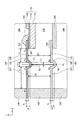
図8は、第1のセパレータ120および第2のセパレータ180の詳細構成を示す説明図である。図8には、図4のPx部の構成が拡大して示されている。ここで、図4に示された発電単位102の断面は、Z軸方向視における単セル110の中心点POを通り、かつ、Z軸方向に平行な断面である。なお、本実施形態の発電単位102では、Z軸方向視における単セル110の中心点POを通り、かつ、Z軸方向に平行な任意の断面において、以下に示す第1のセパレータ120および第2のセパレータ180の構成が採用されている。
A-3. Detailed configuration of the
FIG. 8 is an explanatory diagram showing a detailed configuration of the
A−3−1.第1のセパレータ120の詳細構成:
第1のセパレータ120について説明する。図8に示すように、第1のセパレータ120は、第1の内側部126と、第1の外側部127と、第1の連結部128とを備える。第1の内側部126は、第1の貫通孔周囲部122を含んでいる。第1の外側部127は、第1の内側部126より外周側に位置している。第1の連結部128は、第1の内側部126の端部と第1の外側部127の端部とを連結するよう配置されている。
A-3-1. Detailed configuration of the first separator 120:
The
第1の内側部126と第1の外側部127とのZ軸方向における位置は、互いに略同一である。ここで、第1の内側部126と第1の外側部127とのZ軸方向における位置が、互いに略同一とは、Z軸方向において、第1の内側部126の位置が、第1の外側部127の位置の±5mmの範囲内であることを意味する。なお、第1の内側部126のZ軸方向における位置とは、第1の内側部126の表面の内の空気室166に面している側(上側)の表面において、第1の内側部126における最も上に位置する部分の位置を意味する。第1の外側部127のZ軸方向における位置とは、第1の外側部127の表面の内の空気室166に面している側(上側)の表面において、第1の外側部127における最も上に位置する部分の位置を意味する。
The positions of the first
図8において、第1の内側部126の第1の長さL1は、第1の外側部127の第2の長さL2より短い。ここで、第1の長さL1は、第1の内側部126と第1の連結部128との境界点P2と、Z軸方向視での第1の内側部126における単セル110(電解質層112)の外縁と重なる点P1との、X軸方向における長さである。第2の長さL2は、第1の外側部127と第1の連結部128との境界点P4と、Z軸方向視での第1の外側部127における空気極側フレーム部材130の内縁と重なる点P3との、X軸方向における長さである。すなわち、第1の長さL1が第2の長さL2より短いとは、換言すれば、Z軸方向視において第1の連結部128は、単セル110(電解質層112)の外縁と空気極側フレーム部材130の内縁との間において、単セル110(電解質層112)の外縁よりも、空気極側フレーム部材130の内縁から遠い位置にあることを意味する。なお、第1の内側部126の第1の長さL1は、第1の外側部127の第2の長さL2に比べて、好ましくは、1mm〜5mm短い。
In FIG. 8, the first length L 1 of the first
第1のセパレータ120の配列方向における厚さ(板厚)t1は、0.01(mm)以上であればよく、耐酸化性の低下を抑制する観点から、好ましくは0.03(mm)以上、より好ましくは0.05(mm)以上であって、0.2(mm)以下であることが好ましい。第1のセパレータ120の厚さt1を0.03(mm)以上とすることにより、第1のセパレータ120の耐酸化性の低下を抑制することができ、第1のセパレータ120の厚さt1を0.2(mm)以下とすることにより、第1の連結部128のバネ性を一定程度以上確保することができる。このため、熱サイクルやヒートショック等によって単セル110を面方向に変形させる荷重がかかった場合に、第1のセパレータ120の第1の連結部128の存在により、第1のガラスシール部125や単セル110に発生する応力が緩和される。これにより、第1のガラスシール部125や単セル110の変形や割れを抑制することができる。
The thickness (plate thickness) t 1 of the
第1の連結部深さH1は、0.1(mm)以上、0.6(mm)以下であることがさらに好ましい。第1の連結部深さH1を0.1(mm)以上とすることにより、第1の連結部128による第1のガラスシール部125や単セル110の変形や割れを抑制する効果を確保することができる。また、第1の連結部深さH1が0.6(mm)より高くなると、第1の連結部128によってガスの流れが阻害され、発電性能が低下するおそれがあるため好ましくないが、第1の連結部深さH1を0.6(mm)以下とすることにより、第1の連結部128によってガスの流れが阻害されて発電性能が低下することを抑制することができる。
The depth H1 of the first connecting portion is more preferably 0.1 (mm) or more and 0.6 (mm) or less. By setting the depth H 1 of the first connecting portion to 0.1 (mm) or more, the effect of suppressing deformation and cracking of the first
また、第1の連結部深さH1は第1のセパレータ120の厚さt1より大きいことが好ましい。第1の連結部深さH1を第1のセパレータ120の厚さt1より大きくすることにより、第1の連結部128による第1のガラスシール部125や単セル110の変形や割れを抑制する効果を確保することができる。
Further, it is preferable that the depth H 1 of the first connecting portion is larger than the thickness t 1 of the
本実施形態では、第1の連結部128は、Y軸方向視において、第1の内側部126および第1の外側部127の位置から燃料室176側(下側)に突出するように湾曲した形状を有している。すなわち、第1の連結部128における燃料室176側(下側)は凸部となり、第1の連結部128における空気室166側(上側)は凹部となる。このように、第1の連結部128は、上下方向における位置が第1の内側部126および第1の外側部127とは異なる部分を含む。なお、第1の連結部128は、上下方向視で、第1の貫通孔121を取り囲むように形成されている(図6参照)。また、第1のセパレータ120における第1の連結部128は、例えば、プレス加工により形成される。第1のセパレータ120の第1の連結部128は、上述した構成であるため、面方向に容易に伸び縮みするバネのように機能する。そのため、本実施形態の第1のセパレータ120は、第1の連結部128を備えない構成と比較して、第1の連結部128の位置で面方向に変形しやすい。
In the present embodiment, the first connecting
上述したように、第1の貫通孔周囲部122における下方向側の表面は、ロウ材を含む第1の接合部124を介して、単セル110(電解質層112)の周縁部における上方向側の表面に接合されている。すなわち、第1の内側部126の第1の貫通孔周囲部122は、Z軸方向での第1の内側部126の下方向側、つまり、第1の連結部128が突出している方向と同方向の側において、第1の接合部124を介して電解質層112と接合されている。
As described above, the lower surface of the first through hole
A−3−2.第2のセパレータ180の詳細構成:
次に、第2のセパレータ180について説明する。図8に示すように、第2のセパレータ180は、第2の内側部186と、第2の外側部187と、第2の連結部188とを備える。第2の内側部186は、第2の貫通孔周囲部182を含んでいる。第2の外側部187は、第2の内側部186より外周側に位置している。第2の連結部188は、第2の内側部186の端部と第2の外側部187の端部とを連結するよう配置されている。
A-3-2. Detailed configuration of the second separator 180:
Next, the
第2の内側部186と第2の外側部187との上下方向における位置は、互いに略同一である。ここで、第2の内側部186と第2の外側部187とのZ軸方向における位置が、互いに略同一とは、Z軸方向において、第2の内側部186の位置が、第2の外側部187の位置の±5mmの範囲内であることを意味する。なお、第2の内側部186のZ軸方向における位置とは、第2の内側部186の表面の内の燃料室176に面している側(上側)の表面において、第2の内側部186における最も上に位置する部分の位置を意味する。第2の外側部187のZ軸方向における位置とは、第2の外側部187の表面の内の燃料室176に面している側(上側)の表面において、第2の外側部187における最も上に位置する部分の位置を意味する。
The positions of the second
第2のセパレータ180の配列方向における厚さ(板厚)t2は、第1のセパレータ120の配列方向における厚さ(板厚)t1と同様、0.01(mm)以上であればよく、耐酸化性の低下を抑制する観点から、好ましくは0.03(mm)以上、より好ましくは0.05(mm)以上であって、0.2(mm)以下であることが好ましい。第2のセパレータ180の厚さt2を0.03(mm)以上とすることにより、第2のセパレータ180の耐酸化性の低下を抑制することができ、第2のセパレータ180の厚さt2を0.2(mm)以下とすることにより、第2の連結部188のバネ性を一定程度以上確保することができる。このため、熱サイクルやヒートショック等によってインターコネクタ150を面方向に変形させる荷重がかかった場合に、第2のセパレータ180の第2の連結部188の存在により、インターコネクタ150への応力が緩和され、ひいては、当該応力が単セル110へかかることを抑制することができる。これにより、単セル110の変形や割れを抑制することができる。
The thickness (plate thickness) t 2 of the
第2の連結部深さH2は、第1のセパレータ120の第1の連結部深さH1と同様、0.1(mm)以上、0.6(mm)以下であることがさらに好ましい。第2の連結部深さH2を0.1(mm)以上とすることにより、第2の連結部188による単セル110の変形や割れを抑制する効果を確保することができる。また、第2の連結部深さH2が0.6(mm)より高くなると、第2の連結部188によってガスの流れが阻害され、発電性能が低下するおそれがあるため好ましくないが、第2の連結部深さH2を0.6(mm)以下とすることにより、第2の連結部188によってガスの流れが阻害されて発電性能が低下することを抑制することができる。
The second connecting portion depth H 2 is more preferably 0.1 (mm) or more and 0.6 (mm) or less, similarly to the first connecting portion depth H 1 of the first separator 120. .. By setting the depth H 2 of the second connecting portion to 0.1 (mm) or more, the effect of suppressing deformation or cracking of the
また、第2の連結部深さH2は第2のセパレータ180の厚さt2より大きいことが好ましい。第2の連結部深さH2を第2のセパレータ180の厚さt2より大きくすることにより、第2の連結部188による単セル110の変形や割れを抑制する効果を確保することができる。
Further, it is preferable that the depth H 2 of the second connecting portion is larger than the thickness t 2 of the
本実施形態では、第2の連結部188は、第1の連結部128から離間するように配置されている。また、第2の連結部188は、第2の内側部186および第2の外側部187の位置から空気室166側(下側)に突出するように湾曲した形状を有している。すなわち、第2の連結部188における空気室166側(下側)は凸部となり、第2の連結部188における燃料室176側(上側)は凹部となる。このように、第2の連結部188は、上下方向における位置が第2の内側部186および第2の外側部187とは異なる部分を含む。第2の連結部188は、上述の構成であるため、第1の連結部128と同じ側(下側)に突出していることとなる。なお、第2の連結部188は、上下方向視で、第2の貫通孔181を取り囲むように形成されている(図7参照)。また、第2のセパレータ180における第2の連結部188は、例えば、プレス加工により形成される。第2のセパレータ180の第2の連結部188は、上述した構成であるため、面方向に容易に伸び縮みするバネのように機能する。そのため、本実施形態の第2のセパレータ180は、第2の連結部188を備えない構成と比較して、第2の連結部188の位置で面方向に変形しやすい。
In the present embodiment, the second connecting
上述したように、第2の貫通孔周囲部182における下方向側の表面は、溶接により、インターコネクタ150の周縁部における上方向側の表面に接合されている。すなわち、第2の内側部186の第2の貫通孔周囲部182は、Z軸方向での第2の内側部186の下方向側、つまり、第2の連結部188が突出している方向と同方向の側において、インターコネクタ150と接合されている。
As described above, the lower surface of the second through hole
A−3−3.第1のセパレータ120と第2のセパレータ180との位置関係:
図8を用いて、第1のセパレータ120と第2のセパレータ180との位置関係について説明する。本実施形態において、Z軸方向視において、第1の最突出部P5は、第2の最突出部Q5と略同一の位置に位置している。すなわち、第1の最突出部P5と、第2の最突出部Q5とは、いずれも仮想直線VL上に位置している。
A-3-3. Positional relationship between the
The positional relationship between the
ここで、Z軸方向視において、第1の最突出部P5が第2の最突出部Q5と略同一の位置に位置しているとは、Z軸方向視での第1の最突出部P5と第2の最突出部Q5との間の距離が、0mm〜15mmの範囲内であることを意味する。また、第1の最突出部P5は、第1の連結部128の内、Z軸方向において最も下方向側に突出している部分である。第2の最突出部Q5は、第2の連結部188の内、Z軸方向において最も下方向側に突出している部分である。仮想直線VLは、第1の最突出部P5と第2の最突出部Q5とを通る直線である。
Here, the fact that the first most protruding portion P 5 is located at substantially the same position as the second most protruding portion Q 5 in the Z-axis direction is the first most protruding portion in the Z-axis direction. This means that the distance between the portion P 5 and the second most protruding portion Q 5 is within the range of 0 mm to 15 mm. Further, the first most protruding portion P 5 is a portion of the first connecting
なお、上述したように、第1のセパレータ120の第1の連結部128は、Z軸方向視において、単セル110(電解質層112)の外縁と空気極側フレーム部材130の内縁との間において、単セル110(電解質層112)の外縁よりも、空気極側フレーム部材130の内縁に近い位置にある。このため、第2のセパレータ180の第2の連結部188についても、第1の連結部128と同様に、Z軸方向視において、単セル110(電解質層112)の外縁と空気極側フレーム部材130(燃料極側フレーム部材140)の内縁との間において、単セル110(電解質層112)の外縁よりも、空気極側フレーム部材130(燃料極側フレーム部材140)の内縁に近い位置にある。
As described above, the first connecting
本実施形態において、内側部間距離D1と、外側部間距離D2と、連結部間距離D3とは、互いに略同一である。ここで、内側部間距離D1と、外側部間距離D2と、連結部間距離D3とが、互いに略同一とは、内側部間距離D1および外側部間距離D2が、それぞれ、連結部間距離D3を基準として、±5mmの範囲内であることを意味する。 In the present embodiment, the distance between the inner portions D 1 , the distance D 2 between the outer portions, and the distance D 3 between the connecting portions are substantially the same as each other. Here, the distance D 1 between the inner portions, the distance D 2 between the outer portions, and the distance D 3 between the connecting portions are substantially the same as each other, that is, the distance D 1 between the inner portions and the distance D 2 between the outer portions are substantially the same. with reference to the connection portion distance D 3, which means that it is within a range of ± 5 mm.
上記において、内側部間距離D1は、Z軸方向における第1の内側部126と第2の内側部186との間の距離である。より詳しくは、内側部間距離D1は、第1の内側部126の表面の内の燃料室176に面している側(下側)の表面において、第1の内側部126における最も下に位置する部分から、第2の内側部186の表面の内の燃料室176に面している側(上側)の表面において、第2の内側部186における最も上に位置する部分までの距離である。外側部間距離D2は、Z軸方向における第1の外側部127と第2の外側部187との間の距離である。より詳しくは、外側部間距離D2は、第1の外側部127の表面の内の燃料室176に面している側(下側)の表面において、第1の外側部127における最も下に位置する部分から、第2の外側部187の表面の内の燃料室176に面している側(上側)の表面において、第2の外側部187における最も上に位置する部分までの距離である。連結部間距離D3は、Z軸方向における第1の連結部128と第2の連結部188との間の距離である。より詳しくは、連結部間距離D3は、第1の連結部128の表面の内の燃料室176に面している側(下側)の表面における第1の最突出部P5から、第2の連結部188の表面の内の燃料室176に面している側(上側)の表面において、第2の最突出部Q5と重なる部分までの距離である。
In the above, the distance D 1 between the inner portions is the distance between the first
第1の連結部幅L3は、第2の連結部幅L4と略同一である。ここで、第1の連結部幅L3が第2の連結部幅L4と略同一であるとは、第1の連結部幅L3と第2の連結部幅L4との差が、0mm〜10mmの範囲内であることを意味する。なお、第1の連結部幅L3は、X軸方向における境界点P2と境界点P4との間の距離である。第2の連結部幅L4は、X軸方向における境界点Q2と境界点Q4との間の距離である。なお、第1の連結部幅L3は、第1のセパレータ120の第1の内側部126における第1の長さL1と、第1の外側部127における第2の長さL2と、第1の連結部幅L3とを足した合計長さの1/2以下であり、好ましくは、1/3以下である。第1の長さL1と、第2の長さL2と、第1の連結部幅L3とを足した合計長さは、Z軸方向視での第1の内側部126における単セル110(電解質層112)の外縁と重なる点から、Z軸方向視での第1の外側部127における空気極側フレーム部材130の内縁と重なる点までの長さと同等である。また、第2の連結部幅L4についても、Z軸方向視での第2の内側部186におけるインターコネクタ150の外縁と重なる点から、Z軸方向視での第2の外側部187における燃料極側フレーム部材140の内縁と重なる点までの長さの1/2以下であり、好ましくは、1/3以下である。
The first connecting portion width L 3 is substantially the same as the second connecting portion width L 4. Here, the first connecting portion width L 3 is a second stand for the same as the connecting portion width L 4 of the difference between the first connecting portion width L 3 and the second connecting portion width L 4 of It means that it is within the range of 0 mm to 10 mm. The first connecting portion width L 3 is the distance between the boundary point P 2 and the boundary point P 4 in the X-axis direction. The second connecting portion width L 4 is the distance between the boundary point Q 2 and the boundary point Q 4 in the X-axis direction. The width L 3 of the first connecting portion includes a first length L 1 in the first
第1の連結部深さH1は、第2の連結部深さH2と略同一である。ここで、第1の連結部深さH1が第2の連結部深さH2と略同一であるとは、第1の連結部深さH1と第2の連結部深さH2との差が、0mm〜10mmの範囲内であることを意味する。なお、第1の連結部深さH1は、第1の連結部128のZ軸方向における深さである。より詳細には、第1の連結部深さH1は、第1の連結部128の空気室166に面している側(上側)の表面において、第1の連結部128における最も上に位置する部分から最も下に位置する部分までの距離(深さ)である。第2の連結部深さH2は、第2の連結部188のZ軸方向における深さである。より詳細には、第2の連結部深さH2は、第2の連結部188の燃料室176に面している側(上側)側の表面において、第2の連結部188における最も上に位置する部分から最も下に位置する部分までの距離(深さ)である。
The first connecting portion depth H 1 is substantially the same as the second connecting portion depth H 2. Here, the fact that the first connecting portion depth H 1 is substantially the same as the second connecting portion depth H 2 means that the first connecting portion depth H 1 and the second connecting portion depth H 2 Means that the difference is within the range of 0 mm to 10 mm. The depth H1 of the first connecting portion is the depth of the first connecting
なお、第1のセパレータ120と第2のセパレータ180との間、すなわち、第1の内側部126と第2の内側部186との間、第1の外側部127と第2の外側部187との間、および、第1の連結部128と第2の連結部188との間は、空気室166または燃料室176の一部であるとともに、空気極114または燃料極116へ酸化剤ガスOGまたは燃料ガスFGを供給するガス流路として機能する。
Between the
A−3−4.第1のセパレータ120および第2のセパレータ180の各部分の特定:
第1のセパレータ120における第1の内側部126と、第1の外側部127と、第1の連結部128とは、次のように特定することができる。まず、Z軸方向視で単セル110の中心POを通り、かつ、Z軸方向に平行な少なくとも1つの第1のセパレータ120の断面において、第1のセパレータ120におけるZ軸方向の下方向側の表面上の点であって、Z軸方向における単セル110からの距離が最も大きい点(図8において、第1の最突出部P5)を特定する。この第1の最突出部P5における接線と、第1の最突出部P5を通り、かつ、Z軸に平行な仮想直線とのなす角θを特定する。次に、第1の最突出部P5から面方向における単セル110側へ所定間隔でZ軸に平行な仮想直線を引く。第1のセパレータ120と仮想直線との交点(点Pn)における接線と、当該点Pnにおける仮想直線とのなす角θn(ただし、0°≦θn≦90°)を特定する。当該なす角θnを順に特定し、当該なす角θnがθn−1<θnになった点Pn(例えば、θn−1=18°、θn=20°)を、第1の連結部128と第1の内側部126との境界点BPnとする。一方、同様に、第1の最突出部P5から面方向における燃料極側フレーム部材140側へ所定間隔でZ軸に平行な仮想直線を引く。第1のセパレータ120と仮想直線との交点(点Pm)における接線と、当該点Pmにおける仮想直線とのなす角θm(ただし、0°≦θm≦90°)を特定する。当該なす角θmを順に特定し、なす角θmがθm−1<θmになった点Pmを、第1の連結部128と第1の外側部127との境界点BPmとする。第1のセパレータ120において、境界点BPmと境界点BPnとの間に位置する部分を第1の連結部128と特定することができる。また、第1のセパレータ120において、境界点BPnから単セル110側の部分を第1の内側部126と特定し、境界点BPmから燃料極側フレーム部材140側の部分を第1の外側部127と特定することができる。後述の第2のセパレータ180における第2の内側部186と、第2の外側部187と、第2の連結部188とについても、上記第1のセパレータ120における各部分を特定する方法と同様にして特定することができる。
A-3-4. Identification of each part of the
The first
A−4.本実施形態の効果:
以上説明したように、本実施形態の燃料電池スタック100を構成する各発電単位102は、単セル110と、インターコネクタ150と、第1のセパレータ120と、第2のセパレータ180とを備える。単セル110は、電解質層112と、電解質層112を挟んでZ軸方向に互いに対向する空気極114および燃料極116とを含む。インターコネクタ150は、単セル110のZ軸方向に配置されている。
A-4. Effect of this embodiment:
As described above, each
第1のセパレータ120には、Z軸方向に貫通する第1の貫通孔121が形成されている。第1のセパレータ120における第1の貫通孔121を取り囲む部分である第1の貫通孔周囲部122は、単セル110の周縁部と接合されている。第1のセパレータ120により、空気極114に面する空気室166と、燃料極116に面する燃料室176とが区画される。第1のセパレータ120は、第1の内側部126と、第1の外側部127と、第1の連結部128とを有している。第1の内側部126は、第1の貫通孔周囲部122を含んでいる。第1の外側部127は、第1の内側部126より外周側に位置している。第1の連結部128は、第1の内側部126と第1の外側部127とを連結すると共に第1の内側部126と第1の外側部127との両方に対して、上下方向の下方向側に突出している。
The
第2のセパレータ180には、Z軸方向に貫通する第2の貫通孔181が形成されている。第2のセパレータ180における第2の貫通孔181を取り囲む部分である第2の貫通孔周囲部182は、インターコネクタ150の周縁部と接合されている。第2のセパレータ180により、燃料室176と、隣接する他の単セル110の空気極114に面する空気室166とが区画される。第2のセパレータ180は、第2の内側部186と、第2の外側部187と、第2の連結部188とを有している。第2の内側部186は、第2の貫通孔周囲部182を含んでいる。第2の外側部187は、第2の内側部186より外周側に位置している。第2の連結部188は、第2の内側部186と第2の外側部187とを連結する共に、第2の内側部186と第2の外側部187との両方に対して、上下方向の下方向側に突出している。第2の連結部188は、さらに、第1の連結部128から離間している。
The
このように、本実施形態の発電単位102は、Z軸方向において、第1のセパレータ120の第1の連結部128が第1の内側部126と第1の外側部127との両方に対して、Z軸方向の下方向側に突出しているため、第1のセパレータ120の第1の連結部128がZ軸方向に直交する面方向に容易に伸び縮みするバネのように機能し、第1のセパレータ120が第1の連結部128の位置で面方向に変形することを可能にする。このため、熱サイクルやヒートショック等によって単セル110を面方向に変形させる荷重がかかった場合に、第1のセパレータ120が応力を緩和する機能(応力緩和機能)を発揮することができる。すなわち、単セル110に接合している第1のセパレータ120は主として第1の連結部128がZ軸方向に撓むことにより第1の連結部128の位置で面方向に変形し、単セル110にかかる応力を緩和することができる。これにより、単セル110の変形や割れを抑制することができる。
As described above, in the
本実施形態の発電単位102は、Z軸方向において、第2のセパレータ180の第2の連結部188が第2の内側部186と第2の外側部187との両方に対して、Z軸方向の下方向側に突出しているため、第1のセパレータ120と同様に、第2のセパレータ180が第2の連結部188の位置で面方向に変形することを可能とする。このため、熱サイクルやヒートショック等によってインターコネクタ150を面方向に変形させる荷重がかかった場合に、第2のセパレータ180が応力緩和機能を発揮することができる。このように、インターコネクタ150への応力が緩和されることにより、インターコネクタ150と単セル110との間に介在する空気極側集電体134を介して、当該応力が単セル110へかかることを抑制することができる。これにより、単セル110の変形や割れを抑制することができる。
In the
本実施形態の発電単位102では、さらに、Z軸方向において、第1のセパレータ120の第1の連結部128と、第2のセパレータ180の第2の連結部188とが、互いに同じ方向(具体的には、下方向)に突出している。このため、第1のセパレータ120および第2のセパレータ180が共に応力緩和機能を発揮する際、すなわち、第1の連結部128および第2の連結部188の両方が下方向に撓む際であっても、空気室166および燃料室176のいずれのガス室においても、第1の連結部128および第2の連結部188の両方によりガス流路が狭窄されることを抑制することができる。これにより、空気室166および燃料室176における安定的かつ良好な酸化剤ガスOGおよび燃料ガスFGの流入が阻害されることを抑制し、ひいては、空気室166および燃料室176が面している単セル110面における反応効率の低下を抑制することができる。また、ガス流路の狭窄が抑制されることにより、発電単位102の圧力損失が増大することを抑制し、この結果、発電単位102の性能低下を抑制することができる。発電単位102における圧力損失の増大が抑制された場合、例えば、酸化剤ガスOGおよび燃料ガスFGを空気室166および燃料室176に導入するために用いられるブロワ等の補機に要する電力の増大を抑制することができる。従って、本実施形態の発電単位102では、単セル110の変形や割れを抑制しつつ、単セル110面における反応効率の低下を抑制し、かつ、発電単位102の圧力損失が増大することを抑制し、ひいては、発電単位102の性能を向上させることができる。
In the
本実施形態の発電単位102では、Z軸方向視において、第1の連結部128が、第2の連結部188と重なっている。このような構成とすることにより、第1の連結部128および第2の連結部188がZ軸方向に撓んだ場合であっても、第1のセパレータ120の第1の連結部128と第2のセパレータ180との離間距離および第2のセパレータ180の第2の連結部188と第2のセパレータ180との離間距離を確保し易い構造を実現できる。このため、ガス流路の確保が容易となり、ひいては、単セル110面における反応効率の低下を効果的に抑制することができる。また、ガス流路の確保が容易となることにより、発電単位102の圧力損失が増大することを効果的に抑制することができる。更には、第1の連結部128および第2の連結部188のZ軸方向への突出深さを深くすることが可能となり、ひいては、応力緩和機能を効果的に発揮させることができうる。従って、本実施形態の発電単位102では、単セル110の変形や割れを効果的に抑制しつつ、単セル110面における反応効率の低下を効果的に抑制し、かつ、発電単位102の圧力損失が増大することを効果的に抑制し、ひいては、発電単位102の性能を効果的に向上させることができる。
In the
本実施形態の発電単位102では、第1の内側部126と第2の内側部186との間のZ軸方向における内側部間距離D1と、第1の外側部127と第2の外側部187との間のZ軸方向における外側部間距離D2と、第1の連結部128の第1の最突出部P5と第2の連結部188の第2の最突出部Q5との間のZ軸方向における連結部間距離D3とは、互いに略同一である。このような構成とすることにより、空気室166および燃料室176の両方において、酸化剤ガスOGまたは燃料ガスFGの流れ方向における各断面である、第1の内側部126と第2の内側部186との間に形成されるガス流路断面と、第1の外側部127と第2の外側部187との間に形成されるガス流路断面と、第1の連結部128と第2の連結部188との間に形成されるガス流路断面とにおける各断面積が互いに略同一となる構成を実現できる。このため、空気室166および燃料室176におけるガス流れの安定性を向上させることができ、単セル110面における反応効率の低下を更に効果的に抑制することができる。従って、本実施形態の発電単位102では、単セル110面における反応効率の低下を更に効果的に抑制し、ひいては、発電単位102の性能を更に効果的に向上させることができる。
In the power generation unit 102 of the present embodiment, the distance D 1 between the inner portions in the Z-axis direction between the first
本実施形態の発電単位102では、第1の内側部126と第1の外側部127とのZ軸方向における位置は互いに略同一であり、かつ、第2の内側部186と第2の外側部187とのZ軸方向における位置は互いに略同一である。このような構成とすることにより、酸化剤ガスOGおよび燃料ガスFGのガス流れの方向が、面方向と略平行となる構成を実現できる。このため、空気室166および燃料室176におけるガス流れの安定性を更に向上させることができ、単セル110面における反応効率の低下を更に効果的に抑制することができる。従って、本実施形態の発電単位102では、単セル110面における反応効率の低下を更に効果的に抑制し、ひいては、発電単位102の性能を更に効果的に向上させることができる。
In the
本実施形態の発電単位102では、Z軸方向に貫通する空気室用孔131であって、空気室166を構成する空気室用孔131が形成された空気極側フレーム部材130を備える。また、Z軸方向視での単セル110の中心点POを通り、かつ、Z軸方向に平行な少なくとも1つの断面において、第1の内側部126における、第1の内側部126と第1の連結部128との境界点P2と単セル110の外縁との間の面方向における第1の長さL1は、第1の外側部127における、第1の外側部127と第1の連結部128との境界点P4と空気極側フレーム部材130の内縁との間の面方向における第2の長さL2より短い。熱サイクルやヒートショック等により、第1のセパレータ120に応力がかかる際、その応力は第1のセパレータ120の第1の連結部128に集中する傾向がある。そして、単セル110の外縁から第1の連結部128までの第1の長さL1が短いほど、単セル110は第1の連結部128にかかる応力の影響を受けやすく、単セル110の変形や割れを生じやすい。本発電単位102では、上述のとおりの構成とすることにより、第1の連結部128は、第1のセパレータ120において単セル110からより離れた外周側に位置する構成を実現できる。これにより、第1の連結部128にかかる応力が、単セル110にかかりにくい構成を実現できる。従って、本実施形態の発電単位102では、単セル110の変形や割れを更に効果的に抑制し、ひいては、発電単位102の性能を更に効果的に向上させることができる。
The
本実施形態の発電単位102では、第1の貫通孔周囲部122におけるZ軸方向の下方向側の表面は、ロウ材を含む第1の接合部124を介して、単セル110の周縁部におけるZ軸方向の上方向側の表面に接合されている。上述したように、第1のセパレータ120に応力がかかり、第1のセパレータ120が第1の連結部128の位置で面方向に変形する際、第1の連結部128には下方向の応力がかかる。このように、本実施形態の発電単位102では、第1の連結部128にかかる応力の方向(下方向)と第1のセパレータ120の単セル110からの剥離方向(上方向)とが略反対方向となる構成を採用している。このため、Z軸方向において下方側に突出している第1の連結部128にZ軸方向において下方側への応力がかかった際に、第1のセパレータ120が単セル110から剥離しにくい。従って、本実施形態の発電単位102では、発電単位102の性能を向上させることができると共に、第1のセパレータ120の単セル110からの剥離を抑制することができる。
In the
B.変形例:
本明細書で開示される技術は、上述の実施形態に限られるものではなく、その要旨を逸脱しない範囲において種々の形態に変形することができ、例えば次のような変形も可能である。
B. Modification example:
The technique disclosed in the present specification is not limited to the above-described embodiment, and can be transformed into various forms without departing from the gist thereof. For example, the following modifications are also possible.
上記実施形態において、Z軸方向視における、第1のセパレータ120の第1の連結部128と第2のセパレータ180の第2の連結部188との位置関係は、図9(A)に示す位置関係であってもよい。具体的には、Z軸方向視において、第2の連結部188の第2の連結部幅L4の範囲内に、第1の連結部128の第1の最突出部P5が位置する位置関係とすることができる。
In the above embodiment, the positional relationship between the first connecting
上記実施形態において、Z軸方向視における、第1の連結部128と第2の連結部188との位置関係は、図9(B)に示す位置関係であってもよい。具体的には、Z軸方向視において、第1の連結部128の第1の連結部幅L3に対して、第2の連結部188の第2の連結部幅L4の一部が重なっている位置関係とすることができる。換言すれば、第1の連結部128の少なくとも一部分が第2の連結部188の少なくとも一部分に重なっている位置関係である。なお、図9(B)では、第2の連結部188の内の第2の外側部187側において、第2の連結部幅L4の一部が第1の連結部幅L3に重なっている構成を示したが、これに限らず、第2の連結部188の内の第2の内側部186側において、第2の連結部幅L4の一部が第1の連結部幅L3に重なっている構成としてもよい。
In the above embodiment, the positional relationship between the first connecting
上記実施形態において、Z軸方向視における、第1の連結部128と第2の連結部188との位置関係は、図10(A)に示す位置関係であってもよい。具体的には、Z軸方向において、第1の連結部幅L3に対して、第2の連結部幅L4が重なっていない位置関係とすることができる。換言すれば、第1の連結部128の少なくとも一部分が第2の連結部188の少なくとも一部分に重なっていない位置関係である。なお、図10(A)では、第2の連結部188は、第1の連結部128に対して、第1の内側部126側に位置する構成を示したが、これに限らず、第2の連結部188が第1の外側部127側に位置する構成としてもよい。
In the above embodiment, the positional relationship between the first connecting
上記実施形態において、図10(B)に示すように、第1の連結部128および第2の連結部188が、いずれも上下方向において上側に突出している構成であってもよい。具体的には、第1の連結部128が、第1の内側部126および第1の外側部127の位置から空気室166側(上側)に突出するように湾曲した形状を有していてもよい。すなわち、第1の連結部128における空気室166側(上側)は凸部となり、第1の連結部128における燃料室176側(下側)は凹部となる構成である。また、第2の連結部188についても第1の連結部128と同様に、第2の連結部188が、第2の内側部186および第2の外側部187の位置から燃料室176側(上側)に突出するように湾曲した形状を有していてもよい。すなわち、第2の連結部188における燃料室176側(上側)は凸部となり、第2の連結部188における空気室166側(下側)は凹部となる構成である。
In the above embodiment, as shown in FIG. 10B, both the first connecting
上記実施形態において、第1のセパレータ120は、第1の貫通孔周囲部122の表面の内の上方向側の表面において、単セル110を構成する燃料極116における電解質層112に対向する側(下側)の表面の周縁部に対向している構成としてもよい。この場合においても、第1のセパレータ120は、第1の貫通孔周囲部122に配置されたロウ材を含む第1の接合部124により、単セル110(燃料極116)と接合されうる。また、第2のセパレータ180は、第2の貫通孔周囲部182の表面の内の上方向側の表面において、インターコネクタ150における空気極114に対向する側(下側)の表面の周縁部に対向している構成としてもよい。この場合においても、第2のセパレータ180は、第2の貫通孔周囲部182において、例えば溶接により、インターコネクタ150と接合されうる。
In the above embodiment, the
上記実施形態において、第1のセパレータ120および第2のセパレータ180は、Z軸方向視における単セル110の中心点POを通り、かつ、Z軸方向に平行な一部の断面において、上述の構成となっていてもよい。例えば、Z軸方向視において、第1の貫通孔121を取り囲むように形成される第1の連結部128は、第1の貫通孔121を取り囲む周の内の一部において形成されていなくてもよい。
In the above embodiment, the
上記実施形態において、第1の連結部128および第2の連結部188は、Y軸方向視において、湾曲した形状に限らず、矩形状等、応力緩和機能を発揮可能な形状を採用してもよい。
In the above embodiment, the first connecting
上記実施形態において、第1の連結部128の表面の内の燃料室176に面している側(下側)の表面から第2の連結部188の表面の内の燃料室176に面している側(上側)の表面までの、Z軸方向における距離はいずれの部分においても同一であってもよく、また、一部分において異なっていてもよい。
In the above embodiment, the surface of the first connecting
上記実施形態において、第1の連結部128の第1の連結部幅L3は、第2の連結部188の第2の連結部幅L4と異なっていてもよい。
In the above embodiment, the first connecting portion width L 3 of the first connecting
上記実施形態において、内側部間距離D1と、外側部間距離D2と、連結部間距離D3とを、燃料室176における距離としたが、空気室166における距離としてもよい。この場合、上記において、第1の内側部126を第2の内側部186と、第1の外側部127を第2の外側部187と、第1の連結部128を第2の連結部188と、空気室166を燃料室176と読み替えることとする。
In the above embodiment, the distance D 1 between the inner portions, the distance D 2 between the outer portions, and the distance D 3 between the connecting portions are defined as the distances in the
上記実施形態において、第1のセパレータ120と第2のセパレータ180との間の距離である、内側部間距離D1と、外側部間距離D2と、連結部間距離D3との内の少なくとも1つの距離は他の距離と異なっていてもよい。
In the above embodiment, the
上記実施形態において、Z軸方向における、第1の内側部126の位置と第1の外側部127の位置とは異なっていてもよい。また、Z軸方向における、第2の内側部186の位置と第2の外側部187の位置とは異なっていてもよい。
In the above embodiment, the position of the first
上記実施形態において、第1の内側部126における第1の長さL1は、第1の外側部127における第2の長さL2と同等であってもよく、また、短くてもよい。
In the above embodiment, the first length L 1 in the first
上記実施形態において、第1のセパレータ120により、空気極114に面する空気室166と燃料極116に面する燃料室176とが区画され、かつ、第2のセパレータ180により、空気室166と、隣接する他の単セル110の燃料極116に面する燃料室176とが区画されることとしてもよい。この場合、上述において、第1の電極を燃料極116と読み替え、第2の電極を空気極114と読み替え、第1のガス室を燃料室176と読み替え、第2のガス室を空気室166と読み替えるものとする。
In the above embodiment, the
上記実施形態では、空気室166における酸化剤ガスOGの主たる流れ方向と燃料室176における燃料ガスFGの主たる流れ方向とが交差するクロスフロータイプを例に挙げて説明しているが、本発明は、他のタイプ(上記2つの流れ方向が略同一方向であるコフロータイプや上記2つの流れ方向が略反対方向であるカウンターフロータイプ等)にも適用可能である。
In the above embodiment, a cross-flow type in which the main flow direction of the oxidant gas OG in the
上記実施形態において、燃料電池スタック100に含まれる発電単位102の個数は、あくまで一例であり、発電単位102の個数は燃料電池スタック100に要求される出力電圧等に応じて適宜決められる。また、上記実施形態において、空気極114と電解質層112との間に中間層が配置されていてもよい。また、上記実施形態における各部材を構成する材料は、あくまで例示であり、各部材が他の材料により構成されていてもよい。
In the above embodiment, the number of
上記実施形態では、燃料ガスに含まれる水素と酸化剤ガスに含まれる酸素との電気化学反応を利用して発電を行うSOFCを対象としているが、本発明は、水の電気分解反応を利用して水素の生成を行う固体酸化物形電解セル(SOEC)の構成単位である電解セル単位や、複数の電解セル単位を備える電解セルスタックにも同様に適用可能である。なお、電解セルスタックの構成は、例えば特開2016−81813号に記載されているように公知であるためここでは詳述しないが、概略的には上述した実施形態における燃料電池スタック100と同様の構成である。すなわち、上述した実施形態における燃料電池スタック100を電解セルスタックと読み替え、発電単位102を電解セル単位と読み替え、単セル110を電解単セルと読み替えればよい。ただし、電解セルスタックの運転の際には、空気極114がプラス(陽極)で燃料極116がマイナス(陰極)となるように両電極間に電圧が印加されると共に、連通孔108を介して原料ガスとしての水蒸気が供給される。これにより、各電解セル単位において水の電気分解反応が起こり、燃料室176で水素ガスが発生し、連通孔108を介して電解セルスタックの外部に水素が取り出される。このような構成の電解セル単位および電解セルスタックにおいても、上記実施形態と同様の構成を採用すると、単セル110の変形や割れを抑制し、かつ、単セル110面における反応効率の低下を抑制し、かつ、電解セル単位の圧力損失が増大することを抑制し、ひいては、電解セル単位の性能を向上させることができる。
In the above embodiment, the SOFC that generates power by utilizing the electrochemical reaction between hydrogen contained in the fuel gas and oxygen contained in the oxidizing agent gas is targeted, but the present invention utilizes the electrolysis reaction of water. It is also applicable to an electrolytic cell unit, which is a constituent unit of a solid oxide fuel cell (SOEC) that generates hydrogen, and an electrolytic cell stack having a plurality of electrolytic cell units. The configuration of the electrolytic cell stack is not described in detail here because it is known as described in, for example, Japanese Patent Application Laid-Open No. 2016-81813, but is generally the same as the
22:ボルト 22A:ボルト 22B:ボルト 22D:ボルト 22E:ボルト 24:ナット 26:絶縁シート 27:ガス通路部材 28:本体部 29:分岐部 100:燃料電池スタック 102:発電単位 104:エンドプレート 106:エンドプレート 108:連通孔 110:単セル 112:電解質層 114:空気極 116:燃料極 120:第1のセパレータ 121:第1の貫通孔 122:第1の貫通孔周囲部 124:第1の接合部 125:第1のガラスシール部 126:第1の内側部 127:第1の外側部 128:第1の連結部 130:空気極側フレーム部材 131:空気室用孔 132:酸化剤ガス供給連通流路 133:酸化剤ガス排出連通流路 134:空気極側集電体 135:集電体要素 140:燃料極側フレーム部材 141:燃料室用孔 142:燃料ガス供給連通流路 143:燃料ガス排出連通流路 144:燃料極側集電体 145:電極対向部 146:インターコネクタ対向部 147:連接部 149:スペーサ 150:インターコネクタ 161:酸化剤ガス導入マニホールド 162:酸化剤ガス排出マニホールド 166:空気室 171:燃料ガス導入マニホールド 172:燃料ガス排出マニホールド 176:燃料室 180:第2のセパレータ 181:第2の貫通孔 182:第2の貫通孔周囲部 186:第2の内側部 187:第2の外側部 188:第2の連結部 22: Bolt 22A: Bolt 22B: Bolt 22D: Bolt 22E: Bolt 24: Nut 26: Insulation sheet 27: Gas passage member 28: Main body 29: Branch 100: Fuel cell stack 102: Power generation unit 104: End plate 106: End plate 108: Communication hole 110: Single cell 112: Electrolyte layer 114: Air pole 116: Fuel pole 120: First separator 121: First through hole 122: First through hole peripheral part 124: First joint Part 125: First glass seal part 126: First inner part 127: First outer part 128: First connecting part 130: Air electrode side frame member 131: Air chamber hole 132: Oxidizing agent gas supply communication Flow path 133: Oxidizing agent gas discharge communication flow path 134: Air pole side current collector 135: Current collector element 140: Fuel pole side frame member 141: Fuel chamber hole 142: Fuel gas supply communication flow path 143: Fuel gas Discharge communication flow path 144: Fuel pole side current collector 145: Electrode facing part 146: Interconnector facing part 147: Connecting part 149: Spacer 150: Interconnector 161: Oxidizing agent gas introduction manifold 162: Oxidizing agent gas discharging manifold 166: Air chamber 171: Fuel gas introduction manifold 172: Fuel gas discharge manifold 176: Fuel chamber 180: Second separator 181: Second through hole 182: Second through hole peripheral part 186: Second inner part 187: Second Outer part of 2 188: Second connecting part
Claims (7)
前記電気化学反応単セルの前記第1の方向に配置されたインターコネクタと、
前記第1の方向に貫通する第1の貫通孔が形成された第1のセパレータであって、前記第1の貫通孔を取り囲む部分である第1の貫通孔周囲部が前記電気化学反応単セルの周縁部と接合されることにより、前記空気極と前記燃料極との一方である第1の電極に面する第1のガス室と、前記空気極と前記燃料極との他方である第2の電極に面する第2のガス室とを区画する第1のセパレータと、
前記第1の方向に貫通する第2の貫通孔が形成された第2のセパレータであって、前記第2の貫通孔を取り囲む部分である第2の貫通孔周囲部が前記インターコネクタの周縁部と接合されることにより、前記第2のガス室と、隣接する他の前記電気化学反応単セルの前記第1の電極に面する前記第1のガス室とを区画する第2のセパレータと、
を備える電気化学反応単位において、
前記第1のセパレータは、
前記第1の貫通孔周囲部を含む第1の内側部と、
前記第1の内側部より外周側に位置する第1の外側部と、
前記第1の内側部と前記第1の外側部とを連結し、かつ、前記第1の内側部と前記第1の外側部との両方に対して、前記第1の方向の一方側に突出している第1の連結部と、を有し、
前記第2のセパレータは、
前記第2の貫通孔周囲部を含む第2の内側部と、
前記第2の内側部より外周側に位置する第2の外側部と、
前記第2の内側部と前記第2の外側部とを連結し、かつ、前記第2の内側部と前記第2の外側部との両方に対して、前記第1の方向の前記一方側に突出しており、かつ、前記第1の連結部から離間している第2の連結部と、を有する、
ことを特徴とする電気化学反応単位。 An electrochemical reaction single cell containing an electrolyte layer and an air electrode and a fuel electrode facing each other in a first direction across the electrolyte layer.
With the interconnector arranged in the first direction of the electrochemical reaction single cell,
The first separator in which the first through hole penetrating in the first direction is formed, and the peripheral portion of the first through hole, which is a portion surrounding the first through hole, is the electrochemical reaction single cell. A first gas chamber facing the first electrode, which is one of the air electrode and the fuel electrode, and a second gas chamber, which is the other of the air electrode and the fuel electrode, are joined to the peripheral portion of the gas chamber. A first separator that separates the second gas chamber facing the electrode of
A second separator in which a second through hole penetrating in the first direction is formed, and a portion around the second through hole, which is a portion surrounding the second through hole, is a peripheral portion of the interconnector. A second separator that separates the second gas chamber from the first gas chamber facing the first electrode of the other adjacent electrochemical reaction single cell by being joined to the first gas chamber.
In the electrochemical reaction unit with
The first separator is
The first inner portion including the peripheral portion of the first through hole and
A first outer portion located on the outer peripheral side of the first inner portion, and
The first inner portion and the first outer portion are connected, and the first inner portion and the first outer portion both project to one side in the first direction. With the first connecting part,
The second separator is
A second inner portion including the peripheral portion of the second through hole, and
A second outer portion located on the outer peripheral side of the second inner portion, and
The second inner portion and the second outer portion are connected, and the second inner portion and the second outer portion are both connected to the one side in the first direction. It has a second connecting portion that protrudes and is separated from the first connecting portion.
An electrochemical reaction unit characterized by that.
前記第1の方向視において、前記第1の連結部の少なくとも一部分は、前記第2の連結部の少なくとも一部分と重なっている、
ことを特徴とする電気化学反応単位。 In the electrochemical reaction unit according to claim 1,
In the first directional view, at least a part of the first connecting portion overlaps with at least a part of the second connecting portion.
An electrochemical reaction unit characterized by that.
前記第1の内側部と前記第2の内側部との間の前記第1の方向における距離と、前記第1の連結部の最突出部と前記第2の連結部の最突出部との間の前記第1の方向における距離と、前記第1の外側部と前記第2の外側部との間の前記第1の方向における距離とは、互いに略同一である、
ことを特徴とする電気化学反応単位。 In the electrochemical reaction unit according to claim 2,
The distance between the first inner portion and the second inner portion in the first direction and between the most protruding portion of the first connecting portion and the most protruding portion of the second connecting portion. The distance in the first direction and the distance between the first outer portion and the second outer portion in the first direction are substantially the same as each other.
An electrochemical reaction unit characterized by that.
前記第1の内側部と前記第1の外側部との前記第1の方向における位置は、互いに略同一であり、
前記第2の内側部と前記第2の外側部との前記第1の方向における位置は、互いに略同一である、
ことを特徴とする電気化学反応単位。 In the electrochemical reaction unit according to any one of claims 1 to 3.
The positions of the first inner portion and the first outer portion in the first direction are substantially the same as each other.
The positions of the second inner portion and the second outer portion in the first direction are substantially the same as each other.
An electrochemical reaction unit characterized by that.
前記第1の方向に貫通するガス室用孔であって、前記第1のガス室を構成するガス室用孔が形成されたフレーム部材、
を備え、
前記第1の方向視での前記電気化学反応単セルの中心点を通り、かつ、前記第1の方向に平行な少なくとも1つの断面において、前記第1の内側部における、前記第1の内側部と前記第1の連結部との境界と前記電気化学反応単セルの外縁との間の前記第1の方向に直交する第2の方向における長さは、前記第1の外側部における、前記第1の外側部と前記第1の連結部との境界と前記フレーム部材の内縁との間の前記第2の方向における長さより短い、
ことを特徴とする電気化学反応単位。 In the electrochemical reaction unit according to any one of claims 1 to 4, further
A frame member having a gas chamber hole penetrating in the first direction and having a gas chamber hole forming the first gas chamber.
With
The first inner portion of the first inner portion in at least one cross section that passes through the center point of the electrochemical reaction single cell in the first directional view and is parallel to the first direction. The length in the second direction orthogonal to the first direction between the boundary between the and the first connecting portion and the outer edge of the electrochemical reaction single cell is the said first in the first outer portion. It is shorter than the length in the second direction between the boundary between the outer portion of 1 and the first connecting portion and the inner edge of the frame member.
An electrochemical reaction unit characterized by that.
前記第1の貫通孔周囲部における前記第1の方向の前記一方側の表面は、ロウ材を含む第1の接合部を介して、前記電気化学反応単セルの周縁部における前記第1の方向の他方側の表面に接合されている、
ことを特徴とする電気化学反応単位。 In the electrochemical reaction unit according to any one of claims 1 to 5.
The one-sided surface of the first through hole in the first direction is the first direction at the peripheral edge of the electrochemical reaction single cell via a first joint containing a brazing material. Joined to the surface on the other side of the
An electrochemical reaction unit characterized by that.
前記複数の電気化学反応単位の少なくとも1つは、請求項1から請求項6までのいずれか一項に記載の電気化学反応単位である、
ことを特徴とする電気化学反応セルスタック。 In an electrochemical reaction cell stack having a plurality of electrochemical reaction units arranged side by side in the first direction.
At least one of the plurality of electrochemical reaction units is the electrochemical reaction unit according to any one of claims 1 to 6.
It is characterized by an electrochemical reaction cell stack.
Applications Claiming Priority (2)
| Application Number | Priority Date | Filing Date | Title |
|---|---|---|---|
| JP2018124135 | 2018-06-29 | ||
| JP2018124135 | 2018-06-29 |
Publications (2)
| Publication Number | Publication Date |
|---|---|
| JP2020009744A JP2020009744A (en) | 2020-01-16 |
| JP6868051B2 true JP6868051B2 (en) | 2021-05-12 |
Family
ID=69152293
Family Applications (1)
| Application Number | Title | Priority Date | Filing Date |
|---|---|---|---|
| JP2019075494A Active JP6868051B2 (en) | 2018-06-29 | 2019-04-11 | Electrochemical reaction unit and electrochemical reaction cell stack |
Country Status (1)
| Country | Link |
|---|---|
| JP (1) | JP6868051B2 (en) |
Families Citing this family (8)
| Publication number | Priority date | Publication date | Assignee | Title |
|---|---|---|---|---|
| JP7112443B2 (en) * | 2020-03-03 | 2022-08-03 | 森村Sofcテクノロジー株式会社 | Electrochemical reaction cell stack |
| JP7132287B2 (en) * | 2020-07-14 | 2022-09-06 | 森村Sofcテクノロジー株式会社 | Electrochemical reaction cell stack |
| JP7210509B2 (en) * | 2020-07-14 | 2023-01-23 | 森村Sofcテクノロジー株式会社 | Electrochemical reaction cell stack |
| JP7159249B2 (en) * | 2020-07-31 | 2022-10-24 | 森村Sofcテクノロジー株式会社 | Electrochemical reaction cell stack and IC-single cell composite |
| JP7232224B2 (en) * | 2020-09-17 | 2023-03-02 | 森村Sofcテクノロジー株式会社 | Electrochemical reaction cell stack |
| JP7561667B2 (en) | 2021-03-22 | 2024-10-04 | 森村Sofcテクノロジー株式会社 | Fuel Cell Stack |
| JP7194242B1 (en) | 2021-09-10 | 2022-12-21 | 森村Sofcテクノロジー株式会社 | Electrochemical reaction cell stack |
| WO2024048629A1 (en) * | 2022-08-31 | 2024-03-07 | 京セラ株式会社 | Electrochemical cell device, module, and module housing device |
Family Cites Families (5)
| Publication number | Priority date | Publication date | Assignee | Title |
|---|---|---|---|---|
| JP5876287B2 (en) * | 2011-12-20 | 2016-03-02 | アイシン精機株式会社 | Fuel cell device |
| JP5981872B2 (en) * | 2013-04-18 | 2016-08-31 | 本田技研工業株式会社 | Fuel cell module |
| JP6147606B2 (en) * | 2013-08-06 | 2017-06-14 | 日本特殊陶業株式会社 | Solid oxide fuel cell stack |
| JP6286223B2 (en) * | 2014-02-18 | 2018-02-28 | 日本特殊陶業株式会社 | Fuel cell stack |
| JP2017162659A (en) * | 2016-03-09 | 2017-09-14 | パナソニックIpマネジメント株式会社 | Fuel battery |
-
2019
- 2019-04-11 JP JP2019075494A patent/JP6868051B2/en active Active
Also Published As
| Publication number | Publication date |
|---|---|
| JP2020009744A (en) | 2020-01-16 |
Similar Documents
| Publication | Publication Date | Title |
|---|---|---|
| JP6868051B2 (en) | Electrochemical reaction unit and electrochemical reaction cell stack | |
| JP6917416B2 (en) | Electrochemical reaction cell stack | |
| JP6873944B2 (en) | Electrochemical reaction cell stack | |
| JP6781188B2 (en) | Electrochemical reaction unit and electrochemical reaction cell stack | |
| JP6773472B2 (en) | Electrochemical reaction unit and electrochemical reaction cell stack | |
| JP6835768B2 (en) | Electrochemical reaction unit and electrochemical reaction cell stack | |
| JP6805203B2 (en) | Electrochemical reaction unit and electrochemical reaction cell stack | |
| JP6893126B2 (en) | Electrochemical reaction cell stack | |
| JP2021012797A (en) | Electrochemical reaction cell stack | |
| JP6756549B2 (en) | Electrochemical reaction unit and electrochemical reaction cell stack | |
| JP6945035B1 (en) | Electrochemical reaction cell stack | |
| JP7023898B2 (en) | Electrochemical reaction cell stack | |
| JP7082954B2 (en) | Electrochemical reaction cell stack | |
| JP6773470B2 (en) | Electrochemical reaction unit and electrochemical reaction cell stack | |
| JP6917193B2 (en) | Electrochemical reaction unit and electrochemical reaction cell stack | |
| JP2021022560A (en) | Electrochemical reaction cell stack | |
| JP2022017722A (en) | Electrochemical reaction cell stack | |
| JP6690996B2 (en) | Electrochemical reaction cell stack | |
| JP7082958B2 (en) | Electrochemical reaction cell stack | |
| JP7071422B2 (en) | Electrochemical reaction cell stack | |
| JP7132287B2 (en) | Electrochemical reaction cell stack | |
| JP7042783B2 (en) | Electrochemical reaction cell stack | |
| JP7103988B2 (en) | Electrochemical reaction cell stack | |
| JP6917339B2 (en) | Electrochemical reaction unit and electrochemical reaction cell stack | |
| JP2018181405A (en) | Fuel cell power generation module |
Legal Events
| Date | Code | Title | Description |
|---|---|---|---|
| A621 | Written request for application examination |
Free format text: JAPANESE INTERMEDIATE CODE: A621 Effective date: 20191118 |
|
| A711 | Notification of change in applicant |
Free format text: JAPANESE INTERMEDIATE CODE: A712 Effective date: 20191224 |
|
| A131 | Notification of reasons for refusal |
Free format text: JAPANESE INTERMEDIATE CODE: A131 Effective date: 20201013 |
|
| A977 | Report on retrieval |
Free format text: JAPANESE INTERMEDIATE CODE: A971007 Effective date: 20201014 |
|
| TRDD | Decision of grant or rejection written | ||
| A01 | Written decision to grant a patent or to grant a registration (utility model) |
Free format text: JAPANESE INTERMEDIATE CODE: A01 Effective date: 20210406 |
|
| A61 | First payment of annual fees (during grant procedure) |
Free format text: JAPANESE INTERMEDIATE CODE: A61 Effective date: 20210409 |
|
| R150 | Certificate of patent or registration of utility model |
Ref document number: 6868051 Country of ref document: JP Free format text: JAPANESE INTERMEDIATE CODE: R150 |
|
| R250 | Receipt of annual fees |
Free format text: JAPANESE INTERMEDIATE CODE: R250 |