JP6820222B2 - Turbine housing and turbocharger - Google Patents
Turbine housing and turbocharger Download PDFInfo
- Publication number
- JP6820222B2 JP6820222B2 JP2017071802A JP2017071802A JP6820222B2 JP 6820222 B2 JP6820222 B2 JP 6820222B2 JP 2017071802 A JP2017071802 A JP 2017071802A JP 2017071802 A JP2017071802 A JP 2017071802A JP 6820222 B2 JP6820222 B2 JP 6820222B2
- Authority
- JP
- Japan
- Prior art keywords
- turbine
- housing
- inner housing
- flange
- inlet
- Prior art date
- Legal status (The legal status is an assumption and is not a legal conclusion. Google has not performed a legal analysis and makes no representation as to the accuracy of the status listed.)
- Expired - Fee Related
Links
- 239000000463 material Substances 0.000 claims description 51
- 230000001681 protective effect Effects 0.000 claims description 32
- 229910052751 metal Inorganic materials 0.000 claims description 14
- 239000002184 metal Substances 0.000 claims description 14
- 230000002093 peripheral effect Effects 0.000 claims description 12
- 239000000835 fiber Substances 0.000 claims description 6
- 239000011810 insulating material Substances 0.000 claims description 5
- 230000003647 oxidation Effects 0.000 claims description 5
- 238000007254 oxidation reaction Methods 0.000 claims description 5
- 239000012634 fragment Substances 0.000 description 7
- 230000009191 jumping Effects 0.000 description 7
- 230000014509 gene expression Effects 0.000 description 5
- PXHVJJICTQNCMI-UHFFFAOYSA-N Nickel Chemical compound [Ni] PXHVJJICTQNCMI-UHFFFAOYSA-N 0.000 description 4
- 229910052782 aluminium Inorganic materials 0.000 description 4
- XAGFODPZIPBFFR-UHFFFAOYSA-N aluminium Chemical compound [Al] XAGFODPZIPBFFR-UHFFFAOYSA-N 0.000 description 4
- 239000003054 catalyst Substances 0.000 description 4
- 230000006866 deterioration Effects 0.000 description 4
- 238000000746 purification Methods 0.000 description 3
- 229910001220 stainless steel Inorganic materials 0.000 description 3
- 239000010935 stainless steel Substances 0.000 description 3
- 238000003466 welding Methods 0.000 description 3
- 229910000831 Steel Inorganic materials 0.000 description 2
- 229910000963 austenitic stainless steel Inorganic materials 0.000 description 2
- 238000005266 casting Methods 0.000 description 2
- 238000010276 construction Methods 0.000 description 2
- 230000007797 corrosion Effects 0.000 description 2
- 238000005260 corrosion Methods 0.000 description 2
- 238000010438 heat treatment Methods 0.000 description 2
- 238000009413 insulation Methods 0.000 description 2
- 238000000034 method Methods 0.000 description 2
- 229910052759 nickel Inorganic materials 0.000 description 2
- 239000011347 resin Substances 0.000 description 2
- 229920005989 resin Polymers 0.000 description 2
- 239000010959 steel Substances 0.000 description 2
- 239000013585 weight reducing agent Substances 0.000 description 2
- 239000000919 ceramic Substances 0.000 description 1
- 238000006073 displacement reaction Methods 0.000 description 1
- 230000000694 effects Effects 0.000 description 1
- 238000012986 modification Methods 0.000 description 1
- 230000004048 modification Effects 0.000 description 1
- 238000010792 warming Methods 0.000 description 1
Images


Landscapes
- Supercharger (AREA)
Description
本開示は、タービンハウジング及びターボチャージャに関する。 The present disclosure relates to turbine housings and turbochargers.
従来、エンジンから導入される排ガスのエネルギーを利用してタービンホイールを回転させ、このタービンホイールと同軸上に設けられているコンプレッサホイールを回転させることで吸気マニホールドに加圧空気を供給し、これにより出力の向上を図るターボチャージャが知られている。 Conventionally, the energy of the exhaust gas introduced from the engine is used to rotate the turbine wheel, and the compressor wheel provided coaxially with the turbine wheel is rotated to supply pressurized air to the intake manifold. A turbocharger that improves output is known.
また、ターボチャージャにおけるタービンハウジングの熱容量低減(エンジン始動時における排ガス浄化用触媒の昇温時間の短縮)や軽量化等のために、板金製のタービンハウジングが提案されている。 Further, a sheet metal turbine housing has been proposed in order to reduce the heat capacity of the turbine housing in the turbocharger (shorten the heating time of the exhaust gas purification catalyst at the time of starting the engine) and to reduce the weight.
特許文献1には、渦巻状のスクロール部が配設されたタービンハウジングを、板金製の内側ハウジングと鋳造製の外側ハウジングとの二重構造で構成することが記載されている。また、かかる構成により、ターボチャージャの剛性及びコンテイメント性(損傷した内部部品の外部への飛び出しを防止する遮蔽性)を確保するとともに、内側ハウジングから漏れた排ガスのタービン外部への流出を外側ハウジングによって防ぐことができる旨が記載されている。
特許文献1に記載のタービンハウジングによれば、二重構造における内側ハウジングを板金製とすることにより、タービンハウジングのうち排ガスに面する部分の熱容量を小さくすることができるが、内側ハウジング全体を覆うように外側ハウジングが設けられているため、タービンの重量を増大させる要因となっていた。
According to the turbine housing described in
本発明の少なくとも一実施形態は、上述したような従来の課題に鑑みなされたものであって、その目的とするところは、排ガスに面する部分の熱容量の増大を抑制しつつ軽量化を実現可能なタービンハウジング及びこれを備えるターボチャージャを提供することである。 At least one embodiment of the present invention has been made in view of the above-mentioned conventional problems, and an object of the present invention is to realize weight reduction while suppressing an increase in heat capacity of a portion facing exhaust gas. It is to provide a turbine housing and a turbocharger equipped with the same.
(1)本発明の少なくとも一実施形態に係るタービンハウジングは、タービンロータを収容するためのタービンハウジングであって、排ガスの入口が形成された入口フランジと、前記入口から流入した前記排ガスを前記タービンロータに導くよう構成された板金製のインナーハウジングと、前記インナーハウジングを通過した前記排ガスの出口が形成された出口フランジと、前記タービンロータを回転可能に支持する軸受を収容する軸受ハウジングに連結される軸受連結フランジと、前記インナーハウジングの外側に設けられた複数の支持部を含み、前記入口フランジ、前記出口フランジ及び前記軸受連結フランジを前記複数の支持部によって連結するよう構成されたアウターフレームと、を備える。 (1) The turbine housing according to at least one embodiment of the present invention is a turbine housing for accommodating a turbine rotor, and the inlet flange on which the inlet of the exhaust gas is formed and the exhaust gas flowing in from the inlet are combined with the turbine. It is connected to an inner housing made of sheet metal configured to lead to a rotor, an outlet flange formed with an outlet for the exhaust gas that has passed through the inner housing, and a bearing housing that accommodates a bearing that rotatably supports the turbine rotor. An outer frame including a bearing connecting flange and a plurality of support portions provided on the outside of the inner housing, and the inlet flange, the outlet flange, and the bearing connecting flange being connected by the plurality of support portions. , Equipped with.
上記(1)に記載のタービンハウジングによれば、板金製のインナーハウジングを用いることによって、タービンハウジングのうち排ガスに面する部分の熱容量の増大を抑制し、エンジン始動時における排ガス浄化用触媒の昇温時間を短縮することができる。 According to the turbine housing described in (1) above, by using the inner housing made of sheet metal, an increase in the heat capacity of the portion of the turbine housing facing the exhaust gas is suppressed, and the catalyst for purifying the exhaust gas rises when the engine is started. The warming time can be shortened.
また、アウターフレームは、インナーハウジングの外側に設けられた複数の支持部によって入口フランジ、出口フランジ及び軸受連結フランジを連結しているため、特許文献1に記載されるような内側ハウジング全体を覆う外側ハウジングを設ける場合と比較して、タービンハウジングの軽量化及び低コスト化を実現することができる。
Further, since the outer frame connects the inlet flange, the outlet flange and the bearing connecting flange by a plurality of support portions provided on the outer side of the inner housing, the outer frame covers the entire inner housing as described in
また、複数の支持部はインナーハウジングの外側に設けられていてインナーハウジングの内側を通る高温の排ガスに直接触れないため、アウターフレームの温度上昇を抑制することができ、アウターフレームの材料強度を高く保つことができる。したがって、アウターフレームの材料選択の自由度が高いというメリットもある。 In addition, since the plurality of support portions are provided on the outside of the inner housing and do not come into direct contact with the high-temperature exhaust gas passing through the inside of the inner housing, the temperature rise of the outer frame can be suppressed and the material strength of the outer frame is increased. Can be kept. Therefore, there is an advantage that the degree of freedom in selecting the material of the outer frame is high.
(2)幾つかの実施形態では、上記(1)に記載のタービンハウジングにおいて、前記複数の支持部は、前記入口フランジと前記出口フランジとを連結するよう構成された第1支持部、前記入口フランジと前記軸受連結フランジとを連結するよう構成された第2支持部、及び、前記出口フランジと前記軸受連結フランジとを連結するよう構成された第3支持部、のうち、2種以上の支持部を含む。 (2) In some embodiments, in the turbine housing according to (1) above, the plurality of support portions are a first support portion configured to connect the inlet flange and the outlet flange, and the inlet. Two or more types of support among a second support portion configured to connect the flange and the bearing connecting flange and a third support portion configured to connect the outlet flange and the bearing connecting flange. Including the part.
上記(2)に記載のタービンハウジングによれば、上述の第1支持部、第2支持部及び第3支持部のうち2種以上の支持部によって、入口フランジ、出口フランジ及び軸受連結フランジを連結し、タービンハウジングの剛性を高めるとともに軽量化を実現することができる。 According to the turbine housing described in (2) above, the inlet flange, the outlet flange and the bearing connecting flange are connected by two or more kinds of the above-mentioned first support portion, second support portion and third support portion. However, the rigidity of the turbine housing can be increased and the weight can be reduced.
(3)幾つかの実施形態では、上記(1)又は(2)に記載のタービンハウジングにおいて、前記アウターフレームを構成する材料は、前記インナーハウジングを構成する材料よりも耐酸化性に劣る。 (3) In some embodiments, in the turbine housing according to (1) or (2) above, the material constituting the outer frame is inferior in oxidation resistance to the material constituting the inner housing.
上記(3)に記載のタービンハウジングでは、複数の支持部はインナーハウジングの外側に設けられていてインナーハウジングの内側を通る高温の排ガスに直接触れないため、インナーハウジングを構成する材料よりも耐酸化性に劣る低級材をアウターフレームに使用しても、アウターフレームの腐食は生じにくい。したがって、タービンハウジングに要求される性能を満たしつつタービンハウジングの低コスト化を実現することができる。 In the turbine housing described in (3) above, since the plurality of support portions are provided on the outside of the inner housing and do not come into direct contact with the high temperature exhaust gas passing through the inside of the inner housing, they are more resistant to oxidation than the materials constituting the inner housing. Even if a low-grade material with inferior properties is used for the outer frame, corrosion of the outer frame is unlikely to occur. Therefore, it is possible to reduce the cost of the turbine housing while satisfying the performance required for the turbine housing.
(4)幾つかの実施形態では、上記(1)乃至(3)の何れかに記載のタービンハウジングにおいて、前記インナーハウジングの外周面に沿って配置された断熱部を更に備える。 (4) In some embodiments, the turbine housing according to any one of (1) to (3) above is further provided with a heat insulating portion arranged along the outer peripheral surface of the inner housing.
インナーハウジングは、高温の排ガスによって短時間で昇温するため、インナーハウジングから外部への輻射熱の熱量は大きくなりやすい。そこで、上記(4)に記載のように、インナーハウジングの外周面に沿って配置された断熱部を設けることにより、輻射熱に起因するタービン性能の低下を抑制することができる。また、アウターフレームとともに断熱部を設けることで、断熱部の形状や剛性の自由度が高くなり、断熱部の施工が容易となる。 Since the inner housing is heated in a short time by the high-temperature exhaust gas, the amount of radiant heat from the inner housing to the outside tends to be large. Therefore, as described in (4) above, by providing the heat insulating portion arranged along the outer peripheral surface of the inner housing, it is possible to suppress the deterioration of the turbine performance due to radiant heat. Further, by providing the heat insulating portion together with the outer frame, the degree of freedom in the shape and rigidity of the heat insulating portion is increased, and the construction of the heat insulating portion becomes easy.
(5)幾つかの実施形態では、上記(4)に記載のタービンハウジングにおいて、前記断熱部は、シート材を含む。 (5) In some embodiments, in the turbine housing according to (4) above, the heat insulating portion includes a sheet material.
上記(5)に記載のタービンハウジングによれば、インナーハウジングの外周面の広い範囲をシート材によって容易に覆うことができ、インナーハウジングからの輻射熱を効果的に断熱することができる。 According to the turbine housing described in (5) above, a wide range of the outer peripheral surface of the inner housing can be easily covered with a sheet material, and radiant heat from the inner housing can be effectively insulated.
(6)幾つかの実施形態では、上記(4)又は(5)に記載のタービンハウジングにおいて、前記断熱部は、繊維系の断熱材を含む。 (6) In some embodiments, in the turbine housing according to (4) or (5) above, the heat insulating portion includes a fiber-based heat insulating material.
上記(6)に記載のタービンハウジングによれば、繊維系の断熱材が内部に空気を含むため、重量の増大を抑制しつつインナーハウジングからの輻射熱を効果的に断熱することができる。 According to the turbine housing described in (6) above, since the fiber-based heat insulating material contains air inside, it is possible to effectively insulate radiant heat from the inner housing while suppressing an increase in weight.
(7)幾つかの実施形態では、上記(1)乃至(6)の何れかに記載のタービンハウジングにおいて、前記インナーハウジングのスクロール部の少なくとも一部を覆うように構成された防護壁部を更に備える。 (7) In some embodiments, in the turbine housing according to any one of (1) to (6) above, a protective wall portion configured to cover at least a part of a scroll portion of the inner housing is further provided. Be prepared.
上記(7)に記載のタービンハウジングによれば、スクロール部の少なくとも一部を覆う防護壁部によって、ターボチャージャのコンテイメント性(損傷した内部部品の外部への飛び出しを防止する遮蔽性)を高めることができる。これにより、タービン翼がバーストしてもタービン翼の破片がタービンハウジングの外部へ飛び出すことを防止することができる。また、アウターフレームと防護壁部との併用により、防護壁部を必要な部分にのみ設けることができるため、タービンハウジングの軽量化及び低コスト化を実現することができる。 According to the turbine housing described in (7) above, the protective wall portion that covers at least a part of the scroll portion enhances the containerity of the turbocharger (shielding property that prevents damaged internal parts from jumping out). be able to. As a result, even if the turbine blade bursts, it is possible to prevent the fragments of the turbine blade from jumping out of the turbine housing. Further, by using the outer frame and the protective wall portion in combination, the protective wall portion can be provided only in a necessary portion, so that the weight and cost of the turbine housing can be reduced.
(8)幾つかの実施形態では、上記(7)に記載のタービンハウジングにおいて、前記防護壁部は、前記タービンロータの周方向における全周に亘って前記スクロール部を覆うように構成される。 (8) In some embodiments, in the turbine housing according to (7) above, the protective wall portion is configured to cover the scroll portion over the entire circumference in the circumferential direction of the turbine rotor.
上記(8)に記載のタービンハウジングによれば、全周に亘ってスクロール部を覆う防護壁部によって、ターボチャージャのコンテイメント性を一層高めることができる。これにより、タービン翼がバーストしてもタービン翼の破片がタービンハウジングの外部へ飛び出すことを効果的に防止することができる。 According to the turbine housing described in (8) above, the contentability of the turbocharger can be further enhanced by the protective wall portion that covers the scroll portion over the entire circumference. As a result, even if the turbine blade bursts, it is possible to effectively prevent the fragments of the turbine blade from jumping out of the turbine housing.
(9)幾つかの実施形態では、上記(7)又は(8)に記載のタービンハウジングにおいて、前記防護壁部は前記支持部に支持される。 (9) In some embodiments, in the turbine housing according to (7) or (8) above, the protective wall portion is supported by the support portion.
上記(9)に記載のタービンハウジングによれば、タービン翼がバーストしてタービン翼の破片が防護壁部に衝突した場合に、防護壁部が受けた荷重が支持部に伝達され、タービン翼の破片を防護壁部及びアウターフレームによって効果的に受け止めることができる。 According to the turbine housing described in (9) above, when the turbine blade bursts and the fragments of the turbine blade collide with the protective wall portion, the load received by the protective wall portion is transmitted to the support portion, and the turbine blade Debris can be effectively received by the protective wall and outer frame.
(10)幾つかの実施形態では、上記(9)に記載のタービンハウジングにおいて、前記アウターフレームと前記防護壁部とは、同一材料で一体的に形成される。 (10) In some embodiments, in the turbine housing according to (9) above, the outer frame and the protective wall portion are integrally formed of the same material.
上記(10)に記載のタービンハウジングによれば、アウターフレームと防護壁部とを同一材料で一体的に形成することにより、タービンハウジングの部品点数を削減するとともにタービンハウジングの優れた製造性を実現することができる。 According to the turbine housing described in (10) above, by integrally forming the outer frame and the protective wall portion with the same material, the number of parts of the turbine housing is reduced and excellent manufacturability of the turbine housing is realized. can do.
(11)幾つかの実施形態では、上記(1)乃至(10)の何れかに記載のタービンハウジングにおいて、前記インナーハウジングのうち前記タービンロータのタービン翼の先端に対向するシュラウド部を前記インナーハウジングの外側から支持するよう構成されたシュラウド保持部を更に備える。 (11) In some embodiments, in the turbine housing according to any one of (1) to (10) above, the shroud portion of the inner housing facing the tip of the turbine blade of the turbine rotor is the inner housing. It further comprises a shroud holding portion configured to support from the outside of the.
インナーハウジングは板金製で変形しやすいため、高速回転するタービンロータのタービン翼の先端とインナーハウジングとの接触リスクや、タービン翼の先端とシュラウド部とのクリアランスの増大によるタービン性能の低下リスクがある。そこで、上記(11)に記載のように、インナーハウジングの外側から支持するよう構成されたシュラウド保持部を設けることにより、インナーハウジングのシュラウド部の変形を抑制し、上記二つのリスクを低減することができる。 Since the inner housing is made of sheet metal and is easily deformed, there is a risk of contact between the tip of the turbine blade of a turbine rotor that rotates at high speed and the inner housing, and there is a risk of deterioration of turbine performance due to an increase in clearance between the tip of the turbine blade and the shroud. .. Therefore, as described in (11) above, by providing a shroud holding portion configured to support from the outside of the inner housing, deformation of the shroud portion of the inner housing is suppressed and the above two risks are reduced. Can be done.
(12)幾つかの実施形態では、上記(11)に記載のタービンハウジングにおいて、前記シュラウド保持部を構成する材料は、前記アウターフレームを構成する材料よりも高温強度が高い。 (12) In some embodiments, in the turbine housing according to (11) above, the material constituting the shroud holding portion has higher high temperature strength than the material constituting the outer frame.
上記(11)に記載の構成では、シュラウド保持部はインナーハウジングの外側からシュラウド部を支持するため、高温となるシュラウド部からの伝熱の影響を受けやすい。そこで、上記(12)に記載のように、シュラウド保持部を構成する材料の高温強度を、アウターフレームを構成する材料の高温強度より高くすることにより、シュラウド保持部の熱変形を抑制しつつ、アウターフレームに比較的安価な材料を使用して低コスト化を図ることができる。 In the configuration described in (11) above, since the shroud holding portion supports the shroud portion from the outside of the inner housing, it is easily affected by heat transfer from the shroud portion which becomes hot. Therefore, as described in (12) above, by making the high temperature strength of the material constituting the shroud holding portion higher than the high temperature strength of the material constituting the outer frame, the thermal deformation of the shroud holding portion is suppressed while suppressing thermal deformation. Cost reduction can be achieved by using a relatively inexpensive material for the outer frame.
(13)幾つかの実施形態では、上記(11)又は(12)に記載のタービンハウジングにおいて、前記シュラウド保持部は前記支持部に支持される。 (13) In some embodiments, in the turbine housing according to (11) or (12) above, the shroud holding portion is supported by the supporting portion.
上記(13)に記載のタービンハウジングによれば、タービンハウジングの構成を簡素化することができる。 According to the turbine housing described in (13) above, the configuration of the turbine housing can be simplified.
(14)幾つかの実施形態では、上記(11)に記載のタービンハウジングにおいて、前記アウターフレームと前記シュラウド保持部とは、同一材料で一体的に形成される。 (14) In some embodiments, in the turbine housing according to (11) above, the outer frame and the shroud holding portion are integrally formed of the same material.
上記(14)に記載のタービンハウジングによれば、アウターフレームとシュラウド保持部とを同一材料で一体的に形成することにより、タービンハウジングの部品点数を削減するとともにタービンハウジングの優れた製造性を実現することができる。 According to the turbine housing described in (14) above, by integrally forming the outer frame and the shroud holding portion with the same material, the number of parts of the turbine housing is reduced and excellent manufacturability of the turbine housing is realized. can do.
(15)本発明の少なくとも一実施形態に係るターボチャージャは、タービンロータと、上記(1)乃至(14)の何れかに記載のタービンハウジングとを備える。 (15) The turbocharger according to at least one embodiment of the present invention includes a turbine rotor and the turbine housing according to any one of (1) to (14) above.
上記(14)に記載のターボチャージャによれば、上記(1)乃至(14)の何れかに記載のタービンハウジングを備えるため、板金製のインナーハウジングを用いることによって、タービンハウジングのうち排ガスに面する部分の熱容量の増大を抑制し、エンジン始動時における排ガス浄化用触媒の昇温時間を短縮することができる。また、ターボチャージャの軽量化及び低コスト化を実現することができる。 According to the turbocharger according to the above (14), since the turbine housing according to any one of the above (1) to (14) is provided, by using the inner housing made of sheet metal, the surface of the turbine housing is exposed to the exhaust gas. It is possible to suppress an increase in the heat capacity of the portion to be heated and shorten the heating time of the exhaust gas purification catalyst at the time of starting the engine. In addition, the weight and cost of the turbocharger can be reduced.
本発明の少なくとも一つの実施形態によれば、排ガスに面する部分の熱容量の増大を抑制しつつ軽量化を実現可能なタービンハウジング及びこれを備えるターボチャージャが提供される。 According to at least one embodiment of the present invention, there is provided a turbine housing capable of realizing weight reduction while suppressing an increase in heat capacity of a portion facing exhaust gas, and a turbocharger including the same.
以下、添付図面を参照して本発明の幾つかの実施形態について説明する。ただし、実施形態として記載されている又は図面に示されている構成部品の寸法、材質、形状、その相対的配置等は、本発明の範囲をこれに限定する趣旨ではなく、単なる説明例にすぎない。
例えば、「ある方向に」、「ある方向に沿って」、「平行」、「直交」、「中心」、「同心」或いは「同軸」等の相対的或いは絶対的な配置を表す表現は、厳密にそのような配置を表すのみならず、公差、若しくは、同じ機能が得られる程度の角度や距離をもって相対的に変位している状態も表すものとする。
例えば、「同一」、「等しい」及び「均質」等の物事が等しい状態であることを表す表現は、厳密に等しい状態を表すのみならず、公差、若しくは、同じ機能が得られる程度の差が存在している状態も表すものとする。
例えば、四角形状や円筒形状等の形状を表す表現は、幾何学的に厳密な意味での四角形状や円筒形状等の形状を表すのみならず、同じ効果が得られる範囲で、凹凸部や面取り部等を含む形状も表すものとする。
一方、一の構成要素を「備える」、「具える」、「具備する」、「含む」、又は、「有する」という表現は、他の構成要素の存在を除外する排他的な表現ではない。
Hereinafter, some embodiments of the present invention will be described with reference to the accompanying drawings. However, the dimensions, materials, shapes, relative arrangements, etc. of the components described as embodiments or shown in the drawings are not intended to limit the scope of the present invention to this, but are merely explanatory examples. Absent.
For example, expressions that represent relative or absolute arrangements such as "in a certain direction", "along a certain direction", "parallel", "orthogonal", "center", "concentric" or "coaxial" are exact. Not only does it represent such an arrangement, but it also represents a state of relative displacement with tolerances or angles and distances to the extent that the same function can be obtained.
For example, expressions such as "same", "equal", and "homogeneous" that indicate that things are in the same state not only represent exactly the same state, but also have tolerances or differences to the extent that the same function can be obtained. It shall also represent the state of existence.
For example, an expression representing a shape such as a quadrangular shape or a cylindrical shape not only represents a shape such as a quadrangular shape or a cylindrical shape in a geometrically strict sense, but also an uneven portion or chamfering within a range in which the same effect can be obtained. The shape including the part and the like shall also be represented.
On the other hand, the expressions "equipped", "equipped", "equipped", "included", or "have" one component are not exclusive expressions that exclude the existence of other components.
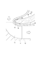
図1は、一実施形態に係るターボチャージャ2(2A)の回転軸線Oに沿った模式的な概略断面図である。図2は、ターボチャージャ2(2A)におけるタービンハウジング6の構成例を模式的に示す斜視図である。
FIG. 1 is a schematic schematic cross-sectional view taken along the rotation axis O of the turbocharger 2 (2A) according to the embodiment. FIG. 2 is a perspective view schematically showing a configuration example of the
図1に示すように、ターボチャージャ2は、タービンロータ4、タービンロータ4を収容するタービンハウジング6、タービンロータ4を回転可能に支持する軸受8、及び軸受8を収容する軸受ハウジング10を備える。
As shown in FIG. 1, the
タービンロータ4は、ハブ12及びハブ12の外周面に設けられた複数のタービン翼14を含む。タービンハウジング6は、入口フランジ16、インナーハウジング18、出口フランジ20、軸受連結フランジ22、及びアウターフレーム24を含む。入口フランジ16には、排ガスの入口26が形成されており、不図示のエンジンの排ガスが入口26から流入するように構成されている。
The
インナーハウジング18は、板金製であり、入口フランジ16の入口26から流入した排ガスをタービンロータ4のタービン翼14に導くよう構成されている。インナーハウジング18は、タービンロータ4の外周側に設けられたスクロール部28と、タービン翼14の先端30に対向するシュラウド部32と、タービン翼14を通過した排ガスを出口フランジ20に形成された排ガスの出口34に導く出口側筒状部36とを含む。図示する例示的形態では、インナーハウジング18のスクロール部28は、入口フランジ16に溶接等の方法で固定されており、インナーハウジング18の出口側筒状部36は、出口フランジ20に溶接等の方法で固定されている。
The
上記のように、板金製のインナーハウジング18を用いることによって、タービンハウジング6のうち排ガスに面する部分の熱容量の増大を抑制し、エンジン始動時における排ガス浄化用触媒(不図示)の昇温時間を短縮することができる。
As described above, by using the sheet metal
出口フランジ20には、排ガスの出口34が形成されており、インナーハウジング18を通過した排ガスが出口34から排出されるよう構成される。軸受連結フランジ22は、軸受ハウジング10に設けられた軸受側フランジ23に締結具38によって締結され、これによりタービンハウジング6と軸受ハウジング10とが連結される。
An
次に、図1及び図2を用いてアウターフレーム24の構成について説明する。図2は、タービンハウジング6の構成例を模式的に示す斜視図である。
Next, the configuration of the
幾つかの実施形態では、図1及び図2に示すように、アウターフレーム24は、インナーハウジング18の外側に設けられた複数の支持部42を含み、入口フランジ16、出口フランジ20及び軸受連結フランジ22を複数の支持部42によって連結するよう構成されている。
In some embodiments, as shown in FIGS. 1 and 2, the
また、アウターフレーム24は、インナーハウジング18の外側に設けられた複数の支持部42によって入口フランジ16、出口フランジ20及び軸受連結フランジ22を連結しているため、特許文献1に記載されるような内側ハウジング全体を覆う外側ハウジングを設ける場合と比較して、タービンハウジング6の軽量化及び低コスト化を実現することができる。
Further, since the
また、複数の支持部42はインナーハウジング18の外側に設けられていてインナーハウジング18の内側を通る高温の排ガスに直接触れないため、アウターフレーム24の温度上昇を抑制することができ、アウターフレーム24の材料強度を高く保つことができる。したがって、アウターフレーム24の材料選択の自由度が高いというメリットもある。なお、アウターフレーム24は、入口フランジ16、出口フランジ20及び軸受連結フランジ22の各々に対し、例えば鋳造によって一体的に形成してもよいし、溶接によって接合してもよいし、ボルト等の締結具によって固定してもよい。
Further, since the plurality of
幾つかの実施形態では、図1及び図2に示すように、複数の支持部42は、入口フランジ16と出口フランジ20とを連結するよう構成された柱状の第1支持部42a、入口フランジ16と軸受連結フランジ22とを連結するよう構成された柱状の第2支持部42b、及び、出口フランジ20と軸受連結フランジ22とを連結するよう構成された柱状の第3支持部42c、のうち、2種以上の支持部42を含む。図2に示す例示的形態では、複数の支持部42は、第1支持部42a、第2支持部42b及び第3支持部42cを含む。
In some embodiments, as shown in FIGS. 1 and 2, the plurality of
このように、第1支持部42a、第2支持部42b及び第3支持部42cのうち2種以上の支持部42によって、入口フランジ16、出口フランジ20及び軸受連結フランジ22を連結することで、タービンハウジング6の剛性を高めるとともに軽量化を実現することができる。
In this way, the
幾つかの実施形態では、図2に示すように、複数の支持部42は、出口フランジ20と軸受連結フランジ22とを連結するよう構成された複数の柱状の第3支持部42cを含み、複数の第3支持部42cは、タービンロータ4の周方向に間隔をあけて配置されている。また、複数の支持部42は、インナーハウジング18のスクロール部28の外周面40に沿ってタービンロータ4の周方向に延在する複数の柱状の第4支持部42dを含み、第4支持部42は、互いに隣接する二つの第3支持部42cを連結するように、タービンロータ4の周方向に順に配置されている。また、複数の支持部42は、複数の第3支持部42のうち入口フランジ16に隣接する第3支持部42cと入口フランジ16とを連結するように、インナーハウジング18のスクロール部28の外周面40に沿って延在する柱状の第5支持部42eを含む。
In some embodiments, as shown in FIG. 2, the plurality of
このように、第1〜第5支持部42(42〜42e)によって入口フランジ16、出口フランジ20及び軸受連結フランジ22を連結することで、タービンハウジング6の剛性を高めるとともに軽量化を実現することができる。
In this way, by connecting the
幾つかの実施形態では、図1及び図2に示すタービンハウジング6において、アウターフレーム24を構成する材料は、インナーハウジング18を構成する材料よりも耐酸化性及び耐熱性に劣る。例えば、インナーハウジング18を構成する材料としてオーステナイト系ステンレス鋼等の耐熱鋼を使用し、アウターフレーム24を構成する材料としてインナーハウジング18の構成材料よりもニッケル含有量の低いステンレス鋼、アルミニウム、又は樹脂等の耐熱性の低い材料を使用してもよい。
In some embodiments, in the
複数の支持部42を含むアウターフレーム24はインナーハウジング18の外側に設けられていてインナーハウジング18の内側を通る高温の排ガスに直接触れないため、上記のようにインナーハウジング18を構成する材料よりも耐酸化性に劣る低級材をアウターフレーム24に使用しても、アウターフレーム24の腐食は生じにくい。したがって、タービンハウジング6に要求される性能を満たしつつタービンハウジング6の低コスト化を実現することができる。
Since the
次に、図3〜図5を用いてターボチャージャ2の幾つかの変形例について説明する。図3は、一実施形態に係るターボチャージャ2(2B)の回転軸線Oに沿った模式的な概略断面図である。図4は、一実施形態に係るターボチャージャ2(2C)の回転軸線Oに沿った模式的な概略断面図である。図5は、一実施形態に係るターボチャージャ2(2D)の回転軸線Oに沿った模式的な概略断面図である。
Next, some modifications of the
以下で説明するターボチャージャ2(2B〜2D)は、上述したターボチャージャ2(2A)と基本的構成は同様であるが、タービンハウジング6が更なる付加的構成を有する点が異なる。以下の変形例では、ターボチャージャ2(2A)の各構成と同様の構成については同一の符号を付して説明を省略し、各変形例の特徴的な構成を中心に説明する。
The turbochargers 2 (2B to 2D) described below have the same basic configurations as the turbochargers 2 (2A) described above, except that the
幾つかの実施形態では、図3に示すように、タービンハウジング6は、インナーハウジング18の外周面40に沿って配置された断熱部44を備える。
In some embodiments, as shown in FIG. 3, the
インナーハウジング18は、高温の排ガスによって短時間で昇温するため、インナーハウジング18から外部への輻射熱の熱量は大きくなりやすい。そこで、上記のように、インナーハウジング18の外周面40に沿って配置された断熱部44を設けることにより、輻射熱に起因するタービン性能の低下を抑制することができる。また、アウターフレーム24とともに断熱部44を設けることで、断熱部44の形状や剛性の自由度が高くなり、断熱部44の施工が容易となる。
Since the
幾つかの実施形態では、図3に示す構成において、断熱部44はステンレス又はアルミニウム等の金属製のシート材を含む。かかる構成によれば、インナーハウジング18の外周面40の広い範囲をシート材によって容易に覆うことができ、インナーハウジング18からの輻射熱を効果的に断熱することができる。
In some embodiments, in the configuration shown in FIG. 3, the
幾つかの実施形態では、図3に示す構成において、断熱部44は、セラミックファイバー等の繊維系の断熱材を含む。かかる構成によれば、繊維系の断熱材が内部に空気を含むため、重量の増大を抑制しつつインナーハウジング18からの輻射熱を効果的に断熱することができる。
In some embodiments, in the configuration shown in FIG. 3, the
幾つかの実施形態では、図4に示すように、タービンハウジング6は、インナーハウジング18のスクロール部28の少なくとも一部を覆うように構成された防護壁部46を備える。図示する形態では、タービンロータ4の軸方向における防護壁部46の存在範囲S1とタービンロータ4の軸方向におけるタービン翼14の存在範囲S2とが少なくとも部分的に重複するように、防護壁部46が設けられている。
In some embodiments, as shown in FIG. 4, the
かかる構成によれば、スクロール部28の少なくとも一部を覆う防護壁部46によって、ターボチャージャ2のコンテイメント性(損傷した内部部品の外部への飛び出しを防止する遮蔽性)を高めることができる。これにより、タービン翼14がバーストしてもタービン翼14の破片がタービンハウジング6の外部へ飛び出すことを防止することができる。また、複数の支持部42と防護壁部46との併用により、防護壁部46を必要な部分にのみ設けることができるため、タービンハウジング6の軽量化及び低コスト化を実現することができる。
According to such a configuration, the
幾つかの実施形態では、図4に示す構成において、防護壁部46は、タービンロータ4の周方向における全周に亘ってスクロール部28を覆うように構成される。
In some embodiments, in the configuration shown in FIG. 4, the
かかる構成によれば、全周に亘ってスクロール部28を覆う防護壁部46によって、ターボチャージャ2のコンテイメント性を一層高めることができる。これにより、タービン翼14がバーストしてもタービン翼14の破片がタービンハウジング6の外部へ飛び出すことを効果的に防止することができる。
According to such a configuration, the contentability of the
幾つかの実施形態では、図4に示すように、防護壁部46は支持部42に支持される。図示する例示的形態では、防護壁部46は、第2支持部42bに片持ち支持される。
In some embodiments, the
かかる構成によれば、タービン翼14がバーストしてタービン翼14の破片が防護壁部46に衝突した場合に、防護壁部46が受けた荷重が支持部42に伝達され、タービン翼14の破片を防護壁部46及び支持部42によって効果的に受け止めることができる。
According to this configuration, when the
幾つかの実施形態では、図4に示す構成において、アウターフレーム24と防護壁部46とは、同一材料で一体的に形成される。かかる構成によれば、タービンハウジング6の優れた製造性を実現することができる。
In some embodiments, in the configuration shown in FIG. 4, the
幾つかの実施形態では、図5に示すように、タービンハウジング6は、インナーハウジング18のうちタービンロータ4のタービン翼14の先端30に対向するシュラウド部32をインナーハウジング18の外側から支持するよう構成されたシュラウド保持部48を備える。
In some embodiments, as shown in FIG. 5, the
インナーハウジング18は板金製で変形しやすいため、高速回転するタービンロータ4のタービン翼14の先端30とインナーハウジング18のシュラウド部32との接触リスクや、タービン翼14の先端30とシュラウド部32とのクリアランスの増大によるタービン性能の低下リスクがある。そこで、上記のように、インナーハウジング18の外側から支持するよう構成されたシュラウド保持部48を設けることにより、インナーハウジング18のシュラウド部32の変形を抑制し、上記二つのリスクを低減することができる。
Since the
幾つかの実施形態では、図5に示す構成において、シュラウド保持部48を構成する材料は、アウターフレーム24を構成する材料よりも高温強度が高い。例えば、シュラウド保持部48を構成する材料としてオーステナイト系ステンレス鋼等の耐熱鋼を使用し、アウターフレーム24を構成する材料としてインナーハウジング18の構成材料よりもニッケル含有量の低いステンレス鋼、アルミニウム、又は樹脂等の耐熱性の低い材料を使用してもよい。
In some embodiments, in the configuration shown in FIG. 5, the material constituting the
図5に示す構成では、シュラウド保持部48はインナーハウジング18の外側からシュラウド部32を支持するため、高温となるシュラウド部32からの伝熱の影響を受けやすい。そこで、上記のように、シュラウド保持部48を構成する材料の高温強度を、アウターフレーム24を構成する材料の高温強度より高くすることにより、シュラウド保持部48の熱変形を抑制しつつ、アウターフレーム24に比較的安価な材料を使用して低コスト化を図ることができる。
In the configuration shown in FIG. 5, since the
幾つかの実施形態では、図5に示すように、シュラウド保持部48は支持部42に支持される。図示する例示的形態では、シュラウド保持部48は、第1支持部42aに片持ち支持される。かかる構成によれば、タービンハウジング6の構成を簡素化することができる。
In some embodiments, the
幾つかの実施形態では、図5に示す構成において、複数の支持部42とシュラウド保持部48とは、同一材料で一体的に形成される。かかる構成によれば、タービンハウジング6の部品点数を削減するとともにタービンハウジング6の優れた製造性を実現することができる。
In some embodiments, in the configuration shown in FIG. 5, the plurality of
図6は、シュラウド保持部48の構成の一例を示す拡大図である。図7は、シュラウド保持部48の構成の他の一例を示す拡大図である。
FIG. 6 is an enlarged view showing an example of the configuration of the
幾つかの実施形態では、図6に示すように、インナーハウジング18のシュラウド部32とシュラウド保持部48との間に断熱部50を設けて、断熱部50を構成する材料に、シュラウド保持部48を構成する材料よりも高温強度が高い材料を使用してもよい。これにより、高温となるシュラウド部32からの伝熱の影響をシュラウド保持部48が受けにくくなる。
In some embodiments, as shown in FIG. 6, a
幾つかの実施形態では、図7に示すように、シュラウド保持部48のうちシュラウド部32と当接する部分52の表面に複数の凸凹形状54を設けて、シュラウド保持部48とシュラウド部32との接触面積が小さくなるよう構成してもよい。これにより、高温となるシュラウド部32からの伝熱の影響をシュラウド保持部48が受けにくくなる。
In some embodiments, as shown in FIG. 7, a plurality of uneven shapes 54 are provided on the surface of the portion 52 of the
本発明は上述した実施形態に限定されることはなく、上述した実施形態に変形を加えた形態や、これらの形態を適宜組み合わせた形態も含む。 The present invention is not limited to the above-described embodiment, and includes a modified form of the above-described embodiment and a combination of these embodiments as appropriate.
2 ターボチャージャ
4 タービンロータ
6 タービンハウジング
8 軸受
10 軸受ハウジング
12 ハブ
14 タービン翼
16 入口フランジ
18 インナーハウジング
20 出口フランジ
22 軸受連結フランジ
23 軸受側フランジ
24 アウターフレーム
26 入口
28 スクロール部
30 先端
32 シュラウド部
34 出口
36 出口側筒状部
38 締結具
40 外周面
42 支持部
42a 第1支持部
42b 第2支持部
42c 第3支持部
42d 第4支持部
42e 第5支持部
44 断熱部
46 防護壁部
48 シュラウド保持部
50 断熱部
52 当接する部分
54 凸凹形状
Claims (15)
排ガスの入口が形成された入口フランジと、
前記入口から流入した前記排ガスを前記タービンロータに導くよう構成された板金製のインナーハウジングと、
前記インナーハウジングを通過した前記排ガスの出口が形成された出口フランジと、
前記タービンロータを回転可能に支持する軸受を収容する軸受ハウジングに連結される軸受連結フランジと、
前記インナーハウジングの外側に設けられた複数の柱状の支持部を含み、前記入口フランジ、前記出口フランジ及び前記軸受連結フランジを前記複数の柱状の支持部によって連結するよう構成されたアウターフレームと、
を備え、
前記複数の柱状の支持部は、前記入口フランジと前記出口フランジとを連結するよう構成された第1支持部、前記入口フランジと前記軸受連結フランジとを連結するよう構成された第2支持部、及び、前記出口フランジと前記軸受連結フランジとを連結するよう構成された第3支持部を含み、
前記第3支持部は、前記タービンロータの周方向に沿って互いに間隔を置いて複数配置されているタービンハウジング。 A turbine housing for accommodating a turbine rotor
An inlet flange with an exhaust gas inlet and
An inner housing made of sheet metal configured to guide the exhaust gas flowing in from the inlet to the turbine rotor, and
An outlet flange on which an exhaust gas outlet that has passed through the inner housing is formed,
A bearing connecting flange connected to a bearing housing that houses a bearing that rotatably supports the turbine rotor,
An outer frame including a plurality of columnar support portions provided on the outside of the inner housing, and configured to connect the inlet flange, the outlet flange, and the bearing connecting flange by the plurality of columnar support portions.
Equipped with a,
The plurality of columnar support portions include a first support portion configured to connect the inlet flange and the outlet flange, and a second support portion configured to connect the inlet flange and the bearing connecting flange. Including a third support portion configured to connect the outlet flange and the bearing connecting flange .
A plurality of the third support portions are arranged at intervals along the circumferential direction of the turbine rotor .
前記第1支持部と前記第3支持部とは、前記タービンロータの周方向に沿って互いに離間している、請求項1に記載のタービンハウジング。 The first support portion and the second support portion are separated from each other along the axial direction of the turbine rotor.
The turbine housing according to claim 1, wherein the first support portion and the third support portion are separated from each other along the circumferential direction of the turbine rotor .
排ガスの入口が形成された入口フランジと、
前記入口から流入した前記排ガスを前記タービンロータに導くよう構成された板金製のインナーハウジングと、
前記インナーハウジングを通過した前記排ガスの出口が形成された出口フランジと、
前記タービンロータを回転可能に支持する軸受を収容する軸受ハウジングに連結される軸受連結フランジと、
前記インナーハウジングの外側に設けられた複数の支持部を含み、前記入口フランジ、前記出口フランジ及び前記軸受連結フランジを前記複数の支持部によって連結するよう構成されたアウターフレームと、
前記インナーハウジングのスクロール部の少なくとも一部を覆うように構成され、前記支持部に支持された防護壁部と、
を備えるタービンハウジング。 A turbine housing for accommodating a turbine rotor
An inlet flange with an exhaust gas inlet and
An inner housing made of sheet metal configured to guide the exhaust gas flowing in from the inlet to the turbine rotor, and
An outlet flange on which an exhaust gas outlet that has passed through the inner housing is formed,
A bearing connecting flange connected to a bearing housing that houses a bearing that rotatably supports the turbine rotor,
An outer frame including a plurality of support portions provided on the outer side of the inner housing and configured to connect the inlet flange, the outlet flange, and the bearing connecting flange by the plurality of support portions.
A protective wall portion configured to cover at least a part of the scroll portion of the inner housing and supported by the support portion, and a protective wall portion.
Turbine housing with.
排ガスの入口が形成された入口フランジと、
前記入口から流入した前記排ガスを前記タービンロータに導くよう構成された板金製のインナーハウジングと、
前記インナーハウジングを通過した前記排ガスの出口が形成された出口フランジと、
前記タービンロータを回転可能に支持する軸受を収容する軸受ハウジングに連結される軸受連結フランジと、
前記インナーハウジングの外側に設けられた複数の支持部を含み、前記入口フランジ、前記出口フランジ及び前記軸受連結フランジを前記複数の支持部によって連結するよう構成されたアウターフレームと、
前記インナーハウジングのうち前記タービンロータのタービン翼の先端に対向するシュラウド部を前記インナーハウジングの外側から支持するよう構成されたシュラウド保持部と、
を更に備えるタービンハウジング。 A turbine housing for accommodating a turbine rotor
An inlet flange with an exhaust gas inlet and
An inner housing made of sheet metal configured to guide the exhaust gas flowing in from the inlet to the turbine rotor, and
An outlet flange on which an exhaust gas outlet that has passed through the inner housing is formed,
A bearing connecting flange connected to a bearing housing that houses a bearing that rotatably supports the turbine rotor,
An outer frame including a plurality of support portions provided on the outer side of the inner housing and configured to connect the inlet flange, the outlet flange, and the bearing connecting flange by the plurality of support portions.
A shroud holding portion configured to support a shroud portion of the inner housing facing the tip of a turbine blade of the turbine rotor from the outside of the inner housing .
Turbine housing further equipped with.
A turbocharger comprising a turbine rotor and a turbine housing according to any one of claims 1 to 14.
Priority Applications (1)
| Application Number | Priority Date | Filing Date | Title |
|---|---|---|---|
| JP2017071802A JP6820222B2 (en) | 2017-03-31 | 2017-03-31 | Turbine housing and turbocharger |
Applications Claiming Priority (1)
| Application Number | Priority Date | Filing Date | Title |
|---|---|---|---|
| JP2017071802A JP6820222B2 (en) | 2017-03-31 | 2017-03-31 | Turbine housing and turbocharger |
Publications (2)
| Publication Number | Publication Date |
|---|---|
| JP2018173031A JP2018173031A (en) | 2018-11-08 |
| JP6820222B2 true JP6820222B2 (en) | 2021-01-27 |
Family
ID=64108415
Family Applications (1)
| Application Number | Title | Priority Date | Filing Date |
|---|---|---|---|
| JP2017071802A Expired - Fee Related JP6820222B2 (en) | 2017-03-31 | 2017-03-31 | Turbine housing and turbocharger |
Country Status (1)
| Country | Link |
|---|---|
| JP (1) | JP6820222B2 (en) |
Family Cites Families (8)
| Publication number | Priority date | Publication date | Assignee | Title |
|---|---|---|---|---|
| JPS6024839U (en) * | 1983-07-27 | 1985-02-20 | いすゞ自動車株式会社 | Turbocharger insulation structure |
| DE29909018U1 (en) * | 1999-05-26 | 2000-09-28 | Heinrich Gillet GmbH & Co. KG, 67480 Edenkoben | Turbine housing for exhaust gas turbochargers |
| JP4448064B2 (en) * | 2005-06-24 | 2010-04-07 | トヨタ自動車株式会社 | Turbine housing |
| JP4512058B2 (en) * | 2006-04-04 | 2010-07-28 | トヨタ自動車株式会社 | Turbine housing |
| CN102203390A (en) * | 2008-09-22 | 2011-09-28 | 柔性金属有限公司 | Fabricated turbine housing |
| DE102010005761A1 (en) * | 2010-01-25 | 2011-07-28 | Benteler Automobiltechnik GmbH, 33102 | exhaust assembly |
| JP5910114B2 (en) * | 2012-01-27 | 2016-04-27 | トヨタ自動車株式会社 | Turbine housing and exhaust turbine supercharger |
| JP6300675B2 (en) * | 2014-07-28 | 2018-03-28 | 株式会社三五 | Turbine housing |
-
2017
- 2017-03-31 JP JP2017071802A patent/JP6820222B2/en not_active Expired - Fee Related
Also Published As
| Publication number | Publication date |
|---|---|
| JP2018173031A (en) | 2018-11-08 |
Similar Documents
| Publication | Publication Date | Title |
|---|---|---|
| EP1287235B1 (en) | Casing assembly for the turbine of an exhaust turbocharger | |
| JP6126246B2 (en) | Turbine housing | |
| EP2508731B1 (en) | Sheet metal turbine housing | |
| US7074009B2 (en) | Casing assembly for the turbine of an exhaust turbochanger | |
| JP6580122B2 (en) | Turbocharger | |
| JP5113770B2 (en) | Turbocharger | |
| JP5338991B1 (en) | Turbine housing and exhaust turbine supercharger | |
| US8485314B2 (en) | Exhaust muffler | |
| JP5610067B2 (en) | Turbocharger turbine housing | |
| JP2012137068A (en) | Turbine scroll section structure | |
| CN108699912B (en) | Mixed-flow turbine of an exhaust-gas turbocharger and exhaust-gas turbine with a turbine | |
| EP2283218B1 (en) | Thermal insulation structure | |
| US10072523B2 (en) | Sheet-metal turbine housing | |
| JP6820222B2 (en) | Turbine housing and turbocharger | |
| JP6796214B2 (en) | Turbine and turbocharger equipped with it | |
| JP5342427B2 (en) | Sheet metal turbine housing | |
| JP2008196327A (en) | Turbocharger | |
| JP4471612B2 (en) | Method and apparatus for supporting a hot duct apparatus | |
| JP2011021573A (en) | Turbocharger | |
| JPH07139364A (en) | Turbocharger | |
| JP5518232B2 (en) | Sheet metal turbine housing | |
| JP7505650B2 (en) | Turbocharger | |
| US11313247B2 (en) | Turbine housing | |
| JP2019167963A (en) | Turbocharger | |
| JP2014118867A (en) | Turbocharger |
Legal Events
| Date | Code | Title | Description |
|---|---|---|---|
| A625 | Written request for application examination (by other person) |
Free format text: JAPANESE INTERMEDIATE CODE: A625 Effective date: 20190731 |
|
| A977 | Report on retrieval |
Free format text: JAPANESE INTERMEDIATE CODE: A971007 Effective date: 20200616 |
|
| A131 | Notification of reasons for refusal |
Free format text: JAPANESE INTERMEDIATE CODE: A131 Effective date: 20200630 |
|
| A521 | Request for written amendment filed |
Free format text: JAPANESE INTERMEDIATE CODE: A523 Effective date: 20200824 |
|
| TRDD | Decision of grant or rejection written | ||
| A01 | Written decision to grant a patent or to grant a registration (utility model) |
Free format text: JAPANESE INTERMEDIATE CODE: A01 Effective date: 20201208 |
|
| A61 | First payment of annual fees (during grant procedure) |
Free format text: JAPANESE INTERMEDIATE CODE: A61 Effective date: 20210104 |
|
| R150 | Certificate of patent or registration of utility model |
Ref document number: 6820222 Country of ref document: JP Free format text: JAPANESE INTERMEDIATE CODE: R150 |
|
| LAPS | Cancellation because of no payment of annual fees |