JP6811682B2 - Mass spectrometer and nozzle member - Google Patents
Mass spectrometer and nozzle member Download PDFInfo
- Publication number
- JP6811682B2 JP6811682B2 JP2017113622A JP2017113622A JP6811682B2 JP 6811682 B2 JP6811682 B2 JP 6811682B2 JP 2017113622 A JP2017113622 A JP 2017113622A JP 2017113622 A JP2017113622 A JP 2017113622A JP 6811682 B2 JP6811682 B2 JP 6811682B2
- Authority
- JP
- Japan
- Prior art keywords
- mass spectrometer
- sample
- branch portion
- nozzle
- flow
- Prior art date
- Legal status (The legal status is an assumption and is not a legal conclusion. Google has not performed a legal analysis and makes no representation as to the accuracy of the status listed.)
- Active
Links
Images


Classifications
-
- H—ELECTRICITY
- H01—ELECTRIC ELEMENTS
- H01J—ELECTRIC DISCHARGE TUBES OR DISCHARGE LAMPS
- H01J49/00—Particle spectrometers or separator tubes
- H01J49/02—Details
- H01J49/10—Ion sources; Ion guns
- H01J49/16—Ion sources; Ion guns using surface ionisation, e.g. field-, thermionic- or photo-emission
- H01J49/165—Electrospray ionisation
- H01J49/167—Capillaries and nozzles specially adapted therefor
-
- H—ELECTRICITY
- H01—ELECTRIC ELEMENTS
- H01J—ELECTRIC DISCHARGE TUBES OR DISCHARGE LAMPS
- H01J49/00—Particle spectrometers or separator tubes
- H01J49/02—Details
- H01J49/06—Electron- or ion-optical arrangements
-
- H—ELECTRICITY
- H01—ELECTRIC ELEMENTS
- H01J—ELECTRIC DISCHARGE TUBES OR DISCHARGE LAMPS
- H01J49/00—Particle spectrometers or separator tubes
- H01J49/02—Details
- H01J49/04—Arrangements for introducing or extracting samples to be analysed, e.g. vacuum locks; Arrangements for external adjustment of electron- or ion-optical components
- H01J49/0431—Arrangements for introducing or extracting samples to be analysed, e.g. vacuum locks; Arrangements for external adjustment of electron- or ion-optical components for liquid samples
-
- H—ELECTRICITY
- H01—ELECTRIC ELEMENTS
- H01J—ELECTRIC DISCHARGE TUBES OR DISCHARGE LAMPS
- H01J49/00—Particle spectrometers or separator tubes
- H01J49/02—Details
- H01J49/022—Circuit arrangements, e.g. for generating deviation currents or voltages ; Components associated with high voltage supply
-
- H—ELECTRICITY
- H01—ELECTRIC ELEMENTS
- H01J—ELECTRIC DISCHARGE TUBES OR DISCHARGE LAMPS
- H01J49/00—Particle spectrometers or separator tubes
- H01J49/02—Details
- H01J49/025—Detectors specially adapted to particle spectrometers
-
- H—ELECTRICITY
- H01—ELECTRIC ELEMENTS
- H01J—ELECTRIC DISCHARGE TUBES OR DISCHARGE LAMPS
- H01J49/00—Particle spectrometers or separator tubes
- H01J49/02—Details
- H01J49/04—Arrangements for introducing or extracting samples to be analysed, e.g. vacuum locks; Arrangements for external adjustment of electron- or ion-optical components
- H01J49/0431—Arrangements for introducing or extracting samples to be analysed, e.g. vacuum locks; Arrangements for external adjustment of electron- or ion-optical components for liquid samples
- H01J49/0445—Arrangements for introducing or extracting samples to be analysed, e.g. vacuum locks; Arrangements for external adjustment of electron- or ion-optical components for liquid samples with means for introducing as a spray, a jet or an aerosol
-
- H—ELECTRICITY
- H01—ELECTRIC ELEMENTS
- H01J—ELECTRIC DISCHARGE TUBES OR DISCHARGE LAMPS
- H01J49/00—Particle spectrometers or separator tubes
- H01J49/02—Details
- H01J49/24—Vacuum systems, e.g. maintaining desired pressures
-
- H—ELECTRICITY
- H01—ELECTRIC ELEMENTS
- H01J—ELECTRIC DISCHARGE TUBES OR DISCHARGE LAMPS
- H01J49/00—Particle spectrometers or separator tubes
- H01J49/26—Mass spectrometers or separator tubes
-
- H—ELECTRICITY
- H01—ELECTRIC ELEMENTS
- H01J—ELECTRIC DISCHARGE TUBES OR DISCHARGE LAMPS
- H01J49/00—Particle spectrometers or separator tubes
- H01J49/26—Mass spectrometers or separator tubes
- H01J49/34—Dynamic spectrometers
- H01J49/42—Stability-of-path spectrometers, e.g. monopole, quadrupole, multipole, farvitrons
Landscapes
- Chemical & Material Sciences (AREA)
- Analytical Chemistry (AREA)
- Dispersion Chemistry (AREA)
- Physics & Mathematics (AREA)
- Engineering & Computer Science (AREA)
- Plasma & Fusion (AREA)
- Other Investigation Or Analysis Of Materials By Electrical Means (AREA)
- Electron Tubes For Measurement (AREA)
Description
本開示は、質量分析装置およびそれに用いられるノズル部材に関する。 The present disclosure relates to a mass spectrometer and a nozzle member used therein.
従来、大気圧下で試料をイオン化するイオン化室と高真空雰囲気下でイオンを選択する分析室との間に一つまたは複数の中間真空室を設けた多段差動排気系を有する質量分析装置がある。中間真空室には、試料ガスの流通路となる開口が設けられている。イオン化室と中間真空室とでは大きな圧力差があるため、試料ガスは上記開口を通過して圧力が低い中間真空室へ流入する際に超音速自由噴流となって、マッハディスク(衝撃波)およびバレルショックが形成される。 Conventionally, a mass spectrometer having a multi-stage differential exhaust system in which one or more intermediate vacuum chambers are provided between an ionization chamber for ionizing a sample under atmospheric pressure and an analysis chamber for selecting ions in a high vacuum atmosphere. is there. The intermediate vacuum chamber is provided with an opening that serves as a flow path for the sample gas. Since there is a large pressure difference between the ionization chamber and the intermediate vacuum chamber, the sample gas becomes a supersonic free jet when it passes through the above opening and flows into the intermediate vacuum chamber with low pressure, and becomes a Mach disk (shock wave) and barrel. A shock is formed.
図1は、膨張した噴流の構造を示す図である。試料ガスは圧力差が大きい室間を移動する際に膨張波を生成する。マッハディスクは、膨張波が噴流の境界で反射し、反射波が干渉して増幅することによって生成される。つまり、マッハディスクは噴流の圧力または密度が高い位置を指す。マッハディスクが繰り返し生成されると、質量分析装置の検出感度の低下を招くと考えられている。 FIG. 1 is a diagram showing the structure of an expanded jet. The sample gas generates an expansion wave when moving between chambers with a large pressure difference. The Mach disk is generated by the expansion wave being reflected at the boundary of the jet and the reflected wave interfering and amplifying. That is, the Mach disc points to a position where the pressure or density of the jet is high. It is believed that repeated generation of Mach disks causes a decrease in the detection sensitivity of the mass spectrometer.
特許文献1には、イオン化室から第1中間真空室へイオンを送る加熱パイプの出口孔の外側に、通路が円錐形状である整流ノズルを設けたイオン輸送装置が記載されている。当該イオン輸送装置は、ノズルの円形開口の径を、該ノズルがないと仮定したときに超音速自由噴流により形成されるマッハディスクの径よりも小さく設定することにより、マッハディスクの生成を抑制する。
ところで、超音速自由噴流の境界の形状は、イオン化室の圧力と中間真空室の圧力との比によって変化する。そのため、特許文献1に記載されたイオン輸送装置では、ノズルの円形開口の径が上記圧力比に基づいて設計される。したがって、特許文献1に記載された発明では、装置完成後にイオン化室および第1中間真空室の圧力が変化する場合、マッハディスクの生成が十分に抑制できなくなる可能性がある。
By the way, the shape of the boundary of the supersonic free jet changes depending on the ratio of the pressure in the ionization chamber to the pressure in the intermediate vacuum chamber. Therefore, in the ion transport device described in
一方、生体内試料の分析等、高い感度を要求される質量分析を質量分析装置が実施する場合、マッハディスクの生成は十分に抑制される必要がある。 On the other hand, when a mass spectrometer performs mass spectrometry that requires high sensitivity, such as analysis of an in-vivo sample, it is necessary to sufficiently suppress the generation of Mach disks.
本開示は、上記の点に鑑みてなされたものであり、質量分析装置の広範な稼働条件に対してマッハディスクの生成を抑制できる技術を提供する。 The present disclosure has been made in view of the above points, and provides a technique capable of suppressing the generation of Mach disks under a wide range of operating conditions of a mass spectrometer.
上記課題を解決するために、代表的な発明の一つとして、試料をイオン化するイオン化部と、前記イオン化部と流通管によって接続されイオン化された前記試料が流入する流入口と、流入した前記試料が流出する流出口と、を有するノズル部と、真空排気手段によって排気された、前記ノズル部から前記試料が流入する真空室と、前記真空室より前記試料の流れの下流に位置し、前記試料からイオンを選択する質量分析部と、前記質量分析部が選択したイオンを検出するイオン検出部と、を備える質量分析装置であって、前記ノズル部の内部には、前記試料の流れを分岐する分岐部が設けられ、前記分岐部は前記流出口に向かうにつれて径が小さくなるテーパー形状の凸部を有する質量分析装置を提供する。 In order to solve the above-mentioned problems, as one of the representative inventions, an ionizing section for ionizing a sample, an inlet connected to the ionizing section by a flow pipe and an inflow port of the ionized sample, and the inflowing sample. The sample is located downstream of the flow of the sample from the vacuum chamber, the vacuum chamber having the outlet having the outflow port, the vacuum chamber from which the sample flows in from the nozzle portion exhausted by the vacuum exhaust means, and the sample. A mass spectrometer including a mass spectrometer that selects ions from the sample and an ion detection unit that detects the ions selected by the mass spectrometer, and the flow of the sample is branched inside the nozzle unit. A mass spectrometer is provided in which a branch portion is provided, and the branch portion has a tapered convex portion whose diameter decreases toward the outlet.
また、代表的な発明の別の一つとして、質量分析装置に用いるノズル部材であって、イオン化された試料が流入する流入口と、流入した前記試料が流出する流出口と、を有し、前記試料の流れを分岐する分岐部が内部に設けられ、前記分岐部は前記流出口に向かうにつれて径が小さくなるテーパー形状の凸部を有するノズル部材を提供する。 Further, as another typical invention, the nozzle member used in the mass spectrometer has an inflow port into which the ionized sample flows in and an outflow port into which the inflowing sample flows out. A branch portion for branching the flow of the sample is provided inside, and the branch portion provides a nozzle member having a tapered convex portion whose diameter decreases toward the outlet.
さらに、代表的な発明の別の一つとして、試料をイオン化するイオン化部と、前記イオン化部と流通管によって接続されイオン化された前記試料が流入する流入口と、流入した前記試料が流出する流出口と、を有するノズル部と、真空排気手段によって排気された、前記ノズル部から前記試料が流入する真空室と、前記真空室より前記試料の流れの下流に位置し、前記試料からイオンを選択する質量分析部と、前記質量分析部が選択したイオンを検出するイオン検出部と、を備える質量分析装置であって、前記ノズル部の内部には、前記試料の流れを分岐する分岐部が設けられ、前記分岐部は、分岐された前記試料の流れを交差させて前記真空室に流入させる質量分析装置を提供する。 Further, as another typical invention, an ionizing section for ionizing a sample, an inlet connected to the ionizing section by a flow tube for the ionized sample to flow in, and a flow for the inflowing sample to flow out. A nozzle portion having an outlet, a vacuum chamber in which the sample flows in from the nozzle portion exhausted by the vacuum exhaust means, and an ion located downstream of the flow of the sample from the vacuum chamber and selecting ions from the sample. A mass spectrometer including a mass spectrometric unit and an ion detection unit that detects ions selected by the mass spectrometric unit, and a branching unit for branching the flow of the sample is provided inside the nozzle unit. The branching portion provides a mass spectrometer that crosses the flow of the branched sample and allows it to flow into the vacuum chamber.
本開示によれば、質量分析装置の広範な稼働条件に対してマッハディスクの生成を抑制できる。上記以外の課題、構成および効果は、以下の実施の形態の説明により明らかにされる。 According to the present disclosure, the generation of Mach disks can be suppressed under a wide range of operating conditions of the mass spectrometer. Issues, configurations and effects other than the above will be clarified by the following description of embodiments.
以下、図面に基づいて、本開示の実施例を説明する。なお、本開示の実施例は、後述する実施例に限定されるものではなく、その技術思想の範囲において、種々の変形が可能である。また、後述する各実施例の説明に使用する各図の対応部分には同一の符号を付して示し、重複する説明を省略する。 Hereinafter, examples of the present disclosure will be described with reference to the drawings. The examples of the present disclosure are not limited to the examples described later, and various modifications can be made within the scope of the technical idea. Further, the corresponding parts of the drawings used in the description of each embodiment described later are designated by the same reference numerals, and duplicate description will be omitted.
<実施例>
[質量分析装置の構成]
図2は、実施例に係る質量分析装置Sの構成の概略図である。この明細書では、トリプル四重極質量分析装置を例にとって実施例の質量分析装置Sを説明する。質量分析装置Sは、前処理部1、イオン化部2、ノズル部3、真空室4、衝突室5、質量分析部6、イオン検出部7、データ処理部8、表示部9およびユーザ入力部10を備える。また、真空室4、衝突室5および質量分析部6は、それぞれ、排気手段であるポンプPと接続され、室内に四重極の電極11、12および13を備える。質量分析装置Sは、上記電極11、12および13に電圧を印加する電圧源14と上記電圧を制御する制御部15とを備える。
<Example>
[Mass spectrometer configuration]
FIG. 2 is a schematic diagram of the configuration of the mass spectrometer S according to the embodiment. In this specification, the mass spectrometer S of the embodiment will be described by taking the triple quadrupole mass spectrometer as an example. The mass spectrometer S includes a
前処理部1は、例えば、ガスクロマトグラフィー(GC)または液体クロマトグラフィー(LC)であり、質量分析対象の試料を時間的に分離または分画する。イオン化部2は、前処理部1から流れてきた試料を順次イオン化する。なお、イオン化された試料はガス状または気相である。
The
ノズル部3は、イオン化部2と図示しない流通管によって接続され、イオン化された試料が流入する流入口と、流入した試料が流出する流出口と、を有する。上記流出口は、真空室4に設けられた開口部のうちの一つと一致する。また、ノズル部3の内部には、流入口3a側から流出口3b側へ延伸し、試料の流れを分岐する分岐部が設けられている。上記分岐部の存在により、試料の流れはノズル部3内にて複数に分岐する。なお、ノズル部3は例えば、SUSなどの金属材料で形成されている。
The
真空室4は、ポンプPによって排気され、上述したように四重極の電極11を備える。ポンプPには、例えばロータリーポンプまたはターボ分子ポンプを使用する。上記電極11には交流電圧が印加され、ノズル部3から真空室4に流入した試料のうち特定の範囲の質量対電価比(m/Z比)のイオン(プリカーサーイオン)が真空室4を通過する。ここで、mはイオン質量であり、Zはイオンの帯電価数である。真空室4は、例えば、イオンガイドとして機能する。
The
ここで、ノズル部3の流入口に接続された流通管より上流の圧力はほぼ大気圧と同程度であり、真空室4の圧力は数パスカル程度である。具体的には、流通管内の圧力P1と真空室4内の圧力P2との比P1/P2は、例えば、50倍以上である。試料が上記の圧力差がある室間を移動する際に、膨張波は生成する。
Here, the pressure upstream from the flow pipe connected to the inlet of the
衝突室5は、ポンプPによって排気された後、例えば、ヘリウムやアルゴンといった不活性ガスが充填される。真空室4を通過したプリカーサーイオンは、ヘリウムやアルゴンと衝突することによって、化学結合が切断されてフラグメントイオンへと分割される。上述のように衝突室5には電極12が設けられており、電極12に電圧を印加することによって上記フラグメントイオンを加速し、質量分析部6へと輸送する。
After being exhausted by the pump P, the collision chamber 5 is filled with an inert gas such as helium or argon. The precursor ion that has passed through the
質量分析部6は、ポンプPによって排気され高真空状態となっている。質量分析部6は、例えば、mPa程度のオーダーの真空状態である。質量分析部6は四重極の電極13を備え、上記電極13に直流電圧Uと交流電圧VRFCOS(ΩRFt+RF)とが印加されることによって、フラグメントイオンのうちm/Z比が特定の範囲にあるイオンが選択される。
The
イオン検出部7は、質量分析部6において選択されたイオンの組成比および質量等を検出する。イオン検出部7は、取得したデータをデータ処理部8に通知する。データ処理部8は、イオン検出部7から取得したデータを分析する。データ処理部8は、例えば、予め記録されたデータベースと照合することによって、フラグメンテーションが起きる前のイオンを同定する。データ処理部8は、分析結果を表示部9に表示する。
The ion detection unit 7 detects the composition ratio, mass, and the like of the ions selected by the
表示部9は、データ処理部8から取得した質量分析データを表示する。表示部9には、例えば、試料に含まれる物質名およびその質量比などが質量分析データとして表示される。また、表示部9は、ユーザがユーザ入力部10を介して入力した質量分析装置Sの各種設定項目を表示する。ユーザ入力部10は、ユーザからの入力を受け付ける。ユーザは、例えば、真空室4、衝突室5及び質量分析部6が備える四重極の電極11〜13に印加する電圧をユーザ入力部10に入力する。電圧源14は、ユーザが設定した値の電圧を各電極11〜13に印加する。また、ユーザ入力部10は、真空室4、衝突室5および質量分析部6の室内圧力に関する入力を受け付ける。実施例の質量分析装置Sは、上記各室内の圧力が変更可能である。
The display unit 9 displays the mass spectrometry data acquired from the
制御部8は、上記の試料のイオン化、試料イオンビームの質量分析部6への輸送または入射、質量分離、イオン検出、データ処理およびユーザ入力部10が受け付けた入力の処理等を制御する。
The
[イオン選択の方法]
続いて、質量分析装置Sがイオン化された試料から特定のイオンを選択する方法について説明する。
[Ion selection method]
Subsequently, a method in which the mass spectrometer S selects a specific ion from the ionized sample will be described.
図3は、質量分析装置Sが備える電極11、12および13を詳細に示した図である。図3では、例として、各電極11、12および13のそれぞれが四本の棒状電極から成る四重極質量分析計(QMS:quadrupole mass spectrometer)が示されている。なお、電極の構成はQMS以外にも四本以上の棒状電極で構成される多重極質量分析計としてもよい。また、四本の棒状電極は、円柱形状の電極でもよく、一組の電極のそれぞれの対向面が双極面形状をした電極でもよい。
FIG. 3 is a diagram showing in detail the
図3に示すように、真空室4及び衝突室5が備える電極には、例えば、交流電圧のみが印加される。具体的には、2組の電極のうち、一方の組の電極には、交流電圧+ΦRF=VCOSWtが印加され、もう一方の組の電極には、上記交流電圧の逆位相である―ΦRF=―VCOSWtが印加される。ここで、図3に示すように組となっている2本の電極は互いに向き合っている。上記電圧の印加によって生じた電場は、帯電したイオンを振動させる一方で、中性の粒子には作用しない。したがって、帯電したイオンは真空室4および衝突室5を通過する一方、中性の粒子はほとんど当該室を通過しない。
As shown in FIG. 3, for example, only an AC voltage is applied to the electrodes provided in the
一方、質量分析部6が備える電極には、例えば、直流電圧と交流電圧との双方が印加される。具体的には、2組の電極のうち、一方の組の電極には、直流電圧と交流電圧との和+ΦDC+RF=U+VqCOSWqtが印加され、もう一方の組の電極には、上記電圧の逆位相である―ΦDC+RF=―U―VqCOSWqtが印加される。ここで、図3に示すように組となっている2本の電極は互いに向き合っている。上記電圧の印加によって生じた電場は、m/Z比が特定の範囲または特定の値にあるイオンを通過させる一方で、それ以外のイオンを通過させない。
On the other hand, for example, both a DC voltage and an AC voltage are applied to the electrodes included in the
質量分析部6がイオンを選択する仕組みについて図4および図5を参照しながらさらに詳細に説明する。上記電圧が印加された四本の棒状電極間には、次式に示す高周波電界ExおよびEyが生成される。
The mechanism by which the

イオン化された試料は、質量分析部6が備える電極間の中心軸(図中z軸方向)に沿って導入され、式(1)に示される高周波電界の中を通過する。上記高周波電界中のイオンのx軸方向およびy軸方向の軌道の安定性は、イオンの運動方程式(Mathieu方程式)から導かれる下記の無次元パラメータaおよびqによって決まる。
The ionized sample is introduced along the central axis (the z-axis direction in the figure) between the electrodes included in the
ここで、無次元パラメータaおよびqは、QMSにおける安定性パラメータである。また、式(2)および式(3)におけるr0は対向する電極間の距離の半値、eは素電荷、m/Zはイオンの質量対電荷比、Uは電極13に印加する直流電圧、VRFは高周波電圧の振幅、ΩRFは角振動周波数を示す。r0、U、VRFおよびΩRFの値が決まると、各イオン種はその質量対電荷比m/Zに応じて、a-q平面上の異なる(a、q)点に対応する。イオン種が質量分析部6を通過してイオン検出部7にて検出されるための直流電圧と交流電圧の値の組の集合は、a-q平面上で領域を形成する。上記領域は安定領域と称される。
Here, the dimensionless parameters a and q are stability parameters in the QMS. Further, in equations (2) and (3), r 0 is the half value of the distance between the opposing electrodes, e is the elementary charge, m / Z is the mass-to-charge ratio of the ion, and U is the DC voltage applied to the
図4はa-q平面を示す図である。図4(a)はa-q平面の全体を示す図、図4(b)はa-q平面内の四つの領域の境界点付近を拡大した図である。図4(a)および(b)において陰影がついている箇所が安定領域である。図4(a)において示された直線は、式(2)および式(3)から導出された以下の式4が示す直線である。
FIG. 4 is a diagram showing an aq plane. FIG. 4A is a view showing the entire aq plane, and FIG. 4B is an enlarged view of the vicinity of the boundary points of the four regions in the aq plane. The shaded areas in FIGS. 4 (a) and 4 (b) are stable regions. The straight line shown in FIG. 4A is a straight line shown by the
式(4)からわかるとおり、直流電圧Uおよび交流電圧の振幅VRFを変化させることによって、直線の傾きが変化する。直流電圧の値Uを大きくすると直線の傾きが大きくなり、直線は安定領域と交わらなくなる。つまり、直流電圧Uが大きいほどイオンは質量分析部6を通過できなくなる。また、交流電圧の振幅VRFが大きいほど直線の傾きは小さくなり、直線は安定領域と交わるようになる。つまり、交流電圧の振幅VRFが大きいほどイオンは質量分析部6を通過しやすくなる。
As can be seen from the equation (4), the slope of the straight line changes by changing the amplitude V RF of the DC voltage U and the AC voltage. When the value U of the DC voltage is increased, the slope of the straight line becomes large, and the straight line does not intersect the stable region. That is, the larger the DC voltage U, the more the ions cannot pass through the
ここで、式(2)および式(3)に示されているように、印加する電圧が固定されると(a、q)点は質量対電荷比と1対1に対応する。したがって、直線の内、安定領域と交わる部分が短ければ、より少ないイオン種しか質量分析部6を通過しなくなる。特に、直線が安定領域と不安定領域との境界点を通過するように電圧UおよびVRFが設定された場合、一種類のイオンのみが質量分析部6を通過できる。
Here, as shown in the equations (2) and (3), when the applied voltage is fixed, the points (a, q) correspond to the mass-to-charge ratio 1: 1. Therefore, if the portion of the straight line that intersects the stable region is short, only a smaller number of ion species will pass through the
具体的には、一部のイオンは電極13a、13b、13c、13d間を振動しながら質量分析部6を通過するのに対して、別の一部のイオンは振動が発散して、図3に示したx軸方向またはy軸方向に出射する。このように、質量分析装置Sは、印加する電圧を調節することによって、検出したいイオンを変更できる。
Specifically, some ions pass through the
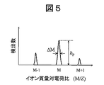
図5は、イオン種毎の検出数を示すスペクトルデータである。図5に示したイオン種M−1、M、M+1は、それぞれ、図4(b)の直線上に示したM−1、M、M+1に対応する。図5に示されているように、安定領域上の点であるイオンMは、不安定領域の上に位置するイオンM−1およびイオンM+1よりも多数検出されている。 FIG. 5 is spectral data showing the number of detections for each ion species. The ion species M-1, M, and M + 1 shown in FIG. 5 correspond to M-1, M, and M + 1, respectively, shown on the straight line in FIG. 4 (b). As shown in FIG. 5, a larger number of ions M, which are points on the stable region, are detected than ions M-1 and ion M + 1 located above the unstable region.
[ノズル部の形状]
続いて、実施例の質量分析装置Sが備えるノズル部3の形状について説明する。
図6は、ノズル部3および真空室4の断面図である。図6では、ノズル部3と真空室4とが一体となって形成されているが、ノズル部3は真空室4と着脱可能であってもよい。
[Shape of nozzle]
Subsequently, the shape of the
FIG. 6 is a cross-sectional view of the
図7は、ノズル部3の断面図である。図7(a)は図3に示したyz平面で切断した場合のノズル部3の断面図である。図7(b)は図7(a)に示した位置z1においてxy平面に沿ってノズル部3を切断した場合の断面図である。図7(c)は図7(a)に示した位置z2においてxy平面に沿ってノズル部3を切断した場合の断面図である。なお、図7(a)および(b)に示された矢印は、試料が真空室4に流入した際にxy平面の方向に膨張する様子を示したものである。
FIG. 7 is a cross-sectional view of the
図7(a)に示すように、ノズル部3の内部は、流入口3a、流出口3bおよび分岐部3cそれぞれの中心軸が同一の直線3d上に沿う構成となっている。また、分岐部3cはノズル部3の内壁と接続された支持部3eによって支持されている。
As shown in FIG. 7A, the inside of the
分岐部3cは、試料の流れの下流に向かうにつれて径が小さくなるテーパー形状の凸部3fを有する。換言すると、分岐部3cは、流入口3a側から流出口3b側へ向かうにつれて径が小さくなる凸部3fを有する。図7(a)には、例として上記凸部3fが円錐形状の凸部3fが示されている。したがって、分岐部3cは略円形状の断面を有する。
The
また、図7(a)および(b)に示すように、分岐部3cは複数の支持部3eによって支持されており、支持部3eは、ノズル部3の内壁において流出口3bよりも流入口3aに近い位置に設けられている。分岐部3cは一つの支持部3eに支持されてもよい。なお、凸部3fの中心軸は分岐部3cの中心軸と同一であるため、流出口3bの中心軸とも略一致している。
Further, as shown in FIGS. 7A and 7B, the
図7(b)に示すように流入口3aを通過した試料の流れは、中心軸上の流路3gを通過後、分岐部3cおよび支持部3eの存在によって複数に分岐する。図7(c)に示すように、流出口3b付近は分岐部3cの存在によって形状が円環形状となっている。そのため、試料の流体は一つに纏まらずに空間的に隔てられた状態または分離された状態で真空室4に噴出する。この空間的に分離された流体は、分岐部3cが有する円錐形状の凸部3fの存在により、それぞれ中心軸3dに向かって流れて交差し易くなる。
As shown in FIG. 7B, the flow of the sample that has passed through the
また、分岐部3cの断面は、略円形状であり、分岐した試料がほぼ同じ圧力の経路を通り流出口へ到達するため、分岐した流体の膨張波およびその反射波のそれぞれが好適に相殺しあう。膨張波およびその反射波をよく相殺するためには、分岐した試料の流体が同じ圧力および同じ長さの経路を通過して流出口へ到達することが好ましい。そのため、例えば、流入口3a、流出口3bおよび分岐部3cそれぞれの中心軸が一致するように設計される。
Further, the cross section of the branched
図8は、試料の流れを比較した図である。図8(a)は、従来のノズル部を用いた場合の試料の流れを示す図である。図8(b)は、実施例のノズル部3を用いた場合の試料の流れを示す図である。
FIG. 8 is a diagram comparing the flow of samples. FIG. 8A is a diagram showing a sample flow when a conventional nozzle portion is used. FIG. 8B is a diagram showing a sample flow when the
従来のノズル部16では、内部に分岐部が設けられていない。そのため、試料が纏まった一つの流体としてノズル部16の流出口16bから流出し、真空室にて膨張波が形成される。一方、実施例に係るノズル部3を通過する試料は、分岐部3cによって流れが分岐されて流出口3bから流出し、真空室4にて複数の膨張波が形成される。上記複数の膨張波および/またはその反射波は互いに干渉してy軸方向の成分を打ち消しあう。その結果、噴流の境界上で反射する膨張波が減少する。
The
図9は、試料の流れを数値解析した結果を示す図である。図9(a)は従来のノズル部16を用いた場合の試料の流れを示した図である。図9(b)は本実施例のノズル部3を用いた場合の試料の流れを示した図である。ここでは、圧力分布を濃淡で表し、濃いところほど圧力が高いことを表している。
FIG. 9 is a diagram showing the result of numerical analysis of the flow of the sample. FIG. 9A is a diagram showing a sample flow when the
従来のノズル部16を用いた場合、真空室17に流入した試料の噴流には、周期的に圧力が高いところと低いところとが表れている。上記圧力が高いところはマッハディスクが形成されている箇所である。このようなマッハディスクが形成されることにより、質量分析の感度が悪化してしまう。
When the
一方、実施例に係るノズル部3を用いた場合、真空室4に流入した試料の噴流には、上記圧力の周期的な分布はほとんど表れていない。つまり、実施例に係るノズル部3を用いた場合、マッハディスクの生成がかなり抑制されていることが分かる。
On the other hand, when the
図8(b)を参照しながら説明したとおり、マッハディスクの生成が抑制される理由は、試料の流体がノズル部3の内部にて分岐し、互いに交差する方向で流出口3bから流出するためと考えられる。上記マッハディスクの抑制メカニズムは、噴流の形状に依拠しない。それ故、実施例の質量分析装置Sは、ノズル部3上流の圧力と真空室4の圧力とが変更されたとしてもマッハディスクの生成を抑制することができる。即ち、実施例の質量分析装置Sは、広範な稼働条件に対してマッハディスクの生成を抑制できる。マッハディスク生成を抑制することは、質量分析の感度の向上および安定化をもたらす。
As explained with reference to FIG. 8B, the reason why the formation of the Mach disk is suppressed is that the fluid of the sample branches inside the
<変形例1>
図10は、変形例1のノズル部18の断面図である。図10(a)は図3に示したyz平面で切断した場合のノズル部18の断面図である。図10(b)は図10(a)に示した位置z1においてxy平面に沿ってノズル部18を切断した場合の断面図である。図10(c)は図10(a)に示した位置z2においてxy平面に沿ってノズル部18を切断した場合の断面図である。
<Modification example 1>
FIG. 10 is a cross-sectional view of the
実施例のノズル部3では、試料が流入口3aよりノズル部3に流入後、台形状の空間を通って分岐部3cに到達して分岐した。これに対して、変形例1のノズル部18は試料が流入口18aに流入した直後から分岐するように構成されている。具体的には、ノズル部18は流入口18aの側に先端が位置する凸部18dを有する分岐部18cを備える。
In the
このようにすると、試料は流入口18aを通過した後すぐに分岐部18cによって分岐したガス流となる。よって分岐部18cの周りに均一にガス流が分散されやすくなる。その結果、試料が真空室4に流入した直後に膨張波およびその反射波のxy方向の成分をよく相殺する。つまり、マッハディスクの生成が抑制される。
In this way, the sample becomes a gas flow branched by the
また、上記の分岐部18cが設けられたノズル部18では分岐部18cを固定する支持部18eをz軸方向に長く設計することができ、実施例に係るノズル部3と比較してより強固に分岐部18cを支持することができる。なお、分岐部18cの凸部18dは流入口18aよりノズル部18の外側へ突き出していてもよい。
Further, in the
図11は、分岐部18の凸部18dが流入口18aから突出した様子を示す図である。分岐部18cの凸部18dは、試料の流体が衝突するため汚れが付着しやすい。上記汚れは分岐部18cから脱着するなどして質量分析の感度を低下させるため、ノズル部18は定期的に洗浄される必要がある。図11に示した例では、凸部18dが洗浄しやすく、保守性が向上する。その結果、質量分析の分析データにエラーが生じにくくなる。
FIG. 11 is a diagram showing a state in which the
<変形例2>
図12は、変形例2のノズル部19の断面図である。図12(a)は図3に示したyz平面で切断した場合のノズル部19の断面図である。図12(b)は図12(a)に示した位置z1においてxy平面に沿ってノズル部19を切断した場合の断面図である。図12(c)は図12(a)に示した位置z2においてxy平面に沿ってノズル部19を切断した場合の断面図である。
<
FIG. 12 is a cross-sectional view of the
実施例のノズル部3ではz軸方向の一か所にて分岐部3cを支持した。これに対して変形例2のノズル部19は試料が流れる方向の二点において分岐部19aを支持する。図12(a)では、分岐部19aがz1およびz2に設けられた支持部19bおよび19cによって支持されている。このようにすると、実施例に係るノズル部3と比較して、より強固に分岐部19aを固定することができる。
In the
なお、図12(b)および(c)に示されているように、z1およびz2のそれぞれの位置において、分岐部19aは複数方向から支持されることが望ましい。こうすることによって、一方向から分岐部を支持した場合と異なり、より強固に分岐部19aを支持することができる。
As shown in FIGS. 12 (b) and 12 (c), it is desirable that the
<変形例3>
図13は、変形例3のノズル部20の断面図である。図13(a)は図3に示したyz平面で切断した場合のノズル部20の断面図である。図13(b)は図13(a)に示した位置z1においてxy平面に沿ってノズル部20を切断した場合の断面図である。図13(c)は図13(a)に示した位置z2においてxy平面に沿ってノズル部20を切断した場合の断面図である。
<Modification example 3>
FIG. 13 is a cross-sectional view of the
図13に示すように、変形例3のノズル部20は試料が流れる方向の二点において異なる方向から分岐部20aを支持する。図13(b)および(c)に示すように、分岐部20aは、z1の位置ではy軸方向と平行な方向から支持部20bによって支持され、z2の位置ではx軸方向と平行な方向から支持部20cによって支持される。このようにすると、試料の流体が複数に分岐され、試料が真空室4へ流入した際に膨張波およびその反射波が互いに干渉しやすくなる。
As shown in FIG. 13, the
<変形例4>
図14は、変形例4のノズル部21の断面図である。図14に示すように、ノズル部21の分岐部21aは螺旋形状の支持部21bによって支持される。この場合、試料はxy平面内にて回転しながら真空室4に流入するため、膨張波が交差しやすくなりマッハディスクが良好に抑制される。また、分岐部21aと支持部21bとノズル内部の内壁との接触面積が大きくなるため分岐部21aが強固に支持される。
<Modification example 4>
FIG. 14 is a cross-sectional view of the
<変形例5>
図15は、変形例5のノズル部22の断面図である。図15(a)は図3に示したyz平面で切断した場合のノズル部22の断面図である。図15(b)は図15(a)に示した位置z1においてxy平面に沿ってノズル部22を切断した場合の断面図である。
<Modification 5>
FIG. 15 is a cross-sectional view of the
変形例5では、分岐部22aは、分岐部22aの外周とノズル部22の内壁の外周とを境界とし、複数の孔22cが設けられた円環形状の支持部22bによって支持されている。上記の支持部22bが用いられている場合、試料は複数の孔22cから通過する。よって、複数の流体が交差してマッハディスクが抑制されやすくなる。また、分岐部22aと支持部22bとノズル内部の内壁との接触面積が大きくなるため分岐部22aが強固に支持される。
In the modified example 5, the
<変形例6>
図16は、変形例6のノズル部23の断面図である。図16(a)は図3に示したyz平面で切断した場合のノズル部23の断面図である。図16(b)は図16(a)に示した位置z1においてxy平面に沿ってノズル部23を切断した場合の断面図である。図16(c)は図16(a)に示した位置z2においてxy平面に沿ってノズル部23を切断した場合の断面図である。
<
FIG. 16 is a cross-sectional view of the
変形例6のノズル部23は、流入口から流出口へ向かうにつれて径が小さくなるテーパー形状の分岐部23aが流出口付近に設けられている。また、流出口付近には、分岐部23aを取り囲む開口部を有し、開口部の径が流入口側から流出口側に向かうにつれて小さくなる外郭部23bが分岐部23aと同じ位置に設けられている。上記分岐部23aと外郭部23bとは互いに支持部23cによって接続されている。
The
上記分岐部23aと外郭部23bとが設けられたノズル部23を用いた場合、試料は真空室4に流入する際に支持部23cによって複数の流れに分岐するとともに、分岐部23aと外郭部23bとの間の傾斜がついた溝を通過する。その結果、真空室4内にて複数の膨張波が交差して干渉しあい、マッハディスクの生成を抑制することができる。
When the
なお、上記のとおり、変形例6のノズル部は、傾斜した溝を通過させることによって分岐した試料を交差させる構造であるため、分岐部23aの中心軸と流入口の中心軸とを一致させてガス流を分岐させなくても、マッハディスクの生成を抑制する効果が十分に得られる。変形例6のノズル部23は、流出口付近に支持部23cによって接続された分岐部23aと外郭部23bとを設置する簡易な構成であるため、流出口より上流側の体系を問わない点が利点である。
As described above, since the nozzle portion of the modified example 6 has a structure in which the branched samples are crossed by passing through the inclined groove, the central axis of the branched
<変形例7>
図17は、変形例7のノズル部24の断面図である。実施例のノズル部3では、分岐部3cが有する凸部3fの先端は流出口3bの開口端と同一位置であった。それに対して、変形例7のノズル部24は、分岐部24aが有する凸部24bの先端が流出口24cの開口端よりも流入口側へ奥まった位置にある。即ち、凸部24bの先端から流出口24cまで距離がある。上記構成は、例えば、支持部24dの位置を内壁の流出口側よりも流入口側に近づけて設計することによって実現する。
<Modification 7>
FIG. 17 is a cross-sectional view of the
分岐した試料のそれぞれは凸部24bの傾斜面に沿って流動し、凸部24bの先端よりも先であって且つ真空室4よりも手前で交差する。そのため、試料の流れは真空室4に流入する前に互いのy軸方向の成分をよく相殺するため、膨張波の膨張を抑制することができる。即ち、変形例7のノズル部24は、マッハディスクを抑制することができる。
Each of the branched samples flows along the inclined surface of the
<変形例8>
実施例の質量分析装置Sでは、ノズル部3と衝突室5との間に真空室4が一つだけ設けられた構成であった。真空室4は複数設けられて、段階的に真空度が高まる構成であってもよい。その場合、複数ある真空室のそれぞれにイオンガイド電極を設けて高周波電圧を印加してもよい。
<
In the mass spectrometer S of the embodiment, only one
<変形例9>
実施例の質量分析装置Sでは、質量分析部6は四つの電極を有するとした。質量分析部6が有する電極は四つに限らない。質量分析部6は、直流電圧Unと交流電圧VnRFCOS(ΩRF+RF)とが印加されるn(nは2以上の整数)組の棒状電極を備えてもよい。このようにすると、イオンの選択性能が向上する。
<Modification 9>
In the mass spectrometer S of the embodiment, the
[まとめ]
質量分析装置Sが備えるノズル部3の内部には、試料の流れを分岐する分岐部3cが設けられ、分岐部3cは流出口3bに向かうにつれて径が小さくなるテーパー形状の凸部3fを有する。上記構成を有する質量分析装置Sは、分岐された試料の流れを交差させて真空室4に流入させる。上記互いに交差する試料の流れは、膨張波の反射波を相殺しマッハディスクの生成を抑制する。
[Summary]
Inside the
また、上記凸部3fは円錐形状であってもよい。このようにすると、試料は分岐部3cの端部において中心軸に向かって均等に流れるため、良好に膨張波の反射波を打ち消しあい、マッハディスクの生成を抑制する。
Further, the
例えば、上記凸部3fの中心軸と流出口3bの中心軸とは略一致している。このようにすると、流出口3bの形状が上記中心軸を中心にして対称になるため、良好に膨張波の反射波を打ち消しあい、マッハディスクの生成を抑制する。
For example, the central axis of the
分岐部3cを支持する支持部3eは、ノズル部3の内壁において流出口3bよりも流入口3aに近い位置に設けられてもよい。このようにすると、流れの乱れが少ない状態で試料が分岐部3cの端部へ到達するため、良好に膨張波の反射波を打ち消しあい、マッハディスクの生成を抑制する。
The
上記円錐形状の凸部3fの頂点は、例えば、流出口3bの開口端よりも流入口3a側に位置する。このようにすると、分岐された試料の流れのそれぞれが十分に交差した後に、真空室4へ流入する。その結果、良好に膨張波の反射波を打ち消しあい、マッハディスクの生成を抑制すると考えられる。
The apex of the conical
なお、本発明は上記した実施例に限定されるものではなく、様々な変形例が含まれる。例えば、上記した実施例は本発明を分かりやすく説明するために詳細に説明したものであり、必ずしも説明した全ての構成を備えるものに限定されるものではない。また、ある実施例の構成の一部を他の実施例の構成に置き換えることが可能であり、また、ある実施例の構成に他の実施例の構成を加えることも可能である。また、各実施例の構成の一部について、他の構成の追加・削除・置換をすることが可能である。 The present invention is not limited to the above-mentioned examples, and includes various modifications. For example, the above-described embodiment has been described in detail in order to explain the present invention in an easy-to-understand manner, and is not necessarily limited to those having all the described configurations. Further, it is possible to replace a part of the configuration of one embodiment with the configuration of another embodiment, and it is also possible to add the configuration of another embodiment to the configuration of one embodiment. Further, it is possible to add / delete / replace a part of the configuration of each embodiment with another configuration.
本明細書では、質量分析装置Sを例に上記ノズル部3の用途を説明した。しかしながら、上記のノズル部3の用途は質量分析装置だけに留まらない。上記のノズル部3は、圧力比が50倍以上ある室間で流体を移動させる装置全般に適用可能である。
In this specification, the use of the
S…質量分析装置、1…前処理部、2…イオン化部、3…ノズル部、3a…流入口、3b…流出口、3c…分岐部、3d…中心軸、3e…支持部、3f…凸部、3g…流路、4…真空室、5…衝突室、6…質量分析部、7…イオン検出部、8…データ処理部、9…表示部、10…ユーザ入力部、11a、11b、11c、11d…電極、12a、12b、12c、12d…電極、13a、13b、13c、13d…電極、14…電圧源、15…制御部、16…ノズル部、17…真空室、18〜24…ノズル部。 S ... Mass spectrometer, 1 ... Pretreatment part, 2 ... Ionization part, 3 ... Nozzle part, 3a ... Inlet, 3b ... Outlet, 3c ... Branch part, 3d ... Central axis, 3e ... Support part, 3f ... Convex Unit, 3g ... Flow path, 4 ... Vacuum chamber, 5 ... Collision chamber, 6 ... Mass spectrometry unit, 7 ... Ion detection unit, 8 ... Data processing unit, 9 ... Display unit, 10 ... User input unit, 11a, 11b, 11c, 11d ... Electrodes, 12a, 12b, 12c, 12d ... Electrodes, 13a, 13b, 13c, 13d ... Electrodes, 14 ... Voltage source, 15 ... Control unit, 16 ... Nozzle unit, 17 ... Vacuum chamber, 18-24 ... Nozzle part.
Claims (14)
前記イオン化部と流通管によって接続されイオン化された前記試料が流入する流入口と、流入した前記試料が流出する流出口と、を有するノズル部と、
真空排気手段によって排気された、前記ノズル部から前記試料が流入する真空室と、
前記真空室より前記試料の流れの下流に位置し、前記試料からイオンを選択する質量分析部と、
前記質量分析部が選択したイオンを検出するイオン検出部と、
を備える質量分析装置であって、
前記ノズル部の内部には、前記試料の流れを分岐する分岐部が設けられ、
前記分岐部は前記流出口に向かうにつれて径が小さくなるテーパー形状の凸部を有する質量分析装置。 An ionization unit that ionizes the sample and
A nozzle unit having an inflow port where the ionized sample is connected to the ionization part by a flow pipe and an outflow port where the inflowing sample flows out.
A vacuum chamber in which the sample flows in from the nozzle portion exhausted by the vacuum exhaust means, and
A mass spectrometer located downstream of the flow of the sample from the vacuum chamber and selecting ions from the sample.
An ion detection unit that detects ions selected by the mass spectrometer, and an ion detection unit.
It is a mass spectrometer equipped with
Inside the nozzle portion, a branch portion for branching the flow of the sample is provided.
The branch portion is a mass spectrometer having a tapered convex portion whose diameter decreases toward the outlet.
前記凸部は円錐形状である質量分析装置。 The mass spectrometer according to claim 1.
A mass spectrometer in which the convex portion has a conical shape.
前記凸部の中心軸と前記流出口の中心軸とは略一致している質量分析装置。 The mass spectrometer according to claim 2.
A mass spectrometer in which the central axis of the convex portion and the central axis of the outlet are substantially coincident with each other.
前記分岐部は略円形状の断面を有する質量分析装置。 The mass spectrometer according to claim 1.
The branch portion is a mass spectrometer having a substantially circular cross section.
前記分岐部を支持する支持部が、前記ノズル部の内壁において前記流出口よりも前記流入口に近い位置に設けられている質量分析装置。 The mass spectrometer according to claim 1.
A mass spectrometer in which a support portion that supports the branch portion is provided on the inner wall of the nozzle portion at a position closer to the inlet than the outlet.
前記分岐部は複数の支持部によって支持されている質量分析装置。 The mass spectrometer according to claim 1.
The branch portion is a mass spectrometer supported by a plurality of support portions.
前記分岐部は、前記分岐部の外周と前記ノズル部の内壁の外周とを境界とし、複数の孔が設けられた円環形状の支持部によって支持されている質量分析装置。 The mass spectrometer according to claim 4.
The branch portion is a mass spectrometer supported by a ring-shaped support portion provided with a plurality of holes, with the outer circumference of the branch portion and the outer circumference of the inner wall of the nozzle portion as a boundary.
前記流通管内の圧力P1と前記真空室内の圧力P2との比P1/P2が50倍以上である質量分析装置。 The mass spectrometer according to claim 1.
A mass spectrometer in which the ratio P1 / P2 of the pressure P1 in the flow pipe to the pressure P2 in the vacuum chamber is 50 times or more.
前記質量分析部は、直流電圧Unと交流電圧VnRFCOS(ΩRF+RF)とが印加されるn(nは2以上の整数)組の棒状電極を備える質量分析装置。 The mass spectrometer according to claim 1.
The mass spectrometer is a mass spectrometer including an n (n is an integer of 2 or more) pairs of rod-shaped electrodes to which a DC voltage Un and an AC voltage Vn RF COS (Ω RF + RF) are applied.
前記凸部の頂点は、前記流出口の開口端よりも前記流入口側に位置する質量分析装置。 The mass spectrometer according to claim 2.
The apex of the convex portion is a mass spectrometer located closer to the inlet side than the opening end of the outlet.
前記分岐部を取り囲む開口部を有し、前記開口部の径は前記流入口側から前記流出口側に向かうにつれて小さくなるテーパー形状である外郭部をさらに備える質量分析装置。 The mass spectrometer according to claim 1.
A mass spectrometer further comprising an outer portion having an opening surrounding the branch portion and having a tapered outer shape in which the diameter of the opening decreases from the inlet side to the outlet side.
前記分岐部は、前記流入口側の端部が前記流入口から突出している質量分析装置。 The mass spectrometer according to claim 1.
The branch portion is a mass spectrometer whose end on the inlet side protrudes from the inlet.
イオン化された試料が流入する流入口と、流入した前記試料が流出する流出口と、を有し、前記試料の流れを分岐する分岐部が内部に設けられ、
前記分岐部は前記流出口に向かうにつれて径が小さくなるテーパー形状の凸部を有するノズル部材。 A nozzle member used in a mass spectrometer
It has an inlet for the ionized sample to flow in and an outlet for the inflowing sample to flow out, and a branch portion for branching the flow of the sample is provided inside.
The branch portion is a nozzle member having a tapered convex portion whose diameter decreases toward the outlet.
前記イオン化部と流通管によって接続されイオン化された前記試料が流入する流入口と、流入した前記試料が流出する流出口と、を有するノズル部と、
真空排気手段によって排気された、前記ノズル部から前記試料が流入する真空室と、
前記真空室より前記試料の流れの下流に位置し、前記試料からイオンを選択する質量分析部と、
前記質量分析部が選択したイオンを検出するイオン検出部と、
を備える質量分析装置であって、
前記ノズル部の内部には、前記試料の流れを分岐する分岐部が設けられ、
前記分岐部は、分岐された前記試料の流れを交差させて前記真空室に流入させる質量分析装置。 An ionization unit that ionizes the sample and
A nozzle unit having an inflow port where the ionized sample is connected to the ionization part by a flow pipe and an outflow port where the inflowing sample flows out.
A vacuum chamber in which the sample flows in from the nozzle portion exhausted by the vacuum exhaust means, and
A mass spectrometer located downstream of the flow of the sample from the vacuum chamber and selecting ions from the sample.
An ion detection unit that detects ions selected by the mass spectrometer, and an ion detection unit.
It is a mass spectrometer equipped with
Inside the nozzle portion, a branch portion for branching the flow of the sample is provided.
The branch portion is a mass spectrometer in which the branched flows of the sample are crossed and flowed into the vacuum chamber.
Priority Applications (6)
| Application Number | Priority Date | Filing Date | Title |
|---|---|---|---|
| JP2017113622A JP6811682B2 (en) | 2017-06-08 | 2017-06-08 | Mass spectrometer and nozzle member |
| DE112018002258.7T DE112018002258B4 (en) | 2017-06-08 | 2018-05-01 | MASS SPECTROMETER WITH NOZZLE ELEMENT |
| US16/618,198 US11049706B2 (en) | 2017-06-08 | 2018-05-01 | Mass spectrometer and nozzle member |
| CN201880021365.9A CN110462784B (en) | 2017-06-08 | 2018-05-01 | Mass spectrometer and nozzle member |
| GB1917169.3A GB2576850B (en) | 2017-06-08 | 2018-05-01 | Mass spectrometer and nozzle member |
| PCT/JP2018/017377 WO2018225423A1 (en) | 2017-06-08 | 2018-05-01 | Mass spectrometer and nozzle member |
Applications Claiming Priority (1)
| Application Number | Priority Date | Filing Date | Title |
|---|---|---|---|
| JP2017113622A JP6811682B2 (en) | 2017-06-08 | 2017-06-08 | Mass spectrometer and nozzle member |
Publications (2)
| Publication Number | Publication Date |
|---|---|
| JP2018206705A JP2018206705A (en) | 2018-12-27 |
| JP6811682B2 true JP6811682B2 (en) | 2021-01-13 |
Family
ID=64566474
Family Applications (1)
| Application Number | Title | Priority Date | Filing Date |
|---|---|---|---|
| JP2017113622A Active JP6811682B2 (en) | 2017-06-08 | 2017-06-08 | Mass spectrometer and nozzle member |
Country Status (6)
| Country | Link |
|---|---|
| US (1) | US11049706B2 (en) |
| JP (1) | JP6811682B2 (en) |
| CN (1) | CN110462784B (en) |
| DE (1) | DE112018002258B4 (en) |
| GB (1) | GB2576850B (en) |
| WO (1) | WO2018225423A1 (en) |
Families Citing this family (2)
| Publication number | Priority date | Publication date | Assignee | Title |
|---|---|---|---|---|
| JP6811682B2 (en) | 2017-06-08 | 2021-01-13 | 株式会社日立ハイテク | Mass spectrometer and nozzle member |
| KR102132977B1 (en) * | 2020-02-25 | 2020-07-14 | 영인에이스 주식회사 | Mass spectrometer |
Family Cites Families (16)
| Publication number | Priority date | Publication date | Assignee | Title |
|---|---|---|---|---|
| JPS6190306A (en) * | 1984-10-08 | 1986-05-08 | Canon Inc | Recording or reproducing device |
| US5271356A (en) * | 1992-10-01 | 1993-12-21 | The Babcock And Wilcox Company | Low profile sootblower nozzle |
| JP2001202917A (en) * | 2000-01-14 | 2001-07-27 | Hitachi Ltd | Mass spectrometry and apparatus thereof |
| US7256395B2 (en) | 2005-01-10 | 2007-08-14 | Applera Corporation | Method and apparatus for improved sensitivity in a mass spectrometer |
| US7259371B2 (en) * | 2005-01-10 | 2007-08-21 | Applera Corporation | Method and apparatus for improved sensitivity in a mass spectrometer |
| JP5047931B2 (en) * | 2008-11-26 | 2012-10-10 | リンナイ株式会社 | Bathroom heater with sauna function |
| JP5359827B2 (en) | 2008-12-03 | 2013-12-04 | 株式会社島津製作所 | Ion transport device, ion analyzer, and analyzer using supersonic molecular jet method |
| US9455131B2 (en) * | 2011-12-28 | 2016-09-27 | Dh Technologies Development Pte. Ltd. | Gas diffuser ion inlet |
| JP5802566B2 (en) * | 2012-01-23 | 2015-10-28 | 株式会社日立ハイテクノロジーズ | Mass spectrometer |
| JP2014107012A (en) * | 2012-11-22 | 2014-06-09 | Shimadzu Corp | Icp mass spectrometer |
| EP2935899B1 (en) | 2012-12-21 | 2021-12-08 | Piab Aktiebolag | Vacuum ejector nozzle with elliptical diverging section |
| JP2017508239A (en) | 2013-12-31 | 2017-03-23 | ディーエイチ テクノロジーズ デベロップメント プライベート リミテッド | Ion guide for mass spectrometry |
| JP6190306B2 (en) * | 2014-03-31 | 2017-08-30 | 株式会社神鋼環境ソリューション | cooling tower |
| JP6295150B2 (en) * | 2014-07-07 | 2018-03-14 | 株式会社日立ハイテクノロジーズ | Mass spectrometer |
| JP2017113622A (en) | 2017-03-28 | 2017-06-29 | 株式会社大都技研 | Game machine |
| JP6811682B2 (en) | 2017-06-08 | 2021-01-13 | 株式会社日立ハイテク | Mass spectrometer and nozzle member |
-
2017
- 2017-06-08 JP JP2017113622A patent/JP6811682B2/en active Active
-
2018
- 2018-05-01 DE DE112018002258.7T patent/DE112018002258B4/en active Active
- 2018-05-01 US US16/618,198 patent/US11049706B2/en active Active
- 2018-05-01 WO PCT/JP2018/017377 patent/WO2018225423A1/en active Application Filing
- 2018-05-01 CN CN201880021365.9A patent/CN110462784B/en active Active
- 2018-05-01 GB GB1917169.3A patent/GB2576850B/en active Active
Also Published As
| Publication number | Publication date |
|---|---|
| DE112018002258B4 (en) | 2022-03-17 |
| GB201917169D0 (en) | 2020-01-08 |
| WO2018225423A1 (en) | 2018-12-13 |
| US11049706B2 (en) | 2021-06-29 |
| GB2576850B (en) | 2022-06-15 |
| DE112018002258T5 (en) | 2020-01-23 |
| US20210159063A1 (en) | 2021-05-27 |
| CN110462784B (en) | 2021-09-17 |
| CN110462784A (en) | 2019-11-15 |
| JP2018206705A (en) | 2018-12-27 |
| GB2576850A (en) | 2020-03-04 |
Similar Documents
| Publication | Publication Date | Title |
|---|---|---|
| US10777400B2 (en) | Ion focusing | |
| JP3791479B2 (en) | Ion guide | |
| JP4178110B2 (en) | Mass spectrometer | |
| JP5646444B2 (en) | Compact mass spectrometer system | |
| JP5652473B2 (en) | Ion analyzer and method of using the same | |
| JPH0785834A (en) | Mass spectrometer and electrostatic lens | |
| EP2808888B1 (en) | Mass analysis device | |
| WO2015173911A1 (en) | Ion transport device and mass spectroscopy device using said device | |
| JP6811682B2 (en) | Mass spectrometer and nozzle member | |
| WO2016135810A1 (en) | Ion guide and mass spectrometer using same | |
| US20030038236A1 (en) | Atmospheric pressure ion source high pass ion filter | |
| JP6028874B2 (en) | Gaseous sample analyzer | |
| US6646258B2 (en) | Concave electrode ion pipe | |
| AU2019269175B2 (en) | Discharge chambers and ionization devices, methods and systems using them | |
| JP3620120B2 (en) | Method and apparatus for mass spectrometry of solutions | |
| JPWO2020110264A1 (en) | Mass spectrometer | |
| US12002672B2 (en) | Apparatus and methods for reduced neutral contamination in a mass spectrometer | |
| WO1996038856A1 (en) | Mass spectrometer using plasma ion source | |
| JP2001060447A (en) | Mass spectrometer | |
| JP7073459B2 (en) | Ion guide and mass spectrometer using it | |
| JP6759321B2 (en) | Multiple pole ion guide | |
| JPWO2019016851A1 (en) | Mass spectrometer | |
| JPH10214590A (en) | Method and apparatus for analyzing sample | |
| JP2013145680A (en) | Mass spectroscope | |
| JP2006189299A (en) | Gas chromatograph mass spectrometer |
Legal Events
| Date | Code | Title | Description |
|---|---|---|---|
| A621 | Written request for application examination |
Free format text: JAPANESE INTERMEDIATE CODE: A621 Effective date: 20200218 |
|
| TRDD | Decision of grant or rejection written | ||
| A01 | Written decision to grant a patent or to grant a registration (utility model) |
Free format text: JAPANESE INTERMEDIATE CODE: A01 Effective date: 20201201 |
|
| A61 | First payment of annual fees (during grant procedure) |
Free format text: JAPANESE INTERMEDIATE CODE: A61 Effective date: 20201215 |
|
| R150 | Certificate of patent or registration of utility model |
Ref document number: 6811682 Country of ref document: JP Free format text: JAPANESE INTERMEDIATE CODE: R150 |