JP6799734B2 - Gas production system and gas production method - Google Patents
Gas production system and gas production method Download PDFInfo
- Publication number
- JP6799734B2 JP6799734B2 JP2018044237A JP2018044237A JP6799734B2 JP 6799734 B2 JP6799734 B2 JP 6799734B2 JP 2018044237 A JP2018044237 A JP 2018044237A JP 2018044237 A JP2018044237 A JP 2018044237A JP 6799734 B2 JP6799734 B2 JP 6799734B2
- Authority
- JP
- Japan
- Prior art keywords
- liquid
- pipe
- gas
- riser
- tube
- Prior art date
- Legal status (The legal status is an assumption and is not a legal conclusion. Google has not performed a legal analysis and makes no representation as to the accuracy of the status listed.)
- Active
Links
- 238000004519 manufacturing process Methods 0.000 title claims description 30
- 239000007788 liquid Substances 0.000 claims description 257
- NMJORVOYSJLJGU-UHFFFAOYSA-N methane clathrate Chemical compound C.C.C.C.O.O.O.O.O.O.O.O.O.O.O.O.O.O.O.O.O.O.O.O.O.O.O NMJORVOYSJLJGU-UHFFFAOYSA-N 0.000 claims description 63
- 239000000203 mixture Substances 0.000 claims description 17
- 238000000354 decomposition reaction Methods 0.000 claims description 15
- 238000000034 method Methods 0.000 claims description 8
- 238000007599 discharging Methods 0.000 claims description 4
- 239000007789 gas Substances 0.000 description 70
- VNWKTOKETHGBQD-UHFFFAOYSA-N methane Chemical compound C VNWKTOKETHGBQD-UHFFFAOYSA-N 0.000 description 48
- 238000000926 separation method Methods 0.000 description 34
- 239000010410 layer Substances 0.000 description 23
- 239000003345 natural gas Substances 0.000 description 23
- 239000013535 sea water Substances 0.000 description 16
- 230000032258 transport Effects 0.000 description 15
- XLYOFNOQVPJJNP-UHFFFAOYSA-N water Substances O XLYOFNOQVPJJNP-UHFFFAOYSA-N 0.000 description 12
- 238000005192 partition Methods 0.000 description 10
- 238000010586 diagram Methods 0.000 description 6
- 230000005484 gravity Effects 0.000 description 6
- 230000006837 decompression Effects 0.000 description 5
- 238000002156 mixing Methods 0.000 description 5
- 230000006870 function Effects 0.000 description 4
- 239000004576 sand Substances 0.000 description 4
- 238000005259 measurement Methods 0.000 description 3
- CURLTUGMZLYLDI-UHFFFAOYSA-N Carbon dioxide Chemical compound O=C=O CURLTUGMZLYLDI-UHFFFAOYSA-N 0.000 description 2
- 239000000463 material Substances 0.000 description 2
- 230000004048 modification Effects 0.000 description 2
- 238000012986 modification Methods 0.000 description 2
- 238000003860 storage Methods 0.000 description 2
- 229910000831 Steel Inorganic materials 0.000 description 1
- 238000009412 basement excavation Methods 0.000 description 1
- 229910002092 carbon dioxide Inorganic materials 0.000 description 1
- 239000001569 carbon dioxide Substances 0.000 description 1
- 238000006243 chemical reaction Methods 0.000 description 1
- 239000003034 coal gas Substances 0.000 description 1
- 150000001875 compounds Chemical class 0.000 description 1
- 239000013078 crystal Substances 0.000 description 1
- 238000010438 heat treatment Methods 0.000 description 1
- 238000011068 loading method Methods 0.000 description 1
- 238000012544 monitoring process Methods 0.000 description 1
- 239000008239 natural water Substances 0.000 description 1
- 239000003921 oil Substances 0.000 description 1
- 230000008929 regeneration Effects 0.000 description 1
- 238000011069 regeneration method Methods 0.000 description 1
- 239000007787 solid Substances 0.000 description 1
- 230000007480 spreading Effects 0.000 description 1
- 238000003892 spreading Methods 0.000 description 1
- 239000010959 steel Substances 0.000 description 1
- 238000003756 stirring Methods 0.000 description 1
- 239000002344 surface layer Substances 0.000 description 1
- 238000010792 warming Methods 0.000 description 1
Images


Landscapes
- Drilling And Exploitation, And Mining Machines And Methods (AREA)
Description
本発明は、地中内のガスハイドレートを分解してガスを生産するガス生産システム及びガス生産方法に関する。 The present invention relates to a gas production system and a gas production method for producing gas by decomposing gas hydrate in the ground.
近年、天然ガス資源として、天然ガスハイドレートが注目されている。天然ガスは、燃焼時の二酸化炭素排出量が石油や石炭に比べ少なく、天然ガスと水からなる天然ガスハイドレートは、地球温暖化抑制の点で有望な資源である。
天然ガスハイドレートは、メタン分子を水分子が籠状に取り囲んだ結晶構造を有する包接化合物である。天然ガスハイドレートは、低温、高圧の環境下で、固体の状態で存在し、このような環境を満たす、深海の海底の表層や海底面下の地層中に安定して存在している。
In recent years, natural gas hydrate has been attracting attention as a natural gas resource. Natural gas emits less carbon dioxide when burned than oil and coal, and natural gas hydrate, which consists of natural gas and water, is a promising resource in terms of controlling global warming.
Natural gas hydrate is a clathrate compound having a crystal structure in which methane molecules are surrounded by water molecules in a cage shape. Natural gas hydrate exists in a solid state under low temperature and high pressure environments, and stably exists in the surface layer of the deep sea floor and the stratum below the sea floor that satisfy such an environment.
従来、海底内に存在する天然ガスハイドレートから天然ガスを取り出す方法として、天然ガスハイドレートにかかる高い水圧に対して減圧された圧力を作用させることで天然ガスハイドレートを分解する減圧法が知られている(例えば、特許文献1)。
減圧法では、具体的に、天然ガスを海底から海上に向けて運ぶ管(ライザー管)を用いて、管内の海水を排出することで液面を下げ、ライザー管内の海水の圧力を、天然ガスハイドレートを含んだ海底内の地層(ハイドレート層)に作用させ、分解させる。天然ガスハイドレートが分解して生成した天然ガスは、液体と混ざり合った混相流(気液混合物)としてライザー管内の海水に取り込まれる。混相流を取り込んだ海水は、ライザー管内で、天然ガスと海水とに分離され(気液分離され)、それぞれ海上に排出される。
Conventionally, as a method of extracting natural gas from natural gas hydrate existing on the seabed, a decompression method for decomposing natural gas hydrate by applying a depressurized pressure to a high water pressure applied to the natural gas hydrate is known. (For example, Patent Document 1).
In the decompression method, specifically, a pipe (riser pipe) that carries natural gas from the seabed to the sea is used to discharge the seawater in the pipe to lower the liquid level, and the pressure of the seawater in the riser pipe is reduced to natural gas. It acts on the submarine layer (hydrate layer) containing hydrate and decomposes it. The natural gas produced by the decomposition of natural gas hydrate is taken into the seawater in the riser pipe as a multiphase flow (gas-liquid mixture) mixed with the liquid. The seawater that has taken in the multiphase flow is separated into natural gas and seawater (gas-liquid separation) in the riser pipe, and each is discharged to the sea.
減圧法を用いて天然ガスの生産量を増やすためには、天然ガスハイドレートに作用する圧力を、天然ガスハイドレートが分解する圧力(分解圧力)の範囲に保つことが重要である。このため、減圧法では、混相流を取り込む取り込み口のあるライザー管の先端部における圧力(坑底圧)を計測して坑底圧を監視しながら、ポンプの回転周波数を制御して海水の排出量を制御することにより、坑底圧の調整を行っている。 In order to increase the production of natural gas using the decompression method, it is important to keep the pressure acting on the natural gas hydrate within the range of the pressure at which the natural gas hydrate decomposes (decomposition pressure). For this reason, in the decompression method, seawater is discharged by controlling the rotation frequency of the pump while monitoring the bottom pressure by measuring the pressure (bottom pressure) at the tip of the riser pipe that has an intake port that takes in the multiphase flow. The bottom pressure is adjusted by controlling the amount.
このように、減圧法では、天然ガスハイドレートに作用する圧力を、ライザー管の先端部における圧力(坑底圧)が設定圧力になるように、ポンプの回転数を制御するが、ポンプに導入される海水等の液体内には、気液分離が不十分なために、気泡が混入する場合がある。特に、天然ガスハイドレートの分解の程度が大きくなると、多数の微細気泡を含んだ形態の液体の流れが発生しやすくなる。しかし、微細気泡は、浮上する力が弱く、液体から分離し難いため、ポンプに気泡が混入しやすくなる。
気泡がポンプに進入すると、ポンプによる液体の排出量が変動し易くなり、これによって、ライザー管内の液面の高さが不安定になる。液面の高さが不安定になると、ライザー管の先端部における圧力(坑底圧)は変動し、天然ガスハイドレートに作用する圧力も変動するため、天然ガスの生産が不安定になる。
In this way, in the decompression method, the pressure acting on the natural gas hydrate is controlled in the pump so that the pressure at the tip of the riser pipe (pit pressure) becomes the set pressure, but it is introduced into the pump. Bubbles may be mixed in the liquid such as seawater due to insufficient gas-liquid separation. In particular, as the degree of decomposition of natural gas hydrate increases, the flow of liquid in the form containing a large number of fine bubbles tends to occur. However, since the fine bubbles have a weak floating force and are difficult to separate from the liquid, the bubbles are likely to be mixed in the pump.
When air bubbles enter the pump, the amount of liquid discharged by the pump tends to fluctuate, which makes the height of the liquid level in the riser pipe unstable. When the height of the liquid level becomes unstable, the pressure at the tip of the riser pipe (bottom pressure) fluctuates, and the pressure acting on the natural gas hydrate also fluctuates, so that the production of natural gas becomes unstable.
そこで、本発明は、ライザー管内で気体と液体とを分離する能力を向上させ、ポンプに導入される液体に気泡が混入することを抑制することができるガス生産システム及び製造方法を提供することを目的とする。 Therefore, the present invention provides a gas production system and a manufacturing method capable of improving the ability to separate a gas and a liquid in a riser tube and suppressing the mixing of air bubbles in the liquid introduced into a pump. The purpose.
本発明の一態様は、地中内のガスハイドレートを分解してガスを生産するシステムであって、
地中内に埋設されるように構成された先端部を有する長尺状の管であって、前記先端部から上方に延びる前記管内の液体によって生じる圧力を用いて前記管の外部にあるガスハイドレートに作用する圧力を低減することにより、前記ガスハイドレートから分解して生成される気泡を含む気液混合物を前記管内の前記液体に取り込むように、前記先端部に設けられ前記管の外部に開口した孔を備えるライザー管と、
前記ライザー管内の前記液体を吸い上げて前記ライザー管の外部に排出するポンプと、を備え、
前記先端部は、前記液体が、上方に向かって延びる直線の周りを旋回しながら上方に向かって流れるよう構成された揚収管を有し、
前記ポンプは、前記揚収管から前記ライザー管内に供給された前記液体を吸い上げ、
前記揚収管は、前記孔を有し、前記液体が供給される前記ライザー管の部分よりも細く、上方に向かって直線状に延び、前記揚収管の内壁に沿って前記液体が螺旋状に流れる流路を形成するよう構成され、
前記揚収管が、前記ライザー管内に前記液体を供給する高さ位置は、前記ポンプによって前記液体が吸い上げられる高さ位置よりも高い、ことを特徴とする。
本発明の別の一態様は、地中内のガスハイドレートを分解してガスを生産するシステムであって、
地中内に埋設されるように構成された先端部を有する長尺状の管であって、前記先端部から上方に延びる前記管内の液体によって生じる圧力を用いて前記管の外部にあるガスハイドレートに作用する圧力を低減することにより、前記ガスハイドレートから分解して生成される気泡を含む気液混合物を前記管内の前記液体に取り込むように、前記先端部に設けられ前記管の外部に開口した孔を備えるライザー管と、
前記ライザー管内の前記液体を吸い上げて前記ライザー管の外部に排出するポンプと、を備え、
前記先端部は、前記孔を有し、前記液体が供給される前記ライザー管の部分よりも細い揚収管であって、上方に向かって直線状に延び、前記液体が、上方に向かって延びる直線の周りを旋回しながら上方に向かって流れるよう構成された揚収管を有し、
前記揚収管には、前記揚収管の内壁に沿って前記液体が螺旋状に流れる流路が形成され、前記流路に対して前記揚収管の径方向の内側に、上方に向かって延びる空洞領域が形成されるよう、前記揚収管の前記内壁から径方向内側に突出し、前記揚収管の径方向の中心を通る直線の周りを螺旋状に延びる傾斜壁が設けられ、
前記傾斜壁の前記内壁からの突出高さは、前記揚収管の内径の1/4の長さより長く、
前記ポンプは、前記揚収管から前記ライザー管内に供給された前記液体を吸い上げる、ことを特徴とする。
One aspect of the present invention is a system for producing gas by decomposing gas hydrate in the ground.
A long tube having a tip configured to be buried in the ground, a gas hide outside the tube using the pressure generated by the liquid in the tube extending upward from the tip. By reducing the pressure acting on the rate, a gas-liquid mixture containing bubbles generated by decomposition from the gas hydrate is provided at the tip of the pipe and outside the pipe so as to be taken into the liquid in the pipe. A riser tube with an open hole and
A pump that sucks up the liquid in the riser pipe and discharges it to the outside of the riser pipe is provided.
The tip has a lift tube configured for the liquid to flow upward while swirling around a straight line extending upward.
The pump on up suck the liquid supplied to the riser pipe from the AgeOsamukan,
The lift pipe has the holes, is thinner than the portion of the riser pipe to which the liquid is supplied, extends linearly upward, and the liquid spirals along the inner wall of the lift pipe. It is configured to form a flow path to
The height position at which the lift pipe supplies the liquid into the riser pipe is higher than the height position at which the liquid is sucked up by the pump .
Another aspect of the present invention is a system for producing gas by decomposing gas hydrate in the ground.
A long tube having a tip configured to be buried in the ground, a gas hide outside the tube using the pressure generated by the liquid in the tube extending upward from the tip. By reducing the pressure acting on the rate, a gas-liquid mixture containing bubbles generated by decomposition from the gas hydrate is provided at the tip of the pipe and outside the pipe so as to be taken into the liquid in the pipe. A riser tube with an open hole and
A pump that sucks up the liquid in the riser pipe and discharges it to the outside of the riser pipe is provided.
The tip portion has the hole and is thinner than the portion of the riser pipe to which the liquid is supplied, and extends linearly upward, and the liquid extends upward. It has a lift pipe that is configured to flow upward while swirling around a straight line.
The lift pipe is formed with a flow path through which the liquid flows spirally along the inner wall of the lift pipe, and is upward inward in the radial direction of the lift pipe with respect to the flow path. An inclined wall is provided that protrudes radially inward from the inner wall of the lift pipe and spirally extends around a straight line passing through the radial center of the lift pipe so as to form an extending cavity region.
The protruding height of the inclined wall from the inner wall is longer than 1/4 of the inner diameter of the lift pipe.
The pump is characterized by sucking up the liquid supplied from the pickup pipe into the riser pipe.
前記ライザー管は、前記ライザー管の内壁に囲まれた空間を備え、
前記揚収管は、前記ライザー管の前記内壁に沿って周状に流れる前記液体の旋回流が前記空間内に形成されるよう、前記空間内に前記液体を供給することが好ましい。
The riser tube includes a space surrounded by an inner wall of the riser tube.
The lift pipe preferably supplies the liquid into the space so that a swirling flow of the liquid flowing around the inner wall of the riser pipe is formed in the space.
本発明の別の一態様は、地中内のガスハイドレートを分解してガスを生産する方法であって、
地中内に埋設された先端部を有し、前記先端部から上方に延びるライザー管内の液体によって生じる圧力を用いて前記管の外部にあるガスハイドレートに作用する圧力を低減させるステップと、
前記ガスハイドレートに作用する、低減された圧力によって前記ガスハイドレートから分解して生成される気泡を含む気液混合物を、前記ライザー管の外部に開口した孔から前記ライザー管内の前記液体に取り込み、前記気泡からガスを取り出すステップと、
ポンプを用いて、前記ライザー管内の前記液体を吸い上げて前記ライザー管の外部に排出するステップと、を備え、
前記ガスを取り出すステップでは、前記孔を有し、前記液体が供給される前記ライザー管の部分よりも細い揚収管であって、上方に向かって直線状に延び、上方に向かって延びる直線の周りを旋回しながら上方に向かって前記液体が流れるよう構成された前記先端部の揚収管を用いて、前記液体を、上方に向かって延びる直線の周りを旋回しながら上方に向かうように流し、前記揚収管から前記ライザー管内に前記液体を供給し、
前記排出するステップでは、前記揚収管から前記ライザー管内に供給された前記液体を吸い上げ、
前記揚収管には、前記揚収管の内壁に沿って前記液体が螺旋状に流れる流路が形成され、前記流路に対して前記揚収管の径方向の内側に、上方に向かって延びる空洞領域が形成されるよう、前記揚収管の前記内壁から径方向内側に突出し、前記揚収管の径方向の中心を通る直線の周りを螺旋状に延びる傾斜壁が設けられ、
前記傾斜壁の前記内壁からの突出高さは、前記揚収管の内径の1/4の長さより長い、ことを特徴とする。
Another aspect of the present invention is a method of producing gas by decomposing gas hydrate in the ground.
A step of reducing the pressure acting on the gas hydrate outside the tube by using the pressure generated by the liquid in the riser tube which has a tip buried in the ground and extends upward from the tip.
A gas-liquid mixture containing bubbles generated from the gas hydrate decomposed by the reduced pressure acting on the gas hydrate is taken into the liquid in the riser tube through a hole opened outside the riser tube. , The step of extracting gas from the bubbles,
A step of sucking up the liquid in the riser tube and discharging it to the outside of the riser tube by using a pump is provided.
In the step of taking out the gas, a lift pipe having the holes and thinner than the portion of the riser pipe to which the liquid is supplied, which extends linearly upward and extends upward. Using the lift pipe at the tip, which is configured to allow the liquid to flow upward while swirling around, the liquid is allowed to flow upward while swirling around a straight line extending upward. , The liquid is supplied from the lift pipe into the riser pipe.
Wherein in the step of discharging, on up suck the liquid supplied to the riser pipe from the AgeOsamukan,
The lift pipe is formed with a flow path through which the liquid flows spirally along the inner wall of the lift pipe, and is upward inward in the radial direction of the lift pipe with respect to the flow path. An inclined wall is provided that protrudes radially inward from the inner wall of the lift pipe and spirally extends around a straight line passing through the radial center of the lift pipe so as to form an extending cavity region.
The protruding height of the inclined wall from the inner wall is longer than 1/4 of the inner diameter of the lift pipe .
前記ガスを取り出すステップでは、さらに、前記ライザー管の内壁に囲まれた空間内に、当該内壁に沿って周状に流れる前記液体の旋回流が形成されるよう、前記揚収管から前記空間内に前記液体を供給することが好ましい。 In the step of removing said gas, further wherein the enclosed space to the inner wall of the riser pipe, so that the swirling flow of the liquid flowing circumferentially along the inner wall is formed, said space from said AgeOsamukan It is preferable to supply the liquid to the water.
上述のガス生産システム及びガス生産方法によれば、ライザー管内で気体と液体とを分離する能力を向上させ、ポンプに導入される液体に気泡が混入することを抑制することができる。 According to the gas production system and the gas production method described above, the ability to separate the gas and the liquid in the riser pipe can be improved, and air bubbles can be suppressed from being mixed in the liquid introduced into the pump.
以下、本発明のガス生産システム及びガスの製造方法について説明する。なお、以降の説明では、ガスハイドレートとして天然ガスハイドレートを例として挙げるが、ガスハイドレートは天然ガスハイドレートに限定されない。
また、本明細書でいうガス生産システムは、地中のガスハイドレートを減圧して分解することによりガスを生成するものであり、海底表面にあるガスハイドレートからガスを生成するシステムと異なる。
Hereinafter, the gas production system and the gas production method of the present invention will be described. In the following description, natural gas hydrate is taken as an example of gas hydrate, but gas hydrate is not limited to natural gas hydrate.
Further, the gas production system referred to in the present specification is different from the system that generates gas from the gas hydrate on the seabed surface because it generates gas by decompressing and decomposing the gas hydrate in the ground.
(ガス生産システムの概略説明)
一実施形態のガス生産システム(以下、システムともいう)は、地中内のガスハイドレートを分解してガスを生産するシステムである。システムは、ライザー管と、ポンプと、を主に備える。
ライザー管は、地中内に埋設されるように構成された先端部を有する長尺状の管である。ライザー管は、先端部に設けられ、管の外部に開口した孔を備える。この外部に開口した孔は、ガスハイドレートから分解して生成される気泡を含む気液混合物を管内の液体に取り込むように設けられている。ガスハイドレートは、ライザー管の先端部から上方に延びる管内の液体によって生じる圧力を用いて管の外部にあるガスハイドレートに作用する圧力を低減することにより分解される。
ポンプは、ライザー管内の液体を吸い上げてライザー管の外部に排出する。
先端部は、液体が、上方に向かって延びる直線の周りを旋回しながら上方に向かって流れるよう構成された管部分を有している。
ポンプは、管部分からライザー管内に供給された液体を吸い上げる。
(Outline explanation of gas production system)
The gas production system of one embodiment (hereinafter, also referred to as a system) is a system that produces gas by decomposing gas hydrate in the ground. The system mainly includes a riser tube and a pump.
The riser pipe is a long pipe having a tip portion configured to be buried in the ground. The riser tube is provided at the tip end and includes a hole opened to the outside of the tube. The holes opened to the outside are provided so as to take in a gas-liquid mixture containing bubbles generated by decomposition from gas hydrate into the liquid in the tube. Gas hydrate is decomposed by reducing the pressure acting on the gas hydrate outside the tube using the pressure generated by the liquid in the tube extending upward from the tip of the riser tube.
The pump sucks up the liquid in the riser tube and discharges it to the outside of the riser tube.
The tip has a tubular portion configured to allow the liquid to flow upward while swirling around a straight line extending upward.
The pump sucks up the liquid supplied into the riser pipe from the pipe portion.
このシステムでは、ライザー管内に取り込まれた、気泡を含んだ液体は、先端部の管部分を上方に向かって流れ、ライザー管内に供給され、ポンプによって吸い上げられる。このとき、気泡を含んだ液体は、管部分内を、上方に向かって延びる直線の周りを旋回しながら流れるため、気泡を含んだ液体には遠心力が作用し、液体と気体の比重差によって、液体は直線から遠ざかる側(外側)に移動し、気泡は直線に近づく側(内側)に集められる。内側に集められた気泡の一部は、気泡同士が一体となって(合泡して)、大きくなるため、液面に浮上しやすく、液体から分離されやすい。 In this system, the liquid containing air bubbles taken into the riser tube flows upward through the tube portion at the tip, is supplied into the riser tube, and is sucked up by a pump. At this time, since the liquid containing bubbles flows in the pipe portion while swirling around a straight line extending upward, a centrifugal force acts on the liquid containing bubbles due to the difference in specific gravity between the liquid and the gas. , The liquid moves away from the straight line (outside), and the bubbles are collected on the side approaching the straight line (inside). Some of the bubbles collected inside are easily separated from the liquid because the bubbles are united (combined) and become large, so that they easily float on the liquid surface.
このように、気体と液体とを分離する能力(気液分離性能)が向上しているため、ポンプに導入される液体への気体の混入が抑制される。この結果、ポンプによる液体の排出量が安定し、ライザー管内の液面の高さが安定し、ライザー管の先端部における圧力(坑底圧)は変動し難くなる。このため、ガスハイドレートに作用する圧力も変動し難くなり、ガスの生産を安定して行うことができる。 In this way, since the ability to separate gas and liquid (gas-liquid separation performance) is improved, the mixing of gas into the liquid introduced into the pump is suppressed. As a result, the amount of liquid discharged by the pump is stable, the height of the liquid level in the riser pipe is stable, and the pressure (pit pressure) at the tip of the riser pipe is less likely to fluctuate. Therefore, the pressure acting on the gas hydrate is less likely to fluctuate, and gas production can be stably performed.
(ガス生産システムの具体的な説明)
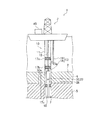
図1は、一実施形態のシステム1を概略的に示す図である。図2は、ライザー管10の先端部10a付近の内部構成を説明する図である。以下、海底の地中内の天然ガスハイドレートを分解して天然ガスを生産するシステム1を例に説明する。
(Specific explanation of gas production system)
FIG. 1 is a diagram schematically showing a system 1 of one embodiment. FIG. 2 is a diagram illustrating an internal configuration in the vicinity of the
システム1は、海上にある掘削船3から海底を経由して地中に延びるライザー管10から地中内の天然ガスハイドレートを分解して生成される天然ガスを地上に取り出すシステムである。
システム1は、ライザー管10と、ポンプ23と、ガス生成ライン12と、液体排出ライン13と、制御装置40と、を主に備える。
The system 1 is a system that takes out natural gas generated by decomposing natural gas hydrate in the ground from a
The system 1 mainly includes a
ライザー管10は、地中内に埋設されるように構成された先端部10aを有する長尺状の管である。ライザー管10は、図1に示す例では、掘削船3から鉛直下方に延び、先端部10aが、海底の坑井7内に埋設されている。坑井7は、掘削により設けられた穴であり、図1に示す例において、海底面2を含む上層4を貫通し、下層に位置するハイドレート層5内で閉塞している。上層4は、例えば、泥を多く含む泥質層である。ハイドレート層5は、例えば、泥と砂を多く含む砂泥互層と呼ばれる層である。ハイドレート層5は、天然ガスハイドレートが砂や泥に取り込まれて存在する、横方向に広がった砂質層を有している。上層4とハイドレート層5との境界は、例えば、海底面下数百メートルの位置にあり、海底面2は、例えば、水深300メートル〜千数百メートルの位置にある。
The
ライザー管10は、管本体11と、スクリーン19(図2参照)と、を備える。
ポンプ23と、ガス生成ライン12と、液体排出ライン13の一部とが、管本体11内に設けられている。
この他に、管本体11内には、ヒータ26が設けられている。
The
A
In addition to this, a
管本体11は、揚収管として機能する部分(管部分)18の後述する孔18aを除いて、内側の空間を水や海水から隔絶する部材である。管本体11には、図1に示す例では、内側の空間を上下に仕切る隔壁17a、17b、及び隔壁17cが設けられている。隔壁17cを通ってライザー管10の先端まで延びる管本体11の部分は、ハイドレート層5から液体内に取り込まれた気液混合物が液体とともに上方に向かって流れる部分18(以降、この部分を、揚収管部分18ともいう)であり、図1に示す例では、隔壁17cから上方の管本体11の部分と比べ、管径が小さい。揚収管部分18は、ハイドレート層5内に位置している。
The
スクリーン19は、揚収管部分18に、ライザー管10の外部に開口した孔18aを覆うように設けられている。孔18aは、ハイドレート層5内の砂質層と接する深さ位置にある揚収管部分18に設けられている。
スクリーン19は、天然ガスハイドレートの分解によって生成した気泡及び水、さらには海水を取り込み、砂や泥を分離除去する部材である。スクリーン19は、気泡、水、海水を通過させるが、砂や泥を通過させない機能を有している。スクリーン19は、例えば、多数の孔を有するシート状又は板状の構造体であって、互いに孔の大きさや形態が異なる複数の構造体から構成される。複数の構造体の組み合わせの具体例として、ジョンソンスクリーン、メッシュ、及びグレーチングが挙げられる。ジョンソンスクリーンは、ジョンソンスクリーン社製の金網状の構造体として周知である。グレーチングは鋼材を格子状に組んだ部材である。ジョンソンスクリーン、メッシュ、グレーチングは、揚収管部分18の側からハイドレート5層の側に向かって、この順に、揚収管部分18に重ねて配置される。
The
The
図2に示すように、揚収管部分18には、スクリーン19を通過した気液混合物を取り込むための複数の孔18aが深さ方向に沿って設けられている。孔18aは、揚収管部分18の壁部を貫通し、揚収管部分18の外部に開口している。ライザー管10が孔18aを備えることで、坑底圧を用いて天然ガスハイドレートに作用する圧力を低減し、これによって、気液混合物をライザー管10内に取り込むことができる。
坑底圧とは、後述する液面Sの下方の液体によって、ライザー管10の下端が受ける水頭圧によって定まる圧力である。ライザー管10の下端は、坑井7の穴底(坑底)と略同じ高さに位置している。ここで、先端部10aは、ライザー管10のうち孔18aの設けられる部分を含む。
ライザー管10内の液体には、天然ガスハイドレートから分解して生成された気液混合物が取り込まれるほか、孔18aを通って進入した水や海水が取り込まれる。気液混合物は気泡を含むので、ライザー管10内の液体には気泡が混在している。水や海水は、ハイドレート層5に含まれる水や海水、ハイドレート層5と接する他の地層に含まれる水や海水を起源としている。
As shown in FIG. 2, the
The bottom pressure is a pressure determined by the head pressure received by the lower end of the
In the liquid in the
ライザー管10は、揚収管部分18の先端部、詳細にはライザー管10の下端に設けられた、坑底圧を測定する圧力計31を、さらに有している。圧力計31は、制御装置40に接続されており、坑底圧の計測信号を制御装置40に向けて出力する。
The
図2に示すように、ポンプ23、及びヒータ26は、隔壁17b、17cによって仕切られたライザー管10の空間15b内に設けられている。空間15bを囲むライザー管10の部分は、気液分離槽20として機能する。空間15b内には、図2に示す例において、液体の液面Sの上方に、気液分離槽20において液体から分離されたガスが流入する気相空間Gが形成される。
As shown in FIG. 2, the
気液分離槽20では、揚収管部分18内で液体に取り込まれる気液混合物中の気泡の少なくとも一部が分離される。分離された気泡内のガスは、生産されるガスである。気液分離槽20内には、液体排出ライン13を構成する、後述する液体輸送管14が配置される。気液分離槽20に関しては、後で詳細に説明する。
In the gas-
液体輸送管14内には、ポンプ23が設けられている。ポンプ23は、ライザー管10内の液体を吸い上げてライザー管10の外部に排出する。具体的に、ポンプ23は、空間15b内の液体を液体輸送管14内に引き込んでライザー管10から排出させる。図2に示す例のポンプ23は、モータ24と、モータ24によって駆動されるスクリュー25と、を有するオーガポンプである。スクリュー25は、鉛直方向に延びる軸と、軸の周りを螺旋状に延びる羽根と、を有しており、液体輸送管14内の液体を撹拌しながら上方に送る機能を有する。モータ24は、掘削船3の制御装置40に電気的に接続されている。モータ24は、制御装置40から出力された信号を受けて、設定された周波数あるいは調整された周波数で駆動するよう制御される。モータ24は、液体輸送管14内に、液体の流路となる隙間を形成するよう、液体輸送管14内に配置されている。なお、システム1の運転中、ライザー管10には孔18aを通って海水あるいは水が流入し続けることから、通常、ポンプ23は稼働した状態に維持される。
A
ヒータ26は、空間15b内に流れ込んだ液体を加熱する装置である。ヒータ26は、制御装置40に接続されている。天然ガスハイドレートの分解反応は吸熱反応であるため、液体に取り込まれた気液混合物の温度が低下して天然ガスハイドレートが再生成し、例えば、液体輸送管14の下端を閉塞させる場合がある。ヒータ26は、システム1の運転中に継続してあるいは断続的に、液体を加熱して、天然ガスハイドレートの再生成を抑制する。また、天然ガスハイドレートが再生成したと判断された場合に、制御装置40から出力された信号を受けて駆動するよう制御され、液体を加熱することで、再生成した天然ガスハイドレートを加熱し、分解させる。
The
ガス生成ライン12は、液面Sに浮上した気泡から生成され、気相空間Gに流入したガスを、生産する天然ガスとしてライザー管10内から取り出す、ガスの流路を構成する。具体的に、ガス生成ライン12は、気相空間G内のガスを、生産する天然ガスとして掘削船3まで運ぶ管からなる。ガス生成ライン12は、管本体11内に、液面Sの上方に配置されており、ガス生成ライン12の下端は、気相空間Gに接続されている。
ガス生成ライン12の先端部には、ガスの圧力を調節する弁が設けられている。また、ガス生成ライン12の先端は、例えば、掘削船3あるいは他の船舶に備え付けられた貯蔵タンク(図示せず)に接続されている。貯蔵タンクに貯蔵された天然ガスは、適宜、液化され、掘削船3あるいは他の船舶で海上を輸送される。
The
A valve for adjusting the pressure of the gas is provided at the tip of the
液体排出ライン13は、管本体11内で天然ガスと分離した液体を掘削船3まで運ぶ、液体の流路を構成する。
液体排出ライン13は、図1に示す例において、気液分離槽20から空間15aまで延びる液体輸送管14と、管本体11から分岐して、空間15aから掘削船3まで延びる管16と、を有している。空間15aは、隔壁17a,17bで仕切られた空間である。
排出された液体は、回収され、例えば貯水される。
The liquid discharge line 13 constitutes a liquid flow path that carries the liquid separated from the natural gas in the
In the example shown in FIG. 1, the liquid discharge line 13 includes a
The discharged liquid is collected and stored, for example, in water.
ライザー管10の先端部10aには、ライザー管10の先端部10aにおける圧力(坑底圧)を計測する圧力計31が設けられている。圧力計31は、制御装置40に接続されており、先端部10aにおける圧力(坑底圧)の計測結果の情報が、制御装置40に送信される。先端部10aにおける圧力は、液体の液面Sの位置及び気相空間Gの圧力によって定まる。
The
制御装置40は、坑底圧に応じて、天然ガスハイドレートに作用する圧力を制御するよう構成される。制御装置40は、CPU、メモリ等を含むコンピュータで構成される。制御装置40は、図1に示す例において、掘削船3に設けられている。
The
坑底圧は、圧力計31から送信される計測結果の情報から取得される。制御装置40は、一定の時間間隔で、坑底圧が目標圧力の範囲にあるか否かを判定する。この判定において、坑底圧が目標圧力の範囲内にあれば、ガスハイドレートに作用する圧力を維持する制御を行う。具体的には、ポンプ23の回転数を維持する。一方、坑底圧が目標圧力の範囲を超えて高くなっている場合、天然ガスハイドレートの分解の速度が所定の範囲にないので、坑底圧が低くなるよう制御を行う。具体的には、ポンプ23の回転数を上げる。また、坑底圧が目標圧力の範囲より低くなっている場合、天然ガスハイドレートの分解の速度が所定の範囲にないので、坑底圧が高くなるよう制御を行う。具体的には、ポンプ23の回転数を下げる。
The bottom pressure is acquired from the measurement result information transmitted from the
システム1は、例えば、ライザー管10となる資材、及び、ポンプ23、ガス生成ライン12、液体排出ライン13、制御装置40を掘削船3に積み、海上の所定の位置まで輸送して組み立てられる。坑井7は、システム1を組み立てる前に予め掘削される。
The system 1 is assembled by loading, for example, a material to be a
システム1は、掘削船3の代わりに、固定式又は浮遊式の洋上プラットフォームを備えてもよい。この場合、洋上プラットフォームと陸地とを接続し、洋上プラットフォームから陸地に天然ガスを輸送するパイプラインを備えることが好ましい。 The system 1 may include a fixed or floating offshore platform instead of the drillship 3. In this case, it is preferable to provide a pipeline that connects the offshore platform and the land and transports natural gas from the offshore platform to the land.
(気液分離槽)
次に、図3を参照しながら、気液分離槽20について説明する。
図3は、気液分離槽20を説明する図であり、気液分離槽20を、図2の側方(左方)から見て示す図である。図3には、揚収管部分18の内部構成が示されている。なお、図3において、気液分離槽20は、図2に示した気液分離槽20と異なる寸法で、簡略化して示されている。
(Gas-liquid separation tank)
Next, the gas-
FIG. 3 is a diagram for explaining the gas-
ライザー管10の空間15bは、ライザー管10の管本体11の内壁に囲まれた空間である。なお、図3に示す例において、空間15bは、鉛直方向に延びる略円柱状の空間である。空間15bには、気液混合物が取り込まれた液体が供給される。
図3に示す例において、揚収管部分18は、隔壁17cの上方に延びており、揚収管部分18の上端は空間15b内に位置している。なお、図2において、隔壁17cから上方に延びる揚収管部分18の部分の図示は省略されている。
The
In the example shown in FIG. 3, the
システム1において、揚収管部分18は、液体が、上方に向かって延びる直線の周りを旋回しながら上方に向かって流れるよう構成されている。上方に向かって延びる直線とは、鉛直方向に延びる仮想直線であり、図3に示す例において揚収管部分18の後述する軸51を通る直線である。具体的に、図3に示す例の揚収管部分18は、上方に向かって直線状に延び、揚収管部分18の内壁に沿って液体が螺旋状に流れる流路を形成するよう構成されている。
図3に示す例の揚収管部分18は、管本体の内側に、流路形成部材50が設けられている。流路形成部材50は、鉛直方向に延びる軸51と、軸51に設けられた羽根52と、を有し、スクリュー形状を有している。羽根52は、軸51から径方向外側に突出し、かつ、軸51の周りを螺旋状に延びている。羽根52は、揚収管部分18の内壁に隙間なく固定されている。このような流路形成部材50によって、揚収管部分18内には、揚収管部分18の内壁に沿って液体が螺旋状に流れる流路が形成されている。
In the system 1, the
In the
気泡を含んだ液体は、この揚収管部分18内を、軸51を旋回中心として、軸51の周りを旋回しながら上方に向かって流れる。このとき、液体には、旋回中心から外側に向かう遠心力が作用する。これにより、液体と気体の比重差によって、液体は軸51から遠ざかる側(外側)に移動し、気泡は軸51に近づく側(内側)に集められる。内側に集められた気泡は、互いに接触する頻度が高いので、一部の気泡同士は一体となって(合泡して)、大きくなる。大きくなった気泡は、揚収管部分18から液体が空間15b内に排出された後に、空間15b内の液面に浮上しやすく、液体から分離されやすい。このように、システム1では、気体と液体とを分離する能力(気液分離性能)が向上しており、ポンプ23に導入される液体への気体の混入が抑制される。これにより、ポンプ23による液体の排出量が安定し、ライザー管10の先端部10aにおける圧力(坑底圧)は変動し難くなる。このため、ガスハイドレートに作用する圧力も変動し難くなり、ガスの生産を安定して行うことができる。
The liquid containing air bubbles flows upward in the
特に、ガスハイドレートの分解の程度が大きくなった場合に、高圧の海水中に発生する微細気泡は、浮上する力が弱く、液体から分離され難い。しかし、微細気泡を多数含んだ液体が揚収管部分18に流れ込んでも、上述したように気液分離性能が向上していることで、ポンプ23に導入される液体への気体の混入が抑制される。
In particular, when the degree of decomposition of gas hydrate becomes large, the fine bubbles generated in high-pressure seawater have a weak floating force and are difficult to be separated from the liquid. However, even if a liquid containing a large number of fine bubbles flows into the
また、システム1の気液分離性能が向上しているため、気体を含んだ液体の滞留時間を増やすために空間15bのサイズアップを行う必要がない。気液分離を行う空間は、通常、海底の坑井内に埋設されたライザー管の部分に配置されているため、サイズアップによって気液分離性能を上げることは困難である。
Further, since the gas-liquid separation performance of the system 1 is improved, it is not necessary to increase the size of the
また、遠心力を利用して気液分離を行うため、従来、ライザー管10内での気液分離に用いられていた遠心分離器を、システム1において省略することができる。なお、従来の遠心分離器は、例えば、液体輸送管内に配置され、遠心力を利用して液体輸送管内で集めた気泡を液体輸送管の外側に放出するよう構成される。
Further, since the gas-liquid separation is performed by using the centrifugal force, the centrifuge conventionally used for the gas-liquid separation in the
一実施形態によれば、揚収管部分18は、図4に示されるように、流路に対して揚収管部分18の径方向の内側に、上方に向かって延びる空洞領域54を形成するよう構成されていることが好ましい。図4は、揚収管部分18の変形例を説明する図である。
揚収管部分18は、管本体の内側に、流路形成部55が設けられている。図4に示す例の流路形成部55は、螺旋状の傾斜壁53で構成される。傾斜壁53は、揚収管部分18の内壁から径方向内側に突出し、かつ、揚収管部分18の径方向の中心を通る直線の周りを螺旋状に延びている。図4に示す例において、揚収管部分18の内壁からの傾斜壁53の突出高さは、揚収管部分18の内径の半径よりも短い。このため、傾斜壁53の径方向の内側に、空洞領域54が形成されている。空洞領域54は、上記直線に沿って上方に向かって延びている。
According to one embodiment, the
The
気泡を含んだ液体は、この揚収管部分18内を、揚収管部分18の径方向の中心を通る直線を旋回中心として旋回しながら上方に向かって流れる。この場合も、図3に示した揚収管部分18を流れる場合と同様に、液体に遠心力が作用し、気泡が内側に集められ、一部の気泡は大きくなる。そして、図4に示す例の揚収管部分18では、集められた気泡、及び大きくなった気泡は、空洞領域54を通って、傾斜壁53によって形成される螺旋状の流路を通ることなく、揚収管部分18内を上昇し、空間15b内に排出される。このようにして、気体は液体から速やかに分離する。
一方で、図4に示す例の揚収管部分18では、液体の一部も空洞領域54を通って上昇する。このような液体の量を低減する観点から、傾斜壁53の突出高さHは、例えば、揚収管部分18の内径(径方向に沿った、対向する内壁同士の間隔)の1/4の長さより長いことが好ましく、揚収管部分18の内径の1/3の長さより長いことがより好ましい。
The liquid containing bubbles flows upward in the
On the other hand, in the
揚収管部分18に形成される螺旋状の流路のピッチPは、長すぎると、流路が短くなってしまい、液体に十分に遠心力を作用させることができない。また、螺旋状の流路のピッチPは、短いほど、流路が長くなり、流路を流れる液体の流速が大きくなる。これは、揚収管部分18を通過する液体の流量は、流路の長さに依存しないためである。これらの観点から、螺旋状の流路のピッチPは、揚収管部分18の内径の2倍の長さよりも短いことが好ましい。
一方で、揚収管部分18の螺旋状の流路のピッチPは、短すぎると、流路が長くなりすぎて、摩擦損失が大きくなるため、螺旋状の流路のピッチPは、揚収管部分18の内径の0.5倍の長さよりも長いことが好ましい。
If the pitch P of the spiral flow path formed in the
On the other hand, if the pitch P of the spiral flow path of the
揚収管部分18が、空間15b内に液体を供給する高さ位置は、図3に示されるように、ポンプ23によって液体が吸い上げられる高さ位置よりも高いことが好ましい。具体的には、揚収管部分18の供給口18bの高さ位置は、液体輸送管14の吸込口14aの高さ位置よりも高いことが好ましい。これにより、揚収管部分18から空間15b内に供給された液体は、液体輸送管14内に流れ込むまでに、下方に向かって流れるため、液体と気体にかかる重力を利用して、液体中に残存する気泡の一部をさらに分離することができる。このため、システム1の気液分離性能が増す。
The height position at which the
一実施形態によれば、揚収管部分18は、図5及び図6に示されるように、空間15bをなすライザー管10の内壁に沿って周状に流れる液体の旋回流が形成されるよう、空間15b内に液体を供給することが好ましい。
図5は、気液分離槽の変形例を示す図である。図5において、揚収管部分18は、図3に示した揚収管部分と寸法を異ならせて、簡略化して示されている。図6は、図5の気液分離槽を上面視して示す図である。
図5及び図6に示す例において、揚収管部分18の上端には、揚収管部分18の鉛直方向に延びる部分に対して直交するよう延びる先端部18cが設けられている。先端部18cには、揚収管部分18を流れた液体を空間15b内に供給する供給口18bが設けられている。
ライザー管10の内壁に沿って周状に流れる旋回流は、図6に示す例において、円弧状の矢印で指す方向(円周方向)に流れる。このような旋回流は、揚収管部分18が、図6に示されるように、旋回流の流路の接線方向Tの成分を含む方向に、液体を空間15b内に供給することで形成される。旋回流の流路の接線方向Tは、図6に示す例において、円柱状の空間15bの中心Oを中心とする円の接線方向である。
このような旋回流が形成されると、空間15b内に供給された、気泡を含んだ液体に対して、旋回流の中心Oから外側に向かう遠心力が作用する。これにより、液体と気体の比重差によって、液体は旋回流の中心Oから遠ざかる側(外側)に移動し、気泡は旋回流の中心Oに近づく側(内側)に集められる。内側に集められた気泡の一部は、気泡同士が一体となって、大きくなるため、液面に浮上しやすく、液体から分離されやすい。このため、システム1の気液分離性能は一段と向上する。
According to one embodiment, the
FIG. 5 is a diagram showing a modified example of the gas-liquid separation tank. In FIG. 5, the
In the examples shown in FIGS. 5 and 6, the upper end of the
The swirling flow that flows circumferentially along the inner wall of the
When such a swirling flow is formed, a centrifugal force acting from the center O of the swirling flow to the outside acts on the liquid containing bubbles supplied in the
なお、上記した旋回流をつくる手段は、図5及び図6に示す形態の揚収管部分18に制限されない。
例えば、図3及び図4に示す例の揚収管部分18のように、鉛直方向に延びる部分のみからなる揚収管部分によってもつくることができる。図7に、図3に示した揚収管部分18の先端(供給口18b)を上面視して示す。
揚収管部分18の先端位置で螺旋状の流路が途切れていると、液体は、途切れた位置における流路に沿った方向(図7の矢印Aで指す方向)に排出される。したがって、矢印Aで示す、螺旋状の流路に沿った方向と、上記した旋回流の流れる方向とが一致するように、揚収管部分18の先端を構成し、空間15b内に配置することで、供給口18bから排出された液体によって、空間15b内に旋回流をつくることができる。
The means for creating the swirling flow described above is not limited to the
For example, as in the example of the
When the spiral flow path is interrupted at the tip position of the
また、図5及び図6に示す例のように、揚収管部分18が、鉛直方向に延びる部分と交差した方向に延びる先端部18cを有している場合、先端部18cも、螺旋状の流路が形成されるよう構成されていることが好ましい。この場合、螺旋状の流路は、さらに、供給口18bにおいて、上記説明したように途切れていることが好ましい。このような先端部18cを、液体が、空間15b内で上方かつ中心O側に向かって排出されるよう構成し、配置することで、図8に示すような、螺旋状の流れを伴った旋回流を作ることができる。図8は、気液分離槽20における液体の流れを説明する図であり、旋回流の中心Oを通る空間15bの断面を見たときの液体の流れを示している。
図8に示す例の旋回流は、空間15b内の外側において上昇流が生じ、内側において下降流が生じている。上述したように、空間15b内に旋回流がつくられると、気泡は内側に集められるため、空間15b内の内側で下降流が生じていることで、気泡の滞留時間が長くなり、合泡しやすくなることで、気泡は浮上しやすく、液体からさらに分離しやすくなる。
Further, as in the example shown in FIGS. 5 and 6, when the
In the swirling flow of the example shown in FIG. 8, an upward flow is generated on the outside of the
したがって、一実施形態として、地中内のガスハイドレートを分解してガスを生産する天然ガス生産方法を以下のように実現することができる。
地中内に埋設された先端部10aを有し、先端部10aから上方に延びるライザー管10内の液体によってライザー管10内に生じる先端部10aにおける圧力を用いてライザー管10の外部にある天然ガスハイドレートに作用する圧力を低減させる。
次に、天然ガスハイドレートに作用する、低減された圧力によって天然ガスハイドレートから分解して生成される気泡を含む気液混合物を、ライザー管10の外部に開口した孔18aからライザー管10内の液体に取り込む。
ポンプ23を用いて、ライザー管10内の液体を吸い上げてライザー管10の外部に排出する。
天然ガスを取り出すとき、先端部10aの揚収管部分18を用いて、液体を、上方に向かって延びる直線の周りを旋回しながら上方に向かうように流し、揚収管部分18からライザー管10内に液体を供給し、
排出するステップでは、揚収管部分18からライザー管10内に供給された液体を吸い上げる。
Therefore, as one embodiment, a natural gas production method for producing gas by decomposing gas hydrate in the ground can be realized as follows.
Natural gas outside the
Next, a gas-liquid mixture containing bubbles generated by decomposition from the natural gas hydrate by the reduced pressure acting on the natural gas hydrate is introduced into the
The
When taking out natural gas, the
In the discharge step, the liquid supplied into the
この天然ガス生産方法では、ライザー管内に取り込まれた、気泡を含んだ液体は、先端部の管部分を上方に向かって流れ、ライザー管内に供給され、ポンプによって吸い上げられる。このとき、気泡を含んだ液体は、管部分内を、上方に向かって延びる直線の周りを旋回しながら流れるため、気泡を含んだ液体には遠心力が作用し、液体と気体の比重差によって、液体は直線から遠ざかる側(外側)に移動し、気泡は直線に近づく側(内側)に集められる。内側に集められた気泡の一部は、気泡同士が一体となって(合泡して)、大きくなるため、液面に浮上しやすく、液体から分離されやすい。 In this natural gas production method, the liquid containing air bubbles taken into the riser pipe flows upward through the pipe portion at the tip portion, is supplied into the riser pipe, and is sucked up by a pump. At this time, since the liquid containing bubbles flows in the pipe portion while swirling around a straight line extending upward, a centrifugal force acts on the liquid containing bubbles due to the difference in specific gravity between the liquid and the gas. , The liquid moves away from the straight line (outside), and the bubbles are collected on the side approaching the straight line (inside). Some of the bubbles collected inside are easily separated from the liquid because the bubbles are united (combined) and become large, so that they easily float on the liquid surface.
このように、気体と液体とを分離する能力(気液分離性能)が向上しているため、ポンプに導入される液体への気体の混入が抑制される。この結果、ポンプによる液体の排出量が安定し、ライザー管内の液面の高さが安定し、ライザー管の先端部における圧力(坑底圧)は変動し難くなる。このため、ガスハイドレートに作用する圧力も変動し難くなり、ガスの生産を安定して行うことができる。 In this way, since the ability to separate gas and liquid (gas-liquid separation performance) is improved, the mixing of gas into the liquid introduced into the pump is suppressed. As a result, the amount of liquid discharged by the pump is stable, the height of the liquid level in the riser pipe is stable, and the pressure (pit pressure) at the tip of the riser pipe is less likely to fluctuate. Therefore, the pressure acting on the gas hydrate is less likely to fluctuate, and gas production can be stably performed.
天然ガスを取り出すステップとき、上方に向かって直線状に延びる揚収管部分18を用いて、揚収管部分18の内壁に沿って液体を螺旋状に流すことが好ましい。
When taking out the natural gas, it is preferable to use the
天然ガスを取り出すとき、さらに、ライザー管10の内壁に囲まれた空間内に、内壁に沿って周状に流れる液体の旋回流が形成されるよう、揚収管部分18から空間15b内に液体を供給することが好ましい。このような旋回流が形成されると、空間15b内に供給された、気泡を含んだ液体に対して、旋回流の中心から外側に向かう遠心力が作用する。これにより、液体と気体の比重差によって、液体は旋回流の中心から遠ざかる側(外側)に移動し、気泡は旋回流の中心に近づく側(内側)に集められる。内側に集められた気泡の一部は、気泡同士が一体となって、大きくなるため、液面に浮上しやすく、液体から分離されやすい。このため、気液分離性能は一段と向上する。
When the natural gas is taken out, the liquid is further formed from the
以上、本発明のガス生産システム及びガス生産方法について詳細に説明したが、本発明は上記実施形態に限定されず、本発明の主旨を逸脱しない範囲において、種々の改良や変更をしてもよいのはもちろんである。 Although the gas production system and the gas production method of the present invention have been described in detail above, the present invention is not limited to the above embodiment, and various improvements and changes may be made without departing from the gist of the present invention. Of course.
1 ガス生産システム
2 海底面
3 掘削船
4 上層
5 ハイドレート層
7 坑井
10 ライザー管
10a 先端部
11 管本体
12 ガス生成ライン
13 液体排出ライン
14 液体輸送管
15a 空間
16 管
17a,17b,17c 隔壁
18 揚収管部分
18c 揚収管部分の先端部
20 気液分離槽
23 ポンプ
24 モータ
25 スクリュー
26 ヒータ
31 圧力計
40 制御装置
50 流路形成部材
51 軸
52 羽根
53 傾斜壁
54 空洞領域
55 流路形成部
1
Claims (5)
地中内に埋設されるように構成された先端部を有する長尺状の管であって、前記先端部から上方に延びる前記管内の液体によって生じる圧力を用いて前記管の外部にあるガスハイドレートに作用する圧力を低減することにより、前記ガスハイドレートから分解して生成される気泡を含む気液混合物を前記管内の前記液体に取り込むように、前記先端部に設けられ前記管の外部に開口した孔を備えるライザー管と、
前記ライザー管内の前記液体を吸い上げて前記ライザー管の外部に排出するポンプと、を備え、
前記先端部は、前記液体が、上方に向かって延びる直線の周りを旋回しながら上方に向かって流れるよう構成された揚収管を有し、
前記ポンプは、前記揚収管から前記ライザー管内に供給された前記液体を吸い上げ、
前記揚収管は、前記孔を有し、前記液体が供給される前記ライザー管の部分よりも細く、上方に向かって直線状に延び、前記揚収管の内壁に沿って前記液体が螺旋状に流れる流路を形成するよう構成され、
前記揚収管が、前記ライザー管内に前記液体を供給する高さ位置は、前記ポンプによって前記液体が吸い上げられる高さ位置よりも高い、ことを特徴とするガス生産システム。 A system that produces gas by decomposing gas hydrate in the ground.
A long tube having a tip configured to be buried in the ground, a gas hide outside the tube using the pressure generated by the liquid in the tube extending upward from the tip. By reducing the pressure acting on the rate, a gas-liquid mixture containing bubbles generated by decomposition from the gas hydrate is provided at the tip of the pipe and outside the pipe so as to be taken into the liquid in the pipe. A riser tube with an open hole and
A pump that sucks up the liquid in the riser pipe and discharges it to the outside of the riser pipe is provided.
The tip has a lift tube configured for the liquid to flow upward while swirling around a straight line extending upward.
The pump on up suck the liquid supplied to the riser pipe from the AgeOsamukan,
The lift pipe has the holes, is thinner than the portion of the riser pipe to which the liquid is supplied, extends linearly upward, and the liquid spirals along the inner wall of the lift pipe. It is configured to form a flow path to
A gas production system characterized in that the height position at which the lift pipe supplies the liquid into the riser pipe is higher than the height position at which the liquid is sucked up by the pump .
地中内に埋設されるように構成された先端部を有する長尺状の管であって、前記先端部から上方に延びる前記管内の液体によって生じる圧力を用いて前記管の外部にあるガスハイドレートに作用する圧力を低減することにより、前記ガスハイドレートから分解して生成される気泡を含む気液混合物を前記管内の前記液体に取り込むように、前記先端部に設けられ前記管の外部に開口した孔を備えるライザー管と、A long tube having a tip configured to be buried in the ground, a gas hide outside the tube using the pressure generated by the liquid in the tube extending upward from the tip. By reducing the pressure acting on the rate, a gas-liquid mixture containing bubbles generated by decomposition from the gas hydrate is provided at the tip of the pipe and outside the pipe so as to be taken into the liquid in the pipe. A riser tube with an open hole and
前記ライザー管内の前記液体を吸い上げて前記ライザー管の外部に排出するポンプと、を備え、A pump that sucks up the liquid in the riser pipe and discharges it to the outside of the riser pipe is provided.
前記先端部は、前記孔を有し、前記液体が供給される前記ライザー管の部分よりも細い揚収管であって、上方に向かって直線状に延び、前記液体が、上方に向かって延びる直線の周りを旋回しながら上方に向かって流れるよう構成された揚収管を有し、The tip portion has the hole and is thinner than the portion of the riser pipe to which the liquid is supplied, and extends linearly upward, and the liquid extends upward. It has a lift pipe that is configured to flow upward while swirling around a straight line.
前記揚収管には、前記揚収管の内壁に沿って前記液体が螺旋状に流れる流路が形成され、前記流路に対して前記揚収管の径方向の内側に、上方に向かって延びる空洞領域が形成されるよう、前記揚収管の前記内壁から径方向内側に突出し、前記揚収管の径方向の中心を通る直線の周りを螺旋状に延びる傾斜壁が設けられ、The lift pipe is formed with a flow path through which the liquid flows spirally along the inner wall of the lift pipe, and is upward inward in the radial direction of the lift pipe with respect to the flow path. An inclined wall is provided that protrudes radially inward from the inner wall of the lift pipe and spirally extends around a straight line passing through the radial center of the lift pipe so as to form an extending cavity region.
前記傾斜壁の前記内壁からの突出高さは、前記揚収管の内径の1/4の長さより長く、The height of the inclined wall protruding from the inner wall is longer than 1/4 of the inner diameter of the lift pipe.
前記ポンプは、前記揚収管から前記ライザー管内に供給された前記液体を吸い上げる、ことを特徴とするガス生産システム。The gas production system, wherein the pump sucks up the liquid supplied from the pickup pipe into the riser pipe.
前記揚収管は、前記ライザー管の前記内壁に沿って周状に流れる前記液体の旋回流が前記空間内に形成されるよう、前記空間内に前記液体を供給する、請求項1又は2に記載のガス生産システム。 The riser tube includes a space surrounded by an inner wall of the riser tube.
Claim 1 or 2 , wherein the lift pipe supplies the liquid into the space so that a swirling flow of the liquid flowing around the inner wall of the riser pipe is formed in the space. The gas production system described.
地中内に埋設された先端部を有し、前記先端部から上方に延びるライザー管内の液体によって生じる圧力を用いて前記管の外部にあるガスハイドレートに作用する圧力を低減させるステップと、
前記ガスハイドレートに作用する、低減された圧力によって前記ガスハイドレートから分解して生成される気泡を含む気液混合物を、前記ライザー管の外部に開口した孔から前記ライザー管内の前記液体に取り込み、前記気泡からガスを取り出すステップと、
ポンプを用いて、前記ライザー管内の前記液体を吸い上げて前記ライザー管の外部に排出するステップと、を備え、
前記ガスを取り出すステップでは、前記孔を有し、前記液体が供給される前記ライザー管の部分よりも細い揚収管であって、上方に向かって直線状に延び、上方に向かって延びる直線の周りを旋回しながら上方に向かって前記液体が流れるよう構成された前記先端部の揚収管を用いて、前記液体を、上方に向かって延びる直線の周りを旋回しながら上方に向かうように流し、前記揚収管から前記ライザー管内に前記液体を供給し、
前記排出するステップでは、前記揚収管から前記ライザー管内に供給された前記液体を吸い上げ、
前記揚収管には、前記揚収管の内壁に沿って前記液体が螺旋状に流れる流路が形成され、前記流路に対して前記揚収管の径方向の内側に、上方に向かって延びる空洞領域が形成されるよう、前記揚収管の前記内壁から径方向内側に突出し、前記揚収管の径方向の中心を通る直線の周りを螺旋状に延びる傾斜壁が設けられ、
前記傾斜壁の前記内壁からの突出高さは、前記揚収管の内径の1/4の長さより長い、ことを特徴とするガス生産方法。 It is a method of producing gas by decomposing gas hydrate in the ground.
A step of reducing the pressure acting on the gas hydrate outside the tube by using the pressure generated by the liquid in the riser tube which has a tip buried in the ground and extends upward from the tip.
A gas-liquid mixture containing bubbles generated from the gas hydrate decomposed by the reduced pressure acting on the gas hydrate is taken into the liquid in the riser tube through a hole opened outside the riser tube. , The step of extracting gas from the bubbles,
A step of sucking up the liquid in the riser tube and discharging it to the outside of the riser tube by using a pump is provided.
In the step of taking out the gas, a lift pipe having the holes and thinner than the portion of the riser pipe to which the liquid is supplied, which extends linearly upward and extends upward. Using the lift pipe at the tip, which is configured to allow the liquid to flow upward while swirling around, the liquid is allowed to flow upward while swirling around a straight line extending upward. , The liquid is supplied from the lift pipe into the riser pipe.
Wherein in the step of discharging, on up suck the liquid supplied to the riser pipe from the AgeOsamukan,
The lift pipe is formed with a flow path through which the liquid flows spirally along the inner wall of the lift pipe, and is upward inward in the radial direction of the lift pipe with respect to the flow path. An inclined wall is provided that protrudes radially inward from the inner wall of the lift pipe and spirally extends around a straight line passing through the radial center of the lift pipe so as to form an extending cavity region.
A gas production method characterized in that the height of protrusion of the inclined wall from the inner wall is longer than the length of 1/4 of the inner diameter of the lift pipe .
Priority Applications (1)
| Application Number | Priority Date | Filing Date | Title |
|---|---|---|---|
| JP2018044237A JP6799734B2 (en) | 2018-03-12 | 2018-03-12 | Gas production system and gas production method |
Applications Claiming Priority (1)
| Application Number | Priority Date | Filing Date | Title |
|---|---|---|---|
| JP2018044237A JP6799734B2 (en) | 2018-03-12 | 2018-03-12 | Gas production system and gas production method |
Publications (2)
| Publication Number | Publication Date |
|---|---|
| JP2019157465A JP2019157465A (en) | 2019-09-19 |
| JP6799734B2 true JP6799734B2 (en) | 2020-12-16 |
Family
ID=67995846
Family Applications (1)
| Application Number | Title | Priority Date | Filing Date |
|---|---|---|---|
| JP2018044237A Active JP6799734B2 (en) | 2018-03-12 | 2018-03-12 | Gas production system and gas production method |
Country Status (1)
| Country | Link |
|---|---|
| JP (1) | JP6799734B2 (en) |
Family Cites Families (12)
| Publication number | Priority date | Publication date | Assignee | Title |
|---|---|---|---|---|
| DE19620591B4 (en) * | 1996-05-22 | 2004-08-26 | Fresenius Medical Care Deutschland Gmbh | Device for removing gases from liquids |
| JP3047546U (en) * | 1997-09-26 | 1998-04-14 | 株式会社シイエヌケイ | Coolant cleaning device with defoaming mechanism |
| JPH11114453A (en) * | 1997-10-13 | 1999-04-27 | Kubota Corp | Gas-liquid separator |
| DE69908419T2 (en) * | 1998-12-31 | 2004-03-18 | Shell Internationale Research Maatschappij B.V. | METHOD FOR REMOVING CONDENSIBLE COMPONENTS FROM A NATURAL GAS FLOW, AT A HOLE HOLE HEAD, DOWNWARD OF THE HOLE HOLE HEAD THROTTLE VALVE |
| JP2008051344A (en) * | 2006-08-22 | 2008-03-06 | Daikin Ind Ltd | Gas-liquid separator and refrigeration apparatus equipped with the gas-liquid separator |
| JP5523737B2 (en) * | 2009-05-08 | 2014-06-18 | 一般財団法人電力中央研究所 | Methane hydrate mining method using carbon dioxide |
| JP5439026B2 (en) * | 2009-05-11 | 2014-03-12 | 株式会社神戸製鋼所 | Gas-liquid separator |
| JP5674755B2 (en) * | 2012-12-26 | 2015-02-25 | 株式会社ミンガス | Gas separator |
| JP5278863B1 (en) * | 2013-01-11 | 2013-09-04 | 満晴 奥野 | Methane gas production equipment from methane hydrate |
| JP2016166476A (en) * | 2015-03-10 | 2016-09-15 | 三井造船株式会社 | Riser pipe |
| NO340973B1 (en) * | 2015-12-22 | 2017-07-31 | Aker Solutions As | Subsea methane hydrate production |
| NO344641B1 (en) * | 2016-07-06 | 2020-02-17 | Aker Solutions As | Subsea methane production assembly |
-
2018
- 2018-03-12 JP JP2018044237A patent/JP6799734B2/en active Active
Also Published As
| Publication number | Publication date |
|---|---|
| JP2019157465A (en) | 2019-09-19 |
Similar Documents
| Publication | Publication Date | Title |
|---|---|---|
| TWI804548B (en) | Floating liquid intake | |
| US10273772B2 (en) | Drilling debris separator | |
| JP5294110B2 (en) | Methane gas production method from methane hydrate and apparatus for producing methane gas from methane hydrate | |
| JP2015031097A (en) | Methane hydrate collection system, and methane hydrate collection method | |
| JP6236347B2 (en) | Separation apparatus and separation method | |
| US10934829B2 (en) | Systems, apparatuses, and methods for downhole water separation | |
| JP6799733B2 (en) | Gas production system and gas production method | |
| JP6799734B2 (en) | Gas production system and gas production method | |
| US8397821B2 (en) | Caisson two-phase emulsion reducer | |
| JP6736808B2 (en) | Gas production system and gas production method | |
| JP6735978B2 (en) | Gas production system and gas production method | |
| JP6792752B2 (en) | Gas production system and gas production method | |
| JP6788770B2 (en) | Gas production system and gas production method | |
| JP6736809B2 (en) | Gas production system and gas production method | |
| US11241639B2 (en) | Gas-liquid separator, hydrocarbon extractor, and related separation method | |
| JP6792749B1 (en) | Gas-liquid multiphase flow flow mode evaluation device, flow mode evaluation method, and gas production system | |
| JP6735979B2 (en) | Gas production system and gas production method | |
| CN102711941A (en) | Subsea separation systems | |
| JP2010000424A (en) | Solid-liquid separator | |
| JP6735980B2 (en) | Gas production system | |
| JP6396172B2 (en) | Hydrate collection device and collection method | |
| JP2019143309A (en) | Gas hydrate digging equipment and digging method | |
| WO2016036256A1 (en) | A tool and a method for aiding transport of a first well fluid |
Legal Events
| Date | Code | Title | Description |
|---|---|---|---|
| A621 | Written request for application examination |
Free format text: JAPANESE INTERMEDIATE CODE: A621 Effective date: 20200204 |
|
| A871 | Explanation of circumstances concerning accelerated examination |
Free format text: JAPANESE INTERMEDIATE CODE: A871 Effective date: 20200204 |
|
| A977 | Report on retrieval |
Free format text: JAPANESE INTERMEDIATE CODE: A971007 Effective date: 20200423 |
|
| A975 | Report on accelerated examination |
Free format text: JAPANESE INTERMEDIATE CODE: A971005 Effective date: 20200512 |
|
| A131 | Notification of reasons for refusal |
Free format text: JAPANESE INTERMEDIATE CODE: A131 Effective date: 20200519 |
|
| A521 | Request for written amendment filed |
Free format text: JAPANESE INTERMEDIATE CODE: A523 Effective date: 20200707 |
|
| TRDD | Decision of grant or rejection written | ||
| A01 | Written decision to grant a patent or to grant a registration (utility model) |
Free format text: JAPANESE INTERMEDIATE CODE: A01 Effective date: 20200908 |
|
| A711 | Notification of change in applicant |
Free format text: JAPANESE INTERMEDIATE CODE: A711 Effective date: 20200916 |
|
| A61 | First payment of annual fees (during grant procedure) |
Free format text: JAPANESE INTERMEDIATE CODE: A61 Effective date: 20200929 |
|
| A521 | Request for written amendment filed |
Free format text: JAPANESE INTERMEDIATE CODE: A821 Effective date: 20200916 |
|
| R150 | Certificate of patent or registration of utility model |
Ref document number: 6799734 Country of ref document: JP Free format text: JAPANESE INTERMEDIATE CODE: R150 |
|
| R250 | Receipt of annual fees |
Free format text: JAPANESE INTERMEDIATE CODE: R250 |
|
| R250 | Receipt of annual fees |
Free format text: JAPANESE INTERMEDIATE CODE: R250 |