JP6760665B2 - Portable beverage bottle - Google Patents
Portable beverage bottle Download PDFInfo
- Publication number
- JP6760665B2 JP6760665B2 JP2018215558A JP2018215558A JP6760665B2 JP 6760665 B2 JP6760665 B2 JP 6760665B2 JP 2018215558 A JP2018215558 A JP 2018215558A JP 2018215558 A JP2018215558 A JP 2018215558A JP 6760665 B2 JP6760665 B2 JP 6760665B2
- Authority
- JP
- Japan
- Prior art keywords
- lock
- lock member
- locking
- cap
- lid
- Prior art date
- Legal status (The legal status is an assumption and is not a legal conclusion. Google has not performed a legal analysis and makes no representation as to the accuracy of the status listed.)
- Expired - Fee Related
Links
Images


Landscapes
- Closures For Containers (AREA)
Description
本発明は、携帯用飲料ボトルに関する。 The present invention relates to a portable beverage bottle.
従来の携帯用飲料ボトルは、ボトル本体の開口部に取着する蓋部材と、蓋部材に揺動自在に枢着されると共に蓋部材の口部を施蓋するためのキャップ部材と、を備え、さらに、蓋部材に枢着されキャップ部材を閉状態に保持する第1のロックを行う第1ロック部材と、第1ロック部材にて閉状態に保持されたキャップ部材を起立状姿勢で係止して第2のロックを行う門型の第2ロック部材と、を備えた携帯用飲料ボトルが公知である(例えば、特許文献1参照)。 A conventional portable beverage bottle includes a lid member that is attached to the opening of the bottle body, and a cap member that is swingably pivotally attached to the lid member and that covers the mouth of the lid member. Further, the first lock member that is pivotally attached to the lid member and holds the cap member in the closed state and the cap member that is held in the closed state by the first lock member are locked in an upright posture. A portable beverage bottle provided with a gate-shaped second locking member for performing the second locking is known (see, for example, Patent Document 1).
しかし、第1ロック部材と第2ロック部材とで二重ロックされているキャップ部材を開状態にする際に、先ず、第2ロック部材を、起立状姿勢から垂下状姿勢に揺動操作して、第2のロック(第2ロック部材とキャップ部材との係合)を解除し、次に、第1ロック部材の下部を、使用者の指で押圧して、第1のロック(第1ロック部材とキャップ部材との係合)を解除するため、操作が煩わしいといった問題があった。 However, when opening the cap member that is double-locked by the first lock member and the second lock member, first, the second lock member is swung from an upright position to a hanging position. , The second lock (engagement between the second lock member and the cap member) is released, and then the lower part of the first lock member is pressed with the user's finger to press the first lock (first lock). There is a problem that the operation is troublesome because the engagement between the member and the cap member) is released.
そこで、本発明は、第1のロックと第2のロックを行える二重ロック構造でありながら、キャップ部材を容易に素早く開くことが可能な使い勝手の良い携帯用飲料ボトルの提供を目的とする。 Therefore, an object of the present invention is to provide an easy-to-use portable beverage bottle that can open the cap member easily and quickly while having a double lock structure capable of performing the first lock and the second lock.
本発明の携帯用飲料ボトルは、ボトル本体を施蓋するキャップ部材を閉状態に保持して第1のロックを行う第1ロック部材と、上記第1ロック部材にて閉状態に保持された上記キャップ部材を起立状姿勢で係止して第2のロックを行う門型の第2ロック部材と、を備えた携帯用飲料ボトルに於て、上記第2ロック部材を上記起立状姿勢から下方へ揺動して第2のロックを解除すると共に、下方へ揺動して垂下状姿勢となった上記第2ロック部材にて上記第1ロック部材を押圧して第1のロックを解除するように構成したものである。 In the portable beverage bottle of the present invention, the first lock member that holds the cap member that covers the bottle body in the closed state to perform the first lock, and the first lock member that is held in the closed state by the first lock member. In a portable beverage bottle provided with a gate-shaped second lock member that locks the cap member in an upright position to perform a second lock, the second lock member is moved downward from the upright position. The first lock member is pressed by the second lock member which swings downward to release the second lock and the second lock member swings downward to release the first lock. It is configured.
また、有底筒状のボトル本体と、該ボトル本体に施蓋状に取着されると共に飲料吐出用の口部を有する蓋部材と、上記蓋部材に揺動自在に枢着されると共に上記口部を施蓋するためのキャップ部材と、上記蓋部材にシーソー状に揺動自在に枢着され上記キャップ部材を閉状態に保持して第1のロックを行う第1係止部を上部に有すると共に下部に押圧操作される被押圧部を有する第1ロック部材と、上記蓋部材に起立状姿勢と垂下状姿勢とに揺動切換自在に枢着され上記第1ロック部材にて閉状態に保持された上記キャップ部材を起立状姿勢で係止して第2のロックを行う門型の第2ロック部材と、を備えた携帯用飲料ボトルであって、上記第2ロック部材は、上記第1ロック部材の両側に配設される一対の柱部の先端部を連結する連結部に、上記起立状姿勢で閉状態の上記キャップ部材に係止する第2係止部を有すると共に、上記垂下状姿勢で上記第1ロック部材の上記被押圧部を押圧する押圧部を有し、上記第2ロック部材を上記起立状姿勢から下方へ揺動して第2のロックを解除すると共に、下方へ揺動して垂下状姿勢となった上記第2ロック部材の上記押圧部にて上記第1ロック部材の上記被押圧部を押圧して第1のロックを解除するように構成したものである。 Further, a bottomed tubular bottle body, a lid member which is attached to the bottle body like a lid and has a mouth portion for discharging a beverage, and a lid member which is swingably pivotally attached to the lid member and described above. A cap member for covering the mouth portion and a first locking portion that is swingably pivotally attached to the lid member in a seesaw shape to hold the cap member in a closed state and perform a first lock are on the upper part. A first lock member having a pressed portion that is held and pressed at the bottom, and a lid member that is pivotally attached to the lid member in an upright position and a hanging position so as to be swingably switchable, and closed by the first lock member. A portable beverage bottle comprising a gate-shaped second lock member that locks the held cap member in an upright position to perform a second lock, wherein the second lock member is the first lock member. 1 The connecting portion connecting the tip portions of the pair of pillar portions arranged on both sides of the locking member has a second locking portion for locking to the cap member in the closed state in the upright posture, and the hanging portion. It has a pressing portion that presses the pressed portion of the first locking member in a state posture, and swings the second locking member downward from the standing posture to release the second lock and downward. The first lock is released by pressing the pressed portion of the first lock member with the pressing portion of the second lock member that swings and becomes a hanging posture.
また、ゴム製の滑り止め用のリング部材を上記蓋部材に外嵌状に取着し、上記第1ロック部材の下部を前方へ常時弾発付勢するための戻し用弾発付勢部を、上記リング部材の一部をもって構成したものである。
また、上記第1ロック部材は、上下中間部が水平状の第1枢着軸心廻りに揺動自在に枢着され、上記第2ロック部材は、水平状の第2枢着軸心廻りに揺動自在に枢着され、上記第2枢着軸心を、上記第1枢着軸心よりも上位置に配設したものである。
Further, a rubber anti-slip ring member is attached to the lid member in an outer fit shape, and a return bullet urging portion for constantly urging the lower portion of the first lock member forward is provided. , It is composed of a part of the above ring member.
Further, the first lock member is pivotally attached to the upper and lower intermediate portions around the horizontal first pivot axis center, and the second lock member is pivotally attached around the horizontal second pivot axis center. It is oscillatingly pivotally attached, and the second pivotal axis is arranged at a position higher than the first pivotal axis.
本発明によれば、第2ロック部材とキャップ部材との係合を解除する操作から連続的に(流れるように)、第1ロック部材とキャップ部材との係合を解除でき、キャップ部材を素早く開くことができる。第1のロックと第2のロックを行える2重ロック構造でありながら直観的に、かつ、容易に開操作できて、使い勝手が良い。 According to the present invention, the engagement between the first lock member and the cap member can be disengaged continuously (flowing) from the operation of disengaging the cap member with the second lock member, and the cap member can be quickly disengaged. Can be opened. Although it has a double lock structure that can perform the first lock and the second lock, it can be opened intuitively and easily, and is easy to use.
以下、図示の実施形態に基づき本発明を詳説する。
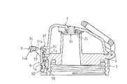
本発明に係る携帯用飲料ボトルは、図1乃至図3に示すように、有底筒状のボトル本体1と、ボトル本体1の開口部に取着される蓋部材2を介してボトル本体1を施蓋するキャップ部材3と、キャップ部材3を閉状態に保持して第1のロックを行う第1ロック部材6と、第1ロック部材6にて閉状態に保持されたキャップ部材3を起立状姿勢で係止して第2のロックを行う門型の第2ロック部材7と、を備えた二重ロック構造の携帯用飲料ボトルである。
Hereinafter, the present invention will be described in detail based on the illustrated embodiment.
As shown in FIGS. 1 to 3, the portable beverage bottle according to the present invention has a bottomed
ボトル本体1は、金属製であって、二重筒状の断熱構造を有し、上方開口状の口部と、口部の上部外周面に形成された雄ネジ部と、を有している。
蓋部材2は、樹脂製であって、ボトル本体1に施蓋状に取着されると共に、飲料突出用の口部21を有している。
The
The
キャップ部材3は、外周壁部35と天井壁部34を有する有蓋円筒状の樹脂製のキャップ本体30と、キャップ本体30の天井壁部34に取着されキャップ閉状態で蓋部材2の口部21を密封状に施蓋する傘状のゴム製のシール部材39と、を有している。
The
キャップ本体30は、外周壁部35の後部に蓋部材2に枢着するキャップ枢着部33を後方突出状に有し、水平状軸心L3廻りに開閉揺動自在に蓋部材2に枢着している。
キャップ本体30は、外周壁部35の前部に、第1ロック部材6が係脱可能(自在)な第1キャップ係止部36と、第1キャップ係止部36よりも上位置で起立状姿勢の第2ロック部材7が係合可能な第2キャップ係止部37と、を有している。
また、キャップ本体30は、蓋部材2とキャップ本体30の間に介装した図示省略の弾発付勢部材によって、開揺動方向へ常時弾発付勢されている。
The
Further, the
第1ロック部材6は、樹脂製(樹脂成型品)であって、上下中間部が蓋部材2に枢着され、水平状の第1枢着軸心L6廻りにシーソー状に前後揺動自在である。
第1ロック部材6は、上部(第1枢着軸心L6 よりも上位置)に、第1キャップ係止部36に係止してキャップ部材3を閉状態に保持するための爪型(フック型)の第1係止部61を有している。さらに、第1ロック部材6は、下部(第1枢着軸心L6よりも下位置)に押圧操作される被押圧部62を前方突出状に有している。
The
The
そして、第1ロック部材6の下部と、蓋部材2の周壁部23の間に介装したゴム製の戻し用弾発付勢部56によって、第1ロック部材6の被押圧部62は、前方へ常時弾発付勢されている。
第1ロック部材6は、被押圧部62が後方へ押圧操作された後、押圧操作力が解除されると、戻し用弾発付勢部56からの弾発付勢力(弾性的復元力)を受けて、押圧操作される前の所定の基準姿勢(所定の基準位置)に戻るように構成している。
Then, the pressed
When the pressing operation force is released after the pressed
第2ロック部材7は、門型の樹脂製(樹脂成形品)であって、第1ロック部材6の左右両側に配設された左右一対の柱部72,72と、一対の柱部72,72の先端部を左右方向に連結する連結部71と、を有している。
第2ロック部材7は、柱部72の基端部が蓋部材2に枢着され、水平状の第2枢着軸心L7廻りに揺動自在であって、連結部71が第2枢着軸心L7よりも上位置となる起立状姿勢と、連結部71が第2枢着軸心L7よりも下位置となる垂下状姿勢とに揺動切換自在である。
The
The
第2ロック部材7の連結部71は、第1ロック部材6にて閉状態に保持されたキャップ部材3の第2キャップ係止部37に起立状姿勢で係止する第2係止部71aを有している。
第2係止部71aは、連結部71の一部をもって形成され、起立状姿勢で下方を向く小凸状に設けている。小凸状の第2係止部71aは、第2キャップ係止部37に凹設した小窪部に係脱自在である。
或いは、第2係止部71aを小窪状とし、第2キャップ係止部37に小凸部を設けて、係脱自在とするも良い。なお、第2係止部71aは、小凸状や小窪状に限らず、第2キャップ係止部37に係止可能であれば平坦状とするも良く、形状は自由である。
The connecting
The
Alternatively, the
さらに、第2ロック部材7は、キャップ部材3を閉状態に保持している第1ロック部材6の被押圧部62を、垂下状姿勢で押圧する押圧部71bを有している。
押圧部71bは、連結部71の一部をもって形成され、垂下状姿勢で後方突出状に形成されている。なお、押圧部71bは第1ロック部材6の被押圧部62を押圧可能な形状であれば、形状は自由である。また、連結部71は、第2ロック部材7を揺動操作する際に、使用者の指を当接させて操作する揺動操作部(指操作部)でもある。
Further, the
The
そして、図1乃至図3に示すように、第1ロック部材6の第1係止部61が、閉状態のキャップ部材3の第1キャップ係止部36に係止して閉状態に保持する第1ロックを行い、かつ、起立状姿勢の第2ロック部材7の連結部71の第2係止部71aが、第1ロック部材6にて閉状態に保持されたキャップ部材3の第2キャップ係止部37に係止して第2ロックを行っている二重ロック状態とできる。
Then, as shown in FIGS. 1 to 3, the
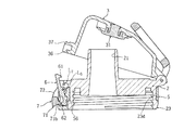
さらに、図4に示すように、第2ロック部材7を起立状姿勢から前下方揺動させると、連結部71の第2係止部71aが第2キャップ係止部37から離脱して、先ず、第2のロックが解除される。そして、第2ロック部材7の連結部71を、さらに、前下方揺動させ、水平状姿勢を介して、垂下状姿勢にまで揺動操作すると、図5に示すように、第2ロック部材7の連結部71の押圧部71bが、第1ロック部材6の被押圧部62を後方へ押圧し、第1ロック部材6の第1係止部61が前方へ揺動して第1キャップ係止部36から離脱して、第1ロックが解除され、キャップ部材3が図示省略の弾発付勢部材の弾発力にて開揺動を開始して、キャップ部材3が後方へ揺動したキャップ開状態(二重ロック解除状態)となる。
Further, as shown in FIG. 4, when the
即ち、使用者は、第2ロック部材7を、起立状姿勢から水平状姿勢を介して垂下状姿勢にする下方への揺動操作にて、第1のロックと第2のロックを解除することが可能である。
つまり、1つの部材を用いて、ワンモーション行うだけで、2つのロックを解除できる。
That is, the user releases the first lock and the second lock by swinging the
That is, two locks can be released only by performing one motion using one member.
また、第2枢着軸心L7を、第1枢着軸心L6よりも上位置に配設することで、被押圧部62を強い力で押圧しないと後方へ揺動しないように(第1のロックが解除されないように)構成している。
Further, by arranging the second pivot center L 7 at a position higher than the first pivot center L 6 , the pressed
例えば、図8に於て実線で示す第2ロック部材7を実施例と呼び、二点鎖線で示す第2ロック部材7´を比較例と呼ぶ。実施例の第2ロック部材7は第2枢着軸心L7で枢着している。比較例の第2ロック部材7´は第1枢着軸心L6で枢着している(第1ロック部材6と同軸心状に設けている)。
実施例の第2ロック部材7の押圧部71bに比べて、比較例の第2ロック部材7´の押圧部71b´は、垂下状姿勢で、下位置に配設されることになる。
つまり、実施例は比較例と比べて、第1ロック部材6の被押圧部62を第1枢着軸心L6に接近させて配設させることができ、被押圧部62を強い力で押圧しないと後方へ揺動しない(第1のロックが解除されない)構成とすることができる。
For example, the
Compared with the
That is, in the embodiment, as compared with the comparative example, the pressed
また、第2枢着軸心L7を、第1枢着軸心L6よりも上位置に配設することで、第2ロック部材7の連結部(揺動操作部)71を、第2ロック部材7を揺動させる際に大きな操作力を付与しやすい配置に構成している。
Further, by disposing the second pivot center L 7 at a position higher than the first pivot center L 6 , the connecting portion (swing operation portion) 71 of the
例えば、図9に於て実線で示す第2ロック部材7を実施例と呼び、二点鎖線で示す第2ロック部材7″を他の比較例と呼ぶ。実施例の第2ロック部材7は第2枢着軸心L7で枢着している。他の比較例の第2ロック部材7″は第1枢着軸心L6で枢着している(第1ロック部材6と同軸心状に設けている)。そして、実施例の押圧部71b及び他の比較例の押圧部71b″は、垂下状姿勢で、第1ロック部材6の被押圧部62を、押圧するように設けている。
For example, the
実施例の第2ロック部材7の連結部71は、他の比較例の第2ロック部材7″の連結部71″に比べて、上位置に配設されることになる。
つまり、実施例の第2ロック部材7の連結部71の先端から自らの枢着点(第2枢着軸心L7)までの実施揺動半径Rと呼び、他の比較例の第2ロック部材7″の連結部71″の先端から自らの枢着点(第1枢着軸心L6)までの距離を比較揺動半径R″と呼ぶと、実施揺動半径Rは、比較揺動半径R″よりも大きくなる。
即ち、実施例は他の比較例に比べて、指等で揺動させやすく、大周りして被押圧部62に接近させることができ、大きな操作力を付与しやすい構成としている。
The connecting
That is, it is called the implementation swing radius R from the tip of the connecting
That is, as compared with other comparative examples, the embodiment is configured to be easily swung with a finger or the like, to be able to make a large turn and approach the pressed
さらに、図1乃至図5に示すように、蓋部材2に、シリコーンゴム等のゴム製の滑り止め用のリング部材5を、外嵌状に取着している。
Further, as shown in FIGS. 1 to 5, a
図6に示すように、蓋部材2は、樹脂製(樹脂成形品)であって、口部21を有する煙突状部が突設された上壁部22と、ボトル本体1の雄ネジ部に螺合する雌ネジ部が内周面に形成された周壁部23と、キャップ部材3が枢着する後方突出状の枢着部24を有している。
さらに、周壁部23は、ラジアル内方へ凹設された外周溝23dを有している。
As shown in FIG. 6, the
Further, the
そして、図7に示すように、滑り止め用のリング部材5は、蓋部材2の外周溝23dに弾性的復元力によって外嵌状に取着する環状部(ゴムバンド部)51と、環状部51の前側の外周面から前方突出状に設けた戻し用弾発付勢部56と、を有している。つまり、リング部材5の一部(前部)をもって戻し用弾発付勢部56を構成している。
Then, as shown in FIG. 7, the
さらに、リング部材5は、図1乃至図5に示すように、組立状態で第1ロック部材6の下部が上方から差込み状に配設され被押圧部62の前面を露出させる前方開口状の窓部52aを前壁部52eに有する上方開口箱形状の保護カバー部52を有している。
Further, as shown in FIGS. 1 to 5, the
第1ロック部材6は、キャップ部材3と係合している起立状姿勢(基準姿勢)において、被押圧部62が保護カバー部52の前壁部52eよりも前方へ突出しないように設けている。
即ち、被押圧部62の上下左右は、保護カバー部52の前壁部52e(の窓枠部)に包囲され、人の指や物等によって押圧されにくい。
The
That is, the upper, lower, left and right sides of the pressed
このように、リング部材5は、環状部51と、戻し用弾発付勢部56と、保護カバー部52と、を一体に有する(設けた)、ゴム製の一体成形品としているので、(別体に設けた場合と比べて)、部品点数の削減や小さな部品の紛失を防止して、組立作業が容易に行えると共に、部品管理を容易にしている。また、リング部材5を取外すことで、第1ロック部材6と蓋部材2の間を容易に洗浄(水洗い)でき衛生的である。
As described above, the
また、第1ロック部材6は、戻し用弾発付勢部56の弾性的復元力(弾発付勢力)を受けて基準位置になると、その基準位置を越えて揺動しないように蓋部材2又はリング部材5に当接して、揺動が阻止される当り部(図示省略)を有している。
言い換えると、蓋部材2又はリング部材5は、第1ロック部材6が戻し用弾発付勢部56からの弾発付勢力を受けて基準位置を越えて揺動しないように阻止するストッパ部(図示省略)を有している。
Further, when the
In other words, the
また、図1乃至図5に示すように、蓋部材2とキャップ部材3との枢着部に、樹脂製の門型形状の持ち手部材4を、水平状軸心L3廻りに揺動自在に枢着している。つまり、蓋部材2の枢着部24には、キャップ部材3と持ち手部材4とが同軸心状に枢着している。
また、蓋部材2とボトル本体1の間をシール(水密)するゴム製の環状シール部材を備えている。
Further, as shown in FIGS. 1 to 5, the pivotally mounted portion of the
Further, a rubber annular seal member for sealing (watertight) between the
なお、本発明の説明を容易にするために、水平状軸心L3とボトル軸心La(図3参照)の両者に直交する方向を前後方向と呼び、キャップ部材3と蓋部材2との枢着部側を後方と呼んでいる。また、水平状軸心L3に沿った方向を左右方向と呼ぶ。したがって、方向を基に、使用状態の姿勢を限定するものではない。水平状軸心L3と第1枢着軸心L6と第2枢着軸心L7は、相互に左右方向に平行状に配設される。
In order to facilitate describing the present invention, referred to a direction perpendicular to both the horizontally axis L 3 and the bottle axis La (see FIG. 3) and the front-rear direction, of the
なお、本発明は、設計変更可能であって、蓋部材2とボトル本体1の取着は、ネジ構造に限らず、係合構造等自由である。リング部材5の環状部51の外周面は、ブランド名やメーカー名や商品面を凹凸成形や塗装等にて表示させる表示部とするも良い。
In the present invention, the design can be changed, and the
以上のように、本発明の携帯用飲料ボトルは、ボトル本体1を施蓋するキャップ部材3を閉状態に保持して第1のロックを行う第1ロック部材6と、上記第1ロック部材6にて閉状態に保持された上記キャップ部材3を起立状姿勢で係止して第2のロックを行う門型の第2ロック部材7と、を備えた携帯用飲料ボトルに於て、上記第2ロック部材7を上記起立状姿勢から下方へ揺動して第2のロックを解除すると共に、下方へ揺動して垂下状姿勢となった上記第2ロック部材7にて上記第1ロック部材6を押圧して第1のロックを解除するように構成したので、第2ロック部材7とキャップ部材3との係合を解除する操作から連続的に(流れるように)、第1ロック部材6とキャップ部材3との係合を解除でき、キャップ部材3を素早く開くことができる。二重ロック構造でありながらも、直観的に、かつ、容易に開操作できて、使い勝手が良い。
As described above, in the portable beverage bottle of the present invention, the
また、有底筒状のボトル本体1と、該ボトル本体1に施蓋状に取着されると共に飲料吐出用の口部21を有する蓋部材2と、上記蓋部材2に揺動自在に枢着されると共に上記口部21を施蓋するためのキャップ部材3と、上記蓋部材2にシーソー状に揺動自在に枢着され上記キャップ部材3を閉状態に保持して第1のロックを行う第1係止部61を上部に有すると共に下部に押圧操作される被押圧部62を有する第1ロック部材6と、上記蓋部材2に起立状姿勢と垂下状姿勢とに揺動切換自在に枢着され上記第1ロック部材6にて閉状態に保持された上記キャップ部材3を起立状姿勢で係止して第2のロックを行う門型の第2ロック部材7と、を備えた携帯用飲料ボトルであって、上記第2ロック部材7は、上記第1ロック部材6の両側に配設される一対の柱部72,72の先端部を連結する連結部71に、上記起立状姿勢で閉状態の上記キャップ部材3に係止する第2係止部71aを有すると共に、上記垂下状姿勢で上記第1ロック部材6の上記被押圧部62を押圧する押圧部71bを有し、上記第2ロック部材7を上記起立状姿勢から下方へ揺動して第2のロックを解除すると共に、下方へ揺動して垂下状姿勢となった上記第2ロック部材7の上記押圧部71bにて上記第1ロック部材6の上記被押圧部62を押圧して第1のロックを解除するように構成したので、第2ロック部材7とキャップ部材3との係合を解除する操作から連続的に(ワンモーションで)、第1ロック部材6とキャップ部材3との係合を解除でき、キャップ部材3を素早く開くことができる。二重ロック構造でありながらも、直観的に、かつ、容易に開操作できて、使い勝手が良い。
Further, the bottomed
また、ゴム製の滑り止め用のリング部材5を上記蓋部材2に外嵌状に取着し、上記第1ロック部材6の下部を前方へ常時弾発付勢するための戻し用弾発付勢部56を、上記リング部材5の一部をもって構成したので、小さなバネ部材を用いる必要がなく、組立や、洗浄時の取外しを容易に行うことができる。部品点数の削減や小さな部品の紛失を防止して、組立作業が容易に行えると共に、部品管理を容易にしている。また、分解洗浄(水洗い)が容易にでき、衛生的である。
Further, a rubber
また、上記第1ロック部材6は、上下中間部が水平状の第1枢着軸心L6廻りに揺動自在に枢着され、上記第2ロック部材7は、水平状の第2枢着軸心L7廻りに揺動自在に枢着され、上記第2枢着軸心L7を、上記第1枢着軸心L6よりも上位置に配設したので、被押圧部62を強い力で押圧しないと後方へ揺動しないように(第1のロックが解除されないように)構成でき、かつ、第2ロック部材7を揺動させる際に大きな操作力を付与しやすい構成とできる。即ち、意図せずに、第2ロック部材7による第2のロックが解除されている状態であっても、第1ロック部材6の被押圧部62に、不意に物や指が触れただけでは、第1のロックは解除されず、安全に持ち運びできる。
Further, the
1 ボトル本体
2 蓋部材
3 キャップ部材
5 リング部材
6 第1ロック部材
7 第2ロック部材
21 口部
56 戻し用弾発付勢部
61 第1係止部
62 被押圧部
71 連結部
71a 第2係止部
71b 押圧部
72 柱部
L6 第1枢着軸心
L7 第2枢着軸心
1
21 mouth
56 Return bullet firing part
61 First locking part
62 Pressed part
71 Connection
71a 2nd locking part
71b Pressing part
72 Pillar part L 6 1st pivot center L 7 2nd pivot center
Claims (4)
上記第2ロック部材(7)を上記起立状姿勢から下方へ揺動して第2のロックを解除すると共に、下方へ揺動して垂下状姿勢となった上記第2ロック部材(7)にて上記第1ロック部材(6)を押圧して第1のロックを解除するように構成したことを特徴とする携帯用飲料ボトル。 The cap member (3) that covers the bottle body (1) is held in the closed state by the first lock member (6) that performs the first lock and the first lock member (6) that holds the bottle body (1) in the closed state. In a portable beverage bottle provided with a gate-shaped second lock member (7) that locks the cap member (3) in an upright position to perform a second lock.
The second lock member (7) is swung downward from the upright posture to release the second lock, and is swung downward to the second lock member (7) in a hanging posture. A portable beverage bottle configured to release the first lock by pressing the first lock member (6).
上記第2ロック部材(7)は、上記第1ロック部材(6)の両側に配設される一対の柱部(72)(72)の先端部を連結する連結部(71)に、上記起立状姿勢で閉状態の上記キャップ部材(3)に係止する第2係止部(71a)を有すると共に、上記垂下状姿勢で上記第1ロック部材(6)の上記被押圧部(62)を押圧する押圧部(71b)を有し、
上記第2ロック部材(7)を上記起立状姿勢から下方へ揺動して第2のロックを解除すると共に、下方へ揺動して垂下状姿勢となった上記第2ロック部材(7)の上記押圧部(71b)にて上記第1ロック部材(6)の上記被押圧部(62)を押圧して第1のロックを解除するように構成したことを特徴とする携帯用飲料ボトル。 A bottomed tubular bottle body (1), a lid member (2) that is attached to the bottle body (1) like a lid and has a mouth portion (21) for discharging a beverage, and the lid member ( The cap member (3) for swingably pivoting to the 2) and covering the mouth portion (21) and the cap member (2) swingably pivotally attached to the lid member (2) in a seesaw shape. A first lock member (6) having a first locking portion (61) for holding the member (3) in the closed state and performing the first locking at the upper portion and a pressed portion (62) to be pressed at the lower portion. ) And the cap member (3), which is pivotally attached to the lid member (2) in an upright position and a hanging position so as to be swingable and held in a closed state by the first lock member (6). A portable beverage bottle provided with a gate-shaped second locking member (7) that locks in an upright position to perform a second locking.
The second lock member (7) stands on a connecting portion (71) connecting the tip portions of a pair of pillar portions (72) (72) arranged on both sides of the first lock member (6). It has a second locking portion (71a) that locks to the cap member (3) in a closed state in a shaped posture, and also has a pressed portion (62) of the first locking member (6) in a hanging posture. It has a pressing part (71b) to press
The second lock member (7) swings downward from the upright posture to release the second lock, and swings downward to take a hanging posture. A portable beverage bottle characterized in that the pressing portion (71b) is configured to press the pressed portion (62) of the first locking member (6) to release the first lock.
上記第1ロック部材(6)の下部を前方へ常時弾発付勢するための戻し用弾発付勢部(56)を、上記リング部材(5)の一部をもって構成した請求項2記載の携帯用飲料ボトル。 A rubber non-slip ring member (5) is attached to the lid member (2) in an outer fit manner.
The second aspect of claim 2, wherein the return elastic urging portion (56) for constantly urging the lower portion of the first lock member (6) forward is formed by a part of the ring member (5). Portable beverage bottle.
上記第2ロック部材(7)は、水平状の第2枢着軸心(L7)廻りに揺動自在に枢着され、
上記第2枢着軸心(L7)を、上記第1枢着軸心(L6)よりも上位置に配設した請求項1,2又は3記載の携帯用飲料ボトル。 The first lock member (6) is swingably pivotally attached around the first pivot center (L 6 ) whose upper and lower intermediate portions are horizontal.
The second lock member (7) is swingably pivotally attached around the horizontal second pivot center (L 7 ).
The portable beverage bottle according to claim 1, 2, or 3, wherein the second pivot center (L 7 ) is arranged above the first pivot center (L 6 ).
Priority Applications (1)
| Application Number | Priority Date | Filing Date | Title |
|---|---|---|---|
| JP2018215558A JP6760665B2 (en) | 2018-11-16 | 2018-11-16 | Portable beverage bottle |
Applications Claiming Priority (1)
| Application Number | Priority Date | Filing Date | Title |
|---|---|---|---|
| JP2018215558A JP6760665B2 (en) | 2018-11-16 | 2018-11-16 | Portable beverage bottle |
Publications (2)
| Publication Number | Publication Date |
|---|---|
| JP2020083331A JP2020083331A (en) | 2020-06-04 |
| JP6760665B2 true JP6760665B2 (en) | 2020-09-23 |
Family
ID=70906070
Family Applications (1)
| Application Number | Title | Priority Date | Filing Date |
|---|---|---|---|
| JP2018215558A Expired - Fee Related JP6760665B2 (en) | 2018-11-16 | 2018-11-16 | Portable beverage bottle |
Country Status (1)
| Country | Link |
|---|---|
| JP (1) | JP6760665B2 (en) |
Cited By (1)
| Publication number | Priority date | Publication date | Assignee | Title |
|---|---|---|---|---|
| EP4529805A1 (en) | 2023-09-27 | 2025-04-02 | Thermos L.L.C. | Cap unit and capped container |
Families Citing this family (4)
| Publication number | Priority date | Publication date | Assignee | Title |
|---|---|---|---|---|
| CN115724069A (en) | 2021-08-25 | 2023-03-03 | 膳魔师(中国)家庭制品有限公司 | Cap unit and beverage container |
| KR20240028937A (en) | 2022-08-25 | 2024-03-05 | 서어모스 케이.케이. | Cap unit and beverage container |
| CN117622696A (en) | 2022-08-25 | 2024-03-01 | 膳魔师(中国)家庭制品有限公司 | Cap unit and beverage container |
| JP2025042092A (en) * | 2023-09-14 | 2025-03-27 | サーモス株式会社 | Cap unit and container with cap |
Family Cites Families (6)
| Publication number | Priority date | Publication date | Assignee | Title |
|---|---|---|---|---|
| JP4798553B2 (en) * | 2008-07-16 | 2011-10-19 | サーモス株式会社 | Beverage container |
| JP3150119U (en) * | 2009-02-13 | 2009-04-30 | 株式会社ドウシシャ | Beverage container stopper and beverage container having the same |
| JP5257503B2 (en) * | 2011-11-21 | 2013-08-07 | サーモス株式会社 | Beverage container closure with lock |
| JP6190676B2 (en) * | 2013-09-18 | 2017-08-30 | レック株式会社 | Infant beverage container |
| JP6228957B2 (en) * | 2015-08-07 | 2017-11-08 | 三菱製鋼株式会社 | Beverage container closure with lock |
| JP6152158B2 (en) * | 2015-11-17 | 2017-06-21 | タケヤ化学工業株式会社 | Portable beverage bottle |
-
2018
- 2018-11-16 JP JP2018215558A patent/JP6760665B2/en not_active Expired - Fee Related
Cited By (2)
| Publication number | Priority date | Publication date | Assignee | Title |
|---|---|---|---|---|
| EP4529805A1 (en) | 2023-09-27 | 2025-04-02 | Thermos L.L.C. | Cap unit and capped container |
| KR20250047149A (en) | 2023-09-27 | 2025-04-03 | 서어모스 케이.케이. | Cap unit and cap-equipped container |
Also Published As
| Publication number | Publication date |
|---|---|
| JP2020083331A (en) | 2020-06-04 |
Similar Documents
| Publication | Publication Date | Title |
|---|---|---|
| JP6760665B2 (en) | Portable beverage bottle | |
| US9038928B2 (en) | Spray gun | |
| KR101472714B1 (en) | Cap of drink container | |
| JP5498613B1 (en) | Beverage container | |
| JP6839748B2 (en) | Cap unit and beverage container | |
| US5084918A (en) | Integral safety helmet | |
| JP2011093544A (en) | Double lock structure for beverage container | |
| JP2015013673A (en) | Beverage container hinge structure | |
| JP3179418U (en) | Portable beverage container | |
| JP3134856U (en) | A pinching mechanism that can quickly pinch spray cans | |
| JP5333812B2 (en) | Container with trigger pump | |
| US20220191670A1 (en) | Transferrable personal electronic assembly | |
| JP6856473B2 (en) | Hinge cap | |
| BR112019016921A2 (en) | vehicle door lock device | |
| JP6830349B2 (en) | Aerosol container | |
| JP6621163B1 (en) | Beverage container locking mechanism | |
| CN209150403U (en) | The mechanical lock buckle structure of charging gun | |
| JP4293355B2 (en) | cap | |
| JP2015066360A (en) | Open / close dual-use wiping body gripping tool and cleaning tool | |
| JP6152158B2 (en) | Portable beverage bottle | |
| CN206651474U (en) | Handles, trolleys and trolley cases | |
| CN218127981U (en) | Cup cover and cup | |
| JP3178720U (en) | Portable beverage container | |
| JP4333874B2 (en) | cap | |
| JP6815190B2 (en) | Aerosol container |
Legal Events
| Date | Code | Title | Description |
|---|---|---|---|
| A621 | Written request for application examination |
Free format text: JAPANESE INTERMEDIATE CODE: A621 Effective date: 20190624 |
|
| TRDD | Decision of grant or rejection written | ||
| A01 | Written decision to grant a patent or to grant a registration (utility model) |
Free format text: JAPANESE INTERMEDIATE CODE: A01 Effective date: 20200817 |
|
| A61 | First payment of annual fees (during grant procedure) |
Free format text: JAPANESE INTERMEDIATE CODE: A61 Effective date: 20200831 |
|
| R150 | Certificate of patent or registration of utility model |
Ref document number: 6760665 Country of ref document: JP Free format text: JAPANESE INTERMEDIATE CODE: R150 |
|
| LAPS | Cancellation because of no payment of annual fees |