具体实施方式Detailed ways
<第一实施方式><First Embodiment>
参照图1~图9对本发明的第一实施方式的盖帽单元3A及具备该盖帽单元3A的饮料用容器1A进行说明。此外,在以下的说明中,存在将盖帽单元3A简称为盖帽、将饮料用容器1A简称为容器的情况。A cap unit 3A according to a first embodiment of the present invention and a drink container 1A including the cap unit 3A will be described with reference to FIGS. 1 to 9 . In addition, in the following description, the cap unit 3A may be simply referred to as a cap, and the beverage container 1A may be simply referred to as a container.
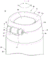
如图1及图2所示,本实施方式的饮料用容器1A具备:盖帽单元3A;和有底筒状的容器主体2A,被安装了盖帽单元3A。盖帽单元3A通过螺合以装卸自如的方式安装于容器主体2A的开口部亦即口颈部2c。As shown in FIGS. 1 and 2 , a beverage container 1A according to the present embodiment includes: a cap unit 3A; and a bottomed cylindrical container body 2A to which the cap unit 3A is attached. The cap unit 3A is detachably attached to the opening of the container body 2A, that is, the mouth and neck portion 2c by screwing.
盖帽单元3A具备:具有顶壁(上壁)的筒状即有顶筒状的盖帽主体9;内栓部10,与盖帽主体9固定;止水密封件14,封闭容器主体2A与盖帽主体9之间;环状的环部件11;以及铰链12,将环部件11相对于盖帽主体9连结为绕铰链中心轴A转动自如。The cap unit 3A has: a cylindrical cap body 9 with a top wall (upper wall), that is, a top cylindrical cap body 9; an inner plug portion 10, fixed with the cap body 9; a water-tight seal 14, which closes the container body 2A and the cap body 9 between them; an annular ring member 11; and a hinge 12 that connects the ring member 11 to the cap main body 9 so as to be rotatable around the hinge central axis A.
盖帽单元3A及容器主体2A以中心轴C为中心相互配置为同轴。The cap unit 3A and the container body 2A are arranged coaxially with each other around the central axis C.
在本实施方式中,将中心轴C延伸的方向称为上下方向。将上下方向中的从容器主体2A的底面部2a朝向盖帽主体9的顶壁部9b的方向称为上侧,将从顶壁部9b朝向底面部2a的方向称为下侧。In this embodiment, the direction in which the central axis C extends is referred to as an up-down direction. Of the up-down directions, the direction from the bottom portion 2a of the container body 2A toward the top wall portion 9b of the cap body 9 is referred to as the upper side, and the direction from the top wall portion 9b toward the bottom portion 2a is referred to as the lower side.
将与中心轴C正交的方向称为径向。将径向中的接近中心轴C的方向称为径向内侧或者简称为内侧、远离中心轴C的方向称为径向外侧或者简称为外侧。The direction perpendicular to the central axis C is called a radial direction. In the radial direction, the direction close to the central axis C is called the radial inner side or simply the inner side, and the direction away from the central axis C is called the radially outer side or simply called the outer side.
另外,将径向中的通过铰链12与中心轴C的方向称为前后方向。将前后方向中的从铰链12朝向中心轴C的方向称为前侧、从中心轴C朝向铰链12的方向称为后侧。In addition, the direction which passes the hinge 12 and the central axis C in a radial direction is called a front-back direction. Of the front-rear directions, the direction from the hinge 12 toward the central axis C is referred to as the front side, and the direction from the central axis C toward the hinge 12 is referred to as the rear side.
另外,将径向中的与前后方向正交的方向称为左右方向。在从前侧观察如图2所示处于盖帽主体9的顶壁部9b朝向铅垂方向的上方的正立姿势的饮料用容器1A时,将左右方向中的朝向左的方向称为左侧、朝向右的方向称为右侧。In addition, the direction orthogonal to the front-back direction in a radial direction is called a left-right direction. When viewing the beverage container 1A in an upright posture in which the top wall portion 9b of the cap main body 9 faces upward in the vertical direction as shown in FIG. The direction to the right is called the right side.
将以中心轴C为中心环绕的方向称为周向。周向相当于盖帽单元3A与容器主体2A螺合的方向(螺合方向)。如图1所示,周向中的一侧T1相当于螺合方向的紧固侧,周向中的另一侧T2相当于螺合方向的松弛侧(螺合解除方向)。因此,在本实施方式中,存在将周向的一侧T1称为周向的紧固侧T1、将周向的另一侧T2称为周向的松弛侧T2的情况。更详细而言,在从上侧观察饮料用容器1A时,周向的一侧(紧固侧)T1为以中心轴C为中心的顺时针方向,周向的另一侧(松弛侧)T2为以中心轴C为中心的逆时针方向。The direction surrounding the central axis C is called a circumferential direction. The circumferential direction corresponds to the direction in which the cap unit 3A is screwed to the container body 2A (screwing direction). As shown in FIG. 1 , one side T1 in the circumferential direction corresponds to the tightening side in the screwing direction, and the other side T2 in the circumferential direction corresponds to the loosening side in the screwing direction (the screwing release direction). Therefore, in this embodiment, one side T1 in the circumferential direction may be referred to as the tightening side T1 in the circumferential direction, and the other side T2 in the circumferential direction may be referred to as the loosening side T2 in the circumferential direction. More specifically, when viewing the beverage container 1A from above, one side in the circumferential direction (tightening side) T1 is clockwise around the central axis C, and the other side in the circumferential direction (loosening side) T2 is It is a counterclockwise direction centered on the central axis C.
此外,对于中心轴C而言,也可以与铰链中心轴A进行区别而改称为盖帽中心轴C或者容器中心轴C。In addition, the central axis C may also be referred to as the cap central axis C or the container central axis C differently from the hinge central axis A.
铰链12的铰链中心轴A配置于比中心轴C靠后侧的位置。中心轴C和铰链中心轴A处于相互扭转的位置。The hinge center axis A of the hinge 12 is arranged on the rear side of the center axis C. As shown in FIG. The central axis C and the hinge central axis A are in mutually twisted positions.
将铰链中心轴A延伸的方向称为铰链轴向。铰链轴向相当于左右方向。铰链轴向中的一侧相当于右侧,另一侧相当于左侧。铰链中心轴A在以中心轴C为中心的未图示的假想圆的切线方向上延伸。因此,铰链轴向的一侧相当于周向的紧固侧T1,铰链轴向的另一侧相当于周向的松弛侧T2(参照图6)。The direction in which the hinge center axis A extends is called the hinge axis. The hinge axis corresponds to the left-right direction. One side in the hinge axis corresponds to the right side, and the other side corresponds to the left side. The hinge central axis A extends in a direction tangential to an unillustrated imaginary circle centered on the central axis C. Therefore, one side in the hinge axial direction corresponds to the tightening side T1 in the circumferential direction, and the other side in the axial direction of the hinge corresponds to the loosening side T2 in the circumferential direction (see FIG. 6 ).
将与铰链中心轴A正交的方向称为铰链径向。将铰链径向中的接近铰链中心轴A的方向称为铰链径向的内侧、远离铰链中心轴A的方向称为铰链径向的外侧。The direction perpendicular to the hinge central axis A is called the hinge radial direction. In the radial direction of the hinge, the direction close to the hinge central axis A is called the inner side of the hinge radial direction, and the direction away from the hinge central axis A is called the outer side of the hinge radial direction.
将以铰链中心轴A为中心环绕的方向称为铰链周向。The direction around the hinge central axis A is referred to as the hinge circumferential direction.
如图2所示,饮料用容器1A能够通过具有真空隔热构造的容器主体2A来对收容于该容器主体2A的饮料(液状的内容物、液体)进行保温或者保冷。容器主体2A为上部开口的有底筒状。此外,在容器主体2A也可以收容除饮料以外的内容物。As shown in FIG. 2 , the beverage container 1A can keep the beverage (liquid content, liquid) contained in the container main body 2A warm or cold by the container main body 2A having a vacuum heat insulation structure. The container main body 2A has a bottomed cylindrical shape with an open top. In addition, contents other than beverages can also be accommodated in the container main body 2A.
具体而言,该容器主体2A具有例如由不锈钢等构成的有底筒状的外容器4及内容器5,由在内容器5收容在外容器4的内侧的状态下将彼此的口边部接合而成的双层构造的容器构成。Specifically, the container main body 2A has a bottomed cylindrical outer container 4 and an inner container 5 made of, for example, stainless steel, and is formed by joining the mouths of each other while the inner container 5 is accommodated inside the outer container 4. It is composed of a double-layer structure container.
另外,在外容器4与内容器5之间设置有真空隔热层6。真空隔热层6例如能够通过在被减压(抽真空)为高真空的腔室内将设置于外容器4的底面中央部的排气孔堵塞来形成。In addition, a vacuum heat insulating layer 6 is provided between the outer container 4 and the inner container 5 . The vacuum heat insulating layer 6 can be formed, for example, by closing an exhaust hole provided in the center of the bottom surface of the outer container 4 in a chamber depressurized (evacuated) to a high vacuum.
容器主体2A具有:大致圆板状的底面部2a;主体部2b,呈大致圆筒状,下端部与底面部2a的外周部连接;以及口颈部2c,配置于主体部2b的上侧,比主体部2b缩径。The container body 2A has: a substantially disc-shaped bottom portion 2a; a substantially cylindrical body portion 2b whose lower end is connected to the outer periphery of the bottom portion 2a; and a neck portion 2c disposed on the upper side of the body portion 2b, The diameter is smaller than that of the main body portion 2b.
口颈部2c的内周部比主体部2b的内周面缩径。口颈部2c的上端部作为容器主体2A的上部开口部2d而开口为圆形状。如图3所示,口颈部2c具有内螺纹部7、凸出部8、肩部2e。The inner peripheral portion of the neck portion 2c is smaller in diameter than the inner peripheral surface of the main body portion 2b. The upper end portion of the neck portion 2c is opened in a circular shape as the upper opening portion 2d of the container main body 2A. As shown in FIG. 3, the neck portion 2c has an internal thread portion 7, a protrusion portion 8, and a shoulder portion 2e.
内螺纹部7配置于口颈部2c的内周部。The female thread portion 7 is disposed on the inner peripheral portion of the neck portion 2c.
凸出部8配置于口颈部2c的内周部,位于比内螺纹部7靠下侧的位置。凸出部8从口颈部2c的内周面向径向内侧突出,遍及周向的整周地延伸。凸出部8为以中心轴C为中心的环状,在口颈部2c中最向内侧突出。The protruding portion 8 is disposed on the inner peripheral portion of the neck portion 2c, and is located below the internal thread portion 7. As shown in FIG. The protruding portion 8 protrudes radially inward from the inner peripheral surface of the mouth and neck portion 2c, and extends over the entire circumference in the circumferential direction. The protruding portion 8 has an annular shape centered on the central axis C, and protrudes most inwardly in the mouth and neck portion 2c.
肩部2e配置于口颈部2c的外周部。肩部2e为随着朝向上侧而缩径的锥状。口颈部2c中的位于比肩部2e靠上侧的位置的部分为在上下方向上延伸的大致圆筒状。The shoulder portion 2e is disposed on the outer peripheral portion of the mouth and neck portion 2c. The shoulder portion 2e has a tapered shape that decreases in diameter toward the upper side. A portion located above the shoulder portion 2e in the mouth and neck portion 2c has a substantially cylindrical shape extending in the vertical direction.
此外,本实施方式的饮料用容器1A如图1所示整体上具有大致圆筒状的外观形状,但关于饮料用容器1A的外观形状,并不特别限定,能够结合尺寸、设计等来适当地加以变更。另外,也可以在容器主体2A、盖帽主体9以及环部件11的各外表面(表面)实施涂装、印刷等。In addition, the beverage container 1A of the present embodiment has a substantially cylindrical appearance as a whole as shown in FIG. be changed. In addition, painting, printing, etc. may be performed on the respective outer surfaces (surfaces) of the container main body 2A, the cap main body 9, and the ring member 11 .
如图3及图4所示,盖帽单元3A安装于容器主体2A的口颈部2c,构成将容器主体2A的上部开口部2d封堵的栓体。此外,图3是表示盖帽单元3A的环部件11的收纳状态的剖视图,图4是表示盖帽单元3A的环部件11的敞开状态的剖视图。图3及图4均表示与中心轴C平行的(包含中心轴C的)纵剖视图。As shown in FIGS. 3 and 4 , the cap unit 3A is attached to the neck portion 2c of the container body 2A, and constitutes a plug that closes the upper opening portion 2d of the container body 2A. In addition, FIG. 3 is a cross-sectional view showing a housed state of the ring member 11 of the cap unit 3A, and FIG. 4 is a cross-sectional view showing an opened state of the ring member 11 of the cap unit 3A. Both FIGS. 3 and 4 are longitudinal cross-sectional views parallel to the central axis C (including the central axis C).
盖帽主体9是封堵容器主体2A的上部开口部2d的部件,例如由聚丙烯(PP)等耐热性树脂构成。盖帽主体9具有周壁部9a和顶壁部9b。The cap main body 9 is a member that closes the upper opening 2d of the container main body 2A, and is made of heat-resistant resin such as polypropylene (PP), for example. The cap main body 9 has a peripheral wall portion 9a and a top wall portion 9b.
周壁部9a为以与容器主体2A的主体部2b连续的方式在上下方向上延伸的筒状。具体而言,在本实施方式中,周壁部9a为随着朝向上侧而缩径的锥筒状。周壁部9a从径向外侧遍及周向整周地包围口颈部2c的外周部。周壁部9a的下端从上侧覆盖肩部2e。The peripheral wall portion 9a has a cylindrical shape extending in the vertical direction so as to be continuous with the main body portion 2b of the container main body 2A. Specifically, in the present embodiment, the peripheral wall portion 9 a has a tapered cylindrical shape whose diameter decreases toward the upper side. The peripheral wall portion 9a surrounds the outer peripheral portion of the mouth and neck portion 2c over the entire circumference in the circumferential direction from the radially outer side. The lower end of the peripheral wall portion 9a covers the shoulder portion 2e from the upper side.
顶壁部9b与周壁部9a的上端部连接,从上侧覆盖容器主体2A的上部开口部2d。顶壁部9b为在与中心轴C垂直的方向上扩展的大致板状。在顶壁部9b与上部开口部2d之间,在上下方向上设置有间隙。The top wall portion 9b is connected to the upper end portion of the peripheral wall portion 9a, and covers the upper opening portion 2d of the container main body 2A from above. The top wall portion 9b has a substantially plate shape extending in a direction perpendicular to the central axis C. As shown in FIG. Between the ceiling wall part 9b and the upper opening part 2d, the clearance gap is provided in the up-down direction.
顶壁部9b具有外周槽9c。外周槽9c配置于顶壁部9b的外周部。外周槽9c比顶壁部9b中的除外周槽9c以外的部分向下侧凹陷,并在周向上延伸。外周槽9c为以中心轴C为中心的环状。外周槽9c在俯视观察时呈大致多边形状,在本实施方式中呈大致四边形状。外周槽9c位于盖帽主体9的上端外周部,并向上侧及径向外侧开口。The top wall portion 9b has an outer peripheral groove 9c. The outer peripheral groove 9c is arranged on the outer peripheral portion of the top wall portion 9b. The outer peripheral groove 9c is recessed below the portion of the top wall portion 9b other than the outer peripheral groove 9c, and extends in the circumferential direction. The outer peripheral groove 9c is annular with the center axis C as the center. The outer peripheral groove 9c has a substantially polygonal shape in plan view, and has a substantially quadrangular shape in this embodiment. The outer peripheral groove 9c is located on the upper end outer peripheral portion of the cap main body 9, and opens upward and radially outward.
如图3及图4所示,在与中心轴C平行的纵剖面观察中,外周槽9c的壁面(槽的内壁)随着朝向径向外侧而朝向下侧延伸。具体而言,在本实施方式中,外周槽9c在该纵剖面观察中呈凹曲线状。即,外周槽9c的壁面为凹曲面状。As shown in FIGS. 3 and 4 , when viewed in a longitudinal section parallel to the central axis C, the wall surface (inner wall of the groove) of the outer peripheral groove 9 c extends downward as it goes radially outward. Specifically, in the present embodiment, the outer peripheral groove 9c has a concave curve shape when viewed in the longitudinal section. That is, the wall surface of the outer peripheral groove 9c is concavely curved.
内栓部10例如由聚丙烯(PP)等耐热性树脂构成。内栓部10与盖帽主体9一体化来封堵上部开口部2d。如图3所示,内栓部10为有底圆筒状,通过熔接等一体地安装于盖帽主体9的顶壁部9b的下表面。内栓部10配置在容器主体2A的口颈部2c内。在内栓部10的内部配置有隔热材料S。此外,也能够替代隔热材料S而使内栓部10的内部为空气层。The inner plug part 10 is made of heat-resistant resin such as polypropylene (PP), for example. The inner plug portion 10 is integrated with the cap body 9 to close the upper opening 2d. As shown in FIG. 3 , the inner plug portion 10 has a bottomed cylindrical shape, and is integrally attached to the lower surface of the top wall portion 9 b of the cap main body 9 by welding or the like. The inner plug portion 10 is disposed in the mouth and neck portion 2c of the container body 2A. A heat insulating material S is disposed inside the inner plug portion 10 . In addition, instead of the heat insulating material S, it is also possible to make the inside of the inner plug part 10 an air layer.
内栓部10具有外螺纹部13和凸缘部10a。The inner plug portion 10 has an external thread portion 13 and a flange portion 10a.
外螺纹部13设置于内栓部10的外周面。在本实施方式的饮料用容器1A中,内栓部10(盖帽单元3A)通过外螺纹部13与内螺纹部7的螺合以装卸自如的方式安装于容器主体2A。The external thread portion 13 is provided on the outer peripheral surface of the internal plug portion 10 . In the beverage container 1A of the present embodiment, the inner plug portion 10 (cap unit 3A) is detachably attached to the container body 2A by screwing the male thread portion 13 and the female thread portion 7 .
凸缘部10a从内栓部10的下端部向径向外侧突出,遍及周向的整周地延伸。凸缘部10a配置于凸出部8的内侧,在径向上与凸出部8对置。The flange portion 10a protrudes radially outward from the lower end portion of the inner plug portion 10, and extends over the entire circumference in the circumferential direction. The flange portion 10a is arranged inside the protrusion portion 8 and faces the protrusion portion 8 in the radial direction.
止水密封件14安装于内栓部10的外周部。止水密封件14是将容器主体2A与内栓部10之间封闭的环状的密封部件,例如由硅橡胶等具有耐热性的橡胶、弹性体等弹性部件构成。在止水密封件14的内周部,遍及周向的整周地设置有朝向径向外侧凹陷的内周凹部14a。止水密封件14通过内周凹部14a嵌装于凸缘部10a来安装于内栓部10。The water-tight seal 14 is attached to the outer peripheral portion of the inner plug portion 10 . The water-tight seal 14 is an annular sealing member that seals between the container main body 2A and the inner plug portion 10 , and is made of, for example, heat-resistant rubber such as silicon rubber, or an elastic member such as an elastomer. On the inner peripheral portion of the water-tight packing 14 , an inner peripheral recessed portion 14 a recessed radially outward is provided over the entire circumference in the circumferential direction. The water stop packing 14 is attached to the inner plug part 10 by fitting the inner peripheral recessed part 14a into the flange part 10a.
在止水密封件14的外周面,向径向外侧突出地设置有弹性凸缘部14b。弹性凸缘部14b配置于止水密封件14的外周部,遍及周向的整周地延伸。弹性凸缘部14b在上下方向上排列设置有2个。当在容器主体2A安装了盖帽单元3A时,弹性凸缘部14b发生弹性变形来成为遍及整周地紧贴于容器主体2A的凸出部8的状态。由此,止水密封件14能够将凸出部8(容器主体2A)与内栓部10(盖帽单元3A)之间封闭为液密。On the outer peripheral surface of the water-tight packing 14, an elastic flange portion 14b is provided so as to protrude radially outward. The elastic flange part 14b is arrange|positioned at the outer peripheral part of the watertight packing 14, and extends over the whole circumference of a circumferential direction. Two elastic flange parts 14b are arranged in a row in the up-down direction. When the cap unit 3A is attached to the container main body 2A, the elastic flange portion 14b is elastically deformed to be in close contact with the protrusion 8 of the container main body 2A over the entire circumference. Thereby, the water-tight seal 14 can seal liquid-tightly between the protrusion part 8 (container main body 2A) and the inner plug part 10 (cap unit 3A).
止水密封件14能够通过拉伸伸长其自身来弹性变形,从凸缘部10a拆下。由此,能够分别清洗盖帽单元3A和止水密封件14,能够卫生地保持止水密封件14与内栓部10之间。The water stop packing 14 can be elastically deformed by stretching itself, and can be detached from the flange portion 10a. Thereby, the cap unit 3A and the water-tight packing 14 can be cleaned separately, and the space between the water-tight packing 14 and the inner plug portion 10 can be maintained hygienically.
此外,关于止水密封件14,并不局限于上述的形状,例如,关于弹性凸缘部14b的数量,并不局限于上述的2个,也能够为1个或者3个以上的多个。另外,止水密封件14并不限定于设置了上述的弹性凸缘部14b的结构,能够对其形状等适当地加以变更。In addition, the waterproof seal 14 is not limited to the above-mentioned shape, for example, the number of the elastic flange parts 14b is not limited to the above-mentioned two, and may be one or three or more. In addition, the waterproof packing 14 is not limited to the structure provided with the above-mentioned elastic flange part 14b, The shape etc. can be changed suitably.
在本实施方式的饮料用容器1A中,能够通过从内栓部10从上部开口部2d嵌入至容器主体2A的内侧的状态如图1及图5所示地使盖帽主体9(盖帽单元3A)相对于容器主体2A向周向的一侧(紧固侧)T1旋转来通过内螺纹部7与外螺纹部13的螺合将盖帽单元3A安装于容器主体2A。In the beverage container 1A of the present embodiment, the cap main body 9 (cap unit 3A) can be moved as shown in FIG. 1 and FIG. The cap unit 3A is attached to the container body 2A by screwing the internal thread portion 7 and the external thread portion 13 by rotating one side (tightening side) T1 in the circumferential direction with respect to the container body 2A.
另外,能够通过从盖帽单元3A安装于容器主体2A的状态使盖帽主体9(盖帽单元3A)相对于容器主体2A向周向的另一侧(松弛侧)T2旋转来解除内螺纹部7与外螺纹部13的螺合,从容器主体2A拆下盖帽单元3A。In addition, by rotating the cap main body 9 (cap unit 3A) to the other side (relaxed side) T2 in the circumferential direction relative to the container main body 2A from the state where the cap unit 3A is attached to the container main body 2A, the connection between the internal thread portion 7 and the external thread can be released. The screwing of the threaded portion 13 detaches the cap unit 3A from the container body 2A.
环部件11例如由聚丙烯(PP)等耐热性树脂构成。环部件11为以中心轴C为中心的环状。环部件11呈大致多边形状,在本实施方式中呈大致四边形状。The ring member 11 is made of heat-resistant resin such as polypropylene (PP), for example. The ring member 11 has a ring shape centered on the central axis C. As shown in FIG. The ring member 11 has a substantially polygonal shape, and in this embodiment has a substantially quadrangular shape.
如图3所示,环部件11配置于盖帽主体9的上侧。具体而言,在图3所示的环部件11的收纳状态下,环部件11配置于顶壁部9b上,更详细而言,配置于顶壁部9b的外周部上即外周槽9c上。环部件11中的至少下侧部分收容在外周槽9c内。As shown in FIG. 3 , the ring member 11 is disposed on the upper side of the cap main body 9 . Specifically, in the accommodated state of the ring member 11 shown in FIG. 3 , the ring member 11 is arranged on the top wall portion 9b, more specifically, on the outer peripheral portion of the top wall portion 9b, that is, on the outer peripheral groove 9c. At least the lower portion of the ring member 11 is accommodated in the outer peripheral groove 9c.
环部件11的下表面11a为以中心轴C为中心的环状。环部件11的下表面11a形成为仿照该下表面11a所对置的盖帽主体9的顶壁部9b的形状的形状。即,环部件11的下表面11a为仿照了外周槽9c的槽形状的形状。具体而言,在图3所示的纵剖面观察中,环部件11的下表面11a随着朝向径向内侧而朝向上侧延伸。在本实施方式中,环部件11的下表面11a在该纵剖面观察中呈凸曲线状。即,环部件11的下表面11a为凸曲面状。The lower surface 11 a of the ring member 11 has a ring shape centered on the central axis C. As shown in FIG. The lower surface 11a of the ring member 11 is formed in a shape following the shape of the top wall portion 9b of the cap main body 9 that the lower surface 11a faces. That is, the lower surface 11a of the ring member 11 has a shape following the groove shape of the outer peripheral groove 9c. Specifically, in a longitudinal cross-sectional view shown in FIG. 3 , the lower surface 11 a of the ring member 11 extends upward as it goes radially inward. In this embodiment, the lower surface 11a of the ring member 11 has a convex curve shape when viewed in this longitudinal section. That is, the lower surface 11a of the ring member 11 is convexly curved.
环部件11的下表面11a的内周部与外周槽9c的朝向径向外侧的壁面对置。环部件11的内周部与外周槽9c的上述壁面相互嵌合。环部件11及外周槽9c分别为多边形状,因而通过他们的嵌合可使环部件11与外周槽9c在周向上无法相对转动。The inner peripheral portion of the lower surface 11a of the ring member 11 faces the radially outer wall surface of the outer peripheral groove 9c. The inner peripheral portion of the ring member 11 and the above-mentioned wall surface of the outer peripheral groove 9c are fitted into each other. Since the ring member 11 and the outer peripheral groove 9c each have a polygonal shape, the ring member 11 and the outer peripheral groove 9c cannot rotate relative to each other in the circumferential direction by fitting them together.
环部件11的外周面11b随着朝向上侧而朝向径向内侧延伸。即,环部件11的外周面11b为随着朝向上侧而缩径的锥面状。在本实施方式中,环部件11的外周面11b以与盖帽主体9的周壁部9a的外周面连续的方式配置为与周壁部9a大致平齐。The outer peripheral surface 11b of the ring member 11 extends radially inward as it goes upward. That is, the outer peripheral surface 11b of the ring member 11 has a tapered surface shape whose diameter decreases toward the upper side. In the present embodiment, the outer peripheral surface 11 b of the ring member 11 is disposed substantially flush with the peripheral wall portion 9 a so as to be continuous with the outer peripheral surface of the peripheral wall portion 9 a of the cap main body 9 .
环部件11在其上表面具有平面部11c和凹面部11d。The ring member 11 has a planar portion 11c and a concave portion 11d on its upper surface.
平面部11c配置于环部件11的上表面中的外周部。平面部11c为以中心轴C为中心的环状。平面部11c为在与中心轴C垂直的方向上扩展的大致平面状。The flat portion 11c is arranged on the outer peripheral portion of the upper surface of the ring member 11 . The planar portion 11c is annular with the center axis C as the center. The planar portion 11c has a substantially planar shape extending in a direction perpendicular to the central axis C. As shown in FIG.
凹面部11d配置于环部件11的上表面中的除外周部以外的部分即位于比平面部11c靠内侧的部分。凹面部11d比平面部11c更向下侧凹陷。凹面部11d为以中心轴C为中心的环状。在图3所示的纵剖面观察中,凹面部11d随着朝向径向外侧而朝向上侧延伸。具体而言,凹面部11d在该纵剖面观察中呈凹曲线状。即,凹面部11d为凹曲面状。凹面部11d的内周部形成为与顶壁部9b中的位于外周槽9c的内侧的部分平滑地相连。The concave portion 11d is disposed on a portion of the upper surface of the ring member 11 other than the outer peripheral portion, that is, a portion located inside the flat portion 11c. The concave portion 11d is recessed further downward than the flat portion 11c. 11 d of concave parts are ring-shaped centering on the central axis C. As shown in FIG. The concave portion 11 d extends upward as it goes radially outward in a longitudinal cross-sectional view shown in FIG. 3 . Specifically, the concave portion 11d has a concave curved shape when viewed in the longitudinal section. That is, the concave portion 11d has a concave curved shape. The inner peripheral portion of the concave portion 11d is formed to be smoothly connected to a portion of the top wall portion 9b located inside the outer peripheral groove 9c.
在本实施方式中,环部件11中的下侧部分配置在外周槽9c内,外周面11b形成为与周壁部9a连续,凹面部11d形成为与顶壁部9b的内侧部分连续,因此虽然设置环部件11,但提高了外观上的美观。In the present embodiment, the lower portion of the ring member 11 is disposed in the outer peripheral groove 9c, the outer peripheral surface 11b is formed continuously with the peripheral wall portion 9a, and the concave portion 11d is formed continuously with the inner portion of the top wall portion 9b. The ring member 11 has improved appearance.
另外,在环部件11的外表面(表面)设置凹凸,因而在如图4所示使环部件11成为敞开状态、使用者使手指穿过环部件11来把持时,不易打滑,容易稳定地把持。In addition, since the outer surface (surface) of the ring member 11 is provided with irregularities, when the ring member 11 is opened as shown in FIG. .
铰链12将盖帽主体9的后部与环部件11的后部连结为在铰链周向上相对转动自如。铰链12具备包括后述的施力部19及封入部20的弹力机构。铰链12构成为以铰链中心轴A为中心,并在铰链轴向上延伸。The hinge 12 connects the rear portion of the cap main body 9 and the rear portion of the ring member 11 so as to be relatively rotatable in the hinge circumferential direction. The hinge 12 includes an elastic mechanism including a biasing portion 19 and an enclosing portion 20 which will be described later. The hinge 12 is formed centering on the hinge central axis A and extending in the hinge axial direction.
如图5~图9所示,铰链12具有盖帽轴承部15、环轴承部16、17、施力部19、封入部20、铰链轴18。此外,图6示出铰链12的与盖帽单元3A的中心轴C平行的剖面(纵剖面)。另外,对于图7及图8所示的盖帽单元3A的分解立体图而言,构成部件的排列顺序和组装后(组装了的状态)的构成部件的配置关系局部不同。As shown in FIGS. 5 to 9 , the hinge 12 has a cap bearing portion 15 , ring bearing portions 16 , 17 , a biasing portion 19 , a sealing portion 20 , and a hinge shaft 18 . In addition, FIG. 6 shows a cross section (longitudinal cross section) of the hinge 12 parallel to the central axis C of the cap unit 3A. In the exploded perspective views of the cap unit 3A shown in FIGS. 7 and 8 , the arrangement order of the components and the arrangement relationship of the components after assembly (assembled state) are partially different.
盖帽轴承部15与环轴承部16、17中的一方在铰链轴向上相互空开间隔地设置有2个,盖帽轴承部15与环轴承部16、17中的另一方在2个上述一方间配置有1个。在本实施方式中,盖帽轴承部15与环轴承部16、17中的环轴承部16、17在铰链轴向上相互空开间隔地设置有2个,盖帽轴承部15在2个环轴承部16、17间配置有1个。One of the cap bearing part 15 and the ring bearing part 16, 17 is provided with two spaced apart from each other in the hinge axial direction, and the other of the cap bearing part 15 and the ring bearing part 16, 17 is between the two above-mentioned ones. There is 1 configuration. In this embodiment, two of the ring bearings 16, 17 of the block bearing portion 15 and the ring bearing portions 16, 17 are arranged at a distance from each other in the hinge axial direction, and the block bearing portion 15 is located between the two ring bearing portions. Room 16 and Room 17 are equipped with one.
盖帽轴承部15从盖帽主体9的周壁部9a的上端部朝向后侧上方突出设置。即,盖帽轴承部15设置于盖帽主体9。盖帽轴承部15和盖帽主体9通过单个部件形成为一体。盖帽轴承部15为在铰链轴向上延伸的大致圆筒状。盖帽轴承部15位于盖帽主体9的后部中的左右方向的中央部。盖帽轴承部15位于铰链12中的铰链轴向的中央部。The cap bearing portion 15 protrudes upward from the upper end portion of the peripheral wall portion 9 a of the cap main body 9 toward the rear side. That is, the cap bearing portion 15 is provided on the cap main body 9 . The cap bearing portion 15 and the cap main body 9 are integrally formed by a single component. The cap bearing portion 15 has a substantially cylindrical shape extending in the hinge axial direction. The cap bearing portion 15 is located at the central portion in the left-right direction in the rear portion of the cap main body 9 . The cap bearing portion 15 is located in the hinge axial center portion of the hinge 12 .
如图6及图9所示,盖帽轴承部15具有收容凹部15b、臂承受部15c、滑动接触面15d、轴孔15a。即,铰链12具有收容凹部15b。As shown in FIGS. 6 and 9 , the cap bearing portion 15 has a housing recess 15b, an arm receiving portion 15c, a sliding contact surface 15d, and a shaft hole 15a. That is, the hinge 12 has the accommodation recessed part 15b.
在本实施方式中,收容凹部15b凹设于盖帽轴承部15并在铰链轴向上延伸。具体而言,收容凹部15b为以铰链中心轴A为中心的多级圆孔状,在盖帽轴承部15的朝向铰链轴向的一侧的端面开口,从该端面朝向铰链轴向的另一侧延伸。In this embodiment, the receiving recessed portion 15b is recessed in the cap bearing portion 15 and extends in the axial direction of the hinge. Specifically, the accommodating recessed portion 15b is a multi-stage circular hole centered on the hinge central axis A, and is opened on the end face of the cap bearing portion 15 facing one side of the hinge axial direction, and is opened from the end face toward the other side of the hinge axial direction. extend.
收容凹部15b具有大径孔部15f和小径孔部15e。The housing recess 15b has a large-diameter hole 15f and a small-diameter hole 15e.
大径孔部15f为圆孔状,在盖帽轴承部15的朝向铰链轴向的一侧的端面开口。大径孔部15f配置于收容凹部15b中的铰链轴向的一侧的部分。The large-diameter hole portion 15f has a circular hole shape and is opened on the end surface of the cap bearing portion 15 facing the hinge axial direction. The large-diameter hole portion 15f is arranged at one side of the hinge axial direction in the accommodation recessed portion 15b.
小径孔部15e配置于收容凹部15b中的铰链轴向的另一侧的部分。小径孔部15e为内径尺寸小于大径孔部15f的圆孔状,在大径孔部15f的底面开口。The small-diameter hole portion 15e is arranged at the other side of the hinge axial direction in the accommodation recessed portion 15b. The small-diameter hole portion 15e has a circular hole shape with an inner diameter smaller than that of the large-diameter hole portion 15f, and opens on the bottom surface of the large-diameter hole portion 15f.
臂承受部15c配置在收容凹部15b内,为在铰链轴向上延伸的槽状。具体而言,臂承受部15c从大径孔部15f的内周面向铰链径向的外侧凹陷,在铰链轴向上延伸。The arm receiving part 15c is arranged in the receiving recessed part 15b, and is in the shape of a groove extending in the hinge axial direction. Specifically, the arm receiving portion 15c is recessed outward in the hinge radial direction from the inner peripheral surface of the large-diameter hole portion 15f, and extends in the hinge axial direction.
滑动接触面15d配置于盖帽轴承部15的朝向铰链轴向的另一侧的端面。滑动接触面15d为在与铰链中心轴A垂直的方向上扩展的平面状。The sliding contact surface 15 d is disposed on the end surface of the cap bearing portion 15 facing the other side in the hinge axial direction. The sliding contact surface 15d has a planar shape extending in a direction perpendicular to the hinge central axis A. As shown in FIG.
轴孔15a为在铰链轴向上延伸的圆孔状。轴孔15a的内径尺寸小于收容凹部15b,具体而言,内径尺寸小于小径孔部15e。轴孔15a的铰链轴向的一侧的端部在小径孔部15e的底面开口。轴孔15a的铰链轴向的另一侧的端部在滑动接触面15d开口。The shaft hole 15a is in the shape of a circular hole extending in the axial direction of the hinge. The inner diameter of the shaft hole 15a is smaller than that of the housing recess 15b, specifically, the inner diameter is smaller than that of the small-diameter hole 15e. An end portion on one side in the hinge axial direction of the shaft hole 15a is opened to the bottom surface of the small-diameter hole portion 15e. The other end portion of the shaft hole 15a in the hinge axial direction opens to the sliding contact surface 15d.
如图6~图8所示,环轴承部16、17设置于环部件11,配置为与盖帽轴承部15在铰链轴向上相邻。环轴承部16、17和环部件11通过单个部件形成为一体。在本实施方式中,环轴承部16、17设置有2个。As shown in FIGS. 6 to 8 , the ring bearings 16 and 17 are provided on the ring member 11 and arranged adjacent to the cap bearing 15 in the hinge axial direction. The ring bearing portions 16, 17 and the ring member 11 are integrally formed by a single member. In this embodiment, two ring bearing portions 16 and 17 are provided.
2个环轴承部16、17包括第一环轴承部16和第二环轴承部17。第一环轴承部16配置于2个环轴承部16、17中的铰链轴向的一侧。第二环轴承部17配置于2个环轴承部16、17中的铰链轴向的另一侧。The two ring bearings 16 and 17 include a first ring bearing 16 and a second ring bearing 17 . The first ring bearing portion 16 is arranged on one side of the hinge axial direction among the two ring bearing portions 16 and 17 . The second ring bearing portion 17 is disposed on the other side of the two ring bearing portions 16 , 17 in the hinge axial direction.
第一环轴承部16从环部件11的外周面11b的后方下端部朝向后侧突出设置。第一环轴承部16配置为与盖帽轴承部15的铰链轴向的一侧相邻。第一环轴承部16为在铰链轴向上延伸的大致圆筒状。The first ring bearing portion 16 protrudes toward the rear side from the rear lower end portion of the outer peripheral surface 11 b of the ring member 11 . The first ring bearing portion 16 is disposed adjacent to one side of the cap bearing portion 15 in the hinge axial direction. The first ring bearing portion 16 has a substantially cylindrical shape extending in the hinge axial direction.
第一环轴承部16具有轴承滑动面16b和轴孔16a。即,铰链12具有轴承滑动面16b,在本实施方式中,轴承滑动面16b配置于第一环轴承部(环轴承部)16。The first ring bearing portion 16 has a bearing sliding surface 16b and a shaft hole 16a. That is, the hinge 12 has the bearing sliding surface 16b, and in this embodiment, the bearing sliding surface 16b is arrange|positioned at the 1st ring bearing part (ring bearing part) 16. As shown in FIG.
轴承滑动面16b配置于第一环轴承部16的朝向铰链轴向的另一侧的端面。轴承滑动面16b为在与铰链中心轴A垂直的方向上扩展的平面状。The bearing sliding surface 16 b is disposed on the other end surface of the first ring bearing portion 16 facing the hinge axial direction. The bearing sliding surface 16b has a planar shape extending in a direction perpendicular to the hinge central axis A. As shown in FIG.
在本实施方式中,轴承滑动面16b具有台阶部16c。台阶部16c为从轴承滑动面16b向铰链轴向的一侧凹陷的凹状。台阶部16c配置于轴承滑动面16b中的铰链周向的一部分。具体而言,在本实施方式中,在环部件11处于收纳状态时,台阶部16c配置于轴承滑动面16b的下端部。In this embodiment, the bearing sliding surface 16b has a stepped portion 16c. The stepped portion 16c is concave from the bearing sliding surface 16b to one side in the hinge axial direction. The stepped portion 16c is disposed on a part of the bearing sliding surface 16b in the hinge circumferential direction. Specifically, in the present embodiment, when the ring member 11 is in the accommodated state, the stepped portion 16c is arranged at the lower end portion of the bearing sliding surface 16b.
轴孔16a在铰链轴向上贯通第一环轴承部16。轴孔16a的铰链轴向的另一侧的端部在轴承滑动面16b开口。轴孔16a为在铰链轴向上延伸的多级圆孔状。对于轴孔16a中的除铰链轴向的一侧的端部以外的部分而言,内径尺寸小于铰链轴向的一侧的端部。The shaft hole 16a penetrates through the first ring bearing portion 16 in the hinge axial direction. The other end portion of the shaft hole 16a in the hinge axial direction opens to the bearing sliding surface 16b. The shaft hole 16a is in the shape of a multistage circular hole extending in the axial direction of the hinge. The inner diameter dimension of the shaft hole 16a other than the end portion on one side in the hinge axial direction is smaller than the end portion on the one side in the hinge axial direction.
第二环轴承部17从环部件11的外周面11b的后方下端部朝向后侧突出设置。第二环轴承部17配置为与盖帽轴承部15的铰链轴向的另一侧相邻。第二环轴承部17为在铰链轴向上延伸的大致圆筒状。The second ring bearing portion 17 protrudes toward the rear side from the rear lower end portion of the outer peripheral surface 11 b of the ring member 11 . The second ring bearing portion 17 is disposed adjacent to the other side of the cap bearing portion 15 in the hinge axial direction. The second ring bearing portion 17 has a substantially cylindrical shape extending in the hinge axial direction.
第二环轴承部17具有滑动接触凸部17b、抵接面17c、轴孔17a。The second ring bearing portion 17 has a sliding contact convex portion 17b, a contact surface 17c, and a shaft hole 17a.
滑动接触凸部17b位于第二环轴承部17中的铰链轴向的一侧的端部。滑动接触凸部17b从第二环轴承部17中的除铰链轴向的一侧的端部以外的部分、即除滑动接触凸部17b以外的部分向铰链轴向的一侧突出设置。滑动接触凸部17b为在铰链轴向上延伸的圆筒状。滑动接触凸部17b的外径尺寸小于第二环轴承部17中的除滑动接触凸部17b以外的部分。The sliding contact convex portion 17 b is located at the end portion of the second ring bearing portion 17 on one side in the hinge axial direction. The sliding contact protrusion 17b protrudes from the second ring bearing portion 17 except for the hinge axial end, that is, the portion other than the sliding contact protrusion 17b to the hinge axial side. The sliding contact protrusion 17b has a cylindrical shape extending in the hinge axial direction. The outer diameter dimension of the sliding contact convex portion 17 b is smaller than that of the portion other than the sliding contact convex portion 17 b in the second ring bearing portion 17 .
抵接面17c配置于第二环轴承部17的朝向铰链轴向的一侧的端面。在本实施方式中,抵接面17c配置于滑动接触凸部17b的朝向铰链轴向的一侧的端面。抵接面17c为在与铰链中心轴A垂直的方向上扩展的平面状。抵接面17c与盖帽轴承部15的滑动接触面15d以滑动自如的方式接触。The contact surface 17c is arranged on the end surface of the second ring bearing portion 17 facing the hinge axial direction. In this embodiment, the contact surface 17c is arranged on the end surface of the sliding contact convex portion 17b facing the hinge axial side. The contact surface 17c has a planar shape extending in a direction perpendicular to the hinge center axis A. As shown in FIG. The contact surface 17c is in slidable contact with the sliding contact surface 15d of the cap bearing portion 15 .
轴孔17a在铰链轴向上贯通第二环轴承部17。轴孔17a的铰链轴向的一侧的端部在抵接面17c开口。轴孔17a为在铰链轴向上延伸的多级圆孔状。对于轴孔17a中的除铰链轴向的另一侧的端部以外的部分而言,内径尺寸小于铰链轴向的另一侧的端部。The shaft hole 17a penetrates through the second ring bearing portion 17 in the hinge axial direction. One end portion of the shaft hole 17a in the hinge axial direction opens to the contact surface 17c. The shaft hole 17a is in the shape of a multistage circular hole extending in the axial direction of the hinge. In the shaft hole 17a except for the end portion on the other side in the hinge axial direction, the inner diameter dimension is smaller than the end portion on the other side in the hinge axial direction.
施力部19可弹性变形。具体而言,在本实施方式中,施力部19呈以铰链中心轴A为中心的螺旋状,是在铰链轴向上可弹性变形的金属制的压缩螺旋弹簧。施力部19收容于收容凹部15b。施力部19配置为遍及收容凹部15b的小径孔部15e及大径孔部15f。施力部19的铰链轴向的另一侧的端部与小径孔部15e的底面接触。施力部19的铰链轴向的一侧的端部与封入部20的朝向铰链轴向的另一侧的端面(后述的施力部抵接面20d)接触。The biasing portion 19 is elastically deformable. Specifically, in the present embodiment, the urging portion 19 has a helical shape centered on the hinge center axis A, and is a metal compression coil spring elastically deformable in the hinge axis direction. The urging part 19 is accommodated in the accommodation recessed part 15b. The urging part 19 is arrange|positioned over the small-diameter hole part 15e and the large-diameter hole part 15f of the accommodation recessed part 15b. The other end portion in the hinge axial direction of the urging portion 19 is in contact with the bottom surface of the small-diameter hole portion 15e. One end in the hinge axial direction of the urging portion 19 is in contact with an end surface (an urging portion abutting surface 20 d described later) facing the other side in the hinge axial direction of the enclosing portion 20 .
施力部19相对于盖帽轴承部15经由封入部20朝向铰链轴向的一侧对第一环轴承部16施力。即,施力部19相对于盖帽主体9朝向铰链轴向的一侧对环部件11施力。另外,施力部19通过发生弹性变形来允许环部件11相对于盖帽主体9向铰链轴向的另一侧位移。The urging portion 19 urges the first ring bearing portion 16 toward one side in the hinge axial direction with respect to the cap bearing portion 15 via the sealing portion 20 . That is, the urging portion 19 urges the ring member 11 toward one side in the hinge axial direction with respect to the cap main body 9 . In addition, the urging portion 19 allows the ring member 11 to be displaced to the other side in the hinge axial direction relative to the cap main body 9 by elastically deforming.
封入部20为在铰链轴向上延伸的大致圆筒状。封入部20配置于第一环轴承部16的铰链轴向的另一侧,且配置于施力部19的铰链轴向的一侧。封入部20在铰链轴向上夹装在第一环轴承部16与施力部19之间。封入部20的至少一部分插入于收容凹部15b的大径孔部15f内。由此,封入部20将施力部19封入至收容凹部15b。封入部20中的除插入于收容凹部15b的部分以外的部分在第一环轴承部16与盖帽轴承部15之间露出至外部。The enclosing portion 20 has a substantially cylindrical shape extending in the hinge axial direction. The enclosing portion 20 is arranged on the other side of the first ring bearing portion 16 in the hinge axial direction, and is arranged on one side of the hinge axial direction of the biasing portion 19 . The enclosing part 20 is interposed between the first ring bearing part 16 and the force applying part 19 in the hinge axial direction. At least a part of the sealing part 20 is inserted into the large-diameter hole part 15f of the accommodation recessed part 15b. Thereby, the sealing part 20 seals the urging part 19 in the accommodation recessed part 15b. A portion of the enclosing portion 20 other than the portion inserted into the housing recess 15b is exposed to the outside between the first ring bearing portion 16 and the cap bearing portion 15 .
在本实施方式中,封入部20的至少一部分(铰链轴向的另一侧的端部)插入于收容凹部15b内,封入部20不会从收容凹部15b完全脱离,由此封入至收容凹部15b的内部的施力部19不露出至外部。因此,施力部19不会在外观上看到,能够成为良好的美观。In this embodiment, at least a part of the enclosing part 20 (the end on the other side of the hinge axis) is inserted into the receiving recess 15b, so that the enclosing part 20 is not completely detached from the receiving recess 15b, thereby being enclosed in the receiving recess 15b. The inner biasing portion 19 is not exposed to the outside. Therefore, the urging part 19 cannot be seen from the external appearance, and can have a favorable appearance.
封入部20能够适宜地使用材质与第一环轴承部16不同的材料,例如使用聚缩醛(POM)、丙烯腈-丁二烯-苯乙烯(ABS)等耐磨性比第一环轴承部16优良的材质的材料。The encapsulation part 20 can suitably use a material different from that of the first ring bearing part 16, such as polyacetal (POM), acrylonitrile-butadiene-styrene (ABS), etc., which have a lower wear resistance than the first ring bearing part. 16 excellent textured materials.
在本实施方式的盖帽单元3A中,与第一环轴承部16分体地构成耐磨性优良的封入部20,从而能够实现铰链12的耐久性的提升。In the cap unit 3A of the present embodiment, the enclosing portion 20 having excellent wear resistance is formed separately from the first ring bearing portion 16 , so that the durability of the hinge 12 can be improved.
封入部20具有臂部20b、封入滑动面20c、施力部抵接面20d、轴孔20a。The sealing part 20 has an arm part 20b, a sealing sliding surface 20c, a urging part contact surface 20d, and a shaft hole 20a.
如图8所示,臂部20b从封入部20的外周面向铰链径向的外侧突出,为在铰链轴向上延伸的条状。臂部20b插入于图7及图9所示的盖帽轴承部15的臂承受部15c。臂部20b与臂承受部15c以在铰链轴向上滑动自如的方式嵌合。臂部20b插入于至臂承受部15c,由此封入部20相对于盖帽轴承部15在铰链周向上旋转被限制,在铰链轴向上滑移被允许。As shown in FIG. 8 , the arm portion 20 b protrudes outward in the hinge radial direction from the outer peripheral surface of the enclosing portion 20 , and has a strip shape extending in the hinge axial direction. The arm portion 20b is inserted into the arm receiving portion 15c of the cap bearing portion 15 shown in FIGS. 7 and 9 . The arm portion 20b is fitted to the arm receiving portion 15c so as to be slidable in the hinge axial direction. By inserting the arm portion 20b into the arm receiving portion 15c, the sealing portion 20 is restricted from rotating in the hinge circumferential direction with respect to the cap bearing portion 15, and is allowed to slide in the hinge axial direction.
如图6及图7所示,封入滑动面20c配置于封入部20的朝向铰链轴向的一侧的端面。封入滑动面20c为在与铰链中心轴A垂直的方向上扩展的平面状。封入滑动面20c与第一环轴承部16的轴承滑动面16b以滑动自如的方式接触。As shown in FIGS. 6 and 7 , the enclosed sliding surface 20 c is disposed on the end surface of the enclosed portion 20 facing the hinge axial direction. The enclosing sliding surface 20c has a planar shape extending in a direction perpendicular to the hinge central axis A. As shown in FIG. The sealing sliding surface 20c is in slidable contact with the bearing sliding surface 16b of the first ring bearing portion 16 .
在本实施方式中,封入滑动面20c具有凸部20e。凸部20e为从封入滑动面20c向铰链轴向的一侧突出的凸状。凸部20e配置于封入滑动面20c中的铰链周向的一部分。在本实施方式中,凸部20e配置于封入滑动面20c的下端部。在环部件11处于收纳状态时,凸部20e在铰链轴向上与台阶部16c对置,以可脱离的方式卡止在台阶部16c内。In this embodiment, the sealing sliding surface 20c has a convex part 20e. The convex portion 20e has a convex shape protruding from the sealing sliding surface 20c to one side in the hinge axial direction. The convex part 20e is arrange|positioned at the part of hinge circumferential direction enclosed in the sliding surface 20c. In this embodiment, the convex part 20e is arrange|positioned at the lower end part of the sealing sliding surface 20c. When the ring member 11 is in the accommodated state, the convex portion 20e faces the stepped portion 16c in the hinge axial direction, and is detachably locked in the stepped portion 16c.
在将环部件11从环部件11的收纳状态向敞开状态转移的过程中,凸部20e能够克服施力部19的作用力而绕铰链中心轴A越过台阶部16c。具体而言,在上述过程中,通过使凸部20e与台阶部16c中的位于铰链周向的端部的壁部接触来产生使封入部20朝向铰链轴向的另一侧位移的力,使施力部19弹性变形。施力部19发生弹性变形,从而封入部20向铰链轴向的另一侧位移,凸部20e在铰链周向上越过台阶部16c的上述壁部,从台阶部16c脱离。此外,此时凸部20e与轴承滑动面16b中的除台阶部16c以外的部分以滑动自如的方式接触。During the transition of the ring member 11 from the stored state of the ring member 11 to the opened state, the convex portion 20 e can overcome the urging force of the urging portion 19 and pass over the step portion 16 c around the hinge central axis A. Specifically, in the above process, by making the convex portion 20e contact the wall portion located at the end portion in the hinge circumferential direction of the stepped portion 16c, a force is generated to displace the enclosing portion 20 toward the other side in the hinge axial direction, so that The biasing portion 19 is elastically deformed. The biasing portion 19 is elastically deformed so that the enclosing portion 20 is displaced to the other side in the hinge axial direction, and the protrusion 20e climbs over the above-mentioned wall portion of the step portion 16c in the hinge circumferential direction and separates from the step portion 16c. In addition, at this time, the convex portion 20e is in slidable contact with a portion of the bearing sliding surface 16b other than the step portion 16c.
另外,与上述相反,在将环部件11从敞开状态向收纳状态返回的过程中,台阶部16c相对于凸部20e在铰链周向上移动(转动),并且在他们处于相互在铰链轴向上对置的位置时,施力部19发生恢复变形,封入部20朝向铰链轴向的一侧位移,凸部20e再次插入(卡止)在台阶部16c内。In addition, contrary to the above, in the process of returning the ring member 11 from the open state to the stored state, the step portion 16c moves (rotates) in the hinge circumferential direction relative to the convex portion 20e, and when they are opposite to each other in the hinge axial direction When the position is set, the biasing portion 19 undergoes recovery deformation, the sealing portion 20 is displaced toward one side in the hinge axial direction, and the convex portion 20e is inserted (locked) into the stepped portion 16c again.
即在本实施方式中,铰链12具有包括台阶部16c和凸部20e的点击机构,点击机构在环部件11向绕铰链中心轴A的打开方向或者关闭方向转动时赋予点击感。That is, in this embodiment, the hinge 12 has a click mechanism including a stepped portion 16c and a convex portion 20e, and the click mechanism provides a click feeling when the ring member 11 rotates in the opening direction or the closing direction around the hinge center axis A.
如图6及图8所示,施力部抵接面20d配置于封入部20的朝向铰链轴向的另一侧的端面。施力部抵接面20d为在与铰链中心轴A垂直的方向上扩展的平面状。施力部抵接面20d与施力部19的铰链轴向的一侧的端部抵接。As shown in FIGS. 6 and 8 , the urging portion contact surface 20 d is arranged on the other end surface of the enclosing portion 20 facing the hinge axial direction. The urging part abutting surface 20d has a planar shape extending in a direction perpendicular to the hinge central axis A. As shown in FIG. The urging portion abutting surface 20 d abuts on one end portion of the urging portion 19 in the hinge axial direction.
轴孔20a在铰链轴向上贯通封入部20。轴孔20a的铰链轴向的一侧的端部在封入滑动面20c开口。轴孔20a的铰链轴向的另一侧的端部在施力部抵接面20d开口。轴孔20a为在铰链轴向上延伸的圆孔状。The shaft hole 20a penetrates the sealing part 20 in the hinge axial direction. An end portion on one hinge axial side of the shaft hole 20a opens to the sealing sliding surface 20c. The other end portion of the shaft hole 20 a in the hinge axial direction is opened to the urging portion abutting surface 20 d. The shaft hole 20a is in the shape of a circular hole extending in the hinge axial direction.
铰链轴18为以铰链中心轴A为中心的圆柱状,在铰链轴向上延伸。铰链轴18为金属制,插入于盖帽轴承部15、一对环轴承部16、17、施力部19以及封入部20。铰链轴18将盖帽轴承部15与环轴承部16、17轴支承为绕铰链中心轴A相对转动自如。The hinge shaft 18 has a cylindrical shape centered on the hinge center axis A and extends upward in the hinge axis. The hinge shaft 18 is made of metal, and is inserted into the cap bearing part 15 , the pair of ring bearing parts 16 and 17 , the biasing part 19 and the sealing part 20 . The hinge shaft 18 pivotally supports the cap bearing portion 15 and the ring bearing portions 16 and 17 so as to be relatively rotatable around the hinge center axis A. As shown in FIG.
根据以上说明过的本实施方式的盖帽单元3A及饮料用容器1A,环部件11经由铰链12而与盖帽主体9连结,即环部件11绕铰链中心轴A转动自如。因此,能够根据使用状况等来使环部件11成为敞开状态或成为收纳状态,适当适宜地选择环部件11的姿势,便利性高。特别地,在环部件11的敞开状态下,使用者容易使手指穿过环部件11来携带,在环部件11的收纳状态下,可抑制盖帽上部(容器上部)的增大而容易收纳于包等。According to the cap unit 3A and the beverage container 1A of the present embodiment described above, the ring member 11 is connected to the cap body 9 via the hinge 12 , that is, the ring member 11 is rotatable about the hinge central axis A. Therefore, the ring member 11 can be brought into an open state or a housed state according to usage conditions, etc., and the posture of the ring member 11 can be appropriately selected, and the convenience is high. In particular, in the open state of the ring member 11, the user can easily carry the finger through the ring member 11, and in the stored state of the ring member 11, it is possible to suppress the enlargement of the upper part of the cap (the upper part of the container) and facilitate storage in the bag. wait.
而且,铰链12的施力部19一直对环部件11朝向铰链轴向的一侧施力。因此,例如,在使用者使手指穿过环部件11来携带、饮料用容器1A落下时等,即使对环部件11施加朝向铰链轴向的另一侧的力,也能够通过施力部19的弹性变形来吸收该力,使该力不易传递至盖帽主体9。由此,能够抑制盖帽单元3A因上述力而在周向(螺合解除方向)上旋转,能够良好地维持盖帽单元3A与容器主体2A的螺合状态。Further, the urging portion 19 of the hinge 12 always urges the ring member 11 toward one side in the hinge axial direction. Therefore, for example, when the user carries the ring member 11 with his fingers or the drink container 1A drops, etc., even if a force is applied to the ring member 11 toward the other side of the hinge axial direction, the force applying portion 19 can The force is elastically deformed to absorb the force, so that the force is not easily transmitted to the cap main body 9 . Thereby, the rotation of the cap unit 3A in the circumferential direction (the unscrewed direction) by the above-mentioned force can be suppressed, and the screwed state of the cap unit 3A and the container main body 2A can be maintained satisfactorily.
具体而言,在本实施方式中,铰链轴向的一侧相当于该盖帽单元3A与容器主体2A螺合的周向的紧固侧T1,铰链轴向的另一侧相当于周向的松弛侧T2。Specifically, in this embodiment, one side of the hinge axis corresponds to the circumferential fastening side T1 where the cap unit 3A and the container body 2A are screwed together, and the other side of the hinge axis corresponds to the circumferential loosening. Side T2.
该情况下,在朝向盖帽单元3A与容器主体2A螺合的周向中的松弛侧T2(铰链轴向的另一侧)的力(旋转力)作用于环部件11时,通过施力部19来吸收该力,从而能够抑制上述螺合松弛。因此,抑制容器主体2A内的饮料因上述螺合松弛而向容器外部漏出。In this case, when a force (rotational force) toward the loose side T2 (the other side in the hinge axial direction) in the circumferential direction where the cap unit 3A and the container body 2A are screwed acts on the ring member 11 , it is absorbed by the biasing portion 19 . This force can suppress the above-mentioned loosening of the screwing. Therefore, the beverage in the container main body 2A is suppressed from leaking out of the container due to the aforementioned loosening of the screwing.
另外,在本实施方式中,盖帽轴承部15与环轴承部16、17中的环轴承部16、17在铰链轴向上相互空开间隔地设置有2个,盖帽轴承部15在2个环轴承部16、17间配置有1个。即,盖帽轴承部15与环轴承部16、17中的一方在铰链轴向上相互空开间隔地设置有2个,盖帽轴承部15与环轴承部16、17中的另一方在2个上述一方间配置有1个。In addition, in this embodiment, two of the ring bearings 16, 17 of the block bearing portion 15 and the ring bearing portions 16, 17 are provided at intervals in the hinge axial direction, and the block bearing portion 15 is provided on two rings. One is arranged between the bearing parts 16 and 17 . That is, one side of the cap bearing part 15 and the ring bearing parts 16, 17 is provided with two spaced apart from each other in the hinge axial direction, and the other side of the cap bearing part 15 and the ring bearing parts 16, 17 is arranged above the two. There is 1 set between one side.
在该情况下,能够通过铰链12的施力部19来起到上述的作用效果,并且稳定地提高铰链12的强度。In this case, it is possible to stably increase the strength of the hinge 12 while exerting the above-mentioned effects by the urging portion 19 of the hinge 12 .
另外,在本实施方式中,铰链12具有:收容凹部15b;和封入部20,将施力部19封入至收容凹部15b。In addition, in this embodiment, the hinge 12 has: the accommodation recessed part 15b; and the sealing part 20 which seals the biasing part 19 in the accommodation recessed part 15b.
在该情况下,能够通过封入部20将施力部19封入在收容凹部15b内,因此可抑制施力部19露出至外部,使盖帽单元3A及饮料用容器1A的外观设计成为良好的美观。另外,通过封入施力部19例如能够抑制因污垢的附着等而导致施力部19的功能降低、变得不稳定。In this case, the urging portion 19 can be enclosed in the housing recess 15b by the sealing portion 20, so that the urging portion 19 can be suppressed from being exposed to the outside, and the appearance design of the cap unit 3A and the beverage container 1A can be improved. In addition, by enclosing the urging part 19 , for example, it is possible to prevent the function of the urging part 19 from being degraded or unstable due to adhesion of dirt or the like.
另外,在本实施方式中,作为铰链12的点击机构,轴承滑动面16b具有台阶部16c,封入滑动面20c具有能够克服施力部19的作用力而绕铰链中心轴A越过台阶部16c的凸部20e。In addition, in this embodiment, as the click mechanism of the hinge 12, the bearing sliding surface 16b has a step portion 16c, and the sealing sliding surface 20c has a convexity that can overcome the urging force of the biasing portion 19 and go over the step portion 16c around the hinge central axis A. Section 20e.
在该情况下,在使用者使环部件11绕铰链中心轴A转动时,凸部20e克服施力部19的作用力来越过台阶部16c,从而使用者能够得到点击感。通过得到点击感,而使用者能够在感觉上识别环部件11的转动操作处于何种状态。In this case, when the user rotates the ring member 11 around the hinge central axis A, the convex portion 20e overcomes the urging force of the urging portion 19 and overcomes the step portion 16c, so that the user can feel a click. By obtaining a click feeling, the user can visually recognize in what state the rotation operation of the ring member 11 is.
具体而言,在本实施方式中,在环部件11处于收纳状态时,若使环部件11向打开方向转动,则凸部20e在铰链周向上相对地越过台阶部16c从而能够得到点击感,能够在感觉上识别开始了转动操作。此外,在收纳状态的环部件11向打开方向转动时,在凸部20e越过台阶部16c时产生作用力带来的阻力,因而可抑制环部件11的意外的向打开方向的转动。Specifically, in this embodiment, when the ring member 11 is in the accommodated state, when the ring member 11 is rotated in the opening direction, the convex portion 20e relatively goes over the step portion 16c in the hinge circumferential direction to obtain a click feeling, which can It is recognized perceptually that the turning operation is started. In addition, when the ring member 11 in the stored state is rotated in the opening direction, resistance due to an urging force is generated when the convex portion 20e passes over the step portion 16c, so that the ring member 11 can be suppressed from unintentionally rotating in the opening direction.
此外,在本实施方式中,形成为台阶部16c在环部件11成为收纳状态的紧前越过凸部20e(即台阶部16c与凸部20e卡合)的机构,但能够通过调整台阶部16c及凸部20e的各位置来自由地设定越过位置(卡合位置)。例如,也可以构成为台阶部16c在环部件11处于敞开状态而向后侧转动到极限的紧前越过凸部20e。In addition, in the present embodiment, the stepped portion 16c is formed as a mechanism that passes over the convex portion 20e (that is, the stepped portion 16c engages with the convex portion 20e) immediately before the ring member 11 is in the stored state, but it can be adjusted by adjusting the stepped portion 16c and Each position of the convex portion 20e is freely set over the position (engagement position). For example, the stepped portion 16c may be configured so that it passes over the convex portion 20e immediately before the ring member 11 is opened and turned rearward to the limit.
另外,在本实施方式中,环部件11的下表面11a形成为仿照该下表面11a所对置的盖帽主体9的顶壁部9b的形状的形状。In addition, in this embodiment, the lower surface 11 a of the ring member 11 is formed in a shape following the shape of the top wall portion 9 b of the cap main body 9 that the lower surface 11 a faces.
具体而言,在本实施方式中,环部件11的下表面11a所对置的顶壁部9b的外周槽9c为凹曲面状,环部件11的下表面11a为仿照外周槽9c的凹曲面的凸曲面状。Specifically, in the present embodiment, the outer peripheral groove 9c of the top wall portion 9b facing the lower surface 11a of the ring member 11 has a concave curved surface shape, and the lower surface 11a of the ring member 11 has a concave curved surface modeled on the outer peripheral groove 9c. Convex shape.
在该情况下,能够将环部件11的下表面11a配置为紧贴于盖帽主体9的顶壁部9b的外周槽9c。即,在环部件11处于收纳状态时,在外周槽9c内的容纳良好。因此,容易使环部件11的收纳状态的姿势稳定化。另外,通过使环部件11紧贴于顶壁部9b的外周槽9c,从而能够抑制盖帽单元3A整体的上下方向的尺寸的增大,更容易实现小型化。In this case, the lower surface 11 a of the ring member 11 can be arranged so as to be in close contact with the outer peripheral groove 9 c of the top wall portion 9 b of the cap main body 9 . That is, when the ring member 11 is in the housed state, it is well housed in the outer peripheral groove 9c. Therefore, it is easy to stabilize the posture of the ring member 11 in the accommodated state. In addition, since the ring member 11 is brought into close contact with the outer peripheral groove 9c of the top wall portion 9b, it is possible to suppress an increase in the size of the cap unit 3A in the vertical direction as a whole, and further facilitate downsizing.
另外,在本实施方式中,盖帽主体9的外周槽9c为多边形状,环部件11为多边形状,环部件11的内周部与外周槽9c的内周部嵌合。In addition, in this embodiment, the outer peripheral groove 9c of the cap main body 9 has a polygonal shape, the ring member 11 has a polygonal shape, and the inner peripheral portion of the ring member 11 is fitted into the inner peripheral portion of the outer peripheral groove 9c.
在该情况下,在环部件11处于收纳状态时,限制环部件11相对于盖帽主体9在周向上转动。因此,在环部件11的收纳状态下,例如,在使用者使盖帽单元3A向周向的松弛侧T2旋转来从容器主体2A拆下盖帽单元3A时,即使连同环部件11一起用手掌把持盖帽单元3A来使其旋转,也可抑制对铰链12的施力部19等施加过大的载荷。因此,可长期良好地维持上述的铰链12的功能。In this case, when the ring member 11 is in the accommodated state, the rotation of the ring member 11 in the circumferential direction relative to the cap main body 9 is restricted. Therefore, in the accommodated state of the ring member 11, for example, when the user rotates the cap unit 3A to the loose side T2 in the circumferential direction to remove the cap unit 3A from the container body 2A, even if the user holds the cap unit together with the ring member 11 with the palm, By rotating the unit 3A, it is also possible to suppress an excessive load from being applied to the urging portion 19 of the hinge 12 or the like. Therefore, the function of the above-mentioned hinge 12 can be maintained favorably over a long period of time.
<第二实施方式><Second Embodiment>
接下来,参照图10~图22对本发明的第二实施方式的盖帽单元3B及具备该盖帽单元3B的饮料用容器1B进行说明。此外,在本实施方式中,存在对与上述实施方式相同的结构标注相同的名称、附图标记等并省略其说明的情况。Next, a cap unit 3B according to a second embodiment of the present invention and a beverage container 1B including the cap unit 3B will be described with reference to FIGS. 10 to 22 . In addition, in this embodiment, the same name, code|symbol, etc. are attached|subjected to the same structure as the above-mentioned embodiment, and description may be abbreviate|omitted.
如图10及图11所示,本实施方式的饮料用容器1B具备:盖帽单元3B;和有底筒状的容器主体2B,供盖帽单元3B安装。盖帽单元3B通过螺合以装卸自如的方式安装于上部开口的容器主体2B的口颈部2c。盖帽单元3B构成将容器主体2B的上部开口部2d封堵的栓体。As shown in FIGS. 10 and 11 , the beverage container 1B of this embodiment includes: a cap unit 3B; and a bottomed cylindrical container body 2B to which the cap unit 3B is attached. The cap unit 3B is detachably attached to the mouth and neck portion 2c of the container body 2B which is opened at the top by screwing. The cap unit 3B constitutes a plug that closes the upper opening 2d of the container body 2B.
本实施方式的容器主体2B的口颈部2c具有外螺纹部35。外螺纹部35配置于口颈部2c的外周部。The neck portion 2c of the container body 2B of the present embodiment has an external thread portion 35 . The external thread part 35 is arrange|positioned at the outer peripheral part of the neck part 2c.
盖帽单元3B具备:有顶筒状的盖帽主体30,容封堵器主体2B的上部开口部2d;口形成部件36,具有与容器主体2B的内部连通的通液口37,安装于盖帽主体30;口拆装机构38,用于将口形成部件36以装卸自如的方式安装于盖帽主体30;止水密封件39,封闭容器主体2B与口形成部件36之间;有顶筒状的盖体31,配置于盖帽主体30及口形成部件36的上侧,覆盖通液口37;环状的环部件33,配置于盖体31的上侧;第一铰链(铰链)32,将盖体31及环部件33相对于盖帽主体30连结为绕铰链中心轴A转动自如;以及盖锁定机构43,将盖体31相对于盖帽主体30固定在封堵位置。The cap unit 3B is equipped with: a cap main body 30 with a top cylindrical shape, which accommodates the upper opening 2d of the occluder main body 2B; a mouth forming member 36, which has a liquid port 37 communicating with the inside of the container main body 2B, and is installed on the cap main body 30 The mouth dismounting mechanism 38 is used to install the mouth forming part 36 on the cap main body 30 in a detachable manner; the water stop seal 39 is used to close the container body 2B and the mouth forming part 36; there is a top cylindrical cover body 31, arranged on the upper side of the cap main body 30 and the mouth forming part 36, covering the liquid port 37; the annular ring part 33, arranged on the upper side of the cover body 31; the first hinge (hinge) 32, the cover body 31 And the ring member 33 is connected to the cap main body 30 so as to be rotatable around the hinge central axis A;
在本实施方式中,图11所示的盖帽单元3B的纵剖视图表示盖体31的关闭状态(封堵位置)且环部件33的收纳状态,图12所示的盖帽单元3B的纵剖视图表示盖体31的打开状态(敞开位置)且环部件33的敞开状态,图13所示的盖帽单元3B的侧视图表示盖体31的关闭状态(封堵位置)且环部件33的敞开状态。In this embodiment, the longitudinal sectional view of the cap unit 3B shown in FIG. 11 shows the closed state (closed position) of the lid body 31 and the accommodated state of the ring member 33, and the longitudinal sectional view of the cap unit 3B shown in FIG. The open state (open position) of body 31 and the open state of ring member 33, the side view of cap unit 3B shown in FIG.
如图10及图15所示,在本实施方式中,也是铰链轴向的一侧相当于该盖帽单元3B与容器主体2B螺合的周向的紧固侧T1,铰链轴向的另一侧相当于周向的松弛侧T2。As shown in FIGS. 10 and 15 , in this embodiment, one side of the hinge axis corresponds to the circumferential fastening side T1 where the cap unit 3B and the container body 2B are screwed together, and the other side of the hinge axis Corresponds to the loose side T2 in the circumferential direction.
盖帽主体30例如由聚丙烯(PP)等耐热性树脂构成。如图11所示,盖帽主体30具有:周壁部30a,以与容器主体2B的主体部2b连续的方式形成为大致圆筒状;和顶壁部30c,与周壁部30a的上端部连接。另外,顶壁部30c具有在上下方向上贯通顶壁部30c的开口部30b。The cap main body 30 is made of heat-resistant resin such as polypropylene (PP), for example. As shown in FIG. 11 , the cap body 30 has a peripheral wall portion 30a formed in a substantially cylindrical shape continuous with the main body portion 2b of the container body 2B, and a top wall portion 30c connected to the upper end of the peripheral wall portion 30a. Moreover, the ceiling wall part 30c has the opening part 30b which penetrates the ceiling wall part 30c in the up-down direction.
在周壁部30a的内周面设置有内螺纹部34。内螺纹部34与口颈部2c的外螺纹部35螺合。由此,盖帽主体30通过螺合以装卸自如的方式安装于容器主体2B的口颈部2c。The internal thread part 34 is provided in the inner peripheral surface of the peripheral wall part 30a. The internal thread portion 34 is screwed to the external thread portion 35 of the neck portion 2c. Thus, the cap main body 30 is detachably attached to the mouth and neck portion 2c of the container main body 2B by screwing.
如图11及图12所示,在盖帽主体30的开口部30b以装卸自如的方式安装有形成饮用口或者注入口(在本实施方式中为饮用口)的口形成部件36。即,在盖帽主体30设置口形成部件36。口形成部件36例如由聚丙烯(PP)等耐热性树脂构成。As shown in FIGS. 11 and 12 , a mouth forming member 36 that forms a drinking port or a pouring port (a drinking port in this embodiment) is detachably attached to the opening 30 b of the cap body 30 . That is, the port forming member 36 is provided in the cap main body 30 . The mouth forming member 36 is made of heat-resistant resin such as polypropylene (PP), for example.
口形成部件36具有:底壁部36a,形成有通液口37;筒状的周壁部36b,从底壁部36a的周围朝向上方立起;下侧凸缘部36c,从底壁部36a的下端部向径向外侧扩展;一对上侧凸缘部(图示省略),从周壁部36b的外周面向左侧和右侧分别突出,并在前后方向上延伸;以及斜切状的饮用口部36e,设置于周壁部36b的上端开口缘,随着从该上端开口缘的前端部朝向后侧而朝向下侧延伸。The mouth forming member 36 has: a bottom wall portion 36a formed with a liquid port 37; a cylindrical peripheral wall portion 36b standing upward from around the bottom wall portion 36a; a lower flange portion 36c extending from the bottom wall portion 36a. The lower end portion expands radially outward; a pair of upper flange portions (not shown in the figure) protrude from the outer peripheral surface of the peripheral wall portion 36b to the left and right respectively, and extend in the front-rear direction; and a chamfered drinking mouth The portion 36e is provided at the upper end opening edge of the peripheral wall portion 36b, and extends downward from the front end portion of the upper end opening edge toward the rear side.
在盖帽主体30与口形成部件36之间设置有口拆装机构38,该口拆装机构38用于将口形成部件36以装卸自如的方式安装于盖帽主体30的开口部30b。作为口拆装机构38,例如能够使用日本专利第5312542号公报中记载的结构,在本实施方式中省略其详细的说明。此外,口形成部件36可以从盖帽主体30装卸自如,也可以与盖帽主体30一体化。A port detachable mechanism 38 for detachably attaching the port forming member 36 to the opening 30 b of the cap body 30 is provided between the cap main body 30 and the port forming member 36 . As the mouth detachment mechanism 38, for example, the structure described in Japanese Patent No. 5312542 can be used, and its detailed description will be omitted in this embodiment. In addition, the mouth forming member 36 may be detachable from the cap main body 30 or may be integrated with the cap main body 30 .
止水密封件39以装卸自如的方式安装于口形成部件36的下侧凸缘部36c。止水密封件39是用于将凸出部8(容器主体2B)与口形成部件36之间封闭的环状的密封部件。止水密封件39例如由硅橡胶等具有耐热性的橡胶、弹性体等弹性部件构成。止水密封件39嵌装于下侧凸缘部36c的外周部。The water stop packing 39 is detachably attached to the lower flange portion 36c of the port forming member 36 . The watertight seal 39 is an annular sealing member for sealing between the protrusion 8 (container body 2B) and the mouth forming member 36 . The water-tight packing 39 is made of, for example, heat-resistant rubber such as silicon rubber, or elastic members such as elastomers. The water stop packing 39 is fitted in the outer peripheral portion of the lower flange portion 36c.
止水密封件39在嵌入至容器主体2B的上部开口部2d的内侧时,发生弹性变形来成为遍及整周地紧贴于容器主体2B的凸出部8的状态。由此,能够封闭凸出部8与口形成部件36之间。When fitted into the upper opening portion 2d of the container body 2B, the waterproof seal 39 is elastically deformed to be in close contact with the protrusion 8 of the container body 2B over the entire circumference. Thereby, it is possible to close the gap between the protruding portion 8 and the mouth forming member 36 .
盖体31例如由聚丙烯(PP)等耐热性树脂构成。盖体31对口形成部件36的饮用口或者注入口亦即通液口37进行开闭。如图11所示,盖体31在上下方向上配置于盖帽主体30与环部件33之间。The cover body 31 is made of heat-resistant resin such as polypropylene (PP), for example. The lid body 31 opens and closes the liquid passage port 37 which is the drinking port or the pouring port of the mouth forming member 36 . As shown in FIG. 11 , the cover body 31 is disposed between the cap main body 30 and the ring member 33 in the vertical direction.
盖体31被设置于第一铰链32的后述的扭力弹簧(盖体施力部)42朝向敞开口形成部件36的通液口37的方向、即打开方向施力。盖体31在被向绕铰链中心轴A的打开方向施力的状态下经由第一铰链32而与盖帽主体30连结为转动自如。The lid 31 is biased toward the liquid passage 37 of the opening forming member 36 , that is, in the opening direction, by a torsion spring (lid biasing portion) 42 described later provided on the first hinge 32 . The lid body 31 is rotatably connected to the cap main body 30 via the first hinge 32 in a state biased in an opening direction about the hinge center axis A. As shown in FIG.
盖体31具有:盖周壁部31a,以与盖帽主体30的周壁部30a连续的方式形成为大致圆筒状;盖顶壁部31b,与盖周壁部31a的上端部连接;以及筒状的内壁部31c,从盖顶壁部31b向下侧突出设置。The lid body 31 has: a lid peripheral wall portion 31a formed in a substantially cylindrical shape continuous with the peripheral wall portion 30a of the cap main body 30; a lid top wall portion 31b connected to the upper end portion of the lid peripheral wall portion 31a; and a cylindrical inner wall. The portion 31c protrudes downward from the cover top wall portion 31b.
在盖体31的内侧设置有封堵口形成部件36的通液口37的盖密封件40。即,盖体31具有盖密封件40。盖密封件40是用于封闭通液口37的栓状的密封部件。盖密封件40由弹性部件构成,能够使用材质与上述止水密封件39相同的材料。Inside the cover body 31 is provided a cover seal 40 for closing the liquid passage port 37 of the port forming member 36 . That is, the lid body 31 has a lid seal 40 . The cap packing 40 is a plug-shaped sealing member for closing the liquid communication port 37 . The lid packing 40 is composed of an elastic member, and the same material as that of the above-mentioned water-tight packing 39 can be used.
盖密封件40为大致有底筒状,以在其内部嵌入了内壁部31c的状态以装卸自如的方式安装于内壁部31c。盖密封件40的底面(下表面)形成为朝向下侧凸的穹顶状。The cap packing 40 has a substantially bottomed cylindrical shape, and is detachably attached to the inner wall portion 31c in a state where the inner wall portion 31c is fitted therein. The bottom surface (lower surface) of the lid packing 40 is formed in a dome shape convex downward.
在盖帽单元3B中,在盖体31封堵盖帽主体30的上部时,盖密封件40发生弹性变形来成为紧贴于通液口37的周围的状态。由此,能够封堵口形成部件36的通液口37。In the cap unit 3B, when the cap body 31 closes the upper portion of the cap main body 30 , the cap packing 40 elastically deforms to be in close contact with the periphery of the liquid communication port 37 . Accordingly, the liquid passage port 37 of the port forming member 36 can be blocked.
盖密封件40在向内壁部31c安装时,以扩径的方式发生弹性变形来将内壁部31c紧紧地嵌入至其内侧,从而紧贴固定于内壁部31c。因此,在盖体31的封堵位置,即使在容器主体2B内成为负压而导致朝向容器主体2B内的拉伸力作用于盖密封件40的情况下,也可抑制在打开了盖体31时盖密封件40从内壁部31c脱落。因此,在使盖体31成为打开状态时,能够将通液口37稳定地开栓。When attached to the inner wall portion 31c, the cap seal 40 is elastically deformed so as to expand its diameter, tightly fits the inner wall portion 31c inside, and is fixed to the inner wall portion 31c in close contact. Therefore, in the closed position of the lid body 31, even if the container body 2B becomes a negative pressure and a tensile force toward the inside of the container body 2B acts on the lid seal 40, the opening of the lid body 31 can be suppressed. The hour cover seal 40 comes off from the inner wall portion 31c. Therefore, when the lid body 31 is opened, the liquid communication port 37 can be stably uncapped.
盖顶壁部31b具有从盖顶壁部31b的上表面向下侧凹陷的凹部31d。在凹部31d安装从上侧覆盖内壁部31c的罩部件41。即,盖体31具有罩部件41。罩部件41使用材质与盖体31相同的材料而形成为大致圆板状。The lid top wall portion 31b has a concave portion 31d recessed downward from the upper surface of the lid top wall portion 31b. The cover member 41 which covers the inner wall part 31c from the upper side is attached to the recessed part 31d. That is, the cover body 31 has a cover member 41 . The cover member 41 is formed in a substantially disc shape using the same material as that of the lid body 31 .
关于罩部件41,并不局限于材质与盖体31相同的材料,也可以使用材质、颜色等不同的材料,也可以使用由透明的材质构成的材料。另外,也可以在罩部件41的上部配置立体的构造物、在上表面实施刻印。由此,能够成为外观设计优良的盖帽单元3B。The cover member 41 is not limited to the same material as that of the lid body 31 , and a material different in material, color, etc. may be used, or a material made of a transparent material may be used. In addition, a three-dimensional structure may be arranged on the upper portion of the cover member 41, and marking may be performed on the upper surface. Thereby, the cap unit 3B having an excellent design can be obtained.
如图11及图13所示,盖顶壁部31b具有锥面31e。锥面31e配置于盖顶壁部31b的上表面的外周部。锥面31e为随着朝向径向外侧而朝向下侧倾斜的锥面状。锥面31e以从径向外侧包围凹部31d的方式在周向上延伸,在俯视观察中呈在后侧开口的大致C字状。As shown in FIGS. 11 and 13 , the lid top wall portion 31b has a tapered surface 31e. The tapered surface 31e is arranged on the outer peripheral portion of the upper surface of the lid top wall portion 31b. The tapered surface 31e has a tapered surface shape inclined downward as it goes radially outward. The tapered surface 31e extends in the circumferential direction so as to surround the recessed portion 31d from the outside in the radial direction, and has a substantially C-shape opening on the rear side in plan view.
如图11所示,盖锁定机构43在盖体31封堵通液口37的位置、即盖体31的封堵位置克服后述的扭力弹簧42的作用力来将该盖体31相对于盖帽主体30固定。As shown in Figure 11, the cover locking mechanism 43 is at the position where the cover body 31 blocks the liquid port 37, that is, the blocking position of the cover body 31 overcomes the force of the torsion spring 42 described later to lock the cover body 31 relative to the cap. The main body 30 is fixed.
具体而言,盖锁定机构43具有:锁定部件45,经由第二铰链44以转动自如的方式安装于盖帽主体30;和环限位器46,经由第二铰链44以转动自如的方式安装于盖帽主体30。此外,第二铰链44的铰链中心轴(图示省略)在左右方向上延伸。Specifically, the cap lock mechanism 43 includes: a lock member 45 rotatably attached to the cap main body 30 via a second hinge 44 ; and a ring stopper 46 rotatably attached to the cap via the second hinge 44 . Subject 30. In addition, the hinge central axis (not shown) of the second hinge 44 extends in the left-right direction.
锁定部件45以转动自如的方式支承于第二铰链44,该第二铰链44设置于盖帽主体30的周壁部30a的前端部。锁定部件45具有:第一延长部45a,从第二铰链44向上侧延长;和第二延长部45b,从第二铰链44向下侧延长。The lock member 45 is rotatably supported by the second hinge 44 provided at the front end portion of the peripheral wall portion 30 a of the cap main body 30 . The lock member 45 has a first extension 45 a extending upward from the second hinge 44 , and a second extension 45 b extending downward from the second hinge 44 .
在第一延长部45a的前端部(锁定部件45的上端部),以朝向后侧突出的方式设置有钩部47。在第二延长部45b与周壁部30a之间以在前后方向上压缩了的状态配置有弹性部件(弹簧部件)48。弹性部件48朝向前侧对第二延长部45b施力。A hook portion 47 is provided at a front end portion of the first extension portion 45 a (upper end portion of the lock member 45 ) so as to protrude toward the rear side. An elastic member (spring member) 48 is arranged between the second extension portion 45b and the peripheral wall portion 30a in a compressed state in the front-rear direction. The elastic member 48 urges the second extension portion 45b toward the front side.
如图10所示,环限位器46为弯曲地延伸为大致半圆状的部件,其两端以转动自如的方式支承于第二铰链44。由此,环限位器46能够以第二铰链44为中心在上下方向上转动。As shown in FIG. 10 , the ring stopper 46 is a member extending curvedly in a substantially semicircular shape, and its both ends are rotatably supported by the second hinge 44 . As a result, the ring stopper 46 can rotate in the vertical direction around the second hinge 44 .
另外,如图11所示,盖锁定机构43具有:锁定承受部49,供锁定部件45的钩部47卡止;和限位器承受部50,供环限位器46卡挂。锁定承受部49由从盖体31的盖周壁部31a的前端部的下部向前侧突出设置的爪部构成。限位器承受部50具有嵌合于环限位器46的内周部的形状,由从盖周壁部31a的前端部中的包围锁定承受部(爪部)49的周围的位置向前侧突出设置的壁部构成。In addition, as shown in FIG. 11 , the cover lock mechanism 43 has: a lock receiving portion 49 to which the hook portion 47 of the lock member 45 engages; and a stopper receiving portion 50 to which the ring stopper 46 engages. The lock receiving portion 49 is constituted by a claw protruding forward from the lower portion of the front end portion of the cover peripheral wall portion 31 a of the cover body 31 . The stopper receiving portion 50 has a shape fitted into the inner peripheral portion of the ring stopper 46, and protrudes forward from a position surrounding the lock receiving portion (claw portion) 49 in the front end portion of the cover peripheral wall portion 31a. The set wall constitutes.
在盖锁定机构43中,在盖体31封堵了盖帽主体30的上部时,锁定部件45的钩部47卡止于锁定承受部49,从而可保持盖体31封堵了盖帽主体30的上部的状态。使用者从该状态克服弹性部件48的作用力向后侧按压操作锁定部件45的第二延长部45b,从而锁定部件45以第二铰链44为中心转动并且第一延长部45a向前侧位移,钩部47相对于锁定承受部49的卡止状态被解除。由此,如图12所示,能够借助第一铰链32内的扭力弹簧42的作用力来使盖体31向打开方向转动。In the cap lock mechanism 43, when the cap body 31 closes the upper portion of the cap body 30, the hook portion 47 of the locking member 45 is engaged with the lock receiving portion 49, thereby keeping the cap body 31 blocking the upper portion of the cap body 30. status. From this state, the user presses and operates the second extension portion 45b of the locking member 45 to the rear side against the force of the elastic member 48, so that the locking member 45 rotates around the second hinge 44 and the first extension portion 45a is displaced to the front side, The locked state of the hook portion 47 with respect to the lock receiving portion 49 is released. Thereby, as shown in FIG. 12 , the cover body 31 can be rotated in the opening direction by the urging force of the torsion spring 42 in the first hinge 32 .
另外,如图11所示,在盖锁定机构43中,在盖体31封堵了盖帽主体30的上部时,将环限位器46卡挂于限位器承受部50,从而盖体31向打开方向的转动被阻止。由此,在盖锁定机构43中,能够防止盖体31因锁定部件45的不需要的(意外的)操作等而打开。In addition, as shown in FIG. 11 , in the cap lock mechanism 43 , when the cap body 31 closes the upper part of the cap body 30 , the ring stopper 46 is hooked to the stopper receiving portion 50 , so that the cap body 31 moves toward the cap body 30 . Rotation in opening direction is blocked. Accordingly, in the cover lock mechanism 43 , it is possible to prevent the cover 31 from being opened due to unnecessary (unintended) operation of the lock member 45 or the like.
环部件33例如由聚丙烯(PP)等耐热性树脂构成。如图14所示,环部件33为环状,在本实施方式中为大致圆环板状。如图11所示,环部件33配置于盖帽主体30及盖体31的上侧。具体而言,在图11所示的环部件33的收纳状态下,环部件33配置于盖顶壁部31b上,更详细而言,配置于盖顶壁部31b的外周部上、即锥面31e上。The ring member 33 is made of heat-resistant resin such as polypropylene (PP), for example. As shown in FIG. 14 , the ring member 33 has a ring shape, and in this embodiment, has a substantially ring-shaped plate shape. As shown in FIG. 11 , the ring member 33 is arranged on the upper side of the cap main body 30 and the lid body 31 . Specifically, in the accommodated state of the ring member 33 shown in FIG. 11 , the ring member 33 is arranged on the lid top wall portion 31b, more specifically, on the outer peripheral portion of the lid top wall portion 31b, that is, on the tapered surface. on 31e.
环部件33的下表面33a形成为仿照该下表面33a所对置的盖体31的盖顶壁部31b的形状的形状。即,环部件33的下表面33a为仿照了锥面31e的锥形状的锥形状,即形成为与锥面31e一致的倒锥面形状。具体而言,环部件33的下表面33a为随着朝向径向外侧而朝向下侧倾斜的锥面状。The lower surface 33 a of the ring member 33 is formed in a shape following the shape of the lid top wall portion 31 b of the lid body 31 facing the lower surface 33 a. That is, the lower surface 33a of the ring member 33 has a tapered shape following the tapered shape of the tapered surface 31e, that is, is formed in an inverted tapered surface shape matching the tapered surface 31e. Specifically, the lower surface 33 a of the ring member 33 has a tapered shape that inclines downward as it goes radially outward.
环部件33的上表面33b为随着朝向径向外侧而朝向下侧倾斜的锥面状。因此,在环部件33的收纳状态下,例如使用者在使盖帽单元3B在周向上旋转来装卸于容器主体2B时,容易连同环部件11一起用手掌把持盖帽单元3B,容易使盖帽单元3B旋转。The upper surface 33b of the ring member 33 has a tapered shape inclined downward as it goes radially outward. Therefore, in the accommodated state of the ring member 33, for example, when the user rotates the cap unit 3B in the circumferential direction to attach or detach it to the container body 2B, the user can easily grasp the cap unit 3B together with the ring member 11 with the palm, and easily rotate the cap unit 3B. .
第一铰链(铰链)32将盖帽主体30的后部与盖体31的后部连结为在铰链周向上相对转动自如。另外,第一铰链32将盖帽主体30的后部与环部件33的后部连结为在铰链周向上相对转动自如。即,第一铰链32将盖帽主体30、盖体31以及环部件33连结为绕铰链中心轴A相对转动自如。第一铰链32具备包括后述的施力部60及封入部61的弹力机构。第一铰链32构成为以铰链中心轴A为中心,并在铰链轴向上延伸。The first hinge (hinge) 32 connects the rear portion of the cap main body 30 and the rear portion of the lid body 31 so as to be relatively rotatable in the hinge circumferential direction. In addition, the first hinge 32 connects the rear part of the cap main body 30 and the rear part of the ring member 33 so as to be relatively rotatable in the hinge circumferential direction. That is, the first hinge 32 connects the cap main body 30 , the lid body 31 , and the ring member 33 so as to be relatively rotatable around the hinge central axis A. As shown in FIG. The first hinge 32 includes an elastic mechanism including a biasing portion 60 and an enclosing portion 61 which will be described later. The first hinge 32 is formed centering on the hinge central axis A and extending in the hinge axial direction.
如图14~图22所示,第一铰链32具有盖帽轴承部52、53、盖轴承部54、55、环轴承部56、施力部(环部件施力部)60、封入部61、轴罩58、面对部件59、扭力弹簧(盖体施力部)42以及铰链轴57。此外,图15表示第一铰链32的与盖帽单元3B的中心轴C平行的剖面(纵剖面),具体而言,表示第一铰链32的包括铰链中心轴A的纵剖视图。另外,图16表示第一铰链32的与盖帽单元3B的中心轴C垂直的剖面(横剖面),具体而言,表示第一铰链32的包括铰链中心轴A的横剖视图。另外,对于图17及图18所示的盖帽单元3B的分解立体图而言,构成部件的排列顺序和组装后(组装了的状态)的构成部件的配置关系局部不同。As shown in FIGS. 14 to 22, the first hinge 32 has cap bearing portions 52, 53, cap bearing portions 54, 55, ring bearing portion 56, urging portion (ring member urging portion) 60, enclosing portion 61, shaft Cover 58 , facing member 59 , torsion spring (lid body urging portion) 42 , and hinge shaft 57 . 15 shows a cross section (longitudinal section) of the first hinge 32 parallel to the central axis C of the cap unit 3B, specifically, a longitudinal sectional view of the first hinge 32 including the hinge central axis A. 16 shows a cross section (cross section) of the first hinge 32 perpendicular to the central axis C of the cap unit 3B, specifically, a cross sectional view of the first hinge 32 including the hinge central axis A. In the exploded perspective view of the cap unit 3B shown in FIGS. 17 and 18 , the arrangement order of the components and the arrangement relationship of the components after assembly (assembled state) are partially different.
盖帽轴承部52、53与环轴承部56中的一方在铰链轴向上相互空开间隔地设置有2个,盖帽轴承部52、53与环轴承部56中的另一方在2个上述一方间配置有1个。在本实施方式中,盖帽轴承部52、53与环轴承部56中的盖帽轴承部52、53在铰链轴向上相互空开间隔地设置有2个,环轴承部56在2个盖帽轴承部52、53间配置有1个。One of the cap bearing portions 52, 53 and the ring bearing portion 56 is provided at a distance from each other in the hinge axial direction, and the other of the cap bearing portions 52, 53 and the ring bearing portion 56 is located between the two above-mentioned ones. There is 1 configuration. In this embodiment, two of the cap bearings 52, 53 and the ring bearings 56 are provided at a distance from each other in the hinge axial direction, and the ring bearing 56 is located between the two cap bearings. Room 52 and Room 53 are equipped with one.
如图17、图18、图20以及图21所示,盖帽轴承部52、53从盖帽主体30的顶壁部30c的后端部朝向后侧上方突出设置。即,盖帽轴承部52、53设置于盖帽主体30。盖帽轴承部52、53和盖帽主体30通过单个部件形成为一体。在本实施方式中,盖帽轴承部52、53设置有2个。As shown in FIGS. 17 , 18 , 20 and 21 , the cap bearing portions 52 , 53 protrude from the rear end portion of the top wall portion 30 c of the cap body 30 toward the rear side and upward. That is, the cap bearing portions 52 and 53 are provided on the cap main body 30 . The cap bearing portions 52, 53 and the cap main body 30 are integrally formed by a single component. In this embodiment, two cap bearing portions 52 and 53 are provided.
2个盖帽轴承部52、53包括第一盖帽轴承部52和第二盖帽轴承部53。The two cap bearings 52 and 53 include a first cap bearing 52 and a second cap bearing 53 .
第一盖帽轴承部52配置于2个盖帽轴承部52、53中的铰链轴向的一侧。The first cap bearing portion 52 is arranged on one side of the hinge axial direction among the two cap bearing portions 52 and 53 .
第二盖帽轴承部53配置于2个盖帽轴承部52、53中的铰链轴向的另一侧。The second cap bearing portion 53 is arranged on the other side of the hinge axial direction among the two cap bearing portions 52 , 53 .
第一盖帽轴承部52为在铰链轴向上延伸的大致圆筒状。如图15、图16、图20以及图21所示,第一盖帽轴承部52具有收容孔部52b、盖帽端面52e、轴孔52a、槽部52c以及轴凸部卡止部52d。The first cap bearing portion 52 has a substantially cylindrical shape extending in the hinge axial direction. 15, 16, 20 and 21, the first cap bearing portion 52 has a receiving hole 52b, a cap end surface 52e, a shaft hole 52a, a groove 52c, and a shaft protrusion locking portion 52d.
收容孔部52b为以铰链中心轴A为中心的有底的圆孔状。收容孔部52b在第一盖帽轴承部52的朝向铰链轴向的一侧的端面开口,从该端面向铰链轴向的另一侧延伸。The receiving hole portion 52b is in the shape of a bottomed circular hole centered on the hinge center axis A. As shown in FIG. The receiving hole portion 52b is opened on the end face of the first cap bearing portion 52 facing one side in the hinge axial direction, and extends from the end face to the other side in the hinge axial direction.
盖帽端面52e为第一盖帽轴承部52的朝向铰链轴向的另一侧的端面。盖帽端面52e为在与铰链中心轴A垂直的方向上扩展的平面状。The cap end surface 52 e is an end surface of the first cap bearing portion 52 facing the other side in the hinge axial direction. The end face 52e of the cap has a planar shape extending in a direction perpendicular to the hinge central axis A. As shown in FIG.
轴孔52a为在铰链轴向上延伸的圆孔状。轴孔52a的内径尺寸小于收容孔部52b的内径尺寸。轴孔52a的铰链轴向的一侧的端部在收容孔部52b的底面开口。轴孔52a的铰链轴向的另一侧的端部在盖帽端面52e开口。The shaft hole 52a is in the shape of a circular hole extending in the hinge axial direction. The inner diameter of the shaft hole 52a is smaller than the inner diameter of the receiving hole portion 52b. One end portion in the hinge axial direction of the shaft hole 52a is opened to the bottom surface of the receiving hole portion 52b. The end portion on the other side of the hinge axial direction of the shaft hole 52a is opened to a cap end surface 52e.
槽部52c从收容孔部52b的内周面向铰链径向的外侧凹陷,为在铰链轴向上延伸的槽状。槽部52c配置为遍及收容孔部52b的铰链轴向的全长。在本实施方式中,槽部52c的铰链周向的宽度尺寸随着朝向铰链径向的外侧而变小。The groove portion 52c is recessed outward in the hinge radial direction from the inner peripheral surface of the receiving hole portion 52b, and has a groove shape extending in the hinge axial direction. The groove portion 52c is arranged over the entire length of the receiving hole portion 52b in the hinge axial direction. In the present embodiment, the width dimension of the groove portion 52c in the hinge circumferential direction becomes smaller as it goes outward in the hinge radial direction.
轴凸部卡止部52d从轴孔52a的内周面向铰链径向的外侧凹陷,为在铰链轴向上延伸的槽状。轴凸部卡止部52d配置为遍及轴孔52a的铰链轴向的全长。轴凸部卡止部52d的铰链轴向的一侧的端部在收容孔部52b的底面开口。轴凸部卡止部52d的铰链轴向的另一侧的端部在盖帽端面52e开口。在本实施方式中,轴凸部卡止部52d的铰链周向的宽度尺寸随着朝向铰链径向的外侧而变大。The shaft protrusion locking portion 52d is recessed outward in the hinge radial direction from the inner peripheral surface of the shaft hole 52a, and is in the shape of a groove extending in the hinge axial direction. The shaft protrusion locking portion 52d is arranged over the entire length of the shaft hole 52a in the hinge axial direction. An end portion on one side in the hinge axial direction of the shaft protrusion locking portion 52d opens to the bottom surface of the receiving hole portion 52b. The end portion on the other side of the hinge axial direction of the shaft protrusion locking portion 52d is open to the cap end surface 52e. In the present embodiment, the hinge circumferential width dimension of the shaft protrusion locking portion 52 d increases toward the outer side in the hinge radial direction.
如图15~图18所示,第二盖帽轴承部53为以铰链中心轴A为中心的大致圆环板状。第二盖帽轴承部53具有内侧面53b、外滑动接触面53c以及轴孔53a。As shown in FIGS. 15 to 18 , the second cap bearing portion 53 has a substantially annular plate shape centered on the hinge central axis A. As shown in FIGS. The second cap bearing portion 53 has an inner side surface 53b, an outer sliding contact surface 53c, and a shaft hole 53a.
内侧面53b配置于第二盖帽轴承部53的朝向铰链轴向的一侧的端面。内侧面53b为在与铰链中心轴A垂直的方向上扩展的平面状。The inner surface 53b is disposed on the end surface of the second cap bearing portion 53 on the hinge axial side. The inner surface 53b is a planar shape extending in a direction perpendicular to the hinge center axis A. As shown in FIG.
外滑动接触面53c配置于第二盖帽轴承部53的朝向铰链轴向的另一侧的端面。外滑动接触面53c为在与铰链中心轴A垂直的方向上扩展的平面状。The outer sliding contact surface 53c is disposed on the other end surface of the second cap bearing portion 53 facing the hinge axial direction. The outer sliding contact surface 53c has a planar shape extending in a direction perpendicular to the hinge central axis A. As shown in FIG.
轴孔53a在铰链轴向上贯通第二盖帽轴承部53。轴孔53a为以铰链中心轴A为中心的圆孔状。轴孔53a的铰链轴向的一侧的端部在内侧面53b开口。轴孔53a的铰链轴向的另一侧的端部在外滑动接触面53c开口。The shaft hole 53a penetrates through the second cap bearing portion 53 in the hinge axial direction. The shaft hole 53a is a circular hole centered on the hinge center axis A. As shown in FIG. An end portion on one side in the hinge axial direction of the shaft hole 53a is opened to the inner surface 53b. The other end portion of the shaft hole 53a in the hinge axial direction opens to the outer sliding contact surface 53c.
盖轴承部54、55从盖体31的盖周壁部31a朝向后侧突出设置。即,盖轴承部54、55设置于盖体31。盖轴承部54、55和盖体31通过单个部件形成为一体。在本实施方式中,盖轴承部54、55在铰链轴向上相互空开间隔设置2个。The cover bearing portions 54 and 55 protrude toward the rear side from the cover peripheral wall portion 31 a of the cover body 31 . That is, the cover bearing portions 54 and 55 are provided on the cover body 31 . The cover bearing portions 54, 55 and the cover body 31 are integrally formed by a single component. In this embodiment, two cover bearing parts 54 and 55 are provided at intervals from each other in the hinge axial direction.
2个盖轴承部54、55包括第一盖轴承部54和第二盖轴承部55。第一盖轴承部54配置于2个盖轴承部54、55中的铰链轴向的一侧。第一盖轴承部54配置为与第一盖帽轴承部52的铰链轴向的一侧相邻。第二盖轴承部55配置于2个盖轴承部54、55中的铰链轴向的另一侧。第二盖轴承部55配置为与第二盖帽轴承部53的铰链轴向的另一侧相邻。The two cover bearings 54 and 55 include a first cover bearing 54 and a second cover bearing 55 . The first cover bearing portion 54 is arranged on one side of the hinge axial direction among the two cover bearing portions 54 and 55 . The first cap bearing portion 54 is disposed adjacent to one side in the hinge axial direction of the first cap bearing portion 52 . The second cover bearing part 55 is arranged on the other side of the hinge axial direction among the two cover bearing parts 54 and 55 . The second cap bearing portion 55 is disposed adjacent to the other side of the second cap bearing portion 53 in the hinge axial direction.
第一盖轴承部54为在铰链轴向上延伸的大致圆筒状。如图15及图18所示,第一盖轴承部54具有安装凹部54b、旋转抵接部54c、轴孔54a。The first cover bearing portion 54 has a substantially cylindrical shape extending in the hinge axial direction. As shown in FIGS. 15 and 18 , the first cover bearing portion 54 has an attachment recessed portion 54b, a rotation contact portion 54c, and a shaft hole 54a.
安装凹部54b为从第一盖轴承部54的朝向铰链轴向的另一侧的端面向铰链轴向的一侧凹陷的凹状或者切口状。安装凹部54b的底面朝向铰链轴向的另一侧。安装凹部54b的底面为在与铰链中心轴A垂直的方向上扩展的平面状。The attachment recessed portion 54b is recessed or notched from the end face of the first cover bearing portion 54 facing the other side in the hinge axial direction to one side in the hinge axial direction. The bottom surface of the mounting recess 54b faces the other side in the hinge axial direction. The bottom surface of the mounting recess 54b has a planar shape extending in a direction perpendicular to the hinge center axis A. As shown in FIG.
旋转抵接部54c比安装凹部54b的底面更向铰链轴向的另一侧突出。旋转抵接部54c为配置于安装凹部54b的上侧并在前后方向上延伸的条状。旋转抵接部54c配置为从上侧覆盖安装凹部54b。旋转抵接部54c具有:弯曲状的部分,在铰链周向上延伸;和直线状的部分,在前后方向上延伸。The rotation contact part 54c protrudes to the other side of the hinge axial direction rather than the bottom surface of the attachment recessed part 54b. The rotation contact part 54c is arrange|positioned at the upper side of the attachment recessed part 54b, and is a strip shape extended in the front-back direction. The rotation contact part 54c is arrange|positioned so that it may cover the attachment recessed part 54b from the upper side. The rotation contact portion 54c has a curved portion extending in the hinge circumferential direction, and a linear portion extending in the front-rear direction.
轴孔54a为在铰链轴向上延伸的大致圆孔状。轴孔54a的铰链轴向的一侧的端部在第一盖轴承部54的朝向铰链轴向的一侧的端面开口。轴孔54a的铰链轴向的另一侧的端部在安装凹部54b的底面开口。The shaft hole 54a has a substantially circular hole shape extending in the hinge axial direction. An end portion of the shaft hole 54 a on one side in the hinge axial direction is opened to an end surface of the first cover bearing portion 54 facing the hinge axial side. The other end portion of the shaft hole 54a in the hinge axial direction is opened to the bottom surface of the mounting recess 54b.
第二盖轴承部55为在铰链轴向上延伸的大致圆筒状。如图15~图17所示,第二盖轴承部55具有内侧面55b和轴孔55a。The second cover bearing portion 55 has a substantially cylindrical shape extending in the hinge axial direction. As shown in FIGS. 15 to 17 , the second cover bearing portion 55 has an inner surface 55 b and a shaft hole 55 a.
内侧面55b配置于第二盖轴承部55的朝向铰链轴向的一侧的端面。内侧面55b为在与铰链中心轴A垂直的方向上扩展的平面状。内侧面55b与第二盖帽轴承部53的外滑动接触面53c以滑动自如的方式接触。The inner surface 55b is disposed on the end surface of the second cover bearing portion 55 facing the hinge axial direction. The inner surface 55b has a planar shape extending in a direction perpendicular to the hinge center axis A. As shown in FIG. The inner surface 55b is in slidable contact with the outer sliding contact surface 53c of the second cap bearing portion 53 .
轴孔55a为在铰链轴向上贯通第二盖轴承部55的大致圆孔状。轴孔55a的铰链轴向的一侧的端部在内侧面55b开口。轴孔55a的铰链轴向的另一侧的端部在第二盖轴承部55的朝向铰链轴向的另一侧的端面开口。The shaft hole 55a has a substantially circular hole shape penetrating through the second cover bearing portion 55 in the hinge axial direction. The end portion on one side in the hinge axial direction of the shaft hole 55a is opened to the inner surface 55b. The end portion of the shaft hole 55 a on the other side in the hinge axial direction is opened to the end surface of the second cover bearing portion 55 facing the other side in the hinge axial direction.
如图11所示,环轴承部56从环部件33的后端部朝向后侧下方突出设置。即,环轴承部56设置于环部件33。环轴承部56和环部件33通过单个部件形成为一体。As shown in FIG. 11 , the ring bearing portion 56 protrudes from the rear end portion of the ring member 33 toward the rear side downward. That is, the ring bearing portion 56 is provided on the ring member 33 . The ring bearing portion 56 and the ring member 33 are integrally formed by a single member.
如图14~图16所示,环轴承部56为在铰链轴向上延伸的大致圆筒状。环轴承部56位于环部件33的后端部中的左右方向的大致中央部。环轴承部56位于第一铰链32中的铰链轴向的大致中央部。As shown in FIGS. 14 to 16 , the ring bearing portion 56 has a substantially cylindrical shape extending in the hinge axial direction. The ring bearing portion 56 is located substantially in the center in the left-right direction of the rear end portion of the ring member 33 . The ring bearing portion 56 is located substantially in the center portion of the first hinge 32 in the hinge axial direction.
环轴承部56配置为与盖帽轴承部52、53在铰链轴向上相邻。具体而言,环轴承部56配置为与第一盖帽轴承部52的铰链轴向的另一侧相邻,另外配置为与第二盖帽轴承部53的铰链轴向的一侧相邻配置。即,环轴承部56在铰链轴向上配置于一对盖帽轴承部52、53间。The ring bearing portion 56 is disposed adjacent to the cap bearing portions 52 , 53 in the hinge axial direction. Specifically, the ring bearing portion 56 is arranged adjacent to the other side in the hinge axial direction of the first cap bearing portion 52 , and is arranged adjacent to one side of the hinge axial direction of the second cap bearing portion 53 . That is, the ring bearing portion 56 is disposed between the pair of cap bearing portions 52 and 53 in the hinge axial direction.
即,在本实施方式中,第一铰链(铰链)32具有:盖帽轴承部52、53,设置于盖帽主体30;盖轴承部54、55,设置于盖体31;环轴承部56,设置于环部件33,配置为与盖帽轴承部52、53以及盖轴承部54、55在铰链轴向上排列;以及铰链轴57,将盖帽轴承部52、53、盖轴承部54、55及环轴承部56轴支承为绕铰链中心轴A相对转动自如。That is, in this embodiment, the first hinge (hinge) 32 has: cap bearings 52, 53 provided on the cap main body 30; cap bearings 54, 55 provided on the cap body 31; ring bearings 56 provided on the The ring member 33 is configured to align with the cap bearing portions 52, 53 and the cap bearing portions 54, 55 in the hinge axial direction; and the hinge shaft 57 connects the cap bearing portions 52, 53, the cap bearing portions 54, 55, and the ring bearing portion 56 shaft bearings are relatively rotatable around the hinge central axis A.
如图15、图16以及图22所示,环轴承部56具有收容凹部56b、环端面56c以及轴孔56a。即,第一铰链32具有收容凹部56b。As shown in FIGS. 15 , 16 and 22 , the ring bearing portion 56 has a housing recess 56 b, a ring end surface 56 c, and a shaft hole 56 a. That is, the first hinge 32 has the accommodation recessed portion 56b.
在本实施方式中,收容凹部56b凹设于环轴承部56并在铰链轴向上延伸。具体而言,收容凹部56b为以铰链中心轴A为中心的有底的圆孔状,在环轴承部56的朝向铰链轴向的另一侧的端面开口,从该端面朝向铰链轴向的一侧延伸。In this embodiment, the receiving recessed portion 56b is recessed in the ring bearing portion 56 and extends in the axial direction of the hinge. Specifically, the accommodating recess 56b is a bottomed circular hole centered on the hinge central axis A, and is opened on the end face of the ring bearing portion 56 facing the other side of the hinge axial direction. side extension.
环端面56c为环轴承部56的朝向铰链轴向的一侧的端面。环端面56c中的外周部为在与铰链中心轴A垂直的方向上扩展的平面状。第一盖帽轴承部(盖帽轴承部)52的朝向铰链轴向的另一侧的盖帽端面52e和环轴承部56的朝向铰链轴向的一侧的环端面56c(的外周部)以相互滑动自如的方式接触。The ring end face 56c is an end face of the ring bearing portion 56 on the hinge axial side. The outer peripheral part of the ring end surface 56c is a planar shape extending in a direction perpendicular to the hinge center axis A. As shown in FIG. The cap end surface 52e of the first cap bearing portion (cap bearing portion) 52 on the other side of the hinge axial direction and the ring end surface 56c of the ring bearing portion 56 on one side of the hinge axial direction (outer peripheral portion) are slidable against each other. way of contact.
另外,环端面56c具有凹面56d,该凹面56d配置于比环端面56c的外周部靠铰链径向的内侧。凹面56d形成为比环端面56c的外周部更向铰链轴向的另一侧凹陷。In addition, the ring end surface 56c has a concave surface 56d disposed on the inner side in the hinge radial direction than the outer peripheral portion of the ring end surface 56c. The concave surface 56d is formed to be recessed on the other side of the hinge axial direction than the outer peripheral portion of the ring end surface 56c.
轴孔56a为在铰链轴向上延伸的圆孔状。轴孔56a的内径尺寸小于收容凹部56b。轴孔56a的铰链轴向的一侧的端部在环端面56c的凹面56d开口。轴孔56a的铰链轴向的另一侧的端部在收容凹部56b的底面开口。The shaft hole 56a is in the shape of a circular hole extending in the hinge axial direction. The inner diameter of the shaft hole 56a is smaller than that of the receiving recess 56b. One end portion of the shaft hole 56a in the hinge axial direction opens to the concave surface 56d of the ring end surface 56c. The other end portion of the shaft hole 56 a in the hinge axial direction opens to the bottom surface of the housing recess 56 b.
施力部60可弹性变形。如图15~图18所示,本实施方式的施力部60是在铰链轴向上可弹性变形的金属制的压缩螺旋弹簧。施力部60收容于收容凹部56b。施力部60的铰链轴向的一侧的端部与收容凹部56b的朝向铰链轴向的另一侧的底面接触。施力部60的铰链轴向的另一侧的端部与封入部61的朝向铰链轴向的一侧的端面(后述的施力部抵接面61b)接触。The biasing portion 60 is elastically deformable. As shown in FIGS. 15 to 18 , the urging portion 60 of the present embodiment is a metal compression coil spring elastically deformable in the hinge axial direction. The urging part 60 is accommodated in the accommodation recessed part 56b. One end portion of the urging portion 60 in the hinge axial direction is in contact with the bottom surface of the housing recess 56 b facing the other side in the hinge axial direction. The end portion on the other hinge axial side of the urging portion 60 is in contact with the end surface (the urging portion abutting surface 61 b described later) facing the hinge axial side of the enclosing portion 61 .
施力部60经由封入部61相对于第二盖帽轴承部(盖帽轴承部)53朝向铰链轴向的一侧对环轴承部56施力。即,施力部60相对于盖帽主体30朝向铰链轴向的一侧对环部件33施力。另外,施力部60通过发生弹性变形来允许环部件33相对于盖帽主体30向铰链轴向的另一侧位移。The urging portion 60 urges the ring bearing portion 56 toward one side in the hinge axial direction with respect to the second cap bearing portion (cap bearing portion) 53 via the sealing portion 61 . That is, the urging portion 60 urges the ring member 33 toward one side in the hinge axial direction with respect to the cap main body 30 . In addition, the biasing portion 60 allows the ring member 33 to be displaced to the other side in the hinge axial direction with respect to the cap main body 30 by elastically deforming.
封入部61为以铰链中心轴A为中心的圆筒状,在铰链轴向上延伸。封入部61配置于第二盖帽轴承部53的铰链轴向的一侧,且配置于施力部60的铰链轴向的另一侧。封入部61在铰链轴向上夹装在第二盖帽轴承部53与施力部60之间。封入部61的至少一部分插入于收容凹部56b内。由此,封入部61将施力部60封入至收容凹部56b。封入部61中的除插入于收容凹部56b的部分以外的部分在第二盖帽轴承部53与环轴承部56之间露出至外部。The enclosing portion 61 has a cylindrical shape centered on the hinge center axis A and extends in the hinge axis direction. The enclosing portion 61 is arranged on one side of the second cap bearing portion 53 in the hinge axial direction, and is arranged on the other side of the hinge axial direction of the biasing portion 60 . The enclosing portion 61 is interposed between the second cap bearing portion 53 and the biasing portion 60 in the hinge axial direction. At least a part of the sealing portion 61 is inserted into the housing recess 56b. Thereby, the sealing part 61 seals the urging part 60 in the accommodation recessed part 56b. A portion of the encapsulation portion 61 other than the portion inserted into the housing recess 56 b is exposed to the outside between the second cap bearing portion 53 and the ring bearing portion 56 .
在本实施方式中,封入部61的至少一部分(铰链轴向的一侧的端部)插入于收容凹部56b内,封入部61不从收容凹部56b完全脱离,由此已封入至收容凹部56b的内部的施力部60不露出至外部。因此,施力部60不会在外观上看到,能够成为良好的美观。In this embodiment, at least a part of the enclosing portion 61 (the end portion on one side in the hinge axial direction) is inserted into the receiving recess 56b, and the enclosing portion 61 is not completely detached from the receiving recess 56b, thereby being enclosed in the receiving recess 56b. The inner biasing portion 60 is not exposed to the outside. Therefore, the urging part 60 cannot be seen from the external appearance, and can have a favorable appearance.
封入部61能够适宜地使用材质与第二盖帽轴承部53不同的材料,例如使用聚缩醛(POM)、丙烯腈-丁二烯-苯乙烯(ABS)等耐磨性比第二盖帽轴承部53优良的材质的材料。The enclosing part 61 can suitably use a material different from that of the second cap bearing part 53, such as polyacetal (POM), acrylonitrile-butadiene-styrene (ABS), etc., which are more wear-resistant than the second cap bearing part. 53 materials of excellent texture.
封入部61具有施力部抵接面61b、外抵接面61c以及轴孔61a。施力部抵接面61b配置于封入部61的朝向铰链轴向的一侧的端面。施力部抵接面61b与施力部60的铰链轴向的另一侧的端部抵接。The enclosing portion 61 has an urging portion abutting surface 61b, an outer abutting surface 61c, and a shaft hole 61a. The biasing portion abutting surface 61b is disposed on the end surface of the enclosing portion 61 facing the hinge axial direction. The urging portion abutting surface 61 b abuts on the other end portion of the urging portion 60 in the hinge axial direction.
外抵接面61c配置于封入部61的朝向铰链轴向的另一侧的端面。外抵接面61c与第二盖帽轴承部53的内侧面53b以滑动自如的方式接触。The outer contact surface 61c is disposed on the other end surface of the enclosing portion 61 facing the hinge axial direction. The outer contact surface 61c is in slidable contact with the inner surface 53b of the second cap bearing portion 53 .
轴孔61a在铰链轴向上贯通封入部61。轴孔61a的铰链轴向的一侧的端部在施力部抵接面61b开口。轴孔61a的铰链轴向的另一侧的端部在外抵接面61c开口。轴孔61a为在铰链轴向上延伸的圆孔状。The shaft hole 61a penetrates the sealing part 61 in the hinge axial direction. One end portion of the shaft hole 61 a in the hinge axial direction opens to the urging portion abutting surface 61 b. The other end portion of the shaft hole 61 a in the hinge axial direction is opened to the outer contact surface 61 c. The shaft hole 61a is in the shape of a circular hole extending in the hinge axial direction.
在本实施方式的盖帽单元3B中,与第二盖帽轴承部53分体地构成耐磨性优良的封入部61,从而能够实现第一铰链32的耐久性的提升。另外,与第二盖帽轴承部53分体地构成封入部61,从而能够使盖帽主体30的成形性的提升以及尺寸管理等容易。此外,关于第二盖帽轴承部53,若不考虑对上述成形性、尺寸的影响,则也可以不分体地构成封入部61。即,例如也可以形成为第二盖帽轴承部53和封入部61一体化而成的结构。In the cap unit 3B of the present embodiment, the enclosing portion 61 having excellent wear resistance is formed separately from the second cap bearing portion 53 , so that the durability of the first hinge 32 can be improved. In addition, since the enclosing portion 61 is formed separately from the second cap bearing portion 53 , it is possible to improve the formability of the cap main body 30 , to facilitate dimension management, and the like. In addition, as for the second cap bearing portion 53 , the enclosing portion 61 may be configured as a separate body as long as the above-mentioned influence on the formability and size is not taken into consideration. That is, for example, a structure in which the second cap bearing portion 53 and the enclosing portion 61 are integrated may also be used.
如图15、图16以及图19所示,轴罩58为在铰链轴向上延伸的大致多级圆筒状。轴罩58相对于第一盖帽轴承部52、环轴承部56、施力部60、封入部61以及第二盖帽轴承部53从铰链轴向的一侧插入。As shown in FIGS. 15 , 16 and 19 , the shaft cover 58 has a substantially multi-stage cylindrical shape extending in the hinge axial direction. The shaft cover 58 is inserted into the first cap bearing portion 52 , the ring bearing portion 56 , the biasing portion 60 , the sealing portion 61 , and the second cap bearing portion 53 from one side in the hinge axial direction.
轴罩58能够适宜地使用材质与盖帽轴承部52、53不同的材料,例如使用聚缩醛(POM)、丙烯腈-丁二烯-苯乙烯(ABS)等耐磨性比盖帽轴承部52、53优良的材质的材料。The shaft cover 58 can be suitably made of a material different from that of the cap bearings 52, 53, such as polyacetal (POM), acrylonitrile-butadiene-styrene (ABS), etc., which have a lower wear resistance than the cap bearings 52, 53 materials of excellent texture.
轴罩58具有小径筒部58b、大径筒部58c、轴孔58a、凸出突部58d以及轴凸部58e。The shaft cover 58 has a small-diameter cylindrical portion 58b, a large-diameter cylindrical portion 58c, a shaft hole 58a, a protrusion 58d, and a shaft protrusion 58e.
小径筒部58b为以铰链中心轴A为中心的圆筒状,在铰链轴向上延伸。小径筒部58b插入于第一盖帽轴承部52的轴孔52a、环轴承部56的轴孔56a及收容凹部56b、施力部60、封入部61的轴孔61a、以及第二盖帽轴承部53的轴孔53a的各内部。另外,小径筒部58b的朝向铰链轴向的另一侧的端面与第二盖轴承部55的内侧面55b以滑动自如的方式接触。The small-diameter cylindrical portion 58b has a cylindrical shape centered on the hinge central axis A, and extends in the hinge axial direction. The small-diameter cylindrical portion 58b is inserted into the shaft hole 52a of the first cap bearing portion 52, the shaft hole 56a of the ring bearing portion 56, the receiving recess 56b, the biasing portion 60, the shaft hole 61a of the sealing portion 61, and the second cap bearing portion 53 Each inside of the shaft hole 53a. In addition, the end surface of the small-diameter cylindrical portion 58 b facing the other side in the hinge axial direction is in slidable contact with the inner surface 55 b of the second cover bearing portion 55 .
大径筒部58c配置于小径筒部58b的铰链轴向的一侧。大径筒部58c为比小径筒部58b大径的大致圆筒状,与小径筒部58b的铰链轴向的一侧的端部连接。具体而言,大径筒部58c为在轴罩58的朝向铰链轴向的一侧的端面具有开口部的大致有底圆筒状。大径筒部58c配置于第一盖帽轴承部52的收容孔部52b内。The large-diameter cylindrical portion 58c is disposed on one side in the hinge axial direction of the small-diameter cylindrical portion 58b. The large-diameter cylindrical portion 58c has a substantially cylindrical shape having a larger diameter than the small-diameter cylindrical portion 58b, and is connected to one end portion of the small-diameter cylindrical portion 58b in the hinge axial direction. Specifically, the large-diameter cylindrical portion 58c has a substantially bottomed cylindrical shape having an opening on the end surface of the shaft cover 58 facing the hinge axial direction. The large-diameter cylindrical portion 58c is disposed in the housing hole portion 52b of the first cap bearing portion 52 .
轴孔58a在铰链轴向上贯通轴罩58。轴孔58a为以铰链中心轴A为中心的圆孔状。轴孔58a的铰链轴向的一侧的端部在大径筒部58c的底壁部开口。轴孔58a的铰链轴向的另一侧的端部在小径筒部58b的朝向铰链轴向的另一侧的端面开口。The shaft hole 58a penetrates the shaft cover 58 in the hinge axial direction. The shaft hole 58a is a circular hole centered on the hinge center axis A. As shown in FIG. One end portion of the shaft hole 58a in the hinge axial direction opens to the bottom wall portion of the large-diameter cylindrical portion 58c. The other end portion of the shaft hole 58 a in the hinge axial direction is opened to the end surface of the small-diameter cylindrical portion 58 b facing the other side in the hinge axial direction.
凸出突部58d从大径筒部58c的外周面向铰链径向的外侧突出,为在铰链轴向上延伸的条状。在本实施方式中,凸出突部58d的铰链周向的宽度尺寸随着朝向铰链径向的外侧而变小。凸出突部58d卡止于第一盖帽轴承部52的槽部52c。The protruding portion 58d protrudes outward in the hinge radial direction from the outer peripheral surface of the large-diameter cylindrical portion 58c, and has a strip shape extending in the hinge axial direction. In this embodiment, the width dimension of the hinge circumferential direction of the protrusion part 58d becomes small as it goes to the outer side of a hinge radial direction. The protruding protrusion 58d is engaged with the groove portion 52c of the first cap bearing portion 52 .
轴凸部58e从小径筒部58b的外周面向铰链径向的外侧突出,为在铰链轴向上延伸的条状。轴凸部58e配置于小径筒部58b的铰链轴向的一侧的端部,与凸出突部58d的铰链轴向的另一侧的端部连接。在本实施方式中,轴凸部58e的铰链周向的宽度尺寸随着朝向铰链径向的外侧而变大。轴凸部58e卡止于第一盖帽轴承部52的轴凸部卡止部52d。The shaft protrusion 58e protrudes outward in the hinge radial direction from the outer peripheral surface of the small-diameter cylindrical portion 58b, and has a strip shape extending in the hinge axial direction. The shaft protrusion 58e is disposed at one end of the small-diameter cylindrical portion 58b in the hinge axial direction, and is connected to the other end of the protrusion 58d in the hinge axial direction. In the present embodiment, the hinge circumferential width dimension of the shaft protrusion 58e becomes larger as it goes outward in the hinge radial direction. The shaft protrusion 58 e is locked to the shaft protrusion locking portion 52 d of the first cap bearing portion 52 .
凸出突部58d与槽部52c卡止,另外轴凸部58e与轴凸部卡止部52d卡止,从而轴罩58相对于第一盖帽轴承部52在铰链周向上无法转动。即,轴罩58以铰链周向的转动被限制了的状态安装于盖帽主体30。The protrusion 58d is locked to the groove 52c, and the shaft protrusion 58e is locked to the shaft protrusion locking portion 52d, so that the shaft cover 58 cannot rotate relative to the first cap bearing portion 52 in the hinge circumferential direction. That is, the shaft cover 58 is attached to the cap main body 30 in a state where rotation in the hinge circumferential direction is restricted.
如图15~图18所示,面对部件59为以铰链中心轴A为中心的大致圆筒状的部件。具体而言,面对部件59为在铰链轴向的另一侧的端部具有开口部的大致有底圆筒状。面对部件59配置为与轴罩58的铰链轴向的一侧相邻。面对部件59配置为遍及第一盖帽轴承部52的收容孔部52b及第一盖轴承部54的安装凹部54b的各内部。面对部件59的底壁部与安装凹部54b的底面接触。面对部件59和轴罩58的大径筒部58c以使相互的开口部彼此在铰链轴向上对置的方式邻接配置。As shown in FIGS. 15 to 18 , the facing member 59 is a substantially cylindrical member whose center is the hinge central axis A. As shown in FIG. Specifically, the facing member 59 has a substantially bottomed cylindrical shape having an opening at the other end in the hinge axial direction. The facing member 59 is disposed adjacent to one side of the shaft cover 58 in the hinge axial direction. The confronting member 59 is arranged so as to extend over the insides of the housing hole 52 b of the first cap bearing 52 and the mounting recess 54 b of the first cap bearing 54 . The bottom wall portion of the facing member 59 is in contact with the bottom surface of the mounting recess 54b. The facing member 59 and the large-diameter cylindrical portion 58c of the shaft cover 58 are adjacently arranged such that the mutual openings face each other in the hinge axial direction.
面对部件59能够适宜地使用材质与第一盖轴承部54不同的材料,例如使用聚缩醛(POM)、丙烯腈-丁二烯-苯乙烯(ABS)等耐磨性比第一盖轴承部54优良的材质的材料。The facing member 59 can suitably use a material different from the first cover bearing part 54, for example, use polyacetal (POM), acrylonitrile-butadiene-styrene (ABS) and the like with a wear resistance ratio higher than that of the first cover bearing. Part 54 is made of excellent material.
在本实施方式的盖帽单元3B中,与第一盖轴承部54分体地构成耐磨性优良的面对部件59,从而能够实现第一铰链32的耐久性的提升。此外,关于第一盖轴承部54,并不一定局限于分体地构成面对部件59,例如也可以形成为面对部件59一体化而成的结构、在其表面施与了耐磨性的涂层的结构。In the cap unit 3B of the present embodiment, the facing member 59 having excellent wear resistance is formed separately from the first cap bearing portion 54 , thereby improving the durability of the first hinge 32 . In addition, regarding the first cover bearing portion 54, the facing member 59 is not necessarily limited to a separate structure. For example, the facing member 59 may be formed in an integrated structure, and the surface thereof may be provided with wear resistance. The structure of the coating.
面对部件59具有凸缘部59b、盖推压部59c、轴孔59a。凸缘部59b配置于面对部件59的铰链轴向的一侧的端部,为从面对部件59的外周面向铰链径向的外侧凸出的凸缘状。凸缘部59b的朝向铰链轴向的一侧的面与安装凹部54b的底面接触。凸缘部59b的朝向铰链轴向的另一侧的面与第一盖帽轴承部52的朝向铰链轴向的一侧的端面以滑动自如的方式接触。The facing member 59 has a flange portion 59b, a cover pressing portion 59c, and a shaft hole 59a. The flange portion 59b is disposed at one end portion of the facing member 59 in the hinge axial direction, and has a flange shape protruding outward in the hinge radial direction from the outer peripheral surface of the facing member 59 . A surface of the flange portion 59b facing one side in the hinge axial direction is in contact with the bottom surface of the attachment recessed portion 54b. The surface of the flange portion 59 b facing the other side in the hinge axial direction is in slidable contact with the end surface of the first cap bearing portion 52 facing the hinge axial side.
盖推压部59c配置于面对部件59的铰链轴向的一侧的端部。盖推压部59c以将凸缘部59b的铰链周向的一部分切口的方式形成为平面状。盖推压部59c从下侧与第一盖轴承部54的旋转抵接部54c接触。The cover pressing portion 59 c is arranged at an end portion facing the hinge axial side of the member 59 . The cover pressing portion 59c is formed in a planar shape so as to notch a part of the flange portion 59b in the hinge circumferential direction. The cover pressing portion 59c is in contact with the rotation contact portion 54c of the first cover bearing portion 54 from the lower side.
轴孔59a在铰链轴向上贯通面对部件59的底壁部。轴孔59a为以铰链中心轴A为中心的圆孔状。The shaft hole 59a penetrates through the bottom wall portion of the facing member 59 in the hinge axial direction. The shaft hole 59a is in the shape of a circular hole centered on the hinge center axis A. As shown in FIG.
扭力弹簧42配置为遍及轴罩58的大径筒部58c及面对部件59的各内部。扭力弹簧42为以铰链中心轴A为中心的金属制的扭转螺旋弹簧。如图18所示,扭力弹簧42具有:卷绕部42a,卷绕为螺旋状;一方的突出端42b,从卷绕部42a的铰链轴向的一侧的端部延长;以及另一方的突出端42c,从卷绕部42a的铰链轴向的另一侧的端部延长。The torsion spring 42 is disposed over the large-diameter cylindrical portion 58 c of the shaft cover 58 and the respective interiors of the facing member 59 . The torsion spring 42 is a metal torsion coil spring centered on the hinge center axis A. As shown in FIG. As shown in FIG. 18 , the torsion spring 42 has: a winding portion 42a wound helically; one protruding end 42b extending from one end portion of the winding portion 42a in the hinge axis; and the other protruding The end 42c extends from the other end of the winding portion 42a in the hinge axis direction.
虽未特别图示,但扭力弹簧42以一方的突出端42b卡止于面对部件59的周壁部且另一方的突出端42c卡止于大径筒部58c的周壁部的状态配置于第一铰链32内。Although not particularly shown, the torsion spring 42 is disposed on the first side in a state where one protruding end 42b is engaged with the peripheral wall portion of the facing member 59 and the other protruding end 42c is engaged with the peripheral wall portion of the large-diameter cylindrical portion 58c. Inside the hinge 32.
通过上述结构,在使用者使盖体31从敞开位置朝向与打开方向相反的一侧、即关闭方向转动了时,第一盖轴承部54的旋转抵接部54c与盖推压部59c抵接,由此面对部件59也与盖体31一起向关闭方向转动。由此,向扭力弹簧42的一方的突出端42b与另一方的突出端42c之间的开口角缩窄的方向弹性变形,能够通过其回弹力(恢复变形力)来相对于盖帽主体30朝向打开方向对盖体31施力。另外,通过盖体31被向打开方向施力,从而环部件33也经由盖体31被间接地向打开方向施力。With the above configuration, when the user rotates the lid body 31 from the open position to the side opposite to the opening direction, that is, the closing direction, the rotation contact portion 54c of the first lid bearing portion 54 comes into contact with the lid pressing portion 59c. , so that the facing member 59 also rotates in the closing direction together with the cover body 31 . Thus, the torsion spring 42 is elastically deformed in a direction in which the opening angle between the one protruding end 42b and the other protruding end 42c is narrowed, and can be opened toward the cap main body 30 by its resilience force (restoring deformation force). Direction exerts force on the cover body 31 . In addition, when the lid body 31 is urged in the opening direction, the ring member 33 is also indirectly urged in the opening direction via the lid body 31 .
在使盖体31向打开方向及关闭方向转动时,盖体31及面对部件59在铰链周向上转动,相对于此,盖帽主体30及轴罩58在铰链周向上不转动。因此,第一盖轴承部54与第一盖帽轴承部52滑动,面对部件59与第一盖帽轴承部52及轴罩58滑动,第二盖轴承部55与第二盖帽轴承部53及轴罩58滑动。When the lid body 31 is rotated in the opening direction and the closing direction, the lid body 31 and the facing member 59 are rotated in the hinge circumferential direction, whereas the cap main body 30 and the shaft cover 58 are not rotated in the hinge circumferential direction. Therefore, the first cover bearing part 54 slides with the first cover bearing part 52, the facing member 59 slides with the first cover bearing part 52 and the shaft cover 58, and the second cover bearing part 55 slides with the second cover bearing part 53 and the shaft cover. 58 slides.
如图15及图16所示,铰链轴57为以铰链中心轴A为中心的圆柱状,在铰链轴向上延伸。铰链轴57为金属制。铰链轴57设置为在铰链轴向上贯通第一盖轴承部54、面对部件59、扭力弹簧42、第一盖帽轴承部52、轴罩58、环轴承部56、施力部60、封入部61、第二盖帽轴承部53以及第二盖轴承部55。另外,铰链轴57经由轴罩58将盖帽轴承部52、53与环轴承部56轴支承为绕铰链中心轴A相对转动自如。As shown in FIGS. 15 and 16 , the hinge shaft 57 has a cylindrical shape centered on the hinge center axis A and extends upward in the hinge axis. The hinge shaft 57 is made of metal. The hinge shaft 57 is arranged to pass through the first cover bearing portion 54, the facing member 59, the torsion spring 42, the first cap bearing portion 52, the shaft cover 58, the ring bearing portion 56, the force applying portion 60, and the sealing portion in the hinge axial direction. 61 . The second cap bearing part 53 and the second cap bearing part 55 . In addition, the hinge shaft 57 pivotally supports the cap bearing portions 52 and 53 and the ring bearing portion 56 via a shaft cover 58 so as to be relatively rotatable around the hinge central axis A. As shown in FIG.
另外,如图16、图21以及图22所示,在本实施方式中,作为第一铰链32的点击机构,盖帽端面52e与环端面56c中的一方具有台阶部63,盖帽端面52e与环端面56c中的另一方具有能够克服施力部60的作用力而绕铰链中心轴A越过台阶部63的凸部62。In addition, as shown in FIG. 16, FIG. 21 and FIG. 22, in this embodiment, as the click mechanism of the first hinge 32, one of the end surface 52e of the cap and the end surface 56c of the ring has a stepped portion 63, and the end surface 52e of the cap and the end surface of the ring have a stepped portion 63. The other of 56c has the convex part 62 which can overcome the urging force of the urging part 60, and can go over the step part 63 around the hinge center axis A. As shown in FIG.
具体而言,在本实施方式中,盖帽端面52e具有从盖帽端面52e向铰链轴向的另一侧突出的突起状的台阶部63。另外,环端面56c具有从凹面56d向铰链轴向的一侧突出的突起状的凸部62。Specifically, in the present embodiment, the cap end surface 52e has a protrusion-shaped stepped portion 63 protruding from the cap end surface 52e to the other side in the hinge axial direction. Moreover, the ring end surface 56c has the protrusion-shaped convex part 62 which protrudes to one side of a hinge axial direction from the concave surface 56d.
而且,在将环部件33从环部件33的收纳状态向敞开状态转移的过程中,凸部62能够克服施力部60的作用力而在铰链周向上越过台阶部63。具体而言,在上述过程中,通过使凸部62与台阶部63接触来产生使环轴承部56(环部件33)朝向铰链轴向的另一侧位移的力,使施力部60发生弹性变形。通过施力部60发生弹性变形,从而环轴承部56向铰链轴向的另一侧位移,凸部62在铰链周向上越过台阶部63。Furthermore, during the transition of the ring member 33 from the storage state of the ring member 33 to the open state, the convex portion 62 can overcome the urging force of the urging portion 60 and move over the step portion 63 in the hinge circumferential direction. Specifically, in the above-mentioned process, the force for displacing the ring bearing portion 56 (ring member 33 ) toward the other side in the hinge axial direction is generated by bringing the convex portion 62 into contact with the stepped portion 63 , thereby causing the biasing portion 60 to be elastic. out of shape. Elastic deformation of the urging part 60 displaces the ring bearing part 56 to the other side in the hinge axial direction, and the convex part 62 goes over the step part 63 in the hinge circumferential direction.
另外,与上述相反,在将环部件33从敞开状态向收纳状态返回的过程中,环部件33向前侧转动,在成为收纳状态的紧前,凸部62越过台阶部63,从而使用者能够得到点击感,能够感觉到完成了操作。In addition, contrary to the above, in the process of returning the ring member 33 from the open state to the stored state, the ring member 33 is rotated to the front side, and the convex portion 62 goes over the step portion 63 immediately before entering the stored state, so that the user can Get a click and feel like you're done.
此外,在处于收纳状态的环部件33向后侧(打开方向)转动的情况下,产生凸部62向铰链周向的相反侧越过台阶部63时的操作阻力,由此能够防止意外的向后侧的转动。并且,在使用者朝向后侧使环部件33转动时,使用者因该越过的操作阻力而能够得到点击感,能够感觉到开始了转动操作。In addition, when the ring member 33 in the accommodated state is rotated rearward (opening direction), operational resistance is generated when the convex portion 62 passes over the step portion 63 to the opposite side in the hinge circumferential direction, thereby preventing unintentional rearward movement. side rotation. In addition, when the user turns the ring member 33 toward the rear side, the user can feel a click feeling due to the overrunning operation resistance, and can feel that the turning operation has started.
在本实施方式中,形成为凸部62在环部件33成为收纳状态的紧前越过台阶部63的结构,但并不局限于此,能够通过适当地调整凸部62及台阶部63的各位置来自由地设定越过位置。例如,也可以构成为凸部62在环部件33处于敞开状态而向后侧转动到极限的紧前越过台阶部63。In the present embodiment, the convex portion 62 is formed to pass over the stepped portion 63 immediately before the ring member 33 is in the accommodated state. I set the crossing position freely. For example, the convex portion 62 may be configured such that it passes over the step portion 63 immediately before the ring member 33 is opened and rotated to the rear side to the limit.
即,在本实施方式中,第一铰链32具有包括台阶部63和凸部62的点击机构,点击机构在环部件33向绕铰链中心轴A的打开方向或者关闭方向转动时赋予点击感。That is, in this embodiment, the first hinge 32 has a click mechanism including a stepped portion 63 and a convex portion 62, and the click mechanism provides a click feeling when the ring member 33 is rotated in the opening direction or the closing direction around the hinge central axis A.
根据以上说明的本实施方式的盖帽单元3B及饮料用容器1B,可得到与上述实施方式同样的作用效果。According to the cap unit 3B and the beverage container 1B of the present embodiment described above, the same effects as those of the above-mentioned embodiment can be obtained.
详细而言,如本实施方式那样,在设置有对口形成部件36的通液口37进行开闭的盖体31以及将盖体31固定在封堵位置的盖锁定机构43的结构中,也与第一实施方式同样,能够良好地维持盖帽单元3B与容器主体2B的螺合状态。Specifically, as in the present embodiment, in the structure provided with the lid body 31 for opening and closing the liquid passage port 37 of the port forming member 36 and the lid locking mechanism 43 for fixing the lid body 31 at the closing position, it is also compatible with Similarly to the first embodiment, the screwed state of the cap unit 3B and the container body 2B can be maintained favorably.
具体而言,在本实施方式的第一铰链32中,环轴承部56(环部件33)被施力部60施力的方向是铰链轴向的一侧,即环部件33大体被向周向的紧固侧T1施力。另外,通过克服施力部60的作用力压入环部件33,从而环轴承部56向铰链轴向的另一侧滑移。该滑移的方向大体为周向的松弛侧T2。即,能够通过施力部60的弹性变形来吸收赋予至环部件33的向周向的松弛侧T2的旋转力,能够防止该旋转力传递至盖帽主体30。Specifically, in the first hinge 32 of this embodiment, the direction in which the ring bearing portion 56 (the ring member 33 ) is urged by the urging portion 60 is one side in the hinge axial direction, that is, the ring member 33 is generally pushed in the circumferential direction. The fastening side T1 exerts force. In addition, by pressing the ring member 33 against the biasing force of the biasing portion 60 , the ring bearing portion 56 slides to the other side in the hinge axial direction. The direction of this slippage is generally the circumferential slack side T2. That is, the rotational force applied to the loose side T2 in the circumferential direction of the ring member 33 can be absorbed by the elastic deformation of the biasing portion 60 , and the rotational force can be prevented from being transmitted to the cap main body 30 .
更详细而言,以往,例如在使用者以使手指穿过了环部件的状态携带饮料用容器的情况下,根据把持方式不同,存在盖帽单元因容器主体的重量等而向周向的松弛侧旋转的担忧。另外,同样,在饮料用容器处于倒立姿势(以盖帽单元朝向铅垂方向的下方的姿势)而落下了的情况下,也根据与落下面的碰撞方式,存在盖帽单元向周向的松弛侧旋转的担忧。在这些情况下,若盖帽单元向周向的松弛侧旋转,则止水密封件涉及的凸出部与口形成部件之间的封闭被解除,由此存在容器主体中收容的饮料(内容物)向容器外部漏出的情况。More specifically, conventionally, for example, when a user carries a beverage container with his or her fingers inserted into a ring member, depending on how the user holds it, there is a case where the cap unit is loosened in the circumferential direction due to the weight of the container body or the like. Spin worries. In addition, similarly, when the beverage container falls in an inverted posture (a posture in which the cap unit is directed downward in the vertical direction), there is a possibility that the cap unit rotates toward the loose side in the circumferential direction due to the manner of collision with the falling surface. concerns. In these cases, if the cap unit is rotated to the loose side in the circumferential direction, the sealing between the protruding portion related to the water-tight seal and the mouth forming member will be released, thereby leaving the beverage (content) contained in the container main body. Leakage to the outside of the container.
另一方面,在本实施方式中,环部件33向周向的松弛侧T2的旋转力被施力部60的弹性变形吸收,从而盖帽主体30不旋转即可。因此,盖帽单元3B与容器主体2B的螺合不会松弛,容器主体2B中收容的饮料不会漏出。此外,在将饮料收容于容器主体2B时、想分解容器主体2B与盖帽单元3B进行清洗的情况等下,抓住盖帽单元3B整体或盖帽主体30的周壁部30a等来使盖帽单元3B向周向的松弛侧T2旋转,从而无论施力部60的施力如何,使用者均能够拆下盖帽单元3B。另外,当然也能够通过与上述同样地抓住盖帽单元3B整体或盖帽主体30的周壁部30a等而无问题地进行使盖帽单元3B向周向的紧固侧T1旋转。On the other hand, in the present embodiment, the rotational force of the ring member 33 to the loose side T2 in the circumferential direction is absorbed by the elastic deformation of the biasing portion 60 so that the cap main body 30 does not rotate. Therefore, the screwing of the cap unit 3B and the container body 2B does not loosen, and the drink contained in the container body 2B does not leak out. In addition, when storing beverages in the container body 2B, or when you want to disassemble the container body 2B and the cap unit 3B for cleaning, etc., grasp the entire cap unit 3B or the peripheral wall portion 30a of the cap body 30, and move the cap unit 3B to the periphery. By rotating toward the loose side T2, the user can detach the cap unit 3B regardless of the urging force of the urging portion 60 . Of course, the cap unit 3B can be rotated to the circumferential fastening side T1 without any problem by grasping the entire cap unit 3B or the peripheral wall portion 30 a of the cap main body 30 in the same manner as above.
此外,在本实施方式中,形成为在盖帽主体30侧具备2个盖帽轴承部52、53、在盖体31侧具备2个盖轴承部54、55、在环部件33侧具备1个环轴承部56的结构,但即便相互更换他们的数量、配置也能够得到同样的效果。In addition, in this embodiment, two cap bearing portions 52 and 53 are provided on the cap main body 30 side, two cap bearing portions 54 and 55 are provided on the cap body 31 side, and one ring bearing is provided on the ring member 33 side. Although the structure of the portion 56 is changed, the same effects can be obtained even if their numbers and arrangements are replaced with each other.
即,例如,也可以是在盖帽主体30侧具备1个盖帽轴承部,以从铰链轴向的两侧夹持该一个盖帽轴承部的方式在环部件33侧具备2个环轴承部的结构。That is, for example, one cap bearing portion may be provided on the cap main body 30 side, and two ring bearing portions may be provided on the ring member 33 side so as to sandwich the one cap bearing portion from both sides in the hinge axial direction.
或者,也能够形成为在盖帽主体30侧具备1个盖帽轴承部、以从铰链轴向的两侧夹持该1个盖帽轴承部的方式在盖体31侧具备2个盖轴承部、并且以从铰链轴向的两外侧夹持的方式在环部件33侧具备2个环轴承部的结构。Alternatively, one cap bearing portion may be provided on the cap main body 30 side, and two cap bearing portions may be provided on the cap body 31 side so as to sandwich the one cap bearing portion from both sides in the hinge axial direction, and the A structure in which two ring bearing portions are provided on the ring member 33 side so as to be sandwiched from both outer sides in the hinge axial direction.
或者,也能够形成为在盖体31侧具备1个盖轴承部、以从铰链轴向的两侧夹持该1个盖轴承部的方式在环部件33侧具备2个环轴承部、并且以从铰链轴向的两外侧夹持的方式在盖帽主体30侧具备2个盖帽轴承部的结构。Alternatively, one cover bearing portion may be provided on the cover body 31 side, two ring bearing portions may be provided on the ring member 33 side so as to sandwich the one cover bearing portion from both sides in the hinge axial direction, and the A structure in which two cap bearing portions are provided on the cap main body 30 side so as to be sandwiched from both outer sides in the hinge axial direction.
或者,也能够形成为在环部件33侧具备1个环轴承部、以从铰链轴向的两侧夹持该1个环轴承部的方式在盖体31侧具备2个盖轴承部、并且以从铰链轴向的两外侧夹持的方式在盖帽主体30侧具备2个盖帽轴承部的结构。Alternatively, one ring bearing portion may be provided on the ring member 33 side, two cover bearing portions may be provided on the cover body 31 side so as to sandwich the one ring bearing portion from both sides in the hinge axial direction, and the A structure in which two cap bearing portions are provided on the cap main body 30 side so as to be sandwiched from both outer sides in the hinge axial direction.
即,重要的是环轴承部被相对于盖帽轴承部或盖轴承部向铰链轴向的一侧亦即紧固侧T1施力。That is, it is important that the ring bearing portion is biased toward the fastening side T1 which is one side in the hinge axial direction with respect to the cap bearing portion or the cover bearing portion.
另外,在本实施方式中,第一铰链32也具有点击机构,因而在环部件33处于收纳状态时,若使环部件33向打开方向转动,则凸部62越过台阶部63,从而能够得到点击感,能够在感觉上识别开始了转动操作。另外,在收纳状态的环部件33向打开方向转动时,在凸部62越过台阶部63时产生作用力带来的阻力,因而可抑制意外的环部件33向打开方向的转动。In addition, in this embodiment, the first hinge 32 also has a click mechanism, so when the ring member 33 is in the housed state, when the ring member 33 is rotated in the opening direction, the convex part 62 goes over the step part 63, thereby obtaining a click. It is possible to visually recognize that the turning operation has started. In addition, when the ring member 33 in the stored state is rotated in the opening direction, resistance due to an urging force is generated when the convex portion 62 passes over the step portion 63 , so that unintentional rotation of the ring member 33 in the opening direction can be suppressed.
另外,在本实施方式中,环部件33的下表面33a形成为仿照该下表面33a所对置的盖体31的盖顶壁部31b的形状的形状。具体而言,在本实施方式中,环部件33的下表面33a所对置的盖顶壁部31b的外周部为锥面31e,环部件33的下表面33a为仿照该锥面31e的倒锥面状。In addition, in the present embodiment, the lower surface 33a of the ring member 33 is formed in a shape following the shape of the lid top wall portion 31b of the lid body 31 that the lower surface 33a faces. Specifically, in this embodiment, the outer peripheral portion of the lid top wall portion 31b facing the lower surface 33a of the ring member 33 is a tapered surface 31e, and the lower surface 33a of the ring member 33 is an inverted cone following the tapered surface 31e. Faceted.
在该情况下,能够配置为使环部件33的下表面33a紧贴于盖体31的盖顶壁部31b的外周部。即,在环部件33处于收纳状态时,在盖体31上的容纳良好。因此,容易使环部件33的收纳状态的姿势稳定化。另外,通过使环部件33紧贴于盖顶壁部31b的外周部,从而能够抑制盖帽单元3B整体上的上下方向的尺寸的增大,更容易实现小型化。并且,在该情况下,通过使环部件33成为收纳状态,从而盖帽单元3B成为美学外观优良的结构。In this case, it can be arranged so that the lower surface 33 a of the ring member 33 is in close contact with the outer peripheral portion of the lid top wall portion 31 b of the lid body 31 . That is, when the ring member 33 is in the housed state, it is well housed in the lid body 31 . Therefore, it is easy to stabilize the attitude of the ring member 33 in the accommodated state. In addition, since the ring member 33 is brought into close contact with the outer peripheral portion of the cap top wall portion 31b, it is possible to suppress an increase in the dimension in the vertical direction of the cap unit 3B as a whole, and it is easier to achieve downsizing. In addition, in this case, by making the ring member 33 a housed state, the cap unit 3B has an excellent structure in aesthetic appearance.
此外,本发明并不限定于上述实施方式,例如能够如以下说明那样在不脱离本发明的主旨的范围内进行结构的变更等。In addition, this invention is not limited to the said embodiment, For example, as demonstrated below, a structural change etc. are possible in the range which does not deviate from the summary of this invention.
在上述第一、第二实施方式中,铰链轴向的一侧相当于周向的紧固侧T1,铰链轴向的另一侧相当于周向的松弛侧T2,但并不局限于此。也可以是铰链轴向的一侧相当于周向的松弛侧T2,铰链轴向的另一侧相当于周向的紧固侧T1。In the above-mentioned first and second embodiments, one side in the axial direction of the hinge corresponds to the fastening side T1 in the circumferential direction, and the other side in the axial direction of the hinge corresponds to the loosening side T2 in the circumferential direction, but the present invention is not limited thereto. One side in the hinge axial direction may correspond to the loose side T2 in the circumferential direction, and the other side in the axial direction of the hinge may correspond to the tightening side T1 in the circumferential direction.
在该情况下,在朝向盖帽单元3A、3B与容器主体2A、2B螺合的周向中的紧固侧T1(铰链轴向的另一侧)的力作用于环部件11、33时,通过施力部19、60的弹性变形来吸收该力,能够抑制上述螺合过度紧固。因此,在接下来从容器主体2A、2B拆下盖帽单元3A、3B时,能够抑制他们的螺合状态过度结实而影响操作性(无法拆下)等不良状况。In this case, when a force is applied to the ring members 11, 33 toward the fastening side T1 (the other side in the hinge axial direction) in the circumferential direction where the cap units 3A, 3B are screwed to the container main bodies 2A, 2B, This force is absorbed by the elastic deformation of the parts 19 and 60, and the above-mentioned overtightening of the screwing can be suppressed. Therefore, when the cap units 3A, 3B are subsequently detached from the container main bodies 2A, 2B, it is possible to suppress problems such as that their screwed state is too strong and affects operability (unable to detach).
另外,也可以是施力部19、60相对于盖帽主体9、30朝向铰链轴向的一侧、且朝向铰链轴向的另一侧对环部件11、33施力。In addition, the urging portions 19 , 60 may urge the ring members 11 , 33 toward one side in the hinge axial direction and toward the other side in the hinge axial direction with respect to the cap main bodies 9 , 30 .
另外,施力部19、60只要是可弹性变形的部件即可,例如还能够使用硅橡胶、弹性体等弹性部件。In addition, the urging parts 19 and 60 should just be elastically deformable members, and elastic members, such as silicon rubber and an elastic body, can also be used, for example.
在第一实施方式中,若不考虑施力部19对外观的影响,则也可以一体而非分体地构成第一环轴承部16与封入部20。另外,也可以在第一环轴承部16的表面(至少朝向铰链轴向的另一侧的端面)施与耐磨性的涂层,使第一环轴承部16与施力部19直接抵接。In the first embodiment, the first ring bearing portion 16 and the enclosing portion 20 may be formed integrally instead of separately, unless the influence of the biasing portion 19 on the appearance is considered. In addition, a wear-resistant coating may be applied to the surface of the first ring bearing portion 16 (at least the end surface facing the other side in the hinge axial direction), so that the first ring bearing portion 16 and the biasing portion 19 are directly in contact with each other. .
另外,在第一实施方式中,举出了在盖帽轴承部15与第一环轴承部(环轴承部)16中的一方(盖帽轴承部15)凹设收容凹部15b、在另一方(第一环轴承部16)配置轴承滑动面16b、封入部20的封入滑动面20c与轴承滑动面16b滑动的例子,但也可以设为更换了上述一方与上述另一方的结构。即,也可以上述一方为第一环轴承部16,上述另一方为盖帽轴承部15。In addition, in the first embodiment, one of the cap bearing portion 15 and the first ring bearing portion (ring bearing portion) 16 (the cap bearing portion 15) is provided with the receiving recessed portion 15b, and the other (the first ring bearing portion) is recessed. The ring bearing part 16) is an example in which the bearing sliding surface 16b, the sealing sliding surface 20c of the sealing part 20 and the bearing sliding surface 16b are arranged to slide, but the above-mentioned one and the above-mentioned other may be replaced. That is, the above-mentioned one may be the first ring bearing portion 16 , and the above-mentioned other may be the cap bearing portion 15 .
另外,在第一实施方式中,举出了轴承滑动面16b与封入滑动面20c中的一方(轴承滑动面16b)具有凹状的台阶部16c、轴承滑动面16b与封入滑动面20c中的另一方(封入滑动面20c)具有凸部20e的例子,但也可以形成为替换了上述一方与上述另一方的结构。即,也可以是上述一方为封入滑动面20c,上述另一方为轴承滑动面16b。In addition, in the first embodiment, one of the bearing sliding surface 16b and the enclosed sliding surface 20c (the bearing sliding surface 16b) has the concave step portion 16c, and the other of the bearing sliding surface 16b and the enclosed sliding surface 20c (The sealing sliding surface 20c) has the example which has the convex part 20e, However, It is good also as the structure which replaced the said one and the said other. That is, the above-mentioned one may be the sealing sliding surface 20c, and the above-mentioned other may be the bearing sliding surface 16b.
另外,在第二实施方式中,举出了盖锁定机构43的锁定部件45构成为能够绕第二铰链44转动的例子,但不局限于此。虽未特别图示,但锁定部件也可以构成为在前后方向上滑移自如。In addition, in the second embodiment, an example was given in which the lock member 45 of the cover lock mechanism 43 is configured to be rotatable about the second hinge 44, but the present invention is not limited thereto. Although not particularly shown, the locking member may be configured to be slidable in the front-rear direction.
另外,在第二实施方式中,虽未特别图示,但在采用第一铰链(铰链)32的盖轴承部与环轴承部配置为在铰链轴向上相邻的结构的情况下,也可以是第一铰链32具有:收容凹部,凹设于盖轴承部与环轴承部中的一方并在铰链轴向上延伸,收容施力部;和封入部,将施力部封入至收容凹部。In addition, in the second embodiment, although not particularly shown in the figure, when the cover bearing part and the ring bearing part of the first hinge (hinge) 32 are arranged so as to be adjacent to each other in the hinge axial direction, it is also possible to The first hinge 32 has: a receiving recess, which is recessed in one of the cover bearing part and the ring bearing part and extends in the hinge axial direction, and accommodates the force applying part; and an enclosing part, which seals the force applying part into the receiving recess.
在该情况下,能够通过封入部将施力部封入至收容凹部内,因此可抑制施力部露出至外部,使盖帽单元3B及饮料用容器1B的外观设计成为良好的美观。另外,通过封入施力部例如能够抑制因污垢的附着等而导致施力部的功能降低、变得不稳定。In this case, since the urging portion can be enclosed in the housing recess by the sealing portion, the urging portion can be suppressed from being exposed to the outside, and the appearance design of the cap unit 3B and the beverage container 1B can be improved. In addition, by enclosing the urging part, for example, it is possible to prevent the function of the urging part from being degraded or destabilized due to, for example, adhesion of dirt.
在上述第一、第二实施方式中,举出了将本发明应用于通过具有真空隔热构造的容器主体2A、2B而拥有保温·保冷功能的饮料用容器1A、1B的例子,但不局限于此。即,本发明能够广泛应用于盖帽单元以装卸自如的方式安装于容器主体的口颈部的带盖帽容器。In the above-mentioned first and second embodiments, examples were given in which the present invention is applied to beverage containers 1A, 1B having heat-retaining and cold-retaining functions through container main bodies 2A, 2B having a vacuum heat insulating structure, but the present invention is not limited thereto. here. That is, the present invention can be widely applied to a container with a cap in which a cap unit is detachably attached to the mouth and neck of the container body.
对于本发明而言,在不脱离本发明的主旨的范围内,可以组合在上述实施方式及变形例等中说明过的各结构,另外,能够进行结构的附加、省略、置换以及其他变更。另外,本发明并不受上述的实施方式等限定,而仅受本申请请求保护的技术方案限定。In the present invention, the respective configurations described in the above embodiments and modifications can be combined, and additions, omissions, substitutions, and other changes in configurations can be made without departing from the gist of the invention. In addition, the present invention is not limited by the above-mentioned embodiments, but only by the technical solutions claimed in this application.