JP6638059B2 - Extension cord, socket and socket cover - Google Patents
Extension cord, socket and socket cover Download PDFInfo
- Publication number
- JP6638059B2 JP6638059B2 JP2018505540A JP2018505540A JP6638059B2 JP 6638059 B2 JP6638059 B2 JP 6638059B2 JP 2018505540 A JP2018505540 A JP 2018505540A JP 2018505540 A JP2018505540 A JP 2018505540A JP 6638059 B2 JP6638059 B2 JP 6638059B2
- Authority
- JP
- Japan
- Prior art keywords
- cover
- socket
- groove
- plug
- rear surface
- Prior art date
- Legal status (The legal status is an assumption and is not a legal conclusion. Google has not performed a legal analysis and makes no representation as to the accuracy of the status listed.)
- Active
Links
Images


Classifications
-
- H—ELECTRICITY
- H01—ELECTRIC ELEMENTS
- H01R—ELECTRICALLY-CONDUCTIVE CONNECTIONS; STRUCTURAL ASSOCIATIONS OF A PLURALITY OF MUTUALLY-INSULATED ELECTRICAL CONNECTING ELEMENTS; COUPLING DEVICES; CURRENT COLLECTORS
- H01R13/00—Details of coupling devices of the kinds covered by groups H01R12/70 or H01R24/00 - H01R33/00
- H01R13/44—Means for preventing access to live contacts
- H01R13/447—Shutter or cover plate
-
- H—ELECTRICITY
- H01—ELECTRIC ELEMENTS
- H01R—ELECTRICALLY-CONDUCTIVE CONNECTIONS; STRUCTURAL ASSOCIATIONS OF A PLURALITY OF MUTUALLY-INSULATED ELECTRICAL CONNECTING ELEMENTS; COUPLING DEVICES; CURRENT COLLECTORS
- H01R13/00—Details of coupling devices of the kinds covered by groups H01R12/70 or H01R24/00 - H01R33/00
- H01R13/46—Bases; Cases
- H01R13/52—Dustproof, splashproof, drip-proof, waterproof, or flameproof cases
- H01R13/5213—Covers
-
- H—ELECTRICITY
- H01—ELECTRIC ELEMENTS
- H01R—ELECTRICALLY-CONDUCTIVE CONNECTIONS; STRUCTURAL ASSOCIATIONS OF A PLURALITY OF MUTUALLY-INSULATED ELECTRICAL CONNECTING ELEMENTS; COUPLING DEVICES; CURRENT COLLECTORS
- H01R13/00—Details of coupling devices of the kinds covered by groups H01R12/70 or H01R24/00 - H01R33/00
- H01R13/62—Means for facilitating engagement or disengagement of coupling parts or for holding them in engagement
- H01R13/639—Additional means for holding or locking coupling parts together, after engagement, e.g. separate keylock, retainer strap
- H01R13/6392—Additional means for holding or locking coupling parts together, after engagement, e.g. separate keylock, retainer strap for extension cord
-
- H—ELECTRICITY
- H01—ELECTRIC ELEMENTS
- H01R—ELECTRICALLY-CONDUCTIVE CONNECTIONS; STRUCTURAL ASSOCIATIONS OF A PLURALITY OF MUTUALLY-INSULATED ELECTRICAL CONNECTING ELEMENTS; COUPLING DEVICES; CURRENT COLLECTORS
- H01R24/00—Two-part coupling devices, or either of their cooperating parts, characterised by their overall structure
- H01R24/20—Coupling parts carrying sockets, clips or analogous contacts and secured only to wire or cable
- H01R24/22—Coupling parts carrying sockets, clips or analogous contacts and secured only to wire or cable with additional earth or shield contacts
-
- H—ELECTRICITY
- H01—ELECTRIC ELEMENTS
- H01R—ELECTRICALLY-CONDUCTIVE CONNECTIONS; STRUCTURAL ASSOCIATIONS OF A PLURALITY OF MUTUALLY-INSULATED ELECTRICAL CONNECTING ELEMENTS; COUPLING DEVICES; CURRENT COLLECTORS
- H01R24/00—Two-part coupling devices, or either of their cooperating parts, characterised by their overall structure
- H01R24/76—Two-part coupling devices, or either of their cooperating parts, characterised by their overall structure with sockets, clips or analogous contacts and secured to apparatus or structure, e.g. to a wall
-
- H—ELECTRICITY
- H01—ELECTRIC ELEMENTS
- H01R—ELECTRICALLY-CONDUCTIVE CONNECTIONS; STRUCTURAL ASSOCIATIONS OF A PLURALITY OF MUTUALLY-INSULATED ELECTRICAL CONNECTING ELEMENTS; COUPLING DEVICES; CURRENT COLLECTORS
- H01R24/00—Two-part coupling devices, or either of their cooperating parts, characterised by their overall structure
- H01R24/28—Coupling parts carrying pins, blades or analogous contacts and secured only to wire or cable
- H01R24/30—Coupling parts carrying pins, blades or analogous contacts and secured only to wire or cable with additional earth or shield contacts
Landscapes
- Connector Housings Or Holding Contact Members (AREA)
- Details Of Connecting Devices For Male And Female Coupling (AREA)
- Professional, Industrial, Or Sporting Protective Garments (AREA)
- Closures For Containers (AREA)
Description
本発明は、第1の端部および第2の端部をもつリード線を有する延長コードに関するものである。第1の端部はカバーをもつソケットを有し、第2の端部はプラグを有する。カバーは、カバーの開放に抵抗する力をもつヒンジ接合部によってソケットに取り付けられる。本発明は、カバーの開放に抵抗する力をもつヒンジ接合部によってソケットに取り付けられるカバーを有するソケットおよびソケットのカバーに関するものでもある。 SUMMARY OF THE INVENTION The present invention is directed to an extension cord having a lead having a first end and a second end. The first end has a socket with a cover and the second end has a plug. The cover is attached to the socket by a hinge joint that has a force to resist opening of the cover. The present invention also relates to a socket having a cover attached to the socket by a hinge joint having a force resisting opening of the cover, and a cover for the socket.
従来技術による手法がいくつか知られている。例えば、米国特許第5,336,107号では、電気プラグと延長コードを他のプラグと延長コードに保持する装置は、周クランプ素子によってプラグに隣接するコードに固定されるファスナ条素子を用いることを開示している。電気プラグを対応するソケットに嵌め込むとき、プラグに固定される機械的ファスナ素子は対応するソケットに装着される協働締付素子と係合し、嵌込体を接続状態に保持する。 Several prior art approaches are known. For example, U.S. Pat.No. 5,336,107 discloses that a device for holding an electrical plug and extension cord to another plug and extension cord uses a fastener strip element that is secured to the cord adjacent to the plug by a circumferential clamp element. I have. When the electrical plug is fitted into the corresponding socket, the mechanical fastener element fixed to the plug engages with the cooperating tightening element mounted on the corresponding socket and holds the fitting in a connected state.
従来技術の手法は、プラグとソケットを固く取り付けている状態を保つことを目的とする。上述の装置に関連する問題点は、対応部品を必要とすることにある。すなわち、プラグとソケットの双方が互いを取り付ける締付要素を有する必要がある。 The prior art approach aims to keep the plug and socket firmly attached. A problem associated with the above-described devices is that they require corresponding components. That is, both the plug and the socket need to have fastening elements to attach each other.
本発明は、上述の問題を克服することを目的とする。本発明の延長コード、本発明のソケットおよび本発明のカバーは、カバーが保持具を有することを特徴とする。 The present invention aims to overcome the above-mentioned problems. The extension cord of the present invention, the socket of the present invention, and the cover of the present invention are characterized in that the cover has a holder.
この発明の利点は、保持具は対応部品を必要とせず、広く使用可能なことにある。延長コードの利用者は、利用可能なあらゆるプラグを用いて、ソケットおよびプラグの間を堅固に結合することができる。 An advantage of the present invention is that the holder does not require corresponding parts and can be used widely. The user of the extension cord can use any available plug to make a firm connection between the socket and the plug.
本発明は主に、交流電源ソケットの接続に利用されるが、他の使用も可能である。本発明は、国家規格または地域規格に従っているソケットに用いられることに限定されず、全世界的に利用され得る。 The invention is mainly used for connecting AC power sockets, but other uses are possible. The invention is not limited to use with sockets that comply with national or regional standards, but can be used worldwide.
延長コードは、プラグ、リード線および少なくとも1つのソケットを有する。プラグは前面および後面を含む。プラグに接続されるリード線はプラグの後面から延び、プラグの前面は電気的接触の構成要素となるピンを有する。ソケットもまた前面および後面を含み、さらに前面と後面の間に被覆を有する。ソケットに接続されるリード線はソケットの後面から延びている。ソケットの前面はピンを被覆の内部に受け入れるレセプタクルを含み、プラグとソケットを連結できるようにする。ソケットの前面は、ヒンジ接合具によってソケットに取り付けられるカバーで覆われる。ヒンジ接合具は通常、被覆の前面部周縁上にある。接合具は、カバーの開放に抵抗する力をもつ。接合具は、意図せずカバーが開くことを防ぐのに十分な力をかけられるように、例えばばね仕掛けであってもよい。 The extension cord has a plug, a lead, and at least one socket. The plug includes a front surface and a rear surface. The leads connected to the plug extend from the rear surface of the plug, and the front surface of the plug has pins that make up the electrical contacts. The socket also includes a front surface and a rear surface, and further has a coating between the front and rear surfaces. Leads connected to the socket extend from the rear surface of the socket. The front surface of the socket includes a receptacle for receiving the pin inside the sheath to allow the connection between the plug and the socket. The front of the socket is covered with a cover that is attached to the socket by a hinge connector. The hinge connector is usually on the front edge of the coating. The connector has a force that resists opening of the cover. The connector may be spring loaded, for example, so as to exert sufficient force to prevent unintentional opening of the cover.
カバーは、いかなるプラグにも使用できる保持具を有する。カバーはソケットの前面を覆うが、被覆上に広がってもいる。そのようにして、カバーが届く範囲が広がり、これにより本発明のソケットはソケットに連結可能なプラグの長さの変化による影響を受けなくなる。カバーはプラグ上にまで及ぶとともに、カバーの保持具はプラグの後面またはプラグの後面から延びるリード線を把持し、ソケットとプラグの連結を堅固に保つ。連結されたプラグが比較的短い場合にはカバーはさほど開かないが、連結されたプラグが比較的長い場合にはカバーはより大きめに開く。それでも、保持具はたとえ延長コードが引っ張られてもプラグとリード線の強固な取付けを保持するような力でプラグまたはリード線を把持する。しかしながら、引張り力が極めて強ければ連結部は外れるであろう。 The cover has a retainer that can be used with any plug. The cover covers the front of the socket, but also extends over the cover. In that way, the reach of the cover is increased, so that the socket according to the invention is not affected by changes in the length of the plug connectable to the socket. The cover extends over the plug, and the retainer of the cover grips the rear surface of the plug or a lead extending from the rear surface of the plug, and keeps the connection between the socket and the plug firm. If the connected plug is relatively short, the cover will not open much, but if the connected plug is relatively long, the cover will open larger. Nevertheless, the retainer grips the plug or lead with a force to maintain a firm attachment of the plug and lead even if the extension cord is pulled. However, if the pulling force is too strong, the connection will come off.
保持具はカバーの縁部に溝を含む。さらに、保持具は溝の底部に孔を含んでいてもよい。または、部分的に重なって連続する孔が溝を形成し、溝の底部に向かうにつれて幅を減少させてもよい。溝の底部の孔によりリード線はその場所に保持される。部分的に重なって連続する孔が溝を形成し、カバーの縁に向かうにつれて溝の幅が広がる場合には、任意の位置で様々な直径のリード線を保持する。孔の数を変えてもよい。 The retainer includes a groove at the edge of the cover. Further, the holder may include a hole at the bottom of the groove. Alternatively, partially overlapping and continuous holes may form a groove, with the width decreasing towards the bottom of the groove. The lead is held in place by the hole at the bottom of the groove. If the partially overlapping and continuous holes form a groove and the width of the groove increases toward the edge of the cover, the lead wire of various diameters is held at any position. The number of holes may be varied.
本発明を延長リールに用いることもできる。延長リールは、ソケットの端部内に通じている延長コードであり、場合によっては延長リール上に複数のソケットを有する。 The invention can also be used for extension reels. The extension reel is an extension cord leading into the end of the socket, and optionally has multiple sockets on the extension reel.
さらに本発明を、例えば壁に取付け可能なソケットに用いることもできる。 Furthermore, the invention can be used for sockets which can be mounted on a wall, for example.
以下において、図面を参照しつつ発明を説明する。すなわち、
図1aないし図1dは、一体型カバーを有するソケットを示し、
1a to 1d show a socket with an integral cover,
図1a〜図1dは、前面4および後面6を有するソケット1を示す。リード線7はソケット1の後面6から延びている。
1a to 1d show a
ソケット1は、一体型カバー2を有する。すなわち、図1cに見られるように、カバー2はソケット1の外部被覆3の一部分を形成する。外部被覆3は凹部10を含む。凹部10の縁部12は、カバー2の縁部11と合致する。カバー2はヒンジ5によってソケット1に固定される。ヒンジ5は、カバー2の開放に抵抗する力をもつ。実際には、このような力をばねによって得てもよい。すなわち、ヒンジ5はばね仕掛けである。
The
カバー2はスリーブ18に取り囲まれる溝13を含み、溝13の底部には孔14がある。溝13および孔14は、本発明のうちの保持具を形成する。使用中には、図1cで見られるように、ソケット1のカバー2は開いているが、ヒンジ5に行き渡る力がカバー2の開放に抵抗する。保持具はプラグ8および/またはリード線9を係合する。プラグ8の寸法に応じて、溝13はプラグ8の捕捉に関わってもよく、または孔14はリード線9の捕捉に関わってもよい。カバー2をうまく設計することで、様々な形状、寸法および規格のプラグに本発明を適用することができる。
The
図2aないし図2cは非一体型のカバー2を備えるソケット1を示す。このソケットでは、外部被覆3に凹部はないが、カバー2は外部被覆3上に広がっている。図3aないし図3cはカバー2を単独で示す。
2a to 2c show a
図4aないし図6bは、非一体型カバー2を形成する別の可能な手段を示す。図4aおよび図4bは、外部被覆3の周縁部上に広がり得る長円形カバーを示す。図4b、図5bおよび図6bの破線は、カバー2に覆われるソケット1の前面4を示す。前面4は、プラグ8のピンを受け入れるレセプタクル15および接地クリップ16を含む。外部被覆の周縁は17によって示される。
4a to 6b show another possible means of forming the
図5aおよび図5bは部分的に拡張されているカバーを示す。カバー2の周縁の一部は外部被覆3の周縁17と比較して拡張されている。図5に示すように、拡張されている領域の中央部はヒンジ5に対向することが好ましい。
5a and 5b show the cover being partially expanded. A part of the periphery of the
図6aおよび図6bは全面的に拡張されているカバーを示す。カバー2の周縁全体は、外部被覆3の周縁17と比較して拡張されている。
6a and 6b show the cover being fully extended. The entire periphery of the
図7aないし図7eは、先の図面とは異なる規格に沿うソケット1およびプラグ8を示す。しかしながら、図7aから図7bの構成は、図1aないし図1dに示す構成と類似している。
7a to 7e show the
図8は延長リール20を示す。延長リール20は、リールコア19およびリード線7を有する。リールコア19は、リード線7を巻き取るクランクハンドル21および延長リール20を運ぶハンドル22を備える。リールコア19の側面には、4つのカバー2付ソケット1が取り付けられている。ソケット1は、リード線7の第1の端部と電気的に接触している。リード線7の第2の端部には、プラグ8(不図示)がある。
FIG. 8 shows the
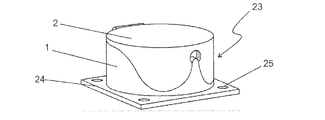
図9は、壁に取付け可能なプラグポイント23を示す。プラグポイント23は、カバー付のソケット1を有する。ソケット1は、取付板24に取り付けられる。取付板24は隅部にねじ穴25を有する。
FIG. 9 shows a
図10a〜図10cは、前面4および後面6を有するソケット1を示す。リード線7はソケット1の後面6から延びている。
10a to 10c show a
ソケット1は一体型カバー2を有する。すなわち、図10cに示すように、カバー2はソケット1の外部被覆3の一部分を形成する。外部被覆3は凹部10を含む。凹部10の縁部12は、カバー2の縁部11に対応する。カバー2は、外部被覆3の前面部周縁上のヒンジ5によってソケット1に固定される。ヒンジ5は、カバー2の開放に抵抗する力をもつ。実際には、このような力をばねによって得てもよい。すなわち、ヒンジ5はばね仕掛けである。
The
カバー2は、スリーブ18に取り囲まれる溝13を含む。部分的に重なって連続する孔14が溝13を形成する。溝13の幅を、底部に向かうにつれて減少させてもよい。溝13に尖った部分が存在しないようにして、溝13の縁を滑らかにしてもよい。しかしながら、溝の設計を器具の選択に応じて変えても構わない。
The
部分的に重なって連続する孔14をもつ溝13は、本発明のうちの保持具を形成する。使用中には、図10cで見られるように、ソケット1のカバー2は開いているが、ヒンジ5に行き渡る力がカバー2の開放に抵抗する。保持具はプラグ8および/またはリード線9を係合する。プラグ8の寸法に応じて、溝13はプラグ8の捕捉に関わってもよく、または孔14はリード線9の捕捉に関わってもよい。溝13の幅はカバーの縁に向かうにつれて増大するので、すなわち、重なって連続する孔14の直径が異なるので、溝13は直径が異なるリード線9を捕捉することができるようになる。
図11aないし図11cは、図10a〜図10cとは異なる規格に沿うソケット1およびプラグ8を示す。しかしながら、図11aないし図11cの構成は、図10aないし図10cに示す構成と類似している。
FIGS. 11a to 11c show the
図12は延長リール20を示す。延長リール20は、リールコア19およびリード線7を有する。リールコア19は、リード線7を巻き取るクランクハンドル21および延長リール20を運ぶハンドル22を備える。リールコア19の側面には、4つのカバー2付ソケット1が取り付けられている。ソケット1は、リード線7の第1の端部と電気的に接触している。リード線7の第2の端部には、プラグ8(不図示)がある。
FIG. 12 shows the
カバー2は、部分的に重なって連続する孔14をもつ溝13を含み、溝13は本発明のうちの保持具を形成する。
The
図13は、壁に取付け可能なプラグポイント23を示す。プラグポイント23は、カバー付のソケット1を有する。ソケット1は取付板24に取り付けられる。取付板24は隅部にねじ穴25を有する。
FIG. 13 shows a
カバー2は、部分的に重なって連続する孔14をもつ溝13を含み、溝13は本発明のうちの保持具を形成する。
The
図面のうち、図1aないし図6b、図8、図9、図10aないし図10c、図12および図13は、欧州規格(CEE 7/4)に沿うソケットを示す。図7aないし図7eおよび図11aないし図11cは、米国規格(NEMA 15-5)に沿うソケットを示す。しかしながら、本発明は規格を制限するものではなく、別の規格に沿うソケットに適用することも可能である。上述の変形例に加えて、説明した溝の形態を本文で述べたいかなるカバーに用いることもできる。
FIGS. 1a to 6b, 8, 9 and 10a to 10c, 12 and 13 show sockets in accordance with European standards (
Claims (9)
前記ソケットは、前面および後面を含み、さらに前記前面と前記後面の間に被覆を有し、
前記カバーは、前記ソケットの前面を覆う第1の部分および前記前面から前記後面にかけて前記被覆上に広がる第2の部分を含み、
前記カバーの第2の部分は保持具を有し、該保持具は溝を含み、該溝の底部には任意のリード線を係合可能な孔が形成され、前記溝の幅は第2の部分の縁部から前記孔に向かうにつれて減少することを特徴とする延長コード。 A lead having a first end and a second end, the first end having a socket having a cover, the second end having a plug, the cover being a cover of the cover; An extension cord attached to said socket by a hinge joint having a force resisting opening;
The socket includes a front surface and a rear surface, and further has a coating between the front surface and the rear surface;
The cover includes a second portion that spread on the coating from the first portion and the front face covers the front of the socket toward the rear surface,
The second portion of the cover has a retainer, the retainer includes a groove, and a hole is formed at the bottom of the groove so that any lead wire can be engaged with the groove . An extension cord which decreases from the edge of the portion toward the hole.
前記ソケットは、前面および後面を含み、さらに前記前面と前記後面の間に被覆を有し、
前記カバーは、前記ソケットの前面を覆う第1の部分および前記前面から前記後面にかけて前記被覆上に広がる第2の部分を含み、
前記カバーの第2の部分は保持具を有し、該保持具は溝を含み、該溝の底部には任意のリード線を係合可能な孔が形成され、前記溝の幅は第2の部分の縁部から前記孔に向かうにつれて減少することを特徴とするカバー付きのソケット。 A cover-equipped socket, wherein the cover is attached to the socket by a hinge joint having a force that resists opening of the cover,
The socket includes a front surface and a rear surface, and further has a coating between the front surface and the rear surface;
The cover includes a second portion that spread on the coating from the first portion and the front face covers the front of the socket toward the rear surface,
The second portion of the cover has a retainer, the retainer includes a groove, and a hole is formed at the bottom of the groove so that any lead wire can be engaged with the groove . A socket with a cover, characterized in that it decreases from the edge of the part towards the hole.
該カバーは前記ソケットの前面を覆う第1の部分および前記ソケットの被覆上に広がる第2の部分を含み、前記被覆は前記ソケットの前記前面と前記ソケットの後面の間に設けられ、第2の部分は前記前面から前記後面にかけて広がり、
該カバーの第2の部分は保持具を有し、該保持具は溝を含み、該溝の底部には任意のリード線を係合可能な孔が形成され、前記溝の幅は第2の部分の縁部から前記孔に向かうにつれて減少することを特徴とするソケットのカバー。 In the socket cover,
The cover further comprises a second portion that spread on the coating of the first portion and the socket which covers the front of the socket, the cover is provided between the rear surface of the front and the socket of the socket, the The portion 2 extends from the front surface to the rear surface,
The second portion of the cover has a retainer, the retainer includes a groove, and a hole is formed at a bottom portion of the groove so that any lead wire can be engaged, and the width of the groove is equal to the second. A cover for a socket, characterized in that it decreases from the edge of the part towards the hole.
Applications Claiming Priority (3)
| Application Number | Priority Date | Filing Date | Title |
|---|---|---|---|
| FIPCT/FI2015/050260 | 2015-04-15 | ||
| PCT/FI2015/050260 WO2016166401A1 (en) | 2015-04-15 | 2015-04-15 | Extension cord, socket and cover of a socket |
| PCT/FI2016/050252 WO2016166420A1 (en) | 2015-04-15 | 2016-04-15 | Extension cord, socket and cover of a socket |
Publications (2)
| Publication Number | Publication Date |
|---|---|
| JP2018514074A JP2018514074A (en) | 2018-05-31 |
| JP6638059B2 true JP6638059B2 (en) | 2020-01-29 |
Family
ID=57126957
Family Applications (1)
| Application Number | Title | Priority Date | Filing Date |
|---|---|---|---|
| JP2018505540A Active JP6638059B2 (en) | 2015-04-15 | 2016-04-15 | Extension cord, socket and socket cover |
Country Status (12)
| Country | Link |
|---|---|
| US (1) | US10193279B2 (en) |
| EP (1) | EP3284146B1 (en) |
| JP (1) | JP6638059B2 (en) |
| CN (1) | CN106797089B (en) |
| AU (1) | AU2016250039B2 (en) |
| BR (1) | BR112017021956B1 (en) |
| CA (1) | CA2982506C (en) |
| EA (1) | EA034782B1 (en) |
| ES (1) | ES2873123T3 (en) |
| MX (1) | MX2017013232A (en) |
| PL (1) | PL3284146T3 (en) |
| WO (2) | WO2016166401A1 (en) |
Families Citing this family (5)
| Publication number | Priority date | Publication date | Assignee | Title |
|---|---|---|---|---|
| US9899823B1 (en) | 2017-03-21 | 2018-02-20 | George E. Catinis | Apparatus and method for sheltering electrical cord connections |
| JP7032197B2 (en) | 2018-03-28 | 2022-03-08 | 株式会社カネカ | Connector cover |
| USD933607S1 (en) * | 2019-10-04 | 2021-10-19 | Physio-Control, Inc. | Medical device connector |
| USD931219S1 (en) * | 2019-10-04 | 2021-09-21 | Physio-Control, Inc. | Medical device connector |
| USD927426S1 (en) | 2019-10-04 | 2021-08-10 | Physio-Control, Inc. | Medical device connector |
Family Cites Families (31)
| Publication number | Priority date | Publication date | Assignee | Title |
|---|---|---|---|---|
| US4204738A (en) * | 1978-03-31 | 1980-05-27 | The Toro Company | Electrical connector retaining device |
| US4221449A (en) * | 1979-05-07 | 1980-09-09 | Shugart Jr James F | Locking device for electric cords |
| DE3327087C1 (en) * | 1983-07-27 | 1984-08-16 | Franz 8018 Grafing Lechner | Adaptor for protecting mains plugs against unauthorised apparatus use |
| JPH01265471A (en) * | 1988-04-15 | 1989-10-23 | M G S Japan Kk | Electric connection appliance |
| US5122069A (en) * | 1989-07-28 | 1992-06-16 | Amp Incorporated | Access flooring module |
| US5336107A (en) | 1993-04-26 | 1994-08-09 | Cyclops Research & Development, Inc. | Plug retention device |
| US5573420A (en) * | 1994-12-20 | 1996-11-12 | Grosswendt; Patrick J. | Electrical cord and electrical plug securer |
| US5785547A (en) * | 1996-04-19 | 1998-07-28 | The Dzyne Group, Ltd. | Electrical plug and cord strain relief and coupling device |
| US5911586A (en) | 1996-06-01 | 1999-06-15 | Wintergerst; H. Peter | System, device and method for locking and unlocking power flow to an electrical cord |
| US6080004A (en) * | 1998-03-09 | 2000-06-27 | Alert Safety Lite Products Co., Inc. | Electrical plug lock |
| US6189187B1 (en) * | 1999-09-27 | 2001-02-20 | John J. Williams | Clip for holding a pair of elongated member portions |
| FR2823603B1 (en) | 2001-04-17 | 2003-08-15 | Legrand Sa | WATERPROOF ELECTRICAL APPLIANCE |
| DE10140294A1 (en) * | 2001-08-16 | 2003-03-06 | Wilfried Kroemker Gmbh | Electric plug socket strip for medical applications, has hinged cover above plug opening and locking element for locking cover to strip when closed to prevent removal of plugs from socket(s) |
| NZ541470A (en) * | 2003-01-27 | 2006-12-22 | Dormina Uk Ltd | Improvements in or relating to safety covers for electric sockets and the like |
| US7442873B2 (en) * | 2005-02-03 | 2008-10-28 | Mccormick Sean | Environmentally protected enclosure for electrical power distributor and the like |
| US7540767B1 (en) * | 2006-08-25 | 2009-06-02 | Reliance Controls Corporation | Plug-in amp/watt power meter |
| US8242365B2 (en) * | 2006-08-29 | 2012-08-14 | The Wiremold Company | Cover for recessed electrical outlet box |
| NL1032887C2 (en) * | 2006-11-17 | 2008-10-07 | Thule Towing Systems B V | Outlet for connecting plug of e.g. trailer, with rear of towing vehicle, has upper casing comprising hinge part with lid, and light source i.e. LED, comprising light guide for illuminating portion of end surfaces of outlet |
| KR20080003766U (en) * | 2007-03-05 | 2008-09-10 | 주식회사 이엠테크 | Rain and Fall-Proof Outlet and Plug |
| US8535082B2 (en) * | 2010-02-22 | 2013-09-17 | Charles Lifson | Apparatus for providing a secure connection between different devices |
| CN201766225U (en) | 2010-08-13 | 2011-03-16 | 俞国麟 | Extension line |
| CN102157849A (en) * | 2011-03-09 | 2011-08-17 | 南通芯迎设计服务有限公司 | Simple power connector wire |
| CN202145507U (en) * | 2011-08-08 | 2012-02-15 | 浙江理工大学 | Waterproof socket |
| JP5906410B2 (en) * | 2011-09-21 | 2016-04-20 | パナソニックIpマネジメント株式会社 | Outlet |
| JP5613133B2 (en) * | 2011-10-26 | 2014-10-22 | 富士通フロンテック株式会社 | Connector holder |
| CN202363644U (en) * | 2011-12-12 | 2012-08-01 | 连潮江 | Protective box for power socket |
| CN103594869A (en) * | 2012-08-15 | 2014-02-19 | 鸿富锦精密工业(深圳)有限公司 | Power socket |
| CN202749567U (en) | 2012-08-30 | 2013-02-20 | 温岭市安通电器有限公司 | Safe socket |
| US9088087B2 (en) * | 2012-12-12 | 2015-07-21 | Hydrofarm, Inc. | Dual interchangeable electrical receptacle |
| CN203135054U (en) * | 2012-12-29 | 2013-08-14 | 吕雪峰 | Safe socket |
| CN203150847U (en) * | 2012-12-30 | 2013-08-21 | 浙江理工大学 | Winding-proof socket |
-
2015
- 2015-04-15 WO PCT/FI2015/050260 patent/WO2016166401A1/en active Application Filing
-
2016
- 2016-04-15 EP EP16779666.3A patent/EP3284146B1/en active Active
- 2016-04-15 CA CA2982506A patent/CA2982506C/en active Active
- 2016-04-15 ES ES16779666T patent/ES2873123T3/en active Active
- 2016-04-15 EA EA201792284A patent/EA034782B1/en not_active IP Right Cessation
- 2016-04-15 US US15/566,432 patent/US10193279B2/en active Active
- 2016-04-15 MX MX2017013232A patent/MX2017013232A/en unknown
- 2016-04-15 WO PCT/FI2016/050252 patent/WO2016166420A1/en active Application Filing
- 2016-04-15 PL PL16779666T patent/PL3284146T3/en unknown
- 2016-04-15 AU AU2016250039A patent/AU2016250039B2/en active Active
- 2016-04-15 BR BR112017021956-5A patent/BR112017021956B1/en active IP Right Grant
- 2016-04-15 JP JP2018505540A patent/JP6638059B2/en active Active
- 2016-04-15 CN CN201680002428.7A patent/CN106797089B/en active Active
Also Published As
| Publication number | Publication date |
|---|---|
| ES2873123T3 (en) | 2021-11-03 |
| JP2018514074A (en) | 2018-05-31 |
| EA201792284A1 (en) | 2018-05-31 |
| AU2016250039A1 (en) | 2017-11-30 |
| US10193279B2 (en) | 2019-01-29 |
| EP3284146A4 (en) | 2018-10-24 |
| PL3284146T3 (en) | 2021-10-25 |
| AU2016250039B2 (en) | 2018-12-13 |
| BR112017021956B1 (en) | 2023-04-25 |
| EA034782B1 (en) | 2020-03-20 |
| CN106797089B (en) | 2020-07-10 |
| WO2016166401A1 (en) | 2016-10-20 |
| WO2016166420A1 (en) | 2016-10-20 |
| CN106797089A (en) | 2017-05-31 |
| US20180159274A1 (en) | 2018-06-07 |
| BR112017021956A2 (en) | 2018-07-10 |
| EP3284146A1 (en) | 2018-02-21 |
| EP3284146B1 (en) | 2021-03-24 |
| CA2982506C (en) | 2019-08-06 |
| CA2982506A1 (en) | 2016-10-20 |
| MX2017013232A (en) | 2018-08-15 |
Similar Documents
| Publication | Publication Date | Title |
|---|---|---|
| JP6638059B2 (en) | Extension cord, socket and socket cover | |
| US8491318B2 (en) | Thin socket | |
| EP3118964A1 (en) | Electronic cigarette charger | |
| US9257857B2 (en) | Cable positioning device and charger using same | |
| TWM498102U (en) | Wire stripper | |
| US6095849A (en) | Structure of flat plug | |
| US7494350B1 (en) | Electrical device with a retractable plug | |
| US10348030B1 (en) | Socket connector | |
| US7001199B1 (en) | Electrical connection | |
| US6547600B2 (en) | Engaging structure for electrical wires of a plug | |
| JP3189714U (en) | plug | |
| US20050183915A1 (en) | Device for accommodating wire storage structure | |
| KR101820143B1 (en) | Wiring connector | |
| JP2014089913A (en) | Protective cover | |
| JP4860524B2 (en) | Coaxial cable connector | |
| JPH027148B2 (en) | ||
| KR101830436B1 (en) | Wiring connector | |
| KR101830435B1 (en) | Wiring connector | |
| US9941618B2 (en) | Electrical connector | |
| JP2018041571A (en) | Waterproof terminal | |
| TWM580276U (en) | Electric wire insertion device for socket | |
| WO2021174743A1 (en) | Socket | |
| JP2016032412A (en) | Protector for wiring harness | |
| CN106303782A (en) | There is the earphone of the passage for wire management | |
| TWM496285U (en) | Cable adaptor |
Legal Events
| Date | Code | Title | Description |
|---|---|---|---|
| A521 | Request for written amendment filed |
Free format text: JAPANESE INTERMEDIATE CODE: A523 Effective date: 20171030 |
|
| A621 | Written request for application examination |
Free format text: JAPANESE INTERMEDIATE CODE: A621 Effective date: 20171030 |
|
| RD01 | Notification of change of attorney |
Free format text: JAPANESE INTERMEDIATE CODE: A7426 Effective date: 20180530 |
|
| RD02 | Notification of acceptance of power of attorney |
Free format text: JAPANESE INTERMEDIATE CODE: A7422 Effective date: 20180530 |
|
| A521 | Request for written amendment filed |
Free format text: JAPANESE INTERMEDIATE CODE: A821 Effective date: 20180530 |
|
| A977 | Report on retrieval |
Free format text: JAPANESE INTERMEDIATE CODE: A971007 Effective date: 20180912 |
|
| A131 | Notification of reasons for refusal |
Free format text: JAPANESE INTERMEDIATE CODE: A131 Effective date: 20181016 |
|
| A601 | Written request for extension of time |
Free format text: JAPANESE INTERMEDIATE CODE: A601 Effective date: 20190116 |
|
| A521 | Request for written amendment filed |
Free format text: JAPANESE INTERMEDIATE CODE: A523 Effective date: 20190315 |
|
| A131 | Notification of reasons for refusal |
Free format text: JAPANESE INTERMEDIATE CODE: A131 Effective date: 20190618 |
|
| A521 | Request for written amendment filed |
Free format text: JAPANESE INTERMEDIATE CODE: A523 Effective date: 20190917 |
|
| TRDD | Decision of grant or rejection written | ||
| A01 | Written decision to grant a patent or to grant a registration (utility model) |
Free format text: JAPANESE INTERMEDIATE CODE: A01 Effective date: 20191210 |
|
| A61 | First payment of annual fees (during grant procedure) |
Free format text: JAPANESE INTERMEDIATE CODE: A61 Effective date: 20191223 |
|
| R150 | Certificate of patent or registration of utility model |
Ref document number: 6638059 Country of ref document: JP Free format text: JAPANESE INTERMEDIATE CODE: R150 |
|
| R250 | Receipt of annual fees |
Free format text: JAPANESE INTERMEDIATE CODE: R250 |
|
| R250 | Receipt of annual fees |
Free format text: JAPANESE INTERMEDIATE CODE: R250 |
|
| R250 | Receipt of annual fees |
Free format text: JAPANESE INTERMEDIATE CODE: R250 |