[go: up one dir, main page]

JP7032197B2 - Connector cover - Google Patents

Connector cover Download PDF

Info

Publication number
JP7032197B2
JP7032197B2 JP2018062832A JP2018062832A JP7032197B2 JP 7032197 B2 JP7032197 B2 JP 7032197B2 JP 2018062832 A JP2018062832 A JP 2018062832A JP 2018062832 A JP2018062832 A JP 2018062832A JP 7032197 B2 JP7032197 B2 JP 7032197B2
Authority
JP
Japan
Prior art keywords
connector
main body
cover
body portion
cable
Prior art date
Legal status (The legal status is an assumption and is not a legal conclusion. Google has not performed a legal analysis and makes no representation as to the accuracy of the status listed.)
Active
Application number
JP2018062832A
Other languages
Japanese (ja)
Other versions
JP2019175692A (en
Inventor
裕之 山口
Current Assignee (The listed assignees may be inaccurate. Google has not performed a legal analysis and makes no representation or warranty as to the accuracy of the list.)
Kaneka Corp
Original Assignee
Kaneka Corp
Priority date (The priority date is an assumption and is not a legal conclusion. Google has not performed a legal analysis and makes no representation as to the accuracy of the date listed.)
Filing date
Publication date
Application filed by Kaneka Corp filed Critical Kaneka Corp
Priority to JP2018062832A priority Critical patent/JP7032197B2/en
Publication of JP2019175692A publication Critical patent/JP2019175692A/en
Application granted granted Critical
Publication of JP7032197B2 publication Critical patent/JP7032197B2/en
Active legal-status Critical Current
Anticipated expiration legal-status Critical

Links

Images

Classifications

    • YGENERAL TAGGING OF NEW TECHNOLOGICAL DEVELOPMENTS; GENERAL TAGGING OF CROSS-SECTIONAL TECHNOLOGIES SPANNING OVER SEVERAL SECTIONS OF THE IPC; TECHNICAL SUBJECTS COVERED BY FORMER USPC CROSS-REFERENCE ART COLLECTIONS [XRACs] AND DIGESTS
    • Y02TECHNOLOGIES OR APPLICATIONS FOR MITIGATION OR ADAPTATION AGAINST CLIMATE CHANGE
    • Y02EREDUCTION OF GREENHOUSE GAS [GHG] EMISSIONS, RELATED TO ENERGY GENERATION, TRANSMISSION OR DISTRIBUTION
    • Y02E10/00Energy generation through renewable energy sources
    • Y02E10/50Photovoltaic [PV] energy

Landscapes

  • Casings For Electric Apparatus (AREA)
  • Details Of Connecting Devices For Male And Female Coupling (AREA)
  • Photovoltaic Devices (AREA)
  • Cable Accessories (AREA)

Description

本発明は、コネクタカバーに関するものである。 The present invention relates to a connector cover.

従来、電気機器の電気的な接続にコネクタ付きケーブルが用いられている。例えば、特許文献1では、隣り合う太陽電池パネルが、該太陽電池パネルに接続されたケーブルのコネクタ同士を接続することによって電気的に接続されている。 Conventionally, a cable with a connector has been used for electrical connection of an electric device. For example, in Patent Document 1, adjacent solar cell panels are electrically connected by connecting the connectors of cables connected to the solar cell panels.

特開2009-302560号公報Japanese Unexamined Patent Publication No. 2009-302560

ところで、施工時の接続不足や経年の使用によってコネクタ同士の接続が緩むことがある。コネクタ同士の接続が緩むと、導通不良によって電力量が低下すると共に、抵抗の増加によって高温に発熱するおそれがある。 By the way, the connection between connectors may be loosened due to insufficient connection during construction or long-term use. If the connection between the connectors is loosened, the amount of electric power may decrease due to poor continuity, and heat may be generated at a high temperature due to an increase in resistance.

本発明は、かかる点に鑑みてなされたものであり、その目的は、電気機器を接続するケーブルのコネクタ同士の接続の緩みを抑制する着脱容易な手段を提供することにある。 The present invention has been made in view of this point, and an object of the present invention is to provide an easy-to-detach means for suppressing loosening of connections between connectors of cables for connecting electric devices.

本発明は、互いに接続される第1ケーブルに繋がる第1コネクタと第2ケーブルに繋がる第2コネクタとを覆うコネクタカバーであって、不燃材料で開閉可能な筒状に形成され、閉状態において互いに接続された上記第1コネクタ及び上記第2コネクタの側面全周を一体的に覆う本体部と、上記本体部の上記第1ケーブル側の一端部から該本体部の内側に突出し、上記第1コネクタに当接することによって該第1コネクタの上記第2コネクタとの接続が解除される方向への移動を規制する第1規制部と、上記本体部の上記第2ケーブル側の他端部から該本体部の内側に突出し、上記第2コネクタに当接することによって該第2コネクタの上記第1コネクタとの接続が解除される方向への移動を規制する第2規制部とを含み、上記本体部は、開状態の際に該本体部が閉状態になるように該本体部を付勢する弾性力、又は閉状態の際に上記本体部が開状態になるように該本体部を付勢する弾性力が該本体部に作用するように構成されているものである。 INDUSTRIAL APPLICABILITY The present invention is a connector cover that covers a first connector connected to a first cable connected to each other and a second connector connected to a second cable. The main body that integrally covers the entire side surface of the first connector and the second connector that are connected, and the first connector that protrudes inward from one end of the main body on the first cable side. From the other end of the main body portion on the second cable side to the first restricting portion that regulates the movement of the first connector in the direction in which the connection with the second connector is released by abutting against the main body. The main body portion includes a second restricting portion that projects inward of the portion and restricts the movement of the second connector in a direction in which the connection with the first connector is released by abutting on the second connector. , The elastic force that urges the main body so that the main body is closed when the main body is open, or the elasticity that urges the main body so that the main body is open when the main body is closed. The force is configured to act on the main body portion.

また、他の発明は、互いに接続される第1ケーブルに繋がる第1コネクタと第2ケーブルに繋がる第2コネクタとを覆うコネクタカバーであって、不燃材料で形成され、互いに接続された上記第1コネクタ及び上記第2コネクタの側面全周を一体的に覆う筒状の第1本体部と、上記第1ケーブルは挿通可能で上記第1コネクタは挿通不能な第1挿通孔が形成されて上記第1本体部の上記第1ケーブル側の端面を覆う第1遮蔽部とを有する第1部材と、不燃材料で形成され、上記第1本体部にスライド可能に外嵌される筒状の第2本体部と、上記第2ケーブルは挿通可能で上記第2コネクタは挿通不能な第2挿通孔が形成されて上記第2本体部の上記第2ケーブル側の端面を覆う第2遮蔽部と、上記第1部材と係合して上記第2本体部の上記第1本体部に対するスライドを規制する係合部とを有する第2部材とを含み、上記第1遮蔽部は、上記第1コネクタに当接することによって該第1コネクタの上記第2コネクタとの接続が解除される方向への移動を規制するように構成され、上記第2遮蔽部は、上記第2コネクタに当接することによって該第2コネクタの上記第1コネクタとの接続が解除される方向への移動を規制するように構成されているものである。 Another invention is a connector cover that covers a first connector connected to a first cable connected to each other and a second connector connected to a second cable, and is formed of a non-combustible material and connected to each other. A tubular first main body that integrally covers the entire side surface of the connector and the second connector, and a first insertion hole that allows the first cable to be inserted but cannot be inserted into the first connector are formed. 1 A tubular second main body formed of a non-combustible material and slidably fitted onto the first main body portion, and a first member having a first shielding portion covering the end surface of the first main body portion on the first cable side. A second shielding portion, which is formed with a second insertion hole through which the second cable can be inserted but cannot be inserted through the second connector, and covers the end surface of the second main body on the second cable side, and the second shield. The first shielding portion abuts on the first connector, including a second member having an engaging portion that engages with one member and restricts the sliding of the second main body portion with respect to the first main body portion. This is configured to restrict the movement of the first connector in the direction in which the connection with the second connector is released, and the second shielding portion abuts on the second connector to cause the second connector. It is configured to restrict movement in the direction in which the connection with the first connector is released.

本発明のコネクタカバーは、着脱容易であり、電気機器を接続するケーブルのコネクタ同士の接続の緩みが抑制される。 The connector cover of the present invention is easy to put on and take off, and loosening of the connection between the connectors of the cables connecting the electric devices is suppressed.

図1は、実施形態1のコネクタカバーの設置状態を示す模式図である。FIG. 1 is a schematic view showing an installed state of the connector cover of the first embodiment. 図2は、実施形態1のコネクタカバーがコネクタ接続部に設置された状態を示す斜視図である。FIG. 2 is a perspective view showing a state in which the connector cover of the first embodiment is installed in the connector connection portion. 図3は、実施形態1のコネクタカバーの開状態を示す斜視図である。FIG. 3 is a perspective view showing an open state of the connector cover of the first embodiment. 図4は、実施形態1のコネクタカバーを構成する板金の展開図である。FIG. 4 is a developed view of the sheet metal constituting the connector cover of the first embodiment.


図5は、実施形態1のコネクタカバーを保持部部分で切断した断面図である。FIG. 5 is a cross-sectional view of the connector cover of the first embodiment cut at the holding portion. 図6は、実施形態2のコネクタカバーがコネクタ接続部に設置された状態を示す斜視図である。FIG. 6 is a perspective view showing a state in which the connector cover of the second embodiment is installed at the connector connection portion. 図7は、実施形態2のコネクタカバーの第1カバー本体と第2カバー本体の分解斜視図である。FIG. 7 is an exploded perspective view of the first cover main body and the second cover main body of the connector cover of the second embodiment. 図8は、実施形態2のコネクタカバーの閉状態を示す側面図である。FIG. 8 is a side view showing a closed state of the connector cover of the second embodiment. 図9は、実施形態2のコネクタカバーの開状態を示す側面図である。FIG. 9 is a side view showing an open state of the connector cover of the second embodiment. 図10は、実施形態3のコネクタカバーがコネクタ接続部に設置された状態を示す斜視図である。FIG. 10 is a perspective view showing a state in which the connector cover of the third embodiment is installed in the connector connection portion. 図11は、実施形態3のコネクタカバーの分解斜視図である。FIG. 11 is an exploded perspective view of the connector cover of the third embodiment. 図12は、実施形態3のコネクタカバーの設置前の状態を示す模式図である。FIG. 12 is a schematic view showing a state before installation of the connector cover of the third embodiment.

以下、本発明の実施形態を図面に基づいて詳細に説明する。以下の実施形態は、本質的に好ましい例示に過ぎず、本発明、その適用物、あるいはその用途の範囲を制限することを意図するものではない。 Hereinafter, embodiments of the present invention will be described in detail with reference to the drawings. The following embodiments are merely preferred embodiments and are not intended to limit the scope of the invention, its applications, or its uses.

以下の実施形態1~3では、図1に模式的に示すように、本発明に係るコネクタカバーの一例として、隣り合う太陽電池パネルP(電気機器)を電気的に接続する第1ケーブルC1と第2ケーブルC2の第1コネクタC11と第2コネクタC12とを一体的に覆うコネクタカバー10について説明する。 In the following embodiments 1 to 3, as schematically shown in FIG. 1, as an example of the connector cover according to the present invention, the first cable C1 for electrically connecting the adjacent solar cell panels P (electrical devices) is used. The connector cover 10 that integrally covers the first connector C11 and the second connector C12 of the second cable C2 will be described.

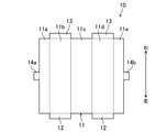
図1に示すように、一列に並べて設置された複数の太陽電池パネルPのそれぞれには、第1ケーブルC1と第2ケーブルC2とが接続されている。第1ケーブルC1と第2ケーブルC2とは、各太陽電池パネルPの裏面(受光面と逆側の面)に設けられた端子ボックスJBに収容された端子に接続されている。各太陽電池パネルPの第1ケーブルC1は、隣の太陽電池パネルPまで延び、端部に設けられた第1コネクタC11が、隣の太陽電池パネルPの第2ケーブルC2の端部に設けられた第2コネクタC12に接続されている。本実施形態1では、コネクタカバー10は、このように隣り合う太陽電池パネルPの一方側の第1ケーブルC1の第1コネクタC11と他方側の太陽電池パネルPの第2ケーブルC2の第2コネクタC12との接続部分を覆っている。 As shown in FIG. 1, a first cable C1 and a second cable C2 are connected to each of a plurality of solar cell panels P installed side by side in a row. The first cable C1 and the second cable C2 are connected to terminals housed in a terminal box JB provided on the back surface (the surface opposite to the light receiving surface) of each solar cell panel P. The first cable C1 of each solar cell panel P extends to the adjacent solar cell panel P, and the first connector C11 provided at the end is provided at the end of the second cable C2 of the adjacent solar cell panel P. It is connected to the second connector C12. In the first embodiment, the connector cover 10 has the first connector C11 of the first cable C1 on one side of the adjacent solar cell panels P and the second connector of the second cable C2 of the solar cell panel P on the other side. It covers the connection part with C12.

第1コネクタC11と第2コネクタC12は、それぞれケーブル側の端部を基端部、逆側の端部を先端部とすると、先端部に互いに係合する係合部が形成されている。本実施形態では、第1コネクタC11の先端部には凸部が形成され、第2コネクタC12の先端部には第1コネクタC11の凸部が嵌まり込む凹部が形成されている。第1コネクタC11と第2コネクタC12とは、第1コネクタC11の凸部を第2コネクタC12の凹部に嵌め込むことによって互いに接続され、第1コネクタC11の凸部を第2コネクタC12の凹部から引き抜くことによって互いの接続が解除される。なお、第1コネクタC11と第2コネクタC12の係合部の形状は上述の形状に限られず、いかなるものであってもよい。例えば、第1コネクタC11と第2コネクタC12の両方の先端部に凸部と凹部とが形成されていてもよい。 The first connector C11 and the second connector C12 have an engaging portion that engages with each other, assuming that the end on the cable side is the base end and the end on the opposite side is the tip. In the present embodiment, a convex portion is formed at the tip end portion of the first connector C11, and a concave portion into which the convex portion of the first connector C11 is fitted is formed at the tip end portion of the second connector C12. The first connector C11 and the second connector C12 are connected to each other by fitting the convex portion of the first connector C11 into the concave portion of the second connector C12, and the convex portion of the first connector C11 is connected to the concave portion of the second connector C12. By pulling it out, the connection with each other is released. The shape of the engaging portion between the first connector C11 and the second connector C12 is not limited to the above-mentioned shape, and may be any shape. For example, a convex portion and a concave portion may be formed at the tip portions of both the first connector C11 and the second connector C12.

《実施形態1》
以下、実施形態1のコネクタカバー10について図2~図5を用いて説明する。
<< Embodiment 1 >>
Hereinafter, the connector cover 10 of the first embodiment will be described with reference to FIGS. 2 to 5.

なお、以下では、便宜上、図2に矢印で示すように、紙面の右方向を前方、紙面の左方向を後方、紙面の上方向を上方、紙面の下方向を下方、紙面の左斜め下方向を左方、紙面の右斜め上方向を右方として説明する。また、前後方向をX方向、上下方向をY方向、左右方向をZ方向という。なお、Z方向は、第1コネクタC11と第2コネクタC12との着脱方向(第1コネクタC11及び第2コネクタC12の接続時の配列方向)となる。 In the following, for convenience, as shown by arrows in FIG. 2, the right direction of the paper surface is forward, the left direction of the paper surface is rear, the upper direction of the paper surface is upward, the lower direction of the paper surface is downward, and the diagonally downward direction to the left of the paper surface. Will be described as the left side, and diagonally upward to the right of the paper as the right side. Further, the front-back direction is referred to as an X direction, the up-down direction is referred to as a Y direction, and the left-right direction is referred to as a Z direction. The Z direction is the attachment / detachment direction between the first connector C11 and the second connector C12 (the arrangement direction when the first connector C11 and the second connector C12 are connected).

-コネクタカバーの構成-
図2及び図3に示すように、コネクタカバー10は、本体部11と、2つの左側規制部12と、2つの右側規制部13と、保持部14とを備えている。本体部11と、2つの左側規制部12と、2つの右側規制部13と、保持部14とは、一枚の板金を折り曲げることによって形成されている。
-Connector cover configuration-
As shown in FIGS. 2 and 3, the connector cover 10 includes a main body portion 11, two left side regulating portions 12, two right side regulating portions 13, and a holding portion 14. The main body portion 11, the two left side regulating portions 12, the two right side regulating portions 13, and the holding portion 14 are formed by bending one sheet metal.

[本体部]
本体部11は、図4に示す板金に、谷折り線(図4の破線)で折り曲げる折り曲げ加工を施すことによってXY方向の断面が略矩形の筒状に形成されている。本体部11は、X方向及びY方向の長さに対してZ方向の長さが長い筒状に形成されている。また、本体部11は、互いに接続された第1コネクタC11及び第2コネクタC12の側面全周(着脱方向に沿う前面、上面、後面及び下面からなる外周面)を一体的に覆うことができる大きさに形成されている。つまり、本体部11は、X方向、Y方向及びZ方向の寸法が、それぞれ第1コネクタC11及び第2コネクタC12のX方向、Y方向及びZ方向の寸法よりも大きくなるように形成されている。
[Main body]
The main body 11 is formed in a cylindrical shape having a substantially rectangular cross section in the XY direction by subjecting the sheet metal shown in FIG. 4 to a bending process of bending along a valley fold line (broken line in FIG. 4). The main body portion 11 is formed in a cylindrical shape having a length in the Z direction longer than the length in the X direction and the Y direction. Further, the main body portion 11 has a size capable of integrally covering the entire circumference of the side surface of the first connector C11 and the second connector C12 connected to each other (the outer peripheral surface composed of the front surface, the upper surface, the rear surface and the lower surface along the attachment / detachment direction). It is formed on the connector. That is, the main body portion 11 is formed so that the dimensions in the X direction, the Y direction, and the Z direction are larger than the dimensions in the X direction, the Y direction, and the Z direction of the first connector C11 and the second connector C12, respectively. ..

図2及び図3に示すように、本体部11は、前上面部11aと、上面部11bと、後面部11cと、下面部11dと、前下面部11eとを有している。前上面部11aと上面部11bと後面部11cと下面部11dと前下面部11eとは、いずれも図4に示す板金の矩形状の一部分によって形成される。前上面部11aと上面部11bと下面部11dと前下面部11eとは、平板状に形成されている。一方、後面部11cは、プレス加工によって湾曲形状に形成されている。 As shown in FIGS. 2 and 3, the main body portion 11 has a front upper surface portion 11a, an upper surface portion 11b, a rear surface portion 11c, a lower surface portion 11d, and a front lower surface portion 11e. The front upper surface portion 11a, the upper surface portion 11b, the rear surface portion 11c, the lower surface portion 11d, and the front lower surface portion 11e are all formed by a rectangular portion of the sheet metal shown in FIG. The front upper surface portion 11a, the upper surface portion 11b, the lower surface portion 11d, and the front lower surface portion 11e are formed in a flat plate shape. On the other hand, the rear surface portion 11c is formed into a curved shape by press working.

後面部11cは、例えば、図4に示す板金に折り曲げ加工を行う前に、板金の後面部11cとなる部分に対してプレス加工を施すことによって湾曲形状に形成されている。後面部11cは、上下方向(Y方向)の中央部分が両端部(上端部及び下端部)よりも筒状の本体部11の内側に膨出するように湾曲している。後面部11cは、このように湾曲形状に形成されることにより、本体部11が閉状態の際に該本体部11が開状態になるように該本体部11を付勢する板ばね部となる。 The rear surface portion 11c is formed into a curved shape by, for example, pressing a portion of the sheet metal to be the rear surface portion 11c before bending the sheet metal shown in FIG. The rear surface portion 11c is curved so that the central portion in the vertical direction (Y direction) bulges inward of the cylindrical main body portion 11 from both end portions (upper end portion and lower end portion). The rear surface portion 11c is formed in such a curved shape to serve as a leaf spring portion that urges the main body portion 11 so that the main body portion 11 is in the open state when the main body portion 11 is in the closed state. ..

具体的には、本体部11は、図3及び図5に示すように、外力が何ら作用しない場合、前上面部11aの下端と前下面部11eとの上端とが離れた開状態となる。一方、本体部11の上面部11bに、該上面部11bを下面部11d側に押圧する力を作用させると、本体部11は、前上面部11aの下端と前下面部11eとの上端とが近づき、やがて前上面部11aの下端と前下面部11eとの上端とが当接した閉状態(図5の二点鎖線で示す状態)となる。このとき、後面部11cは、上面部11bに引っ張られて弾性変形し、湾曲面の曲率が徐々に小さくなり、閉状態では平板に近い形状となる。 Specifically, as shown in FIGS. 3 and 5, when no external force acts, the main body 11 is in an open state in which the lower end of the front upper surface portion 11a and the upper end of the front lower surface portion 11e are separated from each other. On the other hand, when a force for pressing the upper surface portion 11b toward the lower surface portion 11d is applied to the upper surface portion 11b of the main body portion 11, the main body portion 11 has the lower end of the front upper surface portion 11a and the upper end of the front lower surface portion 11e. As it approaches, the lower end of the front upper surface portion 11a and the upper end of the front lower surface portion 11e are in contact with each other (the state shown by the two-dot chain line in FIG. 5). At this time, the rear surface portion 11c is elastically deformed by being pulled by the upper surface portion 11b, the curvature of the curved surface gradually decreases, and the shape becomes close to a flat plate in the closed state.

上述のような後面部11cの弾性変形により、本体部11が閉状態の際に、本体部11には、後面部11c(板ばね部)が元の形状に戻ろうとする復元力(弾性力)が作用し、本体部11は、開状態になるように付勢される。つまり、本体部11を、開状態から上面部11bを手で押さえて閉状態にした後、その手を離して該上面部11bに作用させていた力を取り除くと、本体部11は、後面部11c(板ばね部)の復元力(弾性力)によって上面部11bが持ち上げられ、すぐに元の開状態となる。 Due to the elastic deformation of the rear surface portion 11c as described above, when the main body portion 11 is in the closed state, the restoring force (elastic force) at which the rear surface portion 11c (leaf spring portion) tries to return to the original shape is applied to the main body portion 11. Acts, and the main body 11 is urged to be in an open state. That is, when the main body portion 11 is closed by pressing the upper surface portion 11b by hand from the open state and then releasing the hand to remove the force acting on the upper surface portion 11b, the main body portion 11 becomes the rear surface portion. The upper surface portion 11b is lifted by the restoring force (elastic force) of the 11c (leaf spring portion), and immediately returns to the original open state.

[規制部]
2つの左側規制部12は、第1コネクタC11及び第2コネクタC12の一方のコネクタに当接することによって該一方のコネクタの他方のコネクタとの接続が解除される方向への移動を規制するものである。本実施形態1では、2つの左側規制部12は、本体部11内において左側に設けられる第1コネクタC11に当接することによって第1コネクタC11の第2コネクタC12との接続が解除される左方への移動を規制する。
[Regulatory Department]
The two left side restricting portions 12 restrict the movement of one connector in the direction in which the connection with the other connector is released by abutting on one of the connectors of the first connector C11 and the second connector C12. be. In the first embodiment, the two left side restricting portions 12 are left to be disconnected from the second connector C12 of the first connector C11 by abutting on the first connector C11 provided on the left side in the main body portion 11. Regulate movement to.

具体的には、図2及び図3に示すように、2つの左側規制部12は、本体部11のZ方向において左側端部(第1コネクタC11及び第2コネクタC12の着脱方向において第1ケーブルC1側の一端部)からそれぞれ該本体部11の内側に突出している。本実施形態では、2つの左側規制部12は、本体部11の上面部11bの左側端部から該本体部11の内側に突出する上側の左側規制部12と、本体部11の下面部11dの左側端部から該本体部11の内側に突出する下側の左側規制部12とによって構成されている。 Specifically, as shown in FIGS. 2 and 3, the two left side restricting portions 12 are the left end portions in the Z direction of the main body portion 11 (the first cable in the attachment / detachment direction of the first connector C11 and the second connector C12). It protrudes inward from the main body 11 from one end on the C1 side). In the present embodiment, the two left side restricting portions 12 are the upper left side regulating portion 12 protruding inward from the left side end portion of the upper surface portion 11b of the main body portion 11 and the lower surface portion 11d of the main body portion 11. It is composed of a lower left side regulating portion 12 projecting from the left side end portion to the inside of the main body portion 11.

2つの左側規制部12は、図4に示す板金の本体部11を構成する部分に連続して該本体部11を構成する部分に対して折り曲げられた板状片部によって形成されている。具体的には、上側の左側規制部12は、図4に示す板金の上面部11bとなる部分の左側端部(図4では下側端部)に連続する矩形状の板状片部を上面部11bに対して折り曲げることによって形成されている。下側の左側規制部12は、図4に示す板金の下面部11dとなる部分の左側端部(図4では下側端部)に連続する矩形状の板状片部を下面部11dに対して折り曲げることによって形成されている。 The two left side restricting portions 12 are formed by a plate-shaped piece portion that is continuously bent with respect to the portion constituting the main body portion 11 of the sheet metal shown in FIG. Specifically, the upper left side regulating portion 12 has a rectangular plate-shaped piece portion on the upper surface, which is continuous with the left end portion (lower end portion in FIG. 4) of the portion to be the upper surface portion 11b of the sheet metal shown in FIG. It is formed by bending the portion 11b. The lower left side restricting portion 12 has a rectangular plate-shaped piece continuous with the left end portion (lower end portion in FIG. 4) of the portion serving as the lower surface portion 11d of the sheet metal shown in FIG. 4 with respect to the lower surface portion 11d. It is formed by bending it.

なお、2つの左側規制部12は、本実施形態では、等しい大きさの矩形状に形成されているが、本体部11内において左側に設けられる第1コネクタC11に当接して該第1コネクタC11の左方への移動を規制できるものであれば、いかなる大きさ、形状であってもよい。2つの左側規制部12は、一方が他方より大きいものであってもよく、矩形状以外の形状であってもよい。また、左側規制部12は、1つだけ設けられていてもよく、3つ以上設けられていてもよい。 In the present embodiment, the two left side restricting portions 12 are formed in a rectangular shape having the same size, but the first connector C11 abuts on the first connector C11 provided on the left side in the main body portion 11. It may be of any size and shape as long as it can regulate the movement of the to the left. One of the two left side restricting portions 12 may be larger than the other, and may have a shape other than a rectangular shape. Further, only one left side regulating unit 12 may be provided, or three or more may be provided.

2つの右側規制部13は、第1コネクタC11及び第2コネクタC12の一方のコネクタに当接することによって該一方のコネクタの他方のコネクタとの接続が解除される方向への移動を規制するものである。本実施形態1では、2つの右側規制部13は、本体部11内において右側に設けられる第2コネクタC12に当接することによって第2コネクタC12の第1コネクタC11との接続が解除される右方への移動を規制する。 The two right-side regulating units 13 regulate the movement of one connector in the direction in which the connection with the other connector is released by abutting on one of the connectors of the first connector C11 and the second connector C12. be. In the first embodiment, the two right-side restricting portions 13 abut on the second connector C12 provided on the right side in the main body portion 11 to disconnect the second connector C12 from the first connector C11 on the right side. Regulate movement to.

具体的には、図2及び図3に示すように、2つの右側規制部13は、本体部11のZ方向において右側端部(第1コネクタC11及び第2コネクタC12の着脱方向において第2ケーブルC2側の他端部)からそれぞれ該本体部11の内側に突出している。本実施形態では、2つの右側規制部13は、本体部11の上面部11bの右側端部から該本体部11の内側に突出する上側の右側規制部13と、本体部11の下面部11dの右側端部から該本体部11の内側に突出する下側の右側規制部13とによって構成されている。 Specifically, as shown in FIGS. 2 and 3, the two right-side regulating portions 13 have the right end portion in the Z direction of the main body portion 11 (the second cable in the attachment / detachment direction of the first connector C11 and the second connector C12). The other end on the C2 side) protrudes inward of the main body 11. In the present embodiment, the two right-side regulating portions 13 are the upper right-side regulating portion 13 projecting inward from the right-hand end portion of the upper surface portion 11b of the main body portion 11 and the lower surface portion 11d of the main body portion 11. It is composed of a lower right side regulating portion 13 projecting from the right end portion to the inside of the main body portion 11.

2つの右側規制部13は、図4に示す板金の本体部11を構成する部分に連続して該本体部11を構成する部分に対して折り曲げられた板状片部によって形成されている。具体的には、上側の右側規制部13は、図4に示す板金の上面部11bとなる部分の右側端部(図4では上側端部)に連続する矩形状の板状片部を上面部11bに対して折り曲げることによって形成されている。下側の右側規制部13は、図4に示す板金の下面部11dとなる部分の右側端部(図4では上側端部)に連続する矩形状の板状片部を下面部11dに対して折り曲げることによって形成されている。 The two right-side regulating portions 13 are formed by a plate-shaped piece portion that is continuously bent with respect to the portion constituting the main body portion 11 of the sheet metal shown in FIG. Specifically, the upper right side regulating portion 13 has a rectangular plate-shaped piece portion continuous with the right end portion (upper end portion in FIG. 4) of the portion to be the upper surface portion 11b of the sheet metal shown in FIG. It is formed by bending with respect to 11b. The lower right side restricting portion 13 has a rectangular plate-shaped piece continuous with the right end portion (upper end portion in FIG. 4) of the portion of the sheet metal shown in FIG. 4, which is the lower surface portion 11d, with respect to the lower surface portion 11d. It is formed by folding.

なお、2つの右側規制部13は、本実施形態では、等しい大きさの矩形状に形成されているが、本体部11内において右側に設けられる第2コネクタC12に当接して該第2コネクタC12の右方への移動を規制できるものであれば、いかなる大きさ、形状であってもよい。2つの右側規制部13は、一方が他方より大きいものであってもよく、矩形状以外の形状であってもよい。また、右側規制部13は、1つだけ設けられていてもよく、3つ以上設けられていてもよい。 In the present embodiment, the two right-side regulating portions 13 are formed in a rectangular shape having the same size, but are in contact with the second connector C12 provided on the right side in the main body portion 11, and the second connector C12 is in contact with the second connector C12. It may be of any size and shape as long as it can regulate the movement of the to the right. One of the two right-side regulating portions 13 may be larger than the other, and may have a shape other than a rectangular shape. Further, only one right-side regulating unit 13 may be provided, or three or more may be provided.

本実施形態1では、左側規制部12と右側規制部13とは、Z方向、即ち、第1コネクタC11及び第2コネクタC12の着脱方向(配列方向)において対向する位置に設けられている。また、左側規制部12と右側規制部13とは、Z方向の間隔が、接続状態にある第1コネクタC11及び第2コネクタC12のZ方向の長さより僅かに大きくなるように形成されている。左側規制部12と右側規制部13とがこのような間隔で設けられることにより、接続状態にある第1コネクタC11及び第2コネクタC12を容易に本体部11内に収容することができる。また、本体部11内において接続状態にある第1コネクタC11及び第2コネクタC12に接続が解除される(引き離す)力、具体的には、第1コネクタC11に左向きの力、第2コネクタC12に右向きの力が作用しても、第1コネクタC11は左側規制部12(第1規制部)に当接することによって左方への移動が規制され、第2コネクタC12は右側規制部13(第2規制部)に当接することによって右方への移動が規制される。つまり、左側規制部12と右側規制部13とが上述のような間隔で設けられることにより、本体部11内に収容された接続状態にある第1コネクタC11及び第2コネクタC12の接続の緩みが抑制される。 In the first embodiment, the left side regulating unit 12 and the right side regulating unit 13 are provided at positions facing each other in the Z direction, that is, in the attachment / detachment direction (arrangement direction) of the first connector C11 and the second connector C12. Further, the left side regulating portion 12 and the right side regulating portion 13 are formed so that the distance in the Z direction is slightly larger than the length of the first connector C11 and the second connector C12 in the connected state in the Z direction. By providing the left side regulating portion 12 and the right side regulating portion 13 at such a distance, the first connector C11 and the second connector C12 in the connected state can be easily accommodated in the main body portion 11. Further, a force for disconnecting (pulling) the connection to the first connector C11 and the second connector C12 which are connected in the main body portion 11, specifically, a force toward the left to the first connector C11 and a force to the second connector C12. Even if a rightward force is applied, the first connector C11 is restricted from moving to the left by abutting on the left side regulating portion 12 (first regulating portion), and the second connector C12 is restricted from moving to the right side. The movement to the right is restricted by contacting the regulator). That is, by providing the left side regulating portion 12 and the right side regulating portion 13 at the intervals as described above, the looseness of the connection between the first connector C11 and the second connector C12 in the connected state housed in the main body portion 11 is loosened. It is suppressed.

[保持部]
保持部14は、本体部11の前上面部11aに連続する上保持片14aと、本体部11の前下面部11eに連続する下保持片14bとを有している。上保持片14aは、図4に示す板金の前上面部11aとなる部分の上面部11bとなる部分の逆側に連続する矩形状の板状片部を、山折り線(図4の一点鎖線)で前上面部11aに対して折り曲げると共に、C字形状に湾曲させることによって形成されている。下保持片14bは、図4に示す板金の前下面部11eとなる部分の下面部11dとなる部分の逆側に連続する矩形状の板状片部を、山折り線(図4の一点鎖線)で前下面部11eに対して折り曲げると共に、C字形状に湾曲させることによって形成されている。
[Holding part]
The holding portion 14 has an upper holding piece 14a continuous with the front upper surface portion 11a of the main body portion 11 and a lower holding piece 14b continuous with the front lower surface portion 11e of the main body portion 11. The upper holding piece 14a has a rectangular plate-shaped piece portion continuous on the opposite side of the portion to be the upper surface portion 11b of the portion to be the front upper surface portion 11a of the sheet metal shown in FIG. ), It is formed by bending it with respect to the front upper surface portion 11a and bending it into a C shape. The lower holding piece 14b has a mountain fold line (one-dot chain line in FIG. 4) formed by forming a rectangular plate-shaped piece continuous on the opposite side of the lower surface portion 11d of the front lower surface portion 11e of the sheet metal shown in FIG. ), It is formed by bending it with respect to the front lower surface portion 11e and bending it into a C shape.

上保持片14aと下保持片14bとは、本体部11の閉状態において、下保持片14bが上保持片14a内にぴったり嵌まるように、下保持片14bが上保持片14aよりも一回り小さいC字形状に形成されている。本体部11の閉状態において、下保持片14bが上保持片14a内にぴったり嵌まると、上保持片14aの下側部分が下保持片14bの下側部分に当接して引っかかり、後面部11c(板ばね部)の復元力(弾性力)が作用しても上面部11bが持ち上がらず、本体部11が開かない。つまり、保持部14によって、本体部11の前上面部11aの下端と前下面部11eとの上端とが当接した閉状態(図5の二点鎖線で示す状態)が保持されることとなる。 In the upper holding piece 14a and the lower holding piece 14b, the lower holding piece 14b is rotated more than the upper holding piece 14a so that the lower holding piece 14b fits snugly in the upper holding piece 14a in the closed state of the main body 11. It is formed in a small C shape. When the lower holding piece 14b fits snugly inside the upper holding piece 14a in the closed state of the main body portion 11, the lower portion of the upper holding piece 14a abuts on the lower portion of the lower holding piece 14b and is caught, and the rear surface portion 11c Even if the restoring force (elastic force) of the (leaf spring portion) acts, the upper surface portion 11b does not lift and the main body portion 11 does not open. That is, the holding portion 14 holds the closed state (the state shown by the alternate long and short dash line in FIG. 5) in which the lower end of the front upper surface portion 11a of the main body portion 11 and the upper end of the front lower surface portion 11e are in contact with each other. ..

-コネクタカバーの着脱手順-
次に、コネクタカバー10の着脱手順について説明する。
-Procedure for attaching and detaching the connector cover-
Next, the procedure for attaching and detaching the connector cover 10 will be described.

コネクタカバー10を第1コネクタC11及び第2コネクタC12に装着する際には、まず、コネクタカバー10の本体部11の保持部14の上保持片14aを上方に持ち上げ、下保持片14bから離す。その結果、本体部11の後面部11c(板ばね部)の復元力(弾性力)によって本体部11の上面部11bが持ち上がり、本体部11が開状態となる。 When attaching the connector cover 10 to the first connector C11 and the second connector C12, first, the upper holding piece 14a of the holding portion 14 of the main body portion 11 of the connector cover 10 is lifted upward and separated from the lower holding piece 14b. As a result, the upper surface portion 11b of the main body portion 11 is lifted by the restoring force (elastic force) of the rear surface portion 11c (leaf spring portion) of the main body portion 11, and the main body portion 11 is opened.

次に、開状態となった本体部11内の左側規制部12と右側規制部13との間に、互いに接続された第1コネクタC11及び第2コネクタC12を設置する。その後、本体部11の上面部11bに、該上面部11bを下面部11d側に押圧する力を作用させて上面部11bを後面部11c(板ばね部)の復元力(弾性力)に抗して押し下げて本体部11を閉状態にすると共に、保持部14の上保持片14aを下保持片14bに対して外側から嵌め込む。これにより、本体部11内に第1コネクタC11及び第2コネクタC12が収容された状態で、本体部11が閉状態に保持される。 Next, the first connector C11 and the second connector C12 connected to each other are installed between the left side regulating portion 12 and the right side regulating portion 13 in the opened main body portion 11. After that, a force for pressing the upper surface portion 11b toward the lower surface portion 11d is applied to the upper surface portion 11b of the main body portion 11, and the upper surface portion 11b resists the restoring force (elastic force) of the rear surface portion 11c (leaf spring portion). The main body portion 11 is closed, and the upper holding piece 14a of the holding portion 14 is fitted into the lower holding piece 14b from the outside. As a result, the main body 11 is held in the closed state while the first connector C11 and the second connector C12 are housed in the main body 11.

一方、第1コネクタC11及び第2コネクタC12からコネクタカバー10を取り外す際には、コネクタカバー10の本体部11の保持部14の上保持片14aを上方に持ち上げて本体部11を開状態にし、本体部11内から第1コネクタC11及び第2コネクタC12を取り出せばよい。 On the other hand, when the connector cover 10 is removed from the first connector C11 and the second connector C12, the upper holding piece 14a of the holding portion 14 of the main body portion 11 of the connector cover 10 is lifted upward to open the main body portion 11. The first connector C11 and the second connector C12 may be taken out from the main body portion 11.

-実施形態1の効果-
以上のように、上記コネクタカバー10は、本体部11において第1ケーブルC1側の一端部に対応する左側端部から該本体部11の内側に突出し、第1コネクタC11に当接することによって該第1コネクタC11の第2コネクタC12との接続が解除される方向(左方)への移動を規制する左側規制部12(第1規制部)と、本体部11において第2ケーブルC2側の他端部に対応する右側端部から該本体部11の内側に突出し、第2コネクタC12に当接することによって該第2コネクタC12の第1コネクタC11との接続が解除される方向(右方)への移動を規制する右側規制部13(第2規制部)とを含んでいる。そのため、本体部11内において接続状態にある第1コネクタC11及び第2コネクタC12に接続が解除される(引き離す)力、具体的には、第1コネクタC11に左向きの力、第2コネクタC12に右向きの力が作用しても、第1コネクタC11は左側規制部12(第1規制部)に当接することによって左方への移動が規制され、第2コネクタC12は右側規制部13(第2規制部)に当接することによって右方への移動が規制される。つまり、コネクタカバー10が左側規制部12と右側規制部13とを含むことにより、本体部11内に収容された接続状態にある第1コネクタC11及び第2コネクタC12の接続の緩みが抑制される。よって、第1コネクタC11及び第2コネクタC12の導通不良による電力量の低下や高温に発熱することが回避される。
-Effect of Embodiment 1-
As described above, the connector cover 10 projects from the left end portion of the main body portion 11 corresponding to one end portion on the first cable C1 side to the inside of the main body portion 11 and abuts on the first connector C11 to bring the connector cover 10 into contact with the first connector C11. The left side restricting part 12 (first restricting part) that regulates the movement of the 1 connector C11 in the direction (left) in which the connection with the second connector C12 is released, and the other end of the main body part 11 on the second cable C2 side. A direction (to the right) in which the connection of the second connector C12 with the first connector C11 is released by projecting from the right end portion corresponding to the portion to the inside of the main body portion 11 and abutting on the second connector C12. It includes the right side regulation unit 13 (second regulation unit) that regulates movement. Therefore, the force for disconnecting (pulling) the connection to the first connector C11 and the second connector C12 in the main body portion 11, specifically, the force toward the left to the first connector C11 and the force to the second connector C12. Even if a rightward force is applied, the first connector C11 is restricted from moving to the left by abutting on the left side regulating portion 12 (first regulating portion), and the second connector C12 is restricted from moving to the right side. The movement to the right is restricted by contacting the regulator). That is, since the connector cover 10 includes the left side regulating portion 12 and the right side regulating portion 13, loosening of the connection between the first connector C11 and the second connector C12 in the connected state housed in the main body portion 11 is suppressed. .. Therefore, it is possible to avoid a decrease in the amount of electric power and heat generation at a high temperature due to poor continuity of the first connector C11 and the second connector C12.

また、コネクタカバー10は、不燃材料である金属板で開閉可能な筒状に形成された本体部11を含んでいる。そして、本体部11は、内部に収容した接続状態にある第1コネクタC11及び第2コネクタC12の側面全周を一体的に覆う大きさに形成されている。つまり、接続状態にある第1コネクタC11及び第2コネクタC12は、不燃材料からなる本体部11によって側面全周が覆われることとなる。よって、第1コネクタC11及び第2コネクタC12が経年の使用によって劣化し、導通不良によって高温に発熱して万一発火するようなことがあったとしても、不燃材料からなる本体部11によって側面全周が覆われているため、周辺の部材、例えば、住宅の屋根に太陽電池パネルPが設置されているような場合には、ルーフィング又は野地板への延焼が抑制される。また、万一発火するようなことがあっても、コネクタカバー10によって発火部分(第1コネクタC11及び第2コネクタC12の接続部分)への酸素の供給が抑制されるため、速やかに鎮火されることとなる。 Further, the connector cover 10 includes a main body portion 11 formed in a cylindrical shape that can be opened and closed by a metal plate that is a non-combustible material. The main body portion 11 is formed in a size that integrally covers the entire circumference of the side surfaces of the first connector C11 and the second connector C12 that are housed inside and are in a connected state. That is, the entire side surface of the first connector C11 and the second connector C12 in the connected state is covered by the main body portion 11 made of a non-combustible material. Therefore, even if the first connector C11 and the second connector C12 deteriorate due to long-term use and generate heat at a high temperature due to poor continuity and ignite, the main body 11 made of a non-combustible material makes all the sides. Since the circumference is covered, when the solar cell panel P is installed on a peripheral member, for example, the roof of a house, the roofing or the spread of fire to the field board is suppressed. Further, even if a fire should occur, the connector cover 10 suppresses the supply of oxygen to the ignition portion (the connection portion between the first connector C11 and the second connector C12), so that the fire is extinguished promptly. It will be.

また、このようにコネクタカバー10の本体部11で第1コネクタC11及び第2コネクタC12の側面全周を一体的に覆うことにより、第1コネクタC11及び第2コネクタC12が保護される。そのため、例えば、太陽電池パネルPの施工時に誤って第1コネクタC11及び第2コネクタC12を踏みつけてしまっても、コネクタカバー10の本体部11によって保護されているため、第1コネクタC11及び第2コネクタC12が破損し難くなる。 Further, by integrally covering the entire side surface of the first connector C11 and the second connector C12 with the main body portion 11 of the connector cover 10 in this way, the first connector C11 and the second connector C12 are protected. Therefore, for example, even if the first connector C11 and the second connector C12 are accidentally trampled during the construction of the solar cell panel P, the first connector C11 and the second connector C11 and the second connector C11 are protected by the main body 11 of the connector cover 10. The connector C12 is less likely to be damaged.

また、コネクタカバー10は、本体部11が、前上面部11aの下端と前下面部11eとの上端とが当接した閉状態の際に開状態になるように付勢する弾性力が作用するように構成されている。このような構成により、本体部11を容易に開くことができ、コネクタカバー10の着脱が容易になる。 Further, the connector cover 10 is subjected to an elastic force that urges the main body portion 11 to open when the lower end of the front upper surface portion 11a and the upper end of the front lower surface portion 11e are in contact with each other. It is configured as follows. With such a configuration, the main body 11 can be easily opened, and the connector cover 10 can be easily attached and detached.

また、コネクタカバー10は、第1コネクタC11に当接して該第1コネクタC11の左方への移動を規制する左側規制部12(第1規制部)と、第2コネクタC12に当接して該第2コネクタC12の右方への移動を規制する右側規制部13(第2規制部)とを2つずつ有している。コネクタカバー10が左側規制部12及び右側規制部13を少なくとも1つずつ有していれば本体部11内に収容された接続状態にある第1コネクタC11及び第2コネクタC12の接続の緩みが抑制されるが、左側規制部12及び右側規制部13を複数有することにより、第1コネクタC11及び第2コネクタC12の接続の緩みがより確実に抑制される。 Further, the connector cover 10 abuts on the left side regulating portion 12 (first regulating portion) that abuts on the first connector C11 and restricts the movement of the first connector C11 to the left, and abuts on the second connector C12. It has two right-side regulating units 13 (second regulating units) that regulate the movement of the second connector C12 to the right. If the connector cover 10 has at least one left side regulating portion 12 and one right side regulating portion 13, loosening of the connection between the first connector C11 and the second connector C12 in the connected state housed in the main body portion 11 is suppressed. However, by having a plurality of left side restricting portions 12 and right side regulating portions 13, loosening of the connection between the first connector C11 and the second connector C12 is more reliably suppressed.

また、コネクタカバー10では、本体部11が、閉状態において筒状になるように折り曲げられた板金によって形成され、該本体部の一部分である後面部11cが、本体部11が閉状態の際に該本体部11が開状態になるように該本体部11を付勢する板ばね部に構成されている。このように筒状の本体部11の一部分を板ばね部に構成するだけの容易な構成により、本体部11が閉状態の際に開状態になるように弾性力が付勢される構成となる。 Further, in the connector cover 10, the main body 11 is formed of a sheet metal bent so as to be tubular in the closed state, and the rear surface portion 11c, which is a part of the main body, is formed when the main body 11 is closed. It is configured as a leaf spring portion that urges the main body portion 11 so that the main body portion 11 is in an open state. As described above, an elastic force is urged so that the main body 11 is opened when the main body 11 is closed due to a simple configuration in which a part of the tubular main body 11 is formed as a leaf spring portion. ..

また、上記コネクタカバー10では、左側規制部12(第1規制部)と右側規制部13(第2規制部)と保持部14とが、本体部11を構成する板金の該本体部11を構成する部分に連続して該本体部11を構成する部分に対して折り曲げられた板状片部によって構成されている。このような構成により、コネクタカバー10は、一枚の板金によって容易に構成される。 Further, in the connector cover 10, the left side regulating portion 12 (first regulating section), the right side regulating section 13 (second regulating section), and the holding portion 14 form the main body portion 11 of the sheet metal constituting the main body portion 11. It is composed of a plate-shaped piece portion that is continuously bent with respect to a portion constituting the main body portion 11. With such a configuration, the connector cover 10 is easily configured by a single sheet metal.

《実施形態2》
以下、実施形態2のコネクタカバー10について図6~図9を用いて説明する。
<< Embodiment 2 >>
Hereinafter, the connector cover 10 of the second embodiment will be described with reference to FIGS. 6 to 9.

なお、以下では、便宜上、図6に矢印で示すように、紙面の右方向を前方、紙面の左方向を後方、紙面の上方向を上方、紙面の下方向を下方、紙面の左斜め下方向を左方、紙面の右斜め上方向を右方として説明する。また、前後方向をX方向、上下方向をY方向、左右方向をZ方向という。なお、Z方向は、第1コネクタC11と第2コネクタC12との着脱方向(接続時の配列方向)となる。 In the following, for convenience, as shown by arrows in FIG. 6, the right direction of the paper surface is forward, the left direction of the paper surface is rear, the upper direction of the paper surface is upward, the lower direction of the paper surface is downward, and the diagonally downward direction to the left of the paper surface. Will be described as the left side, and diagonally upward to the right of the paper as the right side. Further, the front-back direction is referred to as an X direction, the up-down direction is referred to as a Y direction, and the left-right direction is referred to as a Z direction. The Z direction is the attachment / detachment direction (arrangement direction at the time of connection) between the first connector C11 and the second connector C12.

-コネクタカバーの構成-
図6及び図7に示すように、コネクタカバー10は、本体部21と、2つの左側規制部22と、2つの右側規制部23とを備えている。
-Connector cover configuration-
As shown in FIGS. 6 and 7, the connector cover 10 includes a main body portion 21, two left side regulating portions 22, and two right side regulating portions 23.

[本体部]
本体部21は、図7に示すように、第1カバー本体25と第2カバー本体26と4つのばね部材27とを有している。第1カバー本体25は、接続状態にある第1コネクタC11及び第2コネクタC12の後方に設けられ、第1コネクタC11及び第2コネクタC12の側面全周(着脱方向に沿う前面、上面、後面及び下面からなる外周面)のうちの後方の半周分(後面と上面及び下面の後半分)を一体的に覆っている。第2カバー本体26は接続状態にある第1コネクタC11及び第2コネクタC12の前方にもうけられ、第1コネクタC11及び第2コネクタC12の側面全周のうちの前方の半周分(前面と上面及び下面の前半分)を一体的に覆っている。4つのばね部材27は、第1カバー本体25から第2カバー本体26へ架け渡されている。
[Main body]
As shown in FIG. 7, the main body portion 21 has a first cover main body 25, a second cover main body 26, and four spring members 27. The first cover main body 25 is provided behind the first connector C11 and the second connector C12 in the connected state, and is provided around the entire side surface of the first connector C11 and the second connector C12 (front surface, upper surface, rear surface and the rear surface along the attachment / detachment direction). It integrally covers the rear half circumference (rear surface, upper surface, and rear half of the lower surface) of the outer peripheral surface consisting of the lower surface. The second cover main body 26 is provided in front of the first connector C11 and the second connector C12 in the connected state, and is the front half of the entire side surface of the first connector C11 and the second connector C12 (front surface and upper surface and). The front half of the lower surface) is integrally covered. The four spring members 27 are bridged from the first cover main body 25 to the second cover main body 26.

第1カバー本体25は、収容部25aと操作部25bと回動支持部25cとを有している。収容部25aと操作部25bと回動支持部25cとは、不燃性樹脂を射出成形することによって一体に形成されている。収容部25aと操作部25bとは、Y方向に連続し、回動支持部25cは、収容部25aと操作部25bとの連続部分の前面側に連続している。収容部25aと操作部25bと回動支持部25cとは、いずれもZ方向に延びるように形成されている。 The first cover main body 25 has an accommodating portion 25a, an operating portion 25b, and a rotation support portion 25c. The accommodating portion 25a, the operating portion 25b, and the rotation support portion 25c are integrally formed by injection molding a nonflammable resin. The accommodating portion 25a and the operating portion 25b are continuous in the Y direction, and the rotation support portion 25c is continuous on the front surface side of the continuous portion between the accommodating portion 25a and the operating portion 25b. The accommodating portion 25a, the operating portion 25b, and the rotation support portion 25c are all formed so as to extend in the Z direction.

第2カバー本体26は、収容部26aと操作部26bと回動軸部26cとを有している。収容部26aと操作部26bと回動軸部26cとは、不燃性樹脂を射出成形することによって一体に形成されている。収容部26aと操作部26bとは、Y方向に連続し、回動軸部26cは、収容部26aと操作部26bとの連続部分の後面側に連続している。収容部26aと操作部26bと回動軸部26cとは、いずれもZ方向に延びるように形成されている。 The second cover main body 26 has an accommodating portion 26a, an operating portion 26b, and a rotating shaft portion 26c. The accommodating portion 26a, the operating portion 26b, and the rotating shaft portion 26c are integrally formed by injection molding a nonflammable resin. The accommodating portion 26a and the operating portion 26b are continuous in the Y direction, and the rotating shaft portion 26c is continuous on the rear surface side of the continuous portion between the accommodating portion 26a and the operating portion 26b. The accommodating portion 26a, the operating portion 26b, and the rotating shaft portion 26c are all formed so as to extend in the Z direction.

第1カバー本体25の収容部25aと第2カバー本体26の収容部26aとは、YZ平面に対して対象な形状に形成されている。第1カバー本体25の収容部25aと第2カバー本体26の収容部26aとは、XY方向の断面が略半円弧形状に形成されている。また、後方の第1カバー本体25の収容部25aが後方に膨出し、第2カバー本体26の収容部26aが前方に膨出するように設けられることにより、第1カバー本体25の収容部25aと第2カバー本体26の収容部26aとの間には、XY方向の断面が略円形状でZ方向に接続状態における第1コネクタC11及び第2コネクタC12よりも長く延びる内部空間が形成される。 The accommodating portion 25a of the first cover main body 25 and the accommodating portion 26a of the second cover main body 26 are formed in a shape symmetrical to the YZ plane. The accommodating portion 25a of the first cover main body 25 and the accommodating portion 26a of the second cover main body 26 are formed in a substantially semi-circular cross section in the XY direction. Further, the accommodating portion 25a of the first cover main body 25 at the rear is provided so as to bulge rearward, and the accommodating portion 26a of the second cover main body 26 bulges forward, so that the accommodating portion 25a of the first cover main body 25 bulges forward. An internal space having a substantially circular cross section in the XY direction and extending in the Z direction longer than the first connector C11 and the second connector C12 is formed between the second cover main body 26 and the accommodating portion 26a. ..

また、第1カバー本体25の収容部25aと第2カバー本体26の収容部26aとは、互いに接続された第1コネクタC11及び第2コネクタC12の側面全周を一体的に覆うことができる大きさに形成されている。つまり、第1カバー本体25の収容部25aと第2カバー本体26の収容部26aとは、X方向、Y方向及びZ方向の寸法が、それぞれ第1コネクタC11及び第2コネクタC12のX方向、Y方向及びZ方向の寸法よりも大きくなるように形成されている。そして、第1カバー本体25の収容部25aと第2カバー本体26の収容部26aとの間に形成される内部空間に第1コネクタC11及び第2コネクタC12が収容される。つまり、第1カバー本体25の収容部25aと第2カバー本体26の収容部26aとは、互いに接続された第1コネクタC11及び第2コネクタC12を収容するXY方向の断面が略円形状の内部空間を形成する円筒壁となる。 Further, the accommodating portion 25a of the first cover main body 25 and the accommodating portion 26a of the second cover main body 26 can integrally cover the entire side surface of the first connector C11 and the second connector C12 connected to each other. It is formed on the cover. That is, the accommodation portion 25a of the first cover main body 25 and the accommodation portion 26a of the second cover main body 26 have dimensions in the X direction, the Y direction, and the Z direction, respectively, in the X direction of the first connector C11 and the second connector C12. It is formed so as to be larger than the dimensions in the Y direction and the Z direction. Then, the first connector C11 and the second connector C12 are accommodated in the internal space formed between the accommodating portion 25a of the first cover main body 25 and the accommodating portion 26a of the second cover main body 26. That is, the accommodating portion 25a of the first cover main body 25 and the accommodating portion 26a of the second cover main body 26 have a substantially circular cross section in the XY direction for accommodating the first connector C11 and the second connector C12 connected to each other. It becomes a cylindrical wall that forms a space.

第1カバー本体25の操作部25bと第2カバー本体26の操作部26bとは、YZ平面に対して対象な形状に形成されている。第1カバー本体25の操作部25bと第2カバー本体26の操作部26bとは、Z方向に長く延びる平板状に形成されている。第1カバー本体25の操作部25bは、第1カバー本体25の収容部25aの上端に連続して上方に向かうほど後方に位置するように傾斜し、第2カバー本体26の操作部26bは、第2カバー本体26の収容部26aの上端に連続して上方に向かうほど前方に位置するように傾斜している。第1カバー本体25の操作部25bと第2カバー本体26の操作部26bとには、それぞれ4つの挿通孔28がZ方向に等間隔を空けて形成されている。各挿通孔28には、ばね部材27が挿通される。 The operation portion 25b of the first cover main body 25 and the operation portion 26b of the second cover main body 26 are formed in a shape symmetrical to the YZ plane. The operation portion 25b of the first cover main body 25 and the operation portion 26b of the second cover main body 26 are formed in a flat plate shape extending long in the Z direction. The operation portion 25b of the first cover main body 25 is inclined so as to be positioned rearward toward the upper end of the accommodating portion 25a of the first cover main body 25 so as to be continuously upward, and the operation portion 26b of the second cover main body 26 is inclined. The upper end of the accommodating portion 26a of the second cover main body 26 is continuously inclined upward so as to be positioned forward. Four insertion holes 28 are formed in the operation portion 25b of the first cover main body 25 and the operation portion 26b of the second cover main body 26 at equal intervals in the Z direction. A spring member 27 is inserted into each insertion hole 28.

第1カバー本体25の回動支持部25cと第2カバー本体26の回動軸部26cとは、前後方向(X方向)に対応する位置に形成されている。第1カバー本体25の回動支持部25cは、XY方向の断面が半円形状に形成され、Z方向の長さは、収容部25aと操作部25bと同じ長さに形成されている。第2カバー本体26の回動軸部26cは、XY方向の断面が円形状の円柱状に形成され、Z方向の長さは、収容部26aと操作部26bと同じ長さに形成されている。第2カバー本体26の回動軸部26cは、第1カバー本体25の回動支持部25cの内部に嵌まり、回動支持部25c内で回動軸A(回動軸部26cの中心線)周りに回動する大きさに形成されている。 The rotation support portion 25c of the first cover main body 25 and the rotation shaft portion 26c of the second cover main body 26 are formed at positions corresponding to the front-rear direction (X direction). The rotation support portion 25c of the first cover main body 25 has a semicircular cross section in the XY direction, and the length in the Z direction is formed to be the same as the accommodation portion 25a and the operation portion 25b. The rotation shaft portion 26c of the second cover main body 26 is formed in a columnar shape having a circular cross section in the XY direction, and the length in the Z direction is formed to be the same length as the accommodating portion 26a and the operating portion 26b. .. The rotation shaft portion 26c of the second cover main body 26 is fitted inside the rotation support portion 25c of the first cover main body 25, and the rotation shaft A (center line of the rotation shaft portion 26c) is fitted in the rotation support portion 25c. ) It is formed to a size that rotates around.

このような構成により、第1カバー本体25と第2カバー本体26とは、回動支持部25cに回動軸部26cを嵌め込むことによって連結され、回動軸部26cを回動支持部25c内で回動させると、第1カバー本体25と第2カバー本体26とが、回動軸Aを中心に互いに逆方向に回動する。具体的には、第1カバー本体25の操作部25bと第2カバー本体26の操作部26bの上端同士を近づけると、第1カバー本体25が回動軸Aを中心に第1方向(図8において時計回り)に回動し、同時に、第2カバー本体26が回動軸Aを中心に第1方向と逆方向の第2方向(図8において反時計回り)に回動する。このような動作により、本体部21は、第1カバー本体25の収容部25aと第2カバー本体26の収容部26aの下端同士が当接した閉状態(図8の状態)から該下端同士が離れた開状態となる(図9の状態)。 With such a configuration, the first cover main body 25 and the second cover main body 26 are connected by fitting the rotation shaft portion 26c into the rotation support portion 25c, and the rotation shaft portion 26c is connected to the rotation support portion 25c. When rotated inside, the first cover main body 25 and the second cover main body 26 rotate in opposite directions with respect to the rotation axis A. Specifically, when the upper ends of the operation portion 25b of the first cover main body 25 and the operation portion 26b of the second cover main body 26 are brought close to each other, the first cover main body 25 moves in the first direction around the rotation axis A (FIG. 8). The second cover body 26 rotates about the rotation axis A in the second direction (counterclockwise in FIG. 8) in the direction opposite to the first direction. By such an operation, the lower ends of the main body 21 are brought into contact with each other from the closed state (the state of FIG. 8) in which the lower ends of the accommodating portion 25a of the first cover main body 25 and the accommodating portion 26a of the second cover main body 26 are in contact with each other. It becomes a distant open state (state in FIG. 9).

ばね部材27は、本実施形態では4本設けられている。各ばね部材27は、C字形状の針金によって構成されている。4本のばね部材27は、それぞれ第1カバー本体25の操作部25bと第2カバー本体26の操作部26bの対応する位置に形成された挿通孔28に挿通されている。なお、第1カバー本体25と第2カバー本体26の収容部25a,26aの上端部の外面には、4本のばね部材27の端部をそれぞれ受容する4つの受容溝29がそれぞれ形成されている。4本のばね部材27は、第1カバー本体25の受容溝29から第2カバー本体26の受容溝29に架け渡されている。4本のばね部材27は、本体部21が開状態の際に、第1カバー本体25が回動軸Aに対して正方向(第2方向)に回動するように第1カバー本体25を付勢すると共に、第2カバー本体26が回動軸Aを中心に逆方向(第1方向)に回動するように第2カバー本体26を付勢するように構成されている。 Four spring members 27 are provided in this embodiment. Each spring member 27 is composed of a C-shaped wire. The four spring members 27 are inserted into the insertion holes 28 formed at the corresponding positions of the operation portion 25b of the first cover main body 25 and the operation portion 26b of the second cover main body 26, respectively. It should be noted that four receiving grooves 29 for receiving the ends of the four spring members 27 are formed on the outer surfaces of the upper ends of the accommodating portions 25a and 26a of the first cover main body 25 and the second cover main body 26, respectively. There is. The four spring members 27 are bridged from the receiving groove 29 of the first cover main body 25 to the receiving groove 29 of the second cover main body 26. The four spring members 27 have the first cover main body 25 so that the first cover main body 25 rotates in the positive direction (second direction) with respect to the rotation axis A when the main body 21 is in the open state. At the same time as urging, the second cover main body 26 is configured to urge the second cover main body 26 so as to rotate in the opposite direction (first direction) about the rotation shaft A.

このような構成により、ばね部材27は、上述のようにして本体部21が閉状態から開状態になると、C字形状から端部同士が離れてU字形状に変形する(図9を参照)。このようなばね部材27の弾性変形により、本体部21が開状態の際に、本体部21には、ばね部材27が元の形状に戻ろうとする復元力(弾性力)が作用し、本体部21は、閉状態になるように付勢される。つまり、本体部21を、閉状態から手で各操作部25b,26bの上端を把持しながら該上端同士を近づけ、回動軸Aを中心に第1カバー本体25を第1方向(図8の時計回り)に回動させ、第2カバー本体26を第2方向(図8の反時計回り)に回動させて開状態にした後、その手を離して各操作部25b,26bに作用させていた力を取り除くと、本体部21には、ばね部材27の復元力(弾性力)により、回動軸Aを中心に第1カバー本体25を第2方向(図8の半時計回り)に回動させ、第2カバー本体26を第1方向(図8の時計回り)に回動させる付勢力が作用する。その結果、本体部21は、各操作部25b,26bの上端が離れる一方、各収容部25a,26aの下端が近づき、すぐに元の各収容部25a,26aの下端が当接した閉状態となる。 With such a configuration, when the main body portion 21 is changed from the closed state to the open state as described above, the spring member 27 is deformed into a U-shape with the ends separated from the C-shape (see FIG. 9). .. Due to such elastic deformation of the spring member 27, when the main body 21 is in the open state, a restoring force (elastic force) that causes the spring member 27 to return to its original shape acts on the main body 21. 21 is urged to be closed. That is, the main body portion 21 is brought close to each other while grasping the upper ends of the operating portions 25b and 26b by hand from the closed state, and the first cover main body 25 is moved in the first direction (FIG. 8) with the rotation axis A as the center. Rotate it clockwise) to rotate the second cover body 26 in the second direction (counterclockwise in FIG. 8) to open it, and then release the hand to act on the operation units 25b and 26b. When the applied force is removed, the main body 21 is subjected to the restoring force (elastic force) of the spring member 27 so that the first cover main body 25 is moved in the second direction (counterclockwise in FIG. 8) around the rotation axis A. An urging force that rotates and rotates the second cover main body 26 in the first direction (clockwise in FIG. 8) acts. As a result, the main body portion 21 is in a closed state in which the upper ends of the operating portions 25b and 26b are separated from each other, while the lower ends of the accommodating portions 25a and 26a are approached and the lower ends of the original accommodating portions 25a and 26a are immediately in contact with each other. Become.

[規制部]
2つの左側規制部22は、第1コネクタC11及び第2コネクタC12の一方のコネクタに当接することによって該一方のコネクタの他方のコネクタとの接続が解除される方向への移動を規制するものである。本実施形態2においても、2つの左側規制部22は、本体部21内において左側に設けられる第1コネクタC11に当接することによって第1コネクタC11の第2コネクタC12との接続が解除される左方への移動を規制する。
[Regulatory Department]
The two left side restricting portions 22 restrict the movement of the one connector in the direction in which the connection with the other connector is released by abutting on one of the connectors of the first connector C11 and the second connector C12. be. Also in the second embodiment, the two left side restricting portions 22 are left connected to the second connector C12 of the first connector C11 by abutting on the first connector C11 provided on the left side in the main body portion 21. Regulate movement towards.

具体的には、図7に示すように、2つの左側規制部22は、本体部21のZ方向において左側端部(第1コネクタC11及び第2コネクタC12の着脱方向において第1ケーブルC1側の一端部)からそれぞれ該本体部21の内側に突出している。本実施形態では、2つの左側規制部22は、本体部21の第1カバー本体25の左側端部から該本体部21の内側(第2カバー本体26側)に突出する後側の左側規制部22と、本体部21の第2カバー本体26の左側端部から該本体部21の内側(第1カバー本体25側)に突出する前側の左側規制部22とによって構成されている。後側の左側規制部22は、第1カバー本体25と共に不燃性樹脂を射出成形することによって一体に形成されている。前側の左側規制部22は、第2カバー本体26と共に不燃性樹脂を射出成形することによって一体に形成されている。 Specifically, as shown in FIG. 7, the two left side restricting portions 22 are on the left side end portion in the Z direction of the main body portion 21 (on the first cable C1 side in the attachment / detachment direction of the first connector C11 and the second connector C12). It protrudes from one end portion) to the inside of the main body portion 21. In the present embodiment, the two left side restricting portions 22 are rear left side restricting portions that protrude from the left end portion of the first cover main body 25 of the main body portion 21 to the inside of the main body portion 21 (second cover main body 26 side). 22 is composed of a left side regulating portion 22 on the front side that protrudes from the left end portion of the second cover main body 26 of the main body portion 21 to the inside of the main body portion 21 (on the side of the first cover main body 25). The left side regulating portion 22 on the rear side is integrally formed by injection molding a nonflammable resin together with the first cover main body 25. The left side regulating portion 22 on the front side is integrally formed by injection molding a nonflammable resin together with the second cover main body 26.

なお、2つの左側規制部22は、本実施形態2では、等しい大きさの矩形状に形成されているが、本体部21内において左側に設けられる第1コネクタC11に当接して該第1コネクタC11の左方への移動を規制できるものであれば、いかなる大きさ、形状であってもよい。2つの左側規制部22は、一方が他方より大きいものであってもよく、矩形状以外の形状であってもよい。また、左側規制部22は、1つだけ設けられていてもよく、3つ以上設けられていてもよい。 In the second embodiment, the two left side restricting portions 22 are formed in a rectangular shape having the same size, but the first connector is in contact with the first connector C11 provided on the left side in the main body portion 21. Any size and shape may be used as long as the movement of C11 to the left can be restricted. One of the two left side restricting portions 22 may be larger than the other, and may have a shape other than a rectangular shape. Further, only one left side regulating unit 22 may be provided, or three or more may be provided.

2つの右側規制部23は、第1コネクタC11及び第2コネクタC12の一方のコネクタに当接することによって該一方のコネクタの他方のコネクタとの接続が解除される方向への移動を規制するものである。本実施形態2では、2つの右側規制部23は、本体部21内において右側に設けられる第2コネクタC12に当接することによって第2コネクタC12の第1コネクタC11との接続が解除される右方への移動を規制する。 The two right-side regulating units 23 regulate the movement of one connector in the direction in which the connection with the other connector is released by abutting on one of the connectors of the first connector C11 and the second connector C12. be. In the second embodiment, the two right-side regulating portions 23 are brought into contact with the second connector C12 provided on the right side in the main body portion 21, so that the connection of the second connector C12 with the first connector C11 is released on the right side. Regulate movement to.

具体的には、図7に示すように、2つの右側規制部23は、本体部21のZ方向において右側端部(第1コネクタC11及び第2コネクタC12の着脱方向において第2ケーブルC2側の他端部)からそれぞれ該本体部21の内側に突出している。本実施形態では、2つの右側規制部23は、本体部21の第1カバー本体25の右側端部から該本体部21の内側(第2カバー本体26側)に突出する後側の右側規制部23と、本体部21の第2カバー本体26の右側端部から該本体部21の内側(第1カバー本体25側)に突出する前側の右側規制部23とによって構成されている。後側の右側規制部23は、第1カバー本体25と共に不燃性樹脂を射出成形することによって一体に形成されている。前側の右側規制部23は、第2カバー本体26と共に不燃性樹脂を射出成形することによって一体に形成されている。 Specifically, as shown in FIG. 7, the two right-side regulating portions 23 are on the right-side end portion in the Z direction of the main body portion 21 (on the second cable C2 side in the attachment / detachment direction of the first connector C11 and the second connector C12). The other end) protrudes inward of the main body 21. In the present embodiment, the two right-side restricting portions 23 are rear-side right-side restricting portions that protrude from the right-side end portion of the first cover main body 25 of the main body portion 21 to the inside of the main body portion 21 (second cover main body 26 side). It is composed of 23 and a front right side regulating portion 23 that protrudes from the right end portion of the second cover main body 26 of the main body portion 21 to the inside of the main body portion 21 (the first cover main body 25 side). The right side regulating portion 23 on the rear side is integrally formed by injection molding a nonflammable resin together with the first cover main body 25. The right side regulating portion 23 on the front side is integrally formed by injection molding a nonflammable resin together with the second cover main body 26.

なお、2つの右側規制部23は、本実施形態2では、等しい大きさの矩形状に形成されているが、本体部21内において右側に設けられる第2コネクタC12に当接して該第2コネクタC12の右方への移動を規制できるものであれば、いかなる大きさ、形状であってもよい。2つの右側規制部23は、一方が他方より大きいものであってもよく、矩形状以外の形状であってもよい。また、右側規制部23は、1つだけ設けられていてもよく、3つ以上設けられていてもよい。 In the second embodiment, the two right-side regulating portions 23 are formed in a rectangular shape having the same size, but are in contact with the second connector C12 provided on the right side in the main body portion 21, and the second connector is provided. Any size and shape may be used as long as the movement of the C12 to the right can be restricted. One of the two right-side regulating portions 23 may be larger than the other, or may have a shape other than a rectangular shape. Further, only one right-side regulating unit 23 may be provided, or three or more may be provided.

本実施形態2では、左側規制部22と右側規制部23とは、Z方向、即ち、第1コネクタC11及び第2コネクタC12の着脱方向(配列方向)において対向する位置に設けられている。また、左側規制部22と右側規制部23とは、Z方向の間隔が、接続状態にある第1コネクタC11及び第2コネクタC12のZ方向の長さより僅かに大きくなるように形成されている。左側規制部22と右側規制部23とがこのような間隔で設けられることにより、接続状態にある第1コネクタC11及び第2コネクタC12を容易に本体部21内に収容することができる。また、本体部21内において接続状態にある第1コネクタC11及び第2コネクタC12に接続が解除される(引き離す)力、具体的には、第1コネクタC11に左向きの力、第2コネクタC12に右向きの力が作用しても、第1コネクタC11は左側規制部22(第1規制部)に当接することによって左方への移動が規制され、第2コネクタC12は右側規制部23(第2規制部)に当接することによって右方への移動が規制される。つまり、左側規制部22と右側規制部23とが上述のような間隔で設けられることにより、本体部21内に収容された接続状態にある第1コネクタC11及び第2コネクタC12の接続の緩みが抑制される。 In the second embodiment, the left side regulating unit 22 and the right side regulating unit 23 are provided at positions facing each other in the Z direction, that is, in the attachment / detachment direction (arrangement direction) of the first connector C11 and the second connector C12. Further, the left side regulating portion 22 and the right side regulating portion 23 are formed so that the distance in the Z direction is slightly larger than the length of the first connector C11 and the second connector C12 in the connected state in the Z direction. By providing the left side regulating portion 22 and the right side regulating portion 23 at such a distance, the first connector C11 and the second connector C12 in the connected state can be easily accommodated in the main body portion 21. Further, a force for disconnecting (pulling) the connection to the first connector C11 and the second connector C12 which are connected in the main body 21, specifically, a force toward the left to the first connector C11 and a force to the second connector C12. Even if a rightward force acts, the first connector C11 is restricted from moving to the left by abutting on the left side regulating portion 22 (first regulating portion), and the second connector C12 is restricted from moving to the right side. The movement to the right is restricted by contacting the regulator). That is, by providing the left side regulating portion 22 and the right side regulating portion 23 at the intervals as described above, the looseness of the connection between the first connector C11 and the second connector C12 in the connected state housed in the main body portion 21 is loosened. It is suppressed.

-コネクタカバーの着脱手順-
次に、コネクタカバー10の着脱手順について説明する。
-Procedure for attaching and detaching the connector cover-
Next, the procedure for attaching and detaching the connector cover 10 will be described.

コネクタカバー10を第1コネクタC11及び第2コネクタC12に装着する際には、まず、コネクタカバー10の本体部21の第1カバー本体25の操作部25bと第2カバー本体26の操作部26bの上端を把持して該上端同士を近づける。その結果、第1カバー本体25が回動軸Aを中心に第1方向(図8において時計回り)に回動し、同時に、第2カバー本体26が回動軸Aを中心に第1方向と逆方向の第2方向(図8において反時計回り)に回動し、本体部21が、第1カバー本体25の収容部25aと第2カバー本体26の収容部26aの下端同士が当接した閉状態(図8の状態)から該下端同士が離れた開状態となる(図9の状態)。 When the connector cover 10 is attached to the first connector C11 and the second connector C12, first, the operation portion 25b of the first cover main body 25 and the operation portion 26b of the second cover main body 26 of the main body portion 21 of the connector cover 10 are attached. Grasp the upper ends and bring the upper ends closer to each other. As a result, the first cover main body 25 rotates in the first direction (clockwise in FIG. 8) around the rotation axis A, and at the same time, the second cover main body 26 rotates in the first direction around the rotation axis A. Rotating in the second direction in the opposite direction (counterclockwise in FIG. 8), the main body 21 abuts the lower ends of the accommodating portion 25a of the first cover main body 25 and the accommodating portion 26a of the second cover main body 26. The lower ends are separated from each other from the closed state (the state of FIG. 8) (the state of FIG. 9).

次に、開状態となった本体部21を、該本体部21内の左側規制部22と右側規制部23との間に、互いに接続された第1コネクタC11及び第2コネクタC12が配置される位置に移動させる。そして、第1カバー本体25の操作部25bと第2カバー本体26の操作部26bの上端に作用させていた力を取り除き、ばね部材27の復元力(弾性力)によって、回動軸Aを中心に第1カバー本体25を第2方向(図8の半時計回り)に回動させ、第2カバー本体26を第1方向(図8の時計回り)に回動させて本体部21を各収容部25a,26aの下端が当接した閉状態にする。その結果、互いに接続された第1コネクタC11及び第2コネクタC12は、本体部21内の左側規制部22と右側規制部23との間に収容される。 Next, the first connector C11 and the second connector C12 connected to each other are arranged between the left side regulating portion 22 and the right side regulating portion 23 in the main body portion 21 in the opened state. Move to position. Then, the force acting on the upper ends of the operation portion 25b of the first cover main body 25 and the operation portion 26b of the second cover main body 26 is removed, and the restoring force (elastic force) of the spring member 27 causes the rotation shaft A to be centered. The first cover main body 25 is rotated in the second direction (counterclockwise in FIG. 8), and the second cover main body 26 is rotated in the first direction (clockwise in FIG. 8) to accommodate the main body 21. The lower ends of the portions 25a and 26a are brought into contact with each other in a closed state. As a result, the first connector C11 and the second connector C12 connected to each other are accommodated between the left side regulating portion 22 and the right side regulating portion 23 in the main body portion 21.

一方、第1コネクタC11及び第2コネクタC12からコネクタカバー10を取り外す際には、コネクタカバー10の本体部21の第1カバー本体25の操作部25bと第2カバー本体26の操作部26bの上端を把持して該上端同士を近づけて本体部21を開状態にし、本体部21内から第1コネクタC11及び第2コネクタC12を取り出せばよい。 On the other hand, when the connector cover 10 is removed from the first connector C11 and the second connector C12, the upper ends of the operation portion 25b of the first cover main body 25 and the operation portion 26b of the second cover main body 26 of the main body portion 21 of the connector cover 10 are removed. The first connector C11 and the second connector C12 may be taken out from the inside of the main body 21 by grasping and bringing the upper ends close to each other to open the main body 21.

-実施形態2の効果-
以上のように、上記コネクタカバー10は、本体部21において第1ケーブルC1側の一端部に対応する左側端部から該本体部21の内側に突出し、第1コネクタC11に当接することによって該第1コネクタC11の第2コネクタC12との接続が解除される方向(左方)への移動を規制する左側規制部22(第1規制部)と、本体部21において第2ケーブルC2側の他端部に対応する右側端部から該本体部21の内側に突出し、第2コネクタC12に当接することによって該第2コネクタC12の第1コネクタC11との接続が解除される方向(右方)への移動を規制する右側規制部23(第2規制部)とを含んでいる。そのため、本体部21内において接続状態にある第1コネクタC11及び第2コネクタC12に接続が解除される(引き離す)力、具体的には、第1コネクタC11に左向きの力、第2コネクタC12に右向きの力が作用しても、第1コネクタC11は左側規制部22(第1規制部)に当接することによって左方への移動が規制され、第2コネクタC12は右側規制部23(第2規制部)に当接することによって右方への移動が規制される。つまり、コネクタカバー10が左側規制部22と右側規制部23とを含むことにより、本体部21内に収容された接続状態にある第1コネクタC11及び第2コネクタC12の接続の緩みが抑制される。よって、第1コネクタC11及び第2コネクタC12の導通不良による電力量の低下や高温に発熱することが回避される。
-Effect of Embodiment 2-
As described above, the connector cover 10 projects inward from the left end portion of the main body portion 21 corresponding to one end portion on the first cable C1 side to the inside of the main body portion 21, and abuts on the first connector C11 to bring the connector cover 10 into contact with the first connector C11. The left side restricting portion 22 (first restricting portion) that restricts the movement of the 1 connector C11 to the second connector C12 in the direction (left), and the other end of the main body portion 21 on the second cable C2 side. A direction (to the right) in which the connection of the second connector C12 with the first connector C11 is released by projecting from the right end portion corresponding to the portion to the inside of the main body portion 21 and abutting on the second connector C12. It includes the right side regulation unit 23 (second regulation unit) that regulates movement. Therefore, the force for disconnecting (pulling) the connection to the first connector C11 and the second connector C12 in the connected state in the main body 21, specifically, the force toward the left to the first connector C11 and the force to the second connector C12. Even if a rightward force is applied, the first connector C11 is restricted from moving to the left by abutting on the left side regulating portion 22 (first regulating portion), and the second connector C12 is restricted from moving to the right side. The movement to the right is restricted by contacting the regulator). That is, since the connector cover 10 includes the left side regulating portion 22 and the right side regulating portion 23, loosening of the connection between the first connector C11 and the second connector C12 in the connected state housed in the main body portion 21 is suppressed. .. Therefore, it is possible to avoid a decrease in the amount of electric power and heat generation at a high temperature due to poor continuity of the first connector C11 and the second connector C12.

また、コネクタカバー10では、開閉可能な筒状に形成されて第1コネクタC11及び第2コネクタC12を覆う本体部21が、不燃材料(不燃性樹脂と金属)で構成されている。そして、本体部21は、内部に収容した接続状態にある第1コネクタC11及び第2コネクタC12の側面全周を一体的に覆う大きさに形成されている。つまり、接続状態にある第1コネクタC11及び第2コネクタC12は、不燃材料からなる本体部21によって側面全周が覆われることとなる。よって、第1コネクタC11及び第2コネクタC12が経年の使用によって劣化し、導通不良によって高温に発熱して万一発火するようなことがあったとしても、不燃材料からなる本体部21によって側面全周が覆われているため、周辺の部材、例えば、住宅の屋根に太陽電池パネルPが設置されているような場合には、ルーフィング又は野地板への延焼が抑制される。また、万一発火するようなことがあっても、コネクタカバー10によって発火部分(第1コネクタC11及び第2コネクタC12の接続部分)への酸素の供給が抑制されるため、速やかに鎮火されることとなる。 Further, in the connector cover 10, the main body portion 21 which is formed in a cylindrical shape that can be opened and closed and covers the first connector C11 and the second connector C12 is made of a non-combustible material (non-combustible resin and metal). The main body portion 21 is formed to have a size that integrally covers the entire circumference of the side surfaces of the first connector C11 and the second connector C12 that are housed inside and are in a connected state. That is, the entire side surface of the first connector C11 and the second connector C12 in the connected state is covered by the main body portion 21 made of a non-combustible material. Therefore, even if the first connector C11 and the second connector C12 deteriorate due to long-term use and generate heat at a high temperature due to poor continuity and ignite, the main body 21 made of a non-combustible material makes all the sides. Since the circumference is covered, when the solar cell panel P is installed on a peripheral member, for example, the roof of a house, the roofing or the spread of fire to the field board is suppressed. Further, even if a fire should occur, the connector cover 10 suppresses the supply of oxygen to the ignition portion (the connection portion between the first connector C11 and the second connector C12), so that the fire is extinguished promptly. It will be.

また、このようにコネクタカバー10の本体部21で第1コネクタC11及び第2コネクタC12の側面全周を一体的に覆うことにより、第1コネクタC11及び第2コネクタC12が保護される。そのため、例えば、太陽電池パネルPの施工時に誤って第1コネクタC11及び第2コネクタC12を踏みつけてしまっても、コネクタカバー10の本体部11によって保護されているため、第1コネクタC11及び第2コネクタC12が破損し難くなる。 Further, by integrally covering the entire side surface of the first connector C11 and the second connector C12 with the main body portion 21 of the connector cover 10 in this way, the first connector C11 and the second connector C12 are protected. Therefore, for example, even if the first connector C11 and the second connector C12 are accidentally trampled during the construction of the solar cell panel P, the first connector C11 and the second connector C11 and the second connector C11 are protected by the main body 11 of the connector cover 10. The connector C12 is less likely to be damaged.

また、コネクタカバー10では、本体部21がばね部材27を含むことにより、本体部21が、第1カバー本体25の収容部25aと第2カバー本体26の収容部26aの下端同士が離れた開状態の際に、閉状態になるように付勢する弾性力が作用するように構成されている。このような構成により、本体部21を容易に開くことができ、コネクタカバー10の着脱が容易になる。 Further, in the connector cover 10, since the main body 21 includes the spring member 27, the main body 21 is opened so that the lower ends of the accommodating portion 25a of the first cover main body 25 and the accommodating portion 26a of the second cover main body 26 are separated from each other. In the state, it is configured so that an elastic force that urges the closed state acts. With such a configuration, the main body 21 can be easily opened, and the connector cover 10 can be easily attached and detached.

また、コネクタカバー10は、第1コネクタC11に当接して該第1コネクタC11の左方への移動を規制する左側規制部22(第1規制部)と、第2コネクタC12に当接して該第2コネクタC12の右方への移動を規制する右側規制部23(第2規制部)とを2つずつ有している。コネクタカバー10が左側規制部22及び右側規制部23を少なくとも1つずつ有していれば本体部21内に収容された接続状態にある第1コネクタC11及び第2コネクタC12の接続の緩みが抑制されるが、左側規制部22及び右側規制部23を複数有することにより、第1コネクタC11及び第2コネクタC12の接続の緩みがより確実に抑制される。 Further, the connector cover 10 abuts on the left side regulating portion 22 (first regulating portion) that abuts on the first connector C11 and restricts the movement of the first connector C11 to the left, and abuts on the second connector C12. It has two right-side regulating units 23 (second regulating units) that regulate the movement of the second connector C12 to the right. If the connector cover 10 has at least one left side regulating portion 22 and one right side regulating portion 23, loosening of the connection between the first connector C11 and the second connector C12 in the connected state housed in the main body portion 21 is suppressed. However, by having a plurality of left side restricting portions 22 and right side regulating portions 23, loosening of the connection between the first connector C11 and the second connector C12 is more reliably suppressed.

また、上記コネクタカバー10では、左側規制部22(第1規制部)及び右側規制部23(第2規制部)が、本体部21を構成する第1カバー本体25及び第2カバー本体26と不燃性樹脂を射出成形することによって一体に形成されている。よって、コネクタカバー10は、容易に形成される。 Further, in the connector cover 10, the left side regulating portion 22 (first regulating section) and the right side regulating section 23 (second regulating section) are incombustible with the first cover main body 25 and the second cover main body 26 constituting the main body section 21. It is integrally formed by injection molding a sex resin. Therefore, the connector cover 10 is easily formed.

《実施形態3》
以下、実施形態3のコネクタカバー10について図10~図12を用いて説明する。
<< Embodiment 3 >>
Hereinafter, the connector cover 10 of the third embodiment will be described with reference to FIGS. 10 to 12.

なお、以下では、便宜上、図10に矢印で示すように、紙面の右方向を前方、紙面の左方向を後方、紙面の上方向を上方、紙面の下方向を下方、紙面の左斜め下方向を左方、紙面の右斜め上方向を右方として説明する。また、前後方向をX方向、上下方向をY方向、左右方向をZ方向という。なお、Z方向は、第1コネクタC11と第2コネクタC12との着脱方向(接続時の配列方向)となる。 In the following, for convenience, as shown by an arrow in FIG. 10, the right direction of the paper surface is forward, the left direction of the paper surface is rearward, the upper direction of the paper surface is upward, the lower direction of the paper surface is downward, and the diagonally downward direction to the left of the paper surface. Will be described as the left side, and diagonally upward to the right of the paper as the right side. Further, the front-back direction is referred to as an X direction, the up-down direction is referred to as a Y direction, and the left-right direction is referred to as a Z direction. The Z direction is the attachment / detachment direction (arrangement direction at the time of connection) between the first connector C11 and the second connector C12.

-コネクタカバーの構成-
図10及び図11に示すように、コネクタカバー10は、第1部材31と、第2部材32とを備えている。
-Connector cover configuration-
As shown in FIGS. 10 and 11, the connector cover 10 includes a first member 31 and a second member 32.

[第1部材]
第1部材31は、図11に示すように、XY方向の断面が略矩形の筒状に形成された第1本体部33と、該第1本体部33の左端面(筒状の第1本体部33の一端面)を覆う矩形の板状部からなる第1遮蔽部34とを有している。第1本体部33と第1遮蔽部34とは板金によって形成されている。
[First member]
As shown in FIG. 11, the first member 31 has a first main body portion 33 having a substantially rectangular tubular cross section in the XY direction and a left end surface (cylindrical first main body) of the first main body portion 33. It has a first shielding portion 34 formed of a rectangular plate-shaped portion that covers one end surface of the portion 33). The first main body portion 33 and the first shielding portion 34 are formed of sheet metal.

第1本体部33は、X方向及びY方向の長さに対してZ方向の長さが長い筒状に形成されている。また、第1本体部33は、互いに接続された第1コネクタC11及び第2コネクタC12の側面全周(着脱方向に沿う前面、上面、後面及び下面からなる外周面)を一体的に覆うことができる大きさに形成されている。つまり、第1本体部33は、X方向、Y方向及びZ方向の寸法が、それぞれ第1コネクタC11及び第2コネクタC12のX方向、Y方向及びZ方向の寸法よりも僅かに大きくなるように形成されている。 The first main body portion 33 is formed in a cylindrical shape having a length in the Z direction longer than the length in the X direction and the Y direction. Further, the first main body 33 may integrally cover the entire circumference of the side surface of the first connector C11 and the second connector C12 connected to each other (the outer peripheral surface composed of the front surface, the upper surface, the rear surface and the lower surface along the attachment / detachment direction). It is formed to a size that can be used. That is, the dimensions of the first main body 33 in the X direction, the Y direction, and the Z direction are slightly larger than the dimensions of the first connector C11 and the second connector C12 in the X direction, the Y direction, and the Z direction, respectively. It is formed.

第1遮蔽部34は、矩形の板状片部からなり、第1本体部33の左端面に接合されて該左端面を覆っている。第1遮蔽部34には、円形の第1挿通孔38が形成されている。第1挿通孔38は、外径が第1ケーブルC1の外径より大きく、第1コネクタC11は通過できない大きさに形成されている。第1挿通孔38は、円形状に限定されず、第1ケーブルC1が挿通可能で第1コネクタC11が挿通不能な孔であればいかなる形状であってもよい。 The first shielding portion 34 is composed of a rectangular plate-shaped piece, and is joined to the left end surface of the first main body portion 33 to cover the left end surface. A circular first insertion hole 38 is formed in the first shielding portion 34. The outer diameter of the first insertion hole 38 is larger than the outer diameter of the first cable C1, and the first connector C11 cannot pass through the first insertion hole 38. The first insertion hole 38 is not limited to a circular shape, and may have any shape as long as the first cable C1 can be inserted and the first connector C11 cannot be inserted.

[第2部材]
第2部材32は、図11に示すように、XY方向の断面が略矩形の筒状に形成された第2本体部35と、該第2本体部35の右端面(筒状の第1本体部33の他端面)を覆う矩形の板状部からなる第2遮蔽部36と、第1部材31と係合する係合部37とを有している。第2本体部35と第2遮蔽部36と係合部37とは板金によって形成されている。
[Second member]
As shown in FIG. 11, the second member 32 has a second main body portion 35 having a substantially rectangular tubular cross section in the XY direction and a right end surface (cylindrical first main body) of the second main body portion 35. It has a second shielding portion 36 formed of a rectangular plate-shaped portion that covers the other end surface of the portion 33, and an engaging portion 37 that engages with the first member 31. The second main body portion 35, the second shielding portion 36, and the engaging portion 37 are formed of sheet metal.

第2本体部35は、X方向及びY方向の長さに対してZ方向の長さが長い筒状に形成されている。また、第2本体部35は、第1本体部33に対してZ方向にスライド可能に外側から嵌め入れるように、X方向、Y方向Z方向の寸法が、それぞれ第1本体部33のX方向、Y方向Z方向の寸法よりも僅かに大きくなるように形成されている。 The second main body portion 35 is formed in a cylindrical shape having a length in the Z direction longer than the length in the X direction and the Y direction. Further, the dimensions of the second main body 35 in the X direction and the Z direction in the Y direction are the X directions of the first main body 33 so that the second main body 35 can be slidably fitted from the outside in the Z direction with respect to the first main body 33. , Is formed so as to be slightly larger than the dimension in the Y direction and the Z direction.

第2遮蔽部36は、矩形の板状片部からなり、第2本体部35の右端面に接合されて該右端面を覆っている。第2遮蔽部36には、第2挿通孔39が形成されている。第2挿通孔39は、外径が第2ケーブルC2の外径より大きく、第2コネクタC12は通過できない大きさに形成されている。本実施形態3では、第2挿通孔39は、第1挿通孔38と同形状に形成されている。第2挿通孔39は、円形状に限定されず、第2ケーブルC2が挿通可能で第2コネクタC12が挿通不能な孔であればいかなる形状であってもよい。 The second shielding portion 36 is composed of a rectangular plate-shaped piece, and is joined to the right end surface of the second main body portion 35 to cover the right end surface. A second insertion hole 39 is formed in the second shielding portion 36. The outer diameter of the second insertion hole 39 is larger than the outer diameter of the second cable C2, and the size of the second insertion hole 39 is such that the second connector C12 cannot pass through. In the third embodiment, the second insertion hole 39 is formed to have the same shape as the first insertion hole 38. The second insertion hole 39 is not limited to a circular shape, and may have any shape as long as the second cable C2 can be inserted and the second connector C12 cannot be inserted.

係合部37は、第1部材31と係合して第2本体部35の第1本体部33に対するスライドを規制することにより、第2本体部35内に挿入した第1部材31を第2本体部35内に保持するものである。係合部37は、第2本体部35の前面及び後面の左側端部から左側へ突出する2つの矩形の突出片部によって構成されている。係合部37は、第2本体部35内に第1部材31を挿入した後、第2本体部35の前面及び後面に対してそれぞれ第2本体部35の内側へ折り曲げて第1部材31の第1遮蔽部34に当接させることにより、第1部材31と係合し、第2本体部35が第1本体部31に対してスライド移動しないように規制される。 The engaging portion 37 engages with the first member 31 to restrict the sliding of the second main body portion 35 with respect to the first main body portion 33, so that the first member 31 inserted into the second main body portion 35 is second. It is held in the main body 35. The engaging portion 37 is composed of two rectangular projecting pieces protruding from the left end portions of the front surface and the rear surface of the second main body portion 35 to the left side. After inserting the first member 31 into the second main body 35, the engaging portion 37 is bent inward of the second main body 35 with respect to the front surface and the rear surface of the second main body 35, respectively, to form the first member 31. By abutting on the first shielding portion 34, it engages with the first member 31 and is restricted so that the second main body portion 35 does not slide and move with respect to the first main body portion 31.

以上のような構成により、実施形態3のコネクタカバー10によれば、第1コネクタC11及び第2コネクタC12の側面全周が、第1本体部33と第2本体部35とによって2重に覆われることとなる。また、第1本体部33は、X方向、Y方向及びZ方向の寸法が、それぞれ第1コネクタC11及び第2コネクタC12のX方向、Y方向及びZ方向の寸法よりも僅かに大きくなるように形成され、第2本体部35は、X方向、Y方向及びZ方向の寸法が、それぞれ第1本体部33のX方向、Y方向及びZ方向の寸法よりも僅かに大きくなるように形成されている。このような構成により、第1遮蔽部34と第2遮蔽部36とは、Z方向の間隔が、接続状態にある第1コネクタC11及び第2コネクタC12のZ方向の長さより僅かに大きくなるように形成される。第1遮蔽部34と第2遮蔽部36とがこのような間隔で設けられることにより、第1本体部33及び第2本体部35内において接続状態にある第1コネクタC11及び第2コネクタC12に接続が解除される(引き離す)力、具体的には、第1コネクタC11に左向きの力、第2コネクタC12に右向きの力が作用しても、第1コネクタC11は第1遮蔽部34に当接することによって左方への移動が規制され、第2コネクタC12は第2遮蔽部36に当接することによって右方への移動が規制される。つまり、第1遮蔽部34と第2遮蔽部36とが上述のような間隔で設けられることにより、第1本体部33及び第2本体部35内に収容された接続状態にある第1コネクタC11及び第2コネクタC12の接続の緩みが抑制される。 With the above configuration, according to the connector cover 10 of the third embodiment, the entire side surface of the first connector C11 and the second connector C12 is double covered by the first main body portion 33 and the second main body portion 35. Will be covered. Further, the dimensions of the first main body 33 in the X direction, the Y direction, and the Z direction are slightly larger than the dimensions of the first connector C11 and the second connector C12 in the X direction, the Y direction, and the Z direction, respectively. The second main body portion 35 is formed so that the dimensions in the X direction, the Y direction, and the Z direction are slightly larger than the dimensions in the X direction, the Y direction, and the Z direction of the first main body portion 33, respectively. There is. With such a configuration, the distance between the first shielding portion 34 and the second shielding portion 36 in the Z direction is slightly larger than the length of the first connector C11 and the second connector C12 in the connected state in the Z direction. Is formed in. By providing the first shielding portion 34 and the second shielding portion 36 at such a distance, the first connector C11 and the second connector C12 in the connected state in the first main body portion 33 and the second main body portion 35 are connected. Even if a force for disconnecting (pulling) the connection, specifically, a leftward force acts on the first connector C11 and a rightward force acts on the second connector C12, the first connector C11 hits the first shielding portion 34. The contact with the connector restricts the movement to the left, and the second connector C12 abuts on the second shielding portion 36 to restrict the movement to the right. That is, by providing the first shielding portion 34 and the second shielding portion 36 at the intervals as described above, the first connector C11 in the connected state housed in the first main body portion 33 and the second main body portion 35. And the looseness of the connection of the second connector C12 is suppressed.

-コネクタカバーの着脱手順-
次に、コネクタカバー10の着脱手順について説明する。
-Procedure for attaching and detaching the connector cover-
Next, the procedure for attaching and detaching the connector cover 10 will be described.

なお、図12に示すように、コネクタカバー10の第1部材31と第2部材32とは、予め、第1ケーブルC1と第2ケーブルC2とにそれぞれ挿通されている。具体的には、第1ケーブルC1及び第2ケーブルC2を太陽電池パネルPに接続する際に、第1ケーブルC1を第1挿通孔38に挿通させ、第2ケーブルC2を第2挿通孔39に挿通させた状態で第1ケーブルC1及び第2ケーブルC2を太陽電池パネルPに接続する。 As shown in FIG. 12, the first member 31 and the second member 32 of the connector cover 10 are previously inserted into the first cable C1 and the second cable C2, respectively. Specifically, when connecting the first cable C1 and the second cable C2 to the solar cell panel P, the first cable C1 is inserted into the first insertion hole 38, and the second cable C2 is inserted into the second insertion hole 39. The first cable C1 and the second cable C2 are connected to the solar cell panel P in the inserted state.

コネクタカバー10を第1コネクタC11及び第2コネクタC12に装着する際には、まず、コネクタカバー10の第1部材31を、第1ケーブルC1に沿って隣の太陽電池パネルP方向まで移動させ、第1遮蔽部34が第1コネクタC11に当接したところで移動を止める。この状態において、互いに接続された第1コネクタC11及び第2コネクタC12は、側面全周が第1部材31によって覆われる。 When attaching the connector cover 10 to the first connector C11 and the second connector C12, first, the first member 31 of the connector cover 10 is moved along the first cable C1 toward the adjacent solar cell panel P. The movement is stopped when the first shielding portion 34 comes into contact with the first connector C11. In this state, the entire side surface of the first connector C11 and the second connector C12 connected to each other is covered with the first member 31.

次に、コネクタカバー10の第2部材32を、第2ケーブルC2に沿って第1部材31とは逆方向に移動させる。そして、互いに接続された第1コネクタC11及び第2コネクタC12を覆う第1部材31に対して第2部材32をスライドさせることにより、第2本体部35を第1本体部33に対して外側から嵌め入れる。これにより、第1部材31が第2本体部35内に収容される。第1部材31の全体が第2本体部35の内部に収容されたところで、第2部材32の2つの係合部37を折り曲げて第1部材31の第1遮蔽部34に当接させる。これにより、第2部材32の第1部材31に対するスライドが規制され、第1部材31が第2部材32内に保持される。 Next, the second member 32 of the connector cover 10 is moved along the second cable C2 in the direction opposite to that of the first member 31. Then, by sliding the second member 32 with respect to the first member 31 covering the first connector C11 and the second connector C12 connected to each other, the second main body portion 35 is moved from the outside with respect to the first main body portion 33. Fit in. As a result, the first member 31 is housed in the second main body portion 35. When the entire first member 31 is housed inside the second main body 35, the two engaging portions 37 of the second member 32 are bent and brought into contact with the first shielding portion 34 of the first member 31. As a result, the slide of the second member 32 with respect to the first member 31 is restricted, and the first member 31 is held in the second member 32.

以上のようにして、互いに接続された第1コネクタC11及び第2コネクタC12にコネクタカバー10が装着される。 As described above, the connector cover 10 is attached to the first connector C11 and the second connector C12 connected to each other.

一方、第1コネクタC11及び第2コネクタC12からコネクタカバー10を取り外す際には、折り曲げていたコネクタカバー10の第2部材32の2つの係合部37を第2本体部35の前面及び後面に平行な元の位置に戻し、第2部材32を第1部材31に対して第2ケーブルC2側にスライドさせて第1部材31を露出させる。第1本体部33の右側端部(第1本体部33の他端部)は開口しているため、第1部材31を第1ケーブルC1側に移動させることにより、第1コネクタC11及び第2コネクタC12を取り出せばよい。 On the other hand, when the connector cover 10 is removed from the first connector C11 and the second connector C12, the two engaging portions 37 of the second member 32 of the bent connector cover 10 are placed on the front surface and the rear surface of the second main body portion 35. Returning to the original parallel position, the second member 32 is slid toward the second cable C2 with respect to the first member 31 to expose the first member 31. Since the right end of the first main body 33 (the other end of the first main body 33) is open, the first connector C11 and the second connector C11 and the second can be obtained by moving the first member 31 to the first cable C1 side. The connector C12 may be taken out.

-実施形態3の効果-
以上のように、上記コネクタカバー10は、接続状態にある第1コネクタC11及び第2コネクタC12の側面全周を第1本体部33及び第2本体部35で2重に覆うと共に、第1本体部33の左端部を覆う第1遮蔽部34と第2本体部35の右端部を覆う第2遮蔽部36とのZ方向(左右方向)の間隔が、接続状態にある第1コネクタC11及び第2コネクタC12のZ方向の長さより僅かに大きくなるように形成されている。そのため、第1本体部33及び第2本体部35内において接続状態にある第1コネクタC11及び第2コネクタC12に接続が解除される(引き離す)力、具体的には、第1コネクタC11に左向きの力、第2コネクタC12に右向きの力が作用しても、第1コネクタC11は第1遮蔽部34に当接することによって左方への移動が規制され、第2コネクタC12は第2遮蔽部36に当接することによって右方への移動が規制される。つまり、第1遮蔽部34と第2遮蔽部36とが上述のような間隔で設けられることにより、第1本体部33及び第2本体部35内に収容された接続状態にある第1コネクタC11及び第2コネクタC12の接続の緩みが抑制される。よって、第1コネクタC11及び第2コネクタC12の導通不良による電力量の低下や高温に発熱することが回避される。
-Effect of Embodiment 3-
As described above, the connector cover 10 double covers the entire side surface of the first connector C11 and the second connector C12 in the connected state with the first main body 33 and the second main body 35, and the first main body. The Z-direction (left-right direction) distance between the first shielding portion 34 covering the left end portion of the portion 33 and the second shielding portion 36 covering the right end portion of the second main body portion 35 is the first connector C11 and the first connector in the connected state. The two connectors C12 are formed so as to be slightly larger than the length in the Z direction. Therefore, the force for disconnecting (pulling) the connection to the first connector C11 and the second connector C12 in the connected state in the first main body 33 and the second main body 35, specifically, facing left to the first connector C11. Even if a rightward force acts on the second connector C12, the first connector C11 is restricted from moving to the left by abutting on the first shielding portion 34, and the second connector C12 has the second shielding portion. By abutting on 36, the movement to the right is restricted. That is, by providing the first shielding portion 34 and the second shielding portion 36 at the intervals as described above, the first connector C11 in the connected state housed in the first main body portion 33 and the second main body portion 35. And the looseness of the connection of the second connector C12 is suppressed. Therefore, it is possible to avoid a decrease in the amount of electric power and heat generation at a high temperature due to poor continuity of the first connector C11 and the second connector C12.

また、コネクタカバー10は、不燃材料である金属板で筒状に形成された第1本体部33及び第2本体部35を有する第1部材31及び第2部材32で、接続状態にある第1コネクタC11及び第2コネクタC12の側面全周を2重に覆う。つまり、接続状態にある第1コネクタC11及び第2コネクタC12は、不燃材料からなる第1部材31及び第2部材32によって側面全周が2重に覆われることとなる。よって、第1コネクタC11及び第2コネクタC12が経年の使用によって劣化し、導通不良によって高温に発熱して万一発火するようなことがあったとしても、不燃材料からなる第1部材31及び第2部材32によって側面全周が2重に覆われているため、周辺の部材、例えば、住宅の屋根に太陽電池パネルPが設置されているような場合には、ルーフィング又は野地板への延焼が抑制される。また、万一発火するようなことがあっても、コネクタカバー10によって発火部分(第1コネクタC11及び第2コネクタC12の接続部分)への酸素の供給が抑制されるため、速やかに鎮火されることとなる。 Further, the connector cover 10 is a first member 31 and a second member 32 having a first main body portion 33 and a second main body portion 35 formed in a tubular shape by a metal plate made of a non-combustible material, and the first member is in a connected state. Doublely covers the entire side surface of the connector C11 and the second connector C12. That is, the entire side surface of the first connector C11 and the second connector C12 in the connected state is doubly covered by the first member 31 and the second member 32 made of noncombustible materials. Therefore, even if the first connector C11 and the second connector C12 deteriorate due to long-term use and generate heat at a high temperature due to poor continuity and may ignite, the first member 31 and the first member made of a non-combustible material and the first member Since the entire circumference of the side surface is doubly covered by the two members 32, if the solar cell panel P is installed on a peripheral member, for example, the roof of a house, the roofing or the spread of fire to the field board may occur. It is suppressed. Further, even if a fire should occur, the connector cover 10 suppresses the supply of oxygen to the ignition portion (the connection portion between the first connector C11 and the second connector C12), so that the fire is extinguished promptly. It will be.

また、このようにコネクタカバー10の不燃材料からなる第1部材31及び第2部材32によって側面全周を2重に覆うことにより、第1コネクタC11及び第2コネクタC12がより堅固に保護される。そのため、例えば、太陽電池パネルPの施工時に誤って第1コネクタC11及び第2コネクタC12を踏みつけてしまっても、コネクタカバー10の第1本体部33及び第2本体部35によって2重に保護されているため、第1コネクタC11及び第2コネクタC12が破損し難くなる。 Further, by double covering the entire side surface with the first member 31 and the second member 32 made of the noncombustible material of the connector cover 10 in this way, the first connector C11 and the second connector C12 are more firmly protected. .. Therefore, for example, even if the first connector C11 and the second connector C12 are accidentally trampled during the construction of the solar cell panel P, they are doubly protected by the first main body 33 and the second main body 35 of the connector cover 10. Therefore, the first connector C11 and the second connector C12 are less likely to be damaged.

また、コネクタカバー10は、第1部材31と第2部材32とをZ方向(第1コネクタC11及び第2コネクタC12の着脱方向)にスライドさせるだけで容易に第1コネクタC11及び第2コネクタC12を露出させることができる。このような構成により、コネクタカバー10の着脱が容易になる。 Further, the connector cover 10 can easily slide the first member 31 and the second member 32 in the Z direction (the attachment / detachment direction of the first connector C11 and the second connector C12) to easily slide the first connector C11 and the second connector C12. Can be exposed. With such a configuration, the connector cover 10 can be easily attached and detached.

《その他の実施形態》
上記各実施形態では、コネクタカバー10内の左側に第1コネクタC11、右側に第2コネクタC12が位置するようにコネクタカバー10を取り付けていたが、コネクタカバー10は、左右逆向きに取り付けても勿論よい。つまり、コネクタカバー10内の右側に第1コネクタC11、左側に第2コネクタC12が位置するようにコネクタカバー10を取り付けてもよい。
<< Other Embodiments >>
In each of the above embodiments, the connector cover 10 is attached so that the first connector C11 is located on the left side and the second connector C12 is located on the right side of the connector cover 10, but the connector cover 10 can be attached in the opposite directions. Of course it is good. That is, the connector cover 10 may be attached so that the first connector C11 is located on the right side of the connector cover 10 and the second connector C12 is located on the left side.

上記各実施形態では、不燃材料として金属や不燃性樹脂を用いていたが、不燃材料はこれらに限定されず、その他に不燃性を有する材料であればいかなるものを用いてもよい。 In each of the above embodiments, a metal or a non-combustible resin is used as the non-combustible material, but the non-combustible material is not limited to these, and any other non-combustible material may be used.

10 コネクタカバー
11 本体部
11c 後面部(板ばね部)
12 左側規制部(第1規制部)
13 右側規制部(第2規制部)
14 保持部
21 本体部
22 左側規制部(第1規制部)
23 右側規制部(第2規制部)
25 第1カバー本体
26 第2カバー本体
27 ばね部材
31 第1部材
32 第2部材
33 本体部
34 第1遮蔽部
35 本体部
36 第2遮蔽部
37 係合部
38 第1挿通孔
39 第2挿通孔
A 回動軸
C1 第1ケーブル
C2 第2ケーブル
C11 第1コネクタ
C12 第2コネクタ
10 Connector cover
11 Main body
11c Rear surface part (leaf spring part)
12 Left side regulation part (1st regulation part)
13 Right side regulation department (second regulation department)
14 Holding part
21 Main body
22 Left side regulation part (1st regulation part)
23 Right side regulation department (second regulation department)
25 First cover body
26 Second cover body
27 Spring member
31 First member
32 Second member
33 Main body
34 1st shield
35 Main body
36 Second shield
37 Engagement part
38 First insertion hole
39 Second insertion hole
A rotation shaft
C1 1st cable
C2 2nd cable C11 1st connector C12 2nd connector

Claims (3)

互いに接続される第1ケーブルに繋がる第1コネクタと第2ケーブルに繋がる第2コネクタとを覆うコネクタカバーであって
閉可能な筒状に形成され、閉状態において互いに接続された上記第1コネクタ及び上記第2コネクタの側面全周を一体的に覆う本体部と、
上記本体部の上記第1ケーブル側の一端部から該本体部の内側に突出し、上記第1コネクタに当接することによって該第1コネクタの上記第2コネクタとの接続が解除される方向への移動を規制する第1規制部と、
上記本体部の上記第2ケーブル側の他端部から該本体部の内側に突出し、上記第2コネクタに当接することによって該第2コネクタの上記第1コネクタとの接続が解除される方向への移動を規制する第2規制部とを含み、
上記本体部は、閉状態において断面が矩形状の筒状になるように折り曲げられた板金によって形成され、
上記本体部の4つの側面を構成する側面部のうちの一の側面部は、上記本体部が開状態の際に該本体部の内側に膨出するように湾曲した湾曲形状に形成されることにより、上記本体部が閉状態の際に該本体部が開状態になるように該本体部を付勢する板ばね部に構成され、
上記本体部は、上記一の側面部が上記板ばね部に構成されることにより、閉状態の際に上記本体部が開状態になるように該本体部を付勢する弾性力が該本体部に作用するように構成されている
コネクタカバー。
A connector cover that covers the first connector connected to the first cable connected to each other and the second connector connected to the second cable.
A main body that is formed in a cylindrical shape that can be opened and closed and that integrally covers the entire side surface of the first connector and the second connector that are connected to each other in the closed state.
Movement of the first connector in a direction in which the connection with the second connector of the first connector is released by projecting from one end of the main body portion on the first cable side to the inside of the main body portion and contacting the first connector. The first regulatory department that regulates
A direction in which the connection of the second connector with the first connector is released by projecting from the other end of the main body portion on the second cable side to the inside of the main body portion and contacting the second connector. Including the second regulatory department that regulates movement
The main body is formed of a sheet metal bent so as to have a cylindrical cross section in a closed state.
The side surface portion of one of the side surface portions constituting the four side surfaces of the main body portion is formed in a curved shape so as to bulge inward of the main body portion when the main body portion is in the open state. Therefore, the leaf spring portion is configured to urge the main body portion so that the main body portion is opened when the main body portion is closed.
Since the one side surface portion of the main body portion is formed of the leaf spring portion, the elastic force that urges the main body portion so that the main body portion is opened when the main body portion is closed exerts an elastic force on the main body portion. A connector cover that is configured to act on.
請求項において、
上記本体部の閉状態を保持する保持部をさらに含み、
上記第1規制部と上記第2規制部と上記保持部とは、それぞれ上記板金の上記本体部を構成する部分に連続して該本体部を構成する部分に対して折り曲げられた板状片部によって構成されている
コネクタカバー。
In claim 1 ,
Further including a holding portion for holding the closed state of the main body portion,
The first regulating portion, the second regulating portion, and the holding portion are plate-shaped pieces that are continuously bent with respect to the portion constituting the main body portion of the sheet metal, respectively. Connector cover made up of.
互いに接続される第1ケーブルに繋がる第1コネクタと第2ケーブルに繋がる第2コネクタとを覆うコネクタカバーであって、
開閉可能な筒状に形成され、閉状態において互いに接続された上記第1コネクタ及び上記第2コネクタの側面全周を一体的に覆う本体部と、
上記本体部の上記第1ケーブル側の一端部から該本体部の内側に突出し、上記第1コネクタに当接することによって該第1コネクタの上記第2コネクタとの接続が解除される方向への移動を規制する第1規制部と、
上記本体部の上記第2ケーブル側の他端部から該本体部の内側に突出し、上記第2コネクタに当接することによって該第2コネクタの上記第1コネクタとの接続が解除される方向への移動を規制する第2規制部とを含み、
上記本体部は、開状態の際に該本体部が閉状態になるように該本体部を付勢する弾性力が該本体部に作用するように構成され
上記本体部は、
互いに接続された上記第1コネクタ及び上記第2コネクタの側面全周のうちの半周分を一体的に覆う第1カバー本体と、
互いに接続された上記第1コネクタ及び上記第2コネクタの側面全周のうちの上記第1カバー本体とは異なる半周分を一体的に覆う第2カバー本体と、
上記第1カバー本体と上記第2カバー本体とに接続され、上記本体部が開状態の際に該本体部が閉じるように付勢するばね部材とを含み、
上記第1カバー本体と上記第2カバー本体とは、上記第1コネクタ及び上記第2コネクタの着脱方向に平行な同一の回動軸を中心に回動可能に且つ同時に逆方向に回動するように連結され、
上記ばね部材は、上記本体部が開状態の際に、上記第1カバー本体が上記回動軸を中心に正方向に回動するように上記第1カバー本体を付勢すると共に上記第2カバー本体が上記回動軸を中心に逆方向に回動するように上記第2カバー本体を付勢するように構成されている
コネクタカバー
A connector cover that covers the first connector connected to the first cable connected to each other and the second connector connected to the second cable.
A main body that is formed in a cylindrical shape that can be opened and closed and that integrally covers the entire side surface of the first connector and the second connector that are connected to each other in the closed state.
Movement of the first connector in a direction in which the connection with the second connector of the first connector is released by projecting from one end of the main body portion on the first cable side to the inside of the main body portion and contacting the first connector. The first regulatory department that regulates
A direction in which the connection of the second connector with the first connector is released by projecting from the other end of the main body portion on the second cable side to the inside of the main body portion and contacting the second connector. Including the second regulatory department that regulates movement
The main body portion is configured so that an elastic force that urges the main body portion to act on the main body portion so that the main body portion is closed when the main body portion is in the open state .
The above body is
A first cover main body that integrally covers half of the entire side surface of the first connector and the second connector connected to each other.
A second cover body that integrally covers a half circumference of the first connector and the entire side surface of the second connector connected to each other, which is different from the first cover body.
Includes a spring member that is connected to the first cover body and the second cover body and urges the body to close when the body is open.
The first cover main body and the second cover main body are rotatable around the same rotation axis parallel to the attachment / detachment direction of the first connector and the second connector so as to rotate in opposite directions at the same time. Connected to
The spring member urges the first cover main body so that the first cover main body rotates in the positive direction about the rotation axis when the main body portion is open, and the second cover main body is urged. A connector cover configured to urge the second cover body so that the body rotates in the opposite direction about the rotation axis .
JP2018062832A 2018-03-28 2018-03-28 Connector cover Active JP7032197B2 (en)

Priority Applications (1)

Application Number Priority Date Filing Date Title
JP2018062832A JP7032197B2 (en) 2018-03-28 2018-03-28 Connector cover

Applications Claiming Priority (1)

Application Number Priority Date Filing Date Title
JP2018062832A JP7032197B2 (en) 2018-03-28 2018-03-28 Connector cover

Publications (2)

Publication Number Publication Date
JP2019175692A JP2019175692A (en) 2019-10-10
JP7032197B2 true JP7032197B2 (en) 2022-03-08

Family

ID=68169667

Family Applications (1)

Application Number Title Priority Date Filing Date
JP2018062832A Active JP7032197B2 (en) 2018-03-28 2018-03-28 Connector cover

Country Status (1)

Country Link
JP (1) JP7032197B2 (en)

Families Citing this family (1)

* Cited by examiner, † Cited by third party
Publication number Priority date Publication date Assignee Title
KR102596844B1 (en) * 2023-01-25 2023-11-01 주식회사 에스지에너지 Connector Cover System for Constructing Solar Module String and Junction Box Cover of Solar Module with Built-in Fireproof Patch for Waterproofing and Fire Spread

Citations (4)

* Cited by examiner, † Cited by third party
Publication number Priority date Publication date Assignee Title
JP2002056922A (en) 2000-08-08 2002-02-22 Mitsubishi Electric Corp Connector and solar battery
JP3113925U (en) 2005-06-21 2005-09-22 三ツ星ベルト株式会社 Retaining outlet with elastic cover
JP2010114006A (en) 2008-11-07 2010-05-20 Sharp Corp Falling-off prevention tool and electronic device
WO2016166420A1 (en) 2015-04-15 2016-10-20 Romi Systems Ab Oy Extension cord, socket and cover of a socket

Patent Citations (4)

* Cited by examiner, † Cited by third party
Publication number Priority date Publication date Assignee Title
JP2002056922A (en) 2000-08-08 2002-02-22 Mitsubishi Electric Corp Connector and solar battery
JP3113925U (en) 2005-06-21 2005-09-22 三ツ星ベルト株式会社 Retaining outlet with elastic cover
JP2010114006A (en) 2008-11-07 2010-05-20 Sharp Corp Falling-off prevention tool and electronic device
WO2016166420A1 (en) 2015-04-15 2016-10-20 Romi Systems Ab Oy Extension cord, socket and cover of a socket

Also Published As

Publication number Publication date
JP2019175692A (en) 2019-10-10

Similar Documents

Publication Publication Date Title
KR102071000B1 (en) Electrical connector having poke-in wire contact
US10775008B2 (en) Lighting device
US10658796B2 (en) Shielding metal plate
TW200402909A (en) Electrical connector with latch mechanism enclosed in shell
JP7033745B2 (en) Power distribution system
JP2008300286A (en) Fitting detecting connector
US20160352034A1 (en) Female contact and power connector
JP7032197B2 (en) Connector cover
US9991632B2 (en) Lock mechanism, connector and wire harness
JP5933697B2 (en) Electrical connection device with holding means for positioning a contact spring in a reference state
JP2017004858A (en) Connector, and connection structure for flat circuit body and connector
US9048577B2 (en) Lever connector with waterproofing
JP2020089114A (en) Housing and wiring harness
JP5909586B1 (en) Electrical connector
JP2023118895A (en) battery wiring module
JP6768304B2 (en) How to assemble the connector
JP2015125855A (en) Electric connector
JP5991301B2 (en) Cable connection structure and connector using the same
JP6219123B2 (en) Female terminal with outer
WO2014129277A1 (en) Interior illumination lamp
JP6195797B2 (en) connector
JP4748597B2 (en) connector
JP2018190638A (en) Wire covers and connectors
JP7016716B2 (en) Shielded connector
CN113056843A (en) Terminal block and wire routing unit

Legal Events

Date Code Title Description
A621 Written request for application examination

Free format text: JAPANESE INTERMEDIATE CODE: A621

Effective date: 20210127

A977 Report on retrieval

Free format text: JAPANESE INTERMEDIATE CODE: A971007

Effective date: 20211112

A131 Notification of reasons for refusal

Free format text: JAPANESE INTERMEDIATE CODE: A131

Effective date: 20211116

A521 Request for written amendment filed

Free format text: JAPANESE INTERMEDIATE CODE: A523

Effective date: 20220114

TRDD Decision of grant or rejection written
A01 Written decision to grant a patent or to grant a registration (utility model)

Free format text: JAPANESE INTERMEDIATE CODE: A01

Effective date: 20220201

A61 First payment of annual fees (during grant procedure)

Free format text: JAPANESE INTERMEDIATE CODE: A61

Effective date: 20220224

R150 Certificate of patent or registration of utility model

Ref document number: 7032197

Country of ref document: JP

Free format text: JAPANESE INTERMEDIATE CODE: R150

R250 Receipt of annual fees

Free format text: JAPANESE INTERMEDIATE CODE: R250