JP6549954B2 - Image transmission / reception system and active cable - Google Patents
Image transmission / reception system and active cable Download PDFInfo
- Publication number
- JP6549954B2 JP6549954B2 JP2015187210A JP2015187210A JP6549954B2 JP 6549954 B2 JP6549954 B2 JP 6549954B2 JP 2015187210 A JP2015187210 A JP 2015187210A JP 2015187210 A JP2015187210 A JP 2015187210A JP 6549954 B2 JP6549954 B2 JP 6549954B2
- Authority
- JP
- Japan
- Prior art keywords
- image
- connector
- camera
- transmitting
- control signal
- Prior art date
- Legal status (The legal status is an assumption and is not a legal conclusion. Google has not performed a legal analysis and makes no representation as to the accuracy of the status listed.)
- Expired - Fee Related
Links
Images


Landscapes
- Television Systems (AREA)
- Two-Way Televisions, Distribution Of Moving Picture Or The Like (AREA)
- Optical Communication System (AREA)
Description
本発明は、画像送信装置、画像受信装置、及び、これらを接続するためのアクティブケーブルに関する。また、これらを備えた画像送受信システムに関する。更に、アクティブケーブルの監視方法、及び、アクティブケーブルの制御方法に関する。 The present invention relates to an image transmitting apparatus, an image receiving apparatus, and an active cable for connecting them. The present invention also relates to an image transmission / reception system provided with these. Further, the present invention relates to a method of monitoring an active cable and a control method of the active cable.
画像信号を伝送するために、アクティブケーブルが利用されている。ここで、アクティブケーブルとは、その両端に設けられたコネクタにアクティブ素子が内蔵されたケーブルのことを指す。例えば、画像信号の伝送に光信号を用いるアクティブ光ケーブルでは、送信側コネクタにアクティブ素子である発光素子(E/O変換部)が内蔵され、受信側コネクタにアクティブ素子である受光素子(O/E変換部)が内蔵されている。 Active cables are used to transmit image signals. Here, an active cable refers to the cable in which the active element was incorporated in the connector provided in the both ends. For example, in an active optical cable using an optical signal for transmitting an image signal, a light emitting element (E / O conversion unit) which is an active element is incorporated in the transmitting connector, and a light receiving element (O / E) which is an active element in the receiving connector. Converter unit is built in.
特許文献1には、カメラとグラバ(処理装置)とを接続するための、CameraLink(登録商標)規格に準拠したアクティブ光ケーブルが記載されている。
特許文献1に記載のアクティブ光ケーブルは、光ファイバとメタルケーブルとを複合した複合ケーブルの一端に送信側(カメラ側)コネクタを設け、他端に受信側(グラバ側)コネクタを設けたものである。複合ケーブルに含まれる光ファイバは、画像信号X0〜X3をクロック信号Xclkと共にカメラからグラバに送信するために利用される。複合ケーブルに含まれるメタルケーブルとしては、(1)グラバからカメラに電力を供給するためのシールド線、(2)上りカメラ制御信号SerTCをグラバからカメラに送信するための差動線、(3)下りカメラ制御信号SerTFGをカメラからグラバに送信するための差動線、(4)トリガ信号CC1〜CC4をグラバからカメラに送信するための差動線、及び、(5)送信側コネクタに内蔵されたカメラ側MCU(Micro Controller Unit)と受信側コネクタに内蔵されたグラバ側MCUとを接続する差動線が挙げられる。
The active optical cable described in
アクティブ光ケーブルでは、送信側コネクタの内部状態(例えば、送信側コネクタ内の温度)や受信側コネクタの内部状態(例えば、受信側コネクタに内蔵された受光素子から出力される電流の大きさ)などに応じて、グラバが送信側コネクタを制御する(例えば、送信側コネクタに内蔵された発光素子に入力する電流の大きさを変更する)必要がある。このため、送信側コネクタの内部状態を示す内部情報を、カメラ側MCUからグラバ側MCUを介してグラバに送信したり、送信側コネクタを制御するための制御信号を、グラバからグラバ側MCUを介してカメラ側MCUに送信したりする必要がある。送信側コネクタに内蔵されたカメラ側MCUと受信側コネクタに内蔵されたグラバ側MCUとを接続する差動線は、このような通信を実現するためのものである。 In the active optical cable, the internal state of the transmitting connector (for example, the temperature in the transmitting connector) or the internal state of the receiving connector (for example, the magnitude of the current output from the light receiving element incorporated in the receiving connector) Accordingly, it is necessary for the grabber to control the transmission side connector (for example, to change the magnitude of the current input to the light emitting element incorporated in the transmission side connector). Therefore, control information for transmitting internal information indicating the internal state of the transmitting connector from the camera MCU to the grabber through the grabber MCU or controlling the transmitting connector from the grabber through the grabber MCU Transmission to the camera side MCU. A differential line connecting the camera side MCU incorporated in the transmission side connector and the grabber side MCU incorporated in the reception side connector is for realizing such communication.
特許文献1に記載のアクティブ光ケーブルは、上述したように、画像信号を伝送するための光ファイバの他に、複数のメタルケーブルを含んでいる。このため、柔軟性が低く、細径化及び軽量化が困難であるという問題があった。
As described above, the active optical cable described in
このような問題を解決するためには、アクティブ光ケーブルに含まれるメタルケーブルを減らす、又は、無くすことが好ましい。例えば、グラバ側MCUとカメラ側MCUとを接続する差動線を省略することができれば、上述した問題の解決に近づく。 In order to solve such a problem, it is preferable to reduce or eliminate metal cables included in the active optical cable. For example, if the differential line connecting the grabber-side MCU and the camera-side MCU can be omitted, the solution to the above-mentioned problem is approached.
また、ケーブルの細径化、軽量化に加えて、コネクタの小型化を実現可能なアクティブ光ケーブルとして、上り4本/下り4本の光ファイバを複合したQSFP(Quad Small Form-factor Pluggable)アクティブ光ケーブルが知られている。このアクティブ光ケーブルの技術を用いて、グラバからカメラに電力を供給するためのシールド線を除く全てのケーブルを光化することが検討されている。この場合、グラバ側MCUとカメラ側MCUとを接続する差動線を省略することができれば、下り4本の光ファイバを画像信号X0〜X3の伝送に用いることが可能になる。 Also, as an active optical cable that can realize connector miniaturization in addition to diameter reduction and weight reduction of the cable, a QSFP (Quad Small Form-factor Pluggable) active optical cable in which four upstream and four downstream optical fibers are combined It has been known. Using this active optical cable technology, it is considered to make all the cables except the shielded wire for supplying power from the grabber to the camera. In this case, if the differential line connecting the grabber-side MCU and the camera-side MCU can be omitted, it is possible to use four downstream optical fibers for transmitting the image signals X0 to X3.
なお、下りカメラ制御信号SerTFGを画像信号に重畳してカメラからグラバに送信する技術が特許文献2に記載されている。しかしながら、特許文献2に記載の技術を用いたとしても、グラバ側MCUとカメラ側MCUとを接続する差動線を省略することは依然として困難である。なぜなら、この差動線を用いてカメラ側MCUからグラバ側MCUに送信される内部情報は、下りカメラ制御信号SerTFGのようにカメラにて生成されるものではなく、送信側コネクタにて生成されるものだからである。
本発明は、上記の問題に鑑みてなされたものであり、その目的は、送信側コネクタの内部状態を示す内部情報を送信側コネクタから画像受信装置に送信するために、グラバ側MCUとカメラ側MCUとを直結する伝送路(例えば、上述した差動線)を要さない画像送受信システムを実現することにある。 The present invention has been made in view of the above problems, and an object of the present invention is to transmit the internal information indicating the internal state of the transmitting connector to the image receiving apparatus from the grabber MCU and the transmitting side connector An object of the present invention is to realize an image transmission / reception system which does not require a transmission path (for example, the above-mentioned differential line) directly connected to an MCU.
上記の課題を解決するために、本発明の一態様に係る画像送受信システムは、一端に送信側コネクタが設けられ、他端に受信側コネクタが設けられたアクティブケーブルと、上記送信側コネクタに接続された画像送信装置と、上記受信側コネクタに接続された画像受信装置とを含む画像送受信システムにおいて、上記送信側コネクタは、当該送信側コネクタの内部状態を示す内部情報を上記画像送信装置に提供する提供部を備えており、上記画像送信装置は、上記アクティブケーブルを介して上記画像受信装置に送信する画像信号に、上記送信側コネクタから取得した上記内部情報を重畳する重畳部を備えている、ことを特徴とする。 In order to solve the above problems, the image transmitting / receiving system according to an aspect of the present invention is connected to an active cable having a transmitting connector at one end and a receiving connector at the other end, and the transmitting connector. In the image transmitting / receiving system including the selected image transmitting apparatus and the image receiving apparatus connected to the receiving connector, the transmitting connector provides the image transmitting apparatus with internal information indicating the internal state of the transmission connector. The image transmitting apparatus further includes a superimposing unit that superimposes the internal information acquired from the transmitting connector on an image signal transmitted to the image receiving apparatus via the active cable. , It is characterized.
上記の課題を解決するために、本発明の一態様に係るアクティブケーブルの監視方法は、一端に送信側コネクタが設けられ、他端に受信側コネクタが設けられたアクティブケーブルと、上記送信側コネクタに接続された画像送信装置と、上記受信側コネクタに接続された画像受信装置とを含む画像送受信システムにおいて、上記画像受信装置が上記送信側コネクタを監視する監視方法であって、上記送信側コネクタが、当該送信側コネクタの内部状態を示す内部情報を画像送信装置に提供する提供ステップと、上記画像送信装置が、上記アクティブケーブルを介して上記画像受信装置に送信する画像信号に、上記送信側コネクタから取得した上記内部情報を重畳する重畳ステップと、を含んでいる、ことを特徴とする。 In order to solve the above problems, a method of monitoring an active cable according to an aspect of the present invention includes an active cable provided with a transmitting connector at one end and a receiving connector provided at the other end, and the transmitting connector An image transmitting / receiving system including an image transmitting apparatus connected to the image receiving apparatus and an image receiving apparatus connected to the receiving connector, wherein the image receiving apparatus monitors the transmitting connector, the transmitting connector Providing the image transmitting apparatus with internal information indicating an internal state of the transmitting connector; and transmitting the image signal transmitted by the image transmitting apparatus to the image receiving apparatus via the active cable. And a superimposing step of superimposing the internal information acquired from the connector.
上記の課題を解決するために、本発明の一態様に係るアクティブケーブルの制御方法は、一端に送信側コネクタが設けられ、他端に受信側コネクタが設けられたアクティブケーブルと、上記送信側コネクタに接続された画像送信装置と、上記受信側コネクタに接続された画像受信装置とを含む画像送受信システムにおいて、上記画像受信装置が上記送信側コネクタを制御する制御方法であって、上記画像受信装置が、上記画像送信装置を制御するための画像送信装置制御信号であって、上記アクティブケーブルを介して上記画像送信装置に送信する画像送信装置制御信号に、上記送信側コネクタを制御するためのコネクタ制御信号を重畳するか、又は、上記画像送信装置制御信号の無信号期間に上記コネクタ制御信号を挿入する重畳/挿入ステップを含んでいる、ことを特徴とする。 In order to solve the above problems, in a control method of an active cable according to an aspect of the present invention, an active cable provided with a transmitting connector at one end and a receiving connector at the other end, and the transmitting connector An image transmitting / receiving system including an image transmitting apparatus connected to the image receiving apparatus and an image receiving apparatus connected to the receiving connector, wherein the image receiving apparatus controls the transmitting connector, the image receiving apparatus And a connector for controlling the transmission-side connector in an image transmission apparatus control signal for controlling the image transmission apparatus, the image transmission apparatus control signal transmitted to the image transmission apparatus via the active cable. A control signal is superimposed or a connector control signal is inserted in a non-signal period of the image transmission device control signal. Tsu contains flop, characterized in that.
上記の課題を解決するために、本発明の一態様に係る画像送信装置は、一端に送信側コネクタが設けられ、他端に受信側コネクタが設けられたアクティブケーブルの上記送信側コネクタに接続可能な画像送信装置であって、上記送信側コネクタの内部状態を示す内部情報を上記送信側コネクタから取得する取得部と、上記アクティブケーブルを介して上記受信側コネクタに接続された画像受信装置に送信する画像信号に、上記送信側コネクタから取得した上記内部情報を重畳する重畳部と、を備えている、ことを特徴とする。 In order to solve the above problems, the image transmitting apparatus according to one aspect of the present invention can be connected to the above-mentioned transmitting connector of an active cable provided with a transmitting connector at one end and a receiving connector at the other end Image transmitting apparatus, which transmits internal information indicating the internal state of the transmitting connector to the image receiving apparatus connected to the receiving connector via the active cable and acquiring the internal information from the transmitting connector And a superimposing unit that superimposes the internal information acquired from the transmission-side connector on an image signal to be transmitted.
上記の課題を解決するために、本発明の一態様に係るアクティブケーブルは、一端に送信側コネクタが設けられ、他端に受信側コネクタが設けられたアクティブケーブルであって、上記送信側コネクタは、当該送信側コネクタの内部状態を示す内部情報を、当該送信側コネクタに接続された画像送信装置に提供する提供部を備えている、ことを特徴とする。 In order to solve the above problems, an active cable according to an aspect of the present invention is an active cable provided with a transmitting connector at one end and a receiving connector at the other end, and the above transmitting connector is A provision unit is provided for providing internal information indicating the internal state of the transmission connector to the image transmission apparatus connected to the transmission connector.
上記の課題を解決するために、本発明の一態様に係る画像受信装置は、一端に送信側コネクタが設けられ、他端に受信側コネクタが設けられたアクティブケーブルの上記受信側コネクタに接続可能な画像受信装置であって、上記送信側コネクタに接続された画像送信装置を制御するための画像送信装置制御信号であって、上記アクティブケーブルを介して上記画像送信装置に送信する画像送信装置制御信号に、上記送信側コネクタを制御するためのコネクタ制御信号を重畳するか、又は、上記画像送信装置制御信号の無信号期間に上記コネクタ制御信号を挿入する重畳/挿入部を備えている、ことを特徴とする。 In order to solve the above problems, the image receiving apparatus according to an aspect of the present invention can be connected to the above-mentioned receiving connector of an active cable provided with a transmitting connector at one end and a receiving connector at the other Image transmission apparatus control signal for controlling an image transmission apparatus connected to the transmission side connector, the image transmission apparatus control signal transmitted to the image transmission apparatus via the active cable Providing a superimposition / insertion unit for superimposing a connector control signal for controlling the transmission side connector on a signal, or inserting the connector control signal during a non-signal period of the image transmission device control signal, It is characterized by
本発明によれば、送信側コネクタの内部状態を示す内部情報を送信側コネクタから画像受信装置に送信するために、送信側コネクタに内蔵された制御部と受信側コネクタに内蔵された制御部とを直結する伝送路を要さない画像送受信システムを実現することができる。 According to the present invention, in order to transmit internal information indicating the internal state of the transmitting connector from the transmitting connector to the image receiving apparatus, a control unit built in the transmitting connector and a control unit built in the receiving connector It is possible to realize an image transmission / reception system which does not require a transmission path directly connecting the
〔実施形態1〕
(画像送受信システム1の概要)
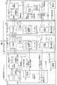
本発明の第1の実施形態に係る画像送受信システム1について、図1を参照して説明する。図1は、画像送受信システム1の構成を示すブロック図である。
(Outline of image transmission / reception system 1)
An image transmitting and receiving
図1に示すように、画像送受信システム1は、アクティブ光ケーブル10(アクティブケーブル)、カメラ30、及びグラバ40を備えている。以下においてアクティブケーブルとは、外部から供給される外部電力によって動作する素子及び回路の少なくとも何れかを備えているケーブルのことを指す。また、外部電力によって動作する素子及び回路のことをアクティブ素子と総称する。アクティブ素子の例としては、パラレル/シリアル(P/S)変換部、シリアル/パラレル(S/P)変換部、電気/光(E/O)変換部、光/電気(O/E)変換部、シリアライザ、デシリアライザなどが挙げられる。
As shown in FIG. 1, the image transmission /
また、アクティブ光ケーブル(AOC;Active Optical Cable)とは、アクティブケーブルが備えている信号線のうち、少なくとも高速信号(例えば、画像信号)を伝送するための信号線が光ファイバによって構成されているケーブルのことを指す。アクティブ光ケーブルに対して、高速信号(例えば、画像信号)を伝送するための信号線が金属配線によって構成されているケーブルのことをアクティブメタルケーブルと呼ぶ。 Also, an active optical cable (AOC) is a cable in which at least a signal line for transmitting a high-speed signal (for example, an image signal) among signal lines included in the active cable is formed by an optical fiber. Point to A cable in which a signal line for transmitting a high-speed signal (for example, an image signal) to the active optical cable is formed by metal wiring is called an active metal cable.
カメラ30は、静止画像又は動画像を撮像する撮像装置であり、かつ、撮像した静止画像又は動画像を表す画像信号を、アクティブ光ケーブルを介して送信する画像送信装置である。
The
グラバ40は、アクティブ光ケーブル10を介してカメラ30が送信した画像信号を受信する画像受信装置であり、かつ、コンピュータに装着されることによって、受信した画像信号を、コンピュータに入力する画像入力インターフェースボードである。アクティブ光ケーブル10を介してカメラ30と接続されたグラバ40が装着されたコンピュータは、画像処理装置として機能する。
The
以下において、アクティブ光ケーブル10を介して、カメラ30からグラバ40への伝送方向を下り方向と定義し、グラバ40からカメラ30への伝送方向を上り方向と定義する。
Hereinafter, the transmission direction from the
まず、画像送受信システム1におけるカメラ30、アクティブ光ケーブル10、及びグラバ40の基本的な構成を説明する。その後に、アクティブ光ケーブル10のカメラ側コネクタ11(送信側コネクタ)及びグラバ側コネクタ12(受信側コネクタ)を監視(モニター)及び制御するための構成について説明する。
First, basic configurations of the
(カメラ30)
図1に示すように、カメラ30は、カメラコントローラ31、センサユニット32、信号処理部34、時分割多重化回路35(MUX)、及び電圧変換部36を備えている。
(Camera 30)
As shown in FIG. 1, the
カメラコントローラ31は、カメラ30が備えている各部を制御するものであり、具体的にはマイクロコントローラ(MCU:Micro Controller Unit)である。カメラコントローラ31は、カメラ側コネクタ11のO/E変換部113から取得したトリガ信号に従って、図示しないシャッターのシャッタータイミングを制御する。なお、カメラコントローラ31は、MCUではなく、例えばFPGA(Field Programmable Gate Array)などで構成されていてもよい。
The
カメラコントローラ31は、機能ブロックとしてデコーダ311及びコネクタ制御部312を備えている。デコーダ311は、カメラ側コネクタ11のO/E変換部113から取得したカメラ制御信号(画像送信装置制御信号)をデコードし、カメラコントローラ31に供給する。カメラコントローラ31は、デコードされたカメラ制御信号に従って、センサユニット32、信号処理部34、及びMUX35を制御する。
The
O/E変換部113から取得したカメラ制御信号には、カメラ側コネクタ11のアクティブ素子(特にE/O変換部112)をグラバ40が制御するためのカメラ側コネクタ制御信号、及び、カメラ側コネクタ11の内部状態をグラバ40が監視(モニター)できるようにするためのカメラ側コネクタ監視信号が含まれている。デコーダ311は、上述のとおりカメラ制御信号をデコードすると共に、カメラ制御信号に重畳されているカメラ側コネクタ制御信号及びカメラ側コネクタ監視信号を分離する。カメラ側コネクタ制御信号及びカメラ側コネクタ監視信号の詳細については、カメラ側コネクタ11の内部情報と合わせて後述する。なお、カメラ側コネクタ制御信号及びカメラ側コネクタ監視信号を区別する必要がない場合には、両者をまとめてカメラ側コネクタ制御信号と総称する。コネクタ制御部312の働きについても、カメラ側コネクタ11の内部情報と合わせて後述する。
In the camera control signal acquired from the O /
センサユニット32は、図示しない撮像センサ、図示しないA/D変換部、図示しない同期信号生成部、図示しないアナログ画像処理部を備えている。撮像センサは、マトリククス状に配置された複数の画素を備えている。撮像センサの各画素は、受光した光の強度を、その光の強度に応じた電圧に変換する。したがって、撮像センサは、図示しない光学系を介して入射してくる光を画像として撮像し、この画像を表すアナログの画像信号に変換し、この画像信号をA/D変換部に提供する。撮像センサは、赤(R)、緑(G)、及び青(B)それぞれの光の強度を検出可能なカラー撮像センサであってもよいし、モノクロ撮像センサであってもよい。以下においては、カラー撮像センサであるものとして説明する。
The
A/D変換部は、撮像センサから取得したアナログの画像信号を、Rが8ビット、Gが8ビット、及びBが8ビットからなる合計24ビットのデジタルの画像信号に変換する。ここで、それぞれ8ビットであるRGBの各画像信号は、それぞれが1つのパラレル信号系列を構成する。したがって、合計24ビットの画像信号は、3つのパラレル信号系列を構成する。A/D変換部は、画像信号の態様をアナログからデジタルに変換するときに、図示しないクロック発生源から供給されるクロック(CLK)を用いる。以下において、「アナログの画像信号」と明記せずに単に「画像信号」と記載した場合は、デジタルの画像信号であることを意味する。A/D変換部は、A/D変換したデジタルの画像信号を信号処理部34に供給する。なお、ここではRGBの各画像信号のビット数が8ビットであるものとして説明するが、RGBの各画像信号のビット数は、8ビットに限定されるものではない。RGBの各画像信号のビット数は、例えば10ビットであってもよいし、12ビットであってもよい。したがって、RGBの各画像信号の合計ビット数は、24ビットより多くてもよい。
The A / D conversion unit converts an analog image signal acquired from the imaging sensor into a digital image signal of 24 bits in total including 8 bits of R, 8 bits of G, and 8 bits of B. Here, each image signal of RGB, which is 8 bits each, constitutes one parallel signal sequence. Therefore, a total of 24 bit image signals constitute three parallel signal sequences. The A / D conversion unit uses a clock (CLK) supplied from a clock generation source (not shown) when converting an aspect of the image signal from analog to digital. In the following, when simply described as "image signal" without specifying "analog image signal", it means that it is a digital image signal. The A / D conversion unit supplies the digital image signal subjected to A / D conversion to the
アナログ画像処理部は、撮像センサが提供するアナログの画像信号に対して、アナログゲイン、アナログオフセット、及びアナログフィルタなどのアナログ画像処理を必要に応じて実行する。アナログ画像処理部は、必要に応じてアナログ画像処理を施したアナログの画像信号をA/D変換部に提供する。すなわち、アナログ画像処理部が実行するこれらのアナログ画像処理は、カメラ30において必須の処理ではない。
The analog image processing unit performs analog image processing such as analog gain, analog offset, and analog filter on an analog image signal provided by the imaging sensor as necessary. The analog image processing unit provides an analog image signal subjected to analog image processing as necessary to an A / D conversion unit. That is, the analog image processing performed by the analog image processing unit is not an essential process in the
同期信号生成部は、A/D変換部で変換されたデジタルの画像信号に同期した同期信号である垂直同期、水平同期、及び有効データを生成する。垂直同期、水平同期、及び有効データの各同期信号のビット数は、それぞれ1ビットである。 The synchronization signal generation unit generates vertical synchronization, horizontal synchronization, and valid data, which are synchronization signals synchronized with the digital image signal converted by the A / D conversion unit. The number of bits of each of the vertical synchronization, horizontal synchronization, and valid data synchronization signals is one bit.
信号処理部34は、図示しないクロック発生源から供給されるCLKと、同期信号生成部から取得した3つの同期信号(垂直同期、水平同期、及び有効データ)とを用いて、A/D変換部から取得した3つのパラレル信号系列からなるデジタルの画像信号に対してデジタルゲイン、デジタルオフセット、及びデジタルフィルタなどのデジタル画像処理を施す。すなわち、信号処理部34が実行するこれらのデジタル画像処理は、カメラ30にとって必須の処理ではない。信号処理部34は、必要に応じてデジタル画像処理された24ビットの画像信号と、上述した3つの同期信号(垂直同期、水平同期、及び有効データ)と、CLKとをMUX35に供給する。
The
MUX35は、信号処理部34から取得した3つのパラレル信号系列からなる画像信号と上記同期信号とを、CLKを用いて4対の差動信号に時分割多重する。MUX35は、例えば市販のFPGAを用いて構成することができる。図2の(a)は、FPGAとしてAltera社製のCycloneVを用いてMUX35を構成した場合のMUX35のブロック図である。図2の(a)に示すブロック図は、8ビットのパラレル信号を時分割多重することによって1対のシリアル信号を生成する1レーン分の時分割多重ブロックを示している。この時分割多重ブロックは、図2の(a)に示すように8B/10Bエンコーディングと呼ばれる方法を用いて、8ビットのパラレル信号をエンコードした後、エンコードされたパラレル信号をシリアライザで1対のシリアル信号に時分割多重する。
The
MUX35は、少なくとも24ビットの画像信号と、3ビットの同期信号を含んでいるため、図2に示す時分割多重ブロックを4レーン備えていればよい。MUX35が上記時分割多重ブロックを4レーン備えている場合、最大32ビットのデータを時分割多重することができるため、画像信号及び同期信号以外のデータを画像信号及び同期信号と併せて時分割多重することができる。
The
また、MUX35は、市販のIC(Integrated Circuit)を用いて構成することもできる。本実施形態では、図3の(a)に示すように、TexasInstruments社製のシリアライザ(Serializer)ICであるDS92LV3241を用いてMUX35を構成している。また、図3の(b)には、後述するDEMUX42として機能するデシリアライザ(Deserializer)ICであるDS92LV3242を示している。
The
図3に示すとおり、MUX35は、取得した最大で32ビットのパラレル信号(TxIN0〜TxIN31)を時分割多重することによって、4対の差動信号(TxOUT0の+及び−、TxOUT1の+及び−、TxOUT2の+及び−、並びに、TxOUT3の+及び−)を生成することができる。DEMUX42については、グラバ40を説明するときに後述する。
As shown in FIG. 3, the
MUX35は、時分割多重することによって生成した4対の差動信号(以下において第1〜第4の画像信号と呼ぶ)を、カメラ側コネクタ11のE/O変換部112に供給する。
The
(アクティブ光ケーブル10)
図1に示すように、アクティブ光ケーブル10は、カメラ側コネクタ11、グラバ側コネクタ12、下り光ファイバ13、上り光ファイバ14、及び電力線15を備えている。
(Active optical cable 10)
As shown in FIG. 1, the active
カメラ側コネクタ11は、アクティブ光ケーブル10の一端に設けられており、カメラ30に接続されている。グラバ側コネクタ12は、アクティブ光ケーブル10の他端に設けられており、グラバ40に接続されている。
The
下り光ファイバ13は、カメラ30から供給された4対の差動信号である上記画像信号をグラバ40に伝送するための信号線であり、4本の光ファイバ131〜134を備えている。
The downstream
上り光ファイバ14は、カメラを制御するためのカメラ制御信号を伝送する光ファイバ141と、カメラにシャッタータイミングを指示するためのトリガ信号を伝送する光ファイバ142とを備えている。なお、アクティブ光ケーブル10に対して、上り4本/下り4本の光ファイバを複合したQSFPアクティブ光ケーブルの技術を適用する場合、アクティブ光ケーブル10は、E/O変換部122が備えている4個の発光部のうち光ファイバ141,142に対応する2個の発光部を用いて、カメラ制御信号及びトリガ信号を伝送すればよい。言い換えれば、4個の発光部のうち2個の発光部を無効化し、無効化した2個の発光部に対応する2本の光ファイバを未使用とすればよい。画像信号、カメラ制御信号、及びトリガ信号については、後述する。ここで、発光部を無効化するとは、発光部(例えば、レーザ素子)に供給する電流を、その発光素子の閾値電流以下にする(例えば、0mAにする)ことを指す。なお、本実施形態では、上り光ファイバ14が2つの信号(カメラ制御信号及びトリガ信号)を伝送する構成を採用しているため、E/O変換部122が備えている4個の発光部のうち2つの発光部を無効化している。しかし、上り光ファイバ14が伝送する信号の数に応じて、無効化する発光部の数は、1個以上3個以下のいずれであってもよい。この構成によれば、発光部を無効化しない場合と比較して、グラバ側コネクタ12における消費電力を抑制することができる。
The upstream
なお、アクティブ光ケーブル10に対して、例えば上り12本/下り12本の光ファイバを複合したCXP(C=hex character for 12; XP=eXtended capability Pluggable)アクティブ光ケーブルの技術を適用する場合には、E/O変換部122が備えている12個(N=12)の発光部のうち10個(N−M個)の発光部を無効化し、無効化した10個の発光部に対応する10本の光ファイバを未使用とすればよい。
When applying the technology of CXP (C = hex character for 12; XP = eXtended capability Pluggable) active optical cable in which, for example, 12 upstream and 12 downstream optical fibers are combined for the active
電力線15は、グラバ40の電源部44から供給される電力を、グラバ側コネクタ12、カメラ側コネクタ11、及びカメラ30のそれぞれに供給するための金属配線である。電力線15には、定電圧源である電源44から所定の電圧(例えば、直流12V)の電力が供給されている。
The power line 15 is a metal wiring for supplying the power supplied from the
カメラ側コネクタ11は、カメラ側コントローラ111、電気/光変換部(E/O変換部)112、光/電気変換部(O/E変換部)113、温度センサ114、及び電圧変換部115を備えている。
The camera-
電圧変換部115は、電力線15によって供給される電力の電圧を所定の電圧(例えば、直流3.3V)に変換したうえで、電圧変換後の電力を、カメラ側コントローラ111、E/O変換部112、O/E変換部113、及び温度センサ114に供給する。アクティブ素子であるカメラ側コントローラ111、E/O変換部112、O/E変換部113、及び温度センサ114のそれぞれは、電圧変換部115から供給される電力によって駆動される。
The
カメラ側コントローラ111は、E/O変換部112と、O/E変換部113とを制御するものであり、具体的にはMCUである。また、カメラ側コントローラ111が備えている内部情報提供部111aは、カメラ側コネクタ11の動作状態に関わる内部状態を示す内部情報を、カメラ30に提供する。なお、この内部情報については後述する。
The camera-
E/O変換部112は、図示しないレーザ駆動部と、図示しない発光部であるレーザ素子とを備えている。E/O変換部112は、カメラ30のMUX35から供給された電気信号である画像信号を光信号である画像信号に変換する。その後、E/O変換部112は、光信号に変換した画像信号を下り光ファイバ13に結合させる。なお、E/O変換部112のレーザ素子としては、例えば垂直共振器面発光レーザ(VCSEL)と呼ばれるタイプのレーザ素子を利用可能である。
The E /
具体的には、E/O変換部112は、MUX35から4対の差動信号である画像信号(第1〜第4の画像信号)を取得する。第1の画像信号を例にすると、E/O変換部112のレーザ駆動部は、カメラ側コントローラ111から取得する制御信号に従って、設定されたバイアス電流及び変調電流に基づいた電流信号をレーザ素子へ供給する。レーザ素子は、レーザ駆動部から取得した電流信号に基づいて発光強度を変調されたレーザ光、すなわち光信号である第1の画像信号を、光ファイバ131に対して出射する。以上の工程により、E/O変換部112は、第1の画像信号の態様を電気信号から光信号へ変換する。
Specifically, the E /
同様に、E/O変換部112は、第2の画像信号の態様を電気信号から光信号へ変換した後に光ファイバ132に結合させ、第3の画像信号の態様を電気信号から光信号へ変換した後に光ファイバ133に結合させ、第4の画像信号の態様を電気信号から光信号へ変換した後に光ファイバ134に結合させる。
Similarly, the E /
また、E/O変換部112は、レーザ素子を駆動するときのバイアス電流をカメラ側コントローラ111の内部情報提供部111aに提供する。このバイアス電流は、カメラ側コネクタ11の内部状態を示す前記内部情報の1つである。カメラ側コネクタ11の内部情報をグラバ40に送信する方法については後述する。
In addition, the E /
一方、O/E変換部113は、図示しない受光部と電流電圧変換部とを備えている。O/E変換部113は、上り光ファイバ14によって伝送されてきたカメラ制御信号の態様を光信号から電気信号へ変換し、トリガ信号の態様を光信号から電気信号へ変換する。その後、O/E変換部113は、電気信号に変換したカメラ制御信号及びトリガ信号を、カメラ30のカメラコントローラ31に供給する。なお、O/E変換部113の受光部としては、例えばGaAsのPIN型フォトダイオード(PIN−PD)を利用可能である。
On the other hand, the O /
具体的には、O/E変換部113の受光部は、光ファイバ141から光信号であるカメラ制御信号を受光する。受光部であるフォトダイオードは、受光したカメラ制御信号を表す光信号の光強度を、対応するフォトダイオード電流に変換する。フォトダイオードは、変換したフォトダイオード電流を電流電圧変換部へ供給する。電流電圧変換部は、受光部であるフォトダイオードから取得したフォトダイオード電流を、対応する電圧に変換する。電流電圧変換部は、フォトダイオード電流に対応する電圧、すなわち電気信号をカメラコントローラ31に対して供給する。以上の工程により、O/E変換部113は、カメラ制御信号の態様を光信号から電気信号に変換する。
Specifically, the light receiving unit of the O /
同様に、O/E変換部113は、トリガ信号の態様を光信号から電気信号へ変換した後にカメラコントローラ31に供給する。
Similarly, the O /
温度センサ114は、E/O変換部112のレーザ素子の近傍領域に配置されており、レーザ素子の近傍領域の温度を検出する。温度センサ114は、検出したレーザ素子の近傍領域の温度を内部情報提供部111aに提供する。レーザ素子の近傍領域の温度は、カメラ側コネクタ11の内部状態を示す前記内部情報の1つである。カメラ側コネクタ11の内部情報をグラバ40に送信する方法については後述する。
The
次に、グラバ側コネクタ12について説明する。グラバ側コネクタ12は、グラバ側コントローラ121、E/O変換部122、O/E変換部123、温度センサ124、及び電圧変換部125を備えている。
Next, the
電圧変換部125は、電力線15によって供給される電力の電圧を所定の電圧(例えば、直流3.3V)に変換したうえで、電圧変換後の電力を、グラバ側コントローラ121、E/O変換部122、O/E変換部123、及び温度センサ124に供給する。アクティブ素子であるグラバ側コントローラ121、E/O変換部122、O/E変換部123、及び温度センサ124のそれぞれは、電圧変換部125から供給される電力によって駆動される。
The
グラバ側コントローラ121は、グラバ側コネクタ12が備えている各部を制御するものであり、具体的にはMCUである。
The grabber-
E/O変換部122は、図示しないレーザ駆動部と、レーザ素子とを備えており、カメラ側コネクタ11のE/O変換部112と同様に構成されている。E/O変換部112がMUX35から取得した画像信号の態様を電気信号から光信号に変換するのに対し、E/O変換部122は、グラバ40のグラバコントローラ41から取得したカメラ制御信号及びトリガ信号の態様を電気信号から光信号に変換する。
The E /
グラバコントローラ41から取得したカメラ制御信号を例にすると、E/O変換部122のレーザ駆動部は、グラバ側コントローラ121から取得する制御信号に従って、設定されたバイアス電流及び変調電流に基づいた電流信号をレーザ素子へ供給する。レーザ素子は、レーザ駆動部から取得した電流信号に基づいて発光強度を変調されたレーザ光、すなわち光信号であるカメラ制御信号を、光ファイバ141に対して結合させる。以上の工程により、E/O変換部122は、カメラ制御信号の態様を電気信号から光信号へ変換する。
Taking the camera control signal acquired from the
同様に、E/O変換部122は、トリガ信号の態様を電気信号から光信号に変換した後に光ファイバ142に結合させる。
Similarly, the E /
また、E/O変換部122は、レーザ素子を駆動するときのバイアス電流をグラバ側コントローラ121に提供する。このバイアス電流は、グラバ側コネクタ12の内部状態を示す内部情報の1つである。グラバ側コネクタ12の内部情報をグラバ40に送信する方法については後述する。
Further, the E /
一方、O/E変換部123は、図示しない受光部と電流電圧変換部とを備えており、カメラ側コネクタ11のO/E変換部113と同様に構成されている。O/E変換部113が上り光ファイバ14によって伝送されてきたカメラ制御信号及びトリガ信号の態様を光信号から電気信号に変換するのに対し、E/O変換部123は、下り光ファイバ14によって伝送されてきた第1〜第4の画像信号の態様を光信号から4対の差動信号からなる電気信号に変換する。
On the other hand, the O /
具体的には、O/E変換部123の受光部は、光ファイバ131から光信号である第1の画像信号を受光する。受光部であるフォトダイオードは、受光した第1の画像信号を表す光信号の強度を対応するフォトダイオード電流に変換し、このフォトダイオード電流を電流電圧変換部へ供給する。電流電圧変換部は、フォトダイオードから取得したフォトダイオード電流を、対応する電圧に変換する。電流電圧変換部は、このフォトダイオード電流に対応する電圧を電気信号である第1の画像信号として、グラバ40のDEMUX42に対して供給する。より詳しくは、電流電圧変換部は、上記フォトダイオード電流に対応する電圧に対応する1対の差動信号に変換し、この1対の差動信号を第1の画像信号としてDEMUX42に対して供給する。以上の工程により、OE変換部123は、第1の画像信号の態様を光信号から電気信号に変換する。
Specifically, the light receiving unit of the O /
同様に、O/E変換部123は、第2の画像信号の態様を光信号から1対の差動信号である電気信号に変換し、第3の画像信号の態様を光信号から1対の差動信号である電気信号に変換し、第4の画像信号の態様を光信号から1対の差動信号である電気信号に変換する。O/E変換部123は、第1の画像信号と共に第2〜第4の画像信号をDEMUX42に供給する。
Similarly, the O /
温度センサ124は、E/O変換部122のレーザ素子の近傍領域に配置されており、レーザ素子の近傍領域の温度を検出する。温度センサ124は、検出したレーザ素子近傍領域の温度を内部情報提供部121aに提供する。レーザ素子の近傍領域の温度は、グラバ側コネクタ12の内部状態を示す内部情報の1つである。グラバ側コネクタ12の内部情報をグラバ40に送信する方法については後述する。
The
(グラバ40)
図1に示すように、グラバ40は、グラバコントローラ41、多重分離回路42(DEMUX)、信号処理部43、及び電源部44を備えている。
(Grabber 40)
As shown in FIG. 1, the
グラバコントローラ41は、グラバ40が備えている各部を制御するものであり、具体的にはマイクロコントローラである。グラバコントローラ41は、画像処理装置であるコンピュータからの制御信号に従って、DEMUX42、信号処理部43、及び電源部44を制御する。
The
グラバコントローラ41は、機能ブロックとしてエンコーダ411及びコネクタ制御部412を備えている。エンコーダ411は、カメラ30に送信するカメラ制御信号をデータ送信用フォーマットにエンコードし、グラバ側コネクタ12のE/O変換部122に供給する。ここで、データ送信用フォーマットとは、画像処理装置であるコンピュータがカメラ制御信号を処理する時に用いるフォーマットと比較して、伝送に適した態様のフォーマットのことを意味する。データ送信用フォーマットの具体例としては、RS−232C(EIA−232規格)によって規定されるフォーマット、及び、CMI(Coded Mark Inversion)符号方式を用いたフォーマットが挙げられる。
The
また、グラバコントローラ41は、トリガ信号をE/O変換部122に供給する。トリガ信号は、カメラ30が撮像するシャッタータイミングを制御するトリガとなる信号を含んでいる。グラバコントローラ41が供給するトリガ信号は、非時分割多重のリアルタイムの信号である。
In addition, the
DEMUX42は、グラバ側コネクタ12のO/E変換部123から4つの画像信号(第1〜第4の画像信号)を取得する。DEMUX42は、4対の差動信号である第1〜第4の画像信号を時分割分離することによって、3つのパラレル信号系列からなる画像信号と前記同期信号とを復元する。
The
DEMUX42は、例えば市販のFPGAを用いて構成することができる。図2の(b)は、FPGAとしてAltera社製のCycloneVを用いてDEMUX42を構成した場合のブロック図である。図2の(b)に示すブロック図は、1対のシリアル信号を時分割分離することによって8ビットのパラレル信号を生成する1レーン分の時分割分離ブロックを示している。この時分割分離ブロックは、図2の(a)に示した8B/10Bエンコーディングの逆の方法を用いて、1対のシリアル信号をデコードした後、デコードされたシリアル信号をデシリアライザで8ビットのパラレル信号に時分割分離する。なお、図2の(a)及び(b)において実行されるエンコーディング/デコーディングの方法は、8B/10Bエンコーディング/デコーディングに限定されるものではなく、例えば、64B/66Bエンコーディング/デコーディングであってもよい。
The
また、DEMUX42は、市販のICを用いて構成することもできる。図3の(b)に、本実施形態でDEMUX42として用いているTexasInstruments社製のデシリアライザICであるDS92LV3242を示している。図3の(b)に示したとおり、DEMUX42は、取得した4対の差動信号(RxIN0の+及び−、RxIN1の+及び−、RxIN2の+及び−、並びに、RxIN3の+及び−)を時分割分離することによって、32ビットのパラレル信号(RxOUT0〜RxOUT31)を生成することができる。
The
DEMUX42は、時分割分離することによって生成した32ビットのパラレル信号に含まれている3つの画像信号と同期信号とを信号処理部43に供給する。
The
信号処理部43は、DEMUX42から取得したパラレル信号である3つの画像信号を、同期信号を用いてグラバ40が処理可能なフォーマットの画像信号に変換する。信号処理部43は、グラバ40が処理可能なフォーマットに変換した3つの画像信号を、グラバコントローラ41に供給する。グラバコントローラ41は、上記3つの画像信号を画像処理装置として機能するコンピュータに供給する。
The
電源部44は、グラバ40が備えているグラバコントローラ41、DEMUX42、及び信号処理部43に電力を供給するとともに、電力線15にも電力を供給する。電源部44は、グラバ40、アクティブ光ケーブル10、及びカメラ30に対して所定の電力を供給可能なように構成されていればよく、既存の技術(例えば、カメラリンクケーブルにおけるPoCL(Power over Camera Link)の技術)を用いて実現することができる。
The
(カメラ側コネクタ11及びグラバ側コネクタ12の監視)
上述したように、アクティブ光ケーブル10のカメラ側コネクタ11及びグラバ側コネクタ12は、各々に対応するE/O変換部112及び122と、O/E変換部113及び123とを備えている。上述したように、E/O変換部112及び122は、電気信号を光信号に変換するために、光信号の媒体であるレーザ光を出射するレーザ素子を備えている。
(Monitoring of the
As described above, the camera-
一般的に、レーザ素子が発するレーザ光のパワーは、レーザ素子のバイアス電流と、レーザ素子の温度とに大きく依存する。したがって、アクティブ光ケーブル10が接続されているグラバ40は、(i)カメラ側コネクタ11が備えているE/O変換部112のレーザ素子(以下、第1のレーザ素子)のバイアス電流を表すバイアス電流情報(以下、第1のバイアス電流情報)と、カメラ側コネクタ11の内部(第1のレーザ素子の近傍領域)の温度を表す温度情報(以下、第1の温度情報)と、を取得可能なように構成されている。さらに、グラバ40は、(ii)グラバ側コネクタ12が備えているE/O変換部122のレーザ素子(以下、第2のレーザ素子)のバイアス電流を表すバイアス電流情報(以下、第2のバイアス電流情報)と、グラバ側コネクタの内部(第2のレーザ素子の近傍領域)の温度を表す温度情報(以下、第2の温度情報)と、を取得可能なようにも構成されている。なお、以下において、カメラ側コネクタ11の内部状態を示す第1のバイアス電流情報と第1の温度情報とをまとめて第1の内部情報と総称し、グラバ側コネクタ12の内部状態を示す第2のバイアス電流情報と第2の温度情報とをまとめて第2の内部情報と総称する。
In general, the power of laser light emitted from a laser element largely depends on the bias current of the laser element and the temperature of the laser element. Therefore, the
このように、グラバ40がカメラ側コネクタ11から第1の内部情報を取得することによって、カメラ側コネクタ11の内部状態を把握することを、「グラバ40がカメラ側コネクタ11の内部状態を監視する」と呼ぶ。同様に、グラバ40がグラバ側コネクタ12から第2の内部情報を取得することによって、グラバ側コネクタ12の内部状態を把握することを、「グラバ40がグラバ側コネクタ12の内部状態を監視する」と呼ぶ。この内部状態を「監視する」行為は、内部状態を「モニターする」行為とも言い換えられる。
As described above, the
(カメラ側コネクタ11に対する監視方法)
ここでは、グラバ40がカメラ側コネクタ11を監視する場合の監視方法を、図4を参照して説明する。その後に、グラバ40がカメラ側コネクタ11を制御する場合の制御方法を、図5を参照して説明する。また、カメラ制御信号、カメラ側コネクタ制御信号、及びグラバ側コネクタ制御信号について、図6を参照して説明する。
図4は、グラバ40がカメラ側コネクタ11を監視する場合のフローチャートである。図5は、グラバ40がカメラ側コネクタ11を制御する場合のフローチャートである。図6は、カメラ制御信号、カメラ側コネクタ制御信号、及びグラバ側コネクタ制御信号のデータ構造の一例を表す表である。
(Monitoring method for camera side connector 11)
Here, a monitoring method in the case where the
FIG. 4 is a flowchart when the
ここでは、グラバ40がカメラ側コネクタ11に対して、カメラ側コネクタ11を監視する旨のカメラ側コネクタ監視信号を送信し、カメラ側コネクタ11は、受信したカメラ側コネクタ監視信号に基づいて第1の内部情報をグラバ40へ送信する場合について説明する。なお、グラバ40がカメラ側コネクタ監視信号を送信し、カメラ側コネクタ11の内部情報を取得することによって実現されるカメラ側コネクタ11の監視は、後述するカメラ側コネクタ11の制御の一態様であるとも考えられる。そこで、以下では、カメラ側コネクタ11を監視するためのカメラ側コネクタ監視信号と、カメラ側コネクタ11を制御するためのカメラ側コネクタ制御信号とを、区別せずにカメラ側コネクタ制御信号とも総称する。
Here, the
まず、図6を参照してカメラ制御信号及びカメラ側コネクタ制御信号のデータ構造の一例について説明する。図6に示すように、カメラ制御信号及びカメラ側コネクタ制御信号は、例えば図6に示すデータ構造によって規定されている14バイトのシリアルコマンドである。 First, an example of the data structure of the camera control signal and the camera side connector control signal will be described with reference to FIG. As shown in FIG. 6, the camera control signal and the camera side connector control signal are, for example, 14-byte serial commands defined by the data structure shown in FIG.
1〜6バイト目のコマンドは、カメラ制御信号が制御対象とするカメラを特定するために用いられる。カメラを他のカメラから識別するために、画像送受信システム1において使用されるカメラには、各カメラに固有の識別番号が割り当てられている。また、画像送受信システム1においては、同システムに含まれているカメラのみならず、同システムに含まれているアクティブ光ケーブルのカメラ側コネクタ及びグラバ側コネクタにも識別番号が割り当てられている。
The first to sixth byte commands are used to specify a camera to be controlled by the camera control signal. A unique identification number is assigned to each camera used in the image transmission /
以下において、カメラ30の識別番号は「000001」であり、カメラ側コネクタ11の識別番号は「000002」であり、グラバ側コネクタ12の識別番号は「000003」であるものとする。カメラ30を制御対象とするカメラ制御信号を生成する場合、画像処理装置であるコンピュータは、1〜6バイト目のコマンドが「000001」であるカメラ制御信号を生成する。また、カメラ側コネクタ11を制御対象とするカメラ制御信号を生成する場合には、1〜6バイト目のコマンドを「000002」とすればよく、グラバ側コネクタ12を制御対象とするカメラ制御信号を生成する場合には、1〜6バイト目のコマンドを「000003」とすればよい。
In the following, it is assumed that the identification number of the
7バイト目のコマンドは、カメラ制御信号の処理コードを指定するコマンドであり、リードモード(R)、ライトモード(W)、及びACKモード(A)の何れかに対応するコマンドが指定される。 The command of the 7th byte is a command for specifying the processing code of the camera control signal, and a command corresponding to any one of the read mode (R), the write mode (W) and the ACK mode (A) is specified.
8〜10バイト目のコマンドは、カメラ30、カメラ側コネクタ11及びグラバ側コネクタ12の何れかが備えているEEPROM(登録商標)/RAMのアドレスを指定する。
The command of the 8th to 10th bytes designates the address of the EEPROM (registered trademark) / RAM provided in any of the
11〜13バイト目のコマンドは、ライトモードの場合に8〜10バイト目のコマンドによって指定されるEEPROM(登録商標)/RAMのアドレスに書き込まれる実行データを指定する。なお、リードモード及びACKモードの場合には、11〜13バイト目のコマンドは特に指定されない。 The 11th to 13th byte commands designate execution data to be written to the EEPROM (registered trademark) / RAM address specified by the 8th to 10th byte commands in the write mode. In the read mode and the ACK mode, the commands in the 11th to 13th bytes are not specified.
14バイト目のコマンドには、カメラ制御信号の最後のコマンドであることを意味する「0Dh」が指定される。 In the 14th byte command, “0Dh” is specified, which means that it is the last command of the camera control signal.
次に、図4を参照して、グラバ40がカメラ側コネクタ11を監視する場合の監視方法を説明する。「カメラ側コネクタ11に対する制御方法」の項に後述するように、グラバ40がカメラ側コネクタ11を制御する場合に、コネクタ制御部412は、制御対象をカメラ側コネクタ11とするカメラ側コネクタ制御信号を生成し、エンコーダ411に提供する(ステップS111参照)。一方、グラバ40がカメラ側コネクタ11を監視する場合に、コネクタ制御部412は、制御対象をカメラ側コネクタ11とするカメラ側コネクタ制御信号を生成しない。すなわち、コネクタ制御部412は、カメラ側コネクタ制御信号をエンコーダ411に提供しない。したがって、この場合、エンコーダ411は、上記コンピュータからカメラ制御信号のみを取得する。エンコーダ411は、上記コンピュータから取得したカメラ制御信号をデータ送信用フォーマットに変換し、グラバ側コネクタ12のE/O変換部122に提供する。
Next, referring to FIG. 4, a monitoring method in the case where the
なお、ここでは、カメラ制御信号が14バイトのシリアルコマンドであるものとして説明した。しかし、カメラ制御信号としては、Genicam(EMVA、http://www.emva.org/cms/index.php?idcat=27)において定められているような汎用規格のコマンドを利用することもできる。 Here, it has been described that the camera control signal is a 14-byte serial command. However, as a camera control signal, a general-purpose command as defined in Genicam (EMVA, http://www.emva.org/cms/index.php?idcat=27) can also be used.
次に、グラバ40がカメラ側コネクタ11を監視する場合の監視方法について説明する。
Next, a monitoring method in the case where the
グラバコントローラ41のコネクタ制御部412がカメラ側コネクタ11を制御する場合、コネクタ制御部412は、制御対象をカメラ側コネクタ11とするカメラ側コネクタ制御信号を生成し、エンコーダ411に提供する(ステップS111)。ここで、カメラ側コネクタ制御信号のデータ構造は、図6に示したカメラ制御信号のデータ構造と同じである。したがって、制御対象としてカメラ側コネクタ11を指定する場合、コネクタ制御部412は、1〜6バイト目のコマンドを「000002」とすればよい。
When the
7〜13バイト目のコマンドには、カメラ側コネクタ11に対して第1の内部情報を送信させる、言い換えればカメラ側コネクタ11から第1の内部情報を読み取る制御に対応したコマンドを指定する。具体的には、7バイト目のコマンドとしてリードモードに対応する「R」を指定し、8〜10バイト目のコマンドとしてカメラ側コネクタ11のカメラ側コントローラ111にあるEEPROM/RAMの所定のアドレスを指定する。監視を行うためのカメラ側コネクタ制御信号においては、11〜13バイト目に指定すべき内容はない。
In the 7th to 13th byte commands, a command corresponding to control to cause the
エンコーダ411は、画像処理装置であるコンピュータから、カメラ30を制御するためのカメラ制御信号(画像送信装置制御信号)を取得する(ステップS112)。上述したように、カメラ制御信号において、1〜6バイト目のコマンドは、「000001」である。
The
エンコーダ411は、カメラ側コネクタ11を制御対象とするカメラ側コネクタ制御信号を、カメラ制御信号と同様にデータ送信用フォーマットに変換し、グラバ側コネクタ12のE/O変換部122に提供する(ステップS113)。したがって、エンコーダ411は、カメラ制御信号と、カメラ側コネクタ制御信号とを同一の伝送路を介してE/O変換部122に提供する。カメラ制御信号を取得するタイミングと、カメラ側コネクタ制御信号を取得するタイミングとが重なった場合には、どちらか一方の制御信号(例えばカメラ制御信号)を先にE/O変換部122に提供し、その後に他方(例えばカメラ側コネクタ制御信号)をE/O変換部122に提供するように構成されていてもよい。この場合、エンコーダ411は、カメラ制御信号の無信号期間にカメラ側コネクタ制御信号を挿入する挿入部として機能する。また、1つのコマンドを用いてカメラ制御信号及びカメラ側コネクタ制御信号の2つの制御信号を送信可能なコマンド送信フォーマットが準備されている場合には、エンコーダ411は、カメラ制御信号及びカメラ側コネクタ制御信号をまとめてE/O変換部122に提供するように構成されていてもよい。この場合、エンコーダ411は、カメラ制御信号にカメラ側コネクタ制御信号を重畳する重畳部として機能する。以下においては、エンコーダ411は、カメラ制御信号にカメラ側コネクタ制御信号を重畳する重畳部として機能するものとする。
The
E/O変換部122は、エンコーダ411から取得したカメラ制御信号及びカメラ側コネクタ制御信号の態様を、電気信号から光信号に変換する。その後、E/O変換部122は、光信号に変換したカメラ制御信号及びカメラ側コネクタ制御信号を、上り光ファイバ14の光ファイバ141に結合させる。光ファイバ141は、カメラ制御信号及びカメラ側コネクタ制御信号を、グラバ側コネクタ12のE/O変換部122から、カメラ側コネクタ11のO/E変換部113へ伝送する。
The E /
O/E変換部113は、光ファイバ141が伝送してきたカメラ制御信号及びカメラ側コネクタ制御信号の態様を、光信号から電気信号に変換する。その後、O/E変換部113は、電気信号に変換したカメラ制御信号及びカメラ側コネクタ制御信号を、カメラコントローラ31のデコーダ311に提供する。
The O /
デコーダ311は、E/O変換部122、光ファイバ141、及びO/E変換部113を介して伝送されたカメラ側コネクタ制御信号が重畳されたカメラ制御信号を受信する(ステップS114)。
The
デコーダ311は、取得したカメラ制御信号及びカメラ側コネクタ制御信号のフォーマットを、データ送信用フォーマットから、カメラコントローラ31が処理可能なフォーマット(画像処理装置であるコンピュータが処理可能なフォーマットでもある)に変換する。言い換えれば、デコーダ311は、エンコーダ411が変換したカメラ制御信号及びカメラ側コネクタ制御信号のフォーマットを元のフォーマットに戻す。
The
更にデコーダ311は、変換した制御信号の1〜6バイト目のコマンドを参照し、そのカメラ制御信号又はカメラ側コネクタ制御信号がカメラ側コネクタ11宛であるのか、カメラ30宛であるのか、又は、何れにも該当しないのかを判定する(ステップS115)。言い換えれば、デコーダ311は、制御信号が含む識別番号を確認し、各機器(カメラ40、カメラ側コネクタ11、及びグラバ側コネクタ12)のコントローラへと振り分けることでカメラ制御信号、カメラ側コネクタ制御信号、及びグラバ側コネクタ制御信号を分離する。
Furthermore, the
1〜6バイト目のコマンドがカメラ側コネクタ11の識別番号である「000002」である場合、デコーダ311は、変換した制御信号がカメラコネクタ11を制御対象とするカメラ側コネクタ制御信号であると判定し、当該制御信号をコネクタ制御部312へ提供する(ステップS116)。
When the first to sixth byte commands are “000002” which is the identification number of the
コネクタ制御部312は、取得したカメラ側コネクタ制御信号を、カメラ側コネクタ11のカメラ側コントローラ111に提供する(ステップS117)。したがって、デコーダ311は、カメラ制御信号からカメラ側コネクタ11を制御対象とするカメラ側コネクタ制御信号を分離すると共に、分離したカメラ側コネクタ制御信号をカメラ側コネクタ11に提供する分離部であると言える。
The connector control unit 312 provides the acquired camera connector control signal to the
コネクタ制御部312からカメラ側コネクタ11を制御対象とするカメラ側コネクタ制御信号を取得した場合、カメラ側コントローラ111は、取得したカメラ側コネクタ制御信号の7バイト目に指定されているリードモードを表す「R」と、8〜10バイト目に指定されているEEPROM/RAMのアドレスとに応じて、カメラ側コントローラ111の内部状態を示す内部情報を取得するように内部情報提供部111aを制御する。具体的には、内部情報提供部111aは、E/O変換部112から第1のバイアス電流情報を取得するとともに、温度センサ114から第1の温度情報を取得する(ステップS118)。
When the camera-side connector control signal for controlling the camera-
図1に示すように、カメラ側コネクタ11のカメラ側コントローラ111と、カメラ30が備えているカメラコントローラ31のコネクタ制御部312との間には、双方向通信が可能な信号線が設けられている。内部情報提供部111aは、取得した第1のバイアス電流情報及び第1の温度情報、すなわち第1の内部情報を、当該信号線を介してコネクタ制御部312に提供する(提供ステップ:ステップS119)。コネクタ制御部312は、第1の内部情報を内部情報提供部111aから取得する取得部である。
As shown in FIG. 1, a signal line capable of bi-directional communication is provided between the
コネクタ制御部312は、内部情報提供部111aから提供された第1の内部情報を、MUX35に提供する。
The connector control unit 312 provides the
MUX35は、信号処理部34から取得した3つのパラレル信号系列からなる画像信号と、上述した同期信号と、第1の内部情報とを、第1〜第4の画像信号(4対の差動信号)に時分割多重する。言い換えれば、重畳部であるMUX35は、アクティブ光ケーブル10を介してグラバ40に送信する画像信号に、カメラ側コネクタ11から取得した第1の内部情報を重畳する(重畳ステップ:ステップS120)。
The
第1の内部情報を重畳された第1〜第4の画像信号は、カメラ側コネクタ11のE/O変換部112においてその態様を電気信号から光信号に変換され、下り光ファイバ13によってグラバ側コネクタ12へ伝送される。グラバ側コネクタ12のO/E変換部123は、受信した第1〜第4の画像信号の態様を光信号から電気信号に変換し、変換した画像信号をDEMUX42に提供する。
The first to fourth image signals on which the first internal information is superimposed are converted from electrical signals to optical signals in the E /
DEMUX42は、取得した第1〜第4の画像信号を時分割分離することによって、3つのパラレル信号系列からなる画像信号と、前記同期信号と、第1の内部情報とを復元する。言い換えれば、分離部であるDEMUX42は、アクティブ光ケーブル10を介してカメラ30から受信した画像信号から、第1の内部情報を分離する。DEMUX42は、3つの画像信号からなる画像信号と前記同期信号とを信号処理部43へ提供する。また、DEMUX42は、第1の内部情報をグラバコントローラ41のコネクタ制御部412に提供する。
The
以上の工程によって、カメラ側コントローラ111とグラバ側コントローラ121とを接続する双方向通信可能な信号線を備えていないにも関わらず、グラバ40のグラバコントローラ41は、カメラ側コネクタ11の内部状態を監視することができる。
Even though the signal line capable of bi-directional communication is not provided to connect the
なお、ここでは、カメラ側コントローラ111の内部情報提供部111aは、グラバ40からのカメラ側コネクタ制御信号に基づいて第1の内部情報をE/O変換部112及び温度センサ14から取得し、コネクタ制御部312へ提供するものとして説明したが、内部情報提供部111aは、所定のタイミングにおいて第1の内部情報を取得及び提供するように構成されていてもよい。所定のタイミングは、定期的であってもよいし、非定期的であってもよい。この所定のタイミングが定期的である場合、第1のバイアス電流情報及び第1の温度情報を取得する間隔である第1の取得間隔は、特に限定されるものではない。例えば、上記第1の取得間隔は、10秒に設定されていてもよい。なお、第1のバイアス電流情報を取得するタイミングと第1の温度情報を取得するタイミングとは、同じでもよいし異なっていてもよい。
Here, the internal
なお、ステップS115において、カメラ制御信号又はカメラ側コネクタ制御信号の1〜6バイト目のコマンドがカメラ30の識別番号である「000001」である場合、カメラコントローラ31は、受信した制御信号がカメラ30を制御対象とするカメラ制御信号であると判定し、7〜13バイト目に指定されているコマンドに応じてカメラ30の各部を制御する(ステップS131)。
If the command of the first to sixth bytes of the camera control signal or the camera side connector control signal is “000001” which is the identification number of the
また、ステップS115において、カメラ制御信号又はカメラ側コネクタ制御信号の1〜6バイト目の1〜6バイト目のコマンドがカメラ30の識別番号である「000001」、及び、カメラ側コネクタ11の識別番号である「000002」の何れにも該当しない場合、カメラコントローラ31は、受信したカメラ制御信号又はカメラ側コネクタ制御信号が表す制御を実行しなかった旨を意味する応答信号であるNACK(Negative-Acknowledge)信号を、グラバ40に送信する(ステップS141)。本実施形態において、NACK信号は、図6に示す制御信号の4つの処理コード(リードモード、ライトモード、ACKモード、及びNACKモード)のうちNACKモードを使用する。すなわち、カメラコントローラ31は、NACK信号の7バイト目のコマンドとしてNACKモードを表す「N」を指定する。また、カメラコントローラ31は、NACK信号の1〜6バイト目のコマンドとして自身の識別番号である「000001」を指定する。これらにより、このNACK信号がカメラコントローラ31によって生成されたNACK信号であることを明示することができる。
In step S115, the first to sixth bytes commands of the camera control signal or the camera side connector control signal are the identification numbers of the
(グラバ側コネクタ12に対する監視方法)
次に、グラバ40がグラバ側コネクタ12を監視する場合の監視方法を説明する。グラバ側コントローラ121の内部情報提供部121aは、E/O変換部122から第2のバイアス電流情報を定期的に取得すると共に、温度センサ124から第2の温度情報を定期的に取得する。第2のバイアス電流情報及び第2の温度情報を取得する間隔である第2の取得間隔は、特に限定されるものではない。ここでは、上記第2の取得間隔が10秒に設定されているものとする。なお、第2のバイアス電流情報を取得するタイミングと第2の温度情報を取得するタイミングとは、同じでもよいし異なっていてもよい。
(Monitoring method for grabber side connector 12)
Next, a monitoring method in the case where the
図1に示すように、グラバ側コネクタ12のグラバ側コントローラ121と、グラバ40が備えているグラバコントローラ41のコネクタ制御部412との間には、双方向通信が可能な信号線が設けられている。内部情報提供部121aは、取得した第2のバイアス電流情報及び第2の温度情報、すなわち第2の内部情報を、当該信号線を介してコネクタ制御部412に提供する。
As shown in FIG. 1, a signal line capable of bi-directional communication is provided between the grabber-
以上の工程によって、グラバ40のグラバコントローラ41は、グラバ側コネクタ12の内部状態を監視することができる。
Through the above steps, the
なお、ここでは内部情報の具体例として、第2のバイアス電流情報及び第2の温度情報を挙げてグラバ側コネクタ12の監視について説明した。また、上述したカメラ側コネクタ11に対する監視方法においては、内部情報の具体例として第1のバイアス電流情報及び第1の温度情報を挙げてカメラ側コネクタ11の監視について説明した。しかし、グラバ40がカメラ側コネクタ11及びグラバ側コネクタ12から取得する内部情報はこれらに限定されるものではない。すなわち、グラバ40が監視するアクティブ素子は、E/O変換部112及び122に限定されるものではなく、O/E変換部113及び123であってもよい。例えば、グラバ40は、O/E変換部113の状態を示す内部情報として、O/E変換部113が備えている受光部がカメラコントローラ31に出力する電流値、言い換えれば受光パワーを表す第1の受光パワー情報を取得してもよい。また、グラバ40は、O/E変換部123の状態を示す内部情報として、O/E変換部123が備えている受光部がDEMUX42に出力する電流値、言い換えれば受光パワーを表す第2の受光パワー情報を取得してもよい。O/E変換部113及び123が備えている各受光部が出力する電流値は、各受光部が受光する光信号のパワーに対応する。
Here, as a specific example of the internal information, the monitoring of the
(カメラ側コネクタ11及びグラバ側コネクタ12の制御)
ここまでは、カメラ側コネクタ11の第1の内部情報を、カメラ側コネクタ11からカメラ30を介してグラバ40へ送信することによって、グラバ40がカメラ側コネクタ11を監視する方法について説明した。また、グラバ側コネクタ12の第2の内部情報を、グラバ側コネクタ12からグラバ40へ送信することによって、グラバ40がグラバ側コネクタ12を監視する方法について説明した。以下では、まず、図5を参照してグラバ40がカメラ側コネクタ11を制御する方法について説明し、その後に、グラバ40がグラバ側コネクタ12を制御する方法について説明する。
(Control of the
So far, the method in which the
(カメラ側コネクタ11に対する制御方法)
ここで「グラバ40がカメラ側コネクタ11を制御する」とは、(1)カメラ側コネクタ11が備えているアクティブ素子の各種パラメータをグラバ40からの指示に基づいて変更すること、及び、(2)カメラ側コネクタ11の内部状態を示す第1の内部情報を、カメラ側コネクタ11からグラバ40へ送信させること、を指す。制御の対象となるカメラ側コネクタ11のアクティブ素子がE/O変換部112である場合、グラバ40が変更可能なパラメータとは、例えば、E/O変換部112が備えている第1のレーザ素子のバイアス電流及び変調電流である。また、グラバ40は、TxDIS信号をカメラ側コネクタ11に送信することによって、E/O変換部112が備えている第1のレーザ素子の状態を有効化又は無効化することができる。したがって、第1のレーザ素子の状態(有効又は無効)もアクティブ素子の各種パラメータの1つであると言える。制御の対象となるカメラ側コネクタ11のアクティブ素子がO/E変換部113である場合、グラバ40は、RxDIS信号をカメラ側コネクタ11に送信することによって、O/E変換部113が備えている受光部(フォトダイオード)の状態を有効化又は無効化することができる。したがって、受光部の状態(有効又は無効)もアクティブ素子の各種パラメータの1つであると言える。
(Control method for the camera side connector 11)
Here, “the
グラバコントローラ41のコネクタ制御部412がカメラ側コネクタ11を制御する場合、コネクタ制御部412は、制御対象をカメラ側コネクタ11とするカメラ側コネクタ制御信号を生成し、エンコーダ411に提供する(ステップS211)。ステップS211は、図4に示したステップS111に対応するステップであるが、生成するカメラ側コネクタ制御信号が含む7〜13バイト目のコマンドが異なる。
When the
コネクタ制御部412は、7〜13バイト目のコマンドとして、カメラ側コネクタ11に対して行いたい制御に対応したコマンドを指定する。ここで、コネクタ制御部412がカメラ側コネクタ11に対して送信するカメラ側コネクタ制御信号の表す内容が「E/O変換部112が備えているレーザ素子のバイアス電流を10mAにする」だとすれば、7バイト目のコマンドとしてライトモードに対応する「W」を指定し、8〜10バイト目のコマンドを用いてカメラ側コネクタ11のカメラ側コントローラ111にあるEEPROM/RAMの所定のアドレスを指定し、11〜13バイト目のコマンドとしてバイアス電流を10mAに設定する旨を表すコマンドを指定すればよい。
The
ステップS212〜S217は、図4に記載したステップS112〜S117と同一のステップである。したがって、ここでは、その説明を省略する。 Steps S212 to S217 are the same as steps S112 to S117 described in FIG. Therefore, the description is omitted here.
コネクタ制御部312からカメラ側コネクタ11を制御対象とするカメラ側コネクタ制御信号を取得した場合、カメラ側コントローラ111は、取得したカメラ側コネクタ制御信号の7バイト目に指定されているライトモードを表す「W」と、8〜10バイト目に指定されているEEPROM/RAMのアドレスと、11〜13バイト目に指定されているEEPROM/RAMへの書き込みデータに応じて、カメラ側コネクタ11のアクティブ素子を制御する(ステップS218)。ここでは、カメラ側コントローラ111は、取得したカメラ側コネクタ制御信号の7〜13バイト目に指定されているコマンドに応じて、E/O変換部112が備えているレーザ素子のバイアス電流を10mAに設定する。
When the camera-side connector control signal for controlling the camera-
カメラ側コネクタ制御信号が表す制御(この場合は、レーザ素子のバイアス電流を10mAに設定する)を実行した場合(ステップS219においてYESの場合)、カメラ側コントローラ111は、取得したカメラ側コネクタ制御信号が表す制御を実行した旨を意味する応答信号としてACK(Acknowledge)信号をカメラ30のコネクタ制御部312に提供する(ステップS220)。また、カメラ側コネクタ制御信号が表す制御をなんらかの理由により実行しなかった場合(ステップS219においてNOの場合)、カメラ側コントローラ111は、取得したカメラ側コネクタ制御信号が表す制御を実行しなかった旨を意味する応答信号としてNACK(Negative-Acknowledge)信号をコネクタ制御部312に提供する(ステップS222)。本実施形態において、NACK信号は、図6に示す制御信号の4つの処理コード(リードモード、ライトモード、ACKモード、及びNACKモード)のうちNACKモードを使用する。すなわち、カメラ側コントローラ111は、NACK信号の7バイト目のコマンドとしてNACKモードを表す「N」を指定する。また、カメラ側コントローラ111は、NACK信号の1〜6バイト目のコマンドとして自身の識別番号である「000002」を指定する。これらにより、このNACK信号がカメラ側コントローラ111によって生成されたNACK信号であることを明示することができる。
When the control represented by the camera side connector control signal (in this case, setting the bias current of the laser element to 10 mA) is executed (in the case of YES in step S219), the
なお、ステップS222において、カメラ側コントローラ111は、NACK信号をグラバ40へ送信するものとして説明している。しかし、ステップS219においてNOの場合に、カメラ側コントローラ111は、グラバ40に対してACK信号及びNACK信号のいずれも送信しないように構成されていてもよい。グラバ40は、カメラ側コネクタ制御信号を送信してから所定の期間内にACK信号を受信しない場合に、カメラ側コネクタ制御信号が表す制御がカメラ側コネクタ11において実行されなかった、すなわちカメラ側コントローラ111からNACK信号を受信したものと見なすことができる。
The
応答信号(ACK信号又はNACK信号)をカメラ側コントローラ111から取得した場合、カメラ30は、第1の内部情報をグラバ40へ送信する方法(グラバ40のカメラ側コネクタ11に対する監視方法)と同様の伝送方法を用いて応答信号をグラバ40へ送信する(ステップS221)。具体的には、MUX35は、グラバ40に送信する画像信号に、コネクタ制御部312から取得した応答信号を重畳させることによって、画像信号と共に応答信号をカメラ側コネクタ11に提供する。S221の処理を終えると、グラバ40がカメラ側コネクタ11を制御する処理が終了する。
When a response signal (ACK signal or NACK signal) is obtained from the camera-
なお、ステップS215において、カメラ制御信号又はカメラ側コネクタ制御信号の1〜6バイト目のコマンドがカメラ30の識別番号である「000001」である場合、カメラコントローラ31は、受信した制御信号がカメラ30を制御対象とするカメラ制御信号であると判定し、7〜13バイト目に指定されているコマンドに応じてカメラ30の各部を制御する(ステップS231)。
If the command of the first to sixth bytes of the camera control signal or the camera side connector control signal is “000001” which is the identification number of the
受信したカメラ制御信号が表す制御を実行した場合(ステップS232においてYES)、カメラコントローラ31は、取得したカメラ制御信号が表す制御を実行した旨を意味する応答信号としてACK(Acknowledge)信号をMUX35を介してグラバ40へ送信するように構成されていてもよい(ステップS233)。
When the control represented by the received camera control signal is executed (YES in step S232), the
また、なんらかの理由により受信したカメラ制御信号が表す制御を実行しなかった場合(ステップS232においてNO)、カメラコントローラ31は、取得したカメラ制御信号が表す制御を実行しなかった旨を意味する応答信号としてNACK(Negative-Acknowledge)信号をMUX35を介してグラバ40へ送信するように構成されていてもよい(ステップS234)。
When the control represented by the received camera control signal is not executed for some reason (NO in step S232), the
また、ステップS215において、カメラ制御信号又はカメラ側コネクタ制御信号の1〜6バイト目の1〜6バイト目のコマンドがカメラ30の識別番号である「000001」、及び、カメラ側コネクタ11の識別番号である「000002」の何れにも該当しない場合、カメラコントローラ31は、受信したカメラ制御信号又はカメラ側コネクタ制御信号が表す制御を実行しなかった旨を意味する応答信号であるNACK(Negative-Acknowledge)信号を、MUX35を介してグラバ40へ送信し(ステップS241)、グラバ40がカメラ側コネクタ11を制御する処理を終了するように構成されていてもよい。ステップS234及びステップS241においてカメラコントローラ31が送信するNACK信号は、ステップS141においてカメラコントローラ31が送信するNACK信号と同様に構成されていればよい。
In step S215, the first to sixth bytes commands of the camera control signal or the camera side connector control signal are the identification numbers of the
なお、上述したステップS222の場合と同様に、ステップS234においてカメラコントローラ31は、グラバ40に対してACK信号及びNACK信号のいずれも送信しないように構成されていてもよい。また、ステップS241においてカメラコントローラ31は、グラバ40に対してACK信号及びNACK信号のいずれも送信しないように構成されていてもよい。
As in the case of step S222 described above, in step S234, the
ここまで、カメラ側コネクタ11に対して送信するカメラ側コネクタ制御信号の表す内容が「E/O変換部112が備えているレーザ素子のバイアス電流を10mAに設定する」である場合を例としてカメラ側コネクタ11に対する制御方法を説明した。しかし、カメラ側コネクタ11に対して送信するカメラ側コネクタ制御信号の表す内容は、上記の例に限定されるものではない。カメラ側コネクタ制御信号の表す内容は、カメラ側コネクタ11が備えているアクティブ素子(E/O変換部112及びO/E変換部113)に対する制御であってもよいし、カメラ側コネクタ11の内部状態を示す第1の内部情報をカメラ側コネクタ11からグラバ40に送信させる制御、すなわちカメラ側コネクタ11に対する監視のトリガとなる制御であってもよい。
Up to here, the camera as an example in which the content represented by the camera-side connector control signal transmitted to the camera-
以上の工程によって、画像送受信システム1において、カメラ側コネクタ11を制御するためのカメラ側コネクタ制御信号を、カメラ制御信号を伝送する光ファイバ141を用いて伝送することができる。したがって、画像送受信システム1は、カメラ側コネクタ制御信号をグラバ40からカメラ30に送信するために、カメラ側コントローラ111とグラバ側コントローラ121とを直結するカメラ側コネクタ制御信号専用の伝送路を必要としない。
According to the above process, in the image transmitting /
(グラバ側コネクタ12に対する制御方法)
次に、グラバ40がグラバ側コネクタ12を制御する方法について説明する。ここで「グラバ40がグラバ側コネクタ12を制御する」とは、(1)'グラバ側コネクタ12が備えているアクティブ素子の各種パラメータをグラバ40からの指示に基づいて変更すること、及び、(2)'グラバ側コネクタ12の内部状態を示す第2の内部情報を、グラバ側コネクタ12からグラバ40へ送信させること、を指す。制御の対象となるグラバ側コネクタ12のアクティブ素子がE/O変換部122である場合、グラバ40が変更可能なパラメータとは、例えば、E/O変換部122が備えている第2のレーザ素子のバイアス電流及び変調電流である。また、グラバ40は、TxDIS信号をグラバ側コネクタ12に送信することによって、E/O変換部122が備えている第2のレーザ素子の状態を有効化又は無効化することができる。したがって、第2のレーザ素子の状態(有効又は無効)もアクティブ素子の各種パラメータの1つであると言える。制御の対象となるカメラ側コネクタ12のアクティブ素子がO/E変換部123である場合、グラバ40は、RxDIS信号をグラバ側コネクタ12に送信することによって、O/E変換部123が備えている受光部(フォトダイオード)の状態を有効化又は無効化することができる。したがって、受光部の状態(有効又は無効)もアクティブ素子の各種パラメータの1つであると言える。
(Control method for the grabber side connector 12)
Next, a method in which the
グラバ側コネクタ12に対する監視方法において説明したように、グラバ側コネクタ12のグラバ側コントローラ121と、グラバ40が備えているグラバコントローラ41のコネクタ制御部412との間には、双方向通信が可能な信号線が設けられている。
As described in the monitoring method for the grabber-
コネクタ制御部412は、コネクタ制御信号の1〜6バイト目のコマンドを「000003」と指定することによって、グラバ側コネクタ12を制御対象とするコネクタ制御信号を生成する。その後、コネクタ制御部412は、生成したコネクタ制御信号を、グラバ側コネクタ12のグラバ側コントローラ121に提供する。
The
グラバ側コントローラ121は、コネクタ制御部412から取得したコネクタ制御信号に基づいて、E/O変換部122及びO/E変換部123の少なくとも何れかを制御する。グラバ側コントローラ121は、取得したコネクタ制御信号に対する応答信号(ACK信号又はNACK信号)をコネクタ制御部412に提供する。
The grabber-
以上の工程によって、グラバ40のグラバコントローラ41は、グラバ側コネクタ12に対する制御を行うことができる。より具体的には、グラバコントローラ41は、グラバ側コネクタ12が備えているアクティブ素子(E/O変換部122及びO/E変換部123)に対する制御を行うことができる。なお、グラバ側コネクタ12に対するコネクタ制御信号が表す制御は、グラバ側コネクタ12が備えているアクティブ素子に対する制御であってもよいし、グラバ側コネクタ12の内部状態を示す第2の内部情報をグラバ側コネクタ12からグラバ40に送信させる制御、すなわちグラバ側コネクタ12に対する監視のトリガとなる制御であってもよい。
Through the above steps, the
また、グラバ40は、取得した第1の内部情報に応じてカメラ側コネクタ11をフィードバック制御可能なように構成されていてもよく、取得した第2の内部情報に応じてグラバ側コネクタ12をフィードバック制御可能なように構成されていてもよい。
Further, the
グラバ40がカメラ側コネクタ11に対して行うフィードバック制御として、次のような例が挙げられる。第1の温度情報の変化から第1のレーザ素子の近傍領域の温度が上昇したことをグラバ40が検出した場合、その温度上昇に起因して第1のレーザ素子のパワーが低下することが考えられる。このような場合には、グラバ40は、温度上昇によるパワーの低下を補償するように第1のレーザ素子のバイアス電流を高める旨の制御信号を、カメラ側コネクタ制御信号としてカメラ側コントローラ111に送信する。第1のレーザ素子の近傍領域の温度とバイアス電流との相関を予め取得し、当該温度とバイアス電流またはバイアス電流の補正量とを対応付けたルックアップテーブルをグラバ40に設け、グラバコントローラ41がそのルックアップテーブルを参照するようにしてもよい。また、1種類のルックアップテーブルに限らず、第1のレーザ素子の経時劣化を考慮した複数種類のルックアップテーブルを設け、グラバコントローラ41が参照するルックアップテーブルを時間の経過に応じて切り換えてもよい。
Examples of feedback control performed by the
〔実施形態2〕
本発明の第2の実施形態に係る画像送受信システム2について、図7を参照して説明する。なお、説明の便宜上、前記実施形態にて説明した部材と同じ機能を有する部材については、同じ符号を付記し、その説明を省略する。図7は、画像送受信システム2の構成を示すブロック図である。図7に示すように、画像送受信システム2は、アクティブ光ケーブル20、カメラ30、及びグラバ40を備えている。本実施形態では、まず、グラバ40がグラバ側コネクタ22を監視する方法について説明し、その後に、グラバ40がグラバ側コネクタ22を制御する方法について説明する。
Second Embodiment
An image transmitting and receiving
画像送受信システム2は、第1の実施形態に係る画像送受信システム1と比較して、アクティブ光ケーブル20が備えているグラバ側コネクタ22の構成と、グラバ側コネクタ22とコネクタ制御部412とにおける接続の態様とが異なる。画像送受信システム1では、グラバ側コントローラ221とコネクタ制御部412との間に設けられている信号線は、双方向通信が可能な信号線である。
The image transmission /
一方、画像送受信システム2において、グラバ側コントローラ221には、エンコーダ411からカメラ制御信号が提供される。また、コネクタ制御部412が生成したグラバ側コネクタ制御信号は、上述したカメラ側コネクタ制御信号と同様にエンコーダ411に提供された後に、エンコーダ411からグラバ側コントローラ221に提供される。この構成によれば、コネクタ412とデコーダ221bとを直接接続する信号線を設ける必要がないため、グラバ40とグラバ側コネクタ22との接続を簡易化することができる。グラバ側コントローラ221とエンコーダ411との間に設けられている信号線は、グラバ40からグラバ側コントローラ221の方向にのみ信号を伝送可能な信号線である。したがって、グラバ側コントローラ221は、コネクタ制御部412に対して、第2の内部情報及び応答信号を直接提供することができない。しかし、グラバ側コントローラ221は、グラバ40からカメラ30へ送信するカメラ制御信号に第2の内部情報を重畳させることによって、第2の内部情報をカメラ30へ送信する。カメラ30は、カメラ側コネクタ11に対する監視方法と同様の方法を用いて、第2の内部情報をグラバ40に送信する。
On the other hand, in the image transmission /
以上のように、グラバ側コネクタ22は、カメラ30を介することによって第2の内部情報をグラバ40に送信することができる。言い換えれば、グラバ40は、カメラ30を介してグラバ側コネクタ22の内部状態を監視することができる。ここでは、まず、グラバ側コネクタ22のグラバ側コントローラ221がカメラ30を制御対象とするカメラ制御信号をカメラ側コネクタ11に送信するときの工程を説明する。
As described above, the grabber-
グラバ側コントローラ221は、内部情報提供部221aに加えてデコーダ221bと、MUX/エンコーダ221cとを備えている。デコーダ221bは、コネクタ制御部412から取得したカメラ制御信号のフォーマットを、データ送信用フォーマットから、グラバ側コントローラ221が処理可能なフォーマットに変換する。デコーダ221bは、変換したカメラ制御信号を、MUX/エンコーダ221cに提供する。
The grabber-
MUX/エンコーダ221cは、デコーダ221bから取得したカメラ制御信号のフォーマットを、データ送信用フォーマットに再び変換する。MUX/エンコーダ221cは、変換したカメラ制御信号をE/O変換部122に提供する。
The MUX /
E/O変換部122は、取得したカメラ制御信号の態様を電気信号から光信号に変換し、光ファイバ141に結合させる。以上の工程によって、グラバ側コネクタ22は、カメラ30を制御対象とするカメラ制御信号をカメラ側コネクタ11に送信することができる。
The E /
次に、グラバ側コントローラ221がカメラ制御信号に第2の内部情報を重畳させてカメラ側コネクタ11に送信するときの工程について説明する。
Next, a process when the grabber-
グラバ側コントローラ221の内部情報提供部221aは、E/O変換部122から第2のバイアス電流情報を定期的に取得すると共に、温度センサ124から第2の温度情報を定期的に取得する。上述のとおり、第2のバイアス電流情報及び第2の温度情報を取得する間隔である第2の取得間隔は、特に限定されるものではない。ここでは、上記第2の取得間隔が10秒に設定されているものとする。なお、第2のバイアス電流情報を取得するタイミングと第2の温度情報を取得するタイミングとは、同じでもよいし異なっていてもよい。
The internal
内部情報提供部221aは、第2のバイアス電流情報及び第2の温度情報、すなわち第2の内部情報をMUX/エンコーダ221cに提供する。
The internal
MUX/エンコーダ221cは、デコーダ221bから取得したカメラ制御信号に、内部情報提供部221aから取得した第2の内部情報を重畳する。したがって、MUX/エンコーダ221cは、カメラ制御信号に第2の内部情報を重畳する重畳部である。
The MUX /
MUX/エンコーダ221cは、第2の内部情報を重畳したカメラ制御信号のフォーマットを、データ送信用フォーマットに再び変換する。MUX/エンコーダ221cは、第2の内部情報が重畳されたカメラ制御信号をE/O変換部122に提供する。
The MUX /
E/O変換部122は、第2の内部情報が重畳されたカメラ制御信号の態様を電気信号から光信号に変換し、光ファイバ141に結合させる。以上の工程によって、グラバ側コネクタ22は、カメラ30を制御対象とし、かつ第2の内部情報が重畳されたカメラ制御信号をカメラ側コネクタ11に送信することができる。
The E /
なお、画像送受信システム2において、コネクタ制御信号は、カメラ制御信号と同様に、コネクタ制御部412からデコーダ221bに提供される。変換したコネクタ制御信号の1〜6バイト目のコマンドが「000003」である場合、すなわち、変換したコネクタ制御信号の制御対象がグラバ側コネクタ22である場合、グラバ側コントローラ221は、そのコネクタ制御信号に基づいてグラバ側コネクタ22が備えているアクティブ素子であるE/O変換部122及びO/E変換部123の少なくとも何れかを制御する。
In the image transmission /
また、変換したコネクタ制御信号の1〜6バイト目のコマンドが「000002」である場合、すなわち、変換したコネクタ制御信号の制御対象がカメラ側コネクタ11である場合、グラバ側コントローラ221は、そのコネクタ制御信号をデコーダ221bからMUX/エンコーダ221cに提供する。
When the first to sixth byte commands of the converted connector control signal are "000002", that is, when the control target of the converted connector control signal is the
MUX/エンコーダ221cは、デコーダ221bから取得したコネクタ制御信号のフォーマットを、データ送信用フォーマットに再び変換する。MUX/エンコーダ221cは、変換したコネクタ制御信号をE/O変換部122に提供する。
The MUX /
E/O変換部122は、取得したコネクタ制御信号の態様を電気信号から光信号に変換した上で、光ファイバ141に結合させる。
The E /
なお、グラバ側コネクタ22を制御対象とするコネクタ制御信号が表す制御を実行した場合、グラバ側コントローラ221は、当該制御を実行した旨を意味する応答信号(ACK信号)をMUX/エンコーダ221cに提供するように構成されていてもよい。また、コネクタ制御信号が表す制御をなんらかの理由により実行しなかった場合、グラバ側コントローラ221は、当該コネクタ制御信号が表す制御を実行しなかった旨を意味する応答信号(NACK信号)をMUX/エンコーダ221cに提供するように構成されていてもよい。
When the control represented by the connector control signal for controlling the grabber-
MUX/エンコーダ221cは、取得した応答信号をグラバ側コントローラ221から取得した場合、カメラ制御信号に応答信号を重畳させることによって、応答信号をカメラ30に送信することができる。カメラ30は、第1及び第2の内部情報をグラバ40に送信する方法と同様の方法を用いて、グラバ側コネクタ22から取得した応答信号をグラバ40に送信することができる。
When the MUX /
次に、グラバ40がグラバ側コネクタ22を制御する方法について、図8を参照しながら説明する。図8は、画像送受信システム2に含まれているグラバ40がグラバ側コネクタ22を制御する場合のフローチャートである。ここでは、グラバ側コネクタ22が備えているE/O変換部122のレーザ素子(発光部)のバイアス電流を制御する場合を例に説明する。
Next, a method in which the
グラバコントローラ41のコネクタ制御部412がグラバ側コネクタ22を制御する場合、コネクタ制御部412は、制御対象をグラバ側コネクタ22とするグラバ側コネクタ制御信号を生成し、エンコーダ411に提供する(ステップS311)。グラバ側コネクタ制御信号は、グラバ側コネクタ22を制御対象とする制御信号であるため、1〜6バイト目のコマンドとしてグラバ側コネクタ22の識別番号である「000003」が指定されている。
When the
また、コネクタ制御部412は、7〜13バイト目のコマンドとして、グラバ側コネクタ22に対して行いたい制御に対応したコマンドを指定する。ここでは、グラバ側コネクタ22に対して、「E/O変換部122が備えているレーザ素子のバイアス電流を10mAにする」という制御を行うとする。この場合、7バイト目のコマンドとしてライトモードに対応する「W」を指定し、8〜10バイト目のコマンドを用いてグラバ側コネクタ22のグラバ側コントローラ221にあるEEPROM/RAMの所定のアドレスを指定し、11〜13バイト目のコマンドとしてバイアス電流を10mAに設定する旨を表すコマンドを指定すればよい。
Further, the
ステップS312〜S313は、図4に記載したステップS112〜S113と同様のステップである。したがって、ここでは、その説明を省略する。なお、エンコーダ411は、上述したようにカメラ制御信号の無信号期間にカメラ側コネクタ制御信号を挿入する挿入部として機能するように構成されていてもよいし、カメラ制御信号にカメラ側コネクタ制御信号を重畳する重畳部として機能するように構成されていてもよい。以下においては、エンコーダ411は、カメラ制御信号にカメラ側コネクタ制御信号を重畳する重畳部として機能するものとする。
Steps S312 to S313 are similar to steps S112 to S113 described in FIG. Therefore, the description is omitted here. As described above, the
デコーダ221bは、エンコーダ411からグラバ側コネクタ制御信号が重畳されたカメラ制御信号を受信する(ステップS314)。その後、デコーダ311は、取得したカメラ制御信号及びグラバ側コネクタ制御信号のフォーマットを、データ送信用フォーマットから、グラバ側コントローラ221が処理可能なフォーマットに変換する。
The
更にデコーダ221bは、変換した制御信号の1〜6バイト目のコマンドを参照し、そのカメラ制御信号又はカメラ側コネクタ制御信号がグラバ側コネクタ22の識別番号であるか否かを判定する(ステップS315)。言い換えれば、デコーダ221bは、制御信号が含む識別番号がグラバ側コネクタ22の識別番号であるか否かを判定することによって、グラバ側コネクタ22を制御対象とする制御信号と、他の機器(カメラ40及びカメラ側コネクタ11)を制御対象とする制御信号とを分離する。
Further, the
1〜6バイト目のコマンドがグラバ側コネクタ22の識別番号である「000003」である場合、デコーダ221bは、変換した制御信号がグラバコネクタ22を制御対象とするグラバ側コネクタ制御信号であると判定し、当該制御信号をグラバ側コントローラ221へ提供する。グラバ側コントローラ221は、取得したグラバ側コネクタ制御信号の7バイト目に指定されているライトモードを表す「W」と、8〜10バイト目に指定されているEEPROM/RAMのアドレスと、11〜13バイト目に指定されているEEPROM/RAMへの書き込みデータに応じて、グラバ側コネクタ22のアクティブ素子を制御する(ステップS316)。ここでは、グラバ側コントローラ221は、取得したグラバ側コネクタ制御信号の7〜13バイト目に指定されているコマンドに応じて、E/O変換部122が備えているレーザ素子のバイアス電流を10mAに設定する。
When the first to sixth byte commands are “000003” which is the identification number of the
グラバ側コントローラ221がグラバ側コネクタ制御信号11〜13バイト目のコマンドによって表される制御(この場合は、レーザ素子のバイアス電流を10mAに設定する)を実行した場合(ステップS317においてYESの場合)、グラバ側コントローラ221は、取得したグラバ側コネクタ制御信号が表す制御を実行した旨を意味する応答信号としてACK信号を生成し、MUX/エンコーダ221cに提供する(ステップS318)。本実施形態において、ACK信号は、図6に示す制御信号の4つの処理コード(リードモード、ライトモード、ACKモード、及びNACKモード)のうちACKモードを使用する。すなわち、グラバ側コントローラ221は、ACK信号の7バイト目のコマンドとしてACKモードを表す「A」を指定する。また、グラバ側コントローラ221は、ACK信号の1〜6バイト目のコマンドとして自身の識別番号である「000003」を指定する。これらにより、このACK信号がグラバ側コントローラ221によって生成されたACK信号であることを明示することができる。
When the grabber-
MUX/エンコーダ221cは、グラバ側コントローラ221から取得したACK信号のフォーマットを、データ送信用フォーマットに再び変換し、E/O変換部122に提供する(ステップS319)。E/O変換部122は、取得したACK信号の態様を電気信号から光信号に変換し、光ファイバ141に結合させる。以上の工程によって、グラバ側コネクタ22は、ACK信号をカメラ30に送信することができる。カメラ30は、第2の内部情報と同様に、ACK信号をグラバ40へ送信する。
The MUX /
グラバ側コントローラ221がグラバ側コネクタ制御信号が表す制御をなんらかの理由により実行しなかった場合(ステップS317においてNOの場合)、グラバ側コントローラ221は、取得したグラバ側コネクタ制御信号が表す制御を実行しなかった旨を意味する応答信号としてNACK(Negative-Acknowledge)信号を生成してMUX/エンコーダ221cに提供する(ステップS320)。本実施形態において、NACK信号は、図6に示す制御信号の4つの処理コード(リードモード、ライトモード、ACKモード、及びNACKモード)のうちNACKモードを使用する。すなわち、グラバ側コントローラ221は、NACK信号の7バイト目のコマンドとしてNACKモードを表す「N」を指定する。また、グラバ側コントローラ221は、NACK信号の1〜6バイト目のコマンドとして自身の識別番号である「000003」を指定する。これらにより、このNACK信号がグラバ側コントローラ221によって生成されたNACK信号であることを明示することができる。その後、NACK信号は、ACK信号と同様に、カメラ30を介してグラバ40へ送信される。
If the grabber-
なお、上述したステップS222の場合と同様に、ステップS234においてカメラコントローラ31は、グラバ40に対してACK信号及びNACK信号のいずれも送信しないように構成されていてもよい。グラバ40は、グラバ側コネクタ制御信号を送信してから所定の期間内にACK信号を受信しない場合に、グラバ側コネクタ制御信号が表す制御がグラバ側コネクタ22において実行されなかった、すなわちNACK信号を受信したものと見なすことができる。
As in the case of step S222 described above, in step S234, the
また、ステップS315において、制御信号の1〜6バイト目の1〜6バイト目のコマンドがグラバ側コネクタ22の識別番号である「000003」ではない場合、グラバ側コントローラ221は、受信した制御信号をMUX/エンコーダ221cに提供する(ステップS331)。識別番号が「000003」ではない制御信号、すなわちカメラ制御信号及びカメラ側コネクタ制御信号は、E/O変換部122及びO/E変換部113を介してカメラ30のデコーダ311に送信される。
In step S315, if the command of the first to sixth bytes of the control signal is not “000003” which is the identification number of the
〔実施形態3〕
本発明の第3の実施形態に係る画像送受信システム3について、図9を参照して説明する。なお、説明の便宜上、前記実施形態にて説明した部材と同じ機能を有する部材については、同じ符号を付記し、その説明を省略する。図9は、画像送受信システム3の構成を示すブロック図である。図9に示すように、画像送受信システム3は、アクティブ光ケーブル50、カメラ60、及びグラバ40を備えている。
Third Embodiment
An image transmitting and receiving
画像送受信システム3は、第2の実施形態に係る画像送受信システム2と比較して、アクティブ光ケーブル50が備えているカメラ側コネクタ51の構成と、カメラ60の構成とが異なる。以下では、カメラ側コネクタ51を制御するためのコネクタ制御信号、このコネクタ制御信号が重畳されたカメラ制御信号、及びカメラ側コネクタ51の内部状態を示す第1の内部情報について詳しく説明する。
The image transmission /
第2の実施形態において説明したように、グラバ側コネクタ22が備えているE/O変換部122は、MUX/エンコーダ221cから取得したコネクタ制御信号が重畳されたカメラ制御信号の態様を電気信号から光信号に変換する。その後、E/O変換部122は、光信号に変換したカメラ制御信号を、光ファイバ141に結合させる。光信号であるカメラ制御信号は、カメラ側コネクタ41のO/E変換部113に送信される。
As described in the second embodiment, the E /
O/E変換部113は、E/O変換部122から送信されたカメラ制御信号の態様を光信号から電気信号に変換する。O/E変換部113は、電気信号に変換したカメラ制御信号をカメラ側コントローラ511のデコーダ111bに提供する。
The O /
デコーダ111bは、O/E変換部113から取得したカメラ制御信号のフォーマット、及び、カメラ制御信号に重畳されていたコネクタ制御信号のフォーマットを、データ送信用フォーマットから、カメラ側コントローラ511が処理可能なフォーマットに変換する。デコーダ111bは、変換したカメラ制御信号及びコネクタ制御信号を、カメラ側コントローラ511に提供する。
The
カメラ側コントローラ511は、取得したカメラ制御信号における1〜6バイト目のコマンドと、取得したコネクタ制御信号における1〜6バイト目のコマンドとを参照し、1〜6バイト目のコマンドが「000002」であるコネクタ制御信号を、1〜6バイト目のコマンドが「000002」以外であるカメラ制御信号及びコネクタ制御信号から分離する。したがって、カメラ側コントローラ511は、カメラ制御信号からコネクタ制御信号を分離する分離部として機能する。
The
カメラ側コントローラ511は、分離した1〜6バイト目のコマンドが「000002」であるコネクタ制御信号、すなわち制御対象がカメラ側コネクタ51であるコネクタ制御信号に基づいて、アクティブ素子であるE/O変換部112及びO/E変換部113の少なくとも何れかを制御する。
The
カメラ側コントローラ511は、デコーダ111bから取得したカメラ制御信号を、MUX/エンコーダ111cに提供する。
The
MUX/エンコーダ111cは、取得したカメラ制御信号をデータ送信用フォーマットにエンコードした後に、エンコードしたカメラ制御信号をカメラ60が備えているカメラコントローラ51のデコーダ311に提供する。
After encoding the acquired camera control signal into a data transmission format, the MUX /
デコーダ311は、取得したカメラ制御信号のフォーマットを、データ送信用フォーマットから、カメラコントローラ61が処理可能なフォーマットにデコードする。デコーダ311は、デコードしたカメラ制御信号をカメラコントローラ61に提供する。
The
カメラコントローラ61は、取得したカメラ制御信号の1〜6バイト目のコマンドを参照し、1〜6バイト目のコマンドが「000001」である場合には、制御対象がカメラ60であると判定し、当該カメラ制御信号に基づいてカメラ60が備えている各部を制御する。
The
ここまでは、カメラ制御信号がカメラ60に送信され、当該カメラ制御信号が表す制御がカメラ60によって実行される処理について説明した。次に、カメラ側コネクタ51の内部状態を示す内部情報が、カメラ制御信号に重畳された状態でカメラ60に提供される処理について説明する。
So far, the process has been described in which the camera control signal is transmitted to the
カメラ側コントローラ511の内部情報提供部111aは、E/O変換部112から第1のバイアス電流情報を定期的に取得すると共に、温度センサ114から第1の温度情報を定期的に取得する。上述のとおり、第1のバイアス電流情報及び第1の温度情報を取得する間隔である第1の取得間隔は、特に限定されるものではない。
The internal
内部情報提供部111aは、第1のバイアス電流情報及び第1の温度情報、すなわち第1の内部情報をMUX/エンコーダ111cに提供する。
The
MUX/エンコーダ111cは、デコーダ111bから取得したカメラ制御信号に、内部情報提供部111aから取得した第1の内部情報を重畳する。したがって、MUX/エンコーダ111cは、カメラ制御信号に第1の内部情報を重畳する重畳部である。
The MUX /
MUX/エンコーダ111cは、第1の内部情報を重畳したカメラ制御信号のフォーマットを、データ送信用フォーマットに再び変換する。MUX/エンコーダ111cは、第1の内部情報が重畳されたカメラ制御信号をデコーダ311に提供する。
The MUX /
デコーダ311は、カメラ制御信号に重畳されていた第1の内部情報をMUX35に提供する。カメラ60が備えているMUX35は、第1の実施形態に記載したカメラ側コネクタの監視方法を用いて、第1の内部情報をグラバ40に送信することができる。
The
〔実施形態4〕
本発明の第4の実施形態に係る画像送受信システム4について、図10を参照して説明する。なお、説明の便宜上、前記実施形態にて説明した部材と同じ機能を有する部材については、同じ符号を付記し、その説明を省略する。図10は、画像送受信システム4の構成を示すブロック図である。図10に示すように、画像送受信システム4は、アクティブ光ケーブル70、カメラ30、及びグラバ40を備えている。
An image transmitting and receiving
画像送受信システム4は、第1の実施形態に係る画像送受信システム1と比較して、アクティブ光ケーブルが備えている上り光ファイバ74の構成が異なる。画像送受信システム1においては、上り光ファイバ14は2本の光ファイバ141及び142によって構成されており、カメラ側コネクタ11を制御するためのコネクタ制御信号は、カメラ制御信号に重畳された状態でカメラ側コネクタ11に送信される。また、画像送受信システム2においては、グラバ側コネクタ22の内部状態を示す第2の内部情報は、カメラ制御信号に重畳された状態でカメラ側コネクタ11に送信される。
The image transmission /
一方、画像送受信システム4においては、上り光ファイバ74は、4本の光ファイバ741〜744によって構成されている。E/O変換部122は、トリガ信号、カメラ制御信号、及びカメラ側コネクタ71を制御するためのコネクタ制御信号を、グラバ40から取得する。また、E/O変換部122は、グラバ側コネクタ72の内部状態を示す第2の内部情報を、グラバ側コントローラ121から取得する。
On the other hand, in the image transmission and
E/O変換部122は、トリガ信号、カメラ制御信号、コネクタ制御信号、及び第2の内部情報の態様を、電気信号から光信号に変換すると共に、トリガ信号を光ファイバ741に結合させ、カメラ制御信号を光ファイバ742に結合させ、コネクタ制御信号を光ファイバ743に結合させ、第2の内部情報を光ファイバ744に結合させる。
The E /
カメラ側コネクタ71のO/E変換部113は、光ファイバ741からトリガ信号を取得し、光ファイバ742からカメラ制御信号を取得し、光ファイバ743からコネクタ制御信号を取得し、光ファイバ744から第2の内部情報を取得する。O/E変換部113は、取得したトリガ信号、カメラ制御信号、コネクタ制御信号、及び第2の内部情報の態様を、光信号から電気信号に変換する。O/E変換部113は、変換したトリガ信号、カメラ制御信号、及び第2の内部情報を、カメラ30のデコーダ311に提供すると共に、変換したコネクタ制御信号をカメラ側コントローラ111に提供する。
The O /
カメラ側コントローラ111は、取得したコネクタ制御信号が表す制御にしたがって、アクティブ素子であるE/O変換部112及びO/E変換部113の少なくとも何れかを制御する。したがって、グラバ40は、カメラ側コネクタ71を制御することができる。
The
また、カメラ側コネクタ71のカメラ側コントローラ111は、カメラ30が備えているコネクタ制御部312に第1の内部情報を提供することができる。従って、第1の実施形態に記載したカメラ側コントローラの監視方法を用いることによって、グラバ40は、カメラ側コネクタ71の内部状態を監視することができる。
Further, the
以上のように、上り4本/下り4本の光ファイバを備えているアクティブ光ケーブル70を用いてカメラ30とグラバ40とを接続することによって、画像送受信システム4を構成することができる。そのため、アクティブ光ケーブル70に対してQSFPアクティブ光ケーブルの技術を適用した場合、簡易な構成を用いて画像送受信システム4を実現可能である。アクティブ光ケーブル70においては、カメラ制御信号にカメラ側コネクタ制御信号を重畳させる必要がないためである。
As described above, the image transmission /
一方、上述した実施形態1〜3に記載のアクティブ光ケーブル10、20、及び50は、カメラ側コネクタ制御信号が重畳されたカメラ制御信号を伝送する光ファイバ141と、トリガ信号を伝送する光ファイバ142を備えていればよく、残り2本の光ファイバを省いてもよい。また、グラバ側コネクタ12が備えているE/O変換部122は、2つの発光部を無効化し2つの発光部(カメラ制御信号を光ファイバ141に結合させる発光部、及び、トリガ信号を光ファイバ142に結合させる発光部)を有効化すればよい。このようにアクティブ光ケーブル10、20、及び50は、QSFPアクティブ光ケーブルの技術を適用した場合、より少ない構成(簡略化した構成)によって画像送受信システムを実現可能である。加えて、アクティブ光ケーブル10、20、及び50は、E/O変換部122における消費電力を抑制することができる。
On the other hand, the active
〔実施形態5〕
本発明の第5の実施形態に係る画像送受信システム5について、図11を参照して説明する。なお、説明の便宜上、前記実施形態にて説明した部材と同じ機能を有する部材については、同じ符号を付記し、その説明を省略する。図11は、画像送受信システム5の構成を示すブロック図である。図11に示すように、画像送受信システム5は、アクティブメタルケーブル80、カメラ30、及びグラバ40を備えている。
Fifth Embodiment
An image transmitting and receiving
画像送受信システム5は、第1の実施形態に係る画像送受信システム1が備えているアクティブ光ケーブル10をアクティブメタルケーブル80で置換したものである。アクティブ光ケーブル10は、(1)カメラ30からグラバ40へ、少なくとも第1の内部情報が重畳された画像信号を伝送する下り信号線として光ファイバである下り光ファイバ13を備え、(2)グラバ40からカメラ30へカメラ制御信号及びトリガ信号を伝送する上り信号線として光ファイバである上り光ファイバ14を備えている。
The image transmission /
一方、アクティブメタルケーブル80は、(1)下り信号線として下り差動線83を備え、(2)上り信号線として上り差動線84を備えている。下り差動線83は、金属製の信号線である第1の差動線831、第2の差動線832、第3の差動線833、及び第4の差動線834を備えている。上り差動線84は、金属製の信号線である第5の差動線841及び第6の差動線842を備えている。
On the other hand, the active metal cable 80 includes (1) a downstream
また、アクティブメタルケーブル80の一端に設けられているカメラ側コネクタ81は、ディエンファシス812を備えており、アクティブメタルケーブル80の他端に設けられているグラバ側コネクタ82は、イコライザ823を備えている。
In addition, the
ディエンファシス812は、カメラ30のMUX35から取得した画像信号の低周波成分を抑制する信号調整を行うと共に、信号調整を行った画像信号を下り差動線83を介して送信する。この信号調整によって、受信回路であるイコライザ823は、イコライジングに適した周波数特性を持った画像信号を受信することができる。ディエンファシス812は、アクティブ素子の1つであり、画像信号の信号調整時に用いるゲインを表す第1のゲイン情報を内部情報としてカメラ側コントローラ111に提供する。
The de-emphasis 812 performs signal adjustment to suppress low frequency components of the image signal acquired from the
イコライザ823は、下り差動線83を介してディエンファシス812から受信した画像信号の周波数特性を最適化すると共に、周波数特性が最適化された画像信号をグラバ40のDEMUX42に提供する。周波数特性を最適化することによって、画像信号のアイパターンをより開かせることができる。イコライザ823は、アクティブ素子の1つであり、画像信号の周波数特性を最適化するときに用いるゲインを表す第2のゲイン情報を内部情報としてグラバ側コントローラ121に提供する。
The
以上のように、アクティブメタルケーブル80のカメラ側コネクタ81及びグラバ側コネクタ82は、アクティブ素子を備えている。したがって、アクティブメタルケーブル80は、金属製の信号線を備えたアクティブケーブルであると言える。
As described above, the
なお、本実施形態におけるアクティブメタルケーブル80は、実施形態1に記載のアクティブ光ケーブル10において、(1)E/O変換部112、O/E変換部123、及び下り光ファイバ13の各々を、それぞれ、ディエンファシス812、イコライザ823、及び下り差動線83に置き換え、(2)E/O変換部122、O/E変換部113、及び光ファイバ14を、差動線84に置き換えることによって得られる。同様に、実施形態2〜4に記載のアクティブ光ケーブル20、50、70を、ディエンファシス812及びイコライザ823を含むアクティブメタルケーブルに置き換えることも可能である。
In the active metal cable 80 according to the present embodiment, in the active
なお、アクティブメタルケーブル80が備えているディエンファシス812、イコライザ823、及び下り差動線83は、実施形態2〜4に記載の各画像送受信システムが備えているE/O変換部112、O/E変換部123、及び下り光ファイバ13を置き換えることができる。
The de-emphasis 812 provided in the active metal cable 80, the
〔第1の変形例〕
第5の実施形態に記載した画像送受信システム5の変形例に係る画像送受信システム5'について、図12を参照して説明する。なお、説明の便宜上、前記実施形態にて説明した部材と同じ機能を有する部材については、同じ符号を付記し、その説明を省略する。図12は、画像送受信システム5'の構成を示すブロック図である。図12に示すように、画像送受信システム5'は、アクティブメタルケーブル80'、カメラ30、及びグラバ40を備えている。
First Modified Example
An image transmission / reception system 5 'according to a modification of the image transmission /
画像送受信システム5'は、画像送受信システム5が備えているアクティブメタルケーブル80をアクティブメタルケーブル80'で置換したものである。アクティブメタルケーブル80'のカメラ側コネクタ85は、ディエンファシス812の代わりにシリアライザ812'を備えており、グラバ側コネクタは、イコライザ823の代わりにデシリアライザ823'を備えている。カメラ側コネクタ85とグラバ側コネクタ86とは、1本の下り差動線87によって接続されている。
The image transmission / reception system 5 'is obtained by replacing the active metal cable 80 provided in the image transmission /
シリアライザ812'は、MUX35から取得した4対の差動信号である画像信号(第1〜第4の画像信号)を1対のシリアル信号である画像信号にシリアライズする。その後、シリアライザ812'は、シリアライズした1対のシリアル信号である画像信号を、下り差動線87を介してデシリアライザ823'に送信する。シリアライザ812'は、アクティブ素子の1つであり、PLLロック検出が成功しているか否かを表す第1のPLLロック検出情報を内部情報としてカメラ側コントローラ111に提供する。
The
デシリアライザ123'は、下り差動線87を介してシリアライザ812'から受信した1対のシリアル信号である画像信号を4対の差動信号である画像信号にデシリアライズする。その後、デシリアライザ823'は、デシリアライズした4対の差動信号である画像信号を、グラバ40のDEMUX42に提供する。デシリアライザ823'は、アクティブ素子の1つであり、PLLロック検出が成功しているか否かを表す第2のPLLロック検出情報を内部情報としてグラバ側コントローラ121に提供する。
The
以上のように1対の画像信号にシリアライズしてカメラ側コネクタ85からグラバ側コネクタ86へ送信することによって、下り差動線を構成する差動線の数を抑制することができる。
As described above, by serializing into a pair of image signals and transmitting from the
なお、本変形例におけるアクティブメタルケーブル80'は、実施形態1に記載のアクティブ光ケーブル10において、(1)E/O変換部112、O/E変換部123、及び下り光ファイバ13の各々を、それぞれ、シリアライザ812'、デシリアライザ823'、及び下り差動線83に置き換え、(2)E/O変換部122、O/E変換部113、及び光ファイバ14を、差動線84に置き換えることによって得られる。同様に、実施形態2〜4に記載のアクティブ光ケーブル20、50、70を、シリアライザ812'及びデシリアライザ823'を含むアクティブメタルケーブルに置き換えることも可能である。
In the active metal cable 80 ′ according to this modification, in the active
〔第2の変形例〕
実施形態1に記載した画像送受信システム1の変形例である画像送受信システム9について、図13を参照して説明する。なお、説明の便宜上、前記実施形態にて説明した部材と同じ機能を有する部材については、同じ符号を付記し、その説明を省略する。図13は、画像送受信システム9の構成を示すブロック図である。図13に示すように、画像送受信システム9は、アクティブ光ケーブル90、カメラ130、及びグラバ40を備えている。
Second Modified Example
An image transmission / reception system 9 which is a modification of the image transmission /
画像送受信システム9は、画像送受信システム1が備えているアクティブ光ケーブル10をアクティブ光ケーブル90で置換するとともに、画像送受信システム1が備えているカメラ30をカメラ130で置換することによって得られる。
The image transmission / reception system 9 is obtained by replacing the active
カメラ130は、カメラ30が備えている電圧変換部36を電源部136に置換することによって得られる。電源部136は、カメラ130が備えているカメラコントローラ31、センサユニット32、信号処理部34、及びMUX35に電力を供給するとともに、第2の電力線95bにも電力を供給する。電源部136は、カメラ130及びアクティブ光ケーブル90に対して所定の電力を供給可能に構成されていればよく、既存の技術(例えば、QSFPアクティブ光ケーブルの技術)を用いて実現することができる。
The
アクティブ光ケーブル90は、アクティブ光ケーブル10が備えている電力線15の代わりに、第1の電力線95a及び第2の電力線95bを備えている。第1の電力線95aは、カメラ130の電源部136に接続されている。第2の電力線95bは、グラバ40の電源部44に接続されている。
The active optical cable 90 includes a first power line 95 a and a second power line 95 b instead of the power line 15 of the active
この構成によれば、カメラ側コネクタ91とグラバ側コネクタ92との間に金属配線である電力線15を設ける必要がない。すなわち、アクティブ光ケーブル90においては、カメラ側コネクタ91とグラバ側コネクタ92との接続から金属配線を排除する「完全な光化」を実現することができる。この「完全な光化」により、アクティブ光ケーブル90は、金属配線を含むアクティブ光ケーブル10と比較して、ケーブル部分の柔軟化、細径化、及び軽量化を図ることができる。
According to this configuration, it is not necessary to provide the power line 15 which is a metal wiring between the
また、上記のように構成されたアクティブ光ケーブル90は、既存のQSFPアクティブ光ケーブルを用いた画像送受信システムに対して、高い互換性を有する。既存のQSFPアクティブ光ケーブルを用いた画像送受信システムにおいて、カメラ及びグラバの各々は、アクティブ光ケーブルのカメラ側コネクタ及びグラバ側コネクタのそれぞれに電力を提供する電源部を備えている。すなわち、本変形例のカメラ130として、既存のQSFPアクティブ光ケーブルを用いた画像送受信システムのカメラを適用可能である。
Also, the active optical cable 90 configured as described above has high compatibility with the image transmitting / receiving system using the existing QSFP active optical cable. In the image transmitting / receiving system using the existing QSFP active optical cable, each of the camera and the grabber includes a power supply unit for providing power to each of the camera side connector and the grabber side connector of the active optical cable. That is, the camera of the image transmitting / receiving system using the existing QSFP active optical cable is applicable as the
したがって、アクティブ光ケーブル90は、既存のQSFPアクティブ光ケーブルを用いた画像送受信システムのカメラを更新することなく、アクティブ光ケーブルの「完全な光化」を実現することができる。したがって、アクティブ光ケーブル90は、既存の画像送受信システムを有効活用することができ、アクティブ光ケーブルを「完全に光化」するときのコストを抑制することができる。なお、本実施形態の構成(カメラ130が電源部136を備えており、アクティブ光ケーブル90のカメラ側コネクタ91の電圧変換部115がカメラ130の電源部136から第1の電力線95aを介して電力を供給される構成)は、第1の実施形態に記載の画像送受信システム1に対してのみならず、第2〜第4の各実施形態に記載の画像送受信システム2〜4に対しても適用可能である。本実施形態の構成を適用することによって、画像送受信システム2〜4が備えているアクティブ光ケーブル20,50,70の「完全な光化」を実現することができる。
Therefore, the active optical cable 90 can realize "complete lightening" of the active optical cable without updating the camera of the image transmitting / receiving system using the existing QSFP active optical cable. Therefore, the active optical cable 90 can effectively utilize the existing image transmission / reception system, and can suppress the cost when "making the optical cable completely". Note that the configuration of the present embodiment (the
〔まとめ〕
上記の課題を解決するために、本発明の一態様に係る画像送受信システムは、一端に送信側コネクタが設けられ、他端に受信側コネクタが設けられたアクティブケーブルと、上記送信側コネクタに接続された画像送信装置と、上記受信側コネクタに接続された画像受信装置とを含む画像送受信システムにおいて、上記送信側コネクタは、当該送信側コネクタの内部状態を示す内部情報を上記画像送信装置に提供する提供部を備えており、上記画像送信装置は、上記アクティブケーブルを介して上記画像受信装置に送信する画像信号に、上記送信側コネクタから取得した上記内部情報を重畳する重畳部を備えている、ことを特徴とする。
[Summary]
In order to solve the above problems, the image transmitting / receiving system according to an aspect of the present invention is connected to an active cable having a transmitting connector at one end and a receiving connector at the other end, and the transmitting connector. In the image transmitting / receiving system including the selected image transmitting apparatus and the image receiving apparatus connected to the receiving connector, the transmitting connector provides the image transmitting apparatus with internal information indicating the internal state of the transmission connector. The image transmitting apparatus further includes a superimposing unit that superimposes the internal information acquired from the transmitting connector on an image signal transmitted to the image receiving apparatus via the active cable. , It is characterized.
上記の構成によれば、上記画像信号を伝送するための既存の伝送路(例えば、光ファイバ)を用いて、上記内部情報を上記送信側コネクタから上記画像受信装置に送信することができる。したがって、上記内部情報を上記送信側コネクタから上記画像受信装置に送信するために、上記送信側コネクタに内蔵された制御部(上述した「カメラ側MCU」に相当)と上記受信側コネクタに内蔵された制御部(上述した「グラバ側MCU」に相当)とを直結する伝送路を要さない画像送受信システムを実現することができる。 According to the above configuration, the internal information can be transmitted from the transmission side connector to the image receiving apparatus using an existing transmission path (for example, an optical fiber) for transmitting the image signal. Therefore, in order to transmit the internal information from the transmitting connector to the image receiving apparatus, the control unit (corresponding to the "camera MCU" described above) incorporated in the transmitting connector and the receiving connector It is possible to realize an image transmission / reception system which does not require a transmission path directly connecting to the control unit (corresponding to the above-mentioned "grabber side MCU").
なお、上記内部状態としては、例えば、上記送信側コネクタ内部の温度が挙げられる。また、上記送信側コネクタに内蔵されたアクティブ素子に入力される電流又は電圧、及び、該アクティブ素子から出力される電流又は電圧も、上記内部状態に該当する。 In addition, as said internal state, the temperature inside the said transmission side connector is mentioned, for example. In addition, the current or voltage input to the active element incorporated in the transmission side connector and the current or voltage output from the active element also correspond to the internal state.
本発明の一態様に係る画像送受信システムにおいて、上記画像受信装置は、上記アクティブケーブルを介して上記画像送信装置から受信した上記画像信号から、上記内部情報を分離する分離部を備えている、ことが好ましい。 In the image transmitting and receiving system according to one aspect of the present invention, the image receiving apparatus includes a separating unit for separating the internal information from the image signal received from the image transmitting apparatus via the active cable. Is preferred.
上記の構成によれば、上記画像受信装置は、上記送信側コネクタから送信された上記内部情報を参照して、各種処理を実行することができる。例えば、上記画像受信装置は、上記内部情報を参照して、上記送信側コネクタを制御したり、上記受信側コネクタを制御したりすることができる。 According to the above configuration, the image receiving apparatus can execute various processes with reference to the internal information transmitted from the transmitting connector. For example, the image receiving apparatus can control the transmission connector or control the reception connector with reference to the internal information.
本発明の一態様に係る画像送受信システムにおいて、上記提供部は、上記画像送信装置を制御するための画像送信装置制御信号であって、上記画像送信装置に提供する画像送信装置制御信号に、上記内部情報を重畳することによって、上記内部情報を上記画像送信装置に提供する、ことが好ましい。 In the image transmitting and receiving system according to one aspect of the present invention, the providing unit is an image transmitting device control signal for controlling the image transmitting device, and the image transmitting device control signal provided to the image transmitting device is the image transmitting device control signal. Preferably, the internal information is provided to the image transmitting apparatus by superimposing internal information.
上記の構成によれば、上記画像送信装置制御信号を上記画像送信装置に提供するための接続端子の他に、上記内部情報を上記画像送信装置に提供するための接続端子を設ける必要がない。したがって、上記送信側コネクタの構造を簡略化することができる。 According to the above configuration, it is not necessary to provide a connection terminal for providing the internal information to the image transmission apparatus in addition to the connection terminal for providing the image transmission apparatus control signal to the image transmission apparatus. Therefore, the structure of the transmission side connector can be simplified.
本発明の一態様に係る画像送受信システムにおいて、上記画像受信装置は、上記画像送信装置を制御するための画像送信装置制御信号であって、上記アクティブケーブルを介して上記画像送信装置に送信する画像送信装置制御信号に、上記送信側コネクタを制御するためのコネクタ制御信号を重畳するか、又は、上記画像送信装置制御信号の無信号期間に上記コネクタ制御信号を挿入する重畳/挿入部を備えている、ことが好ましい。 In the image transmitting and receiving system according to one aspect of the present invention, the image receiving device is an image transmitting device control signal for controlling the image transmitting device, and an image to be transmitted to the image transmitting device via the active cable. A transmitter control signal is provided with a connector control signal for controlling the transmitter connector, or a superimposition / insertion unit for inserting the connector control signal in a non-signal period of the image transmitter control signal Is preferred.
上記の構成によれば、上記画像送信装置制御信号を(上記画像受信装置を介して)上記画像送信装置に提供するための接続端子の他に、上記コネクタ制御情報を上記画像受信装置に提供するための接続端子を設ける必要がない。したがって、上記受信側コネクタの構造を簡略化することができる。 According to the above configuration, the connector control information is provided to the image receiving device in addition to the connection terminal for providing the image transmitting device control signal (via the image receiving device) to the image transmitting device. There is no need to provide a connection terminal. Therefore, the structure of the above-mentioned receiving side connector can be simplified.
本発明の一態様に係る画像送受信システムにおいて、上記画像送信装置は、上記アクティブケーブルを介して上記画像受信装置から受信した上記画像送信装置制御信号から上記コネクタ制御信号を分離すると共に、分離した上記コネクタ制御信号を上記送信側コネクタに提供する分離部を更に備えている、ことが好ましい。 In the image transmitting and receiving system according to one aspect of the present invention, the image transmitting apparatus separates the connector control signal from the image transmitting apparatus control signal received from the image receiving apparatus via the active cable, and Preferably, the apparatus further comprises a separation unit for providing a connector control signal to the transmission side connector.
上記の構成によれば、上記送信側コネクタは、上記画像受信装置から送信された上記コネクタ制御信号を参照して、自身(上記送信側コネクタ)を制御することができる。 According to the above configuration, the transmission-side connector can control itself (the transmission-side connector) with reference to the connector control signal transmitted from the image reception device.
本発明の一態様に係る画像送受信システムにおいて、上記送信側コネクタは、上記アクティブケーブルを介して上記画像受信装置から受信した上記画像送信装置制御信号から上記コネクタ制御信号を分離する分離部を備えている、ことが好ましい。 In the image transmitting and receiving system according to one aspect of the present invention, the transmission side connector includes a separating unit for separating the connector control signal from the image transmitting device control signal received from the image receiving device via the active cable. Is preferred.
上記の構成によれば、上記送信側コネクタは、上記画像受信装置から送信された上記コネクタ制御信号を参照して、自身(上記送信側コネクタ)を制御することができる。 According to the above configuration, the transmission-side connector can control itself (the transmission-side connector) with reference to the connector control signal transmitted from the image reception device.
本発明の一態様に係る画像送受信システムにおいて、上記アクティブケーブルは、上記画像信号を伝送するための光ファイバと、上記画像送信装置制御信号を伝送するための光ファイバとを含むアクティブ光ケーブルである、ことが好ましい。 In the image transmitting and receiving system according to one aspect of the present invention, the active cable is an active optical cable including an optical fiber for transmitting the image signal and an optical fiber for transmitting the image transmitting device control signal. Is preferred.
上記の構成によれば、画像信号、内部情報、画像送信装置制御信号、及び、コネクタ制御信号を全て光ファイバを用いて送受信することができる。したがって、これらの信号の全部又は一部をメタルケーブルを用いて送受信する場合と比べて、軽量かつ柔軟なアクティブケーブルを実現することができる。 According to the above configuration, the image signal, the internal information, the image transmission device control signal, and the connector control signal can all be transmitted and received using the optical fiber. Therefore, a lightweight and flexible active cable can be realized as compared to the case where all or part of these signals are transmitted and received using a metal cable.
本発明の一態様に係る画像送受信システムにおいて、上記送信側コネクタ及び上記受信側コネクタは、それぞれ、N個(Nは2以上の整数)の発光部を備え、上記画像送信装置制御信号は、上記受信側コネクタが備えている上記N個の発光部のうちM個(Mは1以上N−1以下の整数)の発光部を使用して電気/光変換され、上記受信側コネクタが備えている上記N個の発光部のうち、上記画像送信装置制御信号の電気/光変換に使用されないN−M個の発光部は無効化されている、ことが好ましい。 In the image transmitting and receiving system according to an aspect of the present invention, the transmitting connector and the receiving connector each include N (N is an integer of 2 or more) light emitting units, and the image transmitting apparatus control signal is Of the N light emitters included in the receiver connector, M (where M is an integer of 1 or more and N-1 or less) light emitters are used to perform electrical / optical conversion, and the receiver connector includes Among the N light emitting units, it is preferable that the N-M light emitting units not used for the electric / optical conversion of the image transmitting device control signal be invalidated.
既存のアクティブ光ケーブルの一例であるQSFPアクティブ光ケーブルは、送信側コネクタ及び受信側コネクタがそれぞれ4個(N=4)の発光部を有する構成を採用している。このQSFPアクティブ光ケーブルの構成を本発明の一態様に係る画像送受信システムに適用することによって、QSFPアクティブ光ケーブルとの互換性を持ちつつ、送信側コネクタの構成と受信側コネクタの構成とを共通化したアクティブケーブルを実現することができる。したがって、QSFPアクティブ光ケーブルとの互換性を持つアクティブケーブルの製造コストを抑制することができる。さらに、上記の構成によれば、受信側コネクタが備えている4個の発光部のうち少なくとも1個の発光部を無効化することができる。したがって、すべての発光部を無効化しない場合と比較して、受信側コネクタにおける消費電力を抑制することができる。 The QSFP active optical cable, which is an example of the existing active optical cable, adopts a configuration in which the transmitting connector and the receiving connector each have four (N = 4) light emitting units. By applying the configuration of this QSFP active optical cable to the image transmitting / receiving system according to one aspect of the present invention, the configuration of the transmitting connector and the configuration of the receiving connector are made common while having compatibility with the QSFP active optical cable. Active cables can be realized. Therefore, the manufacturing cost of the active cable compatible with the QSFP active optical cable can be suppressed. Furthermore, according to the above configuration, at least one light emitting unit of the four light emitting units included in the receiving connector can be invalidated. Therefore, power consumption in the receiving connector can be suppressed as compared with the case where all the light emitting units are not invalidated.
また、既存のアクティブ光ケーブルの一例であるCXPアクティブ光ケーブルは、送信側コネクタ及び受信側コネクタがそれぞれ12個(N=12)の発光部を有する構成を採用している。このCXPアクティブ光ケーブルの構成を本発明の一態様に係る画像送受信システムに適用することによって、CXPアクティブ光ケーブルとの互換性を持ちつつ、送信側コネクタの構成と受信側コネクタの構成とを共通化したアクティブケーブルを実現することができる。したがって、CXPアクティブ光ケーブルとの互換性を持つアクティブケーブルの製造コストを抑制することができる。さらに、上記の構成によれば、受信側コネクタが備えている12個の発光部のうち少なくとも1個の発光部を無効化することができる。したがって、すべての発光部を無効化しない場合と比較して、受信側コネクタにおける消費電力を抑制することができる。 In addition, the CXP active optical cable, which is an example of the existing active optical cable, adopts a configuration in which the transmitting connector and the receiving connector each have 12 (N = 12) light emitting units. By applying this CXP active optical cable configuration to the image transmitting / receiving system according to one aspect of the present invention, the configuration of the transmitting connector and the configuration of the receiving connector are made common while having compatibility with the CXP active optical cable. Active cables can be realized. Therefore, the manufacturing cost of the active cable compatible with the CXP active optical cable can be suppressed. Furthermore, according to the above configuration, at least one light emitting unit of the twelve light emitting units included in the receiving connector can be invalidated. Therefore, power consumption in the receiving connector can be suppressed as compared with the case where all the light emitting units are not invalidated.
本発明の一態様に係る画像送受信システムにおいて、上記画像送信装置及び上記画像受信装置の各々は、それぞれ、上記送信側コネクタに電力を供給する第1の電源部及び上記受信側コネクタに電力を供給する第2の電源部を備えている、ことが好ましい。 In the image transmitting and receiving system according to one aspect of the present invention, each of the image transmitting apparatus and the image receiving apparatus supplies power to the first power supply unit that supplies power to the transmitting connector and the receiving connector. Preferably, the second power supply unit is provided.
上記の構成によれば、送信側コネクタは、画像送信装置から電力を供給され、受信側コネクタは、画像受信装置から電力を供給される。したがって、送信側コネクタに画像受信装置から電力を供給する場合に受信側コネクタと送信側コネクタとの間に設けられる金属配線(電力線)を省略することができる。したがって、アクティブ光ケーブルの「完全に光化」を実現することができる。アクティブ光ケーブルの「完全な光化」により、金属配線を含むアクティブ光ケーブルと比較してケーブル部分の柔軟化、細径化、及び軽量化を図ることができる。 According to the above configuration, the transmitting connector is supplied with power from the image transmitting device, and the receiving connector is supplied with power from the image receiving device. Therefore, when power is supplied to the transmission side connector from the image receiving apparatus, the metal wiring (power line) provided between the reception side connector and the transmission side connector can be omitted. Therefore, "complete optical conversion" of the active optical cable can be realized. By “complete optical conversion” of the active optical cable, it is possible to make the cable portion more flexible, smaller in diameter, and lighter than the active optical cable including metal wiring.
上記の課題を解決するために、本発明の一態様に係るアクティブケーブルの監視方法は、一端に送信側コネクタが設けられ、他端に受信側コネクタが設けられたアクティブケーブルと、上記送信側コネクタに接続された画像送信装置と、上記受信側コネクタに接続された画像受信装置とを含む画像送受信システムにおいて、上記画像受信装置が上記送信側コネクタを監視する監視方法であって、上記送信側コネクタが、当該送信側コネクタの内部状態を示す内部情報を画像送信装置に提供する提供ステップと、上記画像送信装置が、上記アクティブケーブルを介して上記画像受信装置に送信する画像信号に、上記送信側コネクタから取得した上記内部情報を重畳する重畳ステップと、を含んでいる、ことを特徴とする。 In order to solve the above problems, a method of monitoring an active cable according to an aspect of the present invention includes an active cable provided with a transmitting connector at one end and a receiving connector provided at the other end, and the transmitting connector An image transmitting / receiving system including an image transmitting apparatus connected to the image receiving apparatus and an image receiving apparatus connected to the receiving connector, wherein the image receiving apparatus monitors the transmitting connector, the transmitting connector Providing the image transmitting apparatus with internal information indicating an internal state of the transmitting connector; and transmitting the image signal transmitted by the image transmitting apparatus to the image receiving apparatus via the active cable. And a superimposing step of superimposing the internal information acquired from the connector.
上記の構成によれば、上記画像信号を伝送するための既存の伝送路(例えば、光ファイバ)を用いて、上記内部情報を上記送信側コネクタから上記画像受信装置に送信することができる。したがって、上記内部情報を上記送信側コネクタから上記画像受信装置に送信するために、上記送信側コネクタに内蔵された制御部(上述した「カメラ側MCU」に相当)と上記受信側コネクタに内蔵された制御部(上述した「グラバ側MCU」に相当)とを直結する伝送路を要さない画像送受信システムを実現することができる。 According to the above configuration, the internal information can be transmitted from the transmission side connector to the image receiving apparatus using an existing transmission path (for example, an optical fiber) for transmitting the image signal. Therefore, in order to transmit the internal information from the transmitting connector to the image receiving apparatus, the control unit (corresponding to the "camera MCU" described above) incorporated in the transmitting connector and the receiving connector It is possible to realize an image transmission / reception system which does not require a transmission path directly connecting to the control unit (corresponding to the above-mentioned "grabber side MCU").
上記の課題を解決するために、本発明の一態様に係るアクティブケーブルの制御方法は、一端に送信側コネクタが設けられ、他端に受信側コネクタが設けられたアクティブケーブルと、上記送信側コネクタに接続された画像送信装置と、上記受信側コネクタに接続された画像受信装置とを含む画像送受信システムにおいて、上記画像受信装置が上記送信側コネクタを制御する制御方法であって、上記画像受信装置が、上記画像送信装置を制御するための画像送信装置制御信号であって、上記アクティブケーブルを介して上記画像送信装置に送信する画像送信装置制御信号に、上記送信側コネクタを制御するためのコネクタ制御信号を重畳するか、又は、上記画像送信装置制御信号の無信号期間に上記コネクタ制御信号を挿入する重畳/挿入ステップを含んでいる、ことを特徴とする。 In order to solve the above problems, in a control method of an active cable according to an aspect of the present invention, an active cable provided with a transmitting connector at one end and a receiving connector at the other end, and the transmitting connector An image transmitting / receiving system including an image transmitting apparatus connected to the image receiving apparatus and an image receiving apparatus connected to the receiving connector, wherein the image receiving apparatus controls the transmitting connector, the image receiving apparatus And a connector for controlling the transmission-side connector in an image transmission apparatus control signal for controlling the image transmission apparatus, the image transmission apparatus control signal transmitted to the image transmission apparatus via the active cable. A control signal is superimposed or a connector control signal is inserted in a non-signal period of the image transmission device control signal. Tsu contains flop, characterized in that.
上記の構成によれば、上記画像送信装置制御信号を伝送するための既存の伝送路(例えば、差動線)を用いて、上記コネクタ制御信号を上記画像受信装置から上記画像送信装置に送信することができる。したがって、上記コネクタ制御信号を上記画像受信装置から上記画像送信装置に送信するために、上記送信側コネクタに内蔵された制御部(上述した「カメラ側MCU」に相当)と上記受信側コネクタに内蔵された制御部(上述した「グラバ側MCU」に相当)とを直結する伝送路を要さない画像送受信システムを実現することができる。 According to the above configuration, the connector control signal is transmitted from the image reception device to the image transmission device using the existing transmission path (for example, a differential line) for transmitting the image transmission device control signal. be able to. Therefore, in order to transmit the connector control signal from the image receiving apparatus to the image transmitting apparatus, the control unit (corresponding to the above-described "camera side MCU") incorporated in the transmitting connector and the receiving connector are incorporated. It is possible to realize an image transmission / reception system which does not require a transmission path directly connecting the above-described control unit (corresponding to the above-described “grabber-side MCU”).
上記の課題を解決するために、本発明の一態様に係る画像送信装置は、一端に送信側コネクタが設けられ、他端に受信側コネクタが設けられたアクティブケーブルの上記送信側コネクタに接続可能な画像送信装置であって、上記送信側コネクタの内部状態を示す内部情報を上記送信側コネクタから取得する取得部と、上記アクティブケーブルを介して上記受信側コネクタに接続された画像受信装置に送信する画像信号に、上記送信側コネクタから取得した上記内部情報を重畳する重畳部と、を備えている、ことを特徴とする。 In order to solve the above problems, the image transmitting apparatus according to one aspect of the present invention can be connected to the above-mentioned transmitting connector of an active cable provided with a transmitting connector at one end and a receiving connector at the other end Image transmitting apparatus, which transmits internal information indicating the internal state of the transmitting connector to the image receiving apparatus connected to the receiving connector via the active cable and acquiring the internal information from the transmitting connector And a superimposing unit that superimposes the internal information acquired from the transmission-side connector on an image signal to be transmitted.
また、本発明の一態様に係るアクティブケーブルは、一端に送信側コネクタが設けられ、他端に受信側コネクタが設けられたアクティブケーブルであって、上記送信側コネクタは、当該送信側コネクタの内部状態を示す内部情報を、当該送信側コネクタに接続された画像送信装置に提供する提供部を備えている、ことを特徴とする。 An active cable according to an aspect of the present invention is an active cable provided with a transmitting connector at one end and a receiving connector at the other end, and the transmitting connector is an inside of the transmitting connector. A provision unit is provided for providing internal information indicating a state to the image transmission apparatus connected to the transmission side connector.
上記の構成によれば、上記画像信号を伝送するための既存の伝送路(例えば、光ファイバ)を用いて、上記内部情報を上記送信側コネクタから上記画像受信装置に送信することができる。したがって、上記内部情報を上記送信側コネクタから上記画像受信装置に送信するために、上記送信側コネクタに内蔵された制御部(上述した「カメラ側MCU」に相当)と上記受信側コネクタに内蔵された制御部(上述した「グラバ側MCU」に相当)とを直結する伝送路を要さない画像送受信システムを実現することができる。 According to the above configuration, the internal information can be transmitted from the transmission side connector to the image receiving apparatus using an existing transmission path (for example, an optical fiber) for transmitting the image signal. Therefore, in order to transmit the internal information from the transmitting connector to the image receiving apparatus, the control unit (corresponding to the "camera MCU" described above) incorporated in the transmitting connector and the receiving connector It is possible to realize an image transmission / reception system which does not require a transmission path directly connecting to the control unit (corresponding to the above-mentioned "grabber side MCU").
上記の課題を解決するために、本発明の一態様に係る画像受信装置は、一端に送信側コネクタが設けられ、他端に受信側コネクタが設けられたアクティブケーブルの上記受信側コネクタに接続可能な画像受信装置であって、上記送信側コネクタに接続された画像送信装置を制御するための画像送信装置制御信号であって、上記アクティブケーブルを介して上記画像送信装置に送信する画像送信装置制御信号に、上記送信側コネクタを制御するためのコネクタ制御信号を重畳するか、又は、上記画像送信装置制御信号の無信号期間に上記コネクタ制御信号を挿入する重畳/挿入部を備えている、ことを特徴とする。 In order to solve the above problems, the image receiving apparatus according to an aspect of the present invention can be connected to the above-mentioned receiving connector of an active cable provided with a transmitting connector at one end and a receiving connector at the other Image transmission apparatus control signal for controlling an image transmission apparatus connected to the transmission side connector, the image transmission apparatus control signal transmitted to the image transmission apparatus via the active cable Providing a superimposition / insertion unit for superimposing a connector control signal for controlling the transmission side connector on a signal, or inserting the connector control signal during a non-signal period of the image transmission device control signal, It is characterized by
上記の構成によれば、上記画像送信装置制御信号を伝送するための既存の伝送路(例えば、差動線)を用いて、上記コネクタ制御信号を上記画像受信装置から上記画像送信装置に送信することができる。したがって、上記コネクタ制御信号を上記画像受信装置から上記画像送信装置に送信するために、上記送信側コネクタに内蔵された制御部(上述した「カメラ側MCU」に相当)と上記受信側コネクタに内蔵された制御部(上述した「グラバ側MCU」に相当)とを直結する伝送路を要さない画像送受信システムを実現することができる。 According to the above configuration, the connector control signal is transmitted from the image reception device to the image transmission device using the existing transmission path (for example, a differential line) for transmitting the image transmission device control signal. be able to. Therefore, in order to transmit the connector control signal from the image receiving apparatus to the image transmitting apparatus, the control unit (corresponding to the above-described "camera side MCU") incorporated in the transmitting connector and the receiving connector are incorporated. It is possible to realize an image transmission / reception system which does not require a transmission path directly connecting the above-described control unit (corresponding to the above-described “grabber-side MCU”).
本発明は上述した各実施形態に限定されるものではなく、請求項に示した範囲で種々の変更が可能であり、異なる実施形態にそれぞれ開示された技術的手段を適宜組み合わせて得られる実施形態についても本発明の技術的範囲に含まれる。 The present invention is not limited to the above-described embodiments, and various modifications can be made within the scope of the claims, and embodiments obtained by appropriately combining the technical means disclosed in the different embodiments. Is also included in the technical scope of the present invention.
画像送信装置、画像受信装置、及び、これらを接続するためのアクティブケーブルに利用することができる。また、これらを備えた画像送受信システムに利用することができる。更に、アクティブケーブルの監視方法、及び、アクティブケーブルの制御方法に利用することができる。 It can be used as an image transmission device, an image reception device, and an active cable for connecting them. Moreover, it can utilize for the image transmission / reception system provided with these. Furthermore, it can be used for the monitoring method of an active cable, and the control method of an active cable.
1,2,3,4,5,5',9 画像送受信システム
10,20,50,70,90 アクティブ光ケーブル(アクティブケーブル)
11,51,71,81,85 カメラ側コネクタ(送信側コネクタ)
111,511 カメラ側コントローラ
111a,221a 内部情報提供部(提供部)
12,22,72,82,86 グラバ側コネクタ(受信側コネクタ)
13 下り光ファイバ
14,74 上り光ファイバ
15 電力線
121,221 グラバ側コントローラ
111c,221c MUX/エンコーダ(重畳部)
30,60,130 カメラ(画像送信装置)
31,61 カメラコントローラ
311 デコーダ(分離部)
312 コネクタ制御部(分離部、取得部)
35 MUX(重畳部)
40 グラバ(画像受信装置)
41 グラバコントローラ
411 エンコーダ(重畳部)
42 DEMUX(分離部)
412 コネクタ制御部
80,80' アクティブメタルケーブル(アクティブケーブル)
83,87 下り差動線
84 上り差動線
95a 第1の電力線
95b 第2の電力線
136 電源部
1, 2, 3, 4, 5, 5 ', 9 image transmitting / receiving
11, 51, 71, 81, 85 Camera side connector (sending side connector)
111, 511 Camera-
12, 22, 72, 82, 86 Grabber side connector (reception side connector)
13 downstream
30, 60, 130 Camera (image transmission device)
31, 61
312 Connector control unit (Separation unit, Acquisition unit)
35 MUX (superimposed part)
40 Grabber (image receiver)
41
42 DEMUX (separation part)
412 connector controller 80, 80 'active metal cable (active cable)
83, 87 downward
Claims (7)
上記送信側コネクタは、当該送信側コネクタの内部状態を示す内部情報を上記画像送信装置に提供する提供部を備えており、
上記画像送信装置は、上記アクティブケーブルを介して上記画像受信装置に送信する画像信号に、上記送信側コネクタから取得した上記内部情報を重畳する重畳部を備え、
上記提供部は、上記画像送信装置を制御するための画像送信装置制御信号であって、上記画像送信装置に提供する画像送信装置制御信号に、上記内部情報を重畳することによって、上記内部情報を上記画像送信装置に提供し、
上記送信側コネクタ及び上記受信側コネクタは、それぞれ、N個(Nは2以上の整数)の発光部を備え、
上記画像送信装置制御信号は、上記受信側コネクタが備えている上記N個の発光部のうちM個(Mは1以上N−1以下の整数)の発光部を使用して電気/光変換され、
上記受信側コネクタが備えている上記N個の発光部のうち、上記画像送信装置制御信号の電気/光変換に使用されないN−M個の発光部は無効化されている、
ことを特徴とする画像送受信システム。 An active cable provided with a transmitting connector at one end and a receiving connector at the other end, an image transmitting apparatus connected to the transmitting connector, and an image receiving apparatus connected to the receiving connector In the image transmission / reception system,
The transmitting connector includes a providing unit that provides the image transmitting apparatus with internal information indicating the internal state of the transmitting connector.
The image transmitting apparatus includes a superimposing unit that superimposes the internal information acquired from the transmitting connector on an image signal transmitted to the image receiving apparatus via the active cable .
The providing unit is an image transmission device control signal for controlling the image transmission device, and superimposing the internal information on the image transmission device control signal provided to the image transmission device. Provided to the above image transmission device,
The transmitting connector and the receiving connector each include N (N is an integer of 2 or more) light emitting units,
The image transmitting apparatus control signal is electro-optically converted using M (M is an integer of 1 or more and N-1 or less) light emitting units among the N light emitting units included in the receiving connector. ,
Among the N light emitting units provided in the receiving side connector, the N-M light emitting units not used for electric / optical conversion of the image transmitting device control signal are disabled.
An image transmission / reception system characterized by
上記送信側コネクタは、当該送信側コネクタの内部状態を示す内部情報を上記画像送信装置に提供する提供部を備えており、 The transmitting connector includes a providing unit that provides the image transmitting apparatus with internal information indicating the internal state of the transmitting connector.
上記画像送信装置は、上記アクティブケーブルを介して上記画像受信装置に送信する画像信号に、上記送信側コネクタから取得した上記内部情報を重畳する重畳部を備え、 The image transmitting apparatus includes a superimposing unit that superimposes the internal information acquired from the transmitting connector on an image signal transmitted to the image receiving apparatus via the active cable.
上記画像受信装置は、上記画像送信装置を制御するための画像送信装置制御信号であって、上記アクティブケーブルを介して上記画像送信装置に送信する画像送信装置制御信号に、上記送信側コネクタを制御するためのコネクタ制御信号を重畳するか、又は、上記画像送信装置制御信号の無信号期間に上記コネクタ制御信号を挿入する重畳/挿入部を備え、 The image receiving apparatus is an image transmitting apparatus control signal for controlling the image transmitting apparatus, and controls the transmitting side connector to an image transmitting apparatus control signal transmitted to the image transmitting apparatus via the active cable. A superimposition / insertion unit for superimposing a connector control signal to be inserted or inserting the connector control signal during a non-signal period of the image transmission device control signal,
上記送信側コネクタ及び上記受信側コネクタは、それぞれ、N個(Nは2以上の整数)の発光部を備え、 The transmitting connector and the receiving connector each include N (N is an integer of 2 or more) light emitting units,
上記画像送信装置制御信号は、上記受信側コネクタが備えている上記N個の発光部のうちM個(Mは1以上N−1以下の整数)の発光部を使用して電気/光変換され、 The image transmitting apparatus control signal is electro-optically converted using M (M is an integer of 1 or more and N-1 or less) light emitting units among the N light emitting units included in the receiving connector. ,
上記受信側コネクタが備えている上記N個の発光部のうち、上記画像送信装置制御信号の電気/光変換に使用されないN−M個の発光部は無効化されている、 Among the N light emitting units provided in the receiving side connector, the N-M light emitting units not used for electric / optical conversion of the image transmitting device control signal are disabled.
ことを特徴とする画像送受信システム。An image transmission / reception system characterized by
上記送信側コネクタは、当該送信側コネクタの内部状態を示す内部情報を上記画像送信装置に提供する提供部を備えており、 The transmitting connector includes a providing unit that provides the image transmitting apparatus with internal information indicating the internal state of the transmitting connector.
上記画像送信装置は、上記アクティブケーブルを介して上記画像受信装置に送信する画像信号に、上記送信側コネクタから取得した上記内部情報を重畳する重畳部を備え、 The image transmitting apparatus includes a superimposing unit that superimposes the internal information acquired from the transmitting connector on an image signal transmitted to the image receiving apparatus via the active cable.
上記提供部は、上記画像送信装置を制御するための画像送信装置制御信号であって、上記画像送信装置に提供する画像送信装置制御信号に、上記内部情報を重畳することによって、上記内部情報を上記画像送信装置に提供し、 The providing unit is an image transmission device control signal for controlling the image transmission device, and superimposing the internal information on the image transmission device control signal provided to the image transmission device. Provided to the above image transmission device,
上記アクティブケーブルは、上記画像信号を伝送するための光ファイバと、上記画像送信装置制御信号を伝送するための光ファイバとを含むアクティブ光ケーブルであり、 The active cable is an active optical cable including an optical fiber for transmitting the image signal and an optical fiber for transmitting the image transmitter control signal.
上記画像送信装置及び上記画像受信装置の各々は、それぞれ、上記送信側コネクタに電力を供給する第1の電源部及び上記受信側コネクタに電力を供給する第2の電源部を備えている、 Each of the image transmitting apparatus and the image receiving apparatus includes a first power supply unit that supplies power to the transmission connector and a second power supply unit that supplies power to the reception connector.
ことを特徴とする画像送受信システム。An image transmission / reception system characterized by
上記送信側コネクタは、当該送信側コネクタの内部状態を示す内部情報を上記画像送信装置に提供する提供部を備えており、 The transmitting connector includes a providing unit that provides the image transmitting apparatus with internal information indicating the internal state of the transmitting connector.
上記画像送信装置は、上記アクティブケーブルを介して上記画像受信装置に送信する画像信号に、上記送信側コネクタから取得した上記内部情報を重畳する重畳部を備え、 The image transmitting apparatus includes a superimposing unit that superimposes the internal information acquired from the transmitting connector on an image signal transmitted to the image receiving apparatus via the active cable.
上記画像受信装置は、上記画像送信装置を制御するための画像送信装置制御信号であって、上記アクティブケーブルを介して上記画像送信装置に送信する画像送信装置制御信号に、上記送信側コネクタを制御するためのコネクタ制御信号を重畳するか、又は、上記画像送信装置制御信号の無信号期間に上記コネクタ制御信号を挿入する重畳/挿入部を備え、 The image receiving apparatus is an image transmitting apparatus control signal for controlling the image transmitting apparatus, and controls the transmitting side connector to an image transmitting apparatus control signal transmitted to the image transmitting apparatus via the active cable. A superimposition / insertion unit for superimposing a connector control signal to be inserted or inserting the connector control signal during a non-signal period of the image transmission device control signal,
上記アクティブケーブルは、上記画像信号を伝送するための光ファイバと、上記画像送信装置制御信号を伝送するための光ファイバとを含むアクティブ光ケーブルであり、 The active cable is an active optical cable including an optical fiber for transmitting the image signal and an optical fiber for transmitting the image transmitter control signal.
上記画像送信装置及び上記画像受信装置の各々は、それぞれ、上記送信側コネクタに電力を供給する第1の電源部及び上記受信側コネクタに電力を供給する第2の電源部を備えている、 Each of the image transmitting apparatus and the image receiving apparatus includes a first power supply unit that supplies power to the transmission connector and a second power supply unit that supplies power to the reception connector.
ことを特徴とする画像送受信システム。An image transmission / reception system characterized by
上記送信側コネクタは、上記送信側コネクタが画像送信装置に接続される場合に、当該送信側コネクタの内部状態を示す内部情報を、当該画像送信装置に提供する提供部を備え、 The transmission side connector includes a providing unit that provides the image transmission device with internal information indicating an internal state of the transmission side connector when the transmission side connector is connected to the image transmission device.
上記提供部は、上記画像送信装置を制御するための画像送信装置制御信号であって、上記画像送信装置に提供する画像送信装置制御信号に、上記内部情報を重畳することによって、上記内部情報を上記画像送信装置に提供する、 The providing unit is an image transmission device control signal for controlling the image transmission device, and superimposing the internal information on the image transmission device control signal provided to the image transmission device. Provided to the above image transmission apparatus
ことを特徴とするアクティブケーブル。An active cable characterized by
ことを特徴とする請求項5に記載のアクティブケーブル。The active cable according to claim 5, characterized in that:
上記画像送信装置制御信号は、上記受信側コネクタが備えている上記N個の発光部のうちM個(Mは1以上N−1以下の整数)の発光部を使用して電気/光変換され、 The image transmitting apparatus control signal is electro-optically converted using M (M is an integer of 1 or more and N-1 or less) light emitting units among the N light emitting units included in the receiving connector. ,
上記受信側コネクタが備えている上記N個の発光部のうち、上記画像送信装置制御信号の電気/光変換に使用されないN−M個の発光部は無効化されている、 Among the N light emitting units provided in the receiving side connector, the N-M light emitting units not used for electric / optical conversion of the image transmitting device control signal are disabled.
ことを特徴とする請求項5に記載のアクティブケーブル。The active cable according to claim 5, characterized in that:
Priority Applications (1)
| Application Number | Priority Date | Filing Date | Title |
|---|---|---|---|
| JP2015187210A JP6549954B2 (en) | 2015-09-24 | 2015-09-24 | Image transmission / reception system and active cable |
Applications Claiming Priority (1)
| Application Number | Priority Date | Filing Date | Title |
|---|---|---|---|
| JP2015187210A JP6549954B2 (en) | 2015-09-24 | 2015-09-24 | Image transmission / reception system and active cable |
Publications (2)
| Publication Number | Publication Date |
|---|---|
| JP2017063291A JP2017063291A (en) | 2017-03-30 |
| JP6549954B2 true JP6549954B2 (en) | 2019-07-24 |
Family
ID=58429194
Family Applications (1)
| Application Number | Title | Priority Date | Filing Date |
|---|---|---|---|
| JP2015187210A Expired - Fee Related JP6549954B2 (en) | 2015-09-24 | 2015-09-24 | Image transmission / reception system and active cable |
Country Status (1)
| Country | Link |
|---|---|
| JP (1) | JP6549954B2 (en) |
Families Citing this family (1)
| Publication number | Priority date | Publication date | Assignee | Title |
|---|---|---|---|---|
| KR101973896B1 (en) * | 2018-04-02 | 2019-04-29 | 주봉녕 | Apparatus for transmitting video signal and power and method thereof |
Family Cites Families (6)
| Publication number | Priority date | Publication date | Assignee | Title |
|---|---|---|---|---|
| US7269673B2 (en) * | 2004-02-18 | 2007-09-11 | Silicon Image, Inc. | Cable with circuitry for asserting stored cable data or other information to an external device or user |
| JP2012124808A (en) * | 2010-12-10 | 2012-06-28 | Toshiba Corp | Bidirectional communication interface device and bidirectional communication interface system |
| JP5771986B2 (en) * | 2010-12-28 | 2015-09-02 | ソニー株式会社 | Electronic device, electronic device control method, and electronic device system |
| JP5611866B2 (en) * | 2011-03-09 | 2014-10-22 | 日立コンシューマエレクトロニクス株式会社 | Transmission system and relay device |
| US9160451B2 (en) * | 2012-03-06 | 2015-10-13 | Sae Magnetics (H.K.) Ltd. | Active optical cable connector plug and active optical cable using same |
| JP6231954B2 (en) * | 2014-07-23 | 2017-11-15 | 株式会社フジクラ | Image transmission / reception system, active cable monitoring method, active cable control method, image transmission device, image reception device, and active cable |
-
2015
- 2015-09-24 JP JP2015187210A patent/JP6549954B2/en not_active Expired - Fee Related
Also Published As
| Publication number | Publication date |
|---|---|
| JP2017063291A (en) | 2017-03-30 |
Similar Documents
| Publication | Publication Date | Title |
|---|---|---|
| JP6231954B2 (en) | Image transmission / reception system, active cable monitoring method, active cable control method, image transmission device, image reception device, and active cable | |
| CN101953097B (en) | Apparatus and method for transmitting and receiving data using visible light communication | |
| JP2016025587A5 (en) | ||
| EP2747308B1 (en) | Apparatus and method for data embedding in light commnication and the light communication system and method thereof | |
| CN110692222B (en) | Receiving apparatus, transmitting apparatus, control method, program, and transmitting and receiving system | |
| EP3748965B1 (en) | Ultra low latency video communication | |
| US20060083518A1 (en) | Fiber optic connection for digital displays | |
| US11500804B2 (en) | Method for transmitting control instruction, transmitting device, and receiving device | |
| JP2022076012A (en) | Transmission device, reception device, control method, program, and transmission and reception system | |
| US9872601B2 (en) | Endoscope system with error occurrence processing | |
| US6404533B1 (en) | Optical amplitude modulator | |
| JP2011041310A (en) | Signal transmitter | |
| CN210582435U (en) | Endoscope device | |
| JP6549954B2 (en) | Image transmission / reception system and active cable | |
| CN114208041A (en) | Encoding device, encoding method, decoding device, decoding method, and program | |
| CN107072515A (en) | Image data transmission system | |
| JP2014524699A (en) | Circuit apparatus and method for transmitting signals | |
| US20070046620A1 (en) | Light transmission device and light transmission system | |
| KR101522720B1 (en) | Camera communication system and method | |
| CN119924749B (en) | Endoscopic systems, image optimization methods and related devices | |
| CN221177841U (en) | Optical fiber camera for transmitting uncompressed video data | |
| TW201026020A (en) | Remote control video wall system | |
| ATE426355T1 (en) | FIBER ENDOSCOPE WITH SEPARABLE INTRODUCTION TUBE | |
| TWM642462U (en) | HDMI fiber optic extender | |
| JP2012124781A (en) | Data transmission device |
Legal Events
| Date | Code | Title | Description |
|---|---|---|---|
| A621 | Written request for application examination |
Free format text: JAPANESE INTERMEDIATE CODE: A621 Effective date: 20180620 |
|
| A131 | Notification of reasons for refusal |
Free format text: JAPANESE INTERMEDIATE CODE: A132 Effective date: 20190402 |
|
| A521 | Request for written amendment filed |
Free format text: JAPANESE INTERMEDIATE CODE: A523 Effective date: 20190529 |
|
| TRDD | Decision of grant or rejection written | ||
| A01 | Written decision to grant a patent or to grant a registration (utility model) |
Free format text: JAPANESE INTERMEDIATE CODE: A01 Effective date: 20190611 |
|
| A61 | First payment of annual fees (during grant procedure) |
Free format text: JAPANESE INTERMEDIATE CODE: A61 Effective date: 20190628 |
|
| R151 | Written notification of patent or utility model registration |
Ref document number: 6549954 Country of ref document: JP Free format text: JAPANESE INTERMEDIATE CODE: R151 |
|
| LAPS | Cancellation because of no payment of annual fees |