JP6539669B2 - Atherectomy catheter and crossing obstruction device - Google Patents
Atherectomy catheter and crossing obstruction device Download PDFInfo
- Publication number
- JP6539669B2 JP6539669B2 JP2016550604A JP2016550604A JP6539669B2 JP 6539669 B2 JP6539669 B2 JP 6539669B2 JP 2016550604 A JP2016550604 A JP 2016550604A JP 2016550604 A JP2016550604 A JP 2016550604A JP 6539669 B2 JP6539669 B2 JP 6539669B2
- Authority
- JP
- Japan
- Prior art keywords
- bushing
- cutting
- drive shaft
- distal
- channel
- Prior art date
- Legal status (The legal status is an assumption and is not a legal conclusion. Google has not performed a legal analysis and makes no representation as to the accuracy of the status listed.)
- Active
Links
Images


Classifications
-
- A—HUMAN NECESSITIES
- A61—MEDICAL OR VETERINARY SCIENCE; HYGIENE
- A61B—DIAGNOSIS; SURGERY; IDENTIFICATION
- A61B17/00—Surgical instruments, devices or methods
- A61B17/32—Surgical cutting instruments
- A61B17/3205—Excision instruments
- A61B17/3207—Atherectomy devices working by cutting or abrading; Similar devices specially adapted for non-vascular obstructions
- A61B17/320783—Atherectomy devices working by cutting or abrading; Similar devices specially adapted for non-vascular obstructions through side-hole, e.g. sliding or rotating cutter inside catheter
-
- A—HUMAN NECESSITIES
- A61—MEDICAL OR VETERINARY SCIENCE; HYGIENE
- A61B—DIAGNOSIS; SURGERY; IDENTIFICATION
- A61B17/00—Surgical instruments, devices or methods
- A61B17/32—Surgical cutting instruments
- A61B17/3205—Excision instruments
- A61B17/3207—Atherectomy devices working by cutting or abrading; Similar devices specially adapted for non-vascular obstructions
- A61B17/320758—Atherectomy devices working by cutting or abrading; Similar devices specially adapted for non-vascular obstructions with a rotating cutting instrument, e.g. motor driven
-
- A—HUMAN NECESSITIES
- A61—MEDICAL OR VETERINARY SCIENCE; HYGIENE
- A61B—DIAGNOSIS; SURGERY; IDENTIFICATION
- A61B5/00—Measuring for diagnostic purposes; Identification of persons
- A61B5/0059—Measuring for diagnostic purposes; Identification of persons using light, e.g. diagnosis by transillumination, diascopy, fluorescence
- A61B5/0062—Arrangements for scanning
- A61B5/0066—Optical coherence imaging
-
- A—HUMAN NECESSITIES
- A61—MEDICAL OR VETERINARY SCIENCE; HYGIENE
- A61B—DIAGNOSIS; SURGERY; IDENTIFICATION
- A61B5/00—Measuring for diagnostic purposes; Identification of persons
- A61B5/0059—Measuring for diagnostic purposes; Identification of persons using light, e.g. diagnosis by transillumination, diascopy, fluorescence
- A61B5/0082—Measuring for diagnostic purposes; Identification of persons using light, e.g. diagnosis by transillumination, diascopy, fluorescence adapted for particular medical purposes
- A61B5/0084—Measuring for diagnostic purposes; Identification of persons using light, e.g. diagnosis by transillumination, diascopy, fluorescence adapted for particular medical purposes for introduction into the body, e.g. by catheters
-
- A—HUMAN NECESSITIES
- A61—MEDICAL OR VETERINARY SCIENCE; HYGIENE
- A61M—DEVICES FOR INTRODUCING MEDIA INTO, OR ONTO, THE BODY; DEVICES FOR TRANSDUCING BODY MEDIA OR FOR TAKING MEDIA FROM THE BODY; DEVICES FOR PRODUCING OR ENDING SLEEP OR STUPOR
- A61M25/00—Catheters; Hollow probes
- A61M25/0043—Catheters; Hollow probes characterised by structural features
-
- A—HUMAN NECESSITIES
- A61—MEDICAL OR VETERINARY SCIENCE; HYGIENE
- A61M—DEVICES FOR INTRODUCING MEDIA INTO, OR ONTO, THE BODY; DEVICES FOR TRANSDUCING BODY MEDIA OR FOR TAKING MEDIA FROM THE BODY; DEVICES FOR PRODUCING OR ENDING SLEEP OR STUPOR
- A61M25/00—Catheters; Hollow probes
- A61M25/0067—Catheters; Hollow probes characterised by the distal end, e.g. tips
- A61M25/0068—Static characteristics of the catheter tip, e.g. shape, atraumatic tip, curved tip or tip structure
-
- A—HUMAN NECESSITIES
- A61—MEDICAL OR VETERINARY SCIENCE; HYGIENE
- A61M—DEVICES FOR INTRODUCING MEDIA INTO, OR ONTO, THE BODY; DEVICES FOR TRANSDUCING BODY MEDIA OR FOR TAKING MEDIA FROM THE BODY; DEVICES FOR PRODUCING OR ENDING SLEEP OR STUPOR
- A61M25/00—Catheters; Hollow probes
- A61M25/0067—Catheters; Hollow probes characterised by the distal end, e.g. tips
- A61M25/0074—Dynamic characteristics of the catheter tip, e.g. openable, closable, expandable or deformable
-
- A—HUMAN NECESSITIES
- A61—MEDICAL OR VETERINARY SCIENCE; HYGIENE
- A61M—DEVICES FOR INTRODUCING MEDIA INTO, OR ONTO, THE BODY; DEVICES FOR TRANSDUCING BODY MEDIA OR FOR TAKING MEDIA FROM THE BODY; DEVICES FOR PRODUCING OR ENDING SLEEP OR STUPOR
- A61M25/00—Catheters; Hollow probes
- A61M25/0067—Catheters; Hollow probes characterised by the distal end, e.g. tips
- A61M25/0082—Catheter tip comprising a tool
-
- A—HUMAN NECESSITIES
- A61—MEDICAL OR VETERINARY SCIENCE; HYGIENE
- A61B—DIAGNOSIS; SURGERY; IDENTIFICATION
- A61B17/00—Surgical instruments, devices or methods
- A61B17/32—Surgical cutting instruments
- A61B17/3205—Excision instruments
- A61B17/3207—Atherectomy devices working by cutting or abrading; Similar devices specially adapted for non-vascular obstructions
- A61B17/320783—Atherectomy devices working by cutting or abrading; Similar devices specially adapted for non-vascular obstructions through side-hole, e.g. sliding or rotating cutter inside catheter
- A61B2017/320791—Atherectomy devices working by cutting or abrading; Similar devices specially adapted for non-vascular obstructions through side-hole, e.g. sliding or rotating cutter inside catheter with cutter extending outside the cutting window
-
- A—HUMAN NECESSITIES
- A61—MEDICAL OR VETERINARY SCIENCE; HYGIENE
- A61B—DIAGNOSIS; SURGERY; IDENTIFICATION
- A61B90/00—Instruments, implements or accessories specially adapted for surgery or diagnosis and not covered by any of the groups A61B1/00 - A61B50/00, e.g. for luxation treatment or for protecting wound edges
- A61B90/36—Image-producing devices or illumination devices not otherwise provided for
- A61B90/37—Surgical systems with images on a monitor during operation
- A61B2090/373—Surgical systems with images on a monitor during operation using light, e.g. by using optical scanners
- A61B2090/3735—Optical coherence tomography [OCT]
Landscapes
- Health & Medical Sciences (AREA)
- Life Sciences & Earth Sciences (AREA)
- General Health & Medical Sciences (AREA)
- Veterinary Medicine (AREA)
- Animal Behavior & Ethology (AREA)
- Engineering & Computer Science (AREA)
- Biomedical Technology (AREA)
- Heart & Thoracic Surgery (AREA)
- Public Health (AREA)
- Surgery (AREA)
- Biophysics (AREA)
- Medical Informatics (AREA)
- Molecular Biology (AREA)
- Nuclear Medicine, Radiotherapy & Molecular Imaging (AREA)
- Pulmonology (AREA)
- Anesthesiology (AREA)
- Hematology (AREA)
- Vascular Medicine (AREA)
- Physics & Mathematics (AREA)
- Pathology (AREA)
- Radiology & Medical Imaging (AREA)
- Endoscopes (AREA)
- Surgical Instruments (AREA)
- Investigating Or Analysing Materials By Optical Means (AREA)
Description
本発明は、粥腫切除カテーテル及び閉塞横断装置に関する。 The present invention relates to atherectomy catheters and crossing obstruction devices.
本出願は、2014年2月6日付の米国仮特許出願 No. 61 / 936,837 「粥腫切除カテーテル及び閉塞横断装置」、この中の参照によって組み込まれる全ての優先権を主張する。 This application claims the priority of US Provisional Patent Application No. 61 / 936,837, "Atherectomy catheter and crossing obstruction device", filed February 6, 2014, which is incorporated by reference herein.
各個々の刊行物又は特許出願が具体的かつ個別に参照により組み込まれることが示されたかのように、本明細書で言及する全ての刊行物及び特許出願は同程度に参照によりここに組み込まれる。 All publications and patent applications mentioned herein are incorporated herein by reference to the same extent as if each individual publication or patent application was shown to be specifically and individually incorporated by reference.
末梢動脈性疾患(Peripheral artery disease ; PAD)と冠状動脈性疾患(coronary artery disease ; CAD)とは、合衆国単体で何百万人もの人々に影響を与えている。PADとCADとは、治療せずに放置しておいた場合、破滅的な結果に至る可能性がある静かで危険な病気である。PADが、50代以上の患者の切断手術の主な原因であり、毎年、合衆国において16万人の切断手術の原因であり、CADは、合衆国における主な死因である。 Peripheral arterial disease (PAD) and coronary artery disease (CAD) affect millions of people in the United States alone. PAD and CAD are silent, dangerous diseases that can have catastrophic consequences if left untreated. PAD is the leading cause of amputation in patients in their 50s and older, and is responsible for 160,000 amputations in the United States each year, and CAD is the leading cause of death in the United States.
末梢動脈性疾患(Peripheral artery disease ; PAD)と冠状動脈性疾患(coronary artery disease ; CAD)とは両方とも、粥状動脈硬化、動脈壁の内部に沿ったプラーク(plaque)又は脂肪性物質の堆積により多くの場合に生ずる血管の進行性狭小化によって引き起こされる。長い時間をかけて、この物質は硬く、且つ、厚くなり、このことは動脈における閉塞や、完全又は部分的に動脈を介した流れの制限を引き起こす可能性がある。腕、足、胃、腎臓、脳及び心臓への血液の循環が減少すると、脳卒中や心臓病のリスクが増加し得る。 In both peripheral arterial disease (PAD) and coronary artery disease (CAD), atherosclerosis, deposition of plaque or fatty material along the inside of the arterial wall It is caused by the progressive narrowing of the blood vessels which often occurs in many cases. Over time, the material becomes hard and thick, which can cause occlusion in the artery and restriction of flow through the artery completely or partially. Reduced blood circulation to the arms, feet, stomach, kidneys, brain and heart can increase the risk of stroke and heart disease.
CADとPADのための介入療法は、動脈内膜切除及び/又は粥腫切除を含むことがある。動脈内膜切除は、血流を回復又は改善するために硬化した動脈からプラークを外科手術で除去するものである。粥腫切除のような血管内の治療は、一般に、狭くなった又は閉塞した動脈を開き、又は、広くする、最小限の侵襲的な技術である。頻繁に、閉塞横断装置が閉塞物を介してのそのような装置の通過を容易にするために使用されうる。 Interventional therapies for CAD and PAD may include endarterectomy and / or atherectomy. Endarterectomy is surgical removal of plaque from a hardened artery to restore or improve blood flow. Intravascular treatments such as atherectomy are generally minimally invasive techniques that open or widen the narrowed or occluded artery. Frequently, a crossing obstruction device can be used to facilitate passage of such devices through the occlusion.
最小限に侵襲的な技術は、光コヒーレンストモグラフィ(OCT)イメージングのような、オンボードイメージングを利用することで質が向上する。しかしながら、粥腫切除装置から取得した画像は、カッターから離れた位置にある撮像センサの配置のために不正確であることが多い。結果として、切断する組織を視覚化することは困難であることが多い。さらに、最小限に侵襲的な技術は、しばしば多くの装置が一つの処置を実行するために必要となるために非効率であることが多い。 Minimally invasive techniques are enhanced by utilizing on-board imaging, such as optical coherence tomography (OCT) imaging. However, the images obtained from the atherectomy device are often inaccurate due to the placement of the imaging sensor at a position remote from the cutter. As a result, it is often difficult to visualize the tissue to be cut. Furthermore, minimally invasive techniques are often inefficient as many devices are often required to perform a single procedure.
粥腫切除カテーテル装置、閉塞横断装置、及び、それに相当するシステム並びに方法を以下に説明する。 Atherectomy catheter devices, crossing obstruction devices, and corresponding systems and methods are described below.
一般に、本件出願で説明されるのは、粥腫切除カテーテル及びそれらを使用する方法である。 Generally, described in the present application are atherectomy catheters and methods of using them.
特に、ここで説明するのは、図示、議論、説明される特徴の一つ以上を任意の組合せで含み得る光コヒーレンストモグラフィのカテーテルである。例えば、ここで説明されるのは、細長い本体中心軸から先端チップが折れ曲がるカテーテルで、これは、ヒンジ点がオフセットされた(例えば、細長い本体の側面寄りに配置された)ためである。回転可能な撮像及び/又は切断アセンブリのネック部と相互作用して先端チップの曲げ及び/又は戻しをするブッシングが本体にヒンジ留めされ、先端近くに含まれうる。カテーテルは、第1のメカニズム(例えば、空気圧機構や腱状のもの)によって先端が曲げられ、撮像/切断アセンブリの縦移動などの第2のメカニズムで戻るように構成され得る。また、ここで説明される装置は、先端チップの状態(例えば、移動、充填)が、カテーテルの撮像/切断アセンブリの外周部分(例えば、血管)を撮像するOCTイメージングで検出され、又は、決定されるように構成されてもよい。例えば、本装置は、粥腫切除装置の切断状況(切断準備済/切断未準備)の直結フィードバックを提供するために先端チップの変位がOCT画像において可視であるように構成されてもよい。 In particular, described herein are optical coherence tomography catheters that may include one or more of the features illustrated, discussed, or described in any combination. For example, what is described herein is a catheter in which the distal tip bends from the elongate body central axis, because the hinge point is offset (e.g., disposed to the side of the elongate body). A bushing that interacts with the neck of the rotatable imaging and / or cutting assembly to bend and / or retract the tip may be hinged to the body and may be included near the tip. The catheter may be configured to be tipped by a first mechanism (e.g., pneumatic or tendon-like) and return with a second mechanism such as longitudinal movement of the imaging / cutting assembly. Also, in the devices described herein, the state of the tip (e.g., movement, filling) is detected or determined by OCT imaging to image the peripheral portion (e.g., blood vessel) of the imaging / cutting assembly of the catheter. May be configured to For example, the device may be configured such that the displacement of the tip is visible in the OCT image to provide direct feedback of the cutting status of the atherectomy device (prepared / not ready for cutting).
また、ここで説明されるのは、カテーテルを取り囲む血管壁に対して横の切断エッジを押し当てるときに機械的利点を提供するように構成されたカテーテルである。例えば、粥腫切除装置は、互いにわずかに離れて独立した一対のバルーンを装置の遠位末端に含んでいてもよい。第2(例えば、支点)のバルーンによって設定された支点から血管壁に対してカテーテルのちょうど末端部分を旋回させ、近位に配置されたバルーンが反対方向に押圧するのに対して、カッターの近傍に配置された第1のバルーンは、カッターを血管壁に押し当てる。他の例として、カテーテルは、カッターを壁に対して押し当てて同時に血管を閉塞するように構成された単一の三日月形状のバルーンを含み得る。 Also described herein are catheters configured to provide a mechanical advantage when pressing the lateral cutting edge against the vessel wall surrounding the catheter. For example, the atherectomy device may include a pair of independent balloons slightly apart from one another at the distal end of the device. The proximal end portion of the catheter is pivoted against the vessel wall from the fulcrum set by the second (e.g. fulcrum) balloon and the proximally placed balloon presses in the opposite direction as opposed to the cutter A first balloon placed on the squeezes the cutter against the vessel wall. As another example, the catheter may include a single crescent-shaped balloon configured to press the cutter against the wall and simultaneously occlude the blood vessel.
また、ここで説明されるのは、撮像対象部分をクリアにするため及び中が中空のノーズコーンにマテリアル(切除片)を詰めるために使用されうる高出力のフラッシング「ジェット」を含むカテーテルである。また、これらのジェットフラッシングポートは、ノーズコーンの中に、及び/又は、撮像/切断の頭部及び/又は細長い本体の遠位末端部分から離す方向にマテリアルを吸い込むために作用しうるベンチュリ効果を創出するように構成されてもよい。 Also described herein are catheters that include high-power flushing "jets" that can be used to clear imaging target portions and to pack material (cuts) in hollow nose cones. . Also, these jet flush ports can act to ventilate material into the nose cone and / or in a direction away from the imaging / cutting head and / or distal end portion of the elongated body. It may be configured to create.
また、ここで説明されるのは、カテーテルの近位末端(例えば、ハンドル)で光ファイバを操作する技術及び構造である。光ファイバと駆動シャフトとが回転し、横方向に動く装置において、撮像システムへ光ファイバを連結するための連結部分の前の装置の近位末端に光ファイバ操作チャンバを認める。光ファイバ操作チャンバは円筒形状であってもよい。光ファイバ操作チャンバは、一般に、中空の空間を含み、当該中空の空間においてファイバが、近位連結部分に対して縦横方向に動くときに、安全に巻き上がる。光ファイバ操作チャンバは、光ファイバと共に回転するので、光ファイバ操作チャンバと光ファイバとの間の相対的な回転運動はない。 Also described herein are techniques and structures for manipulating optical fibers at the proximal end (e.g., the handle) of a catheter. In an apparatus in which the optical fiber and the drive shaft rotate and move in a lateral direction, a fiber optic manipulation chamber is visible at the proximal end of the apparatus before the coupling portion for coupling the optical fiber to the imaging system. The fiber optic manipulation chamber may be cylindrical in shape. The fiber optic manipulation chamber generally comprises a hollow space in which the fiber safely rolls up as it moves in the longitudinal and lateral directions relative to the proximal coupling portion. Because the fiber optic manipulation chamber rotates with the optical fiber, there is no relative rotational movement between the fiber optic manipulation chamber and the optical fiber.
また、ここで説明されるのは、取り換え可能な切削チップを有する一般の閉塞横断装置である。 Also described herein are common occlusion crossing devices having replaceable cutting tips.
一般に、一実施形態で、粥腫切除カテーテル装置は、細長い本体と中空の先端チップと駆動シャフトとブッシングと切断及び撮像アセンブリとを含む。中空の先端チップは、細長い本体の遠位末端から延伸する。駆動シャフトは、遠位から近位に向かって細長い本体内を延伸する。ブッシングは、先端チップに連結し、細長い本体の一側面に連結したヒンジ点とヒンジ点により遠位に配置された内側フランジとを有する。切断及び撮像アセンブリは、駆動シャフトに連結し、遠位切断エッジとブッシングを通過するネック部とを有する。ブッシング内での駆動シャフトの遠位方向への動作は内側フランジを切断及び撮像アセンブリのネック部に沿って動かし、本ヒンジ点を元に中空の先端チップとブッシングとを回転させ、少なくとも部分的に遠位の切断エッジをカバーするために軸方向に中空の先端チップを細長い本体と一直線にさせることを引き起こす。 In general, in one embodiment, an atherectomy catheter device includes an elongated body, a hollow tip, a drive shaft, a bushing, and a cutting and imaging assembly. A hollow tip extends from the distal end of the elongated body. The drive shaft extends within the elongate body from distal to proximal. The bushing is coupled to the tip and has a hinge point coupled to one side of the elongated body and an inner flange disposed distally by the hinge point. A cutting and imaging assembly is coupled to the drive shaft and has a distal cutting edge and a neck passing through the bushing. Distal movement of the drive shaft within the bushing moves the inner flange along the neck of the cutting and imaging assembly to rotate the hollow tip and bushing back based on this hinge point, at least partially Causes the axially hollow tip to align with the elongated body to cover the distal cutting edge.
この及び他の実施形態は、後述する特徴を一以上含み得る。ブッシングは、遠位末端表面を有することができる。ブッシング内における駆動シャフトの近位の動作は、ブッシングと中空のチップとをヒンジ点について旋回させ、遠位の切断エッジを露出させるために、切断及び撮像アセンブリの近位表面にブッシングの遠位末端表面の少なくとも一部分に沿ってスライドさせることを引き起こす。ブッシングの遠位末端表面は、細長い本体の中央軸線に対して曲がり得る。その角度は、90°以上であり得る。その角度は、90°以下であり得る。遠位末端表面は、細長い本体の中央軸線に対して直角であり得る。ブッシングは、さらに、その中を通る第1チャネルと第1チャネルに対してある角度で延伸する第2チャネルとを含み得る。第2チャネルは、第1チャネルと重複可能で、ネック部は、中空の先端チップが細長い本体と一直線に配置されたときに第1チャネル内部に配置され、中空の先端チップが細長い本体に対して曲がっているときに第2チャネルを通して配置される。ブッシングは、ブッシングのトップ周辺領域を通して形成されるヒンジチャネルを含み得る。ヒンジチャネルは、第1チャネルの横方向に延伸しうる。本装置は、さらに、駆動シャフトを通して延伸し、光コヒーレンストモグラフィ(OCT)撮像センサを形成するための切断及び撮像アセンブリでのリフレクタに連結される光ファイバを含み得る。切断及び撮像アセンブリは、ブッシング内を回転するように構成されうる。切断及び撮像アセンブリは、中空の先端チップ内部へ組織を詰めるために、ブッシングを越えて、且つ、中空の先端チップ内部へ延伸するように構成されうる。 This and other embodiments may include one or more of the features described below. The bushing can have a distal end surface. The proximal motion of the drive shaft within the bushing pivots the bushing and hollow tip about the hinge point to expose the distal cutting edge to the distal end of the bushing on the proximal surface of the cutting and imaging assembly Causes sliding along at least a portion of the surface. The distal end surface of the bushing may be curved relative to the central axis of the elongated body. The angle may be 90 ° or more. The angle may be 90 degrees or less. The distal end surface may be perpendicular to the central axis of the elongate body. The bushing may further include a first channel passing therethrough and a second channel extending at an angle to the first channel. The second channel can overlap the first channel, and the neck portion is disposed within the first channel when the hollow tip is aligned with the elongated body, the hollow tip relative to the elongated body Positioned through the second channel when bent. The bushing may include a hinge channel formed through the top peripheral region of the bushing. The hinge channel may extend laterally of the first channel. The apparatus may further include an optical fiber extending through the drive shaft and coupled to a reflector at the cutting and imaging assembly to form an optical coherence tomography (OCT) imaging sensor. The cutting and imaging assembly may be configured to rotate within the bushing. The cutting and imaging assembly may be configured to extend beyond the bushing and into the hollow tip in order to pack tissue into the hollow tip.
一般に、一実施形態で、粥腫切除カテーテル装置は、細長い本体と中空の先端チップと駆動シャフトとブッシングと切断及び撮像アセンブリとを含む。中空の先端チップは、細長い本体の遠位末端から延伸する。駆動シャフトは、遠位から近位に向かって細長い本体内部を延伸する。ブッシングは中空の先端チップに連結され、細長い本体の一側面に連結されるヒンジ点と、内部遠位エッジが形成されるように細長い本体の中央軸線に対して90°以下の角度を持つ遠位表面とを有する。切断及び撮像アセンブリは駆動シャフトに連結され、遠位の切断エッジと近位表面とを有する。ブッシング内において、駆動シャフトが近位方向に動くと、切断及び撮像アセンブリの近位表面がブッシングの内側遠位エッジに沿ってスライドし、ブッシングと中空の先端チップが旋回し、遠位切断エッジが露出する。 In general, in one embodiment, an atherectomy catheter device includes an elongated body, a hollow tip, a drive shaft, a bushing, and a cutting and imaging assembly. A hollow tip extends from the distal end of the elongated body. The drive shaft extends inside the elongated body from distal to proximal. The bushing is connected to the hollow tip and is hinged at one side of the elongated body and distally with an angle of less than 90 ° to the central axis of the elongated body so as to form the inner distal edge And a surface. The cutting and imaging assembly is coupled to the drive shaft and has a distal cutting edge and a proximal surface. Within the bushing, as the drive shaft moves proximally, the proximal surface of the cutting and imaging assembly slides along the inner distal edge of the bushing, which pivots the bushing and the hollow tip, causing the distal cutting edge to Exposed.
本及び他の実施形態は、後述する特徴を一以上含み得る。切断及び撮像アセンブリは、さらに、ブッシング内に配置されるように構成されたネック部を含み得る。ブッシングは、さらに、ブッシングを通る第1チャネルと第1チャネルに対してある角度で延伸する第2チャネルとを含み得る。第2チャネルは、第1チャネルと重複でき、ネック部は、中空の先端チップが細長い本体と一直線に配置されているときは第1チャネル内に配置され、中空の先端チップが細長い本体に対して屈曲しているときは第2チャネルを通して配置される。ブッシングは、ブッシングのトップ周辺領域を通して形成されたヒンジチャネルを含み得る。ヒンジチャネルは、第1の細長いチャネルの横方向に延伸する。本装置は、さらに、駆動シャフトを通して延伸し、光コヒーレンストモグラフィ(OCT)撮像センサを形成するために切断及び撮像アセンブリにおけるリフレクタと連結される光ファイバを含む。切断及び撮像アセンブリは、ブッシング内で回転するように構成されうる。切断及び撮像アセンブリは、中空の先端チップ内に組織を詰めるためにブッシングを越えて中空の先端チップ内に延伸するように構成されうる。 The present and other embodiments may include one or more of the features described below. The cutting and imaging assembly may further include a neck configured to be disposed within the bushing. The bushing may further include a first channel through the bushing and a second channel extending at an angle to the first channel. The second channel can overlap the first channel, and the neck portion is disposed within the first channel when the hollow tip is aligned with the elongated body, the hollow tip relative to the elongated body When flexed, it is disposed through the second channel. The bushing may include a hinge channel formed through the top peripheral region of the bushing. The hinge channel extends in the lateral direction of the first elongated channel. The apparatus further includes an optical fiber extending through the drive shaft and coupled with a reflector in the cutting and imaging assembly to form an optical coherence tomography (OCT) imaging sensor. The cutting and imaging assembly may be configured to rotate within the bushing. The cutting and imaging assembly can be configured to extend beyond the bushing and into the hollow tip to pack tissue into the hollow tip.
一般に、一実施形態で、粥腫切除カテーテル装置は、細長い本体と中空の先端チップと駆動シャフトと光コヒーレンストモグラフィファイバと切断及び撮像アセンブリとを含む。中空の先端チップは、細長い本体の遠位末端から延伸する。駆動シャフトは、遠位から近位に向かって細長い本体の内部を延伸する。光コヒーレンストモグラフィファイバは、駆動シャフトの中央軸線に沿って駆動シャフトの全長に渡って延びる。切断及び撮像アセンブリは、駆動シャフトに連結され、遠位の切断エッジとファイバの遠位末端をその中に保持するように構成されるスロットとを有する。スロットは、光ファイバが屈曲なしにスロット内に切断及び撮像アセンブリを通して真っ直ぐに駆動シャフトから延伸するような、切断及び撮像アセンブリの半径と等しい又はそれより大きい長さを有する。 In general, in one embodiment, an atherectomy catheter device includes an elongated body, a hollow tip, a drive shaft, an optical coherence tomography fiber, and a cutting and imaging assembly. A hollow tip extends from the distal end of the elongated body. The drive shaft extends inside the elongated body from distal to proximal. The optical coherence tomography fiber extends the entire length of the drive shaft along the central axis of the drive shaft. The cutting and imaging assembly is coupled to the drive shaft and has a distal cutting edge and a slot configured to hold the distal end of the fiber therein. The slot has a length equal to or greater than the radius of the cutting and imaging assembly such that the optical fiber extends from the drive shaft straight through the cutting and imaging assembly into the slot without bending.
この及び他の実施形態は、後述する特徴を一以上含み得る。駆動シャフトの近位又は遠位の動作は、遠位の切断エッジを露出させるために中空の先端チップを細長い本体の軸外れに動かすことを引き起こす。本装置は、細長い本体の外の光ファイバからの光を半径方向に指向させるように構成されうる、スロット内に配置された反射要素をさらに含む。光ファイバの遠位末端は、遠位の切断エッジから3mm以下であり得る。光ファイバは、スロットに固定されるが、さもなくば、切断及び撮像アセンブリと駆動シャフトとの内部で自由に浮動することができる。切断及び撮像アセンブリは、細長い本体と中空の先端チップとに対して回転するように構成されうる。切断及び撮像アセンブリは、中空の先端チップに組織を詰めるために、中空の先端チップ内に延伸するように構成されうる。 This and other embodiments may include one or more of the features described below. The proximal or distal motion of the drive shaft causes the hollow tip to move off-axis the elongate body to expose the distal cutting edge. The apparatus further includes a reflective element disposed in the slot that can be configured to direct light from an optical fiber outside the elongated body in a radial direction. The distal end of the optical fiber may be 3 mm or less from the distal cutting edge. The optical fiber is fixed in the slot but can otherwise float freely inside the cutting and imaging assembly and the drive shaft. The cutting and imaging assembly may be configured to rotate relative to the elongate body and the hollow tip. The cutting and imaging assembly can be configured to extend into the hollow tip to pack tissue into the hollow tip.
一般に、一実施形態で、粥腫切除カテーテル装置は、細長い本体と中空の先端チップとブッシングと切断及び撮像アセンブリと三日月形状のバルーンとを含む。細長い本体は、遠位から近位に向かって延伸する。中空の先端チップは、細長い本体の遠位末端から延伸する。ブッシングは、中空の先端チップに連結され、細長い本体の一側面にヒンジ結合される。切断及び撮像アセンブリは、遠位の切断エッジと撮像センサとを有する。三日月形状のバルーンは、遠位の切断エッジが露出したままになっている間に、細長い本体と中空の先端チップとブッシングとの部分の周りを包み込む。バルーンは、血管壁に対して遠位の切断エッジを押し当てて、近域の血流を閉塞するように構成される。 In general, in one embodiment, an atherectomy catheter device includes an elongated body, a hollow tip, a bushing, a cutting and imaging assembly, and a crescent-shaped balloon. The elongated body extends from distal to proximal. A hollow tip extends from the distal end of the elongated body. The bushing is connected to the hollow tip and hinged to one side of the elongated body. The cutting and imaging assembly has a distal cutting edge and an imaging sensor. The crescent-shaped balloon wraps around the elongated body, the hollow tip and the bushing while the distal cutting edge remains exposed. The balloon is configured to squeeze the distal cutting edge against the vessel wall to occlude the proximal blood flow.
この及び他の実施形態は、後述する特徴を一以上含み得る。バルーンは、さらに、遠位の切断エッジを露出するために、細長い本体に対して先端チップを移動させるように構成されうる。ガイドワイヤの内腔は、バルーンの全長に渡ってバルーン内部を延伸しうる。撮像センサは、光コヒーレンストモグラフィ撮像センサであり得る。駆動シャフトの近位又は遠位の動作は、遠位の切断エッジを露出させるために、中空の先端チップをヒンジ点を元に細長い本体の軸外しに動かすことを引き起こす。 This and other embodiments may include one or more of the features described below. The balloon may be further configured to move the tip relative to the elongate body to expose the distal cutting edge. The lumen of the guidewire may extend inside the balloon along the entire length of the balloon. The imaging sensor may be an optical coherence tomography imaging sensor. Proximal or distal movement of the drive shaft causes the hollow tip to move the hinge point back off the elongate body to expose the distal cutting edge.
一般に、一実施形態で、複数の撮像位置を有するOCTイメージング粥腫切除カテーテル装置は、細長い本体と中空の先端チップと回転可能な切断及び撮像アセンブリとを含む。細長い本体は、遠位から近位に向かって延伸する。中空の先端チップは、細長い遠位末端から延伸し、細長い本体の一側面とヒンジ結合する。回転可能な切断及び撮像アセンブリは、細長い本体内を遠位から近位に向かって延伸する回転可能且つ軸方向に移動可能な駆動シャフトと連結され、遠位の切断エッジの近隣近位側にあるOCT撮像センサを有する。回転可能な切断及び撮像アセンブリは、回転可能な切断及び撮像アセンブリが中空の先端チップ内の第1位置に配置されたときに、中空の先端チップを通してカテーテルを取り囲む生物学的組織をパノラマで撮像するように構成される。回転可能な切断及び撮像アセンブリは、さらに、カテーテルを取り囲む生物学的組織の一部分と、遠位の切断エッジが露出しているか否かを示すために、第1位置に対して近位である第2位置から細長い本体に対する中空の先端チップの移動とを撮像するように構成される。 In general, in one embodiment, an OCT imaging atherectomy catheter apparatus having a plurality of imaging locations includes an elongated body, a hollow tip and a rotatable cutting and imaging assembly. The elongated body extends from distal to proximal. A hollow tip extends from the elongated distal end and is hinged to one side of the elongated body. The rotatable cutting and imaging assembly is coupled with a rotatable and axially moveable drive shaft extending distally and proximally within the elongate body and proximal proximal to the distal cutting edge It has an OCT imaging sensor. The rotatable cutting and imaging assembly panoramically images biological tissue surrounding the catheter through the hollow tip when the rotatable cutting and imaging assembly is disposed at a first position within the hollow tip. Configured as. The rotatable cutting and imaging assembly is further proximal to the first position to indicate whether the portion of the biological tissue surrounding the catheter and the distal cutting edge are exposed. It is configured to image the movement of the hollow tip from the two positions relative to the elongate body.
この及び他の実施形態は、一以上の後述する特徴を含み得る。カテーテルは、さらに、第1の撮像窓と第2の撮像窓とを含み得る。第1の撮像窓と第2の撮像窓との間の角度は、さらに、遠位の切断エッジが露出しているか否かを示すことができる。撮像センサは、第2位置にいるときに第1及び第2の撮像窓と位置合わせできる。本装置は、さらに、第3の撮像窓を含み得る。切断及び撮像アセンブリは、撮像センサが第3の撮像窓位置に合う第3位置を有しうる。回転可能な切断及び撮像アセンブリのOCT撮像センサは、回転可能な切断及び撮像アセンブリ内の光ファイバとリフレクタとを含み得る。先端チップは、近位末端にブッシングを含み得る。ブッシングは、細長い本体とヒンジ結合しうる。 This and other embodiments may include one or more of the features described below. The catheter may further include a first imaging window and a second imaging window. The angle between the first and second imaging windows may further indicate whether the distal cutting edge is exposed. The imaging sensor may be aligned with the first and second imaging windows when in the second position. The apparatus may further include a third imaging window. The cutting and imaging assembly may have a third position where the imaging sensor aligns with a third imaging window position. The OCT imaging sensor of the rotatable cutting and imaging assembly may include the optical fiber and the reflector in the rotatable cutting and imaging assembly. The tip may include a bushing at the proximal end. The bushing may be hinged to the elongated body.
一般に、一実施形態で、血管壁に対して回転可能な切断アセンブリを押し込むように構成される粥腫切除カテーテル装置は、柔軟な細長い本体と中空の先端チップと回転可能な切断アセンブリと第1バルーンと支点バルーンとを含む。中空の先端チップは、細長い本体の遠位末端から延伸し、細長い本体の一側面とヒンジ結合する。回転可能な切断アセンブリは、細長い本体内を遠位から近位に向かって延伸する回転可能且つ軸方向に移動可能な駆動シャフトと連結され、遠位の切断エッジを有する。第1バルーンは、細長い本体の遠位末端部分に存在し、第1方向に血管壁に対して押圧することによって回転可能な切断アセンブリの遠位の切断エッジを横方向に血管壁に押し込むように構成される。支点バルーンは、第1バルーンに対して近位に配置され、第1方向とは反対方向に血管壁に対して押し込むように膨張するように構成される。支点バルーンは、第1バルーンから100cm以下である。 In general, in one embodiment, an atherectomy catheter device configured to push a rotatable cutting assembly against a vessel wall comprises a flexible elongated body, a hollow tip and a rotatable cutting assembly and a first balloon And a fulcrum balloon. A hollow tip extends from the distal end of the elongated body and is hinged to one side of the elongated body. The rotatable cutting assembly is coupled with a rotatable and axially moveable drive shaft extending distally and proximally within the elongate body and has a distal cutting edge. The first balloon is at the distal end portion of the elongated body and is adapted to laterally push the distal cutting edge of the rotatable cutting assembly into the vessel wall by pressing against the vessel wall in a first direction. Configured A fulcrum balloon is disposed proximal to the first balloon and configured to inflate to push against the vessel wall in a direction opposite to the first direction. The fulcrum balloon is less than 100 cm from the first balloon.
この及び他の実施形態は、後述する特徴を一以上含み得る。本装置は、さらに、遠位の切断エッジ近傍近位の切断アセンブリ上に光コヒーレンストモグラフィ(OCT)センサを含み得る。第1バルーンは、先端チップと細長い本体との間のカテーテルの一側面に形成された横方向の開口部の反対側に存在しうる。第1バルーンは、先端チップが遠位の切断エッジを露出するために細長い本体から離れて曲がったときは、回転可能な切断アセンブリの遠位の切断エッジの反対側に存在し得る。支点バルーンは、第1バルーンから75cm以下であり得る。支点バルーンは、第1バルーンから50cm以下であり得る。 This and other embodiments may include one or more of the features described below. The apparatus may further include an optical coherence tomography (OCT) sensor on the cutting assembly proximal to the distal cutting edge. The first balloon may be on the opposite side of a lateral opening formed on one side of the catheter between the tip and the elongate body. The first balloon may be opposite the distal cutting edge of the rotatable cutting assembly when the tip is bent away from the elongate body to expose the distal cutting edge. The fulcrum balloon may be 75 cm or less from the first balloon. The fulcrum balloon may be 50 cm or less from the first balloon.
一般に、一実施形態で、粥腫切除カテーテル装置は、細長い本体と中空の先端チップとブッシングと切断及び撮像アセンブリとブッシング内の複数のジェットチャネルとを含む。中空の先端チップは、細長い本体の遠位末端から延伸する。ブッシングは、先端チップと連結され、細長い本体の一側面とヒンジ結合される。切断及び撮像アセンブリは、細長い本体内を遠位から近位に延伸する回転可能且つ軸方向に移動可能な駆動シャフトに連結され、遠位の切断エッジを含む。ブッシング内の複数のジェットチャネルは、遠位に指向され、細長い本体を通して延伸する流体ラインに連結される。ジェットチャネルを通して送られた液体は、遠位の切断エッジによって切断された組織を中空の先端チップに詰めるように構成される。 In general, in one embodiment, an atherectomy catheter device includes an elongated body, a hollow tip, a bushing, a cutting and imaging assembly, and a plurality of jet channels in the bushing. A hollow tip extends from the distal end of the elongated body. The bushing is coupled to the tip and hinged to one side of the elongated body. The cutting and imaging assembly is coupled to a rotatable and axially moveable drive shaft that extends distally to proximally within the elongate body and includes a distal cutting edge. A plurality of jet channels in the bushing are distally directed and connected to fluid lines extending through the elongated body. The liquid delivered through the jet channel is configured to pack the tissue cut by the distal cutting edge into the hollow tip.
この及び他の実施形態は、後述する特徴を一以上含み得る。複数のジェットチャネルは、ブッシングの内周に沿って延伸する二つのチャネルを含み得る。ジェットチャネルは、切断及び撮像アセンブリの遠位末端でベンチュリ効果を創出するように配置され得る。 This and other embodiments may include one or more of the features described below. The plurality of jet channels may include two channels extending along the inner circumference of the bushing. The jet channel may be arranged to create a venturi effect at the distal end of the cutting and imaging assembly.
一般に、一実施形態で、粥腫切除カテーテル装置は、細長い本体と先端チップと回転可能な切断及び撮像アセンブリと光ファイバと細長い本体と連結されたハンドルとを含む。先端チップは、細長い本体の遠位末端から延伸し、細長い本体の一側面でヒンジ結合する。回転可能な切断及び撮像アセンブリは、細長い本体内を遠位から近位に向かって回転可能且つ軸方向に移動可能な駆動シャフトと連結される。切断及び撮像アセンブリは、OCT撮像センサを有する。光ファイバはOCT撮像センサから及び駆動シャフトを通して近位に向かって延伸する。細長い本体に取り付けられたハンドルは、円筒型ファイバ保持チャンバと、光ファイバを連結する部分とを含む。円筒型ファイバ保持チャンバは、カテーテルの近位末端にあり、駆動シャフト及び光ファイバと共に回転するように構成される。ファイバを保持するチャンバは、ファイバが中に延伸する内部部分を有する。光ファイバ連結部分は、光源に光ファイバを連結するように構成される。光ファイバ及び駆動シャフトは、円筒型ファイバ保持チャンバと、光ファイバ連結部分とに対してハンドル内を軸方向に移動させるように構成される。光ファイバは、光ファイバと駆動シャフトとが軸方向に移動するときに、ファイバ保持チャンバ内で曲がるように構成される。 In general, in one embodiment, an atherectomy catheter device includes an elongated body, a tip, a rotatable cutting and imaging assembly, a handle coupled with an optical fiber and an elongated body. The tip extends from the distal end of the elongated body and is hinged at one side of the elongated body. The rotatable cutting and imaging assembly is coupled with a rotatable and axially moveable drive shaft distally and proximally within the elongate body. The cutting and imaging assembly comprises an OCT imaging sensor. An optical fiber extends proximally from the OCT imaging sensor and through the drive shaft. A handle attached to the elongated body includes a cylindrical fiber holding chamber and a portion connecting the optical fibers. The cylindrical fiber holding chamber is at the proximal end of the catheter and is configured to rotate with the drive shaft and the optical fiber. The chamber holding the fiber has an interior portion into which the fiber extends. The fiber optic coupling portion is configured to couple the optical fiber to the light source. The optical fiber and drive shaft are configured to axially move within the handle relative to the cylindrical fiber holding chamber and the optical fiber coupling portion. The optical fiber is configured to bend in the fiber holding chamber as the optical fiber and the drive shaft move axially.
この及び他の実施形態は、後述する特徴を一以上含み得る。ハンドルはさらに、駆動シャフト伸張スプリングを含むことができる。当該スプリングは、駆動シャフトが近位に移動したときに駆動シャフトに制御された引張荷重を適用するために圧縮し得るように構成される。細長い本体は、そこに連結されるバルーンと細長い本体に沿って延伸するバルーン膨張内腔とをさらに含み得る。ハンドルは、バルーン膨張内腔に連結されるように構成された膨張チャンバを含み得る。細長い本体は、バルーン膨張チャンバに独立して回転するように構成されうる。 This and other embodiments may include one or more of the features described below. The handle can further include a drive shaft extension spring. The spring is configured to be compressible to apply a controlled tensile load to the drive shaft as the drive shaft is moved proximally. The elongate body may further include a balloon coupled thereto and a balloon inflation lumen extending along the elongate body. The handle may include an inflation chamber configured to be coupled to the balloon inflation lumen. The elongated body may be configured to rotate independently to the balloon inflation chamber.
ここで説明されるのは、粥腫切除カテーテル及び閉塞横断カテーテルである。 Described herein are atherectomy catheters and transocclusion catheters.
[粥腫切除カテーテル]
ここで説明される粥腫切除カテーテルは、末端に駆動シャーシを有するカテーテルシャフトを含み得る。駆動シャーシは、撮像要素を回転させるための頑丈なトルクコイルとカッターとトルクコイルの中央の撮像光ファイバとを含む。撮像要素とカッターとの両方は、駆動シャフトで回転する頭部の部分であり得る。頭部は一方向に(例えば、時計回りに)回転することができる。さらに、頭部は、トルクコイル/駆動シャフトを押す又は引くことによって、遠位に又は近位にスライドすることができる。駆動シャフトの動作の結果として、組織を保持するように構成されたノーズコーンが移動することができる。複数の実施形態によっては、ノーズコーンは、軸外れのヒンジを使用して開閉することができる。他の実施形態で、カム部材及びカムスロットは、ノーズコーンを開閉することに使用されうる。
[Atherectomy catheter]
The atherectomy catheter described herein may include a catheter shaft having a drive chassis at its distal end. The drive chassis includes a robust torque coil for rotating the imaging element, a cutter and an imaging fiber in the middle of the torque coil. Both the imaging element and the cutter may be part of a head that rotates on a drive shaft. The head can rotate in one direction (e.g., clockwise). Additionally, the head can slide distally or proximally by pushing or pulling on the torque coil / drive shaft. As a result of movement of the drive shaft, a nosecone configured to hold tissue can move. In some embodiments, the nose cone can be opened and closed using an off-axis hinge. In another embodiment, the cam member and the cam slot may be used to open and close the nose cone.
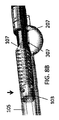
図1A〜図3は、カッターを露出するために屈曲するノーズコーンを含む粥腫切除カテーテル100の例を図示する。粥腫切除カテーテル100は、外側シャフト111を有するカテーテル本体101と、カテーテル本体101の遠位末端のカッター103と、カテーテル本体101の遠位末端のノーズコーン105とを含み得る。さらに、ノーズコーン105は、露出できるカッター103の切断エッジ112を通す切断窓107を含む。ノーズコーン105は、さらに以下で説明されるように、ヒンジ点1109周りにカテーテル本体101の縦軸から離れて屈曲するように構成されうる。この屈曲は、切断窓107を通してカッター103を露出させ、及び/又は、カッター103を、粥腫切除カテーテルが挿入された血管の壁に半径方向に押し付けることができる。
1A-3 illustrate an example of
図1A〜2Cを参照すると、カッター103は、ブッシング155を経由してカテーテル本体101とノーズコーン105との間に配置されうる。実施形態によっては、カッター103は、鋭利な遠位エッジ112を有する輪状カッターであり得る。カッター103は、カッター103を回転するように構成された駆動シャフト113に取り付けられ得る。
Referring to FIGS. 1A-2C,
さらに、また図2A及び2Bを参照すると、粥腫切除カテーテル100は、カッター103内部で、カッター103の切断エッジ112より近位にOCT撮像要素等の撮像要素192を含み得る。撮像要素192は、OCT信号を伝達するために、駆動シャフト113を通す等の方法で、細長い本体の中心を通した軸上に実質上延伸する光ファイバ197を含み得る。さらに、光ファイバ197は、屈曲なしにカテーテル本体101全体を通して真っ直ぐに延伸し得る。光ファイバ197は、カッター103のスロット177でのように、カッター103の遠位末端で取り付けられ得る。そのスロットは、光ファイバ197に、例えば、カテーテル本体101及びカッター103の長さを通して屈曲なしに軸上にとどまらせられるように、少なくともカッター103の中央まで延伸する長さを有する。カッター103への取り付けは別にして、光ファイバ197は、カテーテル本体又は駆動シャフト113内を自由に浮遊しうる。他の実施形態で、光ファイバ197は、駆動シャフト113にその長さに沿って取り付けられ得る。
Additionally, and with reference to FIGS. 2A and 2B, the
図2A〜2Cに示すように、撮像要素192は、ミラーのような、反射要素199を含み得る。反射要素199は、(切断窓を通して)隣接した組織に、光ファイバ197からの光を半径方向に指向するために、カッター103のスロット177内に配置され得る。反射要素199は、組織に光を反射させるために、角度35〜55°、例えば、角度45°のような、光ファイバ197の軸に対して角度をもって配置されている。光ファイバ197の遠位末端は、切断エッジから1mm以下のように、0.5mm以下のように、切断エッジから3mm以下に配置され得る。切断エッジの近傍に撮像要素192を有することによって、結果の画像は、切断される血管の部分と有利に位置を合わせることができる。
As shown in FIGS. 2A-2C,
使用時に、外側シャフト111は、切断窓107、カッター103及び/又は撮像要素192を望ましい位置に配置するために、手動での回転等の方法で、回転させられるように構成され得る。駆動シャフト113は、そのとき、カッター103及び撮像要素142を回転させるために、回転され得る。カッターの回転は、切断エッジの回転運動による切断を提供でき、撮像要素を経由して血管を撮像するために必要な回転を提供することができる。駆動シャフトは、一方向に、およそ1000rpmのように、2000rpmまでの範囲で回転され得るが逆回転やさらなる高速・低速も可能である。
In use, the
図2A〜2Cを参照すると、駆動シャフト113は、さらに、軸方向で、近位及び/又は遠位の方向に変換できるように構成され得る。駆動シャフト113の軸方向の動作は、カッター103の切断エッジ112を露出し又は隠し及び保護するために、ヒンジ点1109(例えば、ブッシング155のピン)周りにノーズコーン105を開く及び/又は閉じることができる。例えば、ブッシング155は、半径方向に内側に延伸した内側フランジ170を含み得る。内側フランジ170は、ヒンジ点1109の遠位に配置され得る。ブッシング155は、さらに、遠位末端から近位末端に向かって内側半径方向に角度を有する、傾斜した外側遠位表面143を含み得る。最後には、カッター103は、近位エッジ166と、駆動シャフト113からカッター103の頭部まで狭くなっていくテーパー状ネック168とを含み得る。これらの様々な要素の相互作用により、ノーズコーン105を開閉することができる。
With reference to FIGS. 2A-2C,
一実施形態で、駆動シャフト113の近位への引き戻しは、カッターを露出するようにノーズコーン105を開く。例えば、駆動シャフト113が近位に引かれると、カッター103の近位エッジ166は、ブッシング155の傾斜した遠位表面143に対して押し付けられる。傾斜した遠位表面143は、遠位末端から近位末端まで半径方向内側に角度がつけられているので、カッター103は、ブッシング155と、さらにノーズコーン105とをカテーテル本体101の縦軸から離れて屈曲させ、その結果、ノーズコーン105を開く(図2Aから2Bへの及び図2Bから2Cへの推移を参照)。切断窓107は、ノーズコーン105が屈曲したときにカッター103がノーズコーン105から突き出せるために、カッター103及び切断エッジ112の直径より大きい開口部を有しうる。
In one embodiment, proximal pulling back of the
一実施形態で、駆動シャフト113の遠位への動作は、ノーズコーン105を閉じる。例えば、図2A〜2Cに示すように、駆動シャフト113が遠位に押されるときに、カッター103のテーパー状ネック168は、相応に、遠位に移動する。テーパー状ネック168の遠位への動作は、ブッシング155の内側フランジ170に、テーパー状ネック168の拡大するエッジに沿って引き摺らせ、ブッシング155を引き起こさせ、相応してノーズコーン105を閉じる(図2Cから図2B及び図2Bから図2Aの推移を参照)。ヒンジ点は内側フランジ170に対して近位であるので、ノーズコーンの完全な閉鎖を許す機械的利点が得られる。
In one embodiment, the distal movement of
図7A〜7Dは、ブッシング155の拡大図を図示する。図示するように、ブッシング155は、二つの交差するチャネル721,723を含み得る。チャネル721,723は、ノーズコーンが開いた構成(チャネル723)及び閉じた構成(チャネル721)にあるときに、撮像サブアセンブリのネック部168をその中に保持するように構成される。チャネル721は、チャネル723がチャネル721に対してある角度で延伸し、それと共に重複する間に、ブッシング155の長い遠位から近位への軸を通して延伸する。ブッシング155は、さらに、旋回点1109を提供するようにトップ周辺部位を通して形成されるヒンジチャネル745を含み得る。ヒンジチャネル745は、チャネル721に対して横軸である。
7A-7D illustrate enlarged views of the
ノーズコーンの開閉の他のメカニズムも可能である。例えば、図4A〜4Dに図示されるように、一実施形態で、(開閉メカニズムを除いてカテーテル100と似た特徴を有する)カテーテル200は、近位末端から遠位末端までの切断窓107に向かって曲がっている、ブッシング155のカムスロット228を含み得る。さらに、カム部材290は、カッター103に取り付けられ、カムスロット228を通して延伸するように構成され得る。駆動シャフト113、及び続いてカム部材290が遠位に押されると、カム部材290は、屈曲したカムスロット228内を動く。屈曲したカムスロット228内のカム部材290の動作は、ブッシング155、及び順にノーズコーン150を下に落とす。逆に、ノーズコーンを閉めるために、駆動シャフト113は、近位に引き寄せられ、その結果、カム部材290に、カムスロット228内に支えさせ、ブッシング155を細長い本体101と一直線になるように引き戻させる。
Other mechanisms for opening and closing the nose cone are also possible. For example, as illustrated in FIGS. 4A-4D, in one embodiment, the catheter 200 (having features similar to the
粥腫切除カテーテル400a,bのノーズコーンの開閉の他のメカニズムは、図11A〜11B及び図12A〜12Bに図示される。カテーテル400a,bは、ブッシング455a,bの外側遠位表面443a,bが、図11Bに示すように本装置の縦軸に対して(角度αが90°であるように)垂直であるか、図12Bに示すように遠位末端から近位末端に向かって(角度αが90°以上であり、縦軸に対するその角度が90°以下であるように)外側半径方向に傾斜しているかのどちらかであることを除いてカテーテル100と同じ特徴を有しうる。図12A〜12Bの本実施形態で、接触点がブッシング455bの内部ラジアルエッジ444のみであるように、角度のついた空間がカッターの近位エッジ166と遠位表面443bとの間に設けられる。カテーテル400aは、カテーテル100を参照した説明と同様に開閉しうる。しかしながら、カテーテル500bは、駆動シャフト113が近位に引き寄せられるときに、全表面443が相互作用するのとは対照的に、最も内側のラジアルエッジ444のみがカッター103の近位エッジ166と相互作用するという点でわずかに異なりながら開く。そのような構成は、ノーズコーン105を開く間の摩擦を好都合に減少させ得る。複数の実施形態で、近位エッジ166は、カテーテルの縦軸に対して角度を持つことができる。そのような場合で、ブッシング455の対向する表面443は、近位エッジ166に対して平行であるか、角度(鋭角又は鈍角)を有するかのいずれかであり得る。
Another mechanism for opening and closing the nosecone of the
図3を参照すると、粥腫切除カテーテル100(又は200若しくは400)は、さらに、軸方向に駆動シャフトを動かすことによってノーズコーン内に組織を詰めるためのメカニズムを含み得る。一実施形態で、遠位への駆動シャフトの動作は、ノーズコーン105を閉じる。駆動シャフト113のさらなる遠位への動作は、カッター103を(すなわち、窓107の遠位エッジに対して)受動的な位置に動かす。受動的な位置では、カッター103は、使用時に血管の望ましくない切断を防止するために窓107のエッジによって保護されうる。駆動シャフト113のさらなる遠位への動作は、カッター103をノーズコーン105内に移動させ、さらに、図3に示すように、カッター103の遠位表面をもって組織を詰める。カッター103は、組織を詰めるためにノーズコーン105内に、1インチ以上又は2インチ以上のように、0.5インチ以上移動することが可能である。複数の実施形態で、ノーズコーン105は、パノラマOCT画像がその中を通して撮像できるように、(例えば、非金属の)OCT的に非遮光的である材料で形成される。
Referring to FIG. 3, the atherectomy catheter 100 (or 200 or 400) may further include a mechanism for packing tissue in the nose cone by moving the drive shaft axially. In one embodiment, distal movement of the drive shaft closes the
図16A〜16Bを参照すると、複数の実施形態で、ブッシング1655は、上記で説明されるブッシングの全ての特徴を含み得るが、内周にそこから切り込まれ、近位末端から遠位末端に向かって延伸するジェットチャネル1785a,bをさらに含み得る。ジェットチャネル1785a,bは、細長い本体101内の流体ラインをノーズコーン105に連結しうる。ジェットチャネル1785a,bを通して流れる液体は速度を増加させ、このようにして、切り取ったマテリアルを詰め、且つ、ノーズコーン内の撮像部分をきれいにするために必要な力を提供する。さらに、ジェットチャネルは、ブッシング1655の遠位末端でのベンチュリ効果を創出することができる。当該ベンチュリ効果は、ノーズコーン内に及び/又は細長い本体の撮像/切断ヘッド並びに/若しくは遠位末端部分から離して、マテリアルを吸い込むことができる。
Referring to FIGS. 16A-16B, in embodiments, the
一実施形態で、粥腫切除カテーテル100(又は200若しくは400)は、カテーテルをガイドするために使用されるモノレールのような、ノーズコーン105でガイドワイヤ内腔を含む。ガイドワイヤ内腔は、撮像時にマーカーとしてうまく使用されうる。
In one embodiment, the atherectomy catheter 100 (or 200 or 400) includes a guidewire lumen with a
粥腫切除カテーテル100,200又は400の複数の実施形態で、図1A及び2A〜2Cに示すように、ノーズコーン105に切断窓107の反対側に一以上の小さな撮像窓207,307が配置され得る。これらのさらなる撮像窓207は、撮像時に、180°にも及ぶ視界を提供することができる。さらに、ノーズコーンが開いたときに一セットの窓207が、より近位に配置され、カッター103及び撮像要素192と軸方向に一直線に構成され得る。しかし一方、ノーズコーンが閉じ、カッター103が受動的な位置にあるときに他セットの窓307が、より遠位に配置され、カッター103及び撮像要素192と軸方向に一直線に構成され得る。複数の実施形態で、撮像窓307,207は、結果となるOCT画像でさらにカッターの位置を特定することを助けるために互いに異なる形状を有する。
In several embodiments of
図8A〜11Bを参照すると、本装置を有するOCT画像カテーテルは、三つの異なる構成での撮像装置の配置(開いたノーズコーン、切断位置でのカッターと共に閉じたノーズコーン、パッキング位置でのカッターと共に閉じたノーズコーン)に依存して変化する。それに応じて、ユーザは、単純に撮像画像を見ることによって、ノーズコーン105が動いているかどうか、カッター103が切断位置又はパッキング位置にいるかどうかを特定することができる。
With reference to FIGS. 8A-11B, an OCT imaging catheter having the present device may be arranged with imaging devices in three different configurations (open nose cone, closed nose cone with cutter in cutting position, cutter in packing position) Change depending on the closed nose cone). Accordingly, the user can specify whether the
例えば、図8Aは、カッター103(及び、それに応じて、撮像センサ)が図8Bに示されるように切断位置にあるときの血管周りのパノラマ画像800を示す。ノーズコーン105の壁は、画像800で円形の外観808として表示される。さらに、ノーズコーン105は透明な材料で形成されるため、血管組織806はノーズコーン105を通してさえも撮像されうる。画像800で参照できるように、180°の視界はこのようにして取得されうる。画像における円形の人工物803(及び、半径方向のライン801)は、ノーズコーン105と並行して延びるガイドワイヤ及び/又はガイドワイヤチャネルに相当する。
For example, FIG. 8A shows a
画像800と比較して、図9Aは、図9Bに示すように、カッター103が受動的な位置にあり、ノーズコーン105が閉じているときのパノラマ画像900を示す。閉じたノーズコーン909が、画像(ライン909a,bがブッシングの壁に相当する)の左側に示されるのに対して、血管組織906の180°の視界は、(窓107を通して撮影された)画像の右側に示される。組織906が画像の左側に見ることができるライン909a,b間の空間913は、ブッシングのさらなる窓307を通して撮影される。さらに、画像900における矢印の間の距離は、先端チップが「閉じている」(及びカテーテルの正中線に近い、結果として近い)ことを示している。
In comparison to image 800, FIG. 9A shows a
最終的に、画像900と比較して、図10Aは、図10Bに示すように、カッター103が切断位置にあり、ノーズコーン105が開いているときの血管周りのパノラマ画像1000を示す。閉じたノーズコーン1009が画像(ライン1009a,bはブッシングの壁に対応する)の左側に示されるのに対して、(窓107を通して撮影された)血管組織1006は、画像の右側に示される。組織1006が見ることができるライン1009a,b間の空間1013は、窓207を通して撮像される。図9A及び図10Aにおける矢印の間の相対的な距離の比較は、カテーテル本体とノーズコーンとの間の増加した距離を示し、したがって、ノーズコーン105が開いた位置にあることをオペレータに示唆する。さらに、複数の実施形態で、ノーズコーンが開いた又は閉じたときに、窓207/307に起因する画像は、窓207/307及び撮像要素297の間の角度変化と窓207/307の異なった形状とのために異なって見える。
Finally, compared to the
一実施形態で粥腫切除カテーテル100(又は200若しくは400)は、カッター103の近くに出水口を含む。出水口は、撮像部位に液体の出水を供給するために使用され、このようにして、画像の質を改善させる。複数の実施形態で、出水は本装置のハンドルのメカニズムを通して活性化されうる。液体は、例えば、カテーテル本体101と駆動シャフト113との間の環状空間において出水されうる。さらに、ブッシングのジェットチャネルを有する実施形態で、環状空間は、液体を供給するために、ジェットチャネルと連結されうる。
In one embodiment, the atherectomy catheter 100 (or 200 or 400) includes a water outlet near the
図6を参照すると、複数の実施形態で、粥腫切除カテーテル100,200,400は、組織にカッター103を押し当てるのを補助するように構成される二以上のバルーンをさらに含む。第1バルーン333は、最遠位のバルーンであり得る。第1バルーン333は、ヒンジ点1109に近位に且つ切断窓1107とは反対側に配置され得る。バルーン333は、組織まで及びその内部にカッター103を屈曲させることによって、組織に対してカッター103を押し付けることができる。遠位バルーン333に近位の第2バルーン335は、切断窓107とカテーテル100の同じ側にあり、さらに、組織内にカッター103を押し当てるのを補助する。複数の実施形態で、第2バルーン335は環状であり得る。複数の実施形態で、第2バルーン335は、血管を閉塞するのを補助し得る。さらに、複数の実施形態で(及び図6に示されるように)第3バルーン337は、閉塞のために使用されうる。一以上のバルーン333,335,337は、2psi以下のような、小さい圧力で膨張するように構成され得る。この低圧力は、バルーン333,335,337が血管壁に対して激しく押圧することを好都合に防止するが、また、組織にカッター103を押し当てるのに十分な圧力を供給する。バルーン333,335,337は、さらに、バルーンに血管に沿ってスライド及び/又は曲がりくねった部分にフィットさせるように近位及び遠位エッジ上にテーパーエッジを含み得る。
Referring to FIG. 6, in some embodiments, the
図17A〜17Dを参照すると、他の実施形態で、粥腫切除カテーテル100,200,400は、カッター103を組織内に押し当て、画像を改善するために血流を閉塞するように構成される単一のバルーンを含み得る。図17Aを参照すると、バルーン1733は、三日月形状を有し、つまり、カッター103が露出されたところを除いてカテーテル100の全周をカバーするようにカテーテル100周りに包むことができる。そのような形状を有するバルーン1733を使用することによって、カテーテル100と血管1723との間の隙間は、実質上減少し、視野から血液を移動させるために必要な局部的な出水を不用にしたり、又は、減少させたりする。一実施形態で、三日月形状を作るために、バルーンは、周表面の少なくとも半分をカバーするようにノーズコーン105及び細長い本体101周りに包まれる両末端に幅広いネック部を含む。図17Cは、両末端で結合する幅広いネック部1737を示すのに対して、図17Bは、包まれたバルーンエッジ1735を示す。図17Cは、バルーン1733の長さに及ぶガイドワイヤ内腔1741と共にバルーン1733の内側に含まれる膨張ポート1739を示す。複数の実施形態で、バルーン1733は、駆動シャフトの近位又は遠位の動作を必要とすることなしにノーズコーンを開閉するために使用されうる。
Referring to FIGS. 17A-17D, in another embodiment, the
図5を参照すると、ハンドル300は、カテーテル100,200又は400のための駆動シャフトの回転又は移動を制御するために使用される。近位配置で動作するファイバを必要とすることなしに、例えば、駆動アセンブリ内の光ファイバアセンブリの動作を必要とすることなしに駆動されるときに、ハンドル300は、好都合に光ファイバに遠位及び近位にカッターと共に移動させる。このようにして、ハンドル300は、駆動シャフトの動作の全てを制御するように設計されうる。模範的な駆動シャフト管理システム555は、図5に示される。駆動シャフト管理システム555は、駆動シャフトが高速度で同時に回転すると共に、ユーザに駆動シャフトを遠位又は近位に配置させる。複数の実施形態で、駆動シャフトは、駆動シャフト管理システム555がその最近位位置に配置される前に完全に伸張しているように構成され得る。換言すれば、駆動シャフト管理システム555は、駆動シャフト伸張スプリング556を含み得る。スプリング556は、ユーザがスライド可能なユーザリング557(又はボタン)を近位に配置したときに、駆動シャフトが完全に伸張し、駆動シャフト管理システム555が近位に動作し、スプリング556に圧縮させ、駆動シャフトに制御された引張荷重を適用させるように構成され得る。このファイバ管理システム555は、切断及び撮像部品を適切に配置するために所定の荷重で駆動シャフトを伸張することによって、好都合にカテーテルの性能を向上させ、カテーテルの切断及び撮像を改善する。
Referring to FIG. 5, the
駆動シャフト管理システム555は、さらに下記で説明されたように、駆動アセンブリから生ずるトルクを伝達することができる。駆動アセンブリとの連結は、光コネクタ559で為されうる。トルクは、このようにして、ファイバ架台551を介して駆動キー560に、駆動シャフト管理システム555を介して、それから直接カテーテル駆動シャフト、それに連結して回転しうる全てに、光コネクタ559から伝達されうる。ファイバ架台551は、光ファイバの近位末端を収納し、駆動シャフトシステム内のトルクを伝達する一セットの部品(それはファイバ架台全体を構成する一対の部品)を含み得る。ファイバ架台部品は、設計によって薄壁であり、したがって、内側に中空の空間を作る。ファイバ架台551の中空の空間内で、光ファイバは、装置駆動シャフトが近位又は遠位に配置されると共に挿入され又は引き出され得る。ユーザリング557が近位に配置されるときにファイバがファイバ架台551に挿入される。それと共に、先端チップまでの全長にわたって撮像を維持しつつ、ファイバはファイバ架台551の内側空間内で渦巻き状に動くことができる。逆に、ユーザリング557が遠位に配置されるときに、ファイバがファイバ架台551から引き出される。それと共に、先端チップまでの全長にわたって撮像を維持しつつ、ファイバの巻回部分は真っ直ぐになることができる。この設計の特徴は、好都合に、駆動シャフトシステムが動作できる範囲を増加させるために、さらなるファイバの容量又は駆動シャフトシステム全体への「緩み」を提供する。
Drive
ハンドル300は、さらに、一側面でバルーン膨張内腔に(例えば、前述のようにバルーンを使うために)、バルーン膨張チュービング553に及び/又はポート554にもう一側面で結合するように構成されたバルーン膨張チャンバ552を含み得る。膨張液体はバルーンまでバルーン膨張チャンバ552を通して移動するため、外側シャフト111は、好都合に、バルーン膨張チャンバ552と独立して回転することができ(例えば、ノブ558を回すことにより)、外側シャフト111の回転の間、チュービング553及び/又はポート554を安定状態にする。
The
さらに、図5に示すように、ハンドル300は、上記で説明したように、カテーテルを通して出水を供給するために、カテーテルフラッシュチャンバ663、カテーテルフラッシュチュービング664及び/又は出水口665を含み得る。
Additionally, as shown in FIG. 5, the
ここで説明されるカテーテルは、駆動アセンブリを使用して駆動されうる。模範的な駆動アセンブリは、同時係属中の特許出願:2013年3月15日付のPCT出願 No. PCT / US13 / 32089 「粥腫切除カテーテル駆動アセンブリ」及び2012年10月17日付の米国特許出願 No. 13 / 654,357 「粥腫切除カテーテル及びカテーテルのための非接触動作メカニズム」で説明される。それらの両方は、それらの全ての参照によって組み込まれる。 The catheters described herein can be driven using a drive assembly. An exemplary drive assembly is described in co-pending patent application PCT application No. PCT / US13 / 32089, filed March 15, 2013, "Atherectomy catheter drive assembly" and US patent application No. PCT, filed October 17, 2012. 13/654, 357 "Non-Contact Operating Mechanism for Atherectomy Catheters and Catheters". Both of them are incorporated by all their references.
好都合に、ここで説明される粥腫切除カテーテル100,200,400は、組織の細長い一片を除去するために使用される。図13Aは、ここで説明される粥腫切除カテーテルによって組織から切断されたマテリアルの単一の細長い一片の除去を示す。図13B及び13Cは、除去された組織(重さ70.4mg)の長さを示す。
Advantageously, the
ここで説明される粥腫切除カテーテルは、さらに、後述する同時係属中の出願:2013年3月15日付のPCT出願 No. PCT / US2013/031901 「撮像付き粥腫切除カテーテル」及び2013年3月15日付けのPCT出願 No. PCT / US2013/032494 「撮像付きバルーン粥腫切除カテーテル」で説明される任意の特徴を含んでいてもよい。その両方は、それらの全てにおいて、ここに参照によって組み込まれる。 The atherectomy catheter described herein is further described in co-pending application described below: PCT Application No. PCT / US2013 / 031901 dated March 15, 2013 "Atherectomy catheter with imaging" and March 2013 PCT Application No. PCT / US2013 / 032494, dated May 15, may include any of the features described in "The balloon atherectomy catheter with imaging." Both of them are incorporated herein by reference in all of them.
[閉塞横断カテーテル]
図14を参照すると、閉塞横断カテーテル700は、そこに取り付けられたテーパー状の閉塞バルーン535付きの外側シース511を含み得る。
[Occlusion crossing catheter]
Referring to FIG. 14, an
複数の実施形態で、カテーテル700の切断ヘッド503は、取り換え可能であり、本装置をさらに広く使用可能に且つ適合可能にする。例えば、先端503は、(図15Aで先端503aによって示されるような)円錐形で目の粗い先端、(図15Bで先端503bによって示されるような)切断エッジを有する縦溝彫りの先端、(図15Cで先端503cによって示されるような)積極的な切断のため前側に突出した先端を含む先端、及び/又は、(図15Dで先端503dによって示されるような)単一の鋭い刃を有するノミのような先端の間で取り換え可能である。先端を交換可能にするために、先端503は、例えば、ヘッド503の回転の反対方向にネジ切りされたネジ型近位エッジを有する。他の実施形態で、近位エッジは装置700の細長い本体501にスナップ式に着脱する。
In embodiments, the cutting
[追加の詳細]
上記で言及されるように、ここで説明される本装置及び技術は、OCTイメージングで使用されうる。模範的な撮像システムは、同時係属中の出願:2010年5月28日付の米国特許出願 No. 12 / 790,703 「生物学的イメージングのための光コヒーレンストモグラフィ」、公開公報No. US-2010-0305452-A1;2010年7月1日付の米国特許出願 No. 12 / 829,267 「カテーテルに基づいた軸外の光コヒーレンストモグラフィイメージングシステム」、公開公報No. US-2010-0021926-A1;2013年3月15日付の国際特許出願「生物学的イメージングのためのグレーデッドインデックスファイバを用いた光コヒーレンストモグラフィ」、公開公報No. WO-2013-172972で説明される。それらの全ては、それらの全てに参照によって組み込まれる。
[Additional details]
As mentioned above, the present apparatus and techniques described herein may be used in OCT imaging. An exemplary imaging system is described in co-pending application: US Patent Application No. 12 / 790,703, May 28, 2010 "Optical Coherence Tomography for Biological Imaging", published publication No. US-2010- U.S. Patent Application No. 12 / 829,267, July 1, 2010 "Catheter-based off-axis optical coherence tomography imaging system", published publication No. US-2010-0021926-A1; 2013 3 It is described in International Patent Application "Optical Coherence Tomography Using Graded Index Fibers for Biological Imaging", dated May 15th, published on May 15th. All of them are incorporated by reference in all of them.
実施例で使用されるときを含み、他に明示的に明記されていない限り、本明細書及び請求の範囲で使用される場合、用語が明示的に表現されていない場合でさえ、全ての数値は、「約」又は「およそ」という語によって前置きされるように読み取るものとする。「約」又は「およそ」という語は、説明された値及び/又は位置が合理的に期待された範囲内にあることを示すために大きさ及び/又は位置を説明するときに使用されてもよい。例えば、数値は、言明された値(又は値の範囲)の+/−0.1%,言明された値(又は値の範囲)の+/−1%,言明された値(又は値の範囲)の+/−2%,言明された値(又は値の範囲)の+/−5%,言明された値(又は値の範囲)の+/−10%等の値を有してもよい。ここで引用された任意の数値範囲は、その中に包含される全ての下位範囲を含むことが意図される。 As used in the specification and claims, including when used in the Examples and unless explicitly stated otherwise, all numerical values, even when terms are not explicitly stated Shall be read as prefaced by the words "about" or "approximately". The terms "about" or "approximately" are also used in describing size and / or position to indicate that the described value and / or position is reasonably within the expected range. Good. For example, a numerical value may be +/- 0.1% of a stated value (or range of values), +/- 1% of a stated value (or range of values), a stated value (or range of values) Of +/-) of the stated value (or range of values), +/- 5% of the stated value (or range of values), +/- 10% of the stated value (or range of values), etc. . Any numerical range recited herein is intended to include all sub-ranges subsumed therein.
材料及び製造技術を含む本発明に関連のある追加の詳細は、関連する当業者のレベルの範囲内として用いることができる。同じことは、一般的又は論理的に使用される追加の行為の用語で、本発明の方法に基づく態様に関して当てはまることがある。また、説明される本発明の変形例の任意の特徴は、記載され、独立して請求され又はここで説明される特徴の任意の一以上と組み合わせてもよいことが熟考される。同様に、単一の項目への参照は、現在の同じ項目が複数存在する可能性を含んでいる。ことさら特に、ここ及び添付された特許請求の範囲で使用されるように、単数形 "a", "and", "said" 及び "the" は、内容が他を明示的に示さない限り複数の指示対象を含む。特許請求の範囲は任意選択の要素を除外するように草稿されてもよいことをさらに留意すべきである。このように、この記述は、「単に」、「のみ」のような排他的専門用語及びクレーム要素の引用の結合における同類のものの使用又は「消極的な」限定の使用のために先の記載として提供することを目的とする。ここで他に定義しない限り、ここで使用される全ての技術的及び科学的用語は、本発明の属する技術分野における当業者の一人によって共通して理解される同じ意味を有する。本発明の範囲は、ここで説明される実施例によって限定されるものではなく、使用されるクレーム語句の明白な意味によってのみ限定されるものではない。 Additional details related to the present invention, including materials and manufacturing techniques, may be used as within the level of ordinary skill in the relevant art. The same may apply to the method-based aspect of the invention in terms of additional acts commonly or logically used. Also, it is contemplated that any features of the variations of the invention described may be combined with any one or more of the features described, independently claimed, or described herein. Similarly, a reference to a single item includes the possibility that there is more than one of the same current item. In particular, as used herein and in the appended claims, the singular forms "a", "and", "said" and "the" include plural referents unless the context clearly indicates otherwise Including the target of indication. It should further be noted that the claims may be drafted to exclude optional elements. Thus, this description is as described above for the use of the like in the combination of citations of exclusive terminology and claim elements such as "simply", "only" or the use of "passive" limitations. Intended to be provided. Unless defined otherwise herein, all technical and scientific terms used herein have the same meaning as commonly understood by one of ordinary skill in the art to which this invention belongs. The scope of the present invention is not limited by the embodiments described herein, but only by the clear meaning of the claim language used.
100 粥腫切除カテーテル
101 細長い本体
103 カッター
105 ノーズコーン
107 切断窓
111 外側シャフト
112 切断エッジ
113 駆動シャフト
143 遠位表面
150 ノーズコーン
155 ブッシング
166 近位エッジ
168 ネック部、テーパー状ネック
170 内側フランジ
177 スロット
180 カムスロット
192 撮像要素
197 光ファイバ
199 反射要素
200 粥腫切除カテーテル
207 撮像窓
228 カムスロット
290 カム部材
297 撮像要素
300 ハンドル
307 撮像窓
333 第1バルーン、遠位バルーン
335 第2バルーン、支点バルーン
337 第3バルーン
400,400a,b 粥腫切除カテーテル
443 全表面
443a,b 外側遠位表面
444 ラジアルエッジ
455 ブッシング
500,500a,b 粥腫切除カテーテル
501 細長い本体
503 切断ヘッド、先端
535 閉塞バルーン
551 ファイバ架台
552 バルーン膨張チャンバ
553 バルーン膨張チュービング
554 ポート
555 駆動シャフト管理システム、ファイバ管理システム
556 駆動シャフト伸張スプリング
557 ユーザリング
558 ノブ
559 光コネクタ
560 駆動キー
663 カテーテルフラッシュチャンバ
664 カテーテルフラッシュチュービング
665 出水口
700 閉塞横断カテーテル、装置
721,723 チャネル
745 ヒンジチャネル
800 パノラマ画像
801 ライン
803 人工物
806 血管組織
808 外観
900 パノラマ画像
906 血管組織
909 ノーズコーン
909a,b ライン
913 空間
1000 パノラマ画像
1006 血管組織
1009 ノーズコーン
1009a,b ライン
1013 空間
1107 切断窓
1109 旋回点、ヒンジ点
1655 ブッシング
1723 血管
1733 バルーン
1735 バルーンエッジ
1737 ネック部
1741 ガイドワイヤ内腔
1785a,b ジェットチャネル
100 Atherectomy catheter 101 Elongated body 103 Cutter 105 Nose cone 107 Cutting window 111 Outer shaft 112 Cutting edge 113 Drive shaft 143 Distal surface 150 Nose cone 155 Bushing 166 Proximal edge 168 Neck, tapered neck 170 Inner flange 177 Slot 180 cam slot 192 imaging element 197 optical fiber 199 reflective element 200 atherectomy catheter 207 imaging window 228 cam slot 290 cam member 297 imaging element 300 handle 307 imaging window 333 first balloon, distal balloon 335 second balloon, fulcrum balloon 337 Third balloon 400, 400a, b atherectomy catheter 443 all surface 443a, b outer distal surface 444 radial edge 455 bushing 500, 500a, b Atherectomy catheter 501 Elongated body 503 Cutting head, tip 535 Occlusion balloon 551 Fiber mount 552 Balloon base 552 Balloon inflation chamber 553 Balloon inflation tubing 554 Port 555 Drive shaft management system, fiber management system 556 Drive shaft extension spring 557 User ring 558 Knob 559 light Connector 560 drive key 663 catheter flash chamber 664 catheter flash tubing 665 water outlet 700 blockage crossing catheter, device 721, 723 channel 745 hinge channel 800 panoramic image 801 line 803 artifact 806 vascular tissue 808 appearance 900 panoramic image 906 vascular tissue 909 nose cone 909a, b line 913 space 1000 panoramic image 1006 blood vessel tissue 10 9 nose cone 1009a, b line 1013 space 1107 cutting window 1109 pivot point hinge point 1655 bushing 1723 vessels 1733 Balloon 1735 Balloon edge 1737 neck 1741 guidewire lumen 1785A, b jet channel
Claims (11)
前記細長い本体の遠位末端から延伸する中空の先端チップと、
前記細長い本体内を近位から遠位に向けて延伸する駆動シャフトと、
前記細長い本体の一側面と連結されるヒンジ点及び前記ヒンジ点に遠位に配置される半径方向に内側に延伸した内側フランジを有し、前記中空の先端チップと連結されるブッシングと、
遠位切断エッジ及び前記ブッシングを通るテーパー状ネック部を有し、前記駆動シャフトと連結される切断及び撮像アセンブリとを備え、
前記ブッシング内の前記駆動シャフトの遠位の動作は、内側フランジを切断及び撮像アセンブリの前記テーパー状ネック部の拡大するエッジに沿って移動させ、前記ヒンジ点について前記中空の先端チップ及びブッシングを旋回させ、少なくとも部分的に前記遠位切断エッジをカバーするように軸方向に前記中空の先端チップを前記細長い本体と一直線にする、ことを特徴とする粥腫切除カテーテル装置。 An elongated body,
A hollow tip extending from the distal end of the elongated body;
A drive shaft extending proximally to distally within the elongated body;
A hinge point coupled to one side of the elongated body and a radially inwardly extending inner flange disposed distal to the hinge point, the bushing coupled to the hollow tip;
A cutting and imaging assembly having a distal cutting edge and a tapered neck through the bushing and coupled with the drive shaft;
The distal movement of the drive shaft within the bushing moves along the expanding edges of the tapered neck portion of the cutting and imaging assembly inside flange, turning the hollow distal tip and bushing for the hinge points Atherectomy catheter device characterized in that the hollow tip is axially aligned with the elongate body to at least partially cover the distal cutting edge .
Applications Claiming Priority (3)
| Application Number | Priority Date | Filing Date | Title |
|---|---|---|---|
| US201461936837P | 2014-02-06 | 2014-02-06 | |
| US61/936,837 | 2014-02-06 | ||
| PCT/US2015/014613 WO2015120146A1 (en) | 2014-02-06 | 2015-02-05 | Atherectomy catheters and occlusion crossing devices |
Publications (2)
| Publication Number | Publication Date |
|---|---|
| JP2017506100A JP2017506100A (en) | 2017-03-02 |
| JP6539669B2 true JP6539669B2 (en) | 2019-07-03 |
Family
ID=53778440
Family Applications (1)
| Application Number | Title | Priority Date | Filing Date |
|---|---|---|---|
| JP2016550604A Active JP6539669B2 (en) | 2014-02-06 | 2015-02-05 | Atherectomy catheter and crossing obstruction device |
Country Status (7)
| Country | Link |
|---|---|
| US (2) | US9592075B2 (en) |
| EP (1) | EP3102127B1 (en) |
| JP (1) | JP6539669B2 (en) |
| CN (1) | CN106102608B (en) |
| CA (1) | CA2938972A1 (en) |
| MX (1) | MX2016010141A (en) |
| WO (1) | WO2015120146A1 (en) |
Families Citing this family (44)
| Publication number | Priority date | Publication date | Assignee | Title |
|---|---|---|---|---|
| US8644913B2 (en) | 2011-03-28 | 2014-02-04 | Avinger, Inc. | Occlusion-crossing devices, imaging, and atherectomy devices |
| US9498600B2 (en) | 2009-07-01 | 2016-11-22 | Avinger, Inc. | Atherectomy catheter with laterally-displaceable tip |
| US8062316B2 (en) | 2008-04-23 | 2011-11-22 | Avinger, Inc. | Catheter system and method for boring through blocked vascular passages |
| US9125562B2 (en) | 2009-07-01 | 2015-09-08 | Avinger, Inc. | Catheter-based off-axis optical coherence tomography imaging system |
| WO2010129075A1 (en) | 2009-04-28 | 2010-11-11 | Avinger, Inc. | Guidewire support catheter |
| EP2435815B1 (en) | 2009-05-28 | 2023-08-09 | Avinger, Inc. | Optical coherence tomography for biological imaging |
| WO2014039096A1 (en) | 2012-09-06 | 2014-03-13 | Avinger, Inc. | Re-entry stylet for catheter |
| WO2014039099A1 (en) | 2012-09-06 | 2014-03-13 | Avinger, Inc. | Balloon atherectomy catheters with imaging |
| US11382653B2 (en) | 2010-07-01 | 2022-07-12 | Avinger, Inc. | Atherectomy catheter |
| US9949754B2 (en) | 2011-03-28 | 2018-04-24 | Avinger, Inc. | Occlusion-crossing devices |
| EP2768406B1 (en) | 2011-10-17 | 2019-12-04 | Avinger, Inc. | Atherectomy catheters and non-contact actuation mechanism for catheters |
| US9345406B2 (en) | 2011-11-11 | 2016-05-24 | Avinger, Inc. | Occlusion-crossing devices, atherectomy devices, and imaging |
| WO2013172972A1 (en) | 2012-05-14 | 2013-11-21 | Avinger, Inc. | Optical coherence tomography with graded index fiber for biological imaging |
| US11406412B2 (en) | 2012-05-14 | 2022-08-09 | Avinger, Inc. | Atherectomy catheters with imaging |
| WO2013172974A1 (en) | 2012-05-14 | 2013-11-21 | Avinger, Inc. | Atherectomy catheter drive assemblies |
| US9498247B2 (en) | 2014-02-06 | 2016-11-22 | Avinger, Inc. | Atherectomy catheters and occlusion crossing devices |
| US11284916B2 (en) * | 2012-09-06 | 2022-03-29 | Avinger, Inc. | Atherectomy catheters and occlusion crossing devices |
| US9854979B2 (en) | 2013-03-15 | 2018-01-02 | Avinger, Inc. | Chronic total occlusion crossing devices with imaging |
| EP2967367B1 (en) | 2013-03-15 | 2019-02-20 | Avinger, Inc. | Optical pressure sensor assembly |
| EP2967507B1 (en) | 2013-03-15 | 2018-09-05 | Avinger, Inc. | Tissue collection device for catheter |
| JP6517198B2 (en) | 2013-07-08 | 2019-05-22 | アビンガー・インコーポレイテッドAvinger, Inc. | Identification of elastic layers guiding interventions |
| JP6539669B2 (en) | 2014-02-06 | 2019-07-03 | アビンガー・インコーポレイテッドAvinger, Inc. | Atherectomy catheter and crossing obstruction device |
| EP3166512B1 (en) | 2014-07-08 | 2020-08-19 | Avinger, Inc. | High speed chronic total occlusion crossing devices |
| US10568520B2 (en) | 2015-07-13 | 2020-02-25 | Avinger, Inc. | Micro-molded anamorphic reflector lens for image guided therapeutic/diagnostic catheters |
| US11278248B2 (en) | 2016-01-25 | 2022-03-22 | Avinger, Inc. | OCT imaging catheter with lag correction |
| CN108882948A (en) | 2016-04-01 | 2018-11-23 | 阿维格公司 | Rotary-cut art conduit with zigzag cutter |
| WO2017210466A1 (en) | 2016-06-03 | 2017-12-07 | Avinger, Inc. | Catheter device with detachable distal end |
| JP7061080B2 (en) * | 2016-06-30 | 2022-04-27 | アビンガー・インコーポレイテッド | Atherectomy catheter with a shaped distal tip |
| EP3508149A4 (en) | 2016-08-30 | 2020-04-29 | Terumo Kabushiki Kaisha | MEDICAL DEVICE AND TREATMENT METHOD |
| CN106691506A (en) * | 2016-12-29 | 2017-05-24 | 天津恒宇医疗科技有限公司 | OCT imaging conduit with high imaging quality |
| EP3568084A4 (en) * | 2017-01-11 | 2020-04-29 | Carevature Medical Ltd. | Surgical instrument with bended shaft |
| EP3618735B1 (en) * | 2017-05-03 | 2025-03-26 | Medtronic Vascular Inc. | Tissue-removing catheter with guidewire isolation liner |
| US10758268B2 (en) * | 2017-12-12 | 2020-09-01 | Covidien Lp | Surgical instrument including system for sensing tissue properties and methods thereof |
| WO2019204797A1 (en) * | 2018-04-19 | 2019-10-24 | Avinger, Inc. | Occlusion-crossing devices |
| US20210386451A1 (en) * | 2018-11-01 | 2021-12-16 | Koninklijke Philips N.V. | Atherectomy devices including pre-shaped and curved distal portions and methods |
| EP3998969A4 (en) * | 2019-07-15 | 2023-08-02 | Ancora Heart, Inc. | DEVICES AND METHOD FOR BELT CUTTING |
| EP4044943A4 (en) * | 2019-10-18 | 2024-02-14 | Avinger, Inc. | ATHERECTOMY CATHETER WITH A MOLDABLE DISTAL TIP |
| WO2021076356A1 (en) | 2019-10-18 | 2021-04-22 | Avinger, Inc. | Occlusion-crossing devices |
| CN110755133A (en) * | 2019-11-19 | 2020-02-07 | 昆山金泰医疗科技有限公司 | Rotary cutting device |
| US11304723B1 (en) | 2020-12-17 | 2022-04-19 | Avantec Vascular Corporation | Atherectomy devices that are self-driving with controlled deflection |
| CN113017780B (en) * | 2021-03-02 | 2022-03-08 | 哈尔滨医科大学 | Catheter system integrating ultrasonic imaging and rotational atherectomy of plaque in cavity |
| CN113616287B (en) * | 2021-03-30 | 2025-01-21 | 美敦力瓦斯科尔勒公司 | Tissue removal catheter with coupled liner |
| US12239341B2 (en) | 2021-03-30 | 2025-03-04 | Medtronic Vascular, Inc. | Tissue-removing catheter with a coupled inner liner |
| WO2025038964A1 (en) | 2023-08-16 | 2025-02-20 | Avantec Vascular Corporation | Thrombectomy devices with lateral and vertical bias |
Family Cites Families (499)
| Publication number | Priority date | Publication date | Assignee | Title |
|---|---|---|---|---|
| US3908637A (en) | 1974-04-22 | 1975-09-30 | Louis W Doroshow | Rigid urethral instrument |
| DE2733019C3 (en) | 1977-07-21 | 1981-01-15 | Boris Samoilovitsch Gechman | Device for crushing concretions in the ureter |
| US4527553A (en) | 1980-04-28 | 1985-07-09 | Upsher Michael S | Laryngoscope with improved light source |
| US4621353A (en) | 1982-09-09 | 1986-11-04 | Burroughs Corporation | Optical memory system providing improved focusing control and improved beam combining and separating apparatus |
| US4487206A (en) | 1982-10-13 | 1984-12-11 | Honeywell Inc. | Fiber optic pressure sensor with temperature compensation and reference |
| FR2541784B1 (en) | 1983-02-25 | 1986-05-16 | Thomson Csf | DEVICE FOR STATIC DEFLECTION OF AN INFRARED BEAM |
| US4611600A (en) | 1983-11-21 | 1986-09-16 | Cordis Corporation | Optical fiber pressure transducer |
| US5178153A (en) | 1984-03-08 | 1993-01-12 | Einzig Robert E | Fluid flow sensing apparatus for in vivo and industrial applications employing novel differential optical fiber pressure sensors |
| US5041082A (en) | 1986-06-16 | 1991-08-20 | Samuel Shiber | Mechanical atherectomy system and method |
| US4926858A (en) | 1984-05-30 | 1990-05-22 | Devices For Vascular Intervention, Inc. | Atherectomy device for severe occlusions |
| US4552554A (en) | 1984-06-25 | 1985-11-12 | Medi-Tech Incorporated | Introducing catheter |
| US4686982A (en) | 1985-06-19 | 1987-08-18 | John Nash | Spiral wire bearing for rotating wire drive catheter |
| US4654024A (en) | 1985-09-04 | 1987-03-31 | C.R. Bard, Inc. | Thermorecanalization catheter and method for use |
| US5182291A (en) | 1986-02-14 | 1993-01-26 | Sanofi | Pyrozala-pyridyl aminoabkoxyphenol compounds |
| US5000185A (en) | 1986-02-28 | 1991-03-19 | Cardiovascular Imaging Systems, Inc. | Method for intravascular two-dimensional ultrasonography and recanalization |
| US4771774A (en) | 1986-02-28 | 1988-09-20 | Devices For Vascular Intervention, Inc. | Motor drive unit |
| US4691708A (en) | 1986-03-10 | 1987-09-08 | Cordis Corporation | Optical pressure sensor for measuring blood pressure |
| JPH0732758B2 (en) | 1986-05-21 | 1995-04-12 | オリンパス光学工業株式会社 | Endoscope |
| SE453561B (en) | 1986-06-25 | 1988-02-15 | Radisensor Ab | MINIATURIZED SENSOR FOR PHYSIOLOGICAL PRESSURE SEATS |
| US4841977A (en) | 1987-05-26 | 1989-06-27 | Inter Therapy, Inc. | Ultra-thin acoustic transducer and balloon catheter using same in imaging array subassembly |
| US4857046A (en) | 1987-10-21 | 1989-08-15 | Cordis Corporation | Drive catheter having helical pump drive shaft |
| US5047040A (en) | 1987-11-05 | 1991-09-10 | Devices For Vascular Intervention, Inc. | Atherectomy device and method |
| US4920961A (en) | 1988-06-02 | 1990-05-01 | Circon Corporation | System for disconnetably mounting an endoscope sheath with an endoscope tool |
| DE68925757T2 (en) | 1988-06-13 | 1996-09-05 | Samuel Shiber | Atherectomy system with a guidewire |
| SE460396B (en) | 1988-07-29 | 1989-10-09 | Radisensor Ab | MINIATURIZED SENSOR DEVICE FOR SEATING PHYSIOLOGICAL PRESSURE IN VIVO |
| US5099850A (en) | 1989-01-17 | 1992-03-31 | Olympus Optical Co., Ltd. | Ultrasonic diagnostic apparatus |
| US5431673A (en) | 1989-02-17 | 1995-07-11 | American Biomed, Inc. | Distal atherectomy catheter |
| US5226909A (en) | 1989-09-12 | 1993-07-13 | Devices For Vascular Intervention, Inc. | Atherectomy device having helical blade and blade guide |
| US5085662A (en) | 1989-11-13 | 1992-02-04 | Scimed Life Systems, Inc. | Atherectomy catheter and related components |
| US5054501A (en) | 1990-05-16 | 1991-10-08 | Brigham & Women's Hospital | Steerable guide wire for cannulation of tubular or vascular organs |
| US5674232A (en) | 1990-06-05 | 1997-10-07 | Halliburton; Alexander George | Catheter and method of use thereof |
| BE1003189A5 (en) | 1990-07-27 | 1992-01-07 | B A Cosurvey Optics S P R L B | PRESSURE SENSOR. |
| AU668854B2 (en) | 1990-08-06 | 1996-05-23 | Acculase, Inc. | Fiber optic laser catheter and method of use |
| US5142155A (en) | 1991-03-11 | 1992-08-25 | Hewlett-Packard Company | Catheter tip fluorescence-quenching fiber optic pressure sensor |
| US5465147A (en) | 1991-04-29 | 1995-11-07 | Massachusetts Institute Of Technology | Method and apparatus for acquiring images using a ccd detector array and no transverse scanner |
| US6501551B1 (en) | 1991-04-29 | 2002-12-31 | Massachusetts Institute Of Technology | Fiber optic imaging endoscope interferometer with at least one faraday rotator |
| US5956355A (en) | 1991-04-29 | 1999-09-21 | Massachusetts Institute Of Technology | Method and apparatus for performing optical measurements using a rapidly frequency-tuned laser |
| DE69227902T3 (en) | 1991-04-29 | 2010-04-22 | Massachusetts Institute Of Technology, Cambridge | DEVICE FOR OPTICAL IMAGING AND MEASUREMENT |
| US6564087B1 (en) | 1991-04-29 | 2003-05-13 | Massachusetts Institute Of Technology | Fiber optic needle probes for optical coherence tomography imaging |
| US6485413B1 (en) | 1991-04-29 | 2002-11-26 | The General Hospital Corporation | Methods and apparatus for forward-directed optical scanning instruments |
| US6134003A (en) | 1991-04-29 | 2000-10-17 | Massachusetts Institute Of Technology | Method and apparatus for performing optical measurements using a fiber optic imaging guidewire, catheter or endoscope |
| US7074231B2 (en) | 1991-06-13 | 2006-07-11 | Advanced Cardiovascular Systems, Inc. | Convertible mode vascular catheter system |
| US5190050A (en) | 1991-11-08 | 1993-03-02 | Electro-Catheter Corporation | Tip deflectable steerable catheter |
| US5192291A (en) | 1992-01-13 | 1993-03-09 | Interventional Technologies, Inc. | Rotationally expandable atherectomy cutter assembly |
| EP0621761B1 (en) | 1992-01-13 | 1997-04-02 | Schneider (Usa) Inc. | Surgical cutting tool |
| GB9207532D0 (en) | 1992-04-07 | 1992-05-20 | Innovata Biomed Ltd | Medical connection system |
| JPH0627343A (en) | 1992-07-06 | 1994-02-04 | Nippon Telegr & Teleph Corp <Ntt> | Optical fiber juncture for optical fiber amplifier |
| US5312415A (en) | 1992-09-22 | 1994-05-17 | Target Therapeutics, Inc. | Assembly for placement of embolic coils using frictional placement |
| US5383460A (en) | 1992-10-05 | 1995-01-24 | Cardiovascular Imaging Systems, Inc. | Method and apparatus for ultrasound imaging and atherectomy |
| US5333142A (en) | 1992-10-26 | 1994-07-26 | The United States Of America As Represented By The Secretary Of The Navy | Technique for intracavity sum frequency generation |
| US5643297A (en) | 1992-11-09 | 1997-07-01 | Endovascular Instruments, Inc. | Intra-artery obstruction clearing apparatus and methods |
| US5383467A (en) | 1992-11-18 | 1995-01-24 | Spectrascience, Inc. | Guidewire catheter and apparatus for diagnostic imaging |
| US5460168A (en) | 1992-12-25 | 1995-10-24 | Olympus Optical Co., Ltd. | Endoscope cover assembly and cover-system endoscope |
| US5429136A (en) | 1993-04-21 | 1995-07-04 | Devices For Vascular Intervention, Inc. | Imaging atherectomy apparatus |
| CA2161776C (en) | 1993-04-28 | 2005-12-20 | Chandrashekhar P. Pathak | Apparatus and methods for intraluminal photothermoforming |
| US6017359A (en) | 1993-05-25 | 2000-01-25 | Vascular Solutions, Inc. | Vascular sealing apparatus |
| US5951583A (en) | 1993-05-25 | 1999-09-14 | Vascular Solutions, Inc. | Thrombin and collagen procoagulant and process for making the same |
| US5868778A (en) | 1995-10-27 | 1999-02-09 | Vascular Solutions, Inc. | Vascular sealing apparatus and method |
| US5383896A (en) | 1993-05-25 | 1995-01-24 | Gershony; Gary | Vascular sealing device |
| US5579767A (en) | 1993-06-07 | 1996-12-03 | Prince; Martin R. | Method for imaging abdominal aorta and aortic aneurysms |
| US5366464A (en) | 1993-07-22 | 1994-11-22 | Belknap John C | Atherectomy catheter device |
| CH687228A5 (en) | 1993-09-15 | 1996-10-31 | Synthes Ag | Drill head. |
| CA2173482A1 (en) | 1993-10-07 | 1995-04-13 | Erik Andersen | Dilatation catheter |
| US5437284A (en) | 1993-12-30 | 1995-08-01 | Camino Laboratories, Inc. | System and method for in vivo calibration of a sensor |
| US5517998A (en) | 1994-01-24 | 1996-05-21 | Medamicus, Inc. | Closed loop pressure determination system and method for fiber optic pressure transducer system |
| EP0673627B1 (en) | 1994-03-23 | 2000-01-05 | Yasuo Hashimoto | Catheter with optical fiber |
| JP2869020B2 (en) | 1994-03-23 | 1999-03-10 | 康男 橋本 | Cancer treatment device |
| US5507795A (en) | 1994-04-29 | 1996-04-16 | Devices For Vascular Intervention, Inc. | Catheter with perfusion system |
| US6032673A (en) | 1994-10-13 | 2000-03-07 | Femrx, Inc. | Methods and devices for tissue removal |
| US5836957A (en) | 1994-12-22 | 1998-11-17 | Devices For Vascular Intervention, Inc. | Large volume atherectomy device |
| US5632754A (en) | 1994-12-23 | 1997-05-27 | Devices For Vascular Intervention | Universal catheter with interchangeable work element |
| DE19504261A1 (en) | 1995-02-09 | 1996-09-12 | Krieg Gunther | Angioplasty catheter for dilating and / or opening blood vessels |
| US5681336A (en) | 1995-09-07 | 1997-10-28 | Boston Scientific Corporation | Therapeutic device for treating vien graft lesions |
| US6615071B1 (en) | 1995-09-20 | 2003-09-02 | Board Of Regents, The University Of Texas System | Method and apparatus for detecting vulnerable atherosclerotic plaque |
| CA2231425A1 (en) | 1995-09-20 | 1997-03-27 | Texas Heart Institute | Detecting thermal discrepancies in vessel walls |
| US5556405A (en) | 1995-10-13 | 1996-09-17 | Interventional Technologies Inc. | Universal dilator with reciprocal incisor |
| RU2185859C2 (en) | 1995-10-20 | 2002-07-27 | Надим М. Закка | Device for removing stenoses and supporting vascular walls |
| US5907425A (en) | 1995-12-19 | 1999-05-25 | The Board Of Trustees Of The Leland Stanford Junior University | Miniature scanning confocal microscope |
| SE9601541D0 (en) | 1995-11-08 | 1996-04-23 | Pacesetter Ab | Guidewire assembly |
| US5843050A (en) | 1995-11-13 | 1998-12-01 | Micro Therapeutics, Inc. | Microcatheter |
| SE9504334D0 (en) | 1995-12-04 | 1995-12-04 | Pacesetter Ab | Guidewire assembly |
| US5733296A (en) | 1996-02-06 | 1998-03-31 | Devices For Vascular Intervention | Composite atherectomy cutter |
| NL1003172C2 (en) | 1996-05-20 | 1997-11-21 | Cordis Europ | Catheter insertion sheath with occlusion balloon. |
| DE69725651T2 (en) | 1996-06-11 | 2004-07-29 | Roke Manor Research Ltd., Romsey | A catheter tracking system |
| US5795295A (en) | 1996-06-25 | 1998-08-18 | Carl Zeiss, Inc. | OCT-assisted surgical microscope with multi-coordinate manipulator |
| US6080170A (en) | 1996-07-26 | 2000-06-27 | Kensey Nash Corporation | System and method of use for revascularizing stenotic bypass grafts and other occluded blood vessels |
| US6830577B2 (en) | 1996-07-26 | 2004-12-14 | Kensey Nash Corporation | System and method of use for treating occluded vessels and diseased tissue |
| US5779721A (en) | 1996-07-26 | 1998-07-14 | Kensey Nash Corporation | System and method of use for revascularizing stenotic bypass grafts and other blood vessels |
| US6929481B1 (en) | 1996-09-04 | 2005-08-16 | Immersion Medical, Inc. | Interface device and method for interfacing instruments to medical procedure simulation systems |
| US5830145A (en) | 1996-09-20 | 1998-11-03 | Cardiovascular Imaging Systems, Inc. | Enhanced accuracy of three-dimensional intraluminal ultrasound (ILUS) image reconstruction |
| US5904651A (en) | 1996-10-28 | 1999-05-18 | Ep Technologies, Inc. | Systems and methods for visualizing tissue during diagnostic or therapeutic procedures |
| US5722403A (en) | 1996-10-28 | 1998-03-03 | Ep Technologies, Inc. | Systems and methods using a porous electrode for ablating and visualizing interior tissue regions |
| US5872879A (en) | 1996-11-25 | 1999-02-16 | Boston Scientific Corporation | Rotatable connecting optical fibers |
| JPH10161018A (en) | 1996-11-27 | 1998-06-19 | Olympus Optical Co Ltd | Optical system |
| US5899915A (en) | 1996-12-02 | 1999-05-04 | Angiotrax, Inc. | Apparatus and method for intraoperatively performing surgery |
| US6508825B1 (en) | 1997-02-28 | 2003-01-21 | Lumend, Inc. | Apparatus for treating vascular occlusions |
| US6120516A (en) | 1997-02-28 | 2000-09-19 | Lumend, Inc. | Method for treating vascular occlusion |
| US6010449A (en) | 1997-02-28 | 2000-01-04 | Lumend, Inc. | Intravascular catheter system for treating a vascular occlusion |
| US6183487B1 (en) | 1997-03-06 | 2001-02-06 | Scimed Life Systems, Inc. | Ablation device for reducing damage to vessels and/or in-vivo stents |
| US5843103A (en) | 1997-03-06 | 1998-12-01 | Scimed Life Systems, Inc. | Shaped wire rotational atherectomy device |
| US6758854B1 (en) | 1997-05-09 | 2004-07-06 | St. Jude Medical | Splittable occlusion balloon sheath and process of use |
| US6048349A (en) | 1997-07-09 | 2000-04-11 | Intraluminal Therapeutics, Inc. | Systems and methods for guiding a medical instrument through a body |
| US6013072A (en) | 1997-07-09 | 2000-01-11 | Intraluminal Therapeutics, Inc. | Systems and methods for steering a catheter through body tissue |
| US5987995A (en) | 1997-07-17 | 1999-11-23 | Sentec Corporation | Fiber optic pressure catheter |
| GB9717580D0 (en) | 1997-08-19 | 1997-10-22 | Curry Paul | Device for opening blocked tubes |
| US6402719B1 (en) | 1997-09-05 | 2002-06-11 | Cordis Webster, Inc. | Steerable DMR catheter with infusion tube |
| JPH11221229A (en) | 1997-09-24 | 1999-08-17 | Eclipse Surgical Technol Inc | Catheter |
| US6193676B1 (en) | 1997-10-03 | 2001-02-27 | Intraluminal Therapeutics, Inc. | Guide wire assembly |
| US5951482A (en) | 1997-10-03 | 1999-09-14 | Intraluminal Therapeutics, Inc. | Assemblies and methods for advancing a guide wire through body tissue |
| JP2001522631A (en) | 1997-11-07 | 2001-11-20 | プロリフィックス メディカル, インコーポレイテッド | Method and system for treating obstruction in a body lumen |
| US6183432B1 (en) | 1997-11-13 | 2001-02-06 | Lumend, Inc. | Guidewire and catheter with rotating and reciprocating symmetrical or asymmetrical distal tip |
| US6110164A (en) | 1997-12-05 | 2000-08-29 | Intratherapeutics, Inc. | Guideless catheter segment |
| US6027514A (en) | 1997-12-17 | 2000-02-22 | Fox Hollow Technologies, Inc. | Apparatus and method for removing occluding material from body lumens |
| US20050171478A1 (en) | 1998-01-13 | 2005-08-04 | Selmon Matthew R. | Catheter system for crossing total occlusions in vasculature |
| US6231546B1 (en) | 1998-01-13 | 2001-05-15 | Lumend, Inc. | Methods and apparatus for crossing total occlusions in blood vessels |
| US6416527B1 (en) | 1998-01-28 | 2002-07-09 | St. Jude Medical Cardiovascular Group, Inc. | Vessel cutting device |
| US6824550B1 (en) | 2000-04-06 | 2004-11-30 | Norbon Medical, Inc. | Guidewire for crossing occlusions or stenosis |
| US6175669B1 (en) | 1998-03-30 | 2001-01-16 | The Regents Of The Universtiy Of California | Optical coherence domain reflectometry guidewire |
| EP1067869B1 (en) | 1998-03-31 | 2005-11-02 | Transvascular, Inc. | Tissue penetrating cathethers having integral imaging transducers and their methods of use |
| US6666874B2 (en) | 1998-04-10 | 2003-12-23 | Endicor Medical, Inc. | Rotational atherectomy system with serrated cutting tip |
| US6482217B1 (en) | 1998-04-10 | 2002-11-19 | Endicor Medical, Inc. | Neuro thrombectomy catheter |
| US6001112A (en) | 1998-04-10 | 1999-12-14 | Endicor Medical, Inc. | Rotational atherectomy device |
| US6290668B1 (en) | 1998-04-30 | 2001-09-18 | Kenton W. Gregory | Light delivery catheter and methods for the use thereof |
| US6307985B1 (en) | 1998-07-10 | 2001-10-23 | Micro Therapeutics, Inc. | Optical transmission system |
| US6290689B1 (en) | 1999-10-22 | 2001-09-18 | Corazón Technologies, Inc. | Catheter devices and methods for their use in the treatment of calcified vascular occlusions |
| US6440124B1 (en) | 1998-07-22 | 2002-08-27 | Endovasix, Inc. | Flexible flow apparatus and method for the disruption of occlusions |
| US6319227B1 (en) | 1998-08-05 | 2001-11-20 | Scimed Life Systems, Inc. | Automatic/manual longitudinal position translator and rotary drive system for catheters |
| US6106515A (en) | 1998-08-13 | 2000-08-22 | Intraluminal Therapeutics, Inc. | Expandable laser catheter |
| US6241744B1 (en) | 1998-08-14 | 2001-06-05 | Fox Hollow Technologies, Inc. | Apparatus for deploying a guidewire across a complex lesion |
| DE69938250T2 (en) | 1998-09-11 | 2009-03-12 | Joseph A. Pepper Pike Izatt | INTERFEROMETERS FOR OPTICAL COHERENCE DOMAIN REFLECTOMETRY AND OPTICAL COHERENCE TOMOGRAPHY USING NON-RECIPROCAL OPTICAL ELEMENTS |
| US6398755B1 (en) | 1998-10-06 | 2002-06-04 | Scimed Life Systems, Inc. | Driveable catheter system |
| US6228076B1 (en) | 1999-01-09 | 2001-05-08 | Intraluminal Therapeutics, Inc. | System and method for controlling tissue ablation |
| US6134002A (en) | 1999-01-14 | 2000-10-17 | Duke University | Apparatus and method for the rapid spectral resolution of confocal images |
| US6445944B1 (en) | 1999-02-01 | 2002-09-03 | Scimed Life Systems | Medical scanning system and related method of scanning |
| US6855123B2 (en) | 2002-08-02 | 2005-02-15 | Flow Cardia, Inc. | Therapeutic ultrasound system |
| AU3741400A (en) | 1999-03-15 | 2000-10-04 | Prolifix Medical, Inc. | Shielded atherectomy device |
| US6911026B1 (en) * | 1999-07-12 | 2005-06-28 | Stereotaxis, Inc. | Magnetically guided atherectomy |
| US20040044350A1 (en) | 1999-04-09 | 2004-03-04 | Evalve, Inc. | Steerable access sheath and methods of use |
| US6645217B1 (en) | 1999-05-15 | 2003-11-11 | Advanced Cardiovascular Systems, Inc. | Over-the-wire atherectomy catheter |
| US6719769B2 (en) | 1999-11-15 | 2004-04-13 | Cardica, Inc. | Integrated anastomosis tool with graft vessel attachment device and cutting device |
| US6294775B1 (en) | 1999-06-08 | 2001-09-25 | University Of Washington | Miniature image acquistion system using a scanning resonant waveguide |
| US6563105B2 (en) | 1999-06-08 | 2003-05-13 | University Of Washington | Image acquisition with depth enhancement |
| US6546272B1 (en) | 1999-06-24 | 2003-04-08 | Mackinnon Nicholas B. | Apparatus for in vivo imaging of the respiratory tract and other internal organs |
| US6445939B1 (en) | 1999-08-09 | 2002-09-03 | Lightlab Imaging, Llc | Ultra-small optical probes, imaging optics, and methods for using same |
| US7887556B2 (en) | 2000-12-20 | 2011-02-15 | Fox Hollow Technologies, Inc. | Debulking catheters and methods |
| US8328829B2 (en) | 1999-08-19 | 2012-12-11 | Covidien Lp | High capacity debulking catheter with razor edge cutting window |
| US6638233B2 (en) | 1999-08-19 | 2003-10-28 | Fox Hollow Technologies, Inc. | Apparatus and methods for material capture and removal |
| US7713279B2 (en) | 2000-12-20 | 2010-05-11 | Fox Hollow Technologies, Inc. | Method and devices for cutting tissue |
| US7708749B2 (en) | 2000-12-20 | 2010-05-04 | Fox Hollow Technologies, Inc. | Debulking catheters and methods |
| US6299622B1 (en) * | 1999-08-19 | 2001-10-09 | Fox Hollow Technologies, Inc. | Atherectomy catheter with aligned imager |
| US6447525B2 (en) | 1999-08-19 | 2002-09-10 | Fox Hollow Technologies, Inc. | Apparatus and methods for removing material from a body lumen |
| US20030120295A1 (en) | 2000-12-20 | 2003-06-26 | Fox Hollow Technologies, Inc. | Debulking catheters and methods |
| US20030125757A1 (en) * | 2000-12-20 | 2003-07-03 | Fox Hollow Technologies, Inc. | Debulking catheters and methods |
| WO2001015609A1 (en) | 1999-08-31 | 2001-03-08 | Fox Hollow Technologies | Atherectomy catheter with a rotating and telescoping cutter |
| US6687010B1 (en) | 1999-09-09 | 2004-02-03 | Olympus Corporation | Rapid depth scanning optical imaging device |
| DK176336B1 (en) | 1999-12-22 | 2007-08-20 | Asahi Optical Co Ltd | Endoscopic tissue collection instrument |
| US6929633B2 (en) | 2000-01-25 | 2005-08-16 | Bacchus Vascular, Inc. | Apparatus and methods for clot dissolution |
| EP1251348A4 (en) | 2000-01-28 | 2005-01-12 | Asahi Chemical Ind | Photothermic transducing spectroscopic analyzer |
| US6579298B1 (en) | 2000-02-29 | 2003-06-17 | Scimed Life Systems, Inc. | Method and apparatus for treating vein graft lesions |
| US10092313B2 (en) | 2000-04-05 | 2018-10-09 | Boston Scientific Limited | Medical sealed tubular structures |
| US8475484B2 (en) | 2000-04-05 | 2013-07-02 | Medrad, Inc. | Liquid seal assembly for a rotating torque tube |
| US20040243162A1 (en) | 2000-04-05 | 2004-12-02 | Pathway Medical Technologies, Inc. | Interventional catheter assemblies and control systems |
| AU5317301A (en) | 2000-04-05 | 2001-10-23 | Stx Medical Inc | Intralumenal material removal systems and methods |
| US6565588B1 (en) | 2000-04-05 | 2003-05-20 | Pathway Medical Technologies, Inc. | Intralumenal material removal using an expandable cutting device |
| US7344546B2 (en) | 2000-04-05 | 2008-03-18 | Pathway Medical Technologies | Intralumenal material removal using a cutting device for differential cutting |
| US6517528B1 (en) | 2000-04-13 | 2003-02-11 | Scimed Life Systems, Inc. | Magnetic catheter drive shaft clutch |
| US6454717B1 (en) | 2000-04-13 | 2002-09-24 | Scimed Life Systems, Inc. | Concentric catheter drive shaft clutch |
| US6975898B2 (en) | 2000-06-19 | 2005-12-13 | University Of Washington | Medical imaging, diagnosis, and therapy using a scanning single optical fiber system |
| US7555333B2 (en) | 2000-06-19 | 2009-06-30 | University Of Washington | Integrated optical scanning image acquisition and display |
| US6511474B1 (en) | 2000-07-12 | 2003-01-28 | Corpak, Inc. | Bolus for non-occluding high flow enteral feeding tube |
| US6575995B1 (en) | 2000-07-14 | 2003-06-10 | Advanced Cardiovascular Systems, Inc. | Expandable cage embolic material filter system and method |
| US6572643B1 (en) | 2000-07-19 | 2003-06-03 | Vascular Architects, Inc. | Endoprosthesis delivery catheter assembly and method |
| US6853457B2 (en) | 2000-09-04 | 2005-02-08 | Forskningscenter Riso | Optical amplification in coherence reflectometry |
| US6845190B1 (en) | 2000-11-27 | 2005-01-18 | University Of Washington | Control of an optical fiber scanner |
| US6856712B2 (en) | 2000-11-27 | 2005-02-15 | University Of Washington | Micro-fabricated optical waveguide for use in scanning fiber displays and scanned fiber image acquisition |
| US20020072706A1 (en) | 2000-12-11 | 2002-06-13 | Thomas Hiblar | Transluminal drug delivery catheter |
| US20060032508A1 (en) | 2000-12-20 | 2006-02-16 | Fox Hollow Technologies, Inc. | Method of evaluating a treatment for vascular disease |
| US7927784B2 (en) | 2000-12-20 | 2011-04-19 | Ev3 | Vascular lumen debulking catheters and methods |
| US20060235366A1 (en) | 2000-12-20 | 2006-10-19 | Fox Hollow Technologies, Inc. | Method of evaluating a treatment for vascular disease |
| US7699790B2 (en) | 2000-12-20 | 2010-04-20 | Ev3, Inc. | Debulking catheters and methods |
| US20050154407A1 (en) | 2000-12-20 | 2005-07-14 | Fox Hollow Technologies, Inc. | Method of evaluating drug efficacy for treating atherosclerosis |
| US20100121360A9 (en) | 2000-12-20 | 2010-05-13 | Fox Hollow Technologies, Inc | Testing a patient population having a cardiovascular condition for drug efficacy |
| DE60144107D1 (en) | 2000-12-20 | 2011-04-07 | Fox Hollow Technologies Inc | REDUCTION CATHETER |
| US20050222519A1 (en) | 2000-12-20 | 2005-10-06 | Fox Hollow Technologies, Inc. | Debulking catheters and methods |
| US20040167554A1 (en) | 2000-12-20 | 2004-08-26 | Fox Hollow Technologies, Inc. | Methods and devices for reentering a true lumen from a subintimal space |
| IL140780A0 (en) | 2001-01-08 | 2002-02-10 | Gaber Benny | Deflectable guiding apparatus |
| US6503261B1 (en) | 2001-01-17 | 2003-01-07 | Scimed Life Systems, Inc. | Bi-directional atherectomy burr |
| US6497649B2 (en) | 2001-01-21 | 2002-12-24 | University Of Washington | Alleviating motion, simulator, and virtual environmental sickness by presenting visual scene components matched to inner ear vestibular sensations |
| US6760112B2 (en) | 2001-02-17 | 2004-07-06 | Lucent Technologies Inc. | Grin-fiber lens based optical endoscopes |
| US6542665B2 (en) | 2001-02-17 | 2003-04-01 | Lucent Technologies Inc. | GRIN fiber lenses |
| US20020115931A1 (en) | 2001-02-21 | 2002-08-22 | Strauss H. William | Localizing intravascular lesions on anatomic images |
| US6616676B2 (en) | 2001-04-10 | 2003-09-09 | Scimed Life Systems, Inc. | Devices and methods for removing occlusions in vessels |
| US6522452B2 (en) | 2001-04-26 | 2003-02-18 | Jds Uniphase Corporation | Latchable microelectromechanical structures using non-newtonian fluids, and methods of operating same |
| AT503309B1 (en) | 2001-05-01 | 2011-08-15 | Gen Hospital Corp | DEVICE FOR DETERMINING ATHEROSCLEROTIC BEARING BY MEASURING OPTICAL TISSUE PROPERTIES |
| US7616986B2 (en) | 2001-05-07 | 2009-11-10 | University Of Washington | Optical fiber scanner for performing multimodal optical imaging |
| US7329223B1 (en) | 2001-05-31 | 2008-02-12 | Abbott Cardiovascular Systems Inc. | Catheter with optical fiber sensor |
| US6879851B2 (en) | 2001-06-07 | 2005-04-12 | Lightlab Imaging, Llc | Fiber optic endoscopic gastrointestinal probe |
| WO2002100249A2 (en) | 2001-06-13 | 2002-12-19 | Cardiovascular Innovations, Inc. | Apparatus and method for ultrasonically identifying vulnerable plaque |
| US6702744B2 (en) | 2001-06-20 | 2004-03-09 | Advanced Cardiovascular Systems, Inc. | Agents that stimulate therapeutic angiogenesis and techniques and devices that enable their delivery |
| US6728571B1 (en) | 2001-07-16 | 2004-04-27 | Scimed Life Systems, Inc. | Electronically scanned optical coherence tomography with frequency modulated signals |
| EP1441777A4 (en) | 2001-07-17 | 2007-05-30 | Kerberos Proximal Solutions | Fluid exchange system for controlled and localized irrigation and aspiration |
| US20030045835A1 (en) | 2001-08-30 | 2003-03-06 | Vascular Solutions, Inc. | Method and apparatus for coagulation and closure of pseudoaneurysms |
| US6961123B1 (en) | 2001-09-28 | 2005-11-01 | The Texas A&M University System | Method and apparatus for obtaining information from polarization-sensitive optical coherence tomography |
| US7507245B2 (en) | 2001-10-19 | 2009-03-24 | Cardiovascular Systems, Inc. | Rotational angioplasty device with abrasive crown |
| US6749344B2 (en) | 2001-10-24 | 2004-06-15 | Scimed Life Systems, Inc. | Connection apparatus for optical coherence tomography catheters |
| FR2832505B1 (en) | 2001-11-16 | 2008-07-04 | Inst Francais Du Petrole | OPTICAL FIBER REFRACTOMETER |
| FR2832516B1 (en) | 2001-11-19 | 2004-01-23 | Tokendo Sarl | ROTARY ENDOSCOPES WITH A DEVIED DISTAL VIEW |
| US7557929B2 (en) | 2001-12-18 | 2009-07-07 | Massachusetts Institute Of Technology | Systems and methods for phase measurements |
| US7729742B2 (en) | 2001-12-21 | 2010-06-01 | Biosense, Inc. | Wireless position sensor |
| US6947787B2 (en) | 2001-12-21 | 2005-09-20 | Advanced Cardiovascular Systems, Inc. | System and methods for imaging within a body lumen |
| US7493156B2 (en) | 2002-01-07 | 2009-02-17 | Cardiac Pacemakers, Inc. | Steerable guide catheter with pre-shaped rotatable shaft |
| WO2003079272A1 (en) | 2002-03-15 | 2003-09-25 | University Of Washington | Materials and methods for simulating focal shifts in viewers using large depth of focus displays |
| US6869414B2 (en) | 2002-03-22 | 2005-03-22 | Cardiac Pacemakers, Inc. | Pre-shaped catheter with proximal articulation and pre-formed distal end |
| RU2218191C2 (en) | 2002-04-11 | 2003-12-10 | Научно-исследовательский институт радиоэлектроники и лазерной техники Московского государственного технического университета им. Н.Э.Баумана | Endovasal mini robot |
| US20050085708A1 (en) | 2002-04-19 | 2005-04-21 | University Of Washington | System and method for preparation of cells for 3D image acquisition |
| US7738945B2 (en) | 2002-04-19 | 2010-06-15 | University Of Washington | Method and apparatus for pseudo-projection formation for optical tomography |
| US7811825B2 (en) | 2002-04-19 | 2010-10-12 | University Of Washington | System and method for processing specimens and images for optical tomography |
| US20110201924A1 (en) | 2002-04-30 | 2011-08-18 | The General Hospital Corporation | Method and Apparatus for Improving Image Clarity and Sensitivity in Optical Tomography Using Dynamic Feedback to Control Focal Properties and Coherence Gating |
| US6852109B2 (en) | 2002-06-11 | 2005-02-08 | Intraluminal Therapeutics, Inc. | Radio frequency guide wire assembly with optical coherence reflectometry guidance |
| US6891984B2 (en) | 2002-07-25 | 2005-05-10 | Lightlab Imaging, Llc | Scanning miniature optical probes with optical distortion correction and rotational control |
| US20040039371A1 (en) | 2002-08-23 | 2004-02-26 | Bruce Tockman | Coronary vein navigator |
| US7076135B2 (en) | 2002-09-20 | 2006-07-11 | Nippon Telegraph And Telephone Corporation | Optical module and manufacturing method therefor |
| EP1551273A4 (en) | 2002-10-18 | 2011-04-06 | Arieh Sher | Atherectomy system with imaging guidewire |
| US20040147934A1 (en) | 2002-10-18 | 2004-07-29 | Kiester P. Douglas | Oscillating, steerable, surgical burring tool and method of using the same |
| US7493154B2 (en) | 2002-10-23 | 2009-02-17 | Medtronic, Inc. | Methods and apparatus for locating body vessels and occlusions in body vessels |
| US6849064B2 (en) | 2002-10-25 | 2005-02-01 | James S. Hamada | Minimal access lumbar diskectomy instrumentation and method |
| US6867753B2 (en) | 2002-10-28 | 2005-03-15 | University Of Washington | Virtual image registration in augmented display field |
| WO2004068218A2 (en) | 2003-01-24 | 2004-08-12 | University Of Washington | Optical beam scanning system for compact image display or image acquisition |
| US7474407B2 (en) | 2003-02-20 | 2009-01-06 | Applied Science Innovations | Optical coherence tomography with 3d coherence scanning |
| WO2004113962A2 (en) | 2003-03-03 | 2004-12-29 | Montana State University-Bozeman | Miniature confocal optical device, system, and method |
| US7715896B2 (en) | 2003-03-21 | 2010-05-11 | Boston Scientific Scimed, Inc. | Systems and methods for internal tissue penetration |
| US20040254599A1 (en) | 2003-03-25 | 2004-12-16 | Lipoma Michael V. | Method and apparatus for pre-lancing stimulation of puncture site |
| US6934444B2 (en) | 2003-04-10 | 2005-08-23 | Sioptical, Inc. | Beam shaping and practical methods of reducing loss associated with mating external sources and optics to thin silicon waveguides |
| US8246640B2 (en) | 2003-04-22 | 2012-08-21 | Tyco Healthcare Group Lp | Methods and devices for cutting tissue at a vascular location |
| DE10323217A1 (en) | 2003-05-22 | 2004-12-16 | Siemens Ag | Optical coherent tomography system of examination of tissues or organs, has position sensor at tip of catheter and reconstructs volume image based on sectional images and associated position data |
| USD489973S1 (en) | 2003-06-02 | 2004-05-18 | Vascular Solutions, Inc. | Medical device package |
| US7488340B2 (en) | 2003-06-02 | 2009-02-10 | Vascular Solutions, Inc. | Vascular access closure system |
| US6943881B2 (en) | 2003-06-04 | 2005-09-13 | Tomophase Corporation | Measurements of optical inhomogeneity and other properties in substances using propagation modes of light |
| US7150749B2 (en) | 2003-06-13 | 2006-12-19 | Sherwood Services Ag | Vessel sealer and divider having elongated knife stroke and safety cutting mechanism |
| US7311723B2 (en) | 2003-07-11 | 2007-12-25 | University Of Washington | Scanning laser device and methods of use |
| CN1929781A (en) | 2003-08-21 | 2007-03-14 | 依斯克姆公司 | Automated methods and systems for vascular plaque detection and analysis |
| US7608048B2 (en) | 2003-08-28 | 2009-10-27 | Goldenberg Alec S | Rotating soft tissue biopsy needle |
| DE202004021953U1 (en) | 2003-09-12 | 2013-06-19 | Vessix Vascular, Inc. | Selectable eccentric remodeling and / or ablation of atherosclerotic material |
| US7758625B2 (en) | 2003-09-12 | 2010-07-20 | Abbott Vascular Solutions Inc. | Delivery system for medical devices |
| EP2740416B1 (en) | 2003-10-03 | 2021-05-05 | Boston Scientific Limited, an Irish company | Systems for a delivering a medical implant to an anatomical location in a patient |
| WO2005032642A2 (en) | 2003-10-03 | 2005-04-14 | Acumen Medical, Inc. | Expandable guide sheath and apparatus and methods for making them |
| JP2005114473A (en) | 2003-10-06 | 2005-04-28 | Hitachi Medical Corp | Light detection method and biological light-measuring instrument |
| US20070255252A1 (en) | 2003-10-07 | 2007-11-01 | Mehta Bharat A | Embolectomy Catheter |
| CN103181754A (en) | 2003-10-27 | 2013-07-03 | 通用医疗公司 | Method and apparatus for performing optical imaging using frequency-domain interferometry |
| US7901348B2 (en) | 2003-12-12 | 2011-03-08 | University Of Washington | Catheterscope 3D guidance and interface system |
| US20050141843A1 (en) | 2003-12-31 | 2005-06-30 | Invitrogen Corporation | Waveguide comprising scattered light detectable particles |
| DE102004001498B4 (en) | 2004-01-09 | 2008-01-10 | Siemens Ag | Catheter for insertion into a vessel |
| US20050159731A1 (en) | 2004-01-16 | 2005-07-21 | Lee Don W. | Intravascular catheter |
| US7706863B2 (en) | 2004-01-21 | 2010-04-27 | University Of Washington | Methods for assessing a physiological state of a mammalian retina |
| DE102004008370B4 (en) | 2004-02-20 | 2006-06-01 | Siemens Ag | Catheter for performing and monitoring rotablation |
| DE102004008371B4 (en) | 2004-02-20 | 2006-05-24 | Siemens Ag | atherectomy |
| CA2555966C (en) | 2004-03-04 | 2012-07-10 | Straub Medical Ag | Catheter for sucking, fragmenting and removing material extractable from blood vessels |
| JP2005249704A (en) | 2004-03-08 | 2005-09-15 | Fujinon Corp | Tomographic apparatus |
| US20050203425A1 (en) | 2004-03-10 | 2005-09-15 | Phil Langston | Coaxial dual lumen pigtail catheter |
| ATE556644T1 (en) | 2004-03-23 | 2012-05-15 | California Inst Of Techn | FORWARD SCANING IMAGING LIGHT FIBER PROBE |
| US7126693B2 (en) | 2004-03-29 | 2006-10-24 | Carl Zeiss Meditec, Inc. | Simple high efficiency optical coherence domain reflectometer design |
| DE102004015640B4 (en) | 2004-03-31 | 2007-05-03 | Siemens Ag | Apparatus for performing a cutting-balloon intervention with OCT monitoring |
| US20050228428A1 (en) | 2004-04-07 | 2005-10-13 | Afsar Ali | Balloon catheters and methods for manufacturing balloons for balloon catheters |
| US20050251116A1 (en) | 2004-05-05 | 2005-11-10 | Minnow Medical, Llc | Imaging and eccentric atherosclerotic material laser remodeling and/or ablation catheter |
| US7242480B2 (en) | 2004-05-14 | 2007-07-10 | Medeikon Corporation | Low coherence interferometry for detecting and characterizing plaques |
| US7196318B2 (en) | 2004-07-16 | 2007-03-27 | Kin-Man Yip | Fiber-optic sensing system |
| US20060049587A1 (en) | 2004-09-09 | 2006-03-09 | Cornwell Webster R | Tool connector |
| US20060064009A1 (en) | 2004-09-21 | 2006-03-23 | Webler William E | Vessel imaging devices and methods |
| KR101257100B1 (en) | 2004-09-29 | 2013-04-22 | 더 제너럴 하스피탈 코포레이션 | System and Method for Optical Coherence Imaging |
| US7382949B2 (en) | 2004-11-02 | 2008-06-03 | The General Hospital Corporation | Fiber-optic rotational device, optical system and method for imaging a sample |
| DE102005045071A1 (en) | 2005-09-21 | 2007-04-12 | Siemens Ag | Catheter device with a position sensor system for the treatment of a partial and / or complete vascular occlusion under image monitoring |
| EP2278265A3 (en) | 2004-11-24 | 2011-06-29 | The General Hospital Corporation | Common-Path Interferometer for Endoscopic OCT |
| US7803168B2 (en) | 2004-12-09 | 2010-09-28 | The Foundry, Llc | Aortic valve repair |
| US8983582B2 (en) | 2004-12-20 | 2015-03-17 | Advanced Cardiovascular Systems, Inc. | Methods and apparatuses for positioning within an internal channel |
| US7455649B2 (en) | 2005-01-05 | 2008-11-25 | Vascular Solutions, Inc. | Abdominal tissue support for femoral puncture procedures |
| US7450244B2 (en) | 2005-01-12 | 2008-11-11 | University Of Florida Research Foundation, Inc. | Full circumferential scanning OCT intravascular imaging probe based on scanning MEMS mirror |
| US7854755B2 (en) | 2005-02-01 | 2010-12-21 | Boston Scientific Scimed, Inc. | Vascular catheter, system, and method |
| ES2573672T3 (en) | 2005-02-04 | 2016-06-09 | Boston Scientific Scimed Inc. | Needle design for male sling transobturator |
| EP1850735A2 (en) | 2005-02-10 | 2007-11-07 | Lightlab Imaging, Inc. | Optical coherence tomography apparatus and methods |
| US20060190024A1 (en) | 2005-02-24 | 2006-08-24 | Bei Nianjiong | Recovery catheter apparatus and method |
| US7530948B2 (en) | 2005-02-28 | 2009-05-12 | University Of Washington | Tethered capsule endoscope for Barrett's Esophagus screening |
| US20060252993A1 (en) | 2005-03-23 | 2006-11-09 | Freed David I | Medical devices and systems |
| US20060229646A1 (en) | 2005-04-12 | 2006-10-12 | Sparks Kurt D | Forward-directed atherectomy catheter |
| JP2006288775A (en) | 2005-04-12 | 2006-10-26 | Hitachi Medical Corp | System for supporting endoscopic surgery |
| US7794413B2 (en) | 2005-04-19 | 2010-09-14 | Ev3, Inc. | Libraries and data structures of materials removed by debulking catheters |
| US20060264907A1 (en) | 2005-05-02 | 2006-11-23 | Pulsar Vascular, Inc. | Catheters having stiffening mechanisms |
| DE102005021061B4 (en) | 2005-05-06 | 2011-12-15 | Siemens Ag | Method for tomographic imaging of a cavity by optical coherence tomography (OCT) and an OCT device for carrying out the method |
| JP4643361B2 (en) | 2005-05-30 | 2011-03-02 | オリンパス株式会社 | Endoscope treatment tool and endoscope treatment tool system |
| EP1887946A2 (en) | 2005-06-06 | 2008-02-20 | The Board Of Regents, The University Of Texas System | Oct using spectrally resolved bandwidth |
| US8298147B2 (en) | 2005-06-24 | 2012-10-30 | Volcano Corporation | Three dimensional co-registration for intravascular diagnosis and therapy |
| DE102005029897A1 (en) | 2005-06-27 | 2007-01-04 | Siemens Ag | Picture giving procedure with optical coherence tomography catheter for visualizing molecular functional processes in vulnerable plaques of a blood vessel of a patient, comprises producing tomography picture of contrast agent-marked plaque |
| US20080228033A1 (en) | 2005-07-04 | 2008-09-18 | Medizinische Universität Wien | Optical Coherence Tomography Probe Device |
| US7426036B2 (en) | 2005-07-08 | 2008-09-16 | Imalux Corporation | Common path frequency domain optical coherence reflectometer and common path frequency domain optical coherence tomography device |
| US7428053B2 (en) | 2005-07-08 | 2008-09-23 | Imalux Corporation | Common path frequency domain optical coherence reflectometry/tomography device |
| DE102005032961A1 (en) | 2005-07-14 | 2007-01-18 | Siemens Ag | Method and device for generating an image by means of optical coherence tomography |
| US20070038173A1 (en) | 2005-07-27 | 2007-02-15 | Fox Hollow Technologies, Inc. | Methods affecting markers in patients having vascular disease |
| US7844348B2 (en) | 2005-08-09 | 2010-11-30 | Greatbatch Ltd. | Fiber optic assisted medical lead |
| US20070088230A1 (en) | 2005-09-06 | 2007-04-19 | Fmd Co., Ltd | Medical instrument and medical equipment for treatment, and rotational handle device |
| DE102005045088B4 (en) | 2005-09-21 | 2007-05-16 | Siemens Ag | Optical coherence tomography system |
| DE102005048892B4 (en) | 2005-09-22 | 2009-01-15 | Siemens Ag | Device for carrying out rotablation and medical treatment device |
| JP2009510445A (en) | 2005-09-29 | 2009-03-12 | バイオプティジェン,インコーポレイテッド | Portable optical coherence tomography (OCT) apparatus and related systems |
| JP4545696B2 (en) | 2005-09-30 | 2010-09-15 | 富士フイルム株式会社 | Optical probe |
| US20070078500A1 (en) | 2005-09-30 | 2007-04-05 | Cornova, Inc. | Systems and methods for analysis and treatment of a body lumen |
| JP2007101249A (en) | 2005-09-30 | 2007-04-19 | Fujifilm Corp | Optical tomographic imaging method and apparatus |
| WO2007044612A2 (en) | 2005-10-07 | 2007-04-19 | Bioptigen, Inc. | Imaging systems using unpolarized light and related methods and controllers |
| JP4850495B2 (en) | 2005-10-12 | 2012-01-11 | 株式会社トプコン | Fundus observation apparatus and fundus observation program |
| US8047996B2 (en) | 2005-10-31 | 2011-11-01 | Volcano Corporation | System and method for reducing angular geometric distortion in an imaging device |
| US20070106147A1 (en) | 2005-11-01 | 2007-05-10 | Altmann Andres C | Controlling direction of ultrasound imaging catheter |
| US7728985B2 (en) | 2005-11-14 | 2010-06-01 | Imalux Corporation | Polarization-sensitive common path optical coherence reflectometry/tomography device |
| JP2007135947A (en) | 2005-11-21 | 2007-06-07 | Fujifilm Corp | Optical probe and optical tomographic imaging system |
| JP2009516568A (en) | 2005-11-23 | 2009-04-23 | ユニヴァーシティ オブ ワシントン | Scanning a beam with variable sequential framing using interrupted scanning resonances |
| DE102005059262B4 (en) | 2005-12-12 | 2008-02-07 | Siemens Ag | catheter device |
| WO2007149603A2 (en) | 2006-02-01 | 2007-12-27 | The General Hospital Corporation | Apparatus for applying a plurality of electro-magnetic radiations to a sample |
| US7989207B2 (en) | 2006-02-17 | 2011-08-02 | Tyco Healthcare Group Lp | Testing lumenectomy samples for markers of non-vascular diseases |
| JP4454030B2 (en) | 2006-02-21 | 2010-04-21 | 国立大学法人 筑波大学 | Image processing method for three-dimensional optical tomographic image |
| US9561078B2 (en) | 2006-03-03 | 2017-02-07 | University Of Washington | Multi-cladding optical fiber scanner |
| US7785286B2 (en) | 2006-03-30 | 2010-08-31 | Volcano Corporation | Method and system for imaging, diagnosing, and/or treating an area of interest in a patient's body |
| US7846175B2 (en) | 2006-04-03 | 2010-12-07 | Medrad, Inc. | Guidewire and collapsable filter system |
| DE102006016957B4 (en) | 2006-04-11 | 2010-04-22 | Vimecon Gmbh | laser applicator |
| MY144980A (en) | 2006-04-17 | 2011-12-15 | Univ Sains Malaysia | Method for rapid detection of lymphatic filariasis |
| US8808310B2 (en) | 2006-04-20 | 2014-08-19 | Integrated Vascular Systems, Inc. | Resettable clip applier and reset tools |
| WO2007131078A2 (en) | 2006-05-04 | 2007-11-15 | Centocor, Inc. | Inflammatory condition progression, diagnosis and treatment monitoring methods, systems, apparatus, and uses |
| US20070270647A1 (en) | 2006-05-19 | 2007-11-22 | Ams Research Corporation | Handle for Multifunction Endoscope |
| US20070276419A1 (en) | 2006-05-26 | 2007-11-29 | Fox Hollow Technologies, Inc. | Methods and devices for rotating an active element and an energy emitter on a catheter |
| US20070288036A1 (en) | 2006-06-09 | 2007-12-13 | Niranjan Seshadri | Assembly for crossing a chronic total occlusion and method therefor |
| US20080045986A1 (en) | 2006-06-30 | 2008-02-21 | Atheromed, Inc. | Atherectomy devices and methods |
| US8920448B2 (en) | 2006-06-30 | 2014-12-30 | Atheromed, Inc. | Atherectomy devices and methods |
| JP5220007B2 (en) | 2006-06-30 | 2013-06-26 | アセロメッド, インコーポレイテッド | Apparatus and method for atherectomy |
| US8007506B2 (en) | 2006-06-30 | 2011-08-30 | Atheromed, Inc. | Atherectomy devices and methods |
| US8628549B2 (en) | 2006-06-30 | 2014-01-14 | Atheromed, Inc. | Atherectomy devices, systems, and methods |
| US9314263B2 (en) | 2006-06-30 | 2016-04-19 | Atheromed, Inc. | Atherectomy devices, systems, and methods |
| US9492192B2 (en) | 2006-06-30 | 2016-11-15 | Atheromed, Inc. | Atherectomy devices, systems, and methods |
| US20090018566A1 (en) | 2006-06-30 | 2009-01-15 | Artheromed, Inc. | Atherectomy devices, systems, and methods |
| JP4984706B2 (en) | 2006-07-19 | 2012-07-25 | 株式会社デンソー | Manufacturing method of microstructure |
| US20080033396A1 (en) | 2006-08-01 | 2008-02-07 | Percutaneous Systems, Inc. | Vascular sheaths and methods for their deployment |
| US7674253B2 (en) | 2006-08-18 | 2010-03-09 | Kensey Nash Corporation | Catheter for conducting a procedure within a lumen, duct or organ of a living being |
| US20080058629A1 (en) | 2006-08-21 | 2008-03-06 | University Of Washington | Optical fiber scope with both non-resonant illumination and resonant collection/imaging for multiple modes of operation |
| US7538886B2 (en) | 2006-08-22 | 2009-05-26 | Imalux Corporation | Common path time domain optical coherence reflectometry/tomography device |
| EP1892501A3 (en) | 2006-08-23 | 2009-10-07 | Heliotis AG | Colorimetric three-dimensional microscopy |
| WO2008023741A1 (en) | 2006-08-24 | 2008-02-28 | Terumo Kabushiki Kaisha | Coupling device, auxiliary device and adaptor fixing member |
| JPWO2008029506A1 (en) | 2006-09-04 | 2010-01-21 | 学校法人北里研究所 | Optical coherence tomography device |
| US7821643B2 (en) | 2006-09-06 | 2010-10-26 | Imalux Corporation | Common path systems and methods for frequency domain and time domain optical coherence tomography using non-specular reference reflection and a delivering device for optical radiation with a partially optically transparent non-specular reference reflector |
| US20080065205A1 (en) | 2006-09-11 | 2008-03-13 | Duy Nguyen | Retrievable implant and method for treatment of mitral regurgitation |
| US7840283B1 (en) | 2006-09-21 | 2010-11-23 | Pacesetter, Inc. | Bipolar screw-in lead |
| US8068921B2 (en) | 2006-09-29 | 2011-11-29 | Vivant Medical, Inc. | Microwave antenna assembly and method of using the same |
| US7824089B2 (en) | 2006-10-03 | 2010-11-02 | Alcon, Inc. | Gradient index surgical illuminator |
| WO2008042987A2 (en) | 2006-10-04 | 2008-04-10 | Pathway Medical Technologies, Inc. | Interventional catheters |
| US8394078B2 (en) | 2006-10-04 | 2013-03-12 | Medrad, Inc. | Interventional catheters incorporating an active aspiration system |
| US7878983B2 (en) | 2006-10-26 | 2011-02-01 | Wilson-Cook Medical Inc. | Biopsy collection device |
| JP4869877B2 (en) | 2006-11-17 | 2012-02-08 | 富士フイルム株式会社 | Optical tomographic imaging system |
| US8731264B2 (en) | 2006-11-27 | 2014-05-20 | Koninklijke Philips N.V. | System and method for fusing real-time ultrasound images with pre-acquired medical images |
| US7879004B2 (en) | 2006-12-13 | 2011-02-01 | University Of Washington | Catheter tip displacement mechanism |
| JP2008145376A (en) | 2006-12-13 | 2008-06-26 | Fujifilm Corp | Optical tomographic imaging system |
| US20080146942A1 (en) | 2006-12-13 | 2008-06-19 | Ep Medsystems, Inc. | Catheter Position Tracking Methods Using Fluoroscopy and Rotational Sensors |
| US8961551B2 (en) | 2006-12-22 | 2015-02-24 | The Spectranetics Corporation | Retractable separating systems and methods |
| JP4389032B2 (en) | 2007-01-18 | 2009-12-24 | 国立大学法人 筑波大学 | Optical coherence tomography image processing device |
| CA2941213A1 (en) | 2007-01-19 | 2008-07-24 | Sunnybrook Health Sciences Centre | Imaging probe with combined ultrasound and optical means of imaging |
| WO2008087613A2 (en) | 2007-01-20 | 2008-07-24 | Ecole Polytechnique Federale De Lausanne (Epfl) | Dual beam heterodyne fourier domain optical coherence tomography |
| JP2008183208A (en) | 2007-01-30 | 2008-08-14 | Hoya Corp | Oct probe and oct system |
| US7946997B2 (en) | 2007-02-16 | 2011-05-24 | Radi Medical Systems Ab | Measurement system to measure a physiological condition in a body |
| US20080221388A1 (en) | 2007-03-09 | 2008-09-11 | University Of Washington | Side viewing optical fiber endoscope |
| US8840566B2 (en) | 2007-04-02 | 2014-09-23 | University Of Washington | Catheter with imaging capability acts as guidewire for cannula tools |
| US20080243030A1 (en) | 2007-04-02 | 2008-10-02 | University Of Washington | Multifunction cannula tools |
| JP2008253492A (en) | 2007-04-04 | 2008-10-23 | Fujifilm Corp | Tomographic image processing method, apparatus and program |
| US7583872B2 (en) | 2007-04-05 | 2009-09-01 | University Of Washington | Compact scanning fiber device |
| US7813538B2 (en) | 2007-04-17 | 2010-10-12 | University Of Washington | Shadowing pipe mosaicing algorithms with application to esophageal endoscopy |
| EP2143141A4 (en) | 2007-04-18 | 2011-04-13 | Invisage Technologies Inc | MATERIAL SYSTEMS AND METHODS FOR SELF-ELECTRONIC DEVICES |
| WO2008137710A1 (en) | 2007-05-03 | 2008-11-13 | University Of Washington | High resolution optical coherence tomography based imaging for intraluminal and interstitial use implemented with a reduced form factor |
| JP5576274B2 (en) | 2007-06-28 | 2014-08-20 | ゴア エンタープライズ ホールディングス,インコーポレイティド | Improved catheter |
| US8852112B2 (en) | 2007-06-28 | 2014-10-07 | W. L. Gore & Associates, Inc. | Catheter with deflectable imaging device and bendable electrical conductor |
| WO2009005779A1 (en) | 2007-06-29 | 2009-01-08 | Atheromed, Inc. | Atherectomy devices, systems, and methods |
| JP5291304B2 (en) | 2007-06-29 | 2013-09-18 | テルモ株式会社 | Optical cable and optical interference diagnostic imaging apparatus using the same |
| US7972299B2 (en) | 2007-07-09 | 2011-07-05 | Cook Medical Technologies Llc | Balloon catheter with deflation mechanism |
| JP5524835B2 (en) | 2007-07-12 | 2014-06-18 | ヴォルカノ コーポレイション | In vivo imaging catheter |
| WO2009009802A1 (en) | 2007-07-12 | 2009-01-15 | Volcano Corporation | Oct-ivus catheter for concurrent luminal imaging |
| US20090024084A1 (en) | 2007-07-16 | 2009-01-22 | Peritec Biosciences Ltd. | Multi-lumen catheter assembly and method of providing relative motion thereto |
| US20090028507A1 (en) | 2007-07-27 | 2009-01-29 | Ashley Wesley Jones | Fiber optic adapter with integrated shutter |
| EP2191227A4 (en) | 2007-08-10 | 2017-04-19 | Board of Regents, The University of Texas System | Forward-imaging optical coherence tomography (oct) systems and probe |
| DE102007039556B3 (en) | 2007-08-22 | 2009-01-22 | Carl Mahr Holding Gmbh | Optical microprobe |
| JP5022841B2 (en) | 2007-09-14 | 2012-09-12 | Hoya株式会社 | Endoscopic high-frequency treatment instrument |
| US8489190B2 (en) | 2007-10-08 | 2013-07-16 | Ais Gmbh Aachen Innovative Solutions | Catheter device |
| US8236016B2 (en) | 2007-10-22 | 2012-08-07 | Atheromed, Inc. | Atherectomy devices and methods |
| US8070762B2 (en) | 2007-10-22 | 2011-12-06 | Atheromed Inc. | Atherectomy devices and methods |
| US8372064B2 (en) | 2007-11-08 | 2013-02-12 | Angiodynamics, Inc. | Articulatable device for delivering therapeutic energy to tissue |
| US8582934B2 (en) | 2007-11-12 | 2013-11-12 | Lightlab Imaging, Inc. | Miniature optical elements for fiber-optic beam shaping |
| US7813609B2 (en) | 2007-11-12 | 2010-10-12 | Lightlab Imaging, Inc. | Imaging catheter with integrated reference reflector |
| WO2009065078A1 (en) | 2007-11-14 | 2009-05-22 | Pathway Medical Technologies, Inc. | Delivery and administration of compositions using interventional catheters |
| US7791009B2 (en) | 2007-11-27 | 2010-09-07 | University Of Washington | Eliminating illumination crosstalk while using multiple imaging devices with plural scanning devices, each coupled to an optical fiber |
| US20090137893A1 (en) | 2007-11-27 | 2009-05-28 | University Of Washington | Adding imaging capability to distal tips of medical tools, catheters, and conduits |
| US8059274B2 (en) | 2007-12-07 | 2011-11-15 | The Spectranetics Corporation | Low-loss polarized light diversion |
| JP5129562B2 (en) * | 2007-12-27 | 2013-01-30 | 富士フイルム株式会社 | Optical tomographic imaging method and system |
| US8983580B2 (en) | 2008-01-18 | 2015-03-17 | The Board Of Trustees Of The University Of Illinois | Low-coherence interferometry and optical coherence tomography for image-guided surgical treatment of solid tumors |
| WO2009094341A2 (en) | 2008-01-21 | 2009-07-30 | The Regents Of The University Of California | Endovascular optical coherence tomography device |
| US20090185135A1 (en) | 2008-01-22 | 2009-07-23 | Volk Donald A | Real image forming eye examination lens utilizing two reflecting surfaces providing upright image |
| JP2009201969A (en) | 2008-02-01 | 2009-09-10 | Fujifilm Corp | Oct optical probe and optical tomography imaging apparatus |
| US20090208143A1 (en) | 2008-02-19 | 2009-08-20 | University Of Washington | Efficient automated urothelial imaging using an endoscope with tip bending |
| US8784440B2 (en) | 2008-02-25 | 2014-07-22 | Covidien Lp | Methods and devices for cutting tissue |
| US8348429B2 (en) | 2008-03-27 | 2013-01-08 | Doheny Eye Institute | Optical coherence tomography device, method, and system |
| US8125645B2 (en) | 2008-03-31 | 2012-02-28 | Fujifilm Corporation | Optical tomographic imaging system, tomographic image acquiring method, and optical tomographic image forming method |
| US8374680B2 (en) | 2008-04-21 | 2013-02-12 | Medtronic Vascular, Inc. | Needleless catheters and methods for true lumen re-entry in treatment of chronic total occlusions and other disorders |
| US8644913B2 (en) | 2011-03-28 | 2014-02-04 | Avinger, Inc. | Occlusion-crossing devices, imaging, and atherectomy devices |
| US9125562B2 (en) | 2009-07-01 | 2015-09-08 | Avinger, Inc. | Catheter-based off-axis optical coherence tomography imaging system |
| US8062316B2 (en) | 2008-04-23 | 2011-11-22 | Avinger, Inc. | Catheter system and method for boring through blocked vascular passages |
| US20100125253A1 (en) | 2008-11-17 | 2010-05-20 | Avinger | Dual-tip Catheter System for Boring through Blocked Vascular Passages |
| US9498600B2 (en) | 2009-07-01 | 2016-11-22 | Avinger, Inc. | Atherectomy catheter with laterally-displaceable tip |
| EP2278908B1 (en) | 2008-04-27 | 2021-06-02 | Loma Vista Medical, Inc. | Biological navigation device |
| WO2009140617A2 (en) | 2008-05-15 | 2009-11-19 | Axsun Technologies, Inc. | Oct combining probes and integrated systems |
| US8757812B2 (en) | 2008-05-19 | 2014-06-24 | University of Washington UW TechTransfer—Invention Licensing | Scanning laser projection display devices and methods for projecting one or more images onto a surface with a light-scanning optical fiber |
| US20090306520A1 (en) | 2008-06-02 | 2009-12-10 | Lightlab Imaging, Inc. | Quantitative methods for obtaining tissue characteristics from optical coherence tomography images |
| WO2009148317A1 (en) | 2008-06-05 | 2009-12-10 | Technische Universiteit Delft | Automatic catheter positioning system |
| JP5340648B2 (en) | 2008-06-12 | 2013-11-13 | オリンパスメディカルシステムズ株式会社 | Subject information calculation apparatus and subject information calculation method |
| EP2290416B1 (en) | 2008-06-20 | 2020-03-18 | Terumo Kabushiki Kaisha | Connection device and optical imaging device |
| US8313493B2 (en) | 2008-07-10 | 2012-11-20 | Cook Medical Technologies Llc | Hydraulic guidewire advancement system |
| US20100023033A1 (en) * | 2008-07-25 | 2010-01-28 | Medtronic Vescular, Inc. | Hydrodynamic Thrombectomy Catheter |
| JP2010042182A (en) | 2008-08-18 | 2010-02-25 | Fujifilm Corp | Laser treatment device |
| US8711471B2 (en) | 2008-08-21 | 2014-04-29 | Nlight Photonics Corporation | High power fiber amplifier with stable output |
| JP2010081957A (en) | 2008-09-29 | 2010-04-15 | Olympus Corp | Light source device |
| US20100081873A1 (en) | 2008-09-30 | 2010-04-01 | AiHeart Medical Technologies, Inc. | Systems and methods for optical viewing and therapeutic intervention in blood vessels |
| US8414604B2 (en) | 2008-10-13 | 2013-04-09 | Covidien Lp | Devices and methods for manipulating a catheter shaft |
| JP5726084B2 (en) | 2008-11-11 | 2015-05-27 | シファメド・ホールディングス・エルエルシー | Thin electrode assembly |
| US8864654B2 (en) | 2010-04-20 | 2014-10-21 | Jeffrey B. Kleiner | Method and apparatus for performing retro peritoneal dissection |
| FR2939281B1 (en) | 2008-12-10 | 2014-07-04 | Affflex Europ | DEVICE FOR SAMPLING AN ANIMAL TISSUE SAMPLE |
| DE102009014489B4 (en) * | 2009-03-23 | 2011-03-10 | Siemens Aktiengesellschaft | Catheter and medical device |
| WO2010129075A1 (en) | 2009-04-28 | 2010-11-11 | Avinger, Inc. | Guidewire support catheter |
| ES2532407T3 (en) | 2009-04-29 | 2015-03-26 | Covidien Lp | Devices for cutting and scraping tissue |
| US8632557B2 (en) | 2009-05-12 | 2014-01-21 | Cardiovascular Systems, Inc. | Rotational atherectomy device and method to improve abrading efficiency |
| WO2010132748A1 (en) | 2009-05-14 | 2010-11-18 | Fox Hollow Technologies, Inc. | Easily cleaned atherectomy catheters and methods of use |
| DE102009021580B3 (en) | 2009-05-15 | 2010-11-25 | Medizinisches Laserzentrum Lübeck GmbH | Forward scanning OCT endoscope |
| EP2435815B1 (en) | 2009-05-28 | 2023-08-09 | Avinger, Inc. | Optical coherence tomography for biological imaging |
| US8226566B2 (en) | 2009-06-12 | 2012-07-24 | Flowcardia, Inc. | Device and method for vascular re-entry |
| JP5819823B2 (en) | 2009-07-14 | 2015-11-24 | ザ ジェネラル ホスピタル コーポレイション | Device for measuring the flow and pressure inside a blood vessel and method of operating the device |
| US8523867B2 (en) | 2009-07-31 | 2013-09-03 | Zimmer Gmbh | Orthopaedic reamer |
| US8151648B2 (en) | 2009-08-03 | 2012-04-10 | University Of Maryland | Ultra-miniature fiber-optic pressure sensor system and method of fabrication |
| US8435228B2 (en) | 2009-08-12 | 2013-05-07 | Medrad, Inc. | Interventional catheter assemblies incorporating guide wire brake and management systems |
| US8388582B2 (en) | 2009-08-12 | 2013-03-05 | Medrad, Inc. | Systems and methods for operating interventional catheters using a common operating console and adaptive interface components |
| US20110071401A1 (en) | 2009-09-24 | 2011-03-24 | Boston Scientific Scimed, Inc. | Systems and methods for making and using a stepper motor for an intravascular ultrasound imaging system |
| EP2485638B1 (en) | 2009-10-07 | 2016-11-30 | Endophys Holdings, LLC | Pressure-sensing medical device |
| US20130070255A1 (en) | 2009-11-17 | 2013-03-21 | Fumio Nagai | Probe for optical tomograpic image measurement device and method for adjusting probe |
| EP2506783B1 (en) | 2009-12-02 | 2016-06-29 | Covidien LP | Methods and devices for cutting tissue |
| WO2011072068A2 (en) | 2009-12-08 | 2011-06-16 | Avinger, Inc. | Devices and methods for predicting and preventing restenosis |
| CA2783301C (en) | 2009-12-11 | 2015-02-24 | Tyco Healthcare Group Lp | Material removal device having improved material capture efficiency and methods of use |
| US8478384B2 (en) | 2010-01-19 | 2013-07-02 | Lightlab Imaging, Inc. | Intravascular optical coherence tomography system with pressure monitoring interface and accessories |
| US20110208222A1 (en) | 2010-02-25 | 2011-08-25 | Boris Ljahnicky | System and Method for the Treatment of Occluded Vessels |
| US8460316B2 (en) | 2010-02-26 | 2013-06-11 | The Board Of Trustees Of The Leland Stanford Junior University | Systems and methods for endoluminal valve creation |
| US8738151B2 (en) | 2010-04-28 | 2014-05-27 | Medtronic, Inc. | Body portal anchors and systems |
| US8764779B2 (en) | 2010-05-13 | 2014-07-01 | Rex Medical, L.P. | Rotational thrombectomy wire |
| US10285568B2 (en) | 2010-06-03 | 2019-05-14 | The General Hospital Corporation | Apparatus and method for devices for imaging structures in or at one or more luminal organs |
| EP2579791B1 (en) | 2010-06-14 | 2014-04-23 | Covidien LP | Material removal device |
| US20110319905A1 (en) | 2010-06-23 | 2011-12-29 | Palme Robert A | Multiple function vascular device |
| WO2014039096A1 (en) | 2012-09-06 | 2014-03-13 | Avinger, Inc. | Re-entry stylet for catheter |
| WO2012003430A2 (en) | 2010-07-01 | 2012-01-05 | Avinger, Inc. | Atherectomy catheters with longitudinally displaceable drive shafts |
| WO2014039099A1 (en) | 2012-09-06 | 2014-03-13 | Avinger, Inc. | Balloon atherectomy catheters with imaging |
| AU2011312049B2 (en) | 2010-10-06 | 2015-06-18 | Smith & Nephew, Inc. | A system for use in tissue repair |
| US8956299B2 (en) | 2010-10-28 | 2015-02-17 | Boston Scientific Scimed, Inc. | Systems and methods for reducing non-uniform rotation distortion in ultrasound images |
| US20130218032A1 (en) | 2010-11-09 | 2013-08-22 | Opsens Inc. | Guidewire with internal pressure sensor |
| CN103281964B (en) * | 2010-11-11 | 2015-09-30 | 科维蒂恩有限合伙公司 | The flexibility possessing imaging capability subtracts the method for go out conduit and manufacture conduit |
| US9949754B2 (en) | 2011-03-28 | 2018-04-24 | Avinger, Inc. | Occlusion-crossing devices |
| US8801713B2 (en) | 2011-04-07 | 2014-08-12 | DePuy Synthes Products, LLC | Surgical drill instrument with motor and locking mechanism to receive an attachment and a cutting burr |
| US20120289971A1 (en) | 2011-05-11 | 2012-11-15 | Merit Medical Systems, Inc. | Multiple lumen retrieval device and method of using |
| AU2012262883B2 (en) | 2011-05-27 | 2017-01-12 | Lightlab Imaging, Inc. | Optical coherence tomography and pressure based systems and methods |
| US9814862B2 (en) | 2011-06-30 | 2017-11-14 | The Spectranetics Corporation | Reentry catheter and method thereof |
| WO2013033490A1 (en) | 2011-08-31 | 2013-03-07 | Volcano Corporation | Rotational imaging systems with stabilizers |
| WO2013033592A1 (en) | 2011-08-31 | 2013-03-07 | Volcano Corporation | Optical-electrical rotary joint and methods of use |
| US20130085514A1 (en) | 2011-09-30 | 2013-04-04 | Tyco Healthcare Group Lp | Rotating occlusion treatment system |
| JP2014533147A (en) | 2011-10-13 | 2014-12-11 | アセローメド, インコーポレイテッド | Atelectomy device, system, and method |
| EP2768406B1 (en) | 2011-10-17 | 2019-12-04 | Avinger, Inc. | Atherectomy catheters and non-contact actuation mechanism for catheters |
| US9345406B2 (en) | 2011-11-11 | 2016-05-24 | Avinger, Inc. | Occlusion-crossing devices, atherectomy devices, and imaging |
| CA2801744C (en) | 2012-01-17 | 2015-10-13 | Covidien Lp | Material removal device and method of use |
| US20130211221A1 (en) | 2012-02-08 | 2013-08-15 | Imricor Medical Systems, Inc. | System and method for identifying and communicating with an interventional medical device |
| US8967885B2 (en) | 2012-02-23 | 2015-03-03 | Corning Incorporated | Stub lens assemblies for use in optical coherence tomography systems |
| GB201203994D0 (en) | 2012-03-07 | 2012-04-18 | Everingham John S | medical applicator |
| US9036966B2 (en) | 2012-03-28 | 2015-05-19 | Corning Incorporated | Monolithic beam-shaping optical systems and methods for an OCT probe |
| JP5579218B2 (en) | 2012-03-28 | 2014-08-27 | 株式会社東芝 | Manufacturing method of pressure sensing element |
| WO2013172972A1 (en) | 2012-05-14 | 2013-11-21 | Avinger, Inc. | Optical coherence tomography with graded index fiber for biological imaging |
| WO2013172974A1 (en) | 2012-05-14 | 2013-11-21 | Avinger, Inc. | Atherectomy catheter drive assemblies |
| US11406412B2 (en) | 2012-05-14 | 2022-08-09 | Avinger, Inc. | Atherectomy catheters with imaging |
| US20130317519A1 (en) | 2012-05-25 | 2013-11-28 | Hansen Medical, Inc. | Low friction instrument driver interface for robotic systems |
| US9498247B2 (en) | 2014-02-06 | 2016-11-22 | Avinger, Inc. | Atherectomy catheters and occlusion crossing devices |
| US9943329B2 (en) | 2012-11-08 | 2018-04-17 | Covidien Lp | Tissue-removing catheter with rotatable cutter |
| JP6110509B2 (en) | 2012-12-12 | 2017-04-05 | コヴィディエン リミテッド パートナーシップ | Tissue removal catheter including pressing mechanism |
| WO2014093148A2 (en) | 2012-12-12 | 2014-06-19 | Covidien Lp | Tissue-removing catheter for body lumen |
| JP6479678B2 (en) | 2012-12-21 | 2019-03-06 | ボルケーノ コーポレイション | Display control for multi-sensor medical devices |
| US20140188440A1 (en) | 2012-12-31 | 2014-07-03 | Intuitive Surgical Operations, Inc. | Systems And Methods For Interventional Procedure Planning |
| EP2967507B1 (en) | 2013-03-15 | 2018-09-05 | Avinger, Inc. | Tissue collection device for catheter |
| US9854979B2 (en) | 2013-03-15 | 2018-01-02 | Avinger, Inc. | Chronic total occlusion crossing devices with imaging |
| EP2967367B1 (en) | 2013-03-15 | 2019-02-20 | Avinger, Inc. | Optical pressure sensor assembly |
| US9649484B2 (en) | 2013-03-28 | 2017-05-16 | Covidien Lp | Snap connection for two tubes |
| DE112014002454T5 (en) | 2013-05-17 | 2016-01-28 | Ninepoint Medical, Inc. | Determine the angular orientation for imaging |
| EP3016601A4 (en) | 2013-07-01 | 2017-03-15 | Avinger, Inc. | Occlusion sheath for imaging catheter |
| JP6517198B2 (en) | 2013-07-08 | 2019-05-22 | アビンガー・インコーポレイテッドAvinger, Inc. | Identification of elastic layers guiding interventions |
| JP2017500993A (en) | 2013-11-18 | 2017-01-12 | ボルケーノ コーポレイション | Intraluminal catheter tracking |
| US20150146211A1 (en) | 2013-11-27 | 2015-05-28 | Corning Incorporated | Optical coherence tomography probe |
| JP6539669B2 (en) | 2014-02-06 | 2019-07-03 | アビンガー・インコーポレイテッドAvinger, Inc. | Atherectomy catheter and crossing obstruction device |
| WO2015134383A1 (en) | 2014-03-03 | 2015-09-11 | The Spectranetics Corporation | Multiple configuration surgical cutting device |
| US10175127B2 (en) | 2014-05-05 | 2019-01-08 | Covidien Lp | End-effector force measurement drive circuit |
| EP3166512B1 (en) | 2014-07-08 | 2020-08-19 | Avinger, Inc. | High speed chronic total occlusion crossing devices |
| US20180364024A1 (en) | 2015-06-17 | 2018-12-20 | Corning Incorporated | Beam-shaping elements for optical coherence tomography probes |
| EP3319680A4 (en) | 2015-07-06 | 2018-12-19 | Avinger, Inc. | Self-alignment mechanism for imaging catheter and drive assembly |
| US11278248B2 (en) | 2016-01-25 | 2022-03-22 | Avinger, Inc. | OCT imaging catheter with lag correction |
-
2015
- 2015-02-05 JP JP2016550604A patent/JP6539669B2/en active Active
- 2015-02-05 EP EP15746447.0A patent/EP3102127B1/en active Active
- 2015-02-05 MX MX2016010141A patent/MX2016010141A/en unknown
- 2015-02-05 WO PCT/US2015/014613 patent/WO2015120146A1/en active Application Filing
- 2015-02-05 CA CA2938972A patent/CA2938972A1/en not_active Abandoned
- 2015-02-05 CN CN201580014309.9A patent/CN106102608B/en active Active
-
2016
- 2016-03-16 US US15/072,272 patent/US9592075B2/en active Active
-
2017
- 2017-03-13 US US15/457,960 patent/US10568655B2/en active Active
Also Published As
| Publication number | Publication date |
|---|---|
| EP3102127B1 (en) | 2019-10-09 |
| CA2938972A1 (en) | 2015-08-13 |
| CN106102608B (en) | 2020-03-24 |
| MX2016010141A (en) | 2017-04-06 |
| US10568655B2 (en) | 2020-02-25 |
| JP2017506100A (en) | 2017-03-02 |
| US9592075B2 (en) | 2017-03-14 |
| US20160192962A1 (en) | 2016-07-07 |
| EP3102127A1 (en) | 2016-12-14 |
| US20170273711A1 (en) | 2017-09-28 |
| CN106102608A (en) | 2016-11-09 |
| WO2015120146A1 (en) | 2015-08-13 |
| EP3102127A4 (en) | 2017-07-26 |
Similar Documents
| Publication | Publication Date | Title |
|---|---|---|
| JP6539669B2 (en) | Atherectomy catheter and crossing obstruction device | |
| JP7299918B2 (en) | occlusion crossing device | |
| US20240180584A1 (en) | High speed chronic total occlusion crossing devices | |
| US11284916B2 (en) | Atherectomy catheters and occlusion crossing devices | |
| JP7009578B2 (en) | Inner Tubular Member for Angled Rotational Surgical Instruments | |
| US10470795B2 (en) | Atherectomy catheters and occlusion crossing devices | |
| US10349974B2 (en) | Atherectomy catheters with longitudinally displaceable drive shafts | |
| CN109475368A (en) | Catheter device with detachable distal end | |
| US11793400B2 (en) | Occlusion-crossing devices | |
| JP2015504319A (en) | Atherotomy catheters and non-contact actuation mechanisms for catheters | |
| US20240156489A1 (en) | Occlusion-crossing devices |
Legal Events
| Date | Code | Title | Description |
|---|---|---|---|
| A621 | Written request for application examination |
Free format text: JAPANESE INTERMEDIATE CODE: A621 Effective date: 20180116 |
|
| A131 | Notification of reasons for refusal |
Free format text: JAPANESE INTERMEDIATE CODE: A131 Effective date: 20181030 |
|
| A977 | Report on retrieval |
Free format text: JAPANESE INTERMEDIATE CODE: A971007 Effective date: 20181031 |
|
| A601 | Written request for extension of time |
Free format text: JAPANESE INTERMEDIATE CODE: A601 Effective date: 20190129 |
|
| A601 | Written request for extension of time |
Free format text: JAPANESE INTERMEDIATE CODE: A601 Effective date: 20190328 |
|
| A521 | Request for written amendment filed |
Free format text: JAPANESE INTERMEDIATE CODE: A523 Effective date: 20190408 |
|
| TRDD | Decision of grant or rejection written | ||
| A01 | Written decision to grant a patent or to grant a registration (utility model) |
Free format text: JAPANESE INTERMEDIATE CODE: A01 Effective date: 20190514 |
|
| A61 | First payment of annual fees (during grant procedure) |
Free format text: JAPANESE INTERMEDIATE CODE: A61 Effective date: 20190610 |
|
| R150 | Certificate of patent or registration of utility model |
Ref document number: 6539669 Country of ref document: JP Free format text: JAPANESE INTERMEDIATE CODE: R150 |
|
| R250 | Receipt of annual fees |
Free format text: JAPANESE INTERMEDIATE CODE: R250 |
|
| R250 | Receipt of annual fees |
Free format text: JAPANESE INTERMEDIATE CODE: R250 |
|
| R250 | Receipt of annual fees |
Free format text: JAPANESE INTERMEDIATE CODE: R250 |