JP6483030B2 - Anisotropic optical film - Google Patents
Anisotropic optical film Download PDFInfo
- Publication number
- JP6483030B2 JP6483030B2 JP2015558828A JP2015558828A JP6483030B2 JP 6483030 B2 JP6483030 B2 JP 6483030B2 JP 2015558828 A JP2015558828 A JP 2015558828A JP 2015558828 A JP2015558828 A JP 2015558828A JP 6483030 B2 JP6483030 B2 JP 6483030B2
- Authority
- JP
- Japan
- Prior art keywords
- anisotropic
- optical film
- anisotropic light
- light diffusion
- light
- Prior art date
- Legal status (The legal status is an assumption and is not a legal conclusion. Google has not performed a legal analysis and makes no representation as to the accuracy of the status listed.)
- Active
Links
- 239000012788 optical film Substances 0.000 title claims description 164
- 238000009792 diffusion process Methods 0.000 claims description 255
- 239000010410 layer Substances 0.000 claims description 241
- 238000002834 transmittance Methods 0.000 claims description 130
- 239000011159 matrix material Substances 0.000 claims description 14
- 239000012790 adhesive layer Substances 0.000 claims description 13
- 150000001875 compounds Chemical class 0.000 description 54
- 230000003287 optical effect Effects 0.000 description 46
- 239000010408 film Substances 0.000 description 41
- 239000000203 mixture Substances 0.000 description 30
- 239000004973 liquid crystal related substance Substances 0.000 description 25
- -1 polyethylene terephthalate Polymers 0.000 description 21
- 238000000576 coating method Methods 0.000 description 17
- 238000005192 partition Methods 0.000 description 17
- 239000011248 coating agent Substances 0.000 description 16
- 229920005989 resin Polymers 0.000 description 15
- 239000011347 resin Substances 0.000 description 15
- 239000000758 substrate Substances 0.000 description 15
- IISBACLAFKSPIT-UHFFFAOYSA-N bisphenol A Chemical compound C=1C=C(O)C=CC=1C(C)(C)C1=CC=C(O)C=C1 IISBACLAFKSPIT-UHFFFAOYSA-N 0.000 description 14
- 238000004519 manufacturing process Methods 0.000 description 14
- 238000010586 diagram Methods 0.000 description 13
- 239000000463 material Substances 0.000 description 10
- NIXOWILDQLNWCW-UHFFFAOYSA-M Acrylate Chemical compound [O-]C(=O)C=C NIXOWILDQLNWCW-UHFFFAOYSA-M 0.000 description 9
- 229920002799 BoPET Polymers 0.000 description 9
- 238000001723 curing Methods 0.000 description 9
- 238000000034 method Methods 0.000 description 9
- 239000002356 single layer Substances 0.000 description 9
- 230000001070 adhesive effect Effects 0.000 description 8
- 230000000052 comparative effect Effects 0.000 description 8
- 239000000853 adhesive Substances 0.000 description 7
- 230000008859 change Effects 0.000 description 7
- 239000011521 glass Substances 0.000 description 7
- 230000006872 improvement Effects 0.000 description 7
- 230000001678 irradiating effect Effects 0.000 description 7
- LYCAIKOWRPUZTN-UHFFFAOYSA-N Ethylene glycol Chemical compound OCCO LYCAIKOWRPUZTN-UHFFFAOYSA-N 0.000 description 6
- 230000006866 deterioration Effects 0.000 description 6
- 238000011156 evaluation Methods 0.000 description 5
- 238000010030 laminating Methods 0.000 description 5
- 229920003986 novolac Polymers 0.000 description 5
- 239000004925 Acrylic resin Substances 0.000 description 4
- 229920000178 Acrylic resin Polymers 0.000 description 4
- 239000004820 Pressure-sensitive adhesive Substances 0.000 description 4
- 230000005540 biological transmission Effects 0.000 description 4
- 230000015572 biosynthetic process Effects 0.000 description 4
- 125000002091 cationic group Chemical group 0.000 description 4
- GYZLOYUZLJXAJU-UHFFFAOYSA-N diglycidyl ether Chemical compound C1OC1COCC1CO1 GYZLOYUZLJXAJU-UHFFFAOYSA-N 0.000 description 4
- 125000003700 epoxy group Chemical group 0.000 description 4
- 238000002156 mixing Methods 0.000 description 4
- 239000000178 monomer Substances 0.000 description 4
- 238000000016 photochemical curing Methods 0.000 description 4
- 239000002952 polymeric resin Substances 0.000 description 4
- 238000007639 printing Methods 0.000 description 4
- 239000002904 solvent Substances 0.000 description 4
- 229920003002 synthetic resin Polymers 0.000 description 4
- KWVGIHKZDCUPEU-UHFFFAOYSA-N 2,2-dimethoxy-2-phenylacetophenone Chemical compound C=1C=CC=CC=1C(OC)(OC)C(=O)C1=CC=CC=C1 KWVGIHKZDCUPEU-UHFFFAOYSA-N 0.000 description 3
- ZWEHNKRNPOVVGH-UHFFFAOYSA-N 2-Butanone Chemical compound CCC(C)=O ZWEHNKRNPOVVGH-UHFFFAOYSA-N 0.000 description 3
- CSCPPACGZOOCGX-UHFFFAOYSA-N Acetone Chemical compound CC(C)=O CSCPPACGZOOCGX-UHFFFAOYSA-N 0.000 description 3
- XEKOWRVHYACXOJ-UHFFFAOYSA-N Ethyl acetate Chemical compound CCOC(C)=O XEKOWRVHYACXOJ-UHFFFAOYSA-N 0.000 description 3
- 239000004988 Nematic liquid crystal Substances 0.000 description 3
- YXFVVABEGXRONW-UHFFFAOYSA-N Toluene Chemical compound CC1=CC=CC=C1 YXFVVABEGXRONW-UHFFFAOYSA-N 0.000 description 3
- QYKIQEUNHZKYBP-UHFFFAOYSA-N Vinyl ether Chemical group C=COC=C QYKIQEUNHZKYBP-UHFFFAOYSA-N 0.000 description 3
- 239000002253 acid Substances 0.000 description 3
- ZUOUZKKEUPVFJK-UHFFFAOYSA-N diphenyl Chemical compound C1=CC=CC=C1C1=CC=CC=C1 ZUOUZKKEUPVFJK-UHFFFAOYSA-N 0.000 description 3
- 238000005401 electroluminescence Methods 0.000 description 3
- QSHDDOUJBYECFT-UHFFFAOYSA-N mercury Chemical compound [Hg] QSHDDOUJBYECFT-UHFFFAOYSA-N 0.000 description 3
- 229910052753 mercury Inorganic materials 0.000 description 3
- 125000001997 phenyl group Chemical group [H]C1=C([H])C([H])=C(*)C([H])=C1[H] 0.000 description 3
- 229920000642 polymer Polymers 0.000 description 3
- 239000002994 raw material Substances 0.000 description 3
- RZVINYQDSSQUKO-UHFFFAOYSA-N 2-phenoxyethyl prop-2-enoate Chemical compound C=CC(=O)OCCOC1=CC=CC=C1 RZVINYQDSSQUKO-UHFFFAOYSA-N 0.000 description 2
- VVBLNCFGVYUYGU-UHFFFAOYSA-N 4,4'-Bis(dimethylamino)benzophenone Chemical compound C1=CC(N(C)C)=CC=C1C(=O)C1=CC=C(N(C)C)C=C1 VVBLNCFGVYUYGU-UHFFFAOYSA-N 0.000 description 2
- VPWNQTHUCYMVMZ-UHFFFAOYSA-N 4,4'-sulfonyldiphenol Chemical compound C1=CC(O)=CC=C1S(=O)(=O)C1=CC=C(O)C=C1 VPWNQTHUCYMVMZ-UHFFFAOYSA-N 0.000 description 2
- YEJRWHAVMIAJKC-UHFFFAOYSA-N 4-Butyrolactone Chemical compound O=C1CCCO1 YEJRWHAVMIAJKC-UHFFFAOYSA-N 0.000 description 2
- YXALYBMHAYZKAP-UHFFFAOYSA-N 7-oxabicyclo[4.1.0]heptan-4-ylmethyl 7-oxabicyclo[4.1.0]heptane-4-carboxylate Chemical compound C1CC2OC2CC1C(=O)OCC1CC2OC2CC1 YXALYBMHAYZKAP-UHFFFAOYSA-N 0.000 description 2
- 229930185605 Bisphenol Natural products 0.000 description 2
- OKTJSMMVPCPJKN-UHFFFAOYSA-N Carbon Chemical compound [C] OKTJSMMVPCPJKN-UHFFFAOYSA-N 0.000 description 2
- 229920002284 Cellulose triacetate Polymers 0.000 description 2
- 239000004593 Epoxy Substances 0.000 description 2
- CERQOIWHTDAKMF-UHFFFAOYSA-M Methacrylate Chemical compound CC(=C)C([O-])=O CERQOIWHTDAKMF-UHFFFAOYSA-M 0.000 description 2
- 239000004698 Polyethylene Substances 0.000 description 2
- 239000004743 Polypropylene Substances 0.000 description 2
- ATUOYWHBWRKTHZ-UHFFFAOYSA-N Propane Chemical compound CCC ATUOYWHBWRKTHZ-UHFFFAOYSA-N 0.000 description 2
- PPBRXRYQALVLMV-UHFFFAOYSA-N Styrene Chemical compound C=CC1=CC=CC=C1 PPBRXRYQALVLMV-UHFFFAOYSA-N 0.000 description 2
- NNLVGZFZQQXQNW-ADJNRHBOSA-N [(2r,3r,4s,5r,6s)-4,5-diacetyloxy-3-[(2s,3r,4s,5r,6r)-3,4,5-triacetyloxy-6-(acetyloxymethyl)oxan-2-yl]oxy-6-[(2r,3r,4s,5r,6s)-4,5,6-triacetyloxy-2-(acetyloxymethyl)oxan-3-yl]oxyoxan-2-yl]methyl acetate Chemical compound O([C@@H]1O[C@@H]([C@H]([C@H](OC(C)=O)[C@H]1OC(C)=O)O[C@H]1[C@@H]([C@@H](OC(C)=O)[C@H](OC(C)=O)[C@@H](COC(C)=O)O1)OC(C)=O)COC(=O)C)[C@@H]1[C@@H](COC(C)=O)O[C@@H](OC(C)=O)[C@H](OC(C)=O)[C@H]1OC(C)=O NNLVGZFZQQXQNW-ADJNRHBOSA-N 0.000 description 2
- 230000004888 barrier function Effects 0.000 description 2
- 235000010290 biphenyl Nutrition 0.000 description 2
- 239000004305 biphenyl Substances 0.000 description 2
- PXKLMJQFEQBVLD-UHFFFAOYSA-N bisphenol F Chemical compound C1=CC(O)=CC=C1CC1=CC=C(O)C=C1 PXKLMJQFEQBVLD-UHFFFAOYSA-N 0.000 description 2
- 229910052799 carbon Inorganic materials 0.000 description 2
- JHIVVAPYMSGYDF-UHFFFAOYSA-N cyclohexanone Chemical compound O=C1CCCCC1 JHIVVAPYMSGYDF-UHFFFAOYSA-N 0.000 description 2
- 238000013461 design Methods 0.000 description 2
- 125000004386 diacrylate group Chemical group 0.000 description 2
- 230000000694 effects Effects 0.000 description 2
- 239000003822 epoxy resin Substances 0.000 description 2
- FJKIXWOMBXYWOQ-UHFFFAOYSA-N ethenoxyethane Chemical compound CCOC=C FJKIXWOMBXYWOQ-UHFFFAOYSA-N 0.000 description 2
- UHESRSKEBRADOO-UHFFFAOYSA-N ethyl carbamate;prop-2-enoic acid Chemical compound OC(=O)C=C.CCOC(N)=O UHESRSKEBRADOO-UHFFFAOYSA-N 0.000 description 2
- 125000000524 functional group Chemical group 0.000 description 2
- LNEPOXFFQSENCJ-UHFFFAOYSA-N haloperidol Chemical compound C1CC(O)(C=2C=CC(Cl)=CC=2)CCN1CCCC(=O)C1=CC=C(F)C=C1 LNEPOXFFQSENCJ-UHFFFAOYSA-N 0.000 description 2
- 238000010438 heat treatment Methods 0.000 description 2
- 238000005286 illumination Methods 0.000 description 2
- 239000003999 initiator Substances 0.000 description 2
- QWVGKYWNOKOFNN-UHFFFAOYSA-N o-cresol Chemical compound CC1=CC=CC=C1O QWVGKYWNOKOFNN-UHFFFAOYSA-N 0.000 description 2
- 125000003566 oxetanyl group Chemical group 0.000 description 2
- 239000002985 plastic film Substances 0.000 description 2
- 229920000647 polyepoxide Polymers 0.000 description 2
- 229920001225 polyester resin Polymers 0.000 description 2
- 239000004645 polyester resin Substances 0.000 description 2
- 229920000573 polyethylene Polymers 0.000 description 2
- 229920000139 polyethylene terephthalate Polymers 0.000 description 2
- 239000005020 polyethylene terephthalate Substances 0.000 description 2
- 238000006116 polymerization reaction Methods 0.000 description 2
- 229920001155 polypropylene Polymers 0.000 description 2
- 229920001296 polysiloxane Polymers 0.000 description 2
- 229920005749 polyurethane resin Polymers 0.000 description 2
- 239000011342 resin composition Substances 0.000 description 2
- 150000003839 salts Chemical class 0.000 description 2
- 239000000126 substance Substances 0.000 description 2
- 239000011882 ultra-fine particle Substances 0.000 description 2
- UNMJLQGKEDTEKJ-UHFFFAOYSA-N (3-ethyloxetan-3-yl)methanol Chemical compound CCC1(CO)COC1 UNMJLQGKEDTEKJ-UHFFFAOYSA-N 0.000 description 1
- OKJAFMLILOEHQK-UHFFFAOYSA-N 1,1,1-tri(prop-2-enoyloxy)propan-2-yl prop-2-enoate Chemical compound C(C=C)(=O)OC(C(C)OC(C=C)=O)(OC(C=C)=O)OC(C=C)=O OKJAFMLILOEHQK-UHFFFAOYSA-N 0.000 description 1
- GPHWXFINOWXMDN-UHFFFAOYSA-N 1,1-bis(ethenoxy)hexane Chemical compound CCCCCC(OC=C)OC=C GPHWXFINOWXMDN-UHFFFAOYSA-N 0.000 description 1
- HIYIGPVBMDKPCR-UHFFFAOYSA-N 1,1-bis(ethenoxymethyl)cyclohexane Chemical compound C=COCC1(COC=C)CCCCC1 HIYIGPVBMDKPCR-UHFFFAOYSA-N 0.000 description 1
- MYWOJODOMFBVCB-UHFFFAOYSA-N 1,2,6-trimethylphenanthrene Chemical compound CC1=CC=C2C3=CC(C)=CC=C3C=CC2=C1C MYWOJODOMFBVCB-UHFFFAOYSA-N 0.000 description 1
- CYIGRWUIQAVBFG-UHFFFAOYSA-N 1,2-bis(2-ethenoxyethoxy)ethane Chemical compound C=COCCOCCOCCOC=C CYIGRWUIQAVBFG-UHFFFAOYSA-N 0.000 description 1
- MSAHTMIQULFMRG-UHFFFAOYSA-N 1,2-diphenyl-2-propan-2-yloxyethanone Chemical compound C=1C=CC=CC=1C(OC(C)C)C(=O)C1=CC=CC=C1 MSAHTMIQULFMRG-UHFFFAOYSA-N 0.000 description 1
- MWZJGRDWJVHRDV-UHFFFAOYSA-N 1,4-bis(ethenoxy)butane Chemical compound C=COCCCCOC=C MWZJGRDWJVHRDV-UHFFFAOYSA-N 0.000 description 1
- DKEGCUDAFWNSSO-UHFFFAOYSA-N 1,8-dibromooctane Chemical compound BrCCCCCCCCBr DKEGCUDAFWNSSO-UHFFFAOYSA-N 0.000 description 1
- CZAVRNDQSIORTH-UHFFFAOYSA-N 1-ethenoxy-2,2-bis(ethenoxymethyl)butane Chemical compound C=COCC(CC)(COC=C)COC=C CZAVRNDQSIORTH-UHFFFAOYSA-N 0.000 description 1
- SAMJGBVVQUEMGC-UHFFFAOYSA-N 1-ethenoxy-2-(2-ethenoxyethoxy)ethane Chemical compound C=COCCOCCOC=C SAMJGBVVQUEMGC-UHFFFAOYSA-N 0.000 description 1
- LAYAKLSFVAPMEL-UHFFFAOYSA-N 1-ethenoxydodecane Chemical compound CCCCCCCCCCCCOC=C LAYAKLSFVAPMEL-UHFFFAOYSA-N 0.000 description 1
- OBNIRVVPHSLTEP-UHFFFAOYSA-N 1-ethoxy-2-(2-hydroxyethoxy)ethanol;prop-2-enoic acid Chemical compound OC(=O)C=C.CCOC(O)COCCO OBNIRVVPHSLTEP-UHFFFAOYSA-N 0.000 description 1
- 239000012956 1-hydroxycyclohexylphenyl-ketone Substances 0.000 description 1
- PIZHFBODNLEQBL-UHFFFAOYSA-N 2,2-diethoxy-1-phenylethanone Chemical compound CCOC(OCC)C(=O)C1=CC=CC=C1 PIZHFBODNLEQBL-UHFFFAOYSA-N 0.000 description 1
- BTJPUDCSZVCXFQ-UHFFFAOYSA-N 2,4-diethylthioxanthen-9-one Chemical compound C1=CC=C2C(=O)C3=CC(CC)=CC(CC)=C3SC2=C1 BTJPUDCSZVCXFQ-UHFFFAOYSA-N 0.000 description 1
- GOXQRTZXKQZDDN-UHFFFAOYSA-N 2-Ethylhexyl acrylate Chemical compound CCCCC(CC)COC(=O)C=C GOXQRTZXKQZDDN-UHFFFAOYSA-N 0.000 description 1
- OADIZUFHUPTFAG-UHFFFAOYSA-N 2-[2-(2-ethylhexoxy)ethoxy]ethanol Chemical compound CCCCC(CC)COCCOCCO OADIZUFHUPTFAG-UHFFFAOYSA-N 0.000 description 1
- ASAQRGCLIPUSEK-UHFFFAOYSA-N 2-[4-amino-n-(2-hydroxyethyl)-3-nitroanilino]ethanol;hydrochloride Chemical compound Cl.NC1=CC=C(N(CCO)CCO)C=C1[N+]([O-])=O ASAQRGCLIPUSEK-UHFFFAOYSA-N 0.000 description 1
- PTJDGKYFJYEAOK-UHFFFAOYSA-N 2-butoxyethyl prop-2-enoate Chemical compound CCCCOCCOC(=O)C=C PTJDGKYFJYEAOK-UHFFFAOYSA-N 0.000 description 1
- ZCDADJXRUCOCJE-UHFFFAOYSA-N 2-chlorothioxanthen-9-one Chemical compound C1=CC=C2C(=O)C3=CC(Cl)=CC=C3SC2=C1 ZCDADJXRUCOCJE-UHFFFAOYSA-N 0.000 description 1
- KMNCBSZOIQAUFX-UHFFFAOYSA-N 2-ethoxy-1,2-diphenylethanone Chemical compound C=1C=CC=CC=1C(OCC)C(=O)C1=CC=CC=C1 KMNCBSZOIQAUFX-UHFFFAOYSA-N 0.000 description 1
- GTELLNMUWNJXMQ-UHFFFAOYSA-N 2-ethyl-2-(hydroxymethyl)propane-1,3-diol;prop-2-enoic acid Chemical class OC(=O)C=C.OC(=O)C=C.OC(=O)C=C.CCC(CO)(CO)CO GTELLNMUWNJXMQ-UHFFFAOYSA-N 0.000 description 1
- TZLVUWBGUNVFES-UHFFFAOYSA-N 2-ethyl-5-methylpyrazol-3-amine Chemical compound CCN1N=C(C)C=C1N TZLVUWBGUNVFES-UHFFFAOYSA-N 0.000 description 1
- XMLYCEVDHLAQEL-UHFFFAOYSA-N 2-hydroxy-2-methyl-1-phenylpropan-1-one Chemical compound CC(C)(O)C(=O)C1=CC=CC=C1 XMLYCEVDHLAQEL-UHFFFAOYSA-N 0.000 description 1
- OMIGHNLMNHATMP-UHFFFAOYSA-N 2-hydroxyethyl prop-2-enoate Chemical compound OCCOC(=O)C=C OMIGHNLMNHATMP-UHFFFAOYSA-N 0.000 description 1
- QTWJRLJHJPIABL-UHFFFAOYSA-N 2-methylphenol;3-methylphenol;4-methylphenol Chemical compound CC1=CC=C(O)C=C1.CC1=CC=CC(O)=C1.CC1=CC=CC=C1O QTWJRLJHJPIABL-UHFFFAOYSA-N 0.000 description 1
- VEORPZCZECFIRK-UHFFFAOYSA-N 3,3',5,5'-tetrabromobisphenol A Chemical compound C=1C(Br)=C(O)C(Br)=CC=1C(C)(C)C1=CC(Br)=C(O)C(Br)=C1 VEORPZCZECFIRK-UHFFFAOYSA-N 0.000 description 1
- LMIOYAVXLAOXJI-UHFFFAOYSA-N 3-ethyl-3-[[4-[(3-ethyloxetan-3-yl)methoxymethyl]phenyl]methoxymethyl]oxetane Chemical compound C=1C=C(COCC2(CC)COC2)C=CC=1COCC1(CC)COC1 LMIOYAVXLAOXJI-UHFFFAOYSA-N 0.000 description 1
- ZVYGIPWYVVJFRW-UHFFFAOYSA-N 3-methylbutyl prop-2-enoate Chemical compound CC(C)CCOC(=O)C=C ZVYGIPWYVVJFRW-UHFFFAOYSA-N 0.000 description 1
- RRXFVFZYPPCDAW-UHFFFAOYSA-N 4-(7-oxabicyclo[4.1.0]heptan-4-ylmethoxymethyl)-7-oxabicyclo[4.1.0]heptane Chemical compound C1CC2OC2CC1COCC1CC2OC2CC1 RRXFVFZYPPCDAW-UHFFFAOYSA-N 0.000 description 1
- HYYPKCMPDGCDHE-UHFFFAOYSA-N 4-(7-oxabicyclo[4.1.0]heptan-4-ylmethyl)-7-oxabicyclo[4.1.0]heptane Chemical compound C1CC2OC2CC1CC1CC2OC2CC1 HYYPKCMPDGCDHE-UHFFFAOYSA-N 0.000 description 1
- ODJUOZPKKHIEOZ-UHFFFAOYSA-N 4-[2-(4-hydroxy-3,5-dimethylphenyl)propan-2-yl]-2,6-dimethylphenol Chemical compound CC1=C(O)C(C)=CC(C(C)(C)C=2C=C(C)C(O)=C(C)C=2)=C1 ODJUOZPKKHIEOZ-UHFFFAOYSA-N 0.000 description 1
- HMBNQNDUEFFFNZ-UHFFFAOYSA-N 4-ethenoxybutan-1-ol Chemical compound OCCCCOC=C HMBNQNDUEFFFNZ-UHFFFAOYSA-N 0.000 description 1
- CFBIJCTVJKLRCH-UHFFFAOYSA-N 4-methyl-1,3-dioxolan-2-one;1-prop-1-enoxyprop-1-ene Chemical compound CC=COC=CC.CC1COC(=O)O1 CFBIJCTVJKLRCH-UHFFFAOYSA-N 0.000 description 1
- FIHBHSQYSYVZQE-UHFFFAOYSA-N 6-prop-2-enoyloxyhexyl prop-2-enoate Chemical compound C=CC(=O)OCCCCCCOC(=O)C=C FIHBHSQYSYVZQE-UHFFFAOYSA-N 0.000 description 1
- YIVVZTVPOWSPEM-UHFFFAOYSA-N 7-oxabicyclo[4.1.0]hept-5-ene-3,4-dicarboxylic acid Chemical compound OC(=O)C1C(C(=O)O)CC2OC2=C1 YIVVZTVPOWSPEM-UHFFFAOYSA-N 0.000 description 1
- 229910017008 AsF 6 Inorganic materials 0.000 description 1
- DKPFZGUDAPQIHT-UHFFFAOYSA-N Butyl acetate Natural products CCCCOC(C)=O DKPFZGUDAPQIHT-UHFFFAOYSA-N 0.000 description 1
- IXQRWADIMAQSBP-UHFFFAOYSA-N C(C=C)(=O)OC1(C(C(=O)O)C=CC=C1)C(=O)O.C(C=C)(=O)OCC(C)O Chemical compound C(C=C)(=O)OC1(C(C(=O)O)C=CC=C1)C(=O)O.C(C=C)(=O)OCC(C)O IXQRWADIMAQSBP-UHFFFAOYSA-N 0.000 description 1
- XGQXHVVSUROHFQ-UHFFFAOYSA-N C(C=C)(=O)OCC(C)(COC(C=C)=O)C.C(C=C)(=O)OCCOCCOCCOC(C=C)=O Chemical compound C(C=C)(=O)OCC(C)(COC(C=C)=O)C.C(C=C)(=O)OCCOCCOCCOC(C=C)=O XGQXHVVSUROHFQ-UHFFFAOYSA-N 0.000 description 1
- 229920000298 Cellophane Polymers 0.000 description 1
- RWSOTUBLDIXVET-UHFFFAOYSA-N Dihydrogen sulfide Chemical class S RWSOTUBLDIXVET-UHFFFAOYSA-N 0.000 description 1
- LFQSCWFLJHTTHZ-UHFFFAOYSA-N Ethanol Chemical compound CCO LFQSCWFLJHTTHZ-UHFFFAOYSA-N 0.000 description 1
- VGGSQFUCUMXWEO-UHFFFAOYSA-N Ethene Chemical compound C=C VGGSQFUCUMXWEO-UHFFFAOYSA-N 0.000 description 1
- 239000005977 Ethylene Substances 0.000 description 1
- CWYNVVGOOAEACU-UHFFFAOYSA-N Fe2+ Chemical compound [Fe+2] CWYNVVGOOAEACU-UHFFFAOYSA-N 0.000 description 1
- NTIZESTWPVYFNL-UHFFFAOYSA-N Methyl isobutyl ketone Chemical compound CC(C)CC(C)=O NTIZESTWPVYFNL-UHFFFAOYSA-N 0.000 description 1
- UIHCLUNTQKBZGK-UHFFFAOYSA-N Methyl isobutyl ketone Natural products CCC(C)C(C)=O UIHCLUNTQKBZGK-UHFFFAOYSA-N 0.000 description 1
- CTQNGGLPUBDAKN-UHFFFAOYSA-N O-Xylene Chemical compound CC1=CC=CC=C1C CTQNGGLPUBDAKN-UHFFFAOYSA-N 0.000 description 1
- ISWSIDIOOBJBQZ-UHFFFAOYSA-N Phenol Chemical compound OC1=CC=CC=C1 ISWSIDIOOBJBQZ-UHFFFAOYSA-N 0.000 description 1
- 229920012266 Poly(ether sulfone) PES Polymers 0.000 description 1
- 239000005062 Polybutadiene Substances 0.000 description 1
- 239000002202 Polyethylene glycol Substances 0.000 description 1
- 239000004721 Polyphenylene oxide Substances 0.000 description 1
- 229910018286 SbF 6 Inorganic materials 0.000 description 1
- GWEVSGVZZGPLCZ-UHFFFAOYSA-N Titan oxide Chemical compound O=[Ti]=O GWEVSGVZZGPLCZ-UHFFFAOYSA-N 0.000 description 1
- RTAQQCXQSZGOHL-UHFFFAOYSA-N Titanium Chemical compound [Ti] RTAQQCXQSZGOHL-UHFFFAOYSA-N 0.000 description 1
- DAKWPKUUDNSNPN-UHFFFAOYSA-N Trimethylolpropane triacrylate Chemical compound C=CC(=O)OCC(CC)(COC(=O)C=C)COC(=O)C=C DAKWPKUUDNSNPN-UHFFFAOYSA-N 0.000 description 1
- XTXRWKRVRITETP-UHFFFAOYSA-N Vinyl acetate Chemical compound CC(=O)OC=C XTXRWKRVRITETP-UHFFFAOYSA-N 0.000 description 1
- 229920002433 Vinyl chloride-vinyl acetate copolymer Polymers 0.000 description 1
- HVVWZTWDBSEWIH-UHFFFAOYSA-N [2-(hydroxymethyl)-3-prop-2-enoyloxy-2-(prop-2-enoyloxymethyl)propyl] prop-2-enoate Chemical compound C=CC(=O)OCC(CO)(COC(=O)C=C)COC(=O)C=C HVVWZTWDBSEWIH-UHFFFAOYSA-N 0.000 description 1
- MPIAGWXWVAHQBB-UHFFFAOYSA-N [3-prop-2-enoyloxy-2-[[3-prop-2-enoyloxy-2,2-bis(prop-2-enoyloxymethyl)propoxy]methyl]-2-(prop-2-enoyloxymethyl)propyl] prop-2-enoate Chemical compound C=CC(=O)OCC(COC(=O)C=C)(COC(=O)C=C)COCC(COC(=O)C=C)(COC(=O)C=C)COC(=O)C=C MPIAGWXWVAHQBB-UHFFFAOYSA-N 0.000 description 1
- YIMQCDZDWXUDCA-UHFFFAOYSA-N [4-(hydroxymethyl)cyclohexyl]methanol Chemical compound OCC1CCC(CO)CC1 YIMQCDZDWXUDCA-UHFFFAOYSA-N 0.000 description 1
- 238000010521 absorption reaction Methods 0.000 description 1
- 150000001252 acrylic acid derivatives Chemical class 0.000 description 1
- NIXOWILDQLNWCW-UHFFFAOYSA-N acrylic acid group Chemical group C(C=C)(=O)O NIXOWILDQLNWCW-UHFFFAOYSA-N 0.000 description 1
- 125000002723 alicyclic group Chemical group 0.000 description 1
- 150000001450 anions Chemical class 0.000 description 1
- 125000004429 atom Chemical group 0.000 description 1
- QVGXLLKOCUKJST-UHFFFAOYSA-N atomic oxygen Chemical compound [O] QVGXLLKOCUKJST-UHFFFAOYSA-N 0.000 description 1
- RWCCWEUUXYIKHB-UHFFFAOYSA-N benzophenone Chemical compound C=1C=CC=CC=1C(=O)C1=CC=CC=C1 RWCCWEUUXYIKHB-UHFFFAOYSA-N 0.000 description 1
- 239000012965 benzophenone Substances 0.000 description 1
- 125000001797 benzyl group Chemical group [H]C1=C([H])C([H])=C(C([H])=C1[H])C([H])([H])* 0.000 description 1
- 125000006267 biphenyl group Chemical group 0.000 description 1
- DJUWPHRCMMMSCV-UHFFFAOYSA-N bis(7-oxabicyclo[4.1.0]heptan-4-ylmethyl) hexanedioate Chemical compound C1CC2OC2CC1COC(=O)CCCCC(=O)OCC1CC2OC2CC1 DJUWPHRCMMMSCV-UHFFFAOYSA-N 0.000 description 1
- LMMDJMWIHPEQSJ-UHFFFAOYSA-N bis[(3-methyl-7-oxabicyclo[4.1.0]heptan-4-yl)methyl] hexanedioate Chemical compound C1C2OC2CC(C)C1COC(=O)CCCCC(=O)OCC1CC2OC2CC1C LMMDJMWIHPEQSJ-UHFFFAOYSA-N 0.000 description 1
- MQDJYUACMFCOFT-UHFFFAOYSA-N bis[2-(1-hydroxycyclohexyl)phenyl]methanone Chemical compound C=1C=CC=C(C(=O)C=2C(=CC=CC=2)C2(O)CCCCC2)C=1C1(O)CCCCC1 MQDJYUACMFCOFT-UHFFFAOYSA-N 0.000 description 1
- 125000001246 bromo group Chemical group Br* 0.000 description 1
- CDQSJQSWAWPGKG-UHFFFAOYSA-N butane-1,1-diol Chemical compound CCCC(O)O CDQSJQSWAWPGKG-UHFFFAOYSA-N 0.000 description 1
- 239000012461 cellulose resin Substances 0.000 description 1
- 238000006243 chemical reaction Methods 0.000 description 1
- 238000004040 coloring Methods 0.000 description 1
- 239000000470 constituent Substances 0.000 description 1
- 238000010924 continuous production Methods 0.000 description 1
- 229930003836 cresol Natural products 0.000 description 1
- 150000001925 cycloalkenes Chemical class 0.000 description 1
- QSAWQNUELGIYBC-UHFFFAOYSA-N cyclohexane-1,2-dicarboxylic acid Chemical compound OC(=O)C1CCCCC1C(O)=O QSAWQNUELGIYBC-UHFFFAOYSA-N 0.000 description 1
- DNWBGZGLCKETOT-UHFFFAOYSA-N cyclohexane;1,3-dioxane Chemical compound C1CCCCC1.C1COCOC1 DNWBGZGLCKETOT-UHFFFAOYSA-N 0.000 description 1
- ZWAJLVLEBYIOTI-UHFFFAOYSA-N cyclohexene oxide Chemical compound C1CCCC2OC21 ZWAJLVLEBYIOTI-UHFFFAOYSA-N 0.000 description 1
- 239000012954 diazonium Substances 0.000 description 1
- 150000001989 diazonium salts Chemical class 0.000 description 1
- 238000007607 die coating method Methods 0.000 description 1
- 239000000539 dimer Substances 0.000 description 1
- 238000003618 dip coating Methods 0.000 description 1
- VFHVQBAGLAREND-UHFFFAOYSA-N diphenylphosphoryl-(2,4,6-trimethylphenyl)methanone Chemical compound CC1=CC(C)=CC(C)=C1C(=O)P(=O)(C=1C=CC=CC=1)C1=CC=CC=C1 VFHVQBAGLAREND-UHFFFAOYSA-N 0.000 description 1
- 238000009826 distribution Methods 0.000 description 1
- 238000001035 drying Methods 0.000 description 1
- 239000000975 dye Substances 0.000 description 1
- 150000002148 esters Chemical class 0.000 description 1
- 150000002170 ethers Chemical class 0.000 description 1
- 229940052303 ethers for general anesthesia Drugs 0.000 description 1
- 239000000945 filler Substances 0.000 description 1
- DWYMPOCYEZONEA-UHFFFAOYSA-L fluoridophosphate Chemical compound [O-]P([O-])(F)=O DWYMPOCYEZONEA-UHFFFAOYSA-L 0.000 description 1
- 125000001153 fluoro group Chemical group F* 0.000 description 1
- 125000003055 glycidyl group Chemical group C(C1CO1)* 0.000 description 1
- 238000007646 gravure printing Methods 0.000 description 1
- XXMIOPMDWAUFGU-UHFFFAOYSA-N hexane-1,6-diol Chemical compound OCCCCCCO XXMIOPMDWAUFGU-UHFFFAOYSA-N 0.000 description 1
- FUZZWVXGSFPDMH-UHFFFAOYSA-N hexanoic acid Chemical compound CCCCCC(O)=O FUZZWVXGSFPDMH-UHFFFAOYSA-N 0.000 description 1
- XMBWDFGMSWQBCA-UHFFFAOYSA-N hydrogen iodide Chemical class I XMBWDFGMSWQBCA-UHFFFAOYSA-N 0.000 description 1
- 239000004615 ingredient Substances 0.000 description 1
- 150000002500 ions Chemical class 0.000 description 1
- 238000007759 kiss coating Methods 0.000 description 1
- 239000007788 liquid Substances 0.000 description 1
- 229910052751 metal Inorganic materials 0.000 description 1
- 239000002184 metal Substances 0.000 description 1
- 229910044991 metal oxide Inorganic materials 0.000 description 1
- 150000004706 metal oxides Chemical class 0.000 description 1
- 125000005641 methacryl group Chemical group 0.000 description 1
- YDKNBNOOCSNPNS-UHFFFAOYSA-N methyl 1,3-benzoxazole-2-carboxylate Chemical compound C1=CC=C2OC(C(=O)OC)=NC2=C1 YDKNBNOOCSNPNS-UHFFFAOYSA-N 0.000 description 1
- LUCXVPAZUDVVBT-UHFFFAOYSA-N methyl-[3-(2-methylphenoxy)-3-phenylpropyl]azanium;chloride Chemical compound Cl.C=1C=CC=CC=1C(CCNC)OC1=CC=CC=C1C LUCXVPAZUDVVBT-UHFFFAOYSA-N 0.000 description 1
- 125000002816 methylsulfanyl group Chemical group [H]C([H])([H])S[*] 0.000 description 1
- 238000012986 modification Methods 0.000 description 1
- 230000004048 modification Effects 0.000 description 1
- SLCVBVWXLSEKPL-UHFFFAOYSA-N neopentyl glycol Chemical compound OCC(C)(C)CO SLCVBVWXLSEKPL-UHFFFAOYSA-N 0.000 description 1
- 239000003960 organic solvent Substances 0.000 description 1
- 229910052760 oxygen Inorganic materials 0.000 description 1
- 239000001301 oxygen Substances 0.000 description 1
- RVTZCBVAJQQJTK-UHFFFAOYSA-N oxygen(2-);zirconium(4+) Chemical compound [O-2].[O-2].[Zr+4] RVTZCBVAJQQJTK-UHFFFAOYSA-N 0.000 description 1
- 230000035699 permeability Effects 0.000 description 1
- 150000002989 phenols Chemical class 0.000 description 1
- 150000004714 phosphonium salts Chemical class 0.000 description 1
- 229920003023 plastic Polymers 0.000 description 1
- 229920006255 plastic film Polymers 0.000 description 1
- 239000004014 plasticizer Substances 0.000 description 1
- 229920002037 poly(vinyl butyral) polymer Polymers 0.000 description 1
- 229920002857 polybutadiene Polymers 0.000 description 1
- 239000004417 polycarbonate Substances 0.000 description 1
- 229920000515 polycarbonate Polymers 0.000 description 1
- 229920000728 polyester Polymers 0.000 description 1
- 229920000570 polyether Polymers 0.000 description 1
- 229920001223 polyethylene glycol Polymers 0.000 description 1
- 239000011112 polyethylene naphthalate Substances 0.000 description 1
- 230000000379 polymerizing effect Effects 0.000 description 1
- 229920001451 polypropylene glycol Polymers 0.000 description 1
- 239000000843 powder Substances 0.000 description 1
- 230000008569 process Effects 0.000 description 1
- 230000001737 promoting effect Effects 0.000 description 1
- KCTAWXVAICEBSD-UHFFFAOYSA-N prop-2-enoyloxy prop-2-eneperoxoate Chemical compound C=CC(=O)OOOC(=O)C=C KCTAWXVAICEBSD-UHFFFAOYSA-N 0.000 description 1
- 239000001294 propane Substances 0.000 description 1
- RUOJZAUFBMNUDX-UHFFFAOYSA-N propylene carbonate Chemical compound CC1COC(=O)O1 RUOJZAUFBMNUDX-UHFFFAOYSA-N 0.000 description 1
- 238000010526 radical polymerization reaction Methods 0.000 description 1
- 150000003254 radicals Chemical class 0.000 description 1
- 230000009467 reduction Effects 0.000 description 1
- 238000007650 screen-printing Methods 0.000 description 1
- 125000003748 selenium group Chemical class *[Se]* 0.000 description 1
- 229920002050 silicone resin Polymers 0.000 description 1
- 238000005507 spraying Methods 0.000 description 1
- 229920001909 styrene-acrylic polymer Polymers 0.000 description 1
- 125000004434 sulfur atom Chemical group 0.000 description 1
- MUTNCGKQJGXKEM-UHFFFAOYSA-N tamibarotene Chemical compound C=1C=C2C(C)(C)CCC(C)(C)C2=CC=1NC(=O)C1=CC=C(C(O)=O)C=C1 MUTNCGKQJGXKEM-UHFFFAOYSA-N 0.000 description 1
- 238000010345 tape casting Methods 0.000 description 1
- UXKIKTPOJMDBEZ-UHFFFAOYSA-N tetrakis(7-oxabicyclo[4.1.0]heptan-4-ylmethyl) butane-1,1,1,2-tetracarboxylate Chemical compound C1CC2OC2CC1COC(=O)C(C(=O)OCC1CC2OC2CC1)(C(=O)OCC1CC2OC2CC1)C(CC)C(=O)OCC1CC2OC2CC1 UXKIKTPOJMDBEZ-UHFFFAOYSA-N 0.000 description 1
- 229920001187 thermosetting polymer Polymers 0.000 description 1
- XOLBLPGZBRYERU-UHFFFAOYSA-N tin dioxide Chemical compound O=[Sn]=O XOLBLPGZBRYERU-UHFFFAOYSA-N 0.000 description 1
- 229910001887 tin oxide Inorganic materials 0.000 description 1
- 239000010936 titanium Substances 0.000 description 1
- 229910052719 titanium Inorganic materials 0.000 description 1
- 238000012546 transfer Methods 0.000 description 1
- 229920002554 vinyl polymer Polymers 0.000 description 1
- 238000011179 visual inspection Methods 0.000 description 1
- 229910052724 xenon Inorganic materials 0.000 description 1
- FHNFHKCVQCLJFQ-UHFFFAOYSA-N xenon atom Chemical compound [Xe] FHNFHKCVQCLJFQ-UHFFFAOYSA-N 0.000 description 1
- 239000008096 xylene Substances 0.000 description 1
- 229910001928 zirconium oxide Inorganic materials 0.000 description 1
Images


Classifications
-
- G—PHYSICS
- G02—OPTICS
- G02B—OPTICAL ELEMENTS, SYSTEMS OR APPARATUS
- G02B5/00—Optical elements other than lenses
- G02B5/02—Diffusing elements; Afocal elements
- G02B5/0205—Diffusing elements; Afocal elements characterised by the diffusing properties
- G02B5/0257—Diffusing elements; Afocal elements characterised by the diffusing properties creating an anisotropic diffusion characteristic, i.e. distributing output differently in two perpendicular axes
-
- B—PERFORMING OPERATIONS; TRANSPORTING
- B29—WORKING OF PLASTICS; WORKING OF SUBSTANCES IN A PLASTIC STATE IN GENERAL
- B29D—PRODUCING PARTICULAR ARTICLES FROM PLASTICS OR FROM SUBSTANCES IN A PLASTIC STATE
- B29D11/00—Producing optical elements, e.g. lenses or prisms
- B29D11/0074—Production of other optical elements not provided for in B29D11/00009- B29D11/0073
- B29D11/00788—Producing optical films
-
- G—PHYSICS
- G02—OPTICS
- G02B—OPTICAL ELEMENTS, SYSTEMS OR APPARATUS
- G02B5/00—Optical elements other than lenses
- G02B5/02—Diffusing elements; Afocal elements
- G02B5/0205—Diffusing elements; Afocal elements characterised by the diffusing properties
- G02B5/0236—Diffusing elements; Afocal elements characterised by the diffusing properties the diffusion taking place within the volume of the element
-
- G—PHYSICS
- G02—OPTICS
- G02B—OPTICAL ELEMENTS, SYSTEMS OR APPARATUS
- G02B5/00—Optical elements other than lenses
- G02B5/02—Diffusing elements; Afocal elements
- G02B5/0268—Diffusing elements; Afocal elements characterized by the fabrication or manufacturing method
-
- G—PHYSICS
- G02—OPTICS
- G02B—OPTICAL ELEMENTS, SYSTEMS OR APPARATUS
- G02B5/00—Optical elements other than lenses
- G02B5/02—Diffusing elements; Afocal elements
- G02B5/0273—Diffusing elements; Afocal elements characterized by the use
- G02B5/0278—Diffusing elements; Afocal elements characterized by the use used in transmission
-
- B—PERFORMING OPERATIONS; TRANSPORTING
- B29—WORKING OF PLASTICS; WORKING OF SUBSTANCES IN A PLASTIC STATE IN GENERAL
- B29K—INDEXING SCHEME ASSOCIATED WITH SUBCLASSES B29B, B29C OR B29D, RELATING TO MOULDING MATERIALS OR TO MATERIALS FOR MOULDS, REINFORCEMENTS, FILLERS OR PREFORMED PARTS, e.g. INSERTS
- B29K2995/00—Properties of moulding materials, reinforcements, fillers, preformed parts or moulds
- B29K2995/0037—Other properties
- B29K2995/0044—Anisotropic
-
- G—PHYSICS
- G02—OPTICS
- G02F—OPTICAL DEVICES OR ARRANGEMENTS FOR THE CONTROL OF LIGHT BY MODIFICATION OF THE OPTICAL PROPERTIES OF THE MEDIA OF THE ELEMENTS INVOLVED THEREIN; NON-LINEAR OPTICS; FREQUENCY-CHANGING OF LIGHT; OPTICAL LOGIC ELEMENTS; OPTICAL ANALOGUE/DIGITAL CONVERTERS
- G02F1/00—Devices or arrangements for the control of the intensity, colour, phase, polarisation or direction of light arriving from an independent light source, e.g. switching, gating or modulating; Non-linear optics
- G02F1/01—Devices or arrangements for the control of the intensity, colour, phase, polarisation or direction of light arriving from an independent light source, e.g. switching, gating or modulating; Non-linear optics for the control of the intensity, phase, polarisation or colour
- G02F1/13—Devices or arrangements for the control of the intensity, colour, phase, polarisation or direction of light arriving from an independent light source, e.g. switching, gating or modulating; Non-linear optics for the control of the intensity, phase, polarisation or colour based on liquid crystals, e.g. single liquid crystal display cells
- G02F1/133—Constructional arrangements; Operation of liquid crystal cells; Circuit arrangements
- G02F1/1333—Constructional arrangements; Manufacturing methods
- G02F1/1335—Structural association of cells with optical devices, e.g. polarisers or reflectors
- G02F1/133504—Diffusing, scattering, diffracting elements
Landscapes
- Physics & Mathematics (AREA)
- General Physics & Mathematics (AREA)
- Optics & Photonics (AREA)
- Engineering & Computer Science (AREA)
- Manufacturing & Machinery (AREA)
- Ophthalmology & Optometry (AREA)
- Health & Medical Sciences (AREA)
- Mechanical Engineering (AREA)
- Optical Elements Other Than Lenses (AREA)
- Liquid Crystal (AREA)
- Nonlinear Science (AREA)
- Mathematical Physics (AREA)
- Chemical & Material Sciences (AREA)
- Crystallography & Structural Chemistry (AREA)
Description
本発明は、入射光の入射角に応じて透過光の拡散性が変化する異方性光学フィルムに関する。 The present invention relates to an anisotropic optical film in which the diffusibility of transmitted light changes according to the incident angle of incident light.
表示装置として使用することができるものとしては、例えば、液晶表示パネル、有機エレクトロルミネッセンス(EL)、プラズマディスプレイパネル(PDP)、フィールドエミッションディスプレイ(FED)、リアプロジェクター等が挙げられる。これらの中でも液晶表示パネルを使用した液晶表示装置は一般に広く使用されている。 Examples of the display device that can be used include a liquid crystal display panel, organic electroluminescence (EL), plasma display panel (PDP), field emission display (FED), and rear projector. Among these, a liquid crystal display device using a liquid crystal display panel is generally widely used.
従来の液晶表示装置における液晶表示パネルでは、透明電極が形成された一対の透明ガラス基板の間に、ネマチック液晶が挟持され、このガラス基板の両側に、一対の偏光板が設けられている。しかしながら、このような構成の液晶表示パネルを用いた液晶表示装置においては、液晶表示パネルの法線方向に関しては良好な表示特性を示すものの、液晶表示パネルの法線に対して上下又は左右の方向へ特定角度以上に傾いた方向に関しては表示特性が著しく低下してしまうという問題を有していた。 In a liquid crystal display panel in a conventional liquid crystal display device, nematic liquid crystal is sandwiched between a pair of transparent glass substrates on which transparent electrodes are formed, and a pair of polarizing plates is provided on both sides of the glass substrate. However, in the liquid crystal display device using the liquid crystal display panel having such a configuration, although the display direction is good with respect to the normal direction of the liquid crystal display panel, the vertical or horizontal direction with respect to the normal line of the liquid crystal display panel For the direction inclined more than a specific angle, there is a problem that the display characteristics are remarkably deteriorated.
この表示特性の著しい低下原因のひとつとして、パネルの法線方向では良好な明暗のコントラストが、法線に対して上下又は左右の方向へ特定角度以上傾いた方向では著しく低下し、場合によっては画面の明暗が逆転してしまうといった現象が発生する。この現象を画面の階調反転と呼ぶ。同様に、パネルの法線方向では高い画面の輝度が、法線に対して上下又は左右の方向へ所定角度以上傾いた方向では著しく低下してしまうといった現象も発生する。なお、このような現象が起こらず、画面のコントラストや輝度が大きく変わらない、表示が正常に見えるパネルの法線方向からの角度を視野角という。 One of the causes of the significant deterioration of the display characteristics is that the contrast of good contrast in the normal direction of the panel is markedly reduced in a direction inclined more than a certain angle in the vertical and horizontal directions with respect to the normal, and in some cases the screen A phenomenon occurs in which the light and darkness of the image is reversed. This phenomenon is called screen gradation inversion. Similarly, a phenomenon occurs in which the brightness of a high screen in the normal direction of the panel is remarkably reduced in a direction inclined by a predetermined angle or more in the vertical or horizontal direction with respect to the normal. The angle from the normal direction of the panel where such a phenomenon does not occur and the contrast and brightness of the screen do not change greatly and the display looks normal is called the viewing angle.
このような表示特性に関する問題(特に、コントラストや輝度の低下現象)を改善し、視野角を広げるために、入射光の入射角度に応じて直線透過光量を変化させることが可能な異方性光学フィルムが用いられている。このような異方性光学フィルムとしては、光重合性化合物を含む組成物の硬化物からなる樹脂層の内部に、全て所定の方向Pに対して平行に延在する複数の棒状硬化領域の集合体を形成した異方性拡散媒体が開示されている(例えば、特許文献1を参照)。かかる異方性光学フィルムは、液晶表示装置の観察面側に貼ることで、視野角を多少改善できることが知られている。以後、本明細書において、「光重合」及び「硬化」の意味を、光重合性化合物が光により重合反応することとし、両者を同義語で用いることとする。 Anisotropic optics that can change the amount of linearly transmitted light according to the incident angle of incident light in order to improve such display characteristics (particularly, contrast and brightness reduction phenomena) and widen the viewing angle. A film is used. As such an anisotropic optical film, an assembly of a plurality of rod-like cured regions extending in parallel with a predetermined direction P inside a resin layer made of a cured product of a composition containing a photopolymerizable compound. An anisotropic diffusion medium in which a body is formed is disclosed (for example, see Patent Document 1). It is known that such an anisotropic optical film can improve the viewing angle somewhat by sticking to the viewing surface side of the liquid crystal display device. Hereinafter, in the present specification, the meanings of “photopolymerization” and “curing” are that a photopolymerizable compound undergoes a polymerization reaction with light, and both are used synonymously.
また、特許文献1の異方性光学フィルムでは、所定の方向に近い方向の視野角を多少改善させることができるものの、視野角を十分に改善できるまでには至っていないとして、視野角を任意の方向に十分拡大することができる異方性光学フィルムが提案されている(例えば、特許文献2を参照)。この異方性光学フィルムは、入射光の透過拡散性が異方性光拡散層の有する散乱中心軸と異方性光拡散層への入射光との光軸とが交差する角度に依存して変化する入射角依存性を有し、異方性光拡散層表面に投影した散乱中心軸の長さ方向を、視野角を拡大させたい方向に近づけた異方性光拡散層を用い、この異方性光拡散層を複数積層したものである。かかる異方性光学フィルムによれば、表示パネル、特に液晶表示パネルの視野角を任意の方向に十分に拡大することが可能とされている。 Further, in the anisotropic optical film of Patent Document 1, although the viewing angle in a direction close to a predetermined direction can be slightly improved, the viewing angle has not been sufficiently improved so that the viewing angle can be arbitrarily set. An anisotropic optical film that can be sufficiently expanded in the direction has been proposed (see, for example, Patent Document 2). This anisotropic optical film has an incident angle at which the transmission diffusivity of incident light changes depending on the angle at which the scattering central axis of the anisotropic light diffusion layer and the optical axis of the incident light to the anisotropic light diffusion layer intersect. A stack of multiple anisotropic light diffusion layers using an anisotropic light diffusion layer that has a dependence on the length of the scattering central axis projected on the surface of the anisotropic light diffusion layer and that is close to the direction in which the viewing angle is to be expanded. It is. According to such an anisotropic optical film, it is possible to sufficiently expand the viewing angle of a display panel, particularly a liquid crystal display panel, in an arbitrary direction.
しかしながら、特許文献1に記載された単層の異方性光学フィルムを液晶表示パネル等の表示パネルに用いた場合、視野角方向において輝度やコントラストを改善することができたとしても、他の方向(例えば、パネルの法線方向)の輝度やコントラストを大きく低下させてしまう、という問題があった。 However, when the single-layer anisotropic optical film described in Patent Document 1 is used for a display panel such as a liquid crystal display panel, even if the brightness and contrast can be improved in the viewing angle direction, There has been a problem that brightness and contrast (for example, in the normal direction of the panel) are greatly reduced.
また、特許文献2に記載されたような複数の異方性光拡散層が積層された異方性光学フィルムを液晶表示パネル等の表示パネルに用いた場合、単に、各異方性光拡散層の散乱中心軸の方向を異ならせただけでは、視野角を拡大することはできるが、依然として、視野角方向以外の他の方向の輝度やコントラストを大きく低下させてしまう場合があった。 In addition, when an anisotropic optical film in which a plurality of anisotropic light diffusing layers as described in Patent Document 2 is used for a display panel such as a liquid crystal display panel, the scattering center axis of each anisotropic light diffusing layer is simply used. Although the viewing angle can be enlarged only by changing the direction of, the luminance and contrast in directions other than the viewing angle direction may still be greatly reduced.
そこで、本発明は、上記問題を解決するために成されたものであり、表示パネルの拡散フィルムとして用いた場合に、視野角方向において優れた表示特性(輝度やコントラスト等)を持ちながら、他の方向における表示特性の低下を抑制することができる異方性光学フィルムを提供することを目的とする。 Therefore, the present invention has been made to solve the above problems, and has excellent display characteristics (such as luminance and contrast) in the viewing angle direction when used as a diffusion film for a display panel. It aims at providing the anisotropic optical film which can suppress the fall of the display characteristic in this direction.
本発明者らは、上記課題を解決するために鋭意研究を重ねた結果、異なる透過率及び拡散強度を有する異方性光拡散層を2層以上積層し、各異方性光拡散層の透過率及び拡散強度を特定範囲内とすることで、直線透過率の高い入射角範囲である非拡散領域における透過率の向上と、直線透過率の低い(すなわち、拡散強度の高い)入射角範囲である拡散領域の拡大(拡散幅を広くすること)が両立できることを見出した。また、非拡散領域の透過率の向上と拡散領域の拡大を両立させた異方性光学フィルムを液晶表示パネル等に用いることで、視野角方向において優れた表示特性(輝度やコントラスト等)を持ちながら、他の方向における表示特性の低下を抑制できることを見出し、これらの知見に基づいて本発明を完成するに至った。 As a result of intensive studies to solve the above problems, the present inventors have laminated two or more anisotropic light diffusion layers having different transmittance and diffusion strength, and the transmittance and diffusion strength of each anisotropic light diffusion layer. Is within a specific range, thereby improving the transmittance in the non-diffusion region where the linear transmittance is high and the diffusion region where the linear transmittance is low (that is, the diffusion intensity is high). It was found that expansion (widening the diffusion width) is compatible. In addition, by using an anisotropic optical film that achieves both improved transmittance in the non-diffusing region and expansion of the diffusing region for liquid crystal display panels, etc., it has excellent display characteristics (such as brightness and contrast) in the viewing angle direction. However, the present inventors have found that the deterioration of display characteristics in other directions can be suppressed, and have completed the present invention based on these findings.
すなわち、本発明は、入射光の入射角により直線透過率が変化する異方性光拡散層が2層以上積層された異方性光学フィルムであって、前記異方性光拡散層の各々は、マトリックス領域と、当該マトリックス領域とは屈折率の異なる複数の柱状領域とを有するものであり、前記異方性光拡散層として、少なくとも、直線透過率が異なる2種類の異方性光拡散層(a)及び異方性光拡散層(b)を有し、前記異方性光拡散層(a)は、直線透過率が最大となる入射角で入射した光の直線透過率である最大直線透過率が40%以上95%未満であり、且つ、直線透過率が最小となる入射角で入射した光の直線透過率である最小直線透過率が20%未満であり、前記異方性光拡散層(b)は、前記最大直線透過率が20%以上40%未満であり、且つ、前記最小直線透過率が20%未満であることを特徴とする、異方性光学フィルムである。
ここで、前記異方性光学フィルムにおいて、前記異方性光拡散層の各々は、少なくとも1つの散乱中心軸を有し、前記異方性光拡散層の法線と前記散乱中心軸とのなす極角θ(−90°<θ<90°)を散乱中心軸角度とすると、前記異方性光拡散層(a)の散乱中心軸角度と前記異方性光拡散層(b)の散乱中心軸角度の差の絶対値が、0°以上30°以下であることが好ましい。
また、前記異方性光学フィルムにおいて、前記柱状領域の配向方向に垂直な断面における短径と長径のアスペクト比が、2未満であることが好ましい。
また、前記異方性光学フィルムにおいて、前記異方性光拡散層の各々の厚みが、15μm以上100μm以下であることが好ましい。
また、前記異方性光学フィルムにおいて、前記複数の異方性光拡散層間に、透明性を有する粘着層を更に有していることが好ましい。That is, the present invention is an anisotropic optical film in which two or more anisotropic light diffusing layers whose linear transmittance changes according to the incident angle of incident light are laminated, each of the anisotropic light diffusing layers comprising a matrix region and The matrix region has a plurality of columnar regions having different refractive indexes, and at least two kinds of anisotropic light diffusing layers (a) and anisotropic light diffusing layers having different linear transmittances are used as the anisotropic light diffusing layer. (B), the anisotropic light diffusion layer (a) has a maximum linear transmittance of 40% or more and less than 95%, which is a linear transmittance of light incident at an incident angle at which the linear transmittance is maximum. In addition, the minimum linear transmittance, which is the linear transmittance of light incident at an incident angle that minimizes the linear transmittance, is less than 20%, and the anisotropic light diffusion layer (b) has the maximum linear transmittance of 20%. More than 40%, and , Wherein the minimum linear transmittance is less than 20%, an anisotropic optical film.
Here, in the anisotropic optical film, each of the anisotropic light diffusion layers has at least one scattering center axis, and a polar angle θ (the normal line of the anisotropic light diffusion layer and the scattering center axis) ( Assuming that −90 ° <θ <90 ° is the scattering center axis angle, the absolute value of the difference between the scattering center axis angle of the anisotropic light diffusion layer (a) and the scattering center axis angle of the anisotropic light diffusion layer (b) is The angle is preferably 0 ° or more and 30 ° or less.
In the anisotropic optical film, it is preferable that the aspect ratio of the minor axis to the major axis in a cross section perpendicular to the alignment direction of the columnar region is less than 2.
In the anisotropic optical film, it is preferable that the thickness of each of the anisotropic light diffusion layers is 15 μm or more and 100 μm or less.
The anisotropic optical film preferably further includes an adhesive layer having transparency between the plurality of anisotropic light diffusion layers.
本発明によれば、異なる透過率及び拡散強度を有する異方性光拡散層を2層以上積層し、各異方性光拡散層の透過率及び拡散強度を特定範囲内とすることで、非拡散領域の透過率の向上と拡散領域の拡大を両立させた異方性光学フィルムを得ることができる。従って、かかる異方性光学フィルムを表示パネルの拡散フィルムとして用いた場合に、視野角方向において優れた表示特性(輝度やコントラスト等)を持ちながら、他の方向における表示特性の低下を抑制することができる異方性光学フィルムを提供することが可能となる。 According to the present invention, two or more anisotropic light diffusing layers having different transmittances and diffusion strengths are stacked, and the transmittance and diffusion strength of each anisotropic light diffusion layer are within a specific range, so that the transmission of the non-diffusion region is achieved. It is possible to obtain an anisotropic optical film that achieves both improvement in rate and expansion of the diffusion region. Therefore, when such an anisotropic optical film is used as a diffusion film for a display panel, it has excellent display characteristics (brightness, contrast, etc.) in the viewing angle direction and suppresses deterioration of display characteristics in other directions. It is possible to provide an anisotropic optical film that can be used.
以下、図面を参照しながら、本発明の好適な実施の形態について詳細に説明する。なお、本明細書及び図面においては、同一の符号が付された構成要素は、実質的に同一の構造または機能を有するものとする。 Hereinafter, preferred embodiments of the present invention will be described in detail with reference to the drawings. Note that in the present specification and drawings, components having the same reference numerals have substantially the same structure or function.
なお、本形態に係る異方性光学フィルムについては、以下の順序で説明する。
1 異方性光学フィルムの構造と特性
2 先行技術の課題とその解決手段の概要
3 本形態に係る異方性光学フィルムの構成
4 本形態に係る異方性光学フィルムの製造方法
5 本形態に係る異方性光学フィルムの用途The anisotropic optical film according to this embodiment will be described in the following order.
DESCRIPTION OF SYMBOLS 1 Structure and characteristic of anisotropic optical film 2 Problem of prior art and outline of solution means 3 Configuration of anisotropic optical film according to this embodiment 4 Method for producing anisotropic optical film according to this embodiment 5 Applications of such anisotropic optical films
≪異方性光学フィルムの構造と特性≫
初めに、図1〜図7を参照しながら、本形態に係る異方性光学フィルムについて説明する前提として、単層の異方性光学フィルム(本形態で言う「異方性光拡散層」が単層の場合)の構造と特性について説明する。図1は、ピラー構造(後述)を有する異方性光学フィルムの一例を示す模式図である。図2は、ルーバー構造(後述)を有する異方性光学フィルムの一例を示す模式図である。図3は、異方性光学フィルムの光拡散性の評価方法を示す説明図である。図4は、柱状領域13の配向方向Pがフィルムの膜厚方向(法線方向)と一致する異方性光学フィルムの一例を示す模式図である。図5は、柱状領域23の配向方向Pがフィルムの膜厚方向(法線方向)と一致しない異方性光学フィルムの一例を示す模式図である。図6は、図4の異方性光学フィルムへの入射光の入射角と直線透過率との関係を示すグラフである。図7は、図5の異方性光学フィルムへの入射光の入射角と直線透過率との関係を示すグラフである。≪Structure and characteristics of anisotropic optical film≫
First, referring to FIGS. 1 to 7, as a premise for explaining the anisotropic optical film according to the present embodiment, a single-layer anisotropic optical film (an “anisotropic light diffusion layer” referred to in the present embodiment is a single layer). The structure and characteristics in the case of FIG. 1 is a schematic view showing an example of an anisotropic optical film having a pillar structure (described later). FIG. 2 is a schematic view showing an example of an anisotropic optical film having a louver structure (described later). FIG. 3 is an explanatory diagram showing a method for evaluating the light diffusibility of an anisotropic optical film. FIG. 4 is a schematic diagram showing an example of an anisotropic optical film in which the orientation direction P of the
(異方性光学フィルムの構造)
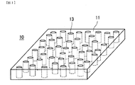
異方性光学フィルムとは、フィルムの膜厚方向に、フィルムのマトリックス領域とは屈折率の異なる領域が形成されたフィルムである。屈折率の異なる領域の形状は、特に制限されるものではないが、例えば、図1に示すように、マトリックス領域11に柱状又は棒状等に形成された屈折率の異なる柱状領域13が形成された異方性光学フィルム(以下、「ピラー構造の異方性光学フィルム」と称する場合がある。)10や、図2に示すように、マトリックス領域51に略板状に形成された屈折率の異なる板状領域53が形成された異方性光学フィルム(以下、「ルーバー構造の異方性光学フィルム」と称する場合がある。)50や、図示していないが、ピラー構造とルーバー構造が混在したハイブリッド型の異方性光学フィルム等がある。(Structure of anisotropic optical film)
An anisotropic optical film is a film in which a region having a refractive index different from the matrix region of the film is formed in the film thickness direction. The shape of the regions having different refractive indexes is not particularly limited. For example, as shown in FIG. 1,
(異方性光学フィルムの特性)
上述した構造を有する異方性光学フィルムは、当該フィルムへの入射光の入射角度により光拡散性(透過率)が異なる、すなわち入射角依存性を有する光拡散フィルムである。この異方性光学フィルムに所定の入射角で入射した光は、屈折率の異なる領域の配向方向(例えば、ピラー構造における柱状領域13の延在方向(配向方向)やルーバー構造における板状領域53の高さ方向)と略平行である場合には拡散が優先され、当該方向に平行でない場合には透過が優先される。(Characteristics of anisotropic optical film)
The anisotropic optical film having the above-described structure is a light diffusing film having different light diffusivity (transmittance) depending on an incident angle of incident light to the film, that is, having an incident angle dependency. Light incident on the anisotropic optical film at a predetermined incident angle is aligned in the orientation direction of regions having different refractive indexes (for example, the extending direction of
ここで、図3〜図7を参照しながら、異方性光学フィルムの光拡散性についてより具体的に説明する。ここでは、上述したピラー構造の異方性光学フィルムのうち、柱状領域13の配向方向Pがフィルムの膜厚方向(法線方向)と一致する異方性光学フィルム10と(図4を参照)、柱状領域23の配向方向Pがフィルムの膜厚方向(法線方向)と一致しない異方性光学フィルム20(図5を参照)の光拡散性を例に挙げて説明する。なお、異方性光学フィルム20の柱状領域23の配向方向Pは、フィルムの法線方向から約20°傾斜した方向となっている。
Here, the light diffusibility of the anisotropic optical film will be described more specifically with reference to FIGS. Here, among the anisotropic optical films having the pillar structure described above, the anisotropic
光拡散性の評価方法は、以下のようにして行った。まず、図3に示すように、異方性光学フィルム10、20を、光源1と検出器2との間に配置する。本形態においては、光源1からの照射光Iが、異方性光学フィルム10、20の法線方向から入射する場合を入射角0°とした。また、異方性光学フィルム10、20は直線Lを中心として、任意に回転させることができるように配置され、光源1及び検出器2は固定されている。
The evaluation method of light diffusibility was performed as follows. First, as shown in FIG. 3, the anisotropic
異方性光学フィルム10、20を、それぞれ、図4及び図5のA−A軸(異方性光学フィルムの径(辺)方向の軸)を図3に示す回転中心の直線Lに選んだ場合(回転方向A)と、B−B軸(A−A軸と直交する軸)を図3に示す回転中心の直線Lに選んだ場合(回転方向B)における光拡散性を評価した。回転方向Aと回転方向Bのそれぞれに配置した異方性光学フィルム10を回転させて得られた光拡散性の評価結果を図6に示した。同様に、回転方向Bに配置した異方性光学フィルム20を回転させて得られた光拡散性の評価結果を図7に示した。ここで、図6及び図7は、図3に示した方法で測定したものであり、縦軸を直線透過率(直線透過率=異方性光学フィルム10、20がある場合の検出器20の検出光量/異方性光学フィルム10、20がない場合の検出器20の検出光量)とし、横軸を異方性光学フィルム10、20への入射角とした。
The anisotropic
図6に示すように、柱状領域13の配向方向Pがフィルムの膜厚方向(法線方向)と一致する異方性光学フィルム10は、入射光の入射角によって直線透過率が変化するものである。また、異方性光学フィルム10について、A−A軸を直線Lに選んだ場合と、A−A軸に直交するB−B軸を直線Lに選んだ場合とで、ほとんど同じ光学プロファイルを示すものである。ここで、本明細書でいう光学プロファイルとは、図6や図7に示すように光拡散性の入射角依存性を示す曲線を意味する。光学プロファイルは、光拡散性を直接的に表現しているものではないが、直線透過率が低下することで逆に拡散透過率が増大していると解釈すれば、概ね光拡散性を示しているといえる。通常の等方的な光拡散フィルムでは、0°付近をピークとする山型の光学プロファイルを示すが、異方性光学フィルム10では、その配置方向(A−A軸方向及びB−B軸方向)に依存せずに、回転中心軸(直線Lとして選んだ軸)が変わってもほぼ同じ直線透過率を示し、法線方向(0°)で入射する場合の透過率と比較して、±5〜10°の入射角で一旦直線透過率が極小値になり、その入射角(の絶対値)が大きくなるにつれて直線透過率が大きくなり、±45〜60°の入射角で直線透過率が極大値となる谷型の光学プロファイルを示す。このように、異方性光学フィルム10は、入射光が法線方向(すなわち、柱状領域13の配向方向P)に近い±5〜10°の入射角範囲では強く拡散されるが、それ以上の入射角範囲では拡散が弱まり直線透過率が高まるという性質を有する。以下、最大直線透過率と最小直線透過率の差の1/2をなす角度範囲を拡散領域(拡散幅)と称し、それ以外の角度範囲を非拡散領域(透過領域)と称する。
As shown in FIG. 6, the anisotropic
また、図6に示す谷型の光学プロファイルは、入射角0°付近(特に、2つの極小値の間に存在する極大値付近)を軸にして対称になっており、本形態においては、これを散乱中心軸という。すなわち、散乱中心軸とは、入射角を変化させた際に光拡散性がその入射角を境に略対称性を有する光の入射角と一致する方向を意味する。ここで、略対称性を有するとするのは、散乱中心軸がフィルムの法線方向に対して傾きを有する場合には、光学プロファイルが厳密には対称性を有しないためである。異方性光学フィルム10においては、散乱中心軸と柱状領域13の配向方向Pとは平行となる。
Further, the valley-shaped optical profile shown in FIG. 6 is symmetric with respect to an incident angle of about 0 ° (particularly, the vicinity of the maximum value existing between two minimum values). Is called the scattering center axis. That is, the scattering central axis means a direction in which the light diffusibility coincides with the incident angle of light having substantially symmetry with respect to the incident angle when the incident angle is changed. Here, the reason why the optical profile is substantially symmetric is that the optical profile is not strictly symmetric when the scattering central axis is inclined with respect to the normal direction of the film. In the anisotropic
ここで、散乱中心軸と柱状領域の配向方向Pとが平行であるとは、屈折率の法則(Snellの法則)を満たすものであればよく、厳密に平行である必要はない。Snellの法則は、屈折率n1の媒質から屈折率n2の媒質の界面に対して光が入射する場合、その入射角θ1と屈折角θ2との間に、n1sinθ1=n2sinθ2の関係が成立するものである。例えば、n1=1(空気)、n2=1.51(異方性光学フィルム)とすると、散乱中心軸の傾き(入射角)が30°の場合、柱状領域の配向方向(屈折角)は約19°となるが、このように入射角と屈折角が異なっていてもSnellの法則を満たしていれば、本形態においては平行の概念に包含される。Here, the phrase “the scattering center axis and the alignment direction P of the columnar region are parallel” only needs to satisfy the law of refractive index (Snell's law), and does not need to be strictly parallel. Snell's law is that n 1 sin θ 1 = n between the incident angle θ 1 and the refraction angle θ 2 when light is incident on the interface of the refractive index n 2 from the medium having the refractive index n 1. The relationship of 2 sin θ 2 is established. For example, assuming that n 1 = 1 (air) and n 2 = 1.51 (anisotropic optical film), when the inclination (incident angle) of the scattering center axis is 30 °, the orientation direction (refractive angle) of the columnar region Is about 19 °, but if the angle of incidence and the angle of refraction are different, Snell's law is satisfied, and this embodiment is included in the concept of parallelism.
次に、図7に示すように、柱状領域13の配向方向Pがフィルムの膜厚方向(法線方向)と一致しない異方性光学フィルム20は、入射光の入射角によって直線透過率が変化するものである点では、異方性光学フィルム10と同様である。ただし、図示してはいないが、柱状領域13の配向方向Pがフィルムの法線方向と一致していないため、A−A軸を直線Lに選んだ場合と、A−A軸に直交するB−B軸を直線Lに選んだ場合とでは、異なる光学プロファイルを示す。また、異方性光学フィルム20は、入射角20°付近を中心として、入射角15°付近と30°付近に極小値を有する谷型の光学プロファイルを示す。このように、異方性光学フィルム20は、入射光が法線方向から20°傾いた方向(すなわち、柱状領域13の配向方向P)に近い入射角範囲(拡散領域)では強く拡散されるが、それ以上の入射角範囲(非拡散領域)では拡散が弱まり直線透過率が高まるという性質を有する。また、図7に示す谷型の光学プロファイルは、入射角20°付近(特に、2つの極小値の間に存在する極大値付近)を軸にして対称になっており、異方性光学フィルム20の散乱中心軸は約20°の方向といえ、柱状領域13の配向方向Pと平行となっている。
Next, as shown in FIG. 7, in the anisotropic
このように、ピラー構造を有する異方性光学フィルム(異方性光拡散層が単層のみの場合)では、散乱中心軸方向及びこれに近い入射角範囲(拡散領域)では強く拡散されるが、散乱中心軸方向から離れるほど直線透過率が高まるという性質を有している。 Thus, in an anisotropic optical film having a pillar structure (when the anisotropic light diffusion layer is only a single layer), although it is strongly diffused in the scattering central axis direction and an incident angle range (diffusion region) close thereto, As the distance from the central axis direction increases, the linear transmittance increases.
≪先行技術の課題とその解決手段の概要≫
次に、先行技術における異方性光学フィルムの課題とその解決手段の概要について説明する。≪Overview of prior art issues and solutions≫
Next, the problem of the anisotropic optical film in the prior art and the outline of the solution means will be described.
(先行技術の課題)
以上説明したようなピラー構造を有する異方性光拡散層を単層のみ有する異方性光学フィルムを液晶表示パネル等に用いた場合、散乱中心軸を適宜調整することで、視野角をある程度広げ、視野角方向における輝度及びコントラストを改善することができる。(Prior art issues)
When an anisotropic optical film having only a single anisotropic light diffusion layer having a pillar structure as described above is used for a liquid crystal display panel or the like, the viewing angle is widened to some extent by adjusting the scattering central axis appropriately. The brightness and contrast in the angular direction can be improved.
しかしながら、視野角方向における輝度及びコントラストを改善しようとして、ピラー構造を有する異方性光拡散層を単層のみ有する異方性光学フィルムを用いると、視野角方向以外の他の方向(例えば、表示パネルの法線方向)の輝度及びコントラストを大きく低下させてしまうという現象が生じてしまう。また、視野角を更に広げようとした場合には、視野角方向以外の他の方向の輝度及びコントラストの低下が著しいものとなってしまう。 However, when an anisotropic optical film having only a single layer of an anisotropic light diffusion layer having a pillar structure is used in order to improve luminance and contrast in the viewing angle direction, other directions other than the viewing angle direction (for example, the display panel) A phenomenon occurs in which the luminance and contrast in the normal direction are greatly reduced. Further, when the viewing angle is further increased, the brightness and contrast in directions other than the viewing angle direction are significantly reduced.
本発明者らが上記現象の原因を検討したところ、ピラー構造を有する異方性光拡散層を単層のみ有する異方性光学フィルムでは、輝度やコントラストを向上させようとして非拡散領域における直線透過率を向上させると、拡散領域が縮小してしまうため視野角が狭くなってしまい、一方、視野角を広げようとして拡散領域を拡大しようとすると、非拡散領域における直線透過率が低くなってしまうことが分かった。すなわち、本発明者らは、ピラー構造を有する異方性光拡散層を単層のみ有する異方性光学フィルムでは非拡散領域における直線透過率の向上と、拡散領域(拡散幅)の拡大を両立することが困難であるという課題を見出した。 When the present inventors examined the cause of the above phenomenon, an anisotropic optical film having only a single anisotropic light diffusing layer having a pillar structure has a linear transmittance in a non-diffusing region in order to improve luminance and contrast. If it is improved, the diffusion area will be reduced and the viewing angle will be narrowed. On the other hand, if the diffusion area is expanded to increase the viewing angle, the linear transmittance in the non-diffusing area may be reduced. I understood. That is, the inventors of the present invention can achieve both an improvement in linear transmittance in a non-diffusion region and an expansion of a diffusion region (diffusion width) in an anisotropic optical film having only a single layer of an anisotropic light diffusion layer having a pillar structure. I found a problem that is difficult.
(先行技術の課題解決手段の概要)
かかる課題を解決するためには、図8に太線で示すように、異方性光学フィルムが、非拡散領域における高い直線透過率を有するとともに、広い拡散領域(拡散幅)を有することが理想的であると考えられる。そこで、本発明者らは、このような非拡散領域における直線透過率の向上と拡散領域(拡散幅)の拡大を両立させた異方性光学フィルムを得るために更に検討を進めた。その結果、特許文献2に記載されているように、単に、各異方性光拡散層の散乱中心軸の方向を異ならせただけでは不十分であり、異なる直線透過率及び拡散強度を有する異方性光拡散層を2層以上積層し、且つ、各異方性光拡散層の最大直線透過率及び最小直線透過率(拡散強度)を特定の範囲内とすることで、非拡散領域における直線透過率の向上と拡散領域(拡散幅)の拡大を両立することが可能となることを知見した。(Overview of prior art problem solving means)
In order to solve such a problem, it is ideal that the anisotropic optical film has a high linear transmittance in the non-diffusion region and a wide diffusion region (diffusion width) as shown by a thick line in FIG. It is thought that. Therefore, the present inventors have further studied to obtain an anisotropic optical film that achieves both improvement in linear transmittance in such a non-diffusion region and expansion of the diffusion region (diffusion width). As a result, as described in Patent Document 2, it is not sufficient to simply change the direction of the scattering center axis of each anisotropic light diffusion layer, and anisotropic light diffusion having different linear transmittance and diffusion intensity. Two or more layers are stacked, and the maximum linear transmittance and the minimum linear transmittance (diffusion intensity) of each anisotropic light diffusion layer are within a specific range, thereby improving the linear transmittance and diffusing in the non-diffusing region. It has been found that it is possible to achieve both expansion of the region (diffusion width).
また、本発明者らは、拡散領域(拡散幅)を更に効果的に拡大するためには、散乱中心軸を特定の角度範囲ずらした異方性光拡散層を積層することが有効であることも併せて知見した。 In addition, the inventors of the present invention can effectively expand the diffusion region (diffusion width) by stacking an anisotropic light diffusion layer in which the scattering center axis is shifted by a specific angle range. I found out.
以上のように、特定範囲の直線透過率(最大直線透過率)及び拡散強度(最小直線透過率)を有し、且つ、これらの直線透過率及び拡散強度が互いに異なる異方性光拡散層を2層以上積層した異方性光学フィルムによれば、非拡散領域における直線透過率の向上と拡散領域(拡散幅)の拡大を両立すること可能となる。従って、このような異方性光学フィルムを液晶表示パネル等に用いることにより、視野角方向における表示特性(輝度及びコントラスト等)を改善しつつ、他の方向における表示特性の低下を抑制することができる。以下、これらの知見に基づいて成された本形態に係る異方性光学フィルムについて、詳細に説明する。 As described above, two anisotropic light diffusing layers having a linear transmittance (maximum linear transmittance) and diffusion intensity (minimum linear transmittance) in a specific range and different from each other in the linear transmittance and diffusion intensity are two layers. According to the laminated anisotropic optical films as described above, it is possible to achieve both the improvement of the linear transmittance in the non-diffusion region and the expansion of the diffusion region (diffusion width). Therefore, by using such an anisotropic optical film for a liquid crystal display panel or the like, it is possible to improve display characteristics (such as luminance and contrast) in the viewing angle direction and suppress deterioration in display characteristics in other directions. it can. Hereinafter, the anisotropic optical film according to the present embodiment made based on these findings will be described in detail.
≪本形態に係る異方性光学フィルムの構成≫
図9及び図10を参照しながら、本形態に係る異方性光学フィルム100の構成について説明する。図9は、本形態に係る異方性光学フィルム100の全体構成の一例を示す模式図である。図10は、本形態に係る異方性光学フィルム100における異方性光拡散層110、120の構成の一例を示す模式図であり、(a)が異方性光拡散層110の構成を、(b)が異方性光拡散層120の構成を示している。<< Configuration of anisotropic optical film according to this embodiment >>
The configuration of the anisotropic
<全体構成>
図9に示すように、異方性光学フィルム100は、2層の異方性光拡散層110、120が積層された異方性光学フィルムである。本発明に係る異方性光学フィルムは、異方性光拡散層として、少なくとも、相対的に入射光の透過率が高い異方性光拡散層(a)と、相対的に入射光の透過率が低い(拡散強度が強い)異方性光拡散層(b)とを有することが必要である。本形態に係る異方性光学フィルム100は、上記異方性光拡散層(a)として、上層側に積層された異方性光拡散層110を有し、上記異方性光拡散層(b)として、下層側に積層された異方性光拡散層120を有している。ただし、本発明では、異方性光拡散層(a)と異方性光拡散層(b)の積層順序は特に制限されず、本形態に係る異方性光拡散層110が下層側に、異方性光拡散層120が上層側に積層されていてもよい。なお、本形態では、異方性光拡散層が2層積層された構成を示しているが、本発明に係る異方性光学フィルムとしては、異方性光拡散層が3層以上積層されているものであってもよい。<Overall configuration>
As shown in FIG. 9, the anisotropic
また、各異方性光拡散層110、120の間には、透明性を有する粘着層130が更に積層されている。この粘着層130は、必要に応じて設ければよいが、後述する実施例に示すように、粘着層130を有する方が、異方性光学フィルム100の非拡散領域における透過率の最大値がやや大きくなり、拡散領域の幅(拡散幅)がやや広くなるため好適である。ここで、異方性光学フィルムが、3層以上の異方性光拡散層を有する場合には、全ての異方性光拡散層の間に粘着層があってもよいし、一部の異方性光拡散層の間のみに粘着層があってもよいし、全ての異方性光拡散層が粘着層無しに積層されていてもよい。
A transparent
<異方性光拡散層110、120>
異方性光学フィルム100を構成する各異方性光拡散層110、120は、上述した単層の異方性光学フィルム10、20等と同様の構成を有しており、入射光の入射角により直線透過率が変化する光拡散性を有している。また、図10に示すように、異方性光拡散層110、120は、それぞれ、光重合性化合物を含む組成物の硬化物からなり、マトリックス領域111、121と、当該マトリックス領域111、121とは屈折率の異なる複数の柱状領域113、123を有している。この柱状領域113、123の配向方向(延在方向)Pは、散乱中心軸と平行になるように形成されており、異方性光拡散層110、120が所望の透過率及び拡散性を有するように適宜定められている。このような構造は、詳しくは後述するが、例えば、光重合性化合物を含む組成物をシート状に設け、所望の散乱中心軸と平行な光線を光源からシートに対して照射し、組成物を硬化させることにより形成でき、光線を照射した部分が柱状領域113、123となり、光線を照射していない部分がマトリックス領域111、121となる。なお、「平行」の概念については上述した通り、Snellの法則を満たすものであれば本形態における「平行」の概念に含まれる。<Anisotropic light diffusion layers 110 and 120>
The anisotropic
(柱状領域)
また、本形態に係る柱状領域113、123は、マトリックス領域111、121中に、複数の柱状又は棒状の硬化領域として設けられており、各々の柱状領域113、123は、それぞれ配向方向Pが散乱中心軸と平行になるように形成されたものである。従って、同一の異方性光拡散層(例えば、異方性光拡散層110)における複数の柱状領域(例えば、柱状領域111)は、互いに平行となるように形成されている。また、柱状領域113、123の形状は、柱状又は棒状であれば、柱状領域113、123の配向方向Pに垂直な断面の形状は特に制限されるものではない。例えば、図10では柱状領域113、123の断面形状を円形状に示しているが、柱状領域113、123の断面形状は、円形状に限定されるものではなく、楕円形状、多角形状、不定形状等、特に限定されるものではない。ただし、異方性光学フィルム100の非拡散領域における直線透過率の向上と拡散領域(拡散幅)の拡大をより効果的に実現するためには、柱状領域113、123の断面における短径と長径のアスペクト比が、2未満であることが好ましく、1.5未満であることがより好ましい。(Columnar area)
In addition, the
(直線透過率)
異方性光拡散層110は、上述したように、相対的に透過率の高い層である異方性光拡散層(a)に相当する層である。ここで、直線透過率が最大となる入射角で異方性光拡散層110に入射した光の直線透過率を「最大直線透過率」と定義し、直線透過率が最小となる入射角で異方性光拡散層110に入射した光の直線透過率を「最小直線透過率」と定義すると、異方性光拡散層110は、最大直線透過率が40%以上95%未満であり、最小直線透過率が20%未満であることが必要である。(Linear transmittance)
As described above, the anisotropic
また、異方性光拡散層120は、上述したように、相対的に透過率の低い(拡散強度の強い)層である異方性光拡散層(b)に相当する層である。ここで、直線透過率が最大となる入射角で異方性光拡散層120に入射した光の直線透過率を「最大直線透過率」と定義し、直線透過率が最小となる入射角で異方性光拡散層120に入射した光の直線透過率を「最小直線透過率」と定義すると、異方性光拡散層120は、最大直線透過率が20%以上40%未満であり、最小直線透過率が20%未満であることが必要である。
Further, as described above, the anisotropic
異方性光拡散層110(透過率が相対的に高い異方性光拡散層(a)に相当)と異方性光拡散層120(拡散強度が相対的に強い異方性光拡散層(b)に相当)の最大直線透過率及び最小直線透過率を上記範囲とすることにより、異方性光学フィルム100において、非拡散領域における直線透過率の向上と拡散領域(拡散幅)の拡大を両立することが可能となる。換言すれば、異方性光拡散層110の最大直線透過率及び最小直線透過率、並びに、異方性光拡散層120の最大直線透過率及び最小直線透過率のいずれか一つでも、上記範囲から外れる場合には、非拡散領域における直線透過率の向上と拡散領域の幅(拡散幅)の拡大を両立させることはできない。上記最大直線透過率及び最小直線透過率の範囲を有する異方性光拡散層110と異方性光拡散層120が積層された異方性光学フィルム100を表示装置の拡散フィルムとして使用することで、視野角方向における表示特性(輝度及びコントラスト等)を改善しつつ、他の方向における表示特性の低下を抑制することができる。
Maximum straight line of anisotropic light diffusion layer 110 (corresponding to anisotropic light diffusion layer (a) having relatively high transmittance) and anisotropic light diffusion layer 120 (corresponding to anisotropic light diffusion layer (b) having relatively high diffusion intensity) By setting the transmittance and the minimum linear transmittance in the above ranges, in the anisotropic
非拡散領域における直線透過率を更に向上させ、拡散領域の幅(拡散幅)を更に拡大するためには、異方性光拡散層110(透過率が相対的に高い異方性光拡散層(a)に相当)の最大直線透過率が55%以上70%未満であり、且つ、最小直線透過率が15%以下であることが好ましく、また、異方性光拡散層120(拡散強度が相対的に強い異方性光拡散層(b)に相当)の最大直線透過率が30%以上40%未満であり、且つ、最小直線透過率が5%以下であることが好ましい。 In order to further improve the linear transmittance in the non-diffusion region and further expand the width (diffusion width) of the diffusion region, it corresponds to the anisotropic light diffusion layer 110 (an anisotropic light diffusion layer (a) having a relatively high transmittance). ) Is preferably 55% or more and less than 70%, and the minimum linear transmittance is preferably 15% or less, and the anisotropic light diffusion layer 120 (anisotropic light diffusion having a relatively high diffusion intensity) The maximum linear transmittance of the layer (b) is preferably 30% or more and less than 40%, and the minimum linear transmittance is preferably 5% or less.
ここで、異方性光拡散層110、120における最大直線透過率及び最小直線透過率は、製造時の設計パラメータによって調整することができる。パラメータの例としては、塗膜の組成、塗膜の膜厚、構造形成時に与える塗膜への温度等が挙げられる。塗膜の組成は構成成分を適宜選択し調合することで、最大直線透過率及び最小直線透過率は変化する。設計パラメータでは、膜厚が厚いほど最大直線透過率及び最小直線透過率は低くなりやすく、薄いほど高くなりやすい。温度が高いほど最大直線透過率及び最小直線透過率は低くなりやすく、低いほど高くなりやすい。これらのパラメータの組み合わせにより、最大直線透過率及び最小直線透過率のそれぞれを適宜調節することが可能である。 Here, the maximum linear transmittance and the minimum linear transmittance in the anisotropic light diffusion layers 110 and 120 can be adjusted by design parameters at the time of manufacture. Examples of the parameters include the composition of the coating film, the film thickness of the coating film, the temperature to the coating film given during structure formation, and the like. The composition of the coating film changes the maximum linear transmittance and the minimum linear transmittance by appropriately selecting and preparing the constituent components. In the design parameter, the maximum linear transmittance and the minimum linear transmittance tend to be lower as the film thickness is thicker, and higher as the film thickness is thinner. The maximum linear transmittance and the minimum linear transmittance tend to be lower as the temperature is higher, and higher as the temperature is lower. Each of the maximum linear transmittance and the minimum linear transmittance can be appropriately adjusted by a combination of these parameters.
(散乱中心軸)
次に、図11を参照しながら、異方性光拡散層110、120における散乱中心軸Qについて説明する。図11は、異方性光拡散層110、120における散乱中心軸Qを説明するための3次元極座標表示である。(Scattering center axis)
Next, the scattering center axis Q in the anisotropic light diffusion layers 110 and 120 will be described with reference to FIG. FIG. 11 is a three-dimensional polar coordinate display for explaining the scattering center axis Q in the anisotropic light diffusion layers 110 and 120.
異方性光拡散層110、120の各々は、少なくとも1つの散乱中心軸を有するが、この散乱中心軸は、上述したように、異方性光拡散層110、120への入射角を変化させた際に光拡散性がその入射角を境に略対称性を有する光の入射角と一致する方向を意味する。なお、このときの入射角は、異方性光拡散層110、120の光学プロファイルを測定し、この光学プロファイルにおける極小値に挟まれた略中央部(拡散領域の中央部)となる。 Each of the anisotropic light diffusion layers 110 and 120 has at least one scattering center axis. As described above, this scattering center axis is a light beam when the incident angle to the anisotropic light diffusion layers 110 and 120 is changed. It means a direction in which diffusivity coincides with an incident angle of light having substantially symmetry with respect to the incident angle. Note that the incident angle at this time is approximately the central portion (the central portion of the diffusion region) sandwiched between the minimum values in the optical profiles obtained by measuring the optical profiles of the anisotropic light diffusion layers 110 and 120.
また、上記散乱中心軸は、図11に示すような3次元極座標表示によれば、異方性光拡散層110、120の表面をxy平面とし、法線をz軸とすると、極角θと方位角φとによって表現することができる。つまり、図11中のPxyが、上記異方性光拡散層110、120の表面に投影した散乱中心軸の長さ方向ということができる。Further, according to the three-dimensional polar coordinate display as shown in FIG. 11, the scattering central axis is defined as polar angle θ and azimuth when the surfaces of anisotropic light diffusion layers 110 and 120 are the xy plane and the normal is the z axis. It can be expressed by φ. That is, it can be said that P xy in FIG. 11 is the length direction of the scattering central axis projected on the surfaces of the anisotropic light diffusion layers 110 and 120.
ここで、異方性光拡散層110、120の法線(図11に示すz軸)と散乱中心軸Qとのなす極角θ(−90°<θ<90°)を本形態における散乱中心軸角度と定義すると、異方性光拡散層110(透過率が相対的に高い異方性光拡散層(a)に相当)の散乱中心軸角度と、異方性光拡散層120(拡散強度が相対的に強い異方性光拡散層(b)に相当)の散乱中心軸角度との差の絶対値が、0°以上30°以下であることが好ましい。散乱中心軸角度の差の絶対値を上記範囲とすることで、異方性光学フィルム100の非拡散領域における直線透過率を低下させることなく、拡散領域の幅を更に拡大することが可能となる。この効果をより効果的に実現するためには、異方性光拡散層110の散乱中心軸角度と異方性光拡散層120の散乱中心軸角度との差の絶対値が0°以上20°以下であることがより好ましい。なお、異方性光拡散層110、120の散乱中心軸角度は、これらを製造する際に、シート状の光重合性化合物を含む組成物に照射する光線の方向を変えることで、所望の角度に調整することができる。なお、散乱中心軸角度の正負は、異方性光拡散層110、120の面方向における所定の対称軸(例えば、図4及び図5におけるB−B軸)と、異方性光拡散層110、120の法線の両方を通る平面に対して、散乱中心軸が一側に傾斜している場合を+、他側に傾斜している場合を−と定義することとする。例えば、異方性光拡散層110、120を図5のB−B軸を回転中心として回転させた場合、図7における入射角度の+、−と、散乱中心軸角度の+、−とは一致することとなる。
Here, the polar angle θ (−90 ° <θ <90 °) formed by the normal line (z-axis shown in FIG. 11) of the anisotropic light diffusion layers 110 and 120 and the scattering center axis Q is the scattering center axis angle in this embodiment. If defined, the scattering center axis angle of the anisotropic light diffusion layer 110 (corresponding to the anisotropic light diffusion layer (a) having a relatively high transmittance) and the anisotropic light diffusion layer 120 (anisotropic light diffusion having a relatively high diffusion intensity) The absolute value of the difference from the scattering center axis angle of the layer (b) is preferably from 0 ° to 30 °. By setting the absolute value of the difference in scattering center axis angle within the above range, the width of the diffusion region can be further expanded without reducing the linear transmittance in the non-diffusion region of the anisotropic
また、上記散乱中心軸角度(極角)の差の絶対値が上記範囲を満たすことに加えて、異方性光拡散層110の散乱中心軸の方位角と異方性光拡散層120の散乱中心軸の方位角との差の絶対値が0°以上20°以下であることが好ましい。これにより、異方性光学フィルム100の非拡散領域における直線透過率を低下させることなく、拡散領域の幅を更に拡大することが可能となる。
Further, in addition to the absolute value of the difference between the scattering center axis angles (polar angles) satisfying the above range, the azimuth angle of the scattering center axis of the anisotropic
ここで、異方性光拡散層110、120の各々は、単一層中に、傾きの異なる柱状領域群(同一の傾きを有する柱状領域の集合)を複数有していてもよい。このように、単一層中に傾きの異なる柱状領域群が複数ある場合には、各柱状領域の群の傾きに対応して散乱中心軸も複数となる。散乱中心軸が複数ある場合には、これら複数の散乱中心軸のうちの少なくとも1つの散乱中心軸が、上述した散乱中心軸角度の条件を満たしていればよい。例えば、異方性光拡散層110が2つの散乱中心軸Q1、Q2を有し、異方性光拡散層120が2つの散乱中心軸Q3、Q4を有している場合、Q1とQ2の少なくともいずれか一方の散乱中心軸角度と、Q3とQ4の少なくともいずれか一方の散乱中心軸角度との差の絶対値が0°以上30°以下であることが好ましく、0°以上20°以下であることがより好ましい。
Here, each of the anisotropic light diffusion layers 110 and 120 may include a plurality of columnar region groups having different inclinations (a set of columnar regions having the same inclination) in a single layer. Thus, when there are a plurality of columnar region groups having different inclinations in a single layer, there are also a plurality of scattering central axes corresponding to the inclination of each group of columnar regions. When there are a plurality of scattering center axes, it is only necessary that at least one of the plurality of scattering center axes satisfies the above-described condition of the scattering center axis angle. For example, when the anisotropic
また、各異方性光拡散層110、120の散乱中心軸Qの極角θ(すなわち、散乱中心軸角度)が±10〜60°であることが好ましく、±30〜45°であることがより好ましい。散乱中心軸角度が−10°より大きく+10°未満では、液晶表示パネルを含む表示パネルの視野角方向におけるコントラストや輝度を十分に向上させることができない。一方、散乱中心軸角度が+60°より大きい、もしくは、−60°未満である場合、製造過程においてシート状に設けられた光重合性化合物を含む組成物に対して深い傾きから光を照射する必要があり、照射光の吸収効率が悪く製造上不利であるため好ましくない。 Further, the polar angle θ (that is, the scattering center axis angle) of the scattering center axis Q of each of the anisotropic light diffusion layers 110 and 120 is preferably ± 10 to 60 °, and more preferably ± 30 to 45 °. . When the scattering center axis angle is greater than −10 ° and less than + 10 °, the contrast and brightness in the viewing angle direction of the display panel including the liquid crystal display panel cannot be sufficiently improved. On the other hand, when the scattering center axis angle is greater than + 60 ° or less than −60 °, it is necessary to irradiate the composition containing the photopolymerizable compound provided in the form of a sheet from a deep inclination in the production process. This is not preferable because the absorption efficiency of irradiation light is poor and the manufacturing is disadvantageous.
(屈折率)
異方性光拡散層110、120は、光重合性化合物を含む組成物を硬化したものであるが、この組成物としては、次のような組み合わせが使用可能である。
(1)後述する単独の光重合性化合物を使用するもの
(2)後述する複数の光重合性化合物を混合使用するもの
(3)単独又は複数の光重合性化合物と、光重合性を有しない高分子化合物とを混合して使用するもの(Refractive index)
The anisotropic light diffusion layers 110 and 120 are obtained by curing a composition containing a photopolymerizable compound. As the composition, the following combinations can be used.
(1) Those using a single photopolymerizable compound to be described later (2) Those using a plurality of photopolymerizable compounds to be described later (3) Single or a plurality of photopolymerizable compounds and no photopolymerizability Used by mixing with polymer compounds
上記いずれの組み合わせにおいても、光照射により異方性光拡散層110、120中に、屈折率の異なるミクロンオーダーの微細な構造が形成されると推察されており、これにより、本形態に示される特異な異方性光拡散特性が発現されるものと思われる。従って、上記(1)では、光重合の前後における屈折率変化が大きい方が好ましく、また、(2)、(3)では屈折率の異なる複数の材料を組み合わせることが好ましい。なお、ここでの屈折率変化や屈折率の差とは、具体的には、0.01以上、好ましくは0.05以上、より好ましくは0.10以上の変化や差を示すものである。 In any of the above combinations, it is presumed that a micron-order fine structure with a different refractive index is formed in the anisotropic light diffusion layers 110 and 120 by light irradiation. It is thought that anisotropic light diffusion characteristics are exhibited. Therefore, in the above (1), it is preferable that the refractive index change is large before and after the photopolymerization. In (2) and (3), it is preferable to combine a plurality of materials having different refractive indexes. Here, the refractive index change and the refractive index difference specifically indicate a change or difference of 0.01 or more, preferably 0.05 or more, more preferably 0.10 or more.
(各層の厚み)
異方性光拡散層110、120の各々の厚みは、15μm以上100μm以下であることが好ましい。厚みを上記範囲とすることで、異方性光学フィルム100の非拡散領域における直線透過率の向上と拡散領域(拡散幅)の拡大をより効果的に実現することができる。なお、異方性光学フィルムが異方性光拡散層を3層以上有する場合には、各々の異方性光拡散層の厚みが、15μm以上100μm以下であることが好ましい。(Thickness of each layer)
The thickness of each of the anisotropic light diffusion layers 110 and 120 is preferably 15 μm or more and 100 μm or less. By making thickness into the said range, the improvement of the linear transmittance | permeability in the non-diffusion area | region of the anisotropic
<異方性光学フィルムの他の形態>
本形態に係る異方性光学フィルム100は、光重合性化合物を含む組成物の硬化物からなる異方性光拡散層を複数(本形態では、異方性光拡散層110、120)積層されたものであるが、この積層体を透光性基体上に積層したり、この積層体の両側に透光性基体を積層したりしてもよい。ここで、透光性基体としては、透明性が高いもの程良好であり、全光線透過率(JIS K7361−1)が80%以上、より好ましくは85%以上、最も好ましくは90%以上のものが好適に使用でき、また、ヘイズ値(JIS K7136)が3.0以下、より好ましくは1.0以下、最も好ましくは0.5以下のものが好適に使用できる。具体的には、透光性基体としては、透明なプラスチックフィルムやガラス板等が使用可能であるが、薄く、軽く、割れ難く、生産性に優れる点でプラスチックフィルムが好適である。具体例としては、ポリエチレンテレフタレート(PET)、ポリエチレンナフタレート(PEN)、トリアセチルセルロース(TAC)、ポリカーボネート(PC)、ポリエーテルスルホン(PES)、セロファン、ポリエチレン(PE)、ポリプロピレン(PP)、ポリビニルアルコール(PVA)、シクロオレフィン樹脂等が挙げられ、これらを単独で又は混合して、更には積層したものを用いることができる。また、透光性基体の厚みは、用途や生産性を考慮すると、1μm〜5mmであることが好ましく、10〜500μmであることがより好ましく、50〜150μmであることが更に好ましい。<Other forms of anisotropic optical film>
The anisotropic
≪本形態に係る異方性光学フィルムの製造方法≫
以上、本形態に係る異方性光学フィルム100の構成について詳細に説明したが、続いて、かかる構成を有する異方性光学フィルム100の製造方法について説明する。≪Method for manufacturing anisotropic optical film according to this embodiment≫
As mentioned above, although the structure of the anisotropic
本形態に係る異方性光学フィルム100は、異方性光拡散層110、120を直接又は粘着層130を介して積層することで得られるが、各異方性光拡散層110、120は、特定の光硬化性樹脂層に特殊な条件でUV等の光線を照射することにより製造することができる。以下、初めに異方性光拡散層110、120の原料を説明し、次いで製造プロセスを説明する。
The anisotropic
<異方性光拡散層の原料>
異方性光拡散層110、120の原料については、(1)光重合性化合物、(2)光開始剤、(3)配合量、その他任意成分の順に説明する。<Raw material for anisotropic light diffusion layer>
The raw materials of the anisotropic light diffusion layers 110 and 120 will be described in the order of (1) photopolymerizable compound, (2) photoinitiator, (3) blending amount, and other optional components.
(光重合性化合物)
本形態に係る異方性光拡散層110、120を形成する材料である光重合性化合物は、ラジカル重合性又はカチオン重合性の官能基を有するポリマー、オリゴマー、モノマーから選択される光重合性化合物と光開始剤とから構成され、紫外線及び/又は可視光線を照射することにより重合・硬化する材料である。(Photopolymerizable compound)
The photopolymerizable compound which is a material for forming the anisotropic light diffusion layers 110 and 120 according to the present embodiment includes a photopolymerizable compound selected from a polymer, an oligomer, and a monomer having a radical polymerizable or cationic polymerizable functional group, and light. It is a material composed of an initiator and polymerized and cured by irradiation with ultraviolet rays and / or visible rays.
ラジカル重合性化合物は、主に分子中に1個以上の不飽和二重結合を含有するもので、具体的には、エポキシアクリレート、ウレタンアクリレート、ポリエステルアクリレート、ポリエーテルアクリレート、ポリブタジエンアクリレート、シリコーンアクリレート等の名称で呼ばれるアクリルオリゴマーと、2−エチルヘキシルアクリレート、イソアミルアクリレート、ブトキシエチルアクリレート、エトキシジエチレングリコールアクリレート、フェノキシエチルアクリレート、テトラヒドロフルフリルアクリレート、イソノルボルニルアクリレート、2−ヒドロキシエチルアクリレート、2−ヒドロキシプロピルアクリレート、2−アクリロイロキシフタル酸、ジシクロペンテニルアクリレート、トリエチレングリコールジアクリレート、ネオペンチルグリコールジアクリレート、1,6−ヘキサンジオールジアクリレート、ビスフェノールAのEO付加物ジアクリレート、トリメチロールプロパントリアクリレート、EO変成トリメチロールプロパントリアクリレート、ペンタエリスリトールトリアクリレート、ペンタエリスリトールテトラアクリレート、ジトリメチロールプロパンテトラアクリレート、ジペンタエリスリトールヘキサアクリレート等のアクリレートモノマーが挙げられる。また、これらの化合物は、各単体で用いてもよく、複数混合して用いてもよい。なお、同様にメタクリレートも使用可能であるが、一般にはメタクリレートよりもアクリレートの方が光重合速度が速いので好ましい。 The radically polymerizable compound mainly contains one or more unsaturated double bonds in the molecule, specifically, epoxy acrylate, urethane acrylate, polyester acrylate, polyether acrylate, polybutadiene acrylate, silicone acrylate, etc. Acrylic oligomer called by the name of 2-ethylhexyl acrylate, isoamyl acrylate, butoxyethyl acrylate, ethoxydiethylene glycol acrylate, phenoxyethyl acrylate, tetrahydrofurfuryl acrylate, isonorbornyl acrylate, 2-hydroxyethyl acrylate, 2-hydroxypropyl acrylate 2-acryloyloxyphthalic acid, dicyclopentenyl acrylate, triethylene glycol diacrylate Neopentyl glycol diacrylate, 1,6-hexanediol diacrylate, EO adduct diacrylate of bisphenol A, trimethylolpropane triacrylate, EO modified trimethylolpropane triacrylate, pentaerythritol triacrylate, pentaerythritol tetraacrylate, ditrimethylol Examples thereof include acrylate monomers such as propanetetraacrylate and dipentaerythritol hexaacrylate. These compounds may be used alone or in combination. Similarly, methacrylate can also be used, but acrylate is generally preferable to methacrylate because of its higher photopolymerization rate.
カチオン重合性化合物としては、分子中にエポキシ基やビニルエーテル基、オキセタン基を1個以上有する化合物が使用できる。エポキシ基を有する化合物としては、2−エチルヘキシルジグリコールグリシジルエーテル、ビフェニルのグリシジルエーテル、ビスフェノールA、水添ビスフェノールA、ビスフェノールF、ビスフェノールAD、ビスフェノールS、テトラメチルビスフェノールA、テトラメチルビスフェノールF、テトラクロロビスフェノールA、テトラブロモビスフェノールA等のビスフェノール類のジグリシジルエーテル類、フェノールノボラック、クレゾールノボラック、ブロム化フェノールノボラック、オルトクレゾールノボラック等のノボラック樹脂のポリグリシジルエーテル類、エチレングリコール、ポリエチレングリコール、ポリプロピレングリコール、ブタンジオール、1,6−ヘキサンジオール、ネオペンチルグリコール、トリメチロールプロパン、1,4−シクロヘキサンジメタノール、ビスフェノールAのEO付加物、ビスフェノールAのPO付加物等のアルキレングリコール類のジグリシジルエーテル類、ヘキサヒドロフタル酸のグリシジルエステルやダイマー酸のジグリシジルエステル等のグリシジルエステル類が挙げられる。 As the cationically polymerizable compound, a compound having at least one epoxy group, vinyl ether group or oxetane group in the molecule can be used. The compounds having an epoxy group include 2-ethylhexyl diglycol glycidyl ether, glycidyl ether of biphenyl, bisphenol A, hydrogenated bisphenol A, bisphenol F, bisphenol AD, bisphenol S, tetramethylbisphenol A, tetramethylbisphenol F, tetrachloro Diglycidyl ethers of bisphenols such as bisphenol A and tetrabromobisphenol A, polyglycidyl ethers of novolac resins such as phenol novolak, cresol novolak, brominated phenol novolak, orthocresol novolak, ethylene glycol, polyethylene glycol, polypropylene glycol, Butanediol, 1,6-hexanediol, neopentyl glycol, trimethyl Diglycidyl ethers of alkylene glycols such as propane adduct of 1,4-cyclohexanedimethanol, bisphenol A, PO adduct of bisphenol A, glycidyl ester of hexahydrophthalic acid, diglycidyl ester of dimer acid, etc. Examples thereof include glycidyl esters.
エポキシ基を有する化合物としては更に、3,4−エポキシシクロヘキシルメチル−3’,4’−エポキシシクロヘキサンカルボキシレート、2−(3,4−エポキシシクロヘキシル−5,5−スピロ−3,4−エポキシ)シクロヘキサン−メタ−ジオキサン、ジ(3,4−エポキシシクロヘキシルメチル)アジペート、ジ(3,4−エポキシ−6−メチルシクロヘキシルメチル)アジペート、3,4−エポキシ−6−メチルシクロヘキシル−3’,4’−エポキシ−6’−メチルシクロヘキサンカルボキシレート、メチレンビス(3,4−エポキシシクロヘキサン)、ジシクロペンタジエンジエポキシド、エチレングリコールのジ(3,4−エポキシシクロヘキシルメチル)エーテル、エチレンビス(3,4−エポキシシクロヘキサンカルボキシレート)、ラクトン変性3,4−エポキシシクロヘキシルメチル−3’,4’−エポキシシクロヘキサンカルボキシレート、テトラ(3,4−エポキシシクロヘキシルメチル)ブタンテトラカルボキシレート、ジ(3,4−エポキシシクロヘキシルメチル)−4,5−エポキシテトラヒドロフタレート等の脂環式エポキシ化合物も挙げられるが、これらに限定されるものではない。 Further, as the compound having an epoxy group, 3,4-epoxycyclohexylmethyl-3 ′, 4′-epoxycyclohexanecarboxylate, 2- (3,4-epoxycyclohexyl-5,5-spiro-3,4-epoxy) Cyclohexane-meta-dioxane, di (3,4-epoxycyclohexylmethyl) adipate, di (3,4-epoxy-6-methylcyclohexylmethyl) adipate, 3,4-epoxy-6-methylcyclohexyl-3 ′, 4 ′ -Epoxy-6'-methylcyclohexanecarboxylate, methylene bis (3,4-epoxycyclohexane), dicyclopentadiene diepoxide, di (3,4-epoxycyclohexylmethyl) ether of ethylene glycol, ethylene bis (3,4-epoxy Cyclohexane cal Xylate), lactone-modified 3,4-epoxycyclohexylmethyl-3 ′, 4′-epoxycyclohexanecarboxylate, tetra (3,4-epoxycyclohexylmethyl) butanetetracarboxylate, di (3,4-epoxycyclohexylmethyl)- Examples thereof include, but are not limited to, alicyclic epoxy compounds such as 4,5-epoxytetrahydrophthalate.
ビニルエーテル基を有する化合物としては、例えば、ジエチレングリコールジビニルエーテル、トリエチレングリコールジビニルエーテル、ブタンジオールジビニルエーテル、ヘキサンジオールジビニルエーテル、シクロヘキサンジメタノールジビニルエーテル、ヒドロキシブチルビニルエーテル、エチルビニルエーテル、ドデシルビニルエーテル、トリメチロールプロパントリビニルエーテル、プロペニルエーテルプロピレンカーボネート等が挙げられるが、これらに限定されるものではない。なお、ビニルエーテル化合物は、一般にはカチオン重合性であるが、アクリレートと組み合わせることによりラジカル重合も可能である。 Examples of the compound having a vinyl ether group include diethylene glycol divinyl ether, triethylene glycol divinyl ether, butanediol divinyl ether, hexanediol divinyl ether, cyclohexanedimethanol divinyl ether, hydroxybutyl vinyl ether, ethyl vinyl ether, dodecyl vinyl ether, trimethylol propane tri Vinyl ether, propenyl ether propylene carbonate and the like can be mentioned, but are not limited thereto. Vinyl ether compounds are generally cationically polymerizable, but radical polymerization is also possible by combining with acrylates.
また、オキセタン基を有する化合物としては、1,4−ビス[(3−エチル−3−オキセタニルメトキシ)メチル]ベンゼン、3−エチル−3−(ヒドロキシメチル)−オキセタン等が使用できる。 As the compound having an oxetane group, 1,4-bis [(3-ethyl-3-oxetanylmethoxy) methyl] benzene, 3-ethyl-3- (hydroxymethyl) -oxetane and the like can be used.
なお、以上のカチオン重合性化合物は、各単体で用いてもよく、複数混合して用いてもよい。上記光重合性化合物は、上述に限定されるものではない。また、十分な屈折率差を生じさせるべく、上記光重合性化合物には、低屈折率化を図るために、フッ素原子(F)を導入しても良く、高屈折率化を図るために、硫黄原子(S)、臭素原子(Br)、各種金属原子を導入しても良い。さらに、特表2005−514487号公報に開示されるように、酸化チタン(TiO2)、酸化ジルコニウム(ZrO2)、酸化錫(SnOx)等の高屈折率の金属酸化物からなる超微粒子の表面に、アクリル基やメタクリル基、エポキシ基等の光重合性官能基を導入した機能性超微粒子を上述の光重合性化合物に添加することも有効である。The above cationic polymerizable compounds may be used alone or in combination. The photopolymerizable compound is not limited to the above. Further, in order to cause a sufficient difference in refractive index, fluorine atoms (F) may be introduced into the photopolymerizable compound in order to reduce the refractive index, and in order to increase the refractive index, Sulfur atoms (S), bromine atoms (Br), and various metal atoms may be introduced. Further, as disclosed in JP 2005-514487 A, ultrafine particles made of a metal oxide having a high refractive index such as titanium oxide (TiO 2 ), zirconium oxide (ZrO 2 ), tin oxide (SnO x ), etc. It is also effective to add functional ultrafine particles having a photopolymerizable functional group such as an acryl group, a methacryl group, and an epoxy group introduced to the surface to the photopolymerizable compound.
(光開始剤)
ラジカル重合性化合物を重合させることのできる光開始剤としては、ベンゾフェノン、ベンジル、ミヒラーズケトン、2−クロロチオキサントン、2,4−ジエチルチオキサントン、ベンゾインエチルエーテル、ベンゾインイソプロピルエーテル、ベンゾインイソブチルエーテル、2,2−ジエトキシアセトフェノン、ベンジルジメチルケタール、2,2−ジメトキシ−1,2−ジフェニルエタン−1−オン、2−ヒドロキシ−2−メチル−1−フェニルプロパン−1−オン、1−ヒドロキシシクロヘキシルフェニルケトン、2−メチル−1−[4−(メチルチオ)フェニル]−2−モルフォリノプロパノン−1、1−[4−(2−ヒドロキシエトキシ)−フェニル]−2−ヒドロキシ−2−メチル−1−プロパン−1−オン、ビス(シクロペンタジエニル)−ビス(2,6−ジフルオロ−3−(ピル−1−イル)チタニウム、2−ベンジル−2−ジメチルアミノ−1−(4−モルフォリノフェニル)−ブタノン−1、2,4,6−トリメチルベンゾイルジフェニルフォスフィンオキサイド等が挙げられる。また、これらの化合物は、各単体で用いてもよく、複数混合して用いてもよい。(Photoinitiator)
Photoinitiators that can polymerize radically polymerizable compounds include benzophenone, benzyl, Michler's ketone, 2-chlorothioxanthone, 2,4-diethylthioxanthone, benzoin ethyl ether, benzoin isopropyl ether, benzoin isobutyl ether, 2,2- Diethoxyacetophenone, benzyldimethyl ketal, 2,2-dimethoxy-1,2-diphenylethane-1-one, 2-hydroxy-2-methyl-1-phenylpropan-1-one, 1-hydroxycyclohexyl phenyl ketone, 2 -Methyl-1- [4- (methylthio) phenyl] -2-morpholinopropanone-1, 1- [4- (2-hydroxyethoxy) -phenyl] -2-hydroxy-2-methyl-1-propane-1 -One, bis (cyclo Ntadienyl) -bis (2,6-difluoro-3- (pyr-1-yl) titanium, 2-benzyl-2-dimethylamino-1- (4-morpholinophenyl) -butanone-1,2,4,6 -Trimethyl benzoyl diphenyl phosphine oxide etc. Moreover, these compounds may be used individually or may be used in mixture of two or more.
また、カチオン重合性化合物の光開始剤は、光照射によって酸を発生し、この発生した酸により上述のカチオン重合性化合物を重合させることができる化合物であり、一般的には、オニウム塩、メタロセン錯体が好適に用いられる。オニウム塩としては、ジアゾニウム塩、スルホニウム塩、ヨードニウム塩、ホスホニウム塩、セレニウム塩等が使用され、これらの対イオンには、BF4 −、PF6 −、AsF6 −、SbF6 −等のアニオンが用いられる。具体例としては、4−クロロベンゼンジアゾニウムヘキサフルオロホスフェート、トリフェニルスルホニウムヘキサフルオロアンチモネート、トリフェニルスルホニウムヘキサフルオロホスフェート、(4−フェニルチオフェニル)ジフェニルスルホニウムヘキサフルオロアンチモネート、(4−フェニルチオフェニル)ジフェニルスルホニウムヘキサフルオロホスフェート、ビス[4−(ジフェニルスルホニオ)フェニル]スルフィド−ビス−ヘキサフルオロアンチモネート、ビス[4−(ジフェニルスルホニオ)フェニル]スルフィド−ビス−ヘキサフルオロホスフェート、(4−メトキシフェニル)ジフェニルスルホニウムヘキサフルオロアンチモネート、(4−メトキシフェニル)フェニルヨードニウムヘキサフルオロアンチモネート、ビス(4−t−ブチルフェニル)ヨードニウムヘキサフルオロホスフェート、ベンジルトリフェニルホスホニウムヘキサフルオロアンチモネート、トリフェニルセレニウムヘキサフルオロホスフェート、(η5−イソプロピルベンゼン)(η5−シクロペンタジエニル)鉄(II)ヘキサフルオロホスフェート等が挙げられるが、これらに限定されるものではない。また、これらの化合物は、各単体で用いてもよく、複数混合して用いてもよい。The photoinitiator of the cationic polymerizable compound is a compound capable of generating an acid by light irradiation and polymerizing the above cationic polymerizable compound with the generated acid. Generally, an onium salt, a metallocene is used. Complexes are preferably used. As the onium salt, a diazonium salt, a sulfonium salt, an iodonium salt, a phosphonium salt, a selenium salt, or the like is used, and these counter ions include anions such as BF 4 − , PF 6 − , AsF 6 − , SbF 6 − and the like. Used. Specific examples include 4-chlorobenzenediazonium hexafluorophosphate, triphenylsulfonium hexafluoroantimonate, triphenylsulfonium hexafluorophosphate, (4-phenylthiophenyl) diphenylsulfonium hexafluoroantimonate, (4-phenylthiophenyl) diphenyl. Sulfonium hexafluorophosphate, bis [4- (diphenylsulfonio) phenyl] sulfide-bis-hexafluoroantimonate, bis [4- (diphenylsulfonio) phenyl] sulfide-bis-hexafluorophosphate, (4-methoxyphenyl) Diphenylsulfonium hexafluoroantimonate, (4-methoxyphenyl) phenyliodonium hexafluoroantimonate Bis (4-t-butylphenyl) iodonium hexafluorophosphate, benzyltriphenylphosphonium hexafluoroantimonate, triphenyl selenium hexafluorophosphate, (η5-isopropylbenzene) (η5-cyclopentadienyl) iron (II) hexa Although fluorophosphate etc. are mentioned, it is not limited to these. These compounds may be used alone or in combination.
(配合量、その他任意成分)
本形態において、上記光開始剤は、光重合性化合物100重量部に対して、0.01〜10重量部、好ましくは0.1〜7重量部、より好ましくは0.1〜5重量部程度配合される。これは、0.01重量部未満では光硬化性が低下し、10重量部を超えて配合した場合には、表面だけが硬化して内部の硬化性が低下してしまう弊害、着色、柱状構造の形成の阻害を招くからである。これらの光開始剤は、通常粉体を光重合性化合物中に直接溶解して使用されるが、溶解性が悪い場合は光開始剤を予め極少量の溶剤に高濃度に溶解させたものを使用することもできる。このような溶剤としては光重合性であることが更に好ましく、具体的には炭酸プロピレン、γ−ブチロラクトン等が挙げられる。また、光重合性を向上させるために公知の各種染料や増感剤を添加することも可能である。さらに、光重合性化合物を加熱により硬化させることのできる熱硬化開始剤を光開始剤と共に併用することもできる。この場合、光硬化の後に加熱することにより光重合性化合物の重合硬化を更に促進し完全なものにすることが期待できる。(Blend amount, other optional ingredients)
In this embodiment, the photoinitiator is 0.01 to 10 parts by weight, preferably 0.1 to 7 parts by weight, more preferably about 0.1 to 5 parts by weight with respect to 100 parts by weight of the photopolymerizable compound. Blended. This is because when less than 0.01 parts by weight, the photo-curing property is lowered, and when blending more than 10 parts by weight, only the surface is cured and the internal curability is lowered, coloring, columnar structure This is because it inhibits the formation of. These photoinitiators are usually used by directly dissolving powder in a photopolymerizable compound, but if the solubility is poor, a photoinitiator dissolved beforehand in a very small amount of solvent at a high concentration is used. It can also be used. Such a solvent is more preferably photopolymerizable, and specific examples thereof include propylene carbonate and γ-butyrolactone. It is also possible to add various known dyes and sensitizers in order to improve the photopolymerizability. Furthermore, the thermosetting initiator which can harden a photopolymerizable compound by heating can also be used together with a photoinitiator. In this case, by heating after photocuring, it can be expected to further accelerate the polymerization and curing of the photopolymerizable compound to complete it.
本形態では、上記の光重合性化合物を単独で、又は複数を混合した組成物を硬化させて、異方性光拡散層110、120を形成することができる。また、光重合性化合物と光硬化性を有しない高分子樹脂の混合物を硬化させることによっても本形態の異方性光拡散層110、120を形成することができる。ここで使用できる高分子樹脂としては、アクリル樹脂、スチレン樹脂、スチレン−アクリル共重合体、ポリウレタン樹脂、ポリエステル樹脂、エポキシ樹脂、セルロース系樹脂、酢酸ビニル系樹脂、塩化ビニル−酢酸ビニル共重合体、ポリビニルブチラール樹脂等が挙げられる。これらの高分子樹脂と光重合性化合物は、光硬化前は十分な相溶性を有していることが必要であるが、この相溶性を確保するために各種有機溶剤や可塑剤等を使用することも可能である。なお、光重合性化合物としてアクリレートを使用する場合は、高分子樹脂としてはアクリル樹脂から選択することが相溶性の点で好ましい。
In this embodiment, the anisotropic
また、光重合性化合物を含む組成物を調製する際の溶剤としては、例えば、酢酸エチル、酢酸ブチル、アセトン、メチルエチルケトン、メチルイソブチルケトン、シクロヘキサノン、トルエン、キシレン等を使用することができる。 Moreover, as a solvent at the time of preparing the composition containing a photopolymerizable compound, ethyl acetate, butyl acetate, acetone, methyl ethyl ketone, methyl isobutyl ketone, cyclohexanone, toluene, xylene, etc. can be used, for example.
<製造プロセス>
次に、本形態の異方性光拡散層110、120の製造方法(プロセス)について説明する。まず、上述の光重合性化合物を含む組成物(以下、「光硬化性組成物」と称する場合がある。)を透明PETフィルムのような適当な基体上に塗布し又はシート状に設け、成膜して光硬化性樹脂層を設ける。この光硬化性樹脂層を、必要に応じて乾燥し溶剤を揮発させた上で、光硬化性樹脂層上に光を照射することで、異方性光拡散層110、120を作製することができる。<Manufacturing process>
Next, a manufacturing method (process) of the anisotropic light diffusion layers 110 and 120 of this embodiment will be described. First, a composition containing the above-mentioned photopolymerizable compound (hereinafter sometimes referred to as “photocurable composition”) is applied on a suitable substrate such as a transparent PET film or provided in the form of a sheet. A photocurable resin layer is provided as a film. The anisotropic light diffusion layers 110 and 120 can be produced by irradiating the photocurable resin layer with light after drying the photocurable resin layer and volatilizing the solvent as necessary.
(光重合性化合物を含む組成物を基体上にシート状に設ける手法)
ここで、光重合性化合物を含む組成物を基体上にシート状に設ける手法としては、通常の塗工方式や印刷方式が適用される。具体的には、エアドクターコーティング、バーコーティング、ブレードコーティング、ナイフコーティング、リバースコーティング、トランスファロールコーティング、グラビアロールコーティング、キスコーティング、キャストコーティング、スプレーコーティング、スロットオリフィスコーティング、カレンダーコーティング、ダムコーティング、ディップコーティング、ダイコーティング等のコーティングや、グラビア印刷等の凹版印刷、スクリーン印刷等の孔版印刷等の印刷等が使用できる。組成物が低粘度の場合は、基体の周囲に一定の高さの堰を設けて、この堰で囲まれた中に組成物をキャストすることもできる。(Method of providing a composition containing a photopolymerizable compound in a sheet form on a substrate)
Here, as a method of providing the composition containing the photopolymerizable compound in a sheet form on the substrate, a normal coating method or printing method is applied. Specifically, air doctor coating, bar coating, blade coating, knife coating, reverse coating, transfer roll coating, gravure roll coating, kiss coating, cast coating, spray coating, slot orifice coating, calendar coating, dam coating, dip coating Coating such as die coating, intaglio printing such as gravure printing, printing such as stencil printing such as screen printing, and the like can be used. When the composition has a low viscosity, a weir having a certain height can be provided around the substrate, and the composition can be cast in the area surrounded by the weir.
(マスクの積層)
本形態に係る異方性光拡散層110、120の特徴である柱状領域113、123を効率良く形成させるために、光硬化性組成物層の光照射側に密着して光の照射強度を局所的に変化させるマスクを積層することも可能である。マスクの材質としては、カーボン等の光吸収性のフィラーをポリマーマトリックス中に分散したもので、入射光の一部はカーボンに吸収されるが、開口部は光が十分に透過できるような構成のものが好ましい。また、通常の透明フィルムを光硬化性組成物層上に積層するだけでも、酸素障害を防ぎ柱状領域113、123の形成を促す上で有効である。このようなマスクや透明フィルムを介した光照射では、光重合性化合物を含む組成物中に、その照射強度に応じた光重合反応を生じるため、屈折率分布を生じ易く、本形態に係る異方性光拡散層110、120の作製に有効である。(Stacking of masks)
In order to efficiently form the
(光源)
光重合性化合物を含む組成物(光硬化性樹脂層)に光照射を行うための光源としては、通常はショートアークの紫外線発生光源が使用され、具体的には高圧水銀灯、低圧水銀灯、メタハライドランプ、キセノンランプ等が使用可能である。また、光硬化性樹脂層上には、所望の散乱中心軸Qと平行な光線を照射する必要があるが、このような平行光を得るためには、点光源を配置して、この点光源と光硬化性樹脂層の間に平行光を照射するためのフレネルレンズ等の光学レンズを配置して、光硬化性樹脂層に平行光を照射することで、異方性光拡散層110、120を作製することができる。一方、線状光源を使用する場合は、特開2005−292219号公報に記載されているように、線状光源とシート状の光重合性化合物を含む組成物との間に、筒状物の集合を介在させ、この筒状物を通して光照射を行うことにより、異方性光拡散層110、120を作製することができる。線状光源を使用すると連続生産を行うことができるため好ましい。線状光源としては、ケミカルランプ(紫外線を出す蛍光灯)を使用することができる。ケミカルランプは、直径20〜50mm、発光長100〜1500mm程度のものが市販されており、作成する異方性光拡散層110、120の大きさに合わせて適宜選択することができる。(light source)
As a light source for irradiating a composition (photocurable resin layer) containing a photopolymerizable compound, a short arc ultraviolet light source is usually used. Specifically, a high pressure mercury lamp, a low pressure mercury lamp, or a metahalide is used. A lamp, a xenon lamp, or the like can be used. In addition, it is necessary to irradiate a light beam parallel to the desired scattering center axis Q on the photocurable resin layer. In order to obtain such parallel light, a point light source is disposed, and this point light source An anisotropic
光重合性化合物を含む組成物に照射する光線は、該光重合性化合物を硬化可能な波長を含んでいることが必要で、通常は水銀灯の365nmを中心とする波長の光が利用される。この波長帯を使って異方性光拡散層110、120を作製する場合、照度としては0.01〜100mW/cm2の範囲であることが好ましく、より好ましくは0.1〜20mW/cm2の範囲である。照度が0.01mW/cm2未満であると硬化に長時間を要するため、生産効率が悪くなり、100mW/cm2を超えると光重合性化合物の硬化が速すぎて構造形成を生じず、目的の異方性拡散特性を発現できなくなるからである。なお、光の照射時間は特に限定されないが、10〜180秒間、より好ましくは30〜120秒間である。The light beam applied to the composition containing the photopolymerizable compound needs to have a wavelength capable of curing the photopolymerizable compound, and usually a light having a wavelength centered at 365 nm of a mercury lamp is used. When fabricating the anisotropic light-diffusing
本形態の異方性光拡散層110、120は、上述の如く低照度の光を比較的長時間照射することにより光硬化性組成物層中に特定の内部構造が形成されることで得られるものである。そのため、このような光照射だけでは未反応のモノマー成分が残存して、べたつきを生じたりしてハンドリング性や耐久性に問題がある場合がある。そのような場合は、1000mW/cm2以上の高照度の光を追加照射して残存モノマーを重合させることができる。このときの光照射はマスクを積層した側の逆側から行うのが好ましい。The anisotropic
以上のようにして作製した異方性光拡散層110、120を直接又は粘着層130を介して積層することで、本形態に係る異方性光学フィルム100を得ることができる。
The anisotropic
上記粘着層130に用いられる粘着剤としては、透明性を有するものであれば特に制限されるものではないが、常温で感圧接着性を有する粘着剤が好適に使用される。このような粘着剤としては、例えば、ポリエステル系樹脂、エポキシ系樹脂、ポリウレタン系樹脂、シリコーン系樹脂、アクリル系樹脂等の樹脂を挙げることができる。特に、アクリル系樹脂は光学的透明性が高いこと、比較的安価なこと等から好ましい。粘着層を介して複数の光拡散層(本形態では、光拡散層110、120)を積層する場合、粘着層の厚みは5〜50μm程度であることが好ましい。
The pressure-sensitive adhesive used for the pressure-
一方、異方性光拡散層110に異方性光拡散層120を直接積層する場合には、異方性光拡散層110用の光硬化性樹脂層を硬化させた後に、当該硬化後の異方性光拡散層110上に直接光重合性化合物を含む組成物を塗布するか又はシート状に設ければよい。さらに、異方性光拡散層110と同様にして異方性光拡散層120を作製することで、本形態に係る異方性光学フィルム100を得ることができる。
On the other hand, when the anisotropic
≪本形態に係る異方性光学フィルムの用途≫
以上、本形態に係る異方性光学フィルム100の構成及び製造方法について詳細に説明したが、続いて、図12及び図13を参照しながら、上述した異方性光学フィルム100の好適用途について説明する。図12及び図13は、本形態に係る異方性光学フィルム100を用いた液晶表示パネルの構成の一例を示す模式図である。≪Use of anisotropic optical film according to this embodiment≫
As mentioned above, although the structure and manufacturing method of the anisotropic
本形態に係る異方性光学フィルム100は、表示装置用の拡散フィルムとして好適に使用することができる。異方性光学フィルム100を好適に利用可能な表示装置としては、表示性能に視野角依存性を有するものであればよい。このような表示装置としては、例えば、液晶表示パネル、PDPパネル、有機ELパネル、フィールドエミッションディスプレイ、リアプロジェクター等を挙げることができる。ここで、表示性能に視野角依存性を有するとは、正面方向(表示装置の観察面の法線方向、視野角0°方向)から観察した場合と斜め方向(視野角0°より大きい方向)から観察した場合とで、コントラスト、階調特性、色度等の表示性能が異なることや、輝度が大きく変化することを意味する。特に、液晶表示パネルのTNモードやSTNモードでこのような視野角依存性が強く現れるが、これらの表示装置の観察面側に、本形態の異方性光学フィルム100を設けることにより、視野角方向において優れた表示特性(輝度やコントラスト等)を持ちながら、他の方向における表示特性の低下を抑制することができる。
The anisotropic
また、例えば、本形態に係る異方性光学フィルム100を液晶表示装置(LCD)に用いる場合には、液晶表示パネルの出射光側に、異方性光学フィルム100を配置すればよい。具体的には、図12及び図13に示すように、透明電極が形成された一対の透明ガラス基板1011、1012の間に、ネマチック液晶1013が挟持され、このガラス基板1011、1012の両側に、一対の偏光板1014、1015が設けられた液晶表示パネルにおいて、偏光板1014上、又は、ガラス基板1011と偏光板1014との間に、本形態に係る異方性光学フィルム100を配置することができる。なお、上記の透明ガラス基板、ネマチック液晶、偏光板等としては、一般に公知のものを使用することができる。
Further, for example, when the anisotropic
次に、本発明を実施例及び比較例により、更に具体的に説明するが、本発明は、これらの例によって何ら限定されるものではない。 Next, although an example and a comparative example explain the present invention still more concretely, the present invention is not limited at all by these examples.
以下の方法に従って、本発明の異方性光学フィルム及び比較例の異方性光学フィルムを製造した。 According to the following method, the anisotropic optical film of the present invention and the anisotropic optical film of the comparative example were produced.
[実施例1]
厚さ100μmのPETフィルム(東洋紡社製、商品名:A4300)の縁部全周に、ディスペンサーを使い硬化性樹脂で高さ0.07mmの隔壁を形成した。この中に下記の光硬化性樹脂組成物を充填し、別のPETフィルムでカバーした。
・シリコーン・ウレタン・アクリレート(屈折率:1.460、重量平均分子量:5,890) 20重量部
(RAHN社製、商品名:00−225/TM18)
・ネオペンチルグリコールジアクリレート(屈折率:1.450) 30重量部
(ダイセルサイテック社製、商品名Ebecryl145)
・ビスフェノールAのEO付加物ジアクリレート(屈折率:1.536) 15重量部
(ダイセルサイテック社製、商品名:Ebecyl150)
・フェノキシエチルアクリレート(屈折率:1.518) 40重量部
(共栄社化学製、商品名:ライトアクリレートPO−A)
・2,2−ジメトキシ−1,2−ジフェニルエタン−1−オン 4重量部
(BASF社製、商品名:Irgacure651)[Example 1]
A partition wall having a height of 0.07 mm was formed on the entire periphery of the edge of a PET film having a thickness of 100 μm (trade name: A4300, manufactured by Toyobo Co., Ltd.) using a dispenser. This was filled with the following photocurable resin composition and covered with another PET film.
Silicone urethane acrylate (refractive index: 1.460, weight average molecular weight: 5,890) 20 parts by weight (trade name: 00-225 / TM18, manufactured by RAHN)
・ Neopentyl glycol diacrylate (refractive index: 1.450) 30 parts by weight (manufactured by Daicel Cytec, trade name Ebecryl 145)
Bisphenol A EO adduct diacrylate (refractive index: 1.536) 15 parts by weight (manufactured by Daicel Cytec, trade name: Ebecyl 150)
・ Phenoxyethyl acrylate (refractive index: 1.518) 40 parts by weight (manufactured by Kyoeisha Chemical Co., Ltd., trade name: light acrylate PO-A)
・ 2,2-dimethoxy-1,2-diphenylethane-1-one 4 parts by weight (manufactured by BASF, trade name: Irgacure 651)
この両面をPETフィルムで挟まれた0.07mmの厚さの液膜を加熱して、上部からUVスポット光源(浜松ホトニクス社製、商品名:L2859−01)の落射用照射ユニットから出射される平行UV光線を塗膜面の法線方向から垂直に、照射強度5mW/cm2として1分間照射して、柱状構造を多数有する異方性光拡散層をPETフィルム上に形成した。A liquid film having a thickness of 0.07 mm sandwiched between PET films is heated and emitted from an upper part of an irradiation unit for epi-illumination of a UV spot light source (product name: L2859-01, manufactured by Hamamatsu Photonics). Parallel UV light was irradiated perpendicularly from the normal direction of the coating surface at an irradiation intensity of 5 mW / cm 2 for 1 minute to form an anisotropic light diffusion layer having many columnar structures on the PET film.
さらに、隔壁の高さを変更して0.03mmの隔壁を用いて、柱状構造を多数有する異方性光拡散層をPETフィルム上に形成した。 Furthermore, the anisotropic light-diffusion layer which has many columnar structures was formed on PET film using the 0.03 mm partition by changing the height of a partition.
PETフィルムを剥離した上で、それぞれの異方性光拡散層の単独の直線透過率を測定した結果を表1に示した。さらに、2つの異方性光拡散層を25μmの厚みの透明性粘着材を介して積層し、得られた異方性光学フィルムの直線透過率を測定した結果を表2に示した。 Table 1 shows the results of measuring the single linear transmittance of each anisotropic light diffusion layer after peeling the PET film. Further, Table 2 shows the results of measuring the linear transmittance of the anisotropic optical film obtained by laminating two anisotropic light diffusion layers through a transparent adhesive material having a thickness of 25 μm.
[実施例2]
平行UV光線の照射角度を変更することで、1層目の異方性光拡散層を約20°、2層目の異方性光拡散層を約5°である以外は実施例1と同様に2つの異方性光拡散層を得た。それぞれの光学特性と粘着を介して作成した異方性光学フィルムの光学特性を表1と表2に示した。[Example 2]
By changing the irradiation angle of the parallel UV light, the two different anisotropic light diffusion layers were about 20 °, and the second anisotropic light diffusion layer was about 5 °. An isotropic light diffusion layer was obtained. Tables 1 and 2 show the optical characteristics of the anisotropic optical films prepared through the respective optical characteristics and adhesion.
[実施例3]
平行UV光線の照射角度を変更することで、1層目の異方性光拡散層を約40°、2層目の異方性光拡散層を約20°である以外は実施例1と同様に2つの異方性光拡散層を得た。それぞれの光学特性と粘着を介して作成した異方性光学フィルムの光学特性を表1と表2に示した。[Example 3]
By changing the irradiation angle of the parallel UV light, two different differences were made as in Example 1, except that the first anisotropic light diffusion layer was about 40 ° and the second anisotropic light diffusion layer was about 20 °. An isotropic light diffusion layer was obtained. Tables 1 and 2 show the optical characteristics of the anisotropic optical films prepared through the respective optical characteristics and adhesion.
[実施例4]
実施例3と同一の異方性光拡散層の積層体を粘着材を介さずに作成した。1層目の異方性光拡散層を得た後、カバーのPETフィルムを剥離した後、0.03mmの隔壁を1層目に形成した隔壁の更に上に追加して形成し、1層目の異方性光拡散層の上に同様の光硬化性樹脂組成物を充填しPETフィルムでカバーをした。その後は同様の操作で、2層目の異方性光拡散層を形成し、1層目と2層目が密着した異方性光学フィルムを得た。それぞれの異方性光拡散層の光学特性は測定していないが、実施例3と同条件で作成されたそれぞれの異方性光拡散層の光学特性は、実施例3と同等であると推測される。得られた異方性光学フィルムの光学特性を表1と表2に示した。[Example 4]
The same laminate of anisotropic light diffusion layers as in Example 3 was prepared without using an adhesive material. After obtaining the first anisotropic light diffusing layer, the PET film of the cover is peeled off, and then a 0.03 mm barrier rib is additionally formed on the first barrier rib. A similar photocurable resin composition was filled on the isotropic light diffusion layer and covered with a PET film. Thereafter, in the same manner, a second anisotropic light diffusion layer was formed to obtain an anisotropic optical film in which the first and second layers were in close contact. Although the optical characteristics of each anisotropic light diffusion layer were not measured, it is estimated that the optical characteristics of each anisotropic light diffusion layer prepared under the same conditions as in Example 3 were the same as those in Example 3. The optical properties of the obtained anisotropic optical film are shown in Tables 1 and 2.
[実施例5]
平行UV光線の照射角度を変更することで、1層目の異方性光拡散層を約20°、2層目の異方性光拡散層を約10°とし、2層目の隔壁の高さを0.02mmとした以外は実施例1と同様に2つの異方性光拡散層を得た。それぞれの光学特性と粘着を介して作成した異方性光学フィルムの光学特性を表1と表2に示した。[Example 5]
By changing the irradiation angle of the parallel UV light, the first anisotropic light diffusion layer is about 20 °, the second anisotropic light diffusion layer is about 10 °, and the height of the second partition wall is 0.00. Two anisotropic light diffusion layers were obtained in the same manner as in Example 1 except that the thickness was 02 mm. Tables 1 and 2 show the optical characteristics of the anisotropic optical films prepared through the respective optical characteristics and adhesion.
[実施例6]
平行UV光線の照射角度を変更することで、1層目の異方性光拡散層を約20°、2層目の異方性光拡散層を約15°とし、1層目の隔壁の高さを0.10mm、2層目の隔壁の高さを0.03mmとした以外は実施例1と同様に2つの異方性光拡散層を得た。それぞれの光学特性と粘着を介して作成した異方性光学フィルムの光学特性を表1と表2に示した。[Example 6]
By changing the irradiation angle of the parallel UV light, the first anisotropic light diffusion layer is about 20 °, the second anisotropic light diffusion layer is about 15 °, and the height of the first partition wall is 0. Two anisotropic light diffusing layers were obtained in the same manner as in Example 1 except that the height of the partition walls of 10 mm and the second layer was 0.03 mm. Tables 1 and 2 show the optical characteristics of the anisotropic optical films prepared through the respective optical characteristics and adhesion.
[実施例7]
平行UV光線の照射角度を変更することで、1層目の異方性光拡散層を約20°、2層目の異方性光拡散層を約15°とした以外は実施例1と同様に2つの異方性光拡散層を得た。それぞれの光学特性と粘着を介して作成した異方性光学フィルムの光学特性を表1と表2に示した。[Example 7]
By changing the irradiation angle of the parallel UV light, the difference between the first and second anisotropic light diffusion layers was about 20 °, and the second anisotropic light diffusion layer was about 15 °. An isotropic light diffusion layer was obtained. Tables 1 and 2 show the optical characteristics of the anisotropic optical films prepared through the respective optical characteristics and adhesion.
[実施例8]
平行UV光線の照射角度を変更することで、1層目の異方性光拡散層を約15°、2層目の異方性光拡散層を約20°とし、1層目の隔壁の高さを0.03mm、2層目の隔壁の高さを0.07mmとした以外は実施例1と同様に2つの異方性光拡散層を得た。それぞれの光学特性と粘着を介して作成した異方性光学フィルムの光学特性を表1と表2に示した。[Example 8]
By changing the irradiation angle of the parallel UV light, the first anisotropic light diffusion layer is about 15 °, the second anisotropic light diffusion layer is about 20 °, and the height of the first partition wall is 0. Two anisotropic light diffusing layers were obtained in the same manner as in Example 1 except that 03 mm and the height of the second partition wall were 0.07 mm. Tables 1 and 2 show the optical characteristics of the anisotropic optical films prepared through the respective optical characteristics and adhesion.
[実施例9]
平行UV光線の照射角度を変更することで、1層目の異方性光拡散層を約0°、2層目の異方性光拡散層を約10°とし、1層目の隔壁の高さを0.05mm、2層目の隔壁の高さを0.03mmとした以外は実施例1と同様に2つの異方性光拡散層を得た。それぞれの光学特性と粘着を介して作成した異方性光学フィルムの光学特性を表1と表2に示した。[Example 9]
By changing the irradiation angle of the parallel UV light, the first anisotropic light diffusion layer is set to about 0 °, the second anisotropic light diffusion layer is set to about 10 °, and the height of the first partition wall is set to 0. Two anisotropic light diffusing layers were obtained in the same manner as in Example 1 except that the height of the partition wall of 05 mm and the second layer was 0.03 mm. Tables 1 and 2 show the optical characteristics of the anisotropic optical films prepared through the respective optical characteristics and adhesion.
[参考例1]
平行UV光線の照射角度を変更することで、1層目の異方性光拡散層を約30°、2層目の異方性光拡散層を約40°とし、1層目の隔壁の高さを0.07mm、2層目の隔壁の高さを0.03mmとした以外は実施例1と同様に2つの異方性光拡散層を得た。それぞれの光学特性と粘着を介して作成した異方性光学フィルムの光学特性を表1と表2に示した。
[ Reference Example 1]
By changing the irradiation angle of the parallel UV light, the first anisotropic light diffusion layer is about 30 °, the second anisotropic light diffusion layer is about 40 °, and the height of the first partition wall is 0. Two anisotropic light diffusion layers were obtained in the same manner as in Example 1 except that the height of the second partition wall was set to 0.03 mm. Tables 1 and 2 show the optical characteristics of the anisotropic optical films prepared through the respective optical characteristics and adhesion.
[比較例1]
実施例1の隔壁を0.1mmに変更した以外は同様にして異方性光拡散層を得た。1つの異方性光拡散層を作成したのみで、異方性光拡散層を積層した異方性光学フィルムは得なかった。得られた異方性光拡散層の光学特性を表1と表2に示した。[Comparative Example 1]
An anisotropic light diffusion layer was obtained in the same manner except that the partition wall of Example 1 was changed to 0.1 mm. Only one anisotropic light diffusion layer was prepared, and an anisotropic optical film having an anisotropic light diffusion layer laminated thereon was not obtained. The optical properties of the obtained anisotropic light diffusion layer are shown in Tables 1 and 2.
[比較例2]
2つの異方性光拡散層を同じ厚みで形成するために、隔壁の高さをそれぞれ0.07mmにする以外は実施例1と同様にして、それぞれの異方性光拡散層を得て、光学特性を測定し結果を表1に示した。実施例1と同様に粘着材を介して2つの異方性光拡散層を積層し、得られた異方性光学フィルムの光学特性を表2に示した。[Comparative Example 2]
In order to form two anisotropic light diffusing layers with the same thickness, each anisotropic light diffusing layer was obtained and optical characteristics were measured in the same manner as in Example 1 except that the height of the partition wall was 0.07 mm. The results are shown in Table 1. In the same manner as in Example 1, two anisotropic light diffusion layers were laminated through an adhesive material, and the optical characteristics of the obtained anisotropic optical film are shown in Table 2.
[比較例3]
2つの異方性光拡散層を同じ厚みで形成するために、隔壁の高さをそれぞれ0.03mmにする以外は実施例1と同様にして、それぞれの異方性光拡散層を得て、光学特性を測定し結果を表1に示した。実施例1と同様に粘着材を介して2つの異方性光拡散層を積層し、得られた異方性光学フィルムの光学特性を表2に示した。[Comparative Example 3]
In order to form two anisotropic light diffusion layers with the same thickness, each anisotropic light diffusion layer was obtained and optical characteristics were measured in the same manner as in Example 1 except that the height of the partition wall was 0.03 mm. The results are shown in Table 1. In the same manner as in Example 1, two anisotropic light diffusion layers were laminated through an adhesive material, and the optical characteristics of the obtained anisotropic optical film are shown in Table 2.
[比較例4]
2つの異方性光拡散層を同じ厚みで形成するために、隔壁の高さをそれぞれ0.07mmにする以外は実施例2と同様にして、それぞれの異方性光拡散層を得て、光学特性を測定し結果を表1に示した。実施例2と同様に粘着材を介して2つの異方性光拡散層を積層し、得られた異方性光学フィルムの光学特性を表2に示した。[Comparative Example 4]
In order to form the two anisotropic light diffusing layers with the same thickness, each anisotropic light diffusing layer was obtained and optical characteristics were measured in the same manner as in Example 2 except that the height of the partition wall was 0.07 mm. The results are shown in Table 1. In the same manner as in Example 2, two anisotropic light diffusion layers were laminated via an adhesive material, and the optical properties of the obtained anisotropic optical film are shown in Table 2.
[比較例5]
2つの異方性光拡散層を同じ厚みで形成するために、隔壁の高さをそれぞれ0.03mmにする以外は実施例2と同様にして、それぞれの異方性光拡散層を得て、光学特性を測定し結果を表1に示した。実施例2と同様に粘着材を介して2つの異方性光拡散層を積層し、得られた異方性光学フィルムの光学特性を表2に示した。[Comparative Example 5]
In order to form the two anisotropic light diffusing layers with the same thickness, each anisotropic light diffusing layer was obtained and optical characteristics were measured in the same manner as in Example 2 except that the height of the partition wall was 0.03 mm. The results are shown in Table 1. In the same manner as in Example 2, two anisotropic light diffusion layers were laminated via an adhesive material, and the optical properties of the obtained anisotropic optical film are shown in Table 2.

なお、上記表2における評価基準は以下の通りである。
◎ 透過率の最大値35%以上、且つ、拡散幅55°以上
○○ 透過率の最大値25%以上35%未満、且つ拡散幅55°以上
○ 透過率の最大値25%以上35%未満、且つ拡散幅40°以上55°未満
△ 透過率の最大値10%以上25%未満、且つ拡散幅40°以上55°未満
× 透過率の最大値10%以上25%未満、且つ拡散幅40°未満The evaluation criteria in Table 2 are as follows.
◎ Maximum transmittance 35% or more and diffusion width 55 ° or more ○○
表2に示すとおり、実施例の異方性光学フィルムは比較的高い透過率の最大値を有しながら、広い拡散幅を有していた。特に、実施例7および8は高い透過率と広い拡散幅を共に高いレベルでバランスしており、優れた異方性光学フィルムであるといえる。一方で、比較例の異方性光拡散層または異方性光学フィルムは、透過率は実施例と同等であったが拡散幅が狭いものであった。加えて、実施例3および4は、散乱軸方向が30〜40°付近にあり、かつ拡散幅が広いため、この方向での視野角改善に良好であり、実際の透過型LCDの表面に貼合して目視で確認したところ、輝度及びコントラストが良好で視野角が広くなり、色変化などの違和感も少ない表示体であった。
As shown in Table 2, the anisotropic optical films of the examples had a wide diffusion width while having a relatively high transmittance maximum. In particular, Examples 7 and 8 balance high transmittance and wide diffusion width at a high level, and can be said to be excellent anisotropic optical films. On the other hand, the anisotropic light diffusion layer or the anisotropic optical film of the comparative example had a transmittance that was the same as that of the example, but the diffusion width was narrow. In addition, since Examples 3 and 4 have a scattering axis direction in the vicinity of 30 to 40 ° and a wide diffusion width, they are excellent in improving the viewing angle in this direction, and are applied to the surface of an actual transmissive LCD. As a result of visual inspection, it was a display body with good brightness and contrast, a wide viewing angle, and less discomfort such as color change.
したがって、実施例の異方性光学フィルムは、高い透過率と拡散幅の両立ができ、表示体の拡散フィルムとして用いたときは、視野角に対して優れた特性を得ながら、正面方向のコントラストや輝度を低下させにくいなどの効果を得ることができる。 Therefore, the anisotropic optical films of the examples can achieve both high transmittance and diffusion width, and when used as a diffusion film for a display body, the contrast in the front direction is obtained while obtaining excellent characteristics with respect to the viewing angle. And the effect that it is difficult to reduce the luminance can be obtained.
以上、図面を参照しながら本発明の好適な実施の形態について説明したが、本発明は上述した形態に限定されない。すなわち、特許請求の範囲に記載された発明の範囲内で当業者が想到し得る他の形態または各種の変更例についても本発明の技術的範囲に属するものと理解される。 The preferred embodiment of the present invention has been described above with reference to the drawings, but the present invention is not limited to the above-described embodiment. That is, it is understood that other forms or various modifications that can be conceived by those skilled in the art within the scope of the invention described in the claims belong to the technical scope of the present invention.
例えば、上述した形態においては、異方性光拡散層を2層有する異方性光学フィルムについて説明したが、本発明に係る異方性光学フィルムは、異方性光拡散層を3層以上有するものであってもよい。 For example, in the embodiment described above, an anisotropic optical film having two anisotropic light diffusing layers has been described, but the anisotropic optical film according to the present invention has three or more anisotropic light diffusing layers. Also good.
100 異方性光学フィルム
110 異方性光拡散層(a)
111 マトリックス領域
113 柱状領域
120 異方性光拡散層(b)
121 マトリックス領域
123 柱状領域
130 粘着層
P 柱状領域の配向方向
100
121
Claims (4)
前記異方性光拡散層の各々は、マトリックス領域と、当該マトリックス領域とは屈折率の異なる複数の柱状領域とを有するものであり、
前記異方性光拡散層として、少なくとも、直線透過率が異なる2種類の異方性光拡散層(a)及び異方性光拡散層(b)を有し、
前記異方性光拡散層(a)は、直線透過率が最大となる入射角で入射した光の直線透過率である最大直線透過率が40%以上95%未満であり、且つ、直線透過率が最小となる入射角で入射した光の直線透過率である最小直線透過率が20%未満であり、
前記異方性光拡散層(b)は、前記最大直線透過率が20%以上40%未満であり、且つ、前記最小直線透過率が20%未満であり、
前記異方性光拡散層の各々は、少なくとも1つの散乱中心軸を有し、
前記異方性光拡散層の法線と前記散乱中心軸とのなす極角θ(−90°<θ<90°)を散乱中心軸角度とすると、
前記異方性光拡散層(a)の散乱中心軸角度と前記異方性光拡散層(b)の散乱中心軸角度の差の絶対値が、0°以上30°以下であることを特徴とする、異方性光学フィルム。 An anisotropic optical film in which two or more anisotropic light diffusion layers whose linear transmittance changes depending on the incident angle of incident light are laminated,
Each of the anisotropic light diffusion layers has a matrix region and a plurality of columnar regions having different refractive indexes from the matrix region.
The anisotropic light diffusion layer has at least two types of anisotropic light diffusion layers (a) and anisotropic light diffusion layers (b) having different linear transmittances,
The anisotropic light diffusion layer (a) has a maximum linear transmittance of 40% or more and less than 95%, which is a linear transmittance of light incident at an incident angle at which the linear transmittance is maximum, and has a minimum linear transmittance. The minimum linear transmittance, which is the linear transmittance of light incident at an incident angle of less than 20%,
The anisotropic light-diffusing layer (b), the maximum linear transmittance is less than 20% or more 40%, and, Ri said minimum linear transmittance is less than 20% der,
Each of the anisotropic light diffusing layers has at least one scattering central axis;
When a polar angle θ (−90 ° <θ <90 °) formed by a normal line of the anisotropic light diffusion layer and the scattering center axis is a scattering center axis angle,
Absolute value of the difference between the scattering center axis angle of the scattering center axis angle and the anisotropic light-diffusing layer of the anisotropic light-diffusing layer (a) (b), characterized in der Rukoto 0 ° or 30 ° or less, different Isotropic optical film.
Wherein the plurality of the anisotropic light-diffusing layers, and further comprising an adhesive layer having transparency, anisotropic optical film according to any one of claims 1-3.
Applications Claiming Priority (3)
| Application Number | Priority Date | Filing Date | Title |
|---|---|---|---|
| JP2014008815 | 2014-01-21 | ||
| JP2014008815 | 2014-01-21 | ||
| PCT/JP2015/051138 WO2015111523A1 (en) | 2014-01-21 | 2015-01-16 | Anisotropic optical film |
Publications (2)
| Publication Number | Publication Date |
|---|---|
| JPWO2015111523A1 JPWO2015111523A1 (en) | 2017-03-23 |
| JP6483030B2 true JP6483030B2 (en) | 2019-03-13 |
Family
ID=53681327
Family Applications (1)
| Application Number | Title | Priority Date | Filing Date |
|---|---|---|---|
| JP2015558828A Active JP6483030B2 (en) | 2014-01-21 | 2015-01-16 | Anisotropic optical film |
Country Status (6)
| Country | Link |
|---|---|
| US (1) | US10330831B2 (en) |
| JP (1) | JP6483030B2 (en) |
| KR (1) | KR102240334B1 (en) |
| CN (1) | CN105829924B (en) |
| TW (1) | TWI651551B (en) |
| WO (1) | WO2015111523A1 (en) |
Families Citing this family (22)
| Publication number | Priority date | Publication date | Assignee | Title |
|---|---|---|---|---|
| TWI759451B (en) | 2017-03-31 | 2022-04-01 | 日商巴川製紙所股份有限公司 | Light guiding laminate using anisortropic optical film and planar light source device using the same |
| KR102310172B1 (en) | 2017-05-25 | 2021-10-06 | 엘지디스플레이 주식회사 | Organic light emitting display device |
| US10743257B2 (en) * | 2017-09-15 | 2020-08-11 | Qualcomm Incorporated | Techniques and apparatuses for wakeup signal transmission |
| CN112088578B (en) * | 2018-05-14 | 2024-05-28 | 株式会社巴川制纸所 | Head-mounted display |
| JP6616921B1 (en) * | 2018-05-14 | 2019-12-04 | 株式会社巴川製紙所 | Head mounted display |
| JP7279062B2 (en) * | 2018-09-28 | 2023-05-22 | 株式会社巴川製紙所 | Light guide laminate using anisotropic optical film, and planar illumination device for display using the same |
| JP7428987B2 (en) * | 2018-09-28 | 2024-02-07 | 株式会社巴川コーポレーション | Light guide laminate using anisotropic optical film and planar illumination device for display device using the same |
| JP2020112729A (en) * | 2019-01-15 | 2020-07-27 | 凸版印刷株式会社 | Liquid crystal display device |
| CN109613746A (en) * | 2019-01-30 | 2019-04-12 | 惠科股份有限公司 | Optical film layer and display device |
| CN109613760A (en) * | 2019-01-30 | 2019-04-12 | 惠科股份有限公司 | Optical film layer and display device |
| JP7414397B2 (en) * | 2019-02-26 | 2024-01-16 | リンテック株式会社 | light diffusion film |
| WO2020203644A1 (en) * | 2019-03-29 | 2020-10-08 | 株式会社巴川製紙所 | Reflection-type display device using anisotropic optical film |
| JP7446738B2 (en) * | 2019-08-20 | 2024-03-11 | リンテック株式会社 | Light diffusion controller and reflective display |
| JP2021043373A (en) | 2019-09-12 | 2021-03-18 | 株式会社ジャパンディスプレイ | Display device |
| JP7475182B2 (en) * | 2020-03-31 | 2024-04-26 | 株式会社巴川コーポレーション | Anisotropic light-diffusing film laminate and display device |
| KR102162846B1 (en) * | 2020-08-20 | 2020-10-07 | 에스케이씨하이테크앤마케팅(주) | Optical composite sheet and display apparatus comprising same |
| JP7555856B2 (en) | 2021-03-05 | 2024-09-25 | Toppanホールディングス株式会社 | Optical member and liquid crystal display device |
| CN113031332B (en) * | 2021-03-22 | 2023-01-20 | 深圳创维-Rgb电子有限公司 | Preparation method of display module |
| CN116802525A (en) * | 2021-03-31 | 2023-09-22 | 株式会社巴川制纸所 | Anisotropic light diffusion film and display device |
| CN116802526A (en) * | 2021-03-31 | 2023-09-22 | 株式会社巴川制纸所 | Anisotropic light diffusion film and display device |
| JP2022182093A (en) * | 2021-05-27 | 2022-12-08 | 三星電子株式会社 | RESIN FILM, METHOD FOR PREPARING RESIN FILM, AND DISPLAY DEVICE |
| KR20220170168A (en) | 2021-06-22 | 2022-12-29 | 김민우 | Drive Protection System |
Family Cites Families (19)
| Publication number | Priority date | Publication date | Assignee | Title |
|---|---|---|---|---|
| JP2001166112A (en) | 1999-12-08 | 2001-06-22 | Nitto Denko Corp | Optical film and optical device |
| KR20040004671A (en) * | 2001-05-28 | 2004-01-13 | 클라리언트 인터내셔널 리미티드 | Light diffusion film having controlled scattering characteristics and optical element and liquid crystal display comprising it |
| DE10200760A1 (en) | 2002-01-10 | 2003-07-24 | Clariant Gmbh | Nanocomposite material for the production of refractive index gradient films |
| JP4205388B2 (en) | 2002-09-05 | 2009-01-07 | ダイセル化学工業株式会社 | Anisotropic diffusion film and apparatus provided with the same |
| US20040110957A1 (en) | 2002-12-05 | 2004-06-10 | Honeywell International, Inc. | Process for the synthesis of an antiviral compound |
| JP4095573B2 (en) | 2004-03-31 | 2008-06-04 | 株式会社巴川製紙所 | Method for producing anisotropic diffusion medium |
| JP2005265915A (en) | 2004-03-16 | 2005-09-29 | Tomoegawa Paper Co Ltd | Anisotropic diffusion medium and method for producing the same |
| JP4135940B2 (en) | 2004-10-20 | 2008-08-20 | 株式会社巴川製紙所 | Anisotropic diffusion media |
| JP2008053592A (en) | 2006-08-28 | 2008-03-06 | Chugoku Electric Power Co Inc:The | Transformer guiding tool for guiding lifted transformer |
| TW200837392A (en) * | 2006-10-31 | 2008-09-16 | Tomoegawa Co Ltd | Anisotropic diffusing film, display using the same, and liquid crystal display |
| JP5090861B2 (en) | 2007-11-07 | 2012-12-05 | 株式会社巴川製紙所 | Anisotropic diffusion media |
| JP5960979B2 (en) * | 2010-12-16 | 2016-08-02 | リンテック株式会社 | Light diffusing film and method for producing light diffusing film |
| JP5738006B2 (en) * | 2011-03-01 | 2015-06-17 | 株式会社巴川製紙所 | Optical film |
| CN103946727B (en) | 2012-01-19 | 2016-09-07 | 琳得科株式会社 | Anisotropic light-diffusing film |
| JP5977955B2 (en) | 2012-02-16 | 2016-08-24 | 株式会社巴川製紙所 | Anisotropic optical film and method for producing the same |
| JP5818719B2 (en) * | 2012-03-05 | 2015-11-18 | 株式会社ジャパンディスプレイ | Display device and anisotropic scatterer |
| JP5826676B2 (en) * | 2012-03-06 | 2015-12-02 | 株式会社ジャパンディスプレイ | Display device |
| JP6093113B2 (en) * | 2012-03-19 | 2017-03-08 | 株式会社巴川製紙所 | Anisotropic optical film |
| WO2014084361A1 (en) * | 2012-11-29 | 2014-06-05 | 株式会社巴川製紙所 | Anisotropic optical film |
-
2015
- 2015-01-16 KR KR1020167022557A patent/KR102240334B1/en active Active
- 2015-01-16 WO PCT/JP2015/051138 patent/WO2015111523A1/en active Application Filing
- 2015-01-16 US US15/112,889 patent/US10330831B2/en active Active
- 2015-01-16 JP JP2015558828A patent/JP6483030B2/en active Active
- 2015-01-16 CN CN201580003270.0A patent/CN105829924B/en active Active
- 2015-01-20 TW TW104101769A patent/TWI651551B/en active
Also Published As
| Publication number | Publication date |
|---|---|
| US20170003422A1 (en) | 2017-01-05 |
| KR102240334B1 (en) | 2021-04-14 |
| JPWO2015111523A1 (en) | 2017-03-23 |
| CN105829924A (en) | 2016-08-03 |
| TW201534986A (en) | 2015-09-16 |
| US10330831B2 (en) | 2019-06-25 |
| WO2015111523A1 (en) | 2015-07-30 |
| TWI651551B (en) | 2019-02-21 |
| CN105829924B (en) | 2018-10-19 |
| KR20160111961A (en) | 2016-09-27 |
Similar Documents
| Publication | Publication Date | Title |
|---|---|---|
| JP6483030B2 (en) | Anisotropic optical film | |
| JP6288672B2 (en) | Anisotropic optical film | |
| CN110462456B (en) | Anti-glare film and display device | |
| JP5670601B2 (en) | Anisotropic optical film | |
| JP6716313B2 (en) | Method for producing anisotropic optical film | |
| JP6616921B1 (en) | Head mounted display | |
| JP6093113B2 (en) | Anisotropic optical film | |
| JP5977955B2 (en) | Anisotropic optical film and method for producing the same | |
| JP2009116126A (en) | Anisotropic diffusion media | |
| JP2015222441A (en) | Anisotropic optical film | |
| JP6542007B2 (en) | Anisotropic optical film and method for producing the same | |
| JP6902895B2 (en) | Anisotropic optical film and its manufacturing method | |
| JP2017181829A (en) | Anisotropic optical film | |
| WO2019220775A1 (en) | Head-mounted display | |
| JP6581329B1 (en) | Head mounted display | |
| WO2022209567A1 (en) | Anisotropic light-diffusing film and display device | |
| JP2022157897A (en) | Anisotropic light diffusion film laminate and display device |
Legal Events
| Date | Code | Title | Description |
|---|---|---|---|
| A621 | Written request for application examination |
Free format text: JAPANESE INTERMEDIATE CODE: A621 Effective date: 20171219 |
|
| A131 | Notification of reasons for refusal |
Free format text: JAPANESE INTERMEDIATE CODE: A131 Effective date: 20180828 |
|
| A601 | Written request for extension of time |
Free format text: JAPANESE INTERMEDIATE CODE: A601 Effective date: 20181010 |
|
| RD13 | Notification of appointment of power of sub attorney |
Free format text: JAPANESE INTERMEDIATE CODE: A7433 Effective date: 20181207 |
|
| A521 | Request for written amendment filed |
Free format text: JAPANESE INTERMEDIATE CODE: A821 Effective date: 20181207 |
|
| A521 | Request for written amendment filed |
Free format text: JAPANESE INTERMEDIATE CODE: A523 Effective date: 20181227 |
|
| TRDD | Decision of grant or rejection written | ||
| A01 | Written decision to grant a patent or to grant a registration (utility model) |
Free format text: JAPANESE INTERMEDIATE CODE: A01 Effective date: 20190205 |
|
| A61 | First payment of annual fees (during grant procedure) |
Free format text: JAPANESE INTERMEDIATE CODE: A61 Effective date: 20190213 |
|
| R150 | Certificate of patent or registration of utility model |
Ref document number: 6483030 Country of ref document: JP Free format text: JAPANESE INTERMEDIATE CODE: R150 |
|
| R250 | Receipt of annual fees |
Free format text: JAPANESE INTERMEDIATE CODE: R250 |
|
| R250 | Receipt of annual fees |
Free format text: JAPANESE INTERMEDIATE CODE: R250 |
|
| R250 | Receipt of annual fees |
Free format text: JAPANESE INTERMEDIATE CODE: R250 |
|
| S533 | Written request for registration of change of name |
Free format text: JAPANESE INTERMEDIATE CODE: R313533 |
|
| R350 | Written notification of registration of transfer |
Free format text: JAPANESE INTERMEDIATE CODE: R350 |
|
| R250 | Receipt of annual fees |
Free format text: JAPANESE INTERMEDIATE CODE: R250 |