JP6418493B2 - Pile holding device - Google Patents
Pile holding device Download PDFInfo
- Publication number
- JP6418493B2 JP6418493B2 JP2014251918A JP2014251918A JP6418493B2 JP 6418493 B2 JP6418493 B2 JP 6418493B2 JP 2014251918 A JP2014251918 A JP 2014251918A JP 2014251918 A JP2014251918 A JP 2014251918A JP 6418493 B2 JP6418493 B2 JP 6418493B2
- Authority
- JP
- Japan
- Prior art keywords
- pile
- inner diameter
- holding
- holding cylinder
- peripheral surface
- Prior art date
- Legal status (The legal status is an assumption and is not a legal conclusion. Google has not performed a legal analysis and makes no representation as to the accuracy of the status listed.)
- Active
Links
- 230000002093 peripheral effect Effects 0.000 claims description 79
- 238000012423 maintenance Methods 0.000 description 17
- 239000000463 material Substances 0.000 description 11
- 238000009434 installation Methods 0.000 description 7
- 238000000034 method Methods 0.000 description 7
- 229920001971 elastomer Polymers 0.000 description 6
- 238000010276 construction Methods 0.000 description 5
- 230000008859 change Effects 0.000 description 3
- 125000004122 cyclic group Chemical group 0.000 description 3
- 238000012986 modification Methods 0.000 description 3
- 230000004048 modification Effects 0.000 description 3
- 229920006311 Urethane elastomer Polymers 0.000 description 2
- 239000013013 elastic material Substances 0.000 description 2
- 230000008569 process Effects 0.000 description 2
- 229920000181 Ethylene propylene rubber Polymers 0.000 description 1
- YCKRFDGAMUMZLT-UHFFFAOYSA-N Fluorine atom Chemical compound [F] YCKRFDGAMUMZLT-UHFFFAOYSA-N 0.000 description 1
- 239000004793 Polystyrene Substances 0.000 description 1
- 230000000694 effects Effects 0.000 description 1
- 238000005516 engineering process Methods 0.000 description 1
- 229910052731 fluorine Inorganic materials 0.000 description 1
- 239000011737 fluorine Substances 0.000 description 1
- 230000006872 improvement Effects 0.000 description 1
- 229920001084 poly(chloroprene) Polymers 0.000 description 1
- 229920002223 polystyrene Polymers 0.000 description 1
- 230000009467 reduction Effects 0.000 description 1
- 230000004044 response Effects 0.000 description 1
- 230000035939 shock Effects 0.000 description 1
- 229920002379 silicone rubber Polymers 0.000 description 1
- 229920003002 synthetic resin Polymers 0.000 description 1
- 239000000057 synthetic resin Substances 0.000 description 1
Images


Landscapes
- Placing Or Removing Of Piles Or Sheet Piles, Or Accessories Thereof (AREA)
Description
本発明は、既製杭を杭孔に建て込む際に、既製杭を保持するために杭孔開口部に設けられる杭保持装置に関する。 The present invention relates to a pile holding device provided at a pile hole opening to hold a ready-made pile when the ready-made pile is built into the pile hole.
既製杭を敷設する施工現場では、複数の既製杭を溶接継手や無溶接継手等を介して継ぎ足す、いわゆる「継ぎ杭構法」が採用される。すなわち、プレボーリングした杭孔に対して、下杭の頂部を地上に出した状態で保持して、その下杭の頂部上に上杭を吊り込んで双方の杭を順次一体的に略鉛直方向に接合して、杭孔に沈設していく。その作業過程において、下杭の頂部を地上に出した状態で保持するために、従来では、杭孔開口部に保持台を置き、当該保持台に固定したワイヤを既製杭の外周面に巻いて、既製杭を保持する方法が使用されていた。 In construction sites where prefabricated piles are laid, a so-called “joint pile construction method” in which a plurality of prefabricated piles are added through welded joints, non-welded joints, or the like is employed. That is, with respect to the pre-bored pile hole, the top of the lower pile is held on the ground, the upper pile is hung on the top of the lower pile, and both piles are sequentially integrated in a substantially vertical direction. To the pile hole. In the work process, in order to hold the top of the lower pile in the state where it has come out above the ground, conventionally, a holding stand is placed in the opening of the pile hole, and the wire fixed to the holding stand is wound around the outer peripheral surface of the ready-made pile. The method of holding ready-made piles was used.
しかしながら、杭基礎に建てられる建造物の高層化、大型化に伴って既製杭の径が、例えば1200mm程度まで大径化し、重量が70t程度まで重量化することにより、ワイヤによる杭保持では、安全面や施工現場における作業効率等において、各種問題が発生していた。複数の既製杭を継ぎ足して連結させる際に、ワイヤを用いずに上杭と下杭を連結可能とする従来技術について、下杭を保持する杭保持装置を杭孔の開口部に設置する手法が特許文献1、特許文献2で開示されている。これら特許文献に係る従来技術は、何れも既製杭の上端から所定距離に杭孔径内に納まる形状・大きさの係止手段を形成して、当該係止手段を係止可能な保持筒等の保持手段に保持することによって、ワイヤを用いずに上杭と下杭を連結可能としている。 However, with the increase in the height and size of the building built on the pile foundation, the diameter of the ready-made pile is increased to, for example, about 1200 mm, and the weight is increased to about 70 t. Various problems have occurred in terms of work efficiency at the surface and construction site. Regarding the conventional technology that enables connection of upper and lower piles without using wires when connecting and connecting multiple ready-made piles, there is a method of installing a pile holding device that holds the lower pile at the opening of the pile hole It is disclosed in Patent Document 1 and Patent Document 2. The prior arts related to these patent documents all form a locking means having a shape and size that fits within a pile hole diameter at a predetermined distance from the upper end of the ready-made pile, and a holding cylinder or the like that can lock the locking means. By holding the holding means, the upper pile and the lower pile can be connected without using a wire.
既製杭には、ストレート状の通常の丸杭以外に、環状の突起を杭本体の全長に設けた節杭、杭本体の外周面の上端側にテーパ形状の環状凸部を設けたテーパ杭、杭本体の外周面の上端側が拡径された拡頭杭、あるいはその他の特殊形状の環状凸部を設けた杭がある。また、既製杭の杭本体の外径も例えば800〜1500mmと幅広い数値範囲のものがある。このように環状凸部の形状や杭本体の外径が異なる既製杭に対して、安定させた状態で鉛直方向に支持するためには、環状凸部の形状や杭本体の外径に適合した杭保持装置を使用することが好ましい。 For ready-made piles, in addition to straight normal round piles, node piles with annular projections on the entire length of the pile body, tapered piles with tapered annular protrusions on the upper end side of the outer peripheral surface of the pile body, There is a pile with a head-up pile whose diameter is enlarged at the upper end side of the outer peripheral surface of the pile body, or a pile with other special-shaped annular projections. Moreover, the outer diameter of the pile main body of a ready-made pile also has a thing of a wide numerical range, such as 800-1500 mm. For the ready-made piles with different shapes of the annular protrusions and the outer diameter of the pile body in this way, in order to support in a vertical state in a stable state, it was adapted to the shape of the annular protrusions and the outer diameter of the pile body It is preferable to use a pile holding device.
しかしながら、杭の形状や外径が異なるものに対して、それぞれに適合した杭保持装置を事前に用意するのは、維持・管理する上でコスト的にも労力的にも手間を要する。このため、1台の杭保持装置で異なる環状凸部の形状と杭本体の外径に対応して支持可能とすることが好ましい。特許文献1及び特許文献2の既製杭の埋設方法では、何れもワイヤを使用しないで、複数の既製杭を連結可能としているが、1台の杭保持装置で環状凸部の形状と杭本体の外径が異なる既製杭に対応して支持可能とすることに課題が残る。 However, preparing pile holding devices suitable for piles having different shapes and outer diameters in advance requires both labor and cost in terms of maintenance and management. For this reason, it is preferable that one pile holding device can support different shapes of the annular convex portions and the outer diameter of the pile main body. In the method of burying the ready-made piles of Patent Document 1 and Patent Document 2, it is possible to connect a plurality of ready-made piles without using a wire, but the shape of the annular convex portion and the pile main body can be connected with one pile holding device. The problem remains in making it possible to support ready-made piles with different outer diameters.
本発明は、上記課題に鑑みてなされたものであり、既製杭の外周面に形成された環状凸部の形状と杭本体の杭径に対応して支持可能な、新規かつ改良された杭保持装置を提供することを目的とする。 The present invention has been made in view of the above problems, and is a new and improved pile holding that can be supported in accordance with the shape of the annular convex portion formed on the outer peripheral surface of the ready-made pile and the pile diameter of the pile body. An object is to provide an apparatus.
本発明の一態様は、杭本体の外周面に環状凸部を有する既製杭を杭孔に建て込む際に、前記杭孔の開口部で前記既製杭を略鉛直方向に保持する杭保持装置であって、前記環状凸部に嵌装される環状凹部を有し、前記杭本体の前記環状凸部を囲って前記既製杭を保持する略円筒形状の保持筒体と、前記保持筒体の内周側端部に取り付けられ、前記保持筒体の内周面の内径の大きさを調整可能な内径調整部材と、を備えることを特徴とする。 One aspect of the present invention is a pile holding device that holds the ready-made pile in a substantially vertical direction at the opening of the pile hole when the ready-made pile having an annular convex portion on the outer peripheral surface of the pile body is built in the pile hole. A substantially cylindrical holding cylinder that has an annular recess fitted to the annular projection, surrounds the annular protrusion of the pile body, and holds the ready-made pile, and the inside of the holding cylinder An inner diameter adjusting member that is attached to the peripheral end and can adjust the inner diameter of the inner peripheral surface of the holding cylinder.
本発明の一態様によれば、杭保持装置の保持筒体の内周面側に内径調整部材を取り付けることによって、1台の杭保持装置で異なる環状凸部の形状と杭本体の外径に対応して安定支持できる杭径の範囲を拡大できる。 According to one aspect of the present invention, by attaching an inner diameter adjusting member to the inner peripheral surface side of the holding cylinder of the pile holding device, the shape of the annular convex portion and the outer diameter of the pile main body which are different in one pile holding device. Correspondingly, the range of pile diameters that can be stably supported can be expanded.
このとき、本発明の一態様では、前記環状凸部は、前記杭本体の前記外周面に沿って環状に一体成型され、該外周面の所定の位置から前記杭本体の一端部を有する方向に一定の割合で拡径して形成された杭側テーパ面を有し、前記環状凹部は、前記保持筒体の前記内周面の底部側から頂部側に向けて一定の割合で拡径して形成されるテーパ面を有し、前記内径調整部材の内側面は、前記内径調整部材を前記保持筒体の前記内周面に取り付けた状態で、前記保持筒体の前記テーパ面と略平行な構成となっており、前記保持筒体で前記杭本体を保持する際に、前記杭側テーパ面が前記保持筒体の前記テーパ面又は前記内径調整部材の前記内側面の何れかに当接することとしてもよい。 At this time, in one aspect of the present invention, the annular convex portion is integrally formed annularly along the outer peripheral surface of the pile main body, and in a direction having one end portion of the pile main body from a predetermined position of the outer peripheral surface. It has a pile-side tapered surface formed by expanding the diameter at a constant rate, and the annular recess is expanded at a constant rate from the bottom side to the top side of the inner peripheral surface of the holding cylinder. The inner surface of the inner diameter adjusting member is substantially parallel to the tapered surface of the holding cylinder in a state where the inner diameter adjusting member is attached to the inner peripheral surface of the holding cylinder. When the pile body is held by the holding cylinder, the pile side taper surface abuts on either the taper surface of the holding cylinder or the inner side surface of the inner diameter adjusting member. It is good.
このようにすれば、環状凸部がテーパ形状のテーパ杭の外径が異なっても、1つの杭保持装置で安定した支持が可能となる。 If it does in this way, even if the outer diameter of the taper pile whose taper shape is a taper-shaped convex part will differ, stable support will be attained by one pile holding device.
また、本発明の一態様では、その内径方向の厚さが異なる複数の前記内径調整部材を交換することによって、前記保持筒体の前記内周面の前記内径を調整可能とすることとしてもよい。 Moreover, in one aspect of the present invention, the inner diameter of the inner peripheral surface of the holding cylinder may be adjustable by exchanging a plurality of the inner diameter adjusting members having different thicknesses in the inner diameter direction. .
このようにすれば、既製杭の杭本体の外径の大きさに適合した厚さを有する内径調整部材を杭保持装置の保持筒体の内周面側に取り付けることによって、1台の杭保持装置で杭本体の異なる外径に対応して安定支持できるようになる。 In this way, by attaching an inner diameter adjusting member having a thickness suitable for the outer diameter of the pile body of the ready-made pile to the inner peripheral surface side of the holding cylinder of the pile holding device, one pile holding The device can stably support the pile body with different outer diameters.
また、本発明の一態様では、その内径方向の厚さが略同一の複数の前記内径調整部材を着脱することによって、前記保持筒体の前記内周面の前記内径を調整可能とすることとしてもよい。 In one aspect of the present invention, the inner diameter of the inner peripheral surface of the holding cylinder can be adjusted by attaching and detaching a plurality of the inner diameter adjusting members having substantially the same thickness in the inner diameter direction. Also good.
このようにすれば、既製杭の杭本体の外径の大きさに適合した厚さとなるように、調整部材を杭保持装置の保持筒体の内周面側に取り付けることによって、1台の杭保持装置で杭本体の異なる外径に対応して安定支持できるようになる。 In this way, one pile is attached by attaching the adjustment member to the inner peripheral surface side of the holding cylinder of the pile holding device so that the thickness is adapted to the outer diameter of the pile body of the ready-made pile. The holding device can stably support the pile body corresponding to different outer diameters.
また、本発明の一態様では、前記保持筒体の前記内周面に取り付ける前記内径調整部材の鉛直方向における高さ位置を変更することによって、前記保持筒体の前記内周面の前記内径を調整可能とすることとしてもよい。 In one aspect of the present invention, the inner diameter of the inner peripheral surface of the holding cylinder is changed by changing a height position in the vertical direction of the inner diameter adjusting member attached to the inner peripheral surface of the holding cylinder. It is good also as making it adjustable.
このようにすれば、杭保持装置の保持筒体の内周面側のうち、既製杭の杭本体の外径の大きさに適合した内径となる位置に内径調整部材を取り付けることによって、1台の杭保持装置で杭本体の異なる外径に対応して安定支持できるようになる。 If it does in this way, by attaching an inner diameter adjustment member to the position used as the inner diameter which adapted the magnitude | size of the outer diameter of the pile main body of a ready-made pile among the inner peripheral surface sides of the holding cylinder of a pile holding device, one unit With this pile holding device, it becomes possible to stably support the pile body corresponding to different outer diameters.
また、本発明の一態様では、前記内径調整部材の内周面に緩衝部材が設けられることとしてもよい。 In one embodiment of the present invention, a buffer member may be provided on the inner peripheral surface of the inner diameter adjusting member.
このようにすれば、杭径が異なることによって杭本体と環状凸部の曲率が変化しても、かかる曲率の変化に対応して緩衝部材が環状凸部に当接するようになるので、杭径が異なる既製杭を支持する場合における既製杭のがたつきを無くして、定位置における安定した保持が可能となる。 In this way, even if the curvature of the pile main body and the annular convex portion changes due to the difference in the pile diameter, the buffer member comes into contact with the annular convex portion in response to the change in the curvature. When the ready-made piles having different sizes are supported, rattling of the ready-made piles is eliminated, and stable holding in a fixed position becomes possible.
以上説明したように本発明によれば、杭保持装置の保持筒部の内周面側に内径調整部材を取り付けることによって、1台の杭保持装置で異なる環状凸部の形状と杭本体の外径に対応して安定支持できるようになる。 As described above, according to the present invention, by attaching the inner diameter adjusting member to the inner peripheral surface side of the holding cylinder portion of the pile holding device, the shape of the annular convex portion and the outside of the pile main body which are different in one pile holding device. Stable support can be achieved according to the diameter.
以下、本発明の好適な実施の形態について詳細に説明する。なお、以下に説明する本実施形態は、特許請求の範囲に記載された本発明の内容を不当に限定するものではなく、本実施形態で説明される構成の全てが本発明の解決手段として必須であるとは限らない。 Hereinafter, preferred embodiments of the present invention will be described in detail. The present embodiment described below does not unduly limit the contents of the present invention described in the claims, and all the configurations described in the present embodiment are essential as means for solving the present invention. Not necessarily.
まず、本発明の一実施形態に係る杭保持装置の構成について、図面を使用しながら説明する。図1は、本発明の一実施形態に係る杭保持装置の概略構成を示す斜視図であり、図2は、図1のA−A断面図である。なお、図2は、既製杭10を保持している状態の杭保持装置100の連結部106、107を回避したA−A断面図となっている。
First, the structure of the pile holding | maintenance apparatus which concerns on one Embodiment of this invention is demonstrated using drawing. FIG. 1 is a perspective view illustrating a schematic configuration of a pile holding device according to an embodiment of the present invention, and FIG. 2 is a cross-sectional view taken along line AA in FIG. In addition, FIG. 2 is AA sectional drawing which avoided the
本発明の一実施形態に係る杭保持装置100は、杭本体12の外周面12cに環状凸部18が設けられる既製杭10を杭孔50に建て込む際に、既製杭10を略鉛直方向に保持するために、杭孔50の開口部50aに設置して使用される。杭保持装置100は、図1に示すように、既製杭10の外周面12cの所定の部位に巻着されて、既製杭10を略鉛直方向に保持する略円筒形状の保持筒体102と、当該保持筒体102の底部側に設けられ、保持筒体102より外径が大きいフランジ部104とを備える。本実施形態では、杭保持装置100は、杭孔50の開口部50aに設置する際に、当該開口部50aの周囲に略U字型の杭受け台60を設けてから、当該杭受け台60にフランジ部104を載置させて、杭孔50の開口部50aに設置される。
The
なお、本実施形態では、杭保持装置100を杭受け台60に載置するために補助部材としてフランジ部104を設けたが、当該補助部材は、フランジ形状に限定されるものではなく、例えば、保持筒体102の外周面側に取り付けた縦リブ等でもよい。また、杭孔50が形成される地盤GNが安定している場合等には、杭受け台60を置かずに、直接、杭保持装置100のフランジ部104を開口部50aに載置してもよい。
In the present embodiment, the
保持筒体102は、その内周面側に既製杭10の杭本体12の外周面12cに形成された環状凸部18と嵌装可能な環状凹部が形成され、当該環状凸部18を覆うように既製杭10に巻着されることによって、既製杭10を略鉛直方向に支持する。すなわち、保持筒体102は、杭本体12の環状凸部18が設けられる部位を環状凹部で囲って、既製杭10を略鉛直方向に保持する。本実施形態では、図2に示すように、環状凹部として、当該保持筒体102の内周面側に底部102b側から頂部102a側に向けて一定の割合で拡径して形成されるテーパ面102c(以下、支持側テーパ面102cという)が設けられる。
The holding
このように、本実施形態では、既製杭10を杭保持装置100で支持する際に、既製杭10の環状凸部18に設けられるテーパ面14(以下、杭側テーパ面14という)と、保持筒体102の内周面側に設けられる支持側テーパ面102cが互いに対向する構成となっている。このため、杭保持装置100で既製杭10を支持する際に、支持側テーパ面102cに対向する杭側テーパ面14に均等に荷重がかかり易くなる。従って、大径化に伴い重量化された既製杭10を杭孔50に建て込む際に、定位置に安定した状態で支持することが可能になる。
Thus, in this embodiment, when the ready-made
また、保持筒体102は、支持側テーパ面102cを有するため、杭側テーパ面14を有する既製杭10を杭保持装置100内で降下させると、既製杭10の中心位置と杭保持装置100の中心位置が一致する。このため、杭側テーパ面14を有する既製杭10を杭孔50に建て込む際には、常に既製杭10を定位置で支持することが可能になる。
Moreover, since the holding
さらに、本実施形態では、図2に示すように、保持筒体102の内周面、すなわち、内周側端部となる支持側テーパ面102cに、当該内周面の内径の大きさを調整可能な内径調整部材110が取り付けられる。具体的には、保持筒体102の支持側テーパ面102cの内径が縮径するように、内径調整部材110が取り付けられる。このように、杭保持装置100の保持筒部102の内周面側に複数の円弧状の内径調整部材110を取り付けることによって、1台の杭保持装置100で異なる杭本体12の外径に対応して安定支持できる杭径の範囲を拡大できる。なお、内径調整部材110の構成及び動作の詳細な説明については、後述する。
Furthermore, in this embodiment, as shown in FIG. 2, the inner peripheral surface of the holding
次に、本発明の一実施形態に係る杭保持装置100の詳細な構成について、図面を使用しながら説明する。図3は、本発明の一実施形態に係る杭保持装置100の概略構成を示す平面図であり、図4(A)及び(B)は、本発明の一実施形態に係る杭保持装置100の一接続部を開放した状態を示す平面図である。
Next, the detailed structure of the pile holding |
本実施形態に係る杭保持装置100は、図3に示すように、保持筒体102は、略円弧形状の曲面板となる保持具片103を4つ環状に配列して連結することによって、略円筒形状に構成される。各保持具片103は、それぞれの両端部が互いに連結部106、107を介して、連結されている。
In the
これら連結部106、107のうち、図3における紙面の左右両端側に有する支持固定用連結部106a、106cは、それぞれ回転用固定ピン105a、105cで連結されている。すなわち、支持固定用連結部106aは、保持具片103a、103bを回転可能に支持している。一方、支持固定用連結部106cは、保持具片103c、103dを回転可能に支持している。
Of these connecting
これに対して、開閉用連結部106bは、着脱が可能な開閉用脱着ピン105bで支持されている。このため、開閉用連結部106bは、開閉用脱着ピン105bを外すと、図4(A)に示すように、保持具片103b、103cがそれぞれ支持固定用連結部106a、106cを中心に回転自在となって、開放されるようになる。すなわち、開閉用連結部106bは、開閉用脱着ピン105bの抜き差しによって着脱可能に構成され、既製杭10に杭保持装置100を着脱する際には、開閉用脱着ピン105bを外して、開閉自在となった保持具片103b、103cを動かせる。
On the other hand, the opening /
一方、開閉用連結部106bに対向する固定用連結部107は、不図示のネジやボルト等の接続部材によって保持具片103a、103dを連結している。すなわち、固定用連結部107は、通常、保持具片103a、103dを連結した状態で固定している。しかしながら、開閉用連結部106bの開閉用脱着ピン105bが経年変化や摩耗等により、固定されて外れなくなった場合等の緊急時に杭保持装置100を既製杭10から外す際に、固定用連結部107のボルト等を外して、図4(B)に示すように、開閉自在となった保持具片103a、103dを動かす。すなわち、固定用連結部107は、ボルトやネジの脱着によって着脱可能に構成され、緊急時等における保持筒体102の開放手段となる。
On the other hand, the
このように、本実施形態では、保持筒体102を4つの保持具片103a、103b、103c、103dを連結部106、107で連結した構成としているので、保持筒体102の開閉が容易に行えるようになり、既製杭10に保持筒体102を装着し易くなる。このため、施工現場における既製杭10の建て込み作業の効率化が図れる。
Thus, in this embodiment, since the holding
また、本実施形態では、保持筒体102を4つの保持具片103a、103b、103c、103dを連結部106、107で連結した構成としている。そして、内径調整部材110は、各保持具片103a、103b、103c、103dにそれぞれ取り付けられ、保持筒体102の内径を調整する。なお、本実施形態では、4つの保持具片103a、103b、103c、103dから保持筒体102が構成されているが、保持具片103の数は、4つに限定されない。そして、保持筒体102は、少なくとも3つ以上の保持具片103が環状に配列されて連結される構成となっていればよい。
Further, in the present embodiment, the holding
また、内径調整部材110は、保持具片103の数に対応する数としてそれぞれ取り付けることとしても良いし、複数の保持具片103に対して1つの内径調整部材110を取り付けることとしても良い。なお、内径調整部材110は、脱着作業の容易性を考慮すると円弧状のものを2つ以上準備することが好ましいが、これに限定されるものではなく、リング状のものを1つとしてもよい。
Further, the inner
次に、本発明の一実施形態に係る杭保持装置に取り付けられる内径調整部材110の設置状態について、図面を使用しながら説明する。図5は、本発明の一実施形態に係る杭保持装置に取り付けられる内径調整部材110の設置状態を示す正面図であり、図6は、本発明の一実施形態に係る杭保持装置に取り付けられる内径調整部材110の設置状態を示す断面図である。
Next, the installation state of the inner
図5及び図6に示すように、保持筒体102の内周側端部となる支持側テーパ面102cには、複数の内径調整部材110が取り付けられている。内径調整部材110は、水平断面が略円弧形状を有しており、支持側テーパ面102cに沿って周方向へ並列して設けられる。各内径調整部材110は、支持側テーパ面102cに形成されたボルト孔125に嵌合されるボルト126によって固定される。このように、各内径調整部材110を支持側テーパ面102cに取り付けることによって、保持筒体102の内周面の内径が所望の大きさとなるように縮径されて調整される。
As shown in FIGS. 5 and 6, a plurality of inner
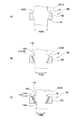
次に、本発明の一実施形態に係る杭保持装置に備わる内径調整部材の詳細な構成及び動作について、図面を使用しながら説明する。図7(A)乃至(C)は、本発明の一実施形態に係る杭保持装置でテーパ杭を保持した状態を示す説明図である。 Next, the detailed configuration and operation of the inner diameter adjusting member provided in the pile holding device according to one embodiment of the present invention will be described with reference to the drawings. Drawing 7 (A) thru / or (C) are explanatory views showing the state where the taper pile was held with the pile holding device concerning one embodiment of the present invention.
本発明の一実施形態に係る杭保持装置100は、保持筒体102の内周面側に内径調整部材110を取り付けることによって、1台の杭保持装置100で異なる杭径の既製杭10を安定して支持できる。
The
本実施形態では、内径調整部材110として、その内径方向の厚さが異なる調整部材111、112が使用される。具体的には、調整部材111は、外径1100mmの杭本体12を保持する場合に用いられ、調整部材112は、調整部材111の内径方向の厚さよりも長くて、外径1000mmの杭本体12を保持する場合に用いられる。
In the present embodiment, as the inner
それぞれの調整部材111、112の外径は、保持筒体102の支持側テーパ面102cの径と略同一である。一方、調整部材111の内径は、外径1100mmの杭側テーパ面14の径と略同一である。また、調整部材112の内径は、外径1000mmの杭側テーパ面14の径と略同一である。すなわち、これらの調整部材111、112の各内周面111c、112cは、それぞれ保持筒体102の支持側テーパ面102cと略平行な構成となっている。また、これらの調整部材111、112は、SS相当の強度の強い材料から形成される。
The outer diameters of the adjusting members 111 and 112 are substantially the same as the diameter of the support side tapered
また、各調整部材111、112は、保持具片103(図3参照)のそれぞれの内周面側にボルトやナット等の接続部材で脱着可能となっている。なお、内径調整部材110の取り付け方は、事前にボルトやナット等の接続部材で固定して取り付ける以外に、例えば、杭孔50の開口部50aに設置した保持筒体102に既製杭10を降ろす直前に内径調整部材110を差し込むように取り付けてもよい。
Each of the adjustment members 111 and 112 can be attached to and detached from each inner peripheral surface of the holder piece 103 (see FIG. 3) with a connecting member such as a bolt or a nut. In addition, the internal
このように、本実施形態では、内径調整部材110として、厚さの異なる調整部材111、112を保持筒体102の支持側テーパ面102cにそれぞれ取り付けることによって、保持筒体102の内径を所望の大きさとなるように縮径させる。すなわち、保持筒体102の内周側端部となる支持側テーパ面102cに内径調整部材110を取り付けることによって、1台の杭保持装置100で異なる外径の既製杭10を安定して支持できるように、支持可能な杭径の範囲を拡大している。
As described above, in this embodiment, the adjustment members 111 and 112 having different thicknesses are attached to the support side tapered
内径調整部材110として、調整部材111、112を使用しない場合及び使用する場合について、以下で具体的な例を用いて説明する。
The case where the adjustment members 111 and 112 are not used and the case where the adjustment members 111 and 112 are used as the inner
例えば、図7(A)に示すように、外径1200mmの既製杭10を杭保持装置100で支持する場合には、既製杭10の杭側テーパ面14をそのまま支持側テーパ面102cに当接させる。すなわち、保持筒体102の支持側テーパ面102cに調整部材111、112を取り付けずに、既製杭10を杭保持装置100で保持する。
For example, as shown in FIG. 7A, when the ready-made
一方、図7(B)に示すように、外径1100mmの既製杭10を杭保持装置100で支持する場合には、保持筒体102の支持側テーパ面102cに調整部材111を取り付ける。
On the other hand, as illustrated in FIG. 7B, when the ready-made
さらに、図7(C)に示すように、外径1000mmの既製杭10を杭保持装置100で支持する場合には、保持筒体102の支持側テーパ面102cに調整部材112を取り付ける。
Further, as shown in FIG. 7C, when the ready-made
このように、保持筒体102の内周側端部となる支持側テーパ面102cに、内径保持部材110として調整部材111、112を着脱可能な構成とすることによって、杭側テーパ面14が支持側テーパ面102c、又は調整部材111の内周面111c若しくは調整部材112の内周面112cの何れかに当接される。このため、既製杭10の杭本体12の外径が異なっても、1つの杭保持装置100でこれらの外径が異なる既製杭10を安定して支持できる。
Thus, the pile
換言すると、本実施形態では、内径調整部材110として、その内径方向の厚さが異なる複数の調整部材111、112を交換することによって、保持筒体102の内周側端部となる支持側テーパ面102cの内径を調整可能としている。すなわち、既製杭10の杭本体12の外径の大きさに適合した厚さを有する調整部材111、112を保持筒部102の内周面側に有する支持側テーパ面102cに取り付けることによって、1台の杭保持装置100で、外径の異なる既製杭10を安定して支持できるようになる。
In other words, in the present embodiment, as the inner
なお、内径調整部材110による保持筒体102の内径調整方法は、図7(A)乃至(C)に開示した内容に限定されない。内径調整部材110による内径調整方法の他の態様について、図面を使用しながら説明する。図8(A)乃至(C)は、本発明の一実施形態に係る杭保持装置でテーパ杭を他の態様で保持した状態を示す説明図である。また、図9(A)乃至(C)は、本発明の一実施形態に係る杭保持装置でテーパ杭を更に他の態様で保持した状態を示す説明図である。
Note that the inner diameter adjustment method of the holding
図8(A)乃至(C)に示す実施態様では、内径調整部材110として、その内径方向の厚さが略同一の複数の調整部材113、114を着脱する。これらの調整部材113、114を保持筒体102の内周側端部となる支持側テーパ面102cに着脱することによって、保持筒体102の支持側テーパ面102cの内径を所望の大きさに調整する。
In the embodiment shown in FIGS. 8A to 8C, as the inner
本実施形態では、調整部材113の外径は、保持筒体102の内径、すなわち支持側テーパ面102cの径と略同一である。また、調整部材113の内径は、外径1100mmのテーパ杭10の杭側テーパ面14の径と略同一である。
In the present embodiment, the outer diameter of the
一方、調整部材114の外径は、外径1100mmのテーパ杭10の杭側テーパ面14の径と略同一である。また、調整部材114の内径は、外径1000mmのテーパ杭10の杭側テーパ面14の径と略同一である。
On the other hand, the outer diameter of the
すなわち、これらの調整部材113、114の各内周面113c、114cは、それぞれ保持筒体102の支持側テーパ面102cと略平行な構成となっている。そして、外径1100mmの既製杭10を保持する場合には、内径調整部材110として、調整部材113が用いられ、外径1000mmの既製杭10を保持する場合には、内径調整部材110として、双方の調整部材113、114が用いられる。
That is, the inner
内径調整部材110として、調整部材113、114を使用しない場合及び使用する場合について、以下で具体的な例を用いて説明する。
The case where the
例えば、図8(A)に示すように、外径1200mmの既製杭10を杭保持装置100で支持する場合には、既製杭10の杭側テーパ面14をそのまま支持側テーパ面102cに当接させる。すなわち、内径調整部材110として、保持筒体102の支持側テーパ面102cに調整部材111、112を取り付けずに、既製杭10を杭保持装置100で保持する。
For example, as shown in FIG. 8A, when the ready-made
一方、図8(B)に示すように、外径1100mmの既製杭10を杭保持装置100で支持する場合には、内径調整部材110として、保持筒体102の支持側テーパ面102cに調整部材113を取り付ける。
On the other hand, as shown in FIG. 8B, when the ready-made
さらに、図8(C)に示すように、外径1000mmの既製杭10を杭保持装置100で支持する場合には、内径調整部材110として、調整部材113の内周面113cに調整部材114を取り付ける。
Further, as shown in FIG. 8C, when the ready-made
このように、図8(A)乃至(C)に示す実施態様では、内径調整部材110が杭本体12の外径の大きさに適合した厚さとなるように、保持筒体102の支持側テーパ面102cに調整部材113、114を取り付ける。このようにして、杭本体12の外径が異なっても、1台の杭保持装置100で、これらの既製杭10を安定して支持できる。
As described above, in the embodiment shown in FIGS. 8A to 8C, the support side taper of the holding
また、図9(A)乃至(C)に示す実施態様では、内径調整部材110として保持筒体102の支持側テーパ面102cに取り付ける調整部材115の鉛直方向における高さ位置を略鉛直方向へ移動させて変更することによって、保持筒体102の内径を所望の大きさに調整する。
Further, in the embodiment shown in FIGS. 9A to 9C, the height position in the vertical direction of the
具体的には、図9(A)に示すように、外径1100mmの既製杭10を杭保持装置100で支持する場合には、内径調整部材110として、保持筒体102の内周側端部となる支持側テーパ面102cに外径1100mmのテーパ杭用の調整部材115を取り付ける。すなわち、調整部材115として、前述した一実施形態の杭保持装置100の保持筒体102に取り付ける調整部材111と同じ仕様のものを取り付ける。
Specifically, as shown in FIG. 9A, when the ready-made
これに対して、図9(B)に示すように、外径1200mmの既製杭10を杭保持装置100で支持する場合には、調整部材115の上部が保持筒体102よりも上方に突出するように、即ち、調整部材115の内径が拡がるように調整部材115を内周側端部となる支持側テーパ面102cに取り付ける。換言すると、内径調整部材110として、保持筒体102の頂部側に外径1100mmのテーパ杭用の調整部材115をずらして取り付ける。
On the other hand, as shown in FIG. 9B, when the ready-made
さらに、図9(C)に示すように、外径1000mmの既製杭10を杭保持装置100で支持する場合には、調整部材115の下部が保持筒体102よりも下方に突出するように、即ち、調整部材115の内径が狭くなるように調整部材115を内周側端部となる支持側テーパ面102cに取り付ける。換言すると、内径調整部材110として、保持筒体102の底部側に外径1100mmのテーパ杭用の調整部材115をずらして取り付ける。
Furthermore, as shown in FIG. 9 (C), when the ready-made
このように、本実施態様では、内径調整部材110として、1つの外径対応用の調整部材115を杭保持装置100の頂部側又は底部側にずらして支持側テーパ面102cに取り付けることで、当該調整部材115の内径を杭本体12の外径の大きさに適合させる。このようにして、1台の杭保持装置100で杭本体12の異なる外径に対応して支持できるようになる。このため、異なる杭径に対応しても、既製杭10を安定して支持できる。
Thus, in this embodiment, as the inner
また、本実施態様では、調整部材115の内周面115cに所定の範囲内のゴム硬度を有するウレタンゴム等からなる緩衝部材120が設けられる。調整部材115の内周面115cの曲率は、例えば、外径1100mmの既製杭10の環状凸部18の曲率と一致した構成となっている。すなわち、この場合では、調整部材115の内周面115cの曲率は、外径1200mmや1000mmの既製杭10の環状凸部18の曲率と一致しない。
In this embodiment, the
このため、外径1200mmや1000mmの既製杭10を調整部材115で支持すると、当該既製杭10の杭側テーパ面14と調整部材115の内周面115cとの間に部分的に隙間が生じる。すなわち、杭側テーパ面14と調整部材115の内周面115cとの間に片当たりが生じる。しかしながら、調整部材115と既製杭10との間に介在された緩衝部材120がこの隙間に圧密されるため、既製杭10の杭側テーパ面14の全体を支持することができるようになる。
For this reason, when the ready-made
特に、緩衝部材120のゴム硬度を50度以上100度未満の範囲内とすることによって、大径化に伴って重量化した既製杭10を支持する際における既製杭10への衝撃を確実に緩和し、かつ杭径が異なった既製杭10を支持する場合における既製杭10の片当たりを無くして、安定した支持ができる。
In particular, by setting the rubber hardness of the
このように、本実施形態では、調整部材115の内周面115cに緩衝部材120を設けることによって、かかる曲率の変化に対応して緩衝部材120が環状凸部18に当接するようにしている。このため、外径が異なる既製杭10を支持する場合においても当該既製杭10を安定して支持できる。
As described above, in the present embodiment, the
緩衝部材120は、ゴム硬度が上記範囲内の材質であればよく、例えば、クロロプレンゴム、エチレンプロピレンゴム、ウレタンゴム、シリコンゴム、フッ素ゴム等のゴム系の材質や、ポリスチレン等の合成樹脂系の材質といった弾性材や緩衝材として使用されるものが適用される。本明細書中における「ゴム硬度」とは、ISO7619やJIS_K_6253の規格に基づいたデュロメータを計測器に用いて測定した弾性材や緩衝材の硬度をいう。
The
なお、本実施形態の杭保持装置100は、環状凸部18として杭側テーパ面14を有する既製杭10を保持する場合について取り上げているが、環状凸部18の形状は、杭側テーパ面14に限定されるものではなく、環状凸部18の形状に対応した内径調整部材110を併用することによって、他の態様の既製杭にも適用可能である。以下で環状凸部18の形状が異なる場合について説明する。
In addition, although the pile holding |
例えば、図10(A)に示すように、環状凸部である節部28を有する節杭20を支持する場合には、内径調整部材110として外径1000mmのテーパ杭用の調整部材116の頂部側に節受部材212がナット等の接続部材により取り付けられる。すなわち、調整部材116として、前述した一実施形態の杭保持装置100の保持筒体102に取り付ける調整部材112と同じ仕様のものを取り付ける。
For example, as shown in FIG. 10A, when supporting the
節受部材212の内周面212cは、調整部材116を保持筒体102の支持側テーパ面102cに取り付けた状態で、節部28の下部の杭側テーパ面28cと略平行な構成となっている。また、節受部材212の内周面212cの最下端による内径は、杭本体22の外径と略同一である。節受部材212の外周面212bの外径は、調整部材116の内周面116cの径と略同一である。そして、これらの調整部材116、212は、SS相当の材料から形成される。
The inner
保持筒体102で節杭20を保持する際には、節部28の杭側テーパ面28cが節受部材212の内周面212cに当接することで、節杭20を支持することができるようになる。また、節受部材212の鉛直方向における設置位置の変更や内径方向の厚さの調整、及び調整部材116の内径方向の厚さを調整することによって、節杭20の杭本体22の外径に対応して、安定した支持ができるようになる。
When holding the
一方、図10(B)に示すように、環状凸部として杭本体32の外周面側に拡頭部38が設けられた拡頭杭30を支持する場合には、調整部材116の頂部側に節受部材312をナット等の接続部材で取り付けて、拡頭杭30を支持することができる。また、保持筒体102の内周面側に支持側テーパ面102cが設けられていることから、節受部材312の鉛直方向における設置位置の変更や調整部材116の内径方向の厚さを調整することによって、拡頭杭30の杭本体32の外径に対応して、安定した支持が可能となる。
On the other hand, as shown in FIG. 10 (B), when supporting the expanded
上述した各実施態様では、既製杭10、節杭20、拡頭杭30の外周面12cにそれぞれ環状凸部18、28、38を設けるとともに、杭保持装置100の保持筒体102に支持側テーパ面102cを設けている。また、保持筒体102にその内径を所望の大きさに調整可能な内径調整部材110として各調整部材111、112、113、114、115、116、緩衝部材120及び節受部材212、312等を取り付けられる構成となっている。
In each embodiment mentioned above, while providing the annular
このため、既製杭10、節杭20、拡頭杭30を保持筒体102で支持する際に、保持筒体102の支持側テーパ面102cに既製杭10の環状凸部18、28、38からの荷重が分散されて、均等にかかり易くした上で、所望の大きさの外径に対応した既製杭10の安定した支持が可能となる。
For this reason, when supporting the ready-made
すなわち、大径化、重量化された既製杭としてテーパ杭10、節杭20、拡頭杭30を保持筒体102で支持する際に、定位置での安定した保持状態を維持することができる。換言すると、既製杭としてテーパ杭10、節杭20、拡頭杭30を杭孔50に建て込む過程において、杭保持装置100でこれらテーパ杭10、節杭20、拡頭杭30を保持する際に、各既製杭10、20、30がぶれることなく、より安定した状態で定位置にテーパ杭10、節杭20、拡頭杭30を略鉛直方向に保持することができる。
That is, when the
このため、従来のように杭の継ぎ足しをする際における杭保持にワイヤを使わないため、既製杭としてテーパ杭10、節杭20、拡頭杭30を継ぎ足しながら杭孔50に建て込む作業の効率が上がると同時に、かかる作業における安全性も向上する。また、下杭に上杭を継ぎ足して連結する際に、環状凸部18、28、38を有する下杭が支持側テーパ面102cを有する保持筒体102によって定位置に保持されるので、下杭と上杭を精度よく連結できる。
For this reason, since a wire is not used for the pile holding | maintenance at the time of adding a pile like the past, the efficiency of the work which builds in the
また、保持筒体102の内周面側の支持側テーパ面102cに所望の大きさに内径を調整可能な内径調整部材110を取り付けることによって、テーパ杭10、節杭20、拡頭杭30の杭本体12、22、32の外径に対応できる。このため、テーパ杭10、節杭20、拡頭杭30ががたつくことなく安定した杭保持が実現されるようになる。
Further, by attaching an inner
さらに、内径調整部材110を取り付けることによって、1台の杭保持装置100で保持対象となる既製杭としてテーパ杭10、節杭20、拡頭杭30の外径の適用範囲が拡大される。このため、杭の形状や外径が異なるものに対して、それぞれに適合した杭保持装置100を事前にそれぞれ用意する必要がなくなるので、維持・管理する上でコスト的にも労力的にも手間を低減することができる。
Furthermore, by attaching the inner
また、本実施形態の杭保持装置100では、内径調整部材110として各種形状及び厚さの調整部材111、112、113、114、115を保持筒体102の内周側端部となる支持側テーパ面102cに取り付けることによって、1台の杭保持装置100で保持対象となる既製杭10の種類と外径の適用範囲が拡大される。このため、1台の杭保持装置100で、使用箇所に適応した杭形状及び杭径の既製杭10、20、30をより安定した状態で保持して、継ぎ足せるようになる。
Further, in the
例えば、地盤の支持層では、より大きな先端支持力を確保するために、径の大きな節杭20等を使用し、支持層から地表に至るまでの間には、材料コストを低減した上で杭保持装置100を使用して、ワイヤを用いずに上杭と下杭を連結するワイヤレスでの杭の継ぎ足しを可能とするために、径の小さいテーパ杭10を使用し、地表側では、より耐震性を確保するために、径の大きな拡頭杭30を使用するような場合でも、1台の杭保持装置100で杭保持が可能となる。このため、1台の杭保持装置100でワイヤレスによる杭保持で各種の既製杭10、20、30を継ぎ足しながら、杭孔50に建て込む作業の効率と安全性を向上させた上で、既製杭10のトータル材料コストの削減等も実現される。
For example, in the ground support layer, a large-
なお、上記のように本発明の各実施形態について詳細に説明したが、本発明の新規事項及び効果から実体的に逸脱しない多くの変形が可能であることは、当業者には、容易に理解できるであろう。従って、このような変形例は、全て本発明の範囲に含まれるものとする。 Although each embodiment of the present invention has been described in detail as described above, it is easily understood by those skilled in the art that many modifications can be made without departing from the novel matters and effects of the present invention. It will be possible. Therefore, all such modifications are included in the scope of the present invention.
例えば、明細書又は図面において、少なくとも一度、より広義又は同義な異なる用語と共に記載された用語は、明細書又は図面のいかなる箇所においても、その異なる用語に置き換えることができる。また、杭保持装置の構成、動作も本発明の各実施形態で説明したものに限定されず、種々の変形実施が可能である。 For example, a term described with a different term having a broader meaning or the same meaning at least once in the specification or the drawings can be replaced with the different term in any part of the specification or the drawings. Further, the configuration and operation of the pile holding device are not limited to those described in the embodiments of the present invention, and various modifications can be made.
10 既製杭(テーパ杭)、12 杭本体、12c 外周面、14 テーパ面(杭側テーパ面)、18 環状凸部、20 節杭、30 拡頭杭、50 杭孔、50a 開口部、100 杭保持装置、102 保持筒体、102a 頂部、102b 底部、102c テーパ面(支持側テーパ面、環状凹部)、103 保持具片、104 フランジ部、105a、105c 回転用固定ピン、105b 開閉用脱着ピン、106 連結部、106a、106c 支持固定用連結部、106b 開閉用連結部、107 固定用連結部、110 内径調整部材、110c、111c、112c、113c,114c、115c、116c 内周面(内周側端部)、111、112、113,114、115、116 調整部材、120 緩衝部材、GN 地盤 10 ready-made piles (taper piles), 12 pile bodies, 12c outer peripheral surface, 14 taper surfaces (pile side taper surfaces), 18 annular convex parts, 20 joint piles, 30 head-expanded piles, 50 pile holes, 50a openings, 100 pile holders Device, 102 Holding cylinder, 102a Top, 102b Bottom, 102c Tapered surface (support side taper surface, annular recess), 103 Holder piece, 104 Flange, 105a, 105c Rotating fixing pin, 105b Opening / closing demounting pin, 106 Connecting portion, 106a, 106c Support fixing connecting portion, 106b Opening / closing connecting portion, 107 Fixing connecting portion, 110 Inner diameter adjusting member, 110c, 111c, 112c, 113c, 114c, 115c, 116c Inner peripheral surface (inner peripheral side end Part), 111, 112, 113, 114, 115, 116 adjustment member, 120 cushioning member, GN ground
Claims (6)
前記環状凸部に嵌装される環状凹部を有し、前記杭本体の前記環状凸部を囲って前記既製杭を保持する略円筒形状の保持筒体と、
前記保持筒体の内周側端部に取り付けられ、前記保持筒体の内周面の内径の大きさを調整可能な内径調整部材と、を備えることを特徴とする杭保持装置。 A pile holding device that holds the pre-made pile in a substantially vertical direction at the opening of the pile hole when building the pre-made pile having an annular convex portion on the outer peripheral surface of the pile body,
A substantially cylindrical holding cylinder that has an annular recess to be fitted to the annular protrusion, and holds the ready-made pile surrounding the annular protrusion of the pile body;
A pile holding device, comprising: an inner diameter adjusting member attached to an inner peripheral side end of the holding cylinder and capable of adjusting an inner diameter of an inner circumferential surface of the holding cylinder.
前記環状凹部は、前記保持筒体の前記内周面の底部側から頂部側に向けて一定の割合で拡径して形成されるテーパ面を有し、
前記内径調整部材の内側面は、前記内径調整部材を前記保持筒体の前記内周面に取り付けた状態で、前記保持筒体の前記テーパ面と略平行な構成となっており、
前記保持筒体で前記杭本体を保持する際に、前記杭側テーパ面が前記保持筒体の前記テーパ面又は前記内径調整部材の前記内側面の何れかに当接することを特徴とする請求項1に記載の杭保持装置。 The annular convex portion is formed integrally in an annular shape along the outer peripheral surface of the pile body, and is formed by expanding the diameter from a predetermined position of the outer peripheral surface in a direction having one end portion of the pile body at a constant rate. Has a pile-side taper surface,
The annular recess has a tapered surface formed by expanding the diameter from a bottom side to a top side of the inner peripheral surface of the holding cylinder at a certain rate,
The inner surface of the inner diameter adjusting member is configured to be substantially parallel to the tapered surface of the holding cylinder in a state where the inner diameter adjusting member is attached to the inner peripheral surface of the holding cylinder.
The pile-side tapered surface abuts on either the tapered surface of the holding cylinder or the inner side surface of the inner diameter adjusting member when holding the pile main body with the holding cylinder. The pile holding device according to 1.
Priority Applications (1)
| Application Number | Priority Date | Filing Date | Title |
|---|---|---|---|
| JP2014251918A JP6418493B2 (en) | 2014-12-12 | 2014-12-12 | Pile holding device |
Applications Claiming Priority (1)
| Application Number | Priority Date | Filing Date | Title |
|---|---|---|---|
| JP2014251918A JP6418493B2 (en) | 2014-12-12 | 2014-12-12 | Pile holding device |
Publications (2)
| Publication Number | Publication Date |
|---|---|
| JP2016113773A JP2016113773A (en) | 2016-06-23 |
| JP6418493B2 true JP6418493B2 (en) | 2018-11-07 |
Family
ID=56139796
Family Applications (1)
| Application Number | Title | Priority Date | Filing Date |
|---|---|---|---|
| JP2014251918A Active JP6418493B2 (en) | 2014-12-12 | 2014-12-12 | Pile holding device |
Country Status (1)
| Country | Link |
|---|---|
| JP (1) | JP6418493B2 (en) |
Families Citing this family (3)
| Publication number | Priority date | Publication date | Assignee | Title |
|---|---|---|---|---|
| JP6777875B1 (en) * | 2019-07-05 | 2020-10-28 | ジャパンパイル株式会社 | Construction method of holding a pile using a pile holding jig and a pile holding jig |
| CN111119173B (en) * | 2019-12-26 | 2021-03-05 | 太重(天津)滨海重型机械有限公司 | Pile sleeve with inner diameter adjusting device |
| JP7438532B2 (en) | 2020-04-24 | 2024-02-27 | 株式会社オトワコーエイ | Holding jig for cylindrical parts |
Family Cites Families (6)
| Publication number | Priority date | Publication date | Assignee | Title |
|---|---|---|---|---|
| JPS61121244U (en) * | 1985-01-14 | 1986-07-31 | ||
| JP2681270B2 (en) * | 1987-02-10 | 1997-11-26 | 大同コンクリート工業株式会社 | Pile holding device |
| AU735488B2 (en) * | 1997-08-28 | 2001-07-12 | Ihc Sea Steel Limited | Pile driving |
| JP4437234B2 (en) * | 2004-02-10 | 2010-03-24 | 三谷セキサン株式会社 | Method of burying ready-made piles |
| JP4555788B2 (en) * | 2006-02-27 | 2010-10-06 | 清水建設株式会社 | Pile holding device |
| JP5483912B2 (en) * | 2009-03-16 | 2014-05-07 | 日本高圧コンクリート株式会社 | Pile locking device and pile locking method |
-
2014
- 2014-12-12 JP JP2014251918A patent/JP6418493B2/en active Active
Also Published As
| Publication number | Publication date |
|---|---|
| JP2016113773A (en) | 2016-06-23 |
Similar Documents
| Publication | Publication Date | Title |
|---|---|---|
| JP6418493B2 (en) | Pile holding device | |
| CN105324538A (en) | Manhole having manhole cover of which height and slope can be adjusted | |
| BRPI1001843A2 (en) | Riser Implant | |
| KR102055269B1 (en) | Elasticity support | |
| ES2433266T3 (en) | Torsion limiter for a jet pump assembly | |
| JP6361201B2 (en) | Pile holding device | |
| JP6410096B2 (en) | Pile holding device | |
| JP6379554B2 (en) | Ready-made piles and support methods for ready-made piles | |
| JP2018204379A (en) | Joint structure for steel material | |
| JP6361200B2 (en) | Pile holding device | |
| KR20100138162A (en) | Jig for welding steel pipe sheet pile and welding method using the same | |
| JP5279674B2 (en) | Spacers for tubular structures in the cast-in-place concrete pile method | |
| JP4651683B2 (en) | Motor shaft of vertical shaft pump | |
| JP5198750B2 (en) | Lifting method using lifting jig | |
| JP6910235B2 (en) | Container reinforcement method and container support structure | |
| JP6604458B1 (en) | Pile holding jig, pile holding jig assembly, and construction method for holding the position of the pile | |
| JP5660876B2 (en) | Reactor vessel support structure and construction method of reactor vessel support structure | |
| JP6688612B2 (en) | Pile structure and method of assembling piles | |
| JP6924650B2 (en) | Reinforcing hardware for pipe support | |
| JP6250215B1 (en) | How to update existing piping | |
| JP4532952B2 (en) | Anchor spacer | |
| JP6917653B1 (en) | Support | |
| KR20140006276U (en) | Device for pulling cable drum | |
| JP2006315810A (en) | Drum adapter for winch, and method for installing the same | |
| JP2013079526A (en) | Rain cover tool for welding steel pipe pile |
Legal Events
| Date | Code | Title | Description |
|---|---|---|---|
| A621 | Written request for application examination |
Free format text: JAPANESE INTERMEDIATE CODE: A621 Effective date: 20171129 |
|
| A977 | Report on retrieval |
Free format text: JAPANESE INTERMEDIATE CODE: A971007 Effective date: 20180822 |
|
| TRDD | Decision of grant or rejection written | ||
| A01 | Written decision to grant a patent or to grant a registration (utility model) |
Free format text: JAPANESE INTERMEDIATE CODE: A01 Effective date: 20180914 |
|
| A61 | First payment of annual fees (during grant procedure) |
Free format text: JAPANESE INTERMEDIATE CODE: A61 Effective date: 20180927 |
|
| R150 | Certificate of patent or registration of utility model |
Ref document number: 6418493 Country of ref document: JP Free format text: JAPANESE INTERMEDIATE CODE: R150 |
|
| R250 | Receipt of annual fees |
Free format text: JAPANESE INTERMEDIATE CODE: R250 |
|
| R250 | Receipt of annual fees |
Free format text: JAPANESE INTERMEDIATE CODE: R250 |
|
| R250 | Receipt of annual fees |
Free format text: JAPANESE INTERMEDIATE CODE: R250 |
|
| R250 | Receipt of annual fees |
Free format text: JAPANESE INTERMEDIATE CODE: R250 |