JP6398627B2 - Heat dissipation sheet, method for manufacturing heat dissipation sheet, and method for manufacturing electronic device - Google Patents
Heat dissipation sheet, method for manufacturing heat dissipation sheet, and method for manufacturing electronic device Download PDFInfo
- Publication number
- JP6398627B2 JP6398627B2 JP2014228221A JP2014228221A JP6398627B2 JP 6398627 B2 JP6398627 B2 JP 6398627B2 JP 2014228221 A JP2014228221 A JP 2014228221A JP 2014228221 A JP2014228221 A JP 2014228221A JP 6398627 B2 JP6398627 B2 JP 6398627B2
- Authority
- JP
- Japan
- Prior art keywords
- film
- carbon nanotubes
- heat dissipation
- base film
- dissipation sheet
- Prior art date
- Legal status (The legal status is an assumption and is not a legal conclusion. Google has not performed a legal analysis and makes no representation as to the accuracy of the status listed.)
- Active
Links
Images


Classifications
-
- C—CHEMISTRY; METALLURGY
- C09—DYES; PAINTS; POLISHES; NATURAL RESINS; ADHESIVES; COMPOSITIONS NOT OTHERWISE PROVIDED FOR; APPLICATIONS OF MATERIALS NOT OTHERWISE PROVIDED FOR
- C09K—MATERIALS FOR MISCELLANEOUS APPLICATIONS, NOT PROVIDED FOR ELSEWHERE
- C09K5/00—Heat-transfer, heat-exchange or heat-storage materials, e.g. refrigerants; Materials for the production of heat or cold by chemical reactions other than by combustion
- C09K5/08—Materials not undergoing a change of physical state when used
- C09K5/14—Solid materials, e.g. powdery or granular
-
- C—CHEMISTRY; METALLURGY
- C01—INORGANIC CHEMISTRY
- C01B—NON-METALLIC ELEMENTS; COMPOUNDS THEREOF; METALLOIDS OR COMPOUNDS THEREOF NOT COVERED BY SUBCLASS C01C
- C01B32/00—Carbon; Compounds thereof
- C01B32/15—Nano-sized carbon materials
- C01B32/158—Carbon nanotubes
- C01B32/16—Preparation
-
- C—CHEMISTRY; METALLURGY
- C01—INORGANIC CHEMISTRY
- C01B—NON-METALLIC ELEMENTS; COMPOUNDS THEREOF; METALLOIDS OR COMPOUNDS THEREOF NOT COVERED BY SUBCLASS C01C
- C01B33/00—Silicon; Compounds thereof
- C01B33/113—Silicon oxides; Hydrates thereof
-
- C—CHEMISTRY; METALLURGY
- C01—INORGANIC CHEMISTRY
- C01B—NON-METALLIC ELEMENTS; COMPOUNDS THEREOF; METALLOIDS OR COMPOUNDS THEREOF NOT COVERED BY SUBCLASS C01C
- C01B2202/00—Structure or properties of carbon nanotubes
- C01B2202/08—Aligned nanotubes
-
- C—CHEMISTRY; METALLURGY
- C01—INORGANIC CHEMISTRY
- C01B—NON-METALLIC ELEMENTS; COMPOUNDS THEREOF; METALLOIDS OR COMPOUNDS THEREOF NOT COVERED BY SUBCLASS C01C
- C01B2202/00—Structure or properties of carbon nanotubes
- C01B2202/10—Filled nanotubes
-
- H—ELECTRICITY
- H01—ELECTRIC ELEMENTS
- H01L—SEMICONDUCTOR DEVICES NOT COVERED BY CLASS H10
- H01L2224/00—Indexing scheme for arrangements for connecting or disconnecting semiconductor or solid-state bodies and methods related thereto as covered by H01L24/00
- H01L2224/01—Means for bonding being attached to, or being formed on, the surface to be connected, e.g. chip-to-package, die-attach, "first-level" interconnects; Manufacturing methods related thereto
- H01L2224/10—Bump connectors; Manufacturing methods related thereto
- H01L2224/15—Structure, shape, material or disposition of the bump connectors after the connecting process
- H01L2224/16—Structure, shape, material or disposition of the bump connectors after the connecting process of an individual bump connector
- H01L2224/161—Disposition
- H01L2224/16151—Disposition the bump connector connecting between a semiconductor or solid-state body and an item not being a semiconductor or solid-state body, e.g. chip-to-substrate, chip-to-passive
- H01L2224/16221—Disposition the bump connector connecting between a semiconductor or solid-state body and an item not being a semiconductor or solid-state body, e.g. chip-to-substrate, chip-to-passive the body and the item being stacked
- H01L2224/16225—Disposition the bump connector connecting between a semiconductor or solid-state body and an item not being a semiconductor or solid-state body, e.g. chip-to-substrate, chip-to-passive the body and the item being stacked the item being non-metallic, e.g. insulating substrate with or without metallisation
-
- H—ELECTRICITY
- H01—ELECTRIC ELEMENTS
- H01L—SEMICONDUCTOR DEVICES NOT COVERED BY CLASS H10
- H01L2224/00—Indexing scheme for arrangements for connecting or disconnecting semiconductor or solid-state bodies and methods related thereto as covered by H01L24/00
- H01L2224/73—Means for bonding being of different types provided for in two or more of groups H01L2224/10, H01L2224/18, H01L2224/26, H01L2224/34, H01L2224/42, H01L2224/50, H01L2224/63, H01L2224/71
- H01L2224/732—Location after the connecting process
- H01L2224/73251—Location after the connecting process on different surfaces
- H01L2224/73253—Bump and layer connectors
Landscapes
- Chemical & Material Sciences (AREA)
- Organic Chemistry (AREA)
- Engineering & Computer Science (AREA)
- Materials Engineering (AREA)
- Inorganic Chemistry (AREA)
- Nanotechnology (AREA)
- Chemical Kinetics & Catalysis (AREA)
- Combustion & Propulsion (AREA)
- Physics & Mathematics (AREA)
- Thermal Sciences (AREA)
- Cooling Or The Like Of Semiconductors Or Solid State Devices (AREA)
- Carbon And Carbon Compounds (AREA)
- General Chemical & Material Sciences (AREA)
- Mechanical Engineering (AREA)
- Metallurgy (AREA)
- Catalysts (AREA)
- Cooling Or The Like Of Electrical Apparatus (AREA)
Description
本発明は、放熱シート、放熱シートの製造方法、及び電子装置の製造方法に関する。 The present invention relates to a heat dissipation sheet, a method for manufacturing a heat dissipation sheet, and a method for manufacturing an electronic device.
サーバやパーソナルコンピュータにおいては、CPU(Central Processing Unit)等の電子部品で発生する熱を外部に放熱すべく、電子部品にヒートスプレッダが固着される。 In a server or a personal computer, a heat spreader is fixed to an electronic component in order to dissipate heat generated by an electronic component such as a CPU (Central Processing Unit) to the outside.
そのヒートスプレッダと電子部品との間の熱抵抗が高いと、電子部品の熱を速やかにヒートスプレッダに伝えることができない。そのため、電子部品とヒートスプレッダとの間に、熱伝導性に優れた放熱シートを介在させることがある。 If the heat resistance between the heat spreader and the electronic component is high, the heat of the electronic component cannot be quickly transmitted to the heat spreader. For this reason, a heat radiation sheet having excellent thermal conductivity may be interposed between the electronic component and the heat spreader.
放熱シートには様々なタイプがある。インジウムシートも放熱シートの一例であるが、高価なインジウムを使用しているため放熱シートの低コスト化が難しい。 There are various types of heat dissipation sheets. An indium sheet is an example of a heat radiating sheet, but since expensive indium is used, it is difficult to reduce the cost of the heat radiating sheet.
そこで、インジウムシートに代わる放熱シートとして、カーボンナノチューブを用いた技術が検討されている。その技術においては、複数のカーボンナノチューブをシート上に立設することにより、各カーボンナノチューブの一端から他端に熱が輸送される。 Therefore, a technique using carbon nanotubes as a heat radiating sheet instead of the indium sheet has been studied. In the technique, heat is transported from one end of each carbon nanotube to the other end by standing a plurality of carbon nanotubes on a sheet.
カーボンナノチューブは、その熱伝導度が1500W/m・K〜3000W/m・K程度であって、インジウムの熱伝導度(80W/m・K)と比べて非常に高く、放熱シートに使用するのに好適である。 Carbon nanotubes have a thermal conductivity of about 1500 W / m · K to 3000 W / m · K, which is very high compared to the thermal conductivity of indium (80 W / m · K). It is suitable for.
放熱シートに接する電子部品の温度は電子部品の使用状況によって変わり、そのような温度変化に伴い電子部品も変形する。放熱シートが薄すぎると、電子部品の変形によって放熱シートが電子部品から離れてしまい、電子部品から放熱シートに熱を輸送するのが難しくなる。 The temperature of the electronic component in contact with the heat dissipation sheet varies depending on the usage state of the electronic component, and the electronic component is also deformed with such a temperature change. When the heat dissipation sheet is too thin, the heat dissipation sheet is separated from the electronic component due to deformation of the electronic component, and it becomes difficult to transport heat from the electronic component to the heat dissipation sheet.
これを防止するためには、各カーボンナノチューブを長くすることにより放熱シートをある程度厚くし、更に組み立て時に圧力を加えて放熱シートを電子部品に密着させるのが有効である。 In order to prevent this, it is effective to make the heat-dissipating sheet thick to some extent by lengthening each carbon nanotube, and to apply pressure during assembly to bring the heat-dissipating sheet into close contact with the electronic component.
しかしながら、前述のようにカーボンナノチューブを長くすると、カーボンナノチューブが全体として柔らかくなってしまうため、組み立て時の圧力にカーボンナノチューブが耐えられずに潰れてしまうおそれがある。 However, if the carbon nanotubes are lengthened as described above, the carbon nanotubes become soft as a whole, and the carbon nanotubes may not withstand the pressure during assembly and may collapse.
また、このようにカーボンナノチューブが柔らかくなると、温度変化に伴う電子部品の変形にカーボンナノチューブが追従できないおそれもある。 In addition, when the carbon nanotubes become soft as described above, there is a possibility that the carbon nanotubes cannot follow the deformation of the electronic component accompanying the temperature change.
これらの不都合を防止するために機械的に強固な膜でカーボンナノチューブをコーティングしてカーボンナノチューブを補強することも考えられるが、長いカーボンナノチューブの全体をコーティングするのは既存の技術では難しい。 In order to prevent these disadvantages, it may be possible to reinforce the carbon nanotubes by coating the carbon nanotubes with a mechanically strong film, but it is difficult to coat the entire long carbon nanotubes with existing technology.
開示の技術は、上記に鑑みてなされたものであって、放熱シート、放熱シートの製造方法、及び電子装置の製造方法において、コーティングによりカーボンナノチューブの全体を補強することを目的とする。 The disclosed technology has been made in view of the above, and an object of the present invention is to reinforce the entire carbon nanotubes by coating in a heat dissipation sheet, a method for manufacturing a heat dissipation sheet, and a method for manufacturing an electronic device.
以下の開示の一観点によれば、基板の上に下地膜として酸化シリコン膜、酸化アルミニウム膜及び窒化シリコン膜のいずれかを形成する工程と、前記下地膜上に、アルミニウム、チタン、タンタル、モリブデン、鉄、コバルト、ニッケル、金、銀、若しくは白金又はこれらの合金から触媒金属膜を形成する工程と、前記下地膜及び前記触媒金属膜の上に複数のカーボンナノチューブを成長させる工程と、加熱により前記下地膜の少なくとも一部及び前記触媒金属膜を蒸発させることにより、蒸発した前記下地膜の材料及び前記触媒金属膜の材料を含む被覆膜で前記カーボンナノチューブをコーティングする工程とを有する放熱シートの製造方法が提供される。 According to one aspect of the following disclosure, a step of forming any of a silicon oxide film, an aluminum oxide film, and a silicon nitride film as a base film on a substrate, and aluminum, titanium, tantalum, and molybdenum on the base film A step of forming a catalytic metal film from iron, cobalt, nickel, gold, silver, platinum or an alloy thereof, a step of growing a plurality of carbon nanotubes on the base film and the catalytic metal film , and heating. A step of coating the carbon nanotubes with a coating film containing the material of the base film and the material of the catalytic metal film by evaporating at least a part of the base film and the catalytic metal film. A manufacturing method is provided.
また、その開示の別の観点によれば、基板の上に下地膜として酸化シリコン膜、酸化アルミニウム膜及び窒化シリコン膜のいずれかを形成する工程と、前記下地膜上に、アルミニウム、チタン、タンタル、モリブデン、鉄、コバルト、ニッケル、金、銀、若しくは白金又はこれらの合金から触媒金属膜を形成する工程と、前記下地膜及び前記触媒金属膜の上に複数のカーボンナノチューブを成長させる工程と、加熱により前記下地膜の少なくとも一部及び前記触媒金属膜を蒸発させることにより、蒸発した前記下地膜の材料及び前記触媒金属膜の材料を含む被覆膜で前記カーボンナノチューブをコーティングする工程と、前記コーティングする工程の後、複数の前記カーボンナノチューブを備えた放熱シートを作製する工程と、前記放熱シートの表面と裏面の各々を、電子部品と放熱部材の各々に圧着する工程とを有する電子装置の製造方法が提供される。 According to another aspect of the disclosure, a step of forming any one of a silicon oxide film, an aluminum oxide film, and a silicon nitride film as a base film on a substrate; and aluminum, titanium, tantalum on the base film Forming a catalytic metal film from molybdenum, iron, cobalt, nickel, gold, silver, platinum or an alloy thereof, and growing a plurality of carbon nanotubes on the base film and the catalytic metal film ; Coating the carbon nanotubes with a coating film containing the material of the evaporated base film and the material of the catalytic metal film by evaporating at least a part of the base film and the catalytic metal film by heating; and After the coating step, a step of producing a heat radiating sheet comprising a plurality of the carbon nanotubes, and the heat radiating sheet Each of the front and back of the method of manufacturing an electronic device having a step of pressure bonding to each of the electronic component and the heat radiating member.
更に、その開示の他の観点によれば、複数のカーボンナノチューブと、前記カーボンナノチューブの側面に形成され、アルミニウム、チタン、タンタル、モリブデン、鉄、コバルト、ニッケル、金、銀、及び白金のいずれかを含む酸化シリコン、酸化アルミニウム及び窒化シリコンのいずれかの被覆膜とを有する放熱シートが提供される。 Further, according to another aspect of the disclosure, a plurality of carbon nanotubes and any one of aluminum, titanium, tantalum, molybdenum, iron, cobalt, nickel, gold, silver, and platinum are formed on a side surface of the carbon nanotube. There is provided a heat dissipation sheet having a coating film of any one of silicon oxide, aluminum oxide, and silicon nitride .
以下の開示によれば、カーボンナノチューブの根元にある下地膜の一部を加熱により蒸発させ、蒸発した下地膜の材料を含む被覆膜でカーボンナノチューブをコーティングするので、カーボンナノチューブの根元を含む全体を補強することができる。 According to the following disclosure, a part of the base film at the base of the carbon nanotube is evaporated by heating, and the carbon nanotube is coated with the coating film containing the evaporated base film material. Can be reinforced.
本実施形態の説明に先立ち、本願発明者が検討した事項について説明する。 Prior to the description of the present embodiment, items studied by the inventor will be described.
図1は、その検討に使用した電子装置の分解斜視図である。 FIG. 1 is an exploded perspective view of an electronic device used for the examination.
この電子装置1は、サーバやパーソナルコンピュータで使用されるものであって、配線基板2と電子部品3とを有する。
The
電子部品3は、CPU(Central Processing Unit)やGPU(Graphical Processing Unit)等のように使用時に発熱する半導体部品であって、複数のはんだバンプ6を介して配線基板2に実装される。
The
また、その電子部品3の上面には放熱シート4が設けられており、その放熱シート4の上にヒートスプレッダ5が密着する。
Further, a
このような構成によれば、電子部品3で発生した熱が放熱シート4を介して速やかにヒートスプレッダ5に伝わり、電子部品3の冷却を促すことができる。
According to such a configuration, heat generated in the
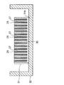
図2は、放熱シート4の模式断面図である。
FIG. 2 is a schematic cross-sectional view of the
図2に示すように、放熱シート4は熱伝導性に優れた複数のカーボンナノチューブ8を有しており、カーボンナノチューブ8を介して電子部品3からヒートスプレッダ5に熱が伝わる。
As shown in FIG. 2, the
電子部品3からカーボンナノチューブ8に効率的に熱を伝えるには、図2のように各カーボンナノチューブ8の両端がそれぞれ電子部品3とヒートスプレッダ5に接触しているのが好ましい。
In order to efficiently transfer heat from the
一方、図3は、一部のカーボンナノチューブ8の端部8aがヒートスプレッダ5から離れている場合の断面図である。温度変化によって電子部品3が変形した場合に、このように端部8aがヒートスプレッダ5から離れることがある。
On the other hand, FIG. 3 is a cross-sectional view when the
図4は、このような不都合を防止する方法について説明するための模式断面図である。 FIG. 4 is a schematic cross-sectional view for explaining a method for preventing such an inconvenience.
図4においては、カーボンナノチューブ8を長くして余長を持たせ、更に電子装置1の組み立て時に圧力を加えてカーボンナノチューブ8を余長分だけ縮ませている。これにより、カーボンナノチューブ8自身の弾力により、電子部品3やヒートスプレッダ5にカーボンナノチューブ8の端部8aが密着する。
In FIG. 4, the
電子部品3やヒートスプレッダ5に端部8aが確実に密着できる程度の余長をカーボンナノチューブ8に持たせるには、カーボンナノチューブ8の長さが100μm以下では足りず、カーボンナノチューブ8を150μm〜500μm程度に長くするのが好ましい。
In order to provide the
但し、このようにカーボンナノチューブ8を長くすると、カーボンナノチューブ8が柔らかくなってしまうため、組み立て時の圧力にカーボンナノチューブ8が耐えられずに潰れてしまうおそれがある。
However, if the
しかも、このようにカーボンナノチューブ8が柔らかくなることで、温度変化に伴う電子部品3の変形にカーボンナノチューブ8が追従できないおそれもある。
In addition, since the
そこで、本願発明者は、酸化アルミニウム膜等の機械的に強固な膜でカーボンナノチューブ8をコーティングしてカーボンナノチューブ8の弾性を高めようと考えた。
Therefore, the inventor of the present application considered to increase the elasticity of the
図5は、酸化アルミニウム膜9でカーボンナノチューブ8をコーティングした場合の放熱シート4の断面図である。
FIG. 5 is a cross-sectional view of the
酸化アルミニウム膜9によるコーティングでカーボンナノチューブ8の弾性が高まるため、組み立て時の圧力でカーボンナノチューブ8が潰れるのを抑制でき、更に温度変化に伴う電子部品3の変形にカーボンナノチューブ8が追従できると期待できる。
The coating with the
しかし、150μm以上の長いカーボンナノチューブ8の全長にわたって均一に酸化アルミニウム膜9を形成するのは難しい。ALD法を用いればアスペクト比が高い下地に優れた被覆性の酸化アルミニウム膜を形成できることが知られている。しかし、本願発明者の調査によれば、ALD法で酸化アルミニウム膜9を形成しても、長いカーボンナノチューブ8に十分な弾性を持たせるのが難しいことが判明した。
However, it is difficult to form the
以下に、長いカーボンナノチューブに十分な弾性を持たせることが可能な本実施形態について説明する。 In the following, an embodiment of the present invention capable of giving a long carbon nanotube sufficient elasticity will be described.
(第1実施形態)
本実施形態に係る放熱シートについて、その製造工程を追いながら説明する。
(First embodiment)
The heat dissipation sheet according to this embodiment will be described following the manufacturing process.
図6〜図8は、本実施形態に係る放熱シートの製造途中の断面図である。 6-8 is sectional drawing in the middle of manufacture of the thermal radiation sheet which concerns on this embodiment.
まず、図6(a)に示すように、基板20としてシリコン基板を用意し、その基板20の表面を熱酸化することにより下地膜21として厚さが300nm程度の酸化シリコン膜を形成する。
First, as shown in FIG. 6A, a silicon substrate is prepared as the
基板20の材料はシリコンに限定されず、酸化アルミニウム、酸化マグネシウム、及びガラスのいずれかを材料とする基板を用いてもよい。
The material of the
また、下地膜21も酸化シリコン膜に限定されない。例えば、酸化アルミニウム膜や窒化シリコン膜も下地膜21として形成し得る。
Further, the
次に、図6(b)に示すように、下地膜21の上にスパッタ法でアルミニウム膜を10nm程度の厚さに形成し、そのアルミニウム膜を下地金属膜22とする。
Next, as shown in FIG. 6B, an aluminum film is formed to a thickness of about 10 nm on the
下地金属膜22の材料としては、アルミニウムの他に、モリブデン、チタン、ハフニウム、ジルコニウム、ニオブ、バナジウム、タンタル、タングステン、銅、金、白金、パラジウム、チタンシリサイド、酸化アルミニウム、酸化チタン、及び窒化チタンがある。更に、これらの材料のいずれかを含む合金膜を下地金属膜22として形成してもよい。 As the material of the base metal film 22, in addition to aluminum, molybdenum, titanium, hafnium, zirconium, niobium, vanadium, tantalum, tungsten, copper, gold, platinum, palladium, titanium silicide, aluminum oxide, titanium oxide, and titanium nitride There is. Further, an alloy film containing any of these materials may be formed as the base metal film 22.
次いで、下地金属膜22の上にスパッタ法で鉄膜を2.5nm程度の厚さに形成し、その鉄膜を触媒金属膜23とする。 Next, an iron film having a thickness of about 2.5 nm is formed on the base metal film 22 by sputtering, and the iron film is used as the catalyst metal film 23.
触媒金属膜23の材料は鉄に限定されない。触媒金属膜23は、アルミニウム、チタン、タンタル、モリブデン、鉄、コバルト、ニッケル、金、銀、白金、又はこれらの合金から形成し得る。 The material of the catalytic metal film 23 is not limited to iron. The catalytic metal film 23 can be formed from aluminum, titanium, tantalum, molybdenum, iron, cobalt, nickel, gold, silver, platinum, or an alloy thereof.
更に、触媒金属膜23に代えて、触媒金属膜23と同一の材料を含む金属微粒子を下地金属膜22の上に付着させてもよい。この場合、金属微粒子は、微分型静電分級器等によって予め所定の直径のもののみが収集されて下地金属膜22の上に供給される。 Further, instead of the catalyst metal film 23, metal fine particles containing the same material as the catalyst metal film 23 may be attached on the base metal film 22. In this case, only fine metal particles having a predetermined diameter are collected in advance by a differential electrostatic classifier or the like and supplied onto the underlying metal film 22.
続いて、図7(a)に示すように、触媒金属膜23の触媒作用を利用してホットフィラメントCVD(Chemical Vapor Deposition)法により複数のカーボンナノチューブ25を成長させる。そのカーボンナノチューブ25は、下地膜21の作用によっり、基板20の法線方向nに沿って直線的に成長する。
Subsequently, as shown in FIG. 7A, a plurality of
カーボンナノチューブ25の成長条件は特に限定されない。この例では、原料ガスとしてエチレンガスとアルゴンガスとの混合ガスを用い、不図示の成長室内における原料ガスの総ガス圧力を1kPaとする。エチレンガスとアルゴンガスとの分圧比は、例えば1:9程度である。また、ホットフィラメントの温度は1000℃程度とする。
The growth conditions of the
なお、下地金属膜22と触媒金属膜23は、成長室内に原料ガスが導入された際に凝縮して粒状の金属粒24となり、その金属粒24の上にのみカーボンナノチューブ25が成長する。
Note that the base metal film 22 and the catalyst metal film 23 condense when the source gas is introduced into the growth chamber to form
この成長条件によれば、カーボンナノチューブ25の面密度は約1×10¹¹本/cm2となり、各カーボンナノチューブ25の直径は4nm〜8nmで平均直径は約6nmとなる。
According to this growth condition, the surface density of the
また、成長レートは4μm/minとなり、各カーボンナノチューブ25の長さは放熱シートに適した100μm〜500μm程度の長さとなる。
The growth rate is 4 μm / min, and the length of each
なお、各カーボンナノチューブ25においては、その中心軸から外側に向かって単層のグラフェンシートが3層〜6層程度積み重なり、その層数の平均値は4層程度となる。このように多層のグラフェンシートを積層してなるカーボンナノチューブは多層カーボンナノチューブとも呼ばれるが、単層カーボンナノチューブを形成してもよい。
In each
カーボンナノチューブ25の面密度は上記に限定されないが、カーボンナノチューブ25による放熱効果の実効を図るには、なるべく高い面密度、例えば1×10¹⁰本/cm2以上の面密度でカーボンナノチューブ25を形成するのが好ましい。
The surface density of the
更に、カーボンナノチューブ25の成膜方法は上記のホットフィラメントCVD法に限定されず、熱CVD法やリモートプラズマCVD法であってもよい。また、アセチレンに代えてメタン若しくはエチレン等の炭化水素類、又はエタノール若しくはメタノール等のアルコール類を炭素の原料としてもよい。
Further, the film formation method of the
次に、図7(b)に示すように、真空中又はアルゴン雰囲気において下地膜21を加熱することで、下地膜21からその材料21xである酸化シリコンを蒸発させる。これにより、材料21xがカーボンナノチューブ25の表面に再付着し、酸化シリコンの被覆膜27で各カーボンナノチューブ25がコーティングされる。
Next, as shown in FIG. 7B, the
材料21xは、カーボンナノチューブ25の根元25xから上昇していくので、根元25x付近で被覆膜27の膜厚が不十分となることがなく、根元25xを含むカーボンナノチューブ25の全体を被覆膜27でコーティングできる。
Since the material 21x rises from the
そして、その被覆膜27によってカーボンナノチューブ25の弾性が増し、カーボンナノチューブ25がその根元から補強されることになる。
Then, the elasticity of the
なお、このように下地膜21を蒸発させる際には、金属粒24の基となった触媒金属膜23(図6(b)参照)も蒸発する。よって、被覆膜27には、酸化シリコンだけでなく、触媒金属膜23の材料である鉄、コバルト、ニッケル、金、銀、及び白金のいずれかが含まれることになる。
Note that, when the
また、加熱により下地膜21の全てを蒸発させる必要はなく、下地膜21の表層部分のように下地膜21の少なくとも一部を蒸発させればよい。そして、このように下地膜21を蒸発させるには、例えば、基板20の上方に抵抗加熱型のヒータを配置し、そのヒータの輻射熱により下地膜21を加熱すればよい。
Further, it is not necessary to evaporate all of the
更に、下地膜21として酸化アルミニウム膜や窒化シリコン膜を形成する場合には、これらの膜の材料を含んだ被覆膜27が形成されることになる。
Furthermore, when an aluminum oxide film or a silicon nitride film is formed as the
下地膜21の加熱プロファイルは特に限定されない。
The heating profile of the
図11は、その加熱プロファイルの一例を示すグラフである。 FIG. 11 is a graph showing an example of the heating profile.
この例では、100℃/分程度の昇温レートで下地膜21を室温(24℃〜25℃)から昇温させる昇温ステップS1を行った後、下地膜21を最高温度Tmaxに維持する加熱ステップS2を行う。その後、降温ステップS3において、45℃/分〜50℃/分程度の降温レートで下地膜21を室温まで冷却する。
In this example, after performing a temperature raising step S 1 for raising the temperature of the
なお、最高温度Tmaxは、下地膜21の融点よりも僅かに高い温度である。下地膜21として融点が約950℃の酸化シリコン膜を形成する場合には、最高温度Tmaxを1000℃〜1010℃程度に設定し得る。
The maximum temperature T max is a temperature slightly higher than the melting point of the
更に、最高温度Tmaxに維持する時間Tは、カーボンナノチューブ25を十分に補強できる程度の厚さの被覆膜27ができるような時間であり、例えば、5分〜10分程度とし得る。
Furthermore, the time T for maintaining the maximum temperature T max is a time for forming the
次に、図8(a)に示すように、熱可塑性の樹脂30をその融解温度よりも高い温度に加熱することで液状にし、各カーボンナノチューブ25の間に樹脂30を含浸させる。その樹脂30として、例えば、融解温度が135℃〜145℃のヘンケル株式会社製のMicromelt6239ホットメルト充填材を使用する。この樹脂は、225℃での粘度が5.5Pa〜8.5Pa程度である。
Next, as shown in FIG. 8A, the
そして、この樹脂30により、各カーボンナノチューブ25の先端25zは覆われることになる。
Then, the
次いで、図8(b)に示すように、樹脂30が室温まで冷えたところで下地膜21からカーボンナノチューブ25と樹脂30とを剥離し、カーボンナノチューブ25と樹脂30とを備えた放熱シート31を得る。
Next, as shown in FIG. 8B, when the
このとき、樹脂30が複数のカーボンナノチューブ25を保持する保持部材として機能するため、剥離時に各カーボンナノチューブ25が飛散するのを防止できると共に、放熱シート31の取り扱いが容易となる。
At this time, since the
その放熱シート31の厚さは、カーボンナノチューブ25の長さと略同じであって、100μm〜500μm程度である。
The thickness of the
また、放熱シート31は相対する裏面31aと表面31bとを有しており、裏面31aから表面31bに向けてカーボンナノチューブ25が延びる。そして、裏面31aからはカーボンナノチューブ25が露出するのに対し、表面31b側のカーボンナノチューブ25は樹脂30で覆われた状態となる。
The
これ以降は、放熱シート31を備えた電子装置の製造工程に移る。
Thereafter, the process proceeds to the manufacturing process of the electronic device provided with the
図9〜図10は、本実施形態に係る電子装置の製造途中の断面図である。 9 to 10 are cross-sectional views of the electronic device according to the present embodiment during manufacture.
まず、図9に示すように、加熱により樹脂30をある程度軟化させる。そして、軟化した樹脂30の粘着力を利用して、放熱シート31の表面31bを放熱部材32に圧着する。放熱部材32は、ヒートスプレッダやヒートシンクであって、例えばアルミニウムや銅等のように熱伝導性の良好な金属から形成される。
First, as shown in FIG. 9, the
次に、図10に示す断面構造を得るまでの工程について説明する。 Next, steps required until a sectional structure shown in FIG.
まず、はんだバンプ36を介して半導体素子33が接続された配線基板34を用意する。
First, a
そして、樹脂製のシーラント35で配線基板34に放熱部材32を固定する。
The
これと同時に、加熱により樹脂30を軟化させた後、軟化した樹脂30の粘着力を利用して、放熱シート31の裏面31aを半導体素子33に圧着する。この圧着によりカーボンナノチューブ25が若干縮まり、そのカーボンナノチューブ25の弾力によって放熱シート31が放熱部材32と半導体素子33の各々に密着する。
At the same time, after the
ここで、前述のようにカーボンナノチューブ25の弾性が被覆膜27によって増しているため、圧着時の圧力によってカーボンナノチューブ25が大きく潰れることはなく、カーボンナノチューブ25が圧着時の圧力に耐えられるようになる。
Here, since the elasticity of the
しかも、カーボンナノチューブ25が100μm〜500μmと長いので、圧着時に縮むだけの余長がカーボンナノチューブ25に生ずる。よって、その余長だけカーボンナノチューブ25を縮ませることにより、常にカーボンナノチューブ25に弾力を生じさせることができ、実使用下の温度変化で半導体素子33が変形してもそれに放熱シート31が追従できるようになる。
In addition, since the
以上により、本実施形態に係る電子装置39の基本構造が完成する。
Thus, the basic structure of the
上記した本実施形態によれば、図7(b)の工程において下地膜21を蒸発させることで、その下地膜21の材料でカーボンナノチューブ25をその根元25xからコーティングでき、根元25xを含むカーボンナノチューブ25の全体を均一に補強できる。
According to the present embodiment described above, by evaporating the
しかも、コーティングするには下地膜21を加熱するだけでよいため、簡単にカーボンナノチューブ25の弾性を高めることができる。
In addition, since it is only necessary to heat the
本願発明者は、本実施形態の効果を確認するために様々な調査を行った。その調査結果について以下に説明する。 The inventor of the present application has conducted various investigations in order to confirm the effect of the present embodiment. The survey results will be described below.
まず、本願発明者は、上記のようにして被覆膜27が形成されたカーボンナノチューブ25をSEM(Scanning Electron Microscope)で観察した。
First, the inventor of the present application observed the
図12〜図14は、そのSEM像を元にして描いた図である。 12 to 14 are diagrams drawn based on the SEM image.
なお、このカーボンナノチューブ25の長さは200μmである。
The length of the
図12(a)〜(d)はカーボンナノチューブ25の根元25xの図である。この調査では、図11における最高温度Tmaxを1000℃とし、最高温度Tmaxに維持する時間Tを1分(図12(a))、3分(図12(b))、5分(図12(c))、及び10分(図12(d))とした。これについては後述の図13(a)〜(d)でも同様である。
12A to 12D are views of the
図12(a)〜(d)に示すように、カーボンナノチューブ25の根元25xには、下地膜21を材料とする被覆膜27が形成されている。
As shown in FIGS. 12A to 12D, a
図13(a)〜(d)は、根元25xよりも上のカーボンナノチューブ25の中央付近の図である。
13A to 13D are views in the vicinity of the center of the
図13(a)〜(d)に示すように、カーボンナノチューブ25の中央付近においても被覆膜27が形成される。
As shown in FIGS. 13A to 13D, the
そして、図14(a)、(b)は、カーボンナノチューブ25の先端25zの図である。
14A and 14B are views of the
先端25zのSEM像の取得に際しては、図11における最高温度Tmaxを1000℃とし、最高温度Tmaxに維持する時間Tを5分(図14(a))、及び10分(図14(b))とした。
When acquiring the SEM image of the
図14(a)、(b)に示すように、カーボンナノチューブ25の先端25zにも被覆膜27が形成されている。
As shown in FIGS. 14A and 14B, a
上記した図12〜図14の調査結果より、下地膜21を加熱して蒸発させることで、カーボンナノチューブ25の根元25x、中央付近、及び先端25zの各部位の全てに被覆膜27を形成できることが確認できた。
From the above-described investigation results of FIGS. 12 to 14, the
次に、本願発明者は、被覆膜27でコーティングされたカーボンナノチューブ25の伝熱特性について調査した。
Next, the inventor of the present application investigated the heat transfer characteristics of the
その調査結果を図15に示す。 The survey results are shown in FIG.
図15の横軸は、図11において最高温度Tmaxに維持する時間Tを表す。また、縦軸は、カーボンナノチューブ25をその根元25xから加熱した場合における、根元25xと先端25zとの温度差Δを表す。
The horizontal axis in FIG. 15 represents time T for maintaining the maximum temperature T max in FIG. The vertical axis represents the temperature difference Δ between the
その温度差Δが小さいほど、根元25xから先端25zに速やかに熱が伝わり、カーボンナノチューブ25の伝熱特性が良いということになる。
The smaller the temperature difference Δ, the faster the heat is transferred from the
図15に示すように、時間Tが1分〜10分の間では温度差Δが大きく上昇することはない。この結果より、カーボンナノチューブ25を被覆膜27でコーティングしても、カーボンナノチューブ25の伝熱特性が大きく劣化することはないことが明らかとなった。
As shown in FIG. 15, the temperature difference Δ does not increase significantly when the time T is between 1 minute and 10 minutes. From this result, it became clear that even if the
更に、本願発明者は、被覆膜27でコーティングされたカーボンナノチューブ25の機械特性について調査した。
Furthermore, the inventor of the present application investigated the mechanical properties of the
その調査結果を図16に示す。 The result of the investigation is shown in FIG.
図16の横軸は、図11において最高温度Tmaxに維持する時間Tを表す。また、縦軸は、カーボンナノチューブ25に対してその長手方向から圧力を加えてカーボンナノチューブ25を収縮させた場合に、収縮前と収縮後のカーボンナノチューブ25の長さの比Pの百分率である。
The horizontal axis in FIG. 16 represents time T during which the maximum temperature Tmax is maintained in FIG. The vertical axis represents the percentage of the length ratio P of the
その比Pが大きいほどカーボンナノチューブ25が縮みにくく、カーボンナノチューブ25の弾性が高いということになる。
As the ratio P is larger, the
図16に示すように、時間Tの増加と共に比Pは増加し、その後、時間Tが5分程度のところで比Pは減少に転じる。 As shown in FIG. 16, the ratio P increases as the time T increases, and then the ratio P starts to decrease when the time T is about 5 minutes.
特に、時間Tが5分と10分の場合では、ALD法により被覆膜27を形成した場合と比較して比Pが大きくなり、ALD法よりも本実施形態に従って被覆膜27を形成した方がカーボンナノチューブ25の機械的強度が増すことが明らかとなった。
In particular, when the time T is 5 minutes and 10 minutes, the ratio P is larger than when the
(第2実施形態)
本実施形態では、以下のようにして放熱シートを熱が伝わり易いようにする。
(Second Embodiment)
In the present embodiment, heat is easily transmitted to the heat dissipation sheet as follows.
図17〜図18は、本実施形態に係る放熱シートの製造途中の断面図である。 17-18 is sectional drawing in the middle of manufacture of the thermal radiation sheet which concerns on this embodiment.
なお、図17〜図18において、第1実施形態で説明したのと同じ要素には第1実施形態におけるのと同じ符号を付し、以下ではその説明を省略する。 17 to 18, the same elements as those described in the first embodiment are denoted by the same reference numerals as those in the first embodiment, and the description thereof is omitted below.
まず、第1実施形態の図6(a)〜図8(a)の工程を行うことにより、図17(a)に示すように、各カーボンナノチューブ25の先端25zが樹脂30で覆われた構造を作製する。
First, by performing the steps of FIG. 6A to FIG. 8A of the first embodiment, as shown in FIG. 17A, the
次いで、図17(b)に示すように、樹脂30の表面を酸素プラズマでドライエッチングすることにより、カーボンナノチューブ25の先端25zに形成された被覆膜27を樹脂30から表出させる。
Next, as shown in FIG. 17B, the surface of the
このドライエッチングは、例えば、不図示のエッチングチャンバ内における酸素ガスの圧力を20mTorrに維持しつつ、パワーが50Wの高周波電力でその酸素ガスをプラズマ化して数分間行われる。 For example, this dry etching is performed for several minutes by converting the oxygen gas into plasma with high frequency power of 50 W while maintaining the pressure of oxygen gas in an etching chamber (not shown) at 20 mTorr.
このエッチング条件に対し、被覆膜27のエッチング速度は樹脂30のそれよりも遅いため、エッチングが終了した時点で被覆膜27はカーボンナノチューブ25の先端25zに残存する。
Since the etching rate of the
次いで、図18(a)に示すように、CF4ガスをエッチングガスとして使用するドライエッチングにより、カーボンナノチューブ25の先端25zに形成されている被覆膜27をエッチングして、樹脂30から先端25zを表出させる。
Next, as shown in FIG. 18A, the
CF4ガスに対して樹脂30はマスクとして機能するため、カーボンナノチューブ25の側面に形成されている部分の被覆膜27はエッチング雰囲気から保護される。
Since the
このエッチングの条件は特に限定されない。例えば、不図示のエッチングチャンバ内におけるCF4ガスの圧力を15mTorrに維持しつつ、パワーが50Wの高周波電力でそのCF4ガスをプラズマ化し、数分間だけこのエッチングを行えばよい。 The etching conditions are not particularly limited. For example, while maintaining the pressure of CF 4 gas in an etching chamber (not shown) at 15 mTorr, the CF 4 gas is made into plasma with a high frequency power of 50 W, and this etching is performed only for several minutes.
その後、図18(b)に示すように、下地膜21からカーボンナノチューブ25と樹脂30とを剥離し、カーボンナノチューブ25と樹脂30とを備えた放熱シート31を得る。
Thereafter, as shown in FIG. 18B, the
裏面31aのみからカーボンナノチューブ25が露出する第1実施形態(図8(b)参照)とは異なり、本実施形態では放熱シート31の裏面31aと表面31bの両方からカーボンナノチューブ25が露出する。
Unlike the first embodiment (see FIG. 8B) in which the
この後は、第1実施形態の図9〜図10の工程を行うことにより、図19の断面図に示すような本実施形態に係る電子装置39の基本構造を得る。
Thereafter, the basic structure of the
以上説明した本実施形態によれば、放熱シート31の裏面31aと表面31bの両方からカーボンナノチューブ25が露出しているため、放熱部材32と半導体素子33の両方がカーボンナノチューブ25に接触する。
According to the present embodiment described above, since the
よって、半導体素子33の熱がカーボンナノチューブ25を介して速やかに放熱部材32に伝わり、半導体素子33を効率的に冷却することができる。
Therefore, the heat of the
(第3実施形態)
第1及び第2実施形態では各カーボンナノチューブ25の間に樹脂30を含浸させたが、以下のようにして樹脂30を省いてもよい。
(Third embodiment)
In the first and second embodiments, the
図20〜図24は、本実施形態に係る電子装置の製造途中の断面図である。図20〜図24において、第1、第2実施形態で説明したのと同じ要素にはこれらの実施形態におけるのと同じ符号を付し、以下ではその説明を省略する。 20-24 is sectional drawing in the middle of manufacture of the electronic device which concerns on this embodiment. 20 to 24, the same elements as those described in the first and second embodiments are denoted by the same reference numerals as those in these embodiments, and the description thereof is omitted below.
まず、第1実施形態の図6(a)〜図7(b)の工程を行うことにより、図20に示すように、各カーボンナノチューブ25が被覆膜27でコーティングされた構造を得る。
First, by performing the steps of FIGS. 6A to 7B of the first embodiment, a structure in which each
これと共に、放熱部材32を用意し、その放熱部材32の表面に接着性の樹脂41を塗布する。
At the same time, a
次いで、図21に示すように、カーボンナノチューブ25の先端25zに形成されている被覆膜27を樹脂41に接触させて、樹脂41を介して各カーボンナノチューブ25を放熱部材32に接着する。
Next, as shown in FIG. 21, the
そして、図22に示すように、放熱部材32から基板20を引き上げることにより、下地膜21からカーボンナノチューブ25を剥離する。これにより、複数のカーボンナノチューブ25を備えた放熱シート31が放熱部材32側に残される。
Then, as shown in FIG. 22, the
その放熱シート31は、カーボンナノチューブ25の一方の端部25aが位置する裏面31aと、カーボンナノチューブ25の他方の端部25bが位置する表面31bとを有し、裏面31aから表面31bに向かってカーボンナノチューブ25が延びる。
The
次いで、図23に示すように、半導体素子33を備えた配線基板34を用意し、その半導体素子33の表面に接着性の樹脂42を塗布する。
Next, as shown in FIG. 23, a
そして、放熱部材32と半導体素子33とを位置合わせして、半導体素子33の上方に放熱シート31を位置させる。
Then, the
なお、その放熱部材32の縁には予めシーラント35を設けておく。
A
その後、図24に示すように、半導体素子33に向けて放熱部材32を下していき、放熱シート31の各カーボンナノチューブ25を樹脂42に圧着し、樹脂42により放熱シート31を半導体素子33に接着する。
Thereafter, as shown in FIG. 24, the
このように圧着しても、被覆膜27により各カーボンナノチューブ25の弾性が高められているので、各カーボンナノチューブ25が大きく潰れるのが抑制される。
Even when pressure bonding is performed in this way, the elasticity of the
以上により、本実施形態に係る電子装置39の基本構造を得る。
As described above, the basic structure of the
上記した本実施形態によれば、温度変化で半導体素子33が変形しても、被覆膜27によって弾性が高められた各カーボンナノチューブ25が半導体素子33の変形に追従でき、カーボンナノチューブ25を介して半導体素子33を放熱部材32に放熱できる。
According to the above-described embodiment, even if the
以上説明した各実施形態に関し、更に以下の付記を開示する。 The following additional notes are disclosed for each embodiment described above.
(付記1) 基板の上に下地膜を形成する工程と、
前記下地膜の上に複数のカーボンナノチューブを成長させる工程と、
加熱により前記下地膜の少なくとも一部を蒸発させることにより、蒸発した前記下地膜の材料を含む被覆膜で前記カーボンナノチューブをコーティングする工程と、
を有することを特徴とする放熱シートの製造方法。
(Appendix 1) Forming a base film on a substrate;
Growing a plurality of carbon nanotubes on the base film;
Coating the carbon nanotubes with a coating film containing the evaporated material of the base film by evaporating at least a part of the base film by heating; and
A method of manufacturing a heat dissipation sheet, comprising:
(付記2) 前記被覆膜を形成した後、複数の前記カーボンナノチューブの間に樹脂を含浸させる工程を更に有することを特徴とする付記1に記載の放熱シートの製造方法。
(Additional remark 2) After forming the said coating film, it further has the process of impregnating resin between the said some carbon nanotube, The manufacturing method of the thermal radiation sheet of
(付記3) 前記樹脂をマスクにしながら前記カーボンナノチューブの先端に形成された前記被覆膜をエッチングすることにより、前記樹脂から前記先端を表出させる工程を更に有することを特徴とする付記2に記載の放熱シートの製造方法。
(Supplementary note 3) The
(付記4) 前記被覆膜をエッチングする前に、前記樹脂の表面をエッチングすることにより、前記先端に形成された前記被覆膜を前記樹脂から表出させる工程を更に有することを特徴とする付記3に記載の放熱シートの製造方法。
(Supplementary Note 4) The method further includes the step of exposing the coating film formed at the tip from the resin by etching the surface of the resin before etching the coating film. The manufacturing method of the heat-radiation sheet of
(付記5) 基板の上に下地膜を形成する工程と、
前記下地膜の上に複数のカーボンナノチューブを成長させる工程と、
加熱により前記下地膜の少なくとも一部を蒸発させることにより、蒸発した前記下地膜の材料を含む被覆膜で前記カーボンナノチューブをコーティングする工程と、
前記コーティングする工程の後、複数の前記カーボンナノチューブを備えた放熱シートを作製する工程と、
前記放熱シートの表面と裏面の各々を、電子部品と放熱部材の各々に圧着する工程と、
を有することを特徴とする電子装置の製造方法。
(Appendix 5) A step of forming a base film on a substrate;
Growing a plurality of carbon nanotubes on the base film;
Coating the carbon nanotubes with a coating film containing the evaporated material of the base film by evaporating at least a part of the base film by heating; and
After the coating step, a step of producing a heat dissipation sheet comprising a plurality of the carbon nanotubes;
Crimping the front and back surfaces of the heat dissipation sheet to each of the electronic component and the heat dissipation member;
A method for manufacturing an electronic device, comprising:
(付記6) 前記放熱シートを作製する工程は、
複数の前記カーボンナノチューブの間に樹脂を含浸させる工程と、
前記樹脂を含浸させる工程の後、前記下地膜から前記樹脂と前記カーボンナノチューブを剥離して、前記樹脂と前記カーボンナノチューブとを前記放熱シートとする工程とを有することを特徴とする付記5に記載の電子装置の製造方法。
(Appendix 6) The step of producing the heat dissipation sheet includes
Impregnating a resin between the plurality of carbon nanotubes;
The method according to
(付記7) 前記放熱シートを圧着する工程は、
加熱により前記樹脂を軟化させて、前記樹脂を前記電子部品に接着する工程と、
加熱により前記樹脂を軟化させて、前記樹脂を前記放熱部材に接着する工程とを有することを特徴とする付記6に記載の電子装置の製造方法。
(Appendix 7) The step of pressure-bonding the heat dissipation sheet includes
Softening the resin by heating and bonding the resin to the electronic component;
The method for manufacturing an electronic device according to
(付記8) 前記放熱シートを作製する工程は、前記下地膜から複数の前記カーボンナノチューブを剥離して、剥離後の複数の前記カーボンナノチューブを前記放熱シートとすることにより行われることを特徴とする付記5に記載の電子装置の製造方法。
(Additional remark 8) The process of producing the said heat radiating sheet is performed by peeling the said some carbon nanotube from the said base film, and making the said some carbon nanotube after peeling into the said heat radiating sheet, It is characterized by the above-mentioned. The method for manufacturing an electronic device according to
(付記9) 複数のカーボンナノチューブと、
前記カーボンナノチューブの側面に形成され、アルミニウム、チタン、タンタル、モリブデン、鉄、コバルト、ニッケル、金、銀、及び白金のいずれかを含む酸化シリコンの被覆膜と、
を有することを特徴とする放熱シート。
(Appendix 9) A plurality of carbon nanotubes,
A coating film of silicon oxide formed on a side surface of the carbon nanotube and containing any of aluminum, titanium, tantalum, molybdenum, iron, cobalt, nickel, gold, silver, and platinum;
A heat dissipating sheet characterized by comprising:
(付記10) 複数の前記カーボンナノチューブの間に含浸された樹脂を更に有することを特徴とする付記9に記載の放熱シート。
(Supplementary note 10) The heat dissipation sheet according to
1…電子装置、2…配線基板、3…電子部品、4…放熱シート、5…ヒートスプレッダ、6…はんだバンプ、8、25…カーボンナノチューブ、8a…端部、9…酸化アルミニウム膜、20…基板、21…下地膜、22…下地金属膜、23…触媒金属膜、24…金属粒、25a、25b…端部、25x…根元、25z…先端、27…被覆膜、30…樹脂、31…放熱シート、31a…裏面、31b…表面、32…放熱部材、33…半導体素子、34…配線基板、35…シーラント、36…はんだバンプ、39…電子装置、41、42…樹脂。
DESCRIPTION OF
Claims (5)
前記下地膜上に、アルミニウム、チタン、タンタル、モリブデン、鉄、コバルト、ニッケル、金、銀、若しくは白金又はこれらの合金から触媒金属膜を形成する工程と、
前記下地膜及び前記触媒金属膜の上に複数のカーボンナノチューブを成長させる工程と、
加熱により前記下地膜の少なくとも一部及び前記触媒金属膜を蒸発させることにより、蒸発した前記下地膜の材料及び前記触媒金属膜の材料を含む被覆膜で前記カーボンナノチューブをコーティングする工程と、
を有することを特徴とする放熱シートの製造方法。 Forming a silicon oxide film, an aluminum oxide film, or a silicon nitride film as a base film on a substrate;
Forming a catalytic metal film from aluminum, titanium, tantalum, molybdenum, iron, cobalt, nickel, gold, silver, platinum, or an alloy thereof on the base film;
Growing a plurality of carbon nanotubes on the base film and the catalytic metal film ;
Coating the carbon nanotubes with a coating film containing the material of the base film and the material of the catalytic metal film by evaporating at least a part of the base film and the catalytic metal film by heating; and
A method of manufacturing a heat dissipation sheet, comprising:
前記下地膜上に、アルミニウム、チタン、タンタル、モリブデン、鉄、コバルト、ニッケル、金、銀、若しくは白金又はこれらの合金から触媒金属膜を形成する工程と、
前記下地膜及び前記触媒金属膜の上に複数のカーボンナノチューブを成長させる工程と、
加熱により前記下地膜の少なくとも一部及び前記触媒金属膜を蒸発させることにより、蒸発した前記下地膜の材料及び前記触媒金属膜の材料を含む被覆膜で前記カーボンナノチューブをコーティングする工程と、
前記コーティングする工程の後、複数の前記カーボンナノチューブを備えた放熱シートを作製する工程と、
前記放熱シートの表面と裏面の各々を、電子部品と放熱部材の各々に圧着する工程と、
を有することを特徴とする電子装置の製造方法。 Forming a silicon oxide film, an aluminum oxide film, or a silicon nitride film as a base film on a substrate;
Forming a catalytic metal film from aluminum, titanium, tantalum, molybdenum, iron, cobalt, nickel, gold, silver, platinum, or an alloy thereof on the base film;
Growing a plurality of carbon nanotubes on the base film and the catalytic metal film ;
Coating the carbon nanotubes with a coating film containing the material of the base film and the material of the catalytic metal film by evaporating at least a part of the base film and the catalytic metal film by heating; and
After the coating step, a step of producing a heat dissipation sheet comprising a plurality of the carbon nanotubes;
Crimping the front and back surfaces of the heat dissipation sheet to each of the electronic component and the heat dissipation member;
A method for manufacturing an electronic device, comprising:
前記カーボンナノチューブの側面に形成され、アルミニウム、チタン、タンタル、モリブデン、鉄、コバルト、ニッケル、金、銀、及び白金のいずれかを含む酸化シリコン、酸化アルミニウム及び窒化シリコンのいずれかの被覆膜と、
を有することを特徴とする放熱シート。 A plurality of carbon nanotubes,
A coating film of any one of silicon oxide, aluminum oxide, and silicon nitride formed on the side surface of the carbon nanotube and containing any of aluminum, titanium, tantalum, molybdenum, iron, cobalt, nickel, gold, silver, and platinum; ,
A heat dissipating sheet characterized by comprising:
Priority Applications (2)
| Application Number | Priority Date | Filing Date | Title |
|---|---|---|---|
| JP2014228221A JP6398627B2 (en) | 2014-11-10 | 2014-11-10 | Heat dissipation sheet, method for manufacturing heat dissipation sheet, and method for manufacturing electronic device |
| US14/926,378 US10611941B2 (en) | 2014-11-10 | 2015-10-29 | Heat radiation sheet, method of manufacturing heat radiation sheet, and method of manufacturing electronic device |
Applications Claiming Priority (1)
| Application Number | Priority Date | Filing Date | Title |
|---|---|---|---|
| JP2014228221A JP6398627B2 (en) | 2014-11-10 | 2014-11-10 | Heat dissipation sheet, method for manufacturing heat dissipation sheet, and method for manufacturing electronic device |
Publications (2)
| Publication Number | Publication Date |
|---|---|
| JP2016092334A JP2016092334A (en) | 2016-05-23 |
| JP6398627B2 true JP6398627B2 (en) | 2018-10-03 |
Family
ID=55911731
Family Applications (1)
| Application Number | Title | Priority Date | Filing Date |
|---|---|---|---|
| JP2014228221A Active JP6398627B2 (en) | 2014-11-10 | 2014-11-10 | Heat dissipation sheet, method for manufacturing heat dissipation sheet, and method for manufacturing electronic device |
Country Status (2)
| Country | Link |
|---|---|
| US (1) | US10611941B2 (en) |
| JP (1) | JP6398627B2 (en) |
Families Citing this family (5)
| Publication number | Priority date | Publication date | Assignee | Title |
|---|---|---|---|---|
| JP6901896B2 (en) * | 2017-03-31 | 2021-07-14 | 日立造船株式会社 | Filler / resin composite, manufacturing method of filler / resin composite, filler / resin composite layer, and usage of filler / resin composite |
| JP6879119B2 (en) | 2017-08-21 | 2021-06-02 | 富士通株式会社 | Heat dissipation sheet and its manufacturing method, electronic device |
| DE102018218832A1 (en) * | 2018-11-05 | 2020-05-07 | Robert Bosch Gmbh | Heat sink with carbon nanostructure-based fibers |
| JP7348515B2 (en) * | 2019-12-05 | 2023-09-21 | 富士通株式会社 | Heat dissipation sheet and method for manufacturing heat dissipation sheet |
| US11653475B2 (en) | 2021-02-01 | 2023-05-16 | Microsoft Technology Licensing, Llc | Thermally conductive microtubes for evenly distributing heat flux on a cooling system |
Family Cites Families (12)
| Publication number | Priority date | Publication date | Assignee | Title |
|---|---|---|---|---|
| JP2751740B2 (en) | 1992-06-24 | 1998-05-18 | 日本電気株式会社 | Integrated circuit cooling structure |
| JP2003174127A (en) | 2001-12-04 | 2003-06-20 | Polymatech Co Ltd | Anisotropic heating sheet and manufacturing method thereof |
| JP2005150362A (en) | 2003-11-14 | 2005-06-09 | Dainippon Printing Co Ltd | Highly thermal conductive sheet and its manufacturing method |
| CN100345472C (en) * | 2004-04-10 | 2007-10-24 | 清华大学 | Thermal-interface material and production thereof |
| JP2006147801A (en) | 2004-11-18 | 2006-06-08 | Seiko Precision Inc | Heat dissipating sheet, interface, electronic parts, and manufacturing method of heat dissipating sheet |
| CN100404242C (en) * | 2005-04-14 | 2008-07-23 | 清华大学 | Thermal interface material and method of manufacturing the same |
| JP2006303240A (en) | 2005-04-21 | 2006-11-02 | Fujikura Ltd | Heat dissipating sheet, heat dissipating body, manufacturing method for the sheet, and heat transfer method |
| JP4504453B2 (en) * | 2008-02-01 | 2010-07-14 | ツィンファ ユニバーシティ | Method for producing linear carbon nanotube structure |
| US20100190023A1 (en) * | 2009-01-26 | 2010-07-29 | Adam Franklin Gross | Metal bonded nanotube array |
| JP5799438B2 (en) * | 2012-02-27 | 2015-10-28 | 長野県 | Method for producing coated carbon nanotube |
| JP5974591B2 (en) | 2012-03-30 | 2016-08-23 | 富士通株式会社 | Manufacturing method of semiconductor device |
| JP6217084B2 (en) * | 2013-01-17 | 2017-10-25 | 富士通株式会社 | Heat dissipation structure and manufacturing method thereof |
-
2014
- 2014-11-10 JP JP2014228221A patent/JP6398627B2/en active Active
-
2015
- 2015-10-29 US US14/926,378 patent/US10611941B2/en active Active
Also Published As
| Publication number | Publication date |
|---|---|
| US10611941B2 (en) | 2020-04-07 |
| JP2016092334A (en) | 2016-05-23 |
| US20160130493A1 (en) | 2016-05-12 |
Similar Documents
| Publication | Publication Date | Title |
|---|---|---|
| JP6398627B2 (en) | Heat dissipation sheet, method for manufacturing heat dissipation sheet, and method for manufacturing electronic device | |
| TWI477593B (en) | Heat radiation material, electronic device and method of manufacturing electronic device | |
| JP6132768B2 (en) | Heat dissipation material and manufacturing method thereof | |
| JP6186933B2 (en) | Joining sheet and manufacturing method thereof, heat dissipation mechanism and manufacturing method thereof | |
| JP5293561B2 (en) | Thermally conductive sheet and electronic device | |
| WO2017113745A1 (en) | Thermal interface material, manufacturing method thereof, thermally conductive pad, and heat sink system | |
| JP5636654B2 (en) | Carbon nanotube sheet structure, manufacturing method thereof, and semiconductor device | |
| US10770370B2 (en) | Electronic device and heat dissipating sheet | |
| JP6202104B2 (en) | Sheet-like structure, electronic device using the same, method for producing sheet-like structure, and method for producing electronic device | |
| JP7172319B2 (en) | Heat dissipation structure, electronic device, and method for manufacturing heat dissipation structure | |
| JP6748408B2 (en) | Heat dissipation sheet manufacturing method | |
| JP7180201B2 (en) | Joined structure and method for manufacturing joined structure | |
| JP6223903B2 (en) | Carbon nanotube sheet, electronic device, method of manufacturing carbon nanotube sheet, and method of manufacturing electronic device | |
| JP6844382B2 (en) | Heat radiating body, manufacturing method of heat radiating body, and electronic device | |
| JP6344076B2 (en) | Method for manufacturing connection member and method for manufacturing electronic device | |
| JP6354235B2 (en) | Electronic device and assembly method thereof, and sheet-like structure and manufacturing method thereof | |
| JP5857830B2 (en) | Carbon nanotube sheet and method for producing the same | |
| JP6828486B2 (en) | Heat dissipation sheet, manufacturing method of heat dissipation sheet, and electronic device | |
| JP5998557B2 (en) | Manufacturing method of heat dissipation sheet | |
| JP7238586B2 (en) | Conductive heat-dissipating film, method for manufacturing conductive heat-dissipating film, and method for manufacturing electronic device | |
| JP6826289B2 (en) | Thermally conductive structure, its manufacturing method and electronic device | |
| KR20180022099A (en) | Heat dissipation structure using graphene quantum dots and method of manufacturing the heat dissipation structure | |
| JP7484471B2 (en) | Carbon nanotube sheet, electronic device, and method for producing the carbon nanotube sheet | |
| JP2016149489A (en) | Heat dissipation sheet, method for manufacturing the same, and electronic device |
Legal Events
| Date | Code | Title | Description |
|---|---|---|---|
| A621 | Written request for application examination |
Free format text: JAPANESE INTERMEDIATE CODE: A621 Effective date: 20170704 |
|
| RD03 | Notification of appointment of power of attorney |
Free format text: JAPANESE INTERMEDIATE CODE: A7423 Effective date: 20180215 |
|
| RD04 | Notification of resignation of power of attorney |
Free format text: JAPANESE INTERMEDIATE CODE: A7424 Effective date: 20180220 |
|
| A977 | Report on retrieval |
Free format text: JAPANESE INTERMEDIATE CODE: A971007 Effective date: 20180315 |
|
| A131 | Notification of reasons for refusal |
Free format text: JAPANESE INTERMEDIATE CODE: A131 Effective date: 20180417 |
|
| A521 | Request for written amendment filed |
Free format text: JAPANESE INTERMEDIATE CODE: A523 Effective date: 20180606 |
|
| TRDD | Decision of grant or rejection written | ||
| A01 | Written decision to grant a patent or to grant a registration (utility model) |
Free format text: JAPANESE INTERMEDIATE CODE: A01 Effective date: 20180807 |
|
| A61 | First payment of annual fees (during grant procedure) |
Free format text: JAPANESE INTERMEDIATE CODE: A61 Effective date: 20180820 |
|
| R150 | Certificate of patent or registration of utility model |
Ref document number: 6398627 Country of ref document: JP Free format text: JAPANESE INTERMEDIATE CODE: R150 |