JP6394179B2 - Applicator - Google Patents
Applicator Download PDFInfo
- Publication number
- JP6394179B2 JP6394179B2 JP2014170522A JP2014170522A JP6394179B2 JP 6394179 B2 JP6394179 B2 JP 6394179B2 JP 2014170522 A JP2014170522 A JP 2014170522A JP 2014170522 A JP2014170522 A JP 2014170522A JP 6394179 B2 JP6394179 B2 JP 6394179B2
- Authority
- JP
- Japan
- Prior art keywords
- applicator
- surface member
- core member
- longitudinal direction
- protruding
- Prior art date
- Legal status (The legal status is an assumption and is not a legal conclusion. Google has not performed a legal analysis and makes no representation as to the accuracy of the status listed.)
- Active
Links
Images


Landscapes
- Coating Apparatus (AREA)
- Media Introduction/Drainage Providing Device (AREA)
Description
本発明は、肌に化粧料等を塗布するための塗布具に関する。 The present invention relates to an applicator for applying cosmetics or the like to skin.
クリーム状又はゲル状の化粧料を顔等に塗布するための塗布具として、把持体の一端に楕円の平板からなる基板を把持体の長手方向に延設し、その基板の片面にシリコーンの中空体で形成された塗布体を設け、基板の他面にシリコーンの中実体で形成された塗布体を設けたものが知られている(特許文献1)。この塗布具によれば、シリコーンの中実体で形成された塗布体では化粧料を顔等に強く擦り込むことができ、シリコーンの中空体で形成された塗布体では化粧料を顔面にうっすらと塗布することができるとされている。 As an applicator for applying cream-like or gel-like cosmetics to the face, etc., a substrate made of an elliptical flat plate is extended at one end of the grip body in the longitudinal direction of the grip body, and a silicone hollow is formed on one side of the substrate. An application body formed of a body is provided, and an application body formed of a silicone solid body is provided on the other surface of the substrate (Patent Document 1). According to this applicator, the applied body formed with the solid substance of silicone can rub the cosmetics strongly on the face, etc., and the applied body formed with the hollow body of silicone can apply the cosmetics slightly to the face. It is supposed to be possible.
この塗布具を用いて化粧料を塗布する場合、被塗布面に対して基板の平板面が平行になる向きで把持体を持つことが必要となるが、基板の長軸方向と把持体の長手方向が同じ方向であるため、化粧料を塗布する顔の部位によっては、被塗布面に対して基板の平板面が平行になるように把持体を持つことは持ちづらく、使いにくいという問題がある。 When applying cosmetics using this applicator, it is necessary to hold the gripping body so that the flat surface of the substrate is parallel to the surface to be coated. Since the directions are the same, depending on the face part to which the cosmetic is applied, it is difficult to hold the gripping body so that the flat surface of the substrate is parallel to the surface to be coated, which is difficult to use. .
そこで、本発明の課題は、化粧料を擦り込むことも、薄く延ばすことも、どの部位の被塗布面に対しても容易に行うことのできる、使い勝手の良い塗布具の提供に関する。 Accordingly, an object of the present invention is to provide an easy-to-use applicator that can be rubbed, thinly extended, or easily applied to any surface to be applied.
本発明者は、把持部とその一端から突出した塗布体とを備えた塗布具において、塗布体を弾性樹脂で形成した表面部材とその内側の芯部材の二重構造とした場合に、表面部材の突出方向を把持部の長手方向に対して傾け、さらに芯部材の突出方向と表面部材の突出方向とを異ならせると、化粧料を擦り込むことも、薄く延ばすことも容易になることを見出し、本発明を想到した。 The present inventor, in an applicator provided with a gripping part and an applicator projecting from one end of the applicator, when the applicator has a dual structure of a surface member formed of an elastic resin and an inner core member, It is found that it is easy to rub the cosmetic or to extend it thinly by inclining the protruding direction with respect to the longitudinal direction of the gripping part, and further making the protruding direction of the core member different from the protruding direction of the surface member. The present invention has been conceived.
即ち、本発明は、棒状の把持部と塗布体とを有する塗布具であって、
塗布体が、把持部の一端から突出した芯部材と、芯部材を覆う弾性樹脂で形成された表面部材とを備え、
表面部材の縁辺と当接する把持部の横断面の中心を基点とした場合に、基点と表面部材の先端部とを結ぶ線(以下、表面部材の突出軸という)の方向が把持部の長手方向に対して傾き、基点と芯部材の先端部とを結ぶ線(以下、芯部材の突出軸という)の方向と表面部材の突出軸の方向とが異なる塗布具を提供する。
That is, the present invention is an applicator having a rod-shaped gripping part and an applicator,
The application body includes a core member protruding from one end of the gripping part, and a surface member formed of an elastic resin that covers the core member,
When the center of the cross section of the gripping part that contacts the edge of the surface member is the base point, the direction of the line connecting the base point and the tip of the surface member (hereinafter referred to as the protruding axis of the surface member) is the longitudinal direction of the gripping part An applicator is provided that is inclined with respect to the direction of the line connecting the base point and the tip of the core member (hereinafter referred to as the protruding axis of the core member) and the protruding axis of the surface member.
本発明の塗布具によれば、塗布体の表面部材の突出軸の方向が把持部材の長手方向に対して傾いているので、使用者は、塗布体の先端部を利用して小鼻等の狭い領域に化粧料を塗布することも、塗布体の周面部を利用して頬などの広い領域に化粧料を塗布することも容易となる。さらに、被塗布面に化粧料を強く押し込し込む短いストロークで塗布することも、化粧料を軽く伸ばす長いストロークで塗布することも、容易となる。 According to the applicator of the present invention, the direction of the protruding shaft of the surface member of the application body is inclined with respect to the longitudinal direction of the gripping member. It is easy to apply the cosmetic material to the region, and to apply the cosmetic material to a wide region such as the cheek using the peripheral surface portion of the application body. Furthermore, it becomes easy to apply the cosmetic with a short stroke that strongly pushes the cosmetic into the surface to be applied, or to apply with a long stroke that lightly stretches the cosmetic.
また、芯部材の突出軸の方向と表面部材の突出軸の方向が同一方向ではないため、芯部材の硬さを利用して化粧料をすくい取ったり、化粧料を毛穴などに押し込んだりすることが容易となり、表面部材の弾性を利用して化粧料を被塗布面で薄く延ばすことが容易となる。 Also, since the direction of the projecting axis of the core member and the direction of the projecting axis of the surface member are not the same direction, use the hardness of the core member to scoop cosmetics or push cosmetics into pores, etc. It becomes easy, and it becomes easy to extend cosmetics thinly on a to-be-coated surface using the elasticity of a surface member.
以下、図面を参照しつつ本発明を詳細に説明する。なお、各図中、同一符号は、同一又は同等の構成要素を表している。 Hereinafter, the present invention will be described in detail with reference to the drawings. In addition, in each figure, the same code | symbol represents the same or equivalent component.
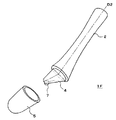
図1Aは、本発明の一実施例の塗布具1Aの斜視図、図1Bはその上面図、図1Cは図1BのA−A断面図、図1Dは図1B及び図1CのB−B断面図である。
1A is a perspective view of an
<全体構成>
この塗布具1Aは、棒状の把持部2と塗布体3を有する。塗布体3は、把持部2の一端から突出した芯部材4とこの芯部材4を覆う中空の表面部材5で形成されている。したがって、芯部材4と表面部材5との間には空隙が形成されている。
<Overall configuration>
The applicator 1 </ b> A includes a rod-
この塗布具1Aは、図1Bに示すように、上面視で左右対称に形成され、その中心線上に表面部材5の先端部と芯部材4の先端部が位置している。一方、側面視では、芯部材4と表面部材5は、それぞれ把持部2の長手方向D2に対して斜めに突出しており、後述するように、これらの突出方向が異なっている。なお、本発明において把持部2の長手方向とは、把持部2の塗布体側端部の上面視及び側面視における中心と、塗布体と反対側端部の上面視及び側面視における中心を結ぶ方向をいう。また、本発明において把持部の横断面とは把持部の長手方向に垂直な把持部の断面をいい、横断面の中心とは横断面の図心を言う。
As shown in FIG. 1B, the applicator 1 </ b> A is formed symmetrically in a top view, and the front end portion of the
塗布具1Aの大きさに関し、上面視における塗布体3の幅L1は、好ましくは10mm以上40mm以下、塗布体3の長さL2は、好ましくは10mm以上50mm以下、把持部2の長さL3は、好ましくは30mm以上150mm以下である。このように、塗布体3の大きさを、大凡親指の第1関節から先の先端部と同等又それ以上とすることにより、小鼻のまわりのように狭い空間だけでなく、頬のように広い面積にも化粧料等を塗布することが容易になる。
Regarding the size of the
<把持部>
把持部2は、その両端部に対して中央部が細径に成形されている。また、塗布体3側の端部の径は、それと反対側の端部の径よりも大きくなっている。
<Grip part>
The
<芯部材>
芯部材4は、把持部2の平坦な端面から斜めに突出する錐台形状に成形されている。図1Cに示すように、錐台形状の底面(即ち、芯部材4の基面4a)の中心4aoは、把持部2の塗布体側端面の中心2boと重なっている。
<Core member>
The
芯部材4の基面4aの好ましい形状としては、長軸Laと短軸Lbとの比を1<La/Lb≦10とすることが好ましく、1.5≦La/Lb≦5であることが更に好ましい。また、その形状は、楕円形、矩形等をあげることができる。
As a preferred shape of the
また、芯部材4の突出軸D4と直交する面で芯部材4を、その基面4aより先端部4t側で切断した場合の切断面は、芯部材4の基面4aよりもさらに扁平な形状となっており、芯部材4は全体として扁平なへら型になっている。なお、本発明において、芯部材4の外形はヘラ型に限らず、例えば、円柱状にしてもよい。
In addition, the cut surface when the
図2に示すように、把持部2と芯部材4は一体成型品となっており、これらは表面部材5よりも硬質の材料で形成される。具体的には、ポリプロピレン(PP)、ポリエチレン(PE)等のポリオレフィン樹脂、ポリエチレンテレフタレート等のポリエステル樹脂、ポリアミドABS樹脂等の硬質樹脂、ゴム、金属、セラミック、木材等をあげることができる。
As shown in FIG. 2, the
なお、把持部2と芯部材4とは、一体成型で形成されていなくてもよく、別材から形成されていてもよい。例えば、把持部2と芯部材4とを別途成形して接着剤で連結したり、インサート成形により把持部2の内部に芯部材4が挿入されたりしてもよい。
In addition, the holding
<表面部材>
表面部材5は、外形が扁平な釣鐘型をしており、後述する突出軸D5と直交する面で表面部材5を切断した場合に、外形が扁平形状となる切断面を有する。表面部材5の外形を扁平とすることにより、表面部材5で化粧料を被塗布面に塗布するにあたり、表面部材の広幅の面を使用すると、化粧料を広い塗布面に均一に塗布することが容易となり、表面部材5の幅狭の面を使用すると、狭い被塗布面に塗布することが容易となり、被塗布面の広狭に応じて被塗布面に当てる表面部材5の向きを使い分けることができる。
特に本実施例のように表面部材5の外形を釣鐘型とする場合、突出軸D5の中央部を通る切断面の外形について、長軸と短軸との比を芯部材4の長軸と短軸との比よりも小さくすることが好ましい。
<Surface member>
The
In particular, when the outer shape of the
表面部材5は弾性樹脂で形成され、好ましくは、JIS K6253にしたがって測定されるタイプAデュロメータ硬度が0〜80の軟質樹脂とし、更に好ましくは同硬度が0〜50の軟質樹脂である。なお、前記デュロメータ硬度は、JIS K6253の規定に従い、表面部材5を形成する材料で作られた厚み6mmのシート状試験片を用いて測定する。
The
また、表面部材5を形成する弾性樹脂は、当該表面部材5で塗布する化粧料等が浸透しない非多孔質のものが好ましい。
In addition, the elastic resin forming the
このような弾性樹脂としては、例えば、シリコーンゴム、エラストマー樹脂等をあげることができ、成形性の点からエラストマー樹脂であることが好ましい。エラストマー樹脂としては、スチレン系熱可塑性エラストマー、オレフィン系熱可塑性エラストマー、ウレタン系エラストマー等の熱可塑性エラストマーが好ましい。 Examples of such elastic resin include silicone rubber and elastomer resin, and elastomer resin is preferable from the viewpoint of moldability. The elastomer resin is preferably a thermoplastic elastomer such as a styrene thermoplastic elastomer, an olefin thermoplastic elastomer, or a urethane elastomer.
図示したように表面部材5を中空に形成する場合、その厚みは、例えば0.05〜3mmとすることができる。表面部材5の厚みは、部分的に変えてもよい。例えば、表面部材5の先端部5t及びその近傍の厚みを厚くし、表面部材5の縁辺5a近傍の厚みを薄くすることにより、薄い部分で塗布部全体がたわみやすくなるので、肌へのフィット感が増す。
As shown in the figure, when the
化粧料等の塗り伸ばし性を向上させるため、表面部材5の表面にシボ様の細かい凹凸を形成してもよい。このような表面凹凸を表面部材5に形成する方法としては、例えば、金型を用いて表面部材5を製造する場合に、その金型の表面に、番手が♯24程度のシボを形成しておくのが好ましい。
In order to improve the spreadability of cosmetics and the like, fine grain-like irregularities may be formed on the surface of the
<表面部材と芯部材の突出方向>
芯部材4と表面部材5の突出方向に関し、図1Dに示すように、表面部材5の縁辺5aと当接する把持部2の横断面(即ち、把持部2の長手方向D2と直交し、表面部材5の縁辺5aと当接する平面で把持部2を切断した場合の切断面)2aの中心を基点2aoとした場合に、基点2aoと表面部材5の先端部5tとを結ぶ線(即ち、表面部材5の突出軸D5)の方向が、把持部2の長手方向D2に対して傾いている。また、基点2aoと芯部材4の先端部4tとを結ぶ線(即ち、芯部材4の突出軸D4)の方向と表面部材の突出軸D5の方向とが異なっている。
<Projection direction of surface member and core member>
With respect to the protruding direction of the
ここで、表面部材5の縁辺5aとは、表面部材5の外形の把持部側端部の縁をいう。
芯部材4および表面部材5の突出方向は、芯部材4および表面部材5の把持部2側からそれぞれの先端部4t、5tに向う方向である。
Here, the
The protruding direction of the
表面部材5の先端部5tとは、基点2aoから最も距離の離れた表面部材5上の点をいい、芯部材4の先端部4tとは、基点2aoから最も距離の離れた芯部材4上の点である。
The
一方、図1Dは、把持部2の長手方向D2と平行で、表面部材5の突出軸D5を含む面で塗布具1Aを切断した場合の断面図となっている。
On the other hand, FIG. 1D is a cross-sectional view when the
肌への塗布面の接触のしやすさの点から、この断面図において、表面部材5の突出軸D5の方向と把持部2の長手方向D2とがなす角度θ1を、5°以上60°以下とすることが好ましく、特に20°以上45°以下とすることが好ましい。
In view of ease of contact of the coated surface with the skin, in this cross-sectional view, an angle θ1 formed by the direction of the protruding axis D5 of the
また、この断面図において、芯部材4の突出軸D4の方向と表面部材5の突出軸D5の方向とがなす角度θ2は、化粧料などの塗布剤を肌等の被塗布面上で伸ばしながら、被塗布面の表面凹凸に埋めこむ点から、45°以下とすることが好ましく、特に30°以下とすることが好ましい。また被塗布面上で塗布剤をこそぎ落とすことなく、塗布剤に適切な厚みを確保しながら塗布剤を被塗布面上に塗り広げる点から、角度θ2は、3°以上とすることが好ましく、特に5°以上とすることが好ましい。
In this cross-sectional view, the angle θ2 formed by the direction of the protruding axis D4 of the
本実施例の塗布具1Aでは、図1Dに示すように、芯部材4の突出軸D4の方向と把持部2の長手方向D2とのなす角θ3が、表面部材5の突出軸D5の方向と把持部2の長手方向D2とのなす角θ1よりも開いた角度になっている。そのため、芯部材4と表面部材5との間隙の大きさは、芯部材4上の点と基点2aoとを結ぶ線と把持部材2の長手方向D2とのなす角度が前記角度θ3よりも開く領域では、閉じる領域に対して小さくなっている。
In the
なお、芯部材4の先端部4tと表面部材5との距離は、好ましくは0mm以上10mm以下、より好ましくは8mm以下であり、先端部4t以外の部位における芯部材4と表面部材5との間隙は1mm以上10mm以下が好ましい。
The distance between the
図1Dにおいて、表面部材5の表面上の点と基点2aoとを結ぶ線と把持部材2の長手方向D2とのなす角度がθ1より大きい部分を塗布体3の上面側とし、小さい部分を塗布体3の背面側とした場合に、この塗布具1Aによれば、上述のように芯部材4の突出軸D4の方向と、表面部材5の突出軸D5の方向とを異ならせ、それにより、芯部材4と表面部材5との間隙の大きさが塗布体3の上面側と背面側で異なり、また、表面部材5を弾性樹脂で形成し、芯部材4をそれよりも硬質の材料で形成することにより、図3Aに示すように、肌Sに化粧料Aを塗布する場合に、まず、表面部材5の柔軟性を利用して化粧料Aの塊を徐々に潰すようにして肌Sに延ばし、次に図3Bに示すように、芯部材4の硬さも利用して化粧料を毛穴、ニキビ跡等のくぼみSpに埋め込む。これにより、図3Cに示すようにくぼみSpに化粧料Aを埋め込むと共に、その周囲にも均一に薄く化粧料Aの塗膜を形成することができ、くぼみSpを目立たなくすることができる。
In FIG. 1D, a portion where the angle between the line connecting the point on the surface of the
また、この塗布具1Aによれば、表面部材5の突出軸D5の方向が把持部2の長手方向D2に対して傾いているので、塗布体3の先端部で化粧料Aを叩き込むようにして塗布することが容易となる。その際、図4Aに示すように、まず、柔軟な表面部材5で化粧料Aを肌Sに叩き込むことにより化粧料AをくぼみSpの周りに広げ、次いで図4Bに示すように、芯部材4の硬さを利用して、くぼみSpに化粧料Aを叩き込むように化粧料Aを延ばす。これにより、表面部材5の先端を使うので、小鼻のまわり程度の狭い程度の狭い領域にあるくぼみSpにも化粧料Aを埋め込むと共に、その周囲の肌Sに化粧料Aを薄く塗布することができる。
Moreover, according to this
<変形態様>
本発明の塗布具は、種々の態様をとることができる。
例えば、図5に示した塗布具1Bは、上述の塗布具1Aにおいて、芯部材4の基面4aの中心4aoと把持部2の塗布体側端面の中心2boとがずれ、把持部2の塗布体側端面の中心2boから表面部材5の先端部5tに向かう方向D5’と、芯部材4の基面4aの中心4aoから芯部材4の先端部4tに向かう方向D4’が平行になっている。
この塗布部1Bも、表面部材5の突出軸D5の方向と芯部材4の突出軸D4の方向とが異なっており、上述の塗布具1Aと同様に使用することができる。
<Deformation mode>
The applicator of the present invention can take various forms.
For example, in the applicator 1B shown in FIG. 5, in the
The direction of the protruding axis D5 of the
図6に示した塗布具1Cは、上述の塗布具1Aにおいて、芯部材4の突出軸D4の方向と把持部材2の長手方向D2とのなす角θ3を、表面部材5の突出軸の方向D5と把持部2の長手方向D2とのなす角度θ1よりも小さくしたものである。この態様においても、芯部材4の突出軸D4の方向と表面部材5の突出軸D5の方向が異なっているので、上述の塗布具1Aと同様に使用することができる。特に、この塗布具1Cによれば、図7に示すように、肌に対して塗布体3の先端部を当てるように使用すると、肌に当たる部分で表面部材5と芯部材4との間隙が広く、表面部材5の変形量が大きくなるので、柔らかい感触を得ることができる。また、図4A〜図4Cに示したように化粧料を叩き込むようにして肌に押し広げることが容易となる。
In the
図8A及び図8Bに示した塗布具1Dは、上述の塗布具1Aにおいて、芯部材4の突出軸D4の方向と把持部材2の長手方向D2とのなす角θ3を、表面部材5の突出軸D5の方向と把持部2の長手方向D2とのなす角度θ1よりも小さくすると共に、芯部材4及び表面部材5を湾曲させたものである。
The
図9に示した塗布具1Eは、上述の塗布具1Aにおいて、芯部材4の先端領域に、芯部材4の突出軸D4の突出方向に凸部6を延設したものである。これにより、この塗布具1Eの表面部材5の先端側から化粧料を肌に叩き込むように塗布する場合に、マッサージ効果を得ることができ、また、凸部6の無い面では、上述の塗布具1Aと同様に化粧料の塗り延ばしをすることができる。
The applicator 1E shown in FIG. 9 is obtained by extending the protruding
図10に示した塗布具1Fは、上述の塗布具1Aにおいて、芯部材4の錐台形状の扁平な側面の先端部近傍に凸部7を設けたものである。これにより、この塗布具1Fの釣鐘型の表面部材5の扁平な側面側から化粧料を肌に塗布する場合に、指圧効果を得ることができる。
An applicator 1F shown in FIG. 10 is obtained by providing a convex portion 7 in the vicinity of the tip of the flat side surface of the frustum shape of the
図11A及び図11Bに示した塗布具1Gは、上述の塗布具1Aにおいて、表面部材5の把持部2側を部分的に延設し、表面部材5の縁辺5aで囲まれた面が把持部2の長手方向D2と略垂直に交わるようにしたものである。なお、この表面部材5の縁辺5aで囲まれた面は、表面部材5の縁辺5aと当接する把持部材2の横断面2aと重なっている。また、表面部材5を、芯部材4の基面4aに重なる平面P1で切断した場合に、その切断面から表面部材5の先端部5t側は上述の塗布具1Aと同様に釣鐘型に形成されている。この塗布具1Gによれば、表面部材5の把持部側を延設することにより、表面部材5が抜け落ちることを防ぐことができる。
The
本発明においては、上述の各態様において、表面部材5を中空とせず、中実としても良い。そのような塗布具は、例えば、表面部材5を肉厚にして表面部材5と芯部材4との空隙をなくしなり、表面部材5と芯部材4との間に表面部材5より柔軟な材料を充填したりして形成することができる。
In the present invention, in each of the above-described aspects, the
本発明において、表面部材5の外形は扁平な釣り鐘型に限られない。例えば、表面部材5は、その突出軸D5と直交する把持部2側の断面形状が扁平で、先端部5t側の断面形状が円であってもよく、外形全体が円柱状でもよい。
In the present invention, the outer shape of the
また、把持部2と芯部材4を別部材として形成し、組み合わせてもよい。
芯部材4の基面4aや、芯部材をその突出軸D4と直交する面で切断した面は、扁平でなくても良い。
把持部2は直棒状でもよく、弧状に湾曲していてもよい。
Further, the
The
The
本発明の塗布具で塗布するのに適した化粧料としては、ファンデーション、化粧下地、美容液等を上げることができる。また、本発明の塗布具は、軟膏等の薬剤の塗布にも有用である。 Examples of cosmetics suitable for application with the applicator of the present invention include foundations, makeup bases, and cosmetic liquids. The applicator of the present invention is also useful for application of a drug such as an ointment.
1A、1B、1C、1D、1E、1F、1G 塗布具
2 把持部
2a (表面部材の縁辺と当接する)把持部の横断面
2ao 基点(把持部の横断面の中心)
2bo 把持部の塗布体側端面の中心
3 塗布体
4 芯部材
4a 芯部材の基面
4ao 芯部材の基面の中心
4t 芯部材の先端部
5 表面部材
5a 表面部材の縁辺
5t 表面部材の先端部
6 凸部
7 凸部
A 化粧料
D2 把持部の長手方向
D4 芯部材の突出軸
D5 表面部材の突出軸
L1 塗布体の幅
L2 塗布体の長さ
L3 把持部の長さ
La 長軸
Lb 短軸
P1 平面
θ1 表面部材の突出軸の方向と把持部の長手方向とがなす角度
θ2 芯部材の突出軸の方向と表面部材の突出軸の方向とがなす角度
θ3 芯部材の突出軸の方向と把持部の長手方向とがなす角度
S 肌
Sp 毛穴等のくぼみ
1A, 1B, 1C, 1D, 1E, 1F,
2 bo Center of the end face of the application body side of the gripping part 3
Claims (7)
塗布体が、把持部の一端から突出した芯部材と、芯部材を覆う弾性樹脂で形成された表面部材とを備え、
表面部材の縁辺と当接する把持部の横断面の中心を基点とした場合に、基点と表面部材の先端部とを結ぶ線(以下、表面部材の突出軸という)の方向が把持部の長手方向に対して傾き、基点と芯部材の先端部とを結ぶ線(以下、芯部材の突出軸という)の方向と表面部材の突出軸の方向とが異なり、
把持部の長手方向と平行で、表面部材の突出軸を含む面による塗布具の切断面において、芯部材の突出軸と把持部の長手方向とのなす角度が、表面部材の突出軸と把持部の長手方向とのなす角度よりも開いている塗布具。 An applicator having a rod-shaped gripping part and an applicator,
The application body includes a core member protruding from one end of the gripping part, and a surface member formed of an elastic resin that covers the core member,
When the center of the cross section of the gripping part that contacts the edge of the surface member is the base point, the direction of the line connecting the base point and the tip of the surface member (hereinafter referred to as the protruding axis of the surface member) is the longitudinal direction of the gripping part relative inclination, the line connecting the tip of the base and the core member (hereinafter, referred to as protrusion shaft of the core member) and Ri is Do different directions of protrusion shaft direction and the surface member,
The angle formed by the protruding axis of the core member and the longitudinal direction of the gripping portion is parallel to the longitudinal direction of the gripping portion and the cutting surface of the applicator is cut by the surface including the protruding shaft of the surface member. applicator that open than the angle between the longitudinal direction of.
塗布体が、把持部の一端から突出した芯部材と、芯部材を覆う弾性樹脂で形成された表面部材とを備え、
表面部材の縁辺と当接する把持部の横断面の中心を基点とした場合に、基点と表面部材の先端部とを結ぶ線(以下、表面部材の突出軸という)の方向が把持部の長手方向に対して傾き、基点と芯部材の先端部とを結ぶ線(以下、芯部材の突出軸という)の方向と表面部材の突出軸の方向とが異なり、
把持部の長手方向と平行で、表面部材の突出軸を含む面による塗布具の切断面において、芯部材の突出軸と把持部の長手方向とのなす角度が、表面部材の突出軸と把持部の長手方向とのなす角度よりも小さい塗布具。 An applicator having a rod-shaped gripping part and an applicator,
The application body includes a core member protruding from one end of the gripping part, and a surface member formed of an elastic resin that covers the core member,
When the center of the cross section of the gripping part that contacts the edge of the surface member is the base point, the direction of the line connecting the base point and the tip of the surface member (hereinafter referred to as the protruding axis of the surface member) is the longitudinal direction of the gripping part relative inclination, the line connecting the tip of the base and the core member (hereinafter, referred to as protrusion shaft of the core member) and Ri is Do different directions of protrusion shaft direction and the surface member,
The angle formed by the protruding axis of the core member and the longitudinal direction of the gripping portion is parallel to the longitudinal direction of the gripping portion and the cutting surface of the applicator is cut by the surface including the protruding shaft of the surface member. An applicator smaller than the angle formed with the longitudinal direction .
Priority Applications (1)
| Application Number | Priority Date | Filing Date | Title |
|---|---|---|---|
| JP2014170522A JP6394179B2 (en) | 2014-08-25 | 2014-08-25 | Applicator |
Applications Claiming Priority (1)
| Application Number | Priority Date | Filing Date | Title |
|---|---|---|---|
| JP2014170522A JP6394179B2 (en) | 2014-08-25 | 2014-08-25 | Applicator |
Publications (3)
| Publication Number | Publication Date |
|---|---|
| JP2016043113A JP2016043113A (en) | 2016-04-04 |
| JP2016043113A5 JP2016043113A5 (en) | 2017-07-20 |
| JP6394179B2 true JP6394179B2 (en) | 2018-09-26 |
Family
ID=55634281
Family Applications (1)
| Application Number | Title | Priority Date | Filing Date |
|---|---|---|---|
| JP2014170522A Active JP6394179B2 (en) | 2014-08-25 | 2014-08-25 | Applicator |
Country Status (1)
| Country | Link |
|---|---|
| JP (1) | JP6394179B2 (en) |
Families Citing this family (2)
| Publication number | Priority date | Publication date | Assignee | Title |
|---|---|---|---|---|
| JP7067759B2 (en) * | 2016-08-22 | 2022-05-16 | 紀伊産業株式会社 | Makeup tools |
| KR102034969B1 (en) * | 2018-04-13 | 2019-10-21 | 이순탁 | Skincare device having a flexible massage surface |
Family Cites Families (5)
| Publication number | Priority date | Publication date | Assignee | Title |
|---|---|---|---|---|
| FR2771077B1 (en) * | 1997-11-14 | 2000-01-14 | Oreal | PACKAGING AND APPLICATION DEVICE INCLUDING A CONTAINER, AN ERGONOMIC APPLICATOR AND A SPINNING BODY |
| JP2003189928A (en) * | 2001-12-27 | 2003-07-08 | Lucky Corp:Kk | Applicator for makeup |
| JP3901612B2 (en) * | 2002-07-31 | 2007-04-04 | 株式会社志々田清心堂 | Makeup tools |
| FR2860960B1 (en) * | 2003-10-17 | 2007-03-30 | Oreal | APPLICATOR OF A PRODUCT, IN PARTICULAR COSMETIC |
| FR2886112B1 (en) * | 2005-05-24 | 2007-08-10 | Oreal | PACKAGING AND APPLICATION DEVICE |
-
2014
- 2014-08-25 JP JP2014170522A patent/JP6394179B2/en active Active
Also Published As
| Publication number | Publication date |
|---|---|
| JP2016043113A (en) | 2016-04-04 |
Similar Documents
| Publication | Publication Date | Title |
|---|---|---|
| US7861419B2 (en) | Ergonomic razor handle provided with an improved grip | |
| JP5689613B2 (en) | Massage brush and handle for massage brush | |
| JP6851303B2 (en) | Applying tool for applying cosmetic products | |
| JP4185493B2 (en) | Improved design of electric toothbrush housing | |
| JP5026417B2 (en) | Improvement of razor handle grip | |
| JP7106053B2 (en) | head brush | |
| KR20150036596A (en) | Cosmetic product applicator, device and associated method | |
| JP6394179B2 (en) | Applicator | |
| JP5458337B2 (en) | Tool handle | |
| JP5822222B2 (en) | Liquid applicator | |
| JP2014140724A (en) | Cosmetic applicator | |
| JP6394131B2 (en) | Cosmetic applicator | |
| US20180344021A1 (en) | Bottle opening brush | |
| CN114007464B (en) | Toothbrush with tooth brush | |
| TWI704883B (en) | Cosmetic applicator | |
| JP6155082B2 (en) | Cosmetic applicator | |
| JP6789075B2 (en) | toothbrush | |
| JP6605200B2 (en) | Applicator | |
| CN113194782A (en) | Tooth brush | |
| JP3218156U (en) | Makeup brush | |
| JP7634340B2 (en) | Interdental Cleaning Tools | |
| JPH119334A (en) | Nail brush | |
| JP3209926U (en) | Makeup brush | |
| JP5994633B2 (en) | Cosmetic applicator | |
| JP2008228856A (en) | Nail polishing tool |
Legal Events
| Date | Code | Title | Description |
|---|---|---|---|
| A521 | Request for written amendment filed |
Free format text: JAPANESE INTERMEDIATE CODE: A523 Effective date: 20170607 |
|
| A621 | Written request for application examination |
Free format text: JAPANESE INTERMEDIATE CODE: A621 Effective date: 20170607 |
|
| A977 | Report on retrieval |
Free format text: JAPANESE INTERMEDIATE CODE: A971007 Effective date: 20180511 |
|
| A131 | Notification of reasons for refusal |
Free format text: JAPANESE INTERMEDIATE CODE: A131 Effective date: 20180522 |
|
| A521 | Request for written amendment filed |
Free format text: JAPANESE INTERMEDIATE CODE: A523 Effective date: 20180718 |
|
| TRDD | Decision of grant or rejection written | ||
| A01 | Written decision to grant a patent or to grant a registration (utility model) |
Free format text: JAPANESE INTERMEDIATE CODE: A01 Effective date: 20180731 |
|
| A61 | First payment of annual fees (during grant procedure) |
Free format text: JAPANESE INTERMEDIATE CODE: A61 Effective date: 20180813 |
|
| R151 | Written notification of patent or utility model registration |
Ref document number: 6394179 Country of ref document: JP Free format text: JAPANESE INTERMEDIATE CODE: R151 |
|
| R250 | Receipt of annual fees |
Free format text: JAPANESE INTERMEDIATE CODE: R250 |
|
| R250 | Receipt of annual fees |
Free format text: JAPANESE INTERMEDIATE CODE: R250 |
|
| R250 | Receipt of annual fees |
Free format text: JAPANESE INTERMEDIATE CODE: R250 |
|
| R250 | Receipt of annual fees |
Free format text: JAPANESE INTERMEDIATE CODE: R250 |