JP6355780B1 - Vehicle evacuation device and vehicle evacuation method - Google Patents
Vehicle evacuation device and vehicle evacuation method Download PDFInfo
- Publication number
- JP6355780B1 JP6355780B1 JP2017043463A JP2017043463A JP6355780B1 JP 6355780 B1 JP6355780 B1 JP 6355780B1 JP 2017043463 A JP2017043463 A JP 2017043463A JP 2017043463 A JP2017043463 A JP 2017043463A JP 6355780 B1 JP6355780 B1 JP 6355780B1
- Authority
- JP
- Japan
- Prior art keywords
- vehicle
- host vehicle
- host
- evacuation
- adjacent lane
- Prior art date
- Legal status (The legal status is an assumption and is not a legal conclusion. Google has not performed a legal analysis and makes no representation as to the accuracy of the status listed.)
- Active
Links
Images


Landscapes
- Navigation (AREA)
- Control Of Driving Devices And Active Controlling Of Vehicle (AREA)
- Traffic Control Systems (AREA)
Abstract
【課題】自動運転の継続が困難になった場合に、周辺の他車両の状況に応じた自車両の退避を行う。【解決手段】退避制御部30は、自車両100の路側帯204への退避を行う際、自車両100の周辺の他車両101〜103の位置を検出する。自車両100を退避させる側の隣接車線201における自車両100の側方および後側方に他車両101が検出されると、退避制御部30は、自車両100が隣接車線201の他車両101に追い抜かれるように自車両100の速度を制御し、自車両100が隣接車線201の他車両101に追い抜かせてから、自車両100を隣接車線201へ移動させる。【選択図】図1When it is difficult to continue automatic driving, the host vehicle is retracted according to the situation of other surrounding vehicles. A retraction control unit 30 detects positions of other vehicles 101 to 103 around the host vehicle 100 when the host vehicle 100 is retracted to a roadside belt 204. When another vehicle 101 is detected on the side and rear side of the host vehicle 100 in the adjacent lane 201 on the side where the host vehicle 100 is to be retracted, the retraction control unit 30 causes the host vehicle 100 to move to the other vehicle 101 in the adjacent lane 201. The speed of the own vehicle 100 is controlled so as to be overtaken, and after the own vehicle 100 causes the other vehicle 101 to overtake the adjacent lane 201, the own vehicle 100 is moved to the adjacent lane 201. [Selection] Figure 1
Description
本発明は、車両の自動運転に関し、特に、自動運転の継続が困難になったときに車両を路肩へ退避させる技術に関する。 The present invention relates to automatic driving of a vehicle, and more particularly to a technique for retracting a vehicle to a road shoulder when it becomes difficult to continue automatic driving.
車両が周辺の障害物(例えば他車両、歩行者等)や道路の区画線などをセンサで検知することで、人による運転操作を必要とせずに、車両を自律的に走行させる自動運転技術の開発が進められている。車両の自動運転は、自車両をナビゲーション装置等で設定した経路に沿って走行させつつ、道路内の自車両の位置、周辺の道路形状、周辺の障害物などの情報に基づいて車両の進路を制御することにより実現される。 Automatic driving technology that allows a vehicle to travel autonomously without requiring a human driving operation by detecting surrounding obstacles (for example, other vehicles, pedestrians, etc.) and road markings with sensors. Development is underway. In the automatic driving of a vehicle, the vehicle travels along a route set by a navigation device or the like, and the course of the vehicle is determined based on information such as the position of the own vehicle in the road, the shape of the surrounding road, and the surrounding obstacle. It is realized by controlling.
車両の自動運転では、センサが故障したり、天候の影響によりセンサから得られる情報が制限されたりして、自動運転を継続することが困難な状況になった場合でも、安全が確保されるようにする必要がある。例えば、自動運転の継続が困難な状況になると、自車両の運転操作を自動運転の制御装置から運転者(ドライバ)へ委譲し、運転者の運転操作による走行(手動運転)に切り替えることが望ましい。しかし、自車両の運転操作を運転者へ委譲しようとする際に、運転者が正常に運転操作できない情況(例えば、運転者が覚醒状態でない情況)であれば、手動運転への切り替えを行わずに、自動運転により自車両を路肩に寄せて停止させる方法がとられる。このように自車両を自動的に適切な場所へ移動させて停止させる処理を「退避」という。 Autonomous driving of a vehicle will ensure safety even if it becomes difficult to continue autonomous driving due to sensor failure or limited information obtained from the sensor due to the influence of weather. It is necessary to. For example, when it is difficult to continue the automatic driving, it is desirable to transfer the driving operation of the host vehicle from the automatic driving control device to the driver (driver) and to switch to driving (manual driving) by the driving operation of the driver. . However, when attempting to transfer the driving operation of the host vehicle to the driver, if the driver cannot operate normally (for example, the driver is not in an awake state), the switching to manual driving is not performed. In addition, a method is adopted in which the vehicle is brought close to the road shoulder and stopped by automatic driving. The process of automatically moving the host vehicle to an appropriate place and stopping it is called “evacuation”.
例えば、下記の特許文献1では、自動運転中にセンサが故障したにも関わらず、運転者による運転操作が行われない場合に、センサが最後に取得した情報に基づいて、自車両を退避させる技術が開示されている。また、下記の特許文献2では、自車両を停止可能な停車地点を定期的に算出しながら自動運転を行い、自動運転の継続が困難になっても運転者が自動運転を解除しない場合に、事前に算出した停車地点に自車両を退避させる技術が開示されている。
For example, in
特許文献1の技術では、センサが最後に取得した情報を用いて自車両の退避制御を行うため、センサ故障時の自車両の位置と自車両を退避させる地点までの距離は短いものとなる。そのため、自車両を退避させるとき急減速させる必要が生じるため、搭乗者への負担が大きい他、後続車両に追突される恐れもある。また、特許文献2には、車両を待避させる地点まで移動させるための具体的な方法は示されていない。
In the technique of
本発明は上記のような問題を解決するためになされたものであり、自動運転の継続が困難になった場合に、周辺の他車両の状況に応じた自車両の退避を行うことが可能な車両退避装置を提供することを目的とする。 The present invention has been made to solve the above-described problems. When it becomes difficult to continue automatic driving, it is possible to evacuate the host vehicle according to the situation of other surrounding vehicles. It aims at providing a vehicle evacuation device.
本発明に係る車両退避装置は、自車両の自動運転を行うための情報を取得するセンサの認知精度低下または部分的故障を検知する異常検知部と、前記自車両周辺の障害物の情報を取得する周辺情報取得部と、前記自車両の動作状態の情報を取得する車両状態取得部と、前記自車両の運転者の状態を取得する運転者状態取得部と、前記センサの認知精度低下または部分的故障が検知され、且つ、前記自車両の運転者が運転操作を開始しない或いは正常に運転操作を行えない場合に、前記自車両を路肩へ退避させるように制御する退避制御部と、前記退避制御部が出力する前記自車両の制御情報を前記自車両の車両制御装置へ送る制御情報出力部と、を備え、前記退避制御部は、前記自車両の退避を行う際、前記周辺情報取得部が取得した情報に基づいて、前記自車両の周辺の他車両の位置を検出し、前記自車両を退避させる側の隣接車線における前記自車両の側方および後側方に他車両が検出されると、前記自車両が前記隣接車線の前記他車両に追い抜かれるように前記自車両の速度を制御し、前記隣接車線の前記他車両に前記自車両を追い抜かせてから、前記自車両を前記隣接車線へ移動させ、前記自車両が前記隣接車線の前記他車両に追い抜かれるように前記自車両の速度を制御する際、前記自車両の速度を前記隣接車線の前記他車両の速度よりも遅くし、且つ、前記隣接車線の前記他車両の位置を検出するための演算量が一定の値を超えないように、前記自車両と前記隣接車線の前記他車両との相対速度を小さく保つ。
The vehicle evacuation device according to the present invention acquires an abnormality detection unit that detects a reduction in recognition accuracy or a partial failure of a sensor that acquires information for performing automatic driving of the host vehicle, and information on obstacles around the host vehicle. A surrounding information acquisition unit, a vehicle state acquisition unit that acquires information on an operation state of the host vehicle, a driver state acquisition unit that acquires a driver state of the host vehicle, and a reduction in recognition accuracy or a part of the sensor A retraction control unit that controls the retreating of the host vehicle to a road shoulder when a malfunction is detected and the driver of the host vehicle does not start the driving operation or cannot perform the driving operation normally; A control information output unit that sends control information of the host vehicle output by the control unit to the vehicle control device of the host vehicle, and the evacuation control unit, when the host vehicle evacuates, the surrounding information acquisition unit Information obtained by Accordingly, the position of another vehicle around the own vehicle is detected, and when another vehicle is detected on the side and rear side of the own vehicle in the adjacent lane on the side where the own vehicle is to be retracted, Controlling the speed of the host vehicle to be overtaken by the other vehicle in the adjacent lane, causing the other vehicle in the adjacent lane to pass the host vehicle, and moving the host vehicle to the adjacent lane , When controlling the speed of the own vehicle so that the own vehicle is overtaken by the other vehicle in the adjacent lane, the speed of the own vehicle is made slower than the speed of the other vehicle in the adjacent lane, and the adjacent The relative speed between the host vehicle and the other vehicle in the adjacent lane is kept small so that the calculation amount for detecting the position of the other vehicle in the lane does not exceed a certain value .
本発明に係る車両退避装置によれば、自動運転の継続が困難な状況になっても手動運転への切り替えができない場合に、周辺の他車両を回避しつつ車線変更を行って自車両を退避させることができる。 According to the vehicle evacuation device of the present invention, when switching to manual operation is impossible even if it is difficult to continue automatic driving, the vehicle is evacuated by changing lanes while avoiding other surrounding vehicles. Can be made.
<実施の形態1>
図1は、実施の形態1に係る車両退避装置の構成を示すブロック図である。車両退避装置10は、車両100に搭載されるコンピュータである。以下、車両退避装置10が搭載された車両100を「自車両」といい、その他の車両を「他車両」という。
<
FIG. 1 is a block diagram illustrating a configuration of the vehicle evacuation device according to the first embodiment. The
図1のように、車両退避装置10は、ハードウェアとしてのプロセッサ20および記憶装置21を備えている。プロセッサ20は、各種の演算処理を行うIC(Integrated Circuit)であり、より具体的には、CPU(Central Processing Unit)、DSP(Digital Signal Processor)、GPU(Graphics Processing Unit)など、ソフトウェアを実行する半導体デバイスである。
As shown in FIG. 1, the
記憶装置21は、メモリ40およびストレージ41を備える。メモリ40の具体例としてはRAM(Random Access Memory)がある。ストレージ41の具体例としては、フラッシュメモリがある。また、ストレージ41は、SD(Secure Digital)メモリカード、CF(CompactFlash(登録商標))、HDD(Hard Disk Drive)、フレキシブルディスク、光ディスク、コンパクトディスク、ブルーレイ(登録商標)ディスク、DVDといった可搬記憶媒体であってもよい。
The
図1に示すように、車両退避装置10には、自車両に搭載された車両周辺センサ11、車両状態センサ12、運転者監視装置13、自動運転制御装置14、車両制御装置17およびHMI(Human Machine Interface)装置18が接続されている。
As shown in FIG. 1, the
車両周辺センサ11は、自車両100の周囲の障害物を検出する。車両周辺センサ11の例としては、自車両100に搭載されたカメラ、ソナー、ミリ波センサ、レーザセンサなどが挙げられる。車両周辺センサ11は自車両100に複数搭載されていてもよい。
The
車両状態センサ12は、自車両100の動作状態を検出する。例えば、車両状態センサ12は、自車両100の速度、加速度、旋回角、旋回角速度、ライトの点灯状態など、自車両100が搭載する各機器の状態を検知する。車両状態センサ12は自車両100に複数搭載されていてもよい。
The
運転者監視装置13は、自車両100の運転者の状態を監視し、運転者が自車両100を正常に運転操作できる状態か否かを判断する。例えば、運転者監視装置13は、車内カメラで撮影した運転者の表情や挙動、生体センサで観測した運転者の心拍や体の動きなどから、運転者の活性状態を推定することで、運転者が運転操作を正常に行えるか否かを判断する。また、運転者監視装置13は、自車両が自動運転から手動運転に切り替えられるときに、運転者が自車両100の運転操作を開始したか否かも判断することができる。運転者監視装置13は自車両100に複数搭載されていてもよい。
The
車両制御装置17は、自車両100のアクセル、ブレーキ、エンジン、ヘッドライト、警告灯といったアクチュエータを制御することで自車両100の走行を制御する電子制御装置(ECU;Electronic Control Unit)である。車両制御装置17は自車両100に複数搭載されていてもよい。
The
HMI装置18は、自車両100の運転者を含む搭乗者、自車両100周辺の歩行者、他車両およびその搭乗者など、自車両100の内側および外側の人物または機器に対して各種の情報を伝達する手段である。例えば、HMI装置18は、文字や図形などの映像、光、音、振動などを用いて情報を伝達する。HMI装置18は自車両100に複数搭載されていてもよい。
The
ここで、図示は省略しているが、自動運転制御装置14は、車両退避装置10だけでなく、車両周辺センサ11、車両状態センサ12、運転者監視装置13、車両制御装置17およびHMI装置18とも信号線を通して接続されている。自動運転制御装置14は、車両周辺センサ11、車両状態センサ12および運転者監視装置13から得られる各種の情報に基づいて、車両制御装置17およびHMI装置18を制御する。
Here, although not shown, the automatic
例えば、自動運転制御装置14は、自車両100のナビゲーション装置(不図示)等で設定された目的地までの経路、車両周辺センサ11から得られる自車両100周辺の障害物の情報、および車両状態センサ12から得られる自車両100の動作状態の情報に基づいて車両制御装置17を制御することで、自車両100を自動運転させる。具体的には、自動運転制御装置14は、自車両100が周辺の障害物を避けながら目的地までの経路に沿って走行するように、自車両100の旋回角や走行速度等の制御情報を生成する。自動運転制御装置14が生成した制御情報は車両制御装置17に入力され、それによって自車両100は自律的に走行する。自動運転制御装置14が行う自動運転の制御方法は周知の技術を利用できるため、ここでの詳細な説明は省略する。
For example, the automatic
また、自動運転制御装置14は、天候などの環境の影響や、車両周辺センサ11の部分的な故障によって、自車両100を自律的に走行させるための情報を十分に取得できなくなると、自動運転を継続することが困難と判断する。その場合、自動運転制御装置14は、自車両100を自動運転から手動運転に切り替えるために、HMI装置18を用いて運転者に自車両100の運転操作を実施するように促す通知を行う。
In addition, the automatic
このとき、運転者監視装置13は、運転者が自車両100の運転操作を正常に行える状態か否かを判断する。運転者が自車両100の運転操作を正常に行える状態でなければ、自動運転制御装置14は、自車両100を路肩へ退避させるように車両退避装置10へ指示する。また、運転者が自車両100を正常に運転操作できる状態であったとしても、実際に運転者が運転操作を開始しないようであれば、その場合も自動運転制御装置14は自車両100を退避させるように車両退避装置10へ指示する。
At this time, the
次に、車両退避装置10の詳細について説明する。図1のように、車両退避装置10は、プロセッサ20により実現される機能ブロックとして、退避制御部30、周辺情報取得部31、車両状態取得部32、運転者状態取得部33、異常検知部34、制御情報出力部37およびHMI制御部38を備えている。これらの各機能ブロックは、ハードウェアとしてのプロセッサ20が、記憶装置21のストレージ41に記憶されたプログラムを実行することによって実現される。当該プログラムは、プロセッサ20を通してメモリ40に読み込まれた後、プロセッサ20に実行される。また、各機能ブロックの処理結果を示す情報、データ、信号値および変数値などはメモリ40に記憶される(あるいは、プロセッサ20内のレジスタまたはキャッシュメモリ等に記憶されてもよい)。
Next, details of the
周辺情報取得部31は、車両周辺センサ11から自車両100の周囲の障害物の情報を取得し、その取得した情報を退避制御部30へ伝達する。車両状態取得部32は、車両状態センサ12から自車両100の動作状態の情報を取得し、その取得した情報を退避制御部30へ伝達する。運転者状態取得部33は、運転者監視装置13から運転者が運転操作を正常に行えるか否かの情報を取得し、その取得した情報を退避制御部30へ伝達する。異常検知部34は、自動運転制御装置14から自動運転の継続が困難か否かの情報を取得し、その取得した情報を退避制御部30へ伝達する。
The peripheral
退避制御部30は、異常検知部34から自動運転の継続が困難になった旨が通知されると、周辺情報取得部31、車両状態取得部32および運転者状態取得部33から送られてくる各種の情報に基づいて、自車両100を路肩へ退避させる制御(退避制御)を行う。すなわち、自車両100が路肩まで移動して停止する一連の動作を制御するための制御情報を生成する。制御情報出力部37は、退避制御部30が生成した制御情報を車両制御装置17へ伝達する。車両制御装置17が、その制御情報に基づいて自車両100の走行を制御することで、自車両100は路肩に退避する。
The
HMI制御部38は、退避制御部30からの指示に基づいて、HMI装置18を制御する。退避制御部30は、HMI制御部38を通してHMI装置18を制御することで、自車両100の内側および外側へ向けて、自車両100の退避に関連する各種の通知を行う。
The
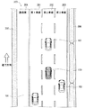
次に、図1に示した車両退避装置10の動作を説明する。図2、図3および図4は、車両退避装置10による自車両の退避を説明するための図であり、道路を走行する自車両100およびその周辺の他車両の例を示している。
Next, the operation of the
図2、図3および図4のそれぞれには、道路200を走行する自車両100と、その周辺を走行する3台の他車両101,102,103とが示されている。ここでは、道路200は、外側から第1車線201、第2車線202、第3車線203が設けられた片側3車線の道路であるものとする。道路200には、第1車線201の外側に路側帯(路肩)204が設けられている。また、路側帯204の外側にはガードレール205(または側壁)が存在し、第3車線203と対向車線(不図示)との間には中央分離帯206が存在する。
Each of FIGS. 2, 3 and 4 shows a
図2は、自車両100が、自動運転制御装置14の制御のもと、道路200の第2車線202を自動運転により走行している状態を表している。自車両100の周囲には、同一方向に走行する他車両101,102,103が存在する。他車両101は、第1車線201を走行しており、自車両100の左後側方に位置している。他車両102は、第2車線202を走行しており、自車両100の前方に位置している。他車両103は、第3車線203を走行しており、自車両100の右後側方に位置している。
FIG. 2 shows a state in which the
図2の状況において、例えば豪雨や濃霧が発生して自車両100の車両周辺センサ11の一部であるカメラを用いた物体の認知精度が低下したり、或いは、車両周辺センサ11が部分的に故障したりして、十分な車両周辺状況が取得できなくなったと仮定する。
In the situation of FIG. 2, for example, heavy rain or heavy fog occurs, and the recognition accuracy of an object using a camera that is a part of the
その場合、自動運転制御装置14は、自動運転を継続することが困難と判断し、HMI装置18を用いて、自車両100の運転者へ運転操作を行うように促す通知を行う。この通知としては、例えば、表示装置や警告ランプによる警告表示による通知、音声メッセージによる通知、シートの振動による通知、シートベルトの締め上げによる通知など、運転者が認識可能なものであれば任意のものでよい。また、自動運転制御装置14は、運転者監視装置13を用いて、運転者が運転操作を正常に行える状態か否かを確認する。このとき運転者が運転操作を正常に行える状態であれば、自動運転制御装置14は自動運転を中断して、自車両100の運転操作を運転者へ委譲する。
In that case, the automatic
しかし、運転者が運転操作を正常に行えない状態である場合、或いは、運転操作を開始しない場合には、自動運転制御装置14は、車両退避装置10に対して自車両100の退避制御を行うように指示する。自動運転制御装置14からの指示に応じて車両退避装置10が自車両100の退避制御を開始すると、自動運転制御装置14は、車両制御装置17への制御情報の送信を取りやめ、その後は、車両退避装置10が主導的に車両制御装置17へ制御情報を送るようになる。
However, when the driver cannot perform the driving operation normally or when the driving operation is not started, the automatic
車両退避装置10は、自車両100の退避制御を開始する際、HMI装置18を介して運転者に退避制御を開始する旨を通知するとともに、周辺に存在する他車両101,102,103に対しても、自車両100の退避制御を開始する旨(つまり、自車両100の自動運転に異常が生じている旨)を通知する。自車両100の外側への通知としては、例えば車両制御装置17を用いて自車両100のランプ(例えばハザードランプ等)を点滅させる方法や、警笛を鳴らす方法などが考えられる。或いは、自車両100の外側から認識できるHMI装置18を用いて視覚的な通知を行ってもよい。また、自車両100を小刻みに左右に蛇行させる通知の方法も考えられる。
When the
その後、車両退避装置10は、車両周辺センサ11から取得した有効な検知情報を用い、自車両100周辺の障害物の有無を確認する。さらに、車両退避装置10は車両制御装置17に対し、自車両100を減速させるための制御情報を送る。自車両100を減速させる際、車両退避装置10は、自車両100の速度が法定速度以下にならないようにするほか、後続車両との車間距離が急激に短くならないように、緩やかに減速させる。例えば自車両100に惰性走行を行わせることで、自車両100の速度を緩やかに下げてもよい。
Thereafter, the
ここで、一般的な高速道路では、最高速度は100km/h、最低速度は50km/hと規定されている。よって、自車両100を最低速度で走行させていれば、最高速度で走行する他車両に追い抜かれる場合と、静止物体とすれ違う場合とで、共に相対速度は50km/hという関係となる。つまり、自車両100と周辺の物体との相対速度は、最大でも50km/h程度となる。
Here, in a general highway, the maximum speed is defined as 100 km / h and the minimum speed is defined as 50 km / h. Therefore, if the
また、車両周辺センサ11を用いて、同一の物体を2回から3回連続して検知することができれば、その物体が移動しているか否かを判断できる。また、物体が移動していることを正確に検知するためには、自車両100と物体との相対位置における検知タイミングごとの変化量が、1mから2m程度以下であることが好ましい。自車両100と物体との相対速度が50km/h(=13.898m/s)であるとすると、自車両100と物体との相対位置の検知タイミングごとの変化量を1mから2m程度とするためには、車両周辺センサ11が100ms程度の周期で物体を検知する能力を持っていればよい。また、自車両100と物体との相対速度が小さいほど、車両周辺センサ11の検知周期は長くてもよい。
Further, if the same object can be detected continuously two to three times using the
図3は、自車両100を減速させた後の、自車両100および他車両101,102,103の状態を示している。図3では、自車両100が減速したことにより、第1車線201の他車両101と、第3車線203の他車両103とが、自車両100を追い抜いている。
FIG. 3 shows the state of the
車両退避装置10は、車両周辺センサ11から得られる利用可能な情報を用いて、自車両100を退避させる側(路側帯204側)の隣接車線である第1車線201を走行する他車両101の位置(自車両100との相対位置)を検出する。また、車両退避装置10は、他車両101の位置の変化を観測することで、自車両100が他車両101に追い抜かれたかどうかを判断することができる。以下、自車両100を退避させる側の方向を「退避側」ということもある。
The
図5〜図7は、車両周辺センサ11を用いて、自車両100が他車両101に追い抜かれたことを検知する様子を表している。図5〜図7において、自車両100を囲む点線の扇形のそれぞれは、車両周辺センサ11の検知範囲の例を示している。他車両101の車両周辺センサ11の検知範囲内に位置すれば、車両退避装置10によってその存在が検知されることになる。
5 to 7 show how the
図5の状態では、車両退避装置10は、他車両101が自車両100の左後側方に存在することを認識する。自車両100が減速して図6の状態になると、車両退避装置10は、他車両101が自車両100の左側方に移動したことを認識する。さらに、図7の状態になると、車両退避装置10は、他車両101が自車両100の左前側方に移動したこと、すなわち、自車両100が他車両101に追い抜かれたことを認識する。
In the state of FIG. 5, the
自車両100が他車両101に追い抜かれると、車両退避装置10は、車両周辺センサ11を用いて、第1車線201における自車両100の側方および後側方に、自車両100が移動できる空間があるかどうかを確認する。自車両100が移動できる空間があることが確認できれば、車両退避装置10は、自車両100を第1車線201に移動させるための制御情報を車両制御装置17へ送り、自車両100に第1車線201への車線変更を行わせる。
When the
図8〜図10は、車両退避装置10が車線変更を行う様子を表している。自車両100が他車両101に追い抜かれて図8のような状態になると、車両退避装置10は、矢印で示す方向へ自車両100を移動させるように、車両制御装置17へ制御情報を送る。まず、車両退避装置10は、図9のように、他車両101が自車両100の左前側方に位置することになるように自車両100を移動させる。次に、図10のように、他車両101が自車両100の前方に位置することになるように自車両100を移動させる。つまり、自車両100を他車両101の後方に回り込ませる。
8 to 10 show how the
その結果、図4のように、自車両100は、第2車線202から退避側の隣接車線である第1車線201へと移動することになる。この車線変更のための一連の動作では、車両退避装置10が、他車両101が自車両100の車両周辺センサ11の検知範囲に入り続けるように自車両100と他車両101との相対速度を制御して、自車両100をその他車両の後方に回り込み追従するようにするとよい。
As a result, as shown in FIG. 4, the
車両退避装置10は、自車両100が第1車線201へ移動すると、車両制御装置17を用いて自車両100を更に減速させる。また、車両退避装置10は、車両周辺センサ11を用いて路側帯204に自車両100を停止可能な空間があるかを確認しつつ、車両制御装置17を用いて自車両100の左側(退避側)の方向指示器を点灯させる。そして、路側帯204に十分な空間があることを確認できれば、車両制御装置17を用いて自車両100を路側帯204へ移動させる。そして、車両退避装置10は、車両周辺センサ11からの情報に基づき、自車両100がガードレール205に衝突しないようにガードレール205からの距離を確保しつつ、自車両100を停止させる。これにより、自車両100の退避が完了する。
When the
自車両100を退避させる際の減速の制御および車線変更の制御は、車両退避装置10が車両状態センサ12を用いて自車両100の速度や旋回速度を観測しながら、自車両100の挙動が不安定にならないように行われる。
In the deceleration control and the lane change control when the
また、車両周辺センサ11から取得した情報を用いて他車両の位置を検出するための演算量は、その他車両と自車両100との相対速度に依存し、相対速度が小さいほど演算量を削減できる。そこで、退避制御部30は、自車両100の速度を制御する際、退避側の隣接車線を走行する他車両の位置を検出するための演算量が一定の値を超えないように、当該他車両と自車両100との相対速度を小さく保つようにする。このように、他車両の位置を検出するための退避制御部30の演算量を抑制することで、プロセッサ20として安価なECUを用いることができる。
Further, the amount of calculation for detecting the position of another vehicle using information acquired from the
なお、自車両100の退避側の隣接車線において、自車両100の側方および後側方に他車両が検出されなければ、道路交通法で規定される一定時間だけ方向指示器を点灯させた後、車線変更を実施すればよい。
In the adjacent lane on the evacuation side of the
また、車両退避装置10が自車両100を退避させている途中で、運転者が運転操作を開始したり、運転者監視装置13により運転者が運転操作を正常に行える状態になったことが検知されたりした場合には、その時点で自車両100の退避を中止し、自車両100の運転操作を運転者へ委譲すればよい。
Further, while the
上の説明では、自車両100を第2車線202から路側帯204へ退避させる例を示したが、例えば自車両100が第3車線203を走行していた場合など、自車両100の走行車線と路側帯204との間に複数の車線が存在する場合には、上記と同様の手順で複数回の車線変更を繰り返せばよい。
In the above description, the example in which the
次に、図11および図12のフローチャートを参照しつつ、車両退避装置10の動作の詳細を説明する。
Next, details of the operation of the
車両退避装置10は、自動運転制御装置14による自車両100の自動運転が開始されると、図11の処理を開始する。図11の処理では、車両退避装置10の異常検知部34が、自動運転制御装置14から、自車両100の自動運転の情況、具体的には、自動運転の継続が困難かどうかの判断結果を取得する(ステップS101)。自車両100の自動運転の継続が困難な情況でなければ(ステップS102でNO)、ステップS101が繰り返し行われる。
The
自車両100の自動運転の継続が困難な情況になると(ステップS102でYES)、退避制御部30が、運転者監視装置13を用いて運転者の状態を監視する運転者監視処理を起動する(ステップS103)。より具体的には、運転者監視処理は、運転者の状態を監視して、運転者が運転操作を正常に行える情況になった場合、また、運転者が運転操作を開始したか場合に、自車両100の退避を中断して、自車両100の運転操作を運転者に委譲するための処理である。この運転者監視処理は、図11の処理に平行して実行される。運転者監視処理は図12のフローチャートで表されるが、その説明は後述する。
When it becomes difficult to continue the automatic driving of the host vehicle 100 (YES in step S102), the
運転者監視処理を起動した後、退避制御部30は、HMI制御部38を介してHMI装置18を制御し、運転者に対して自車両100の退避制御が実施される旨を通知する(ステップS104)。さらに、退避制御部30は、自車両100の外側の他車両や歩行者等に対しても、自車両100の退避制御が行われる旨(つまり、自動運転に異常が生じている旨)を通知する(ステップS105)。
After starting the driver monitoring process, the
その後、退避制御部30は、制御情報出力部37を介して車両制御装置17を制御し、自車両100を減速させる(ステップS106)。その際、退避制御部30は、後方車両が自車両100へ追突しないように、車両周辺センサ11で後方車両との車間距離を測定しながら自車両100を減速させる。
Thereafter, the
次に、退避制御部30は、周辺情報取得部31が取得した車両周辺センサ11からの情報に基づいて、自車両100の周辺の障害物の有無を検知する(ステップS107)。このとき、天候等の影響で車両周辺センサ11の検出精度が低下していたり、車両周辺センサ11が部分的に故障していたりすることが想定されるが、この処理は、悪天候等の条件下でも障害物を検知可能な、ソナー、レーダーなど、現時点で利用可能なセンサを組み合わせて行われる。
Next, the
その結果、自車両100を退避側隣接車線における自車両100の側方および後側方に他車両が存在した場合(ステップS108でYES)、図5〜図7を用いて説明したように、自車両100が他車両に追い抜かれるのを待つ(ステップS109)。
As a result, when there is another vehicle on the side and rear side of the
自車両100が他車両に追い抜かれると、退避制御部30は、退避側隣接車線に自車両100を移動可能な空間があるかを確認する(ステップS110)。なお、退避側隣接車線に他車両が存在しなかった場合には(ステップS108でNO)、ステップS109をスキップしてステップS110が実行される。
When the
退避側隣接車線に自車両100を移動可能な空間がなければ(ステップS110でNO)、ステップS107へ戻る。一方、退避側隣接車線に自車両100を移動可能な空間があれば(ステップS110でYES)、退避制御部30は、自車両100が退避側隣接車線へ車線変更することを周囲に通知するために、制御情報出力部37を介して車両制御装置17を制御し、自車両100の退避側の方向指示器をオンにする(ステップS111)。
If there is no space in the evacuation side adjacent lane where the
そして、図8〜図10を用いて説明したように、自車両100を退避側隣接車線へ移動させる(ステップS112)。このとき、車両退避装置10は、車両状態取得部32が車両状態センサ12から取得した自車両100の動作状態を参照し、自車両100が車線の幅(一般的には3.5メートル程度)に応じた距離だけ横方向に移動するように制御する。自車両100の車線変更が完了すると、車両退避装置10は、制御情報出力部37を介して車両制御装置17を制御し、自車両100の方向指示器をオフにする(ステップS113)。
And as demonstrated using FIGS. 8-10, the
退避制御部30は、自車両100の車線変更を行った結果、自車両100が路側帯204に移動したかどうかを判定する(ステップS114)。自車両100がまだ路側帯204に達していなければ(ステップS114でNO)、ステップS107へ戻り、再び車線変更が実行される。
The
自車両100が路側帯204に移動したかどうかの判定は、次のような方法で行うことができる。例えば、図2に示した道路200において、車両周辺センサ11により自車両100の退避側の側方に障害物が定常的に検知されれば、その障害物はガードレール205であると推定し、自車両100が路側帯204に移動したと判断することができる。逆に、自車両100の退避側の側方に障害物が無い状態が定常的に続けば、自車両100と路側帯204との間にまだ走行車線が存在すると判断することができる。
The determination as to whether the
また、路側帯は走行車線に比べて路面状態が悪いことが多いため、例えば、車両状態センサ12により縦方向の振動が継続して検出される場合に、自車両100が路側帯を走行していると判断してもよい。
In addition, since the road surface condition of the roadside band is often worse than that of the traveling lane, for example, when the
自車両100が路側帯に移動したと判断されると(ステップS114でYES)、退避制御部30は、周辺情報取得部31が車両周辺センサ11から取得する情報に基づき、自車両100の周辺の障害物を検知する(ステップS115)。そして、退避制御部30は、制御情報出力部37を通して車両制御装置17を制御することで、自車両100をガードレール205に寄せるように操舵しつつ、自車両100の減速および停止を行う(ステップS116)。その結果、自車両100の路側帯への退避が完了する。
When it is determined that the
ここで、図11のフローのステップS103で起動される運転者監視処理について説明する。図12は、運転者監視処理のフローチャートである。 Here, the driver monitoring process started in step S103 of the flow of FIG. 11 will be described. FIG. 12 is a flowchart of the driver monitoring process.
運転者監視処理では、運転者状態取得部33が運転者監視装置13から運転者の状態の情報を取得する(ステップS201)。次に、退避制御部30は、運転者監視装置13から取得した情報に基づいて、運転者が自車両100の運転操作を正常に行える状態か否かを確認する(ステップS202)。運転者が自車両100の運転操作を正常に行える状態ではない場合は(ステップS202でNO)、ステップS201に戻る。
In the driver monitoring process, the driver
運転者が運転操作を正常に行える状態である場合、運転者が運転操作を開始したかどうかを判定する(ステップS203)。運転者が運転操作を開始しなければ(ステップS203でNO)、ステップS201へ戻る。先に述べたように、図12の処理は図11の処理に平行して実行され、上記のステップS201〜S203が繰り返し実行されている間は図11の処理は続行される。 If the driver can perform the driving operation normally, it is determined whether the driver has started the driving operation (step S203). If the driver does not start the driving operation (NO in step S203), the process returns to step S201. As described above, the process of FIG. 12 is executed in parallel with the process of FIG. 11, and the process of FIG. 11 is continued while the above steps S201 to S203 are repeatedly executed.
運転者が運転操作を開始した場合には(ステップS203でYES)、退避制御部30は、自車両100の運転操作を運転者に委譲するために、図11の処理の処理を中止する(ステップS204)。それに伴い、退避制御部30は、図11のステップS104で開始した運転者への通知を解除し(ステップS205)、また、図11のステップS105で開始した自車両の外側への通知も解除する(ステップS206)。その後、退避制御部30の処理は終了する。
When the driver starts the driving operation (YES in step S203), the
以上説明したように、実施の形態1に係る車両退避装置10によれば、自車両100の退避側の側方または後側方に他車両を検出されると、自車両100がその他車両に追い抜かれるのを待ってから、車線変更を行う制御を行う。従って、自動運転制御装置14が自動運転を継続することが困難になった情況においても、適切に自車両100を路肩(路側帯)へ退避させることができる。
As described above, according to the
また、上の説明では、車両退避装置10は、車両周辺センサ11の不具合が生じたときに自車両100を退避させる手段として用いられたが、自動運転制御装置14が故障したときに自車両100を退避させる手段としても用いることができる。
In the above description, the
<実施の形態2>
実施の形態1では、自車両100の車線変更を行う際に(図11のステップS112)、自車両100の側方への移動量を、車線幅を基準にして制御したが、実施の形態2ではその制御を地図上の自車両100の位置に基づいて行う。
<Embodiment 2>
In the first embodiment, when the lane of the
図13は、実施の形態2に係る車両退避装置10の構成を示すブロック図である。図13の車両退避装置10は、図1の構成に対し、自車両100が搭載する自車位置取得装置15から情報を取得する自車位置取得部35を追加した構成となっている。
FIG. 13 is a block diagram showing a configuration of the
自車位置取得装置15は、GPS(Global Positioning System)受信機(不図示)等が取得した自車両100の位置の情報と、自車両100の周辺の地図情報とから、地図上の自車両100の位置を算出する。ここで用いられる地図情報は、道路の形状だけでなく、道路内の各車線や路肩(路側帯)の位置などの情報を含む、高精度な地図である。高精度な地図情報は、例えば、内閣府が主導する「戦略的イノベーション創造プログラム(SIP)」での整備が進められているものがあり、高精度な自車両100の位置を取得できれば、センチメートルオーダーで道路の形状およびその道路上における自車の位置を求めることができる。
The own vehicle
なお、自車位置取得装置15が取得する自車両100の位置の情報および自車両100の周辺の地図情報は、例えば、自車両100が搭載するナビゲーション装置から取得してもよい。また、それらの情報が自動運転制御装置14による自動運転制御にも用いられている場合は、自動運転制御装置14から取得してもよい。
Note that the position information of the
自車位置取得部35は、自車位置取得装置15から、自車両100が走行中の道路の形状、各車線や路肩(路側帯)の位置の情報と、当該道路内の自車両100の位置の情報とを取得し、それらの情報を退避制御部30へ送る。実施の形態2では、退避制御部30は、それらの情報から、自車両100が走行中の道路の各車線および路肩の位置を判断することができる。
The own vehicle
実施の形態2に係る車両退避装置10の動作は、基本的に図11および図12で説明した処理と同じである。ただし、図11のステップS112において自車両100の車線変更を行う際、自車位置取得装置15から取得した情報に基づいて、自車両100が走行中の車線と、退避側隣接車線の中心位置を求め、それらを基準にして、自車両100の側方への移動量を制御する。また、ステップS114における路側帯へ移動したかどうかの判定は、自車位置取得装置15から取得した情報に基づいて、自車両100が走行車線の位置よりも外側に移動したかどうかを判断することで行う。
The operation of the
<実施の形態3>
図14は、実施の形態3に係る車両退避装置10の構成を示すブロック図である。図13の車両退避装置10は、図13の構成に対し、自車両100が搭載する通信装置16を用いて通信を行う通信処理部36を追加した構成となっている。
<Embodiment 3>
FIG. 14 is a block diagram illustrating a configuration of the
通信装置16は、他車両や路上の通信設備との通信により情報を送受信する機能を有する。例えば、通信装置16が近隣の他車両との通信(車車間通信)を行い、各車両が自身の位置を通知し合い、互いの位置を認識し合うことによって、車両同士の衝突を避けることができる。また、通信装置16は、路上の通信設備から、渋滞情報、工事情報、事故情報、道路規制情報などの交通情報の取得することもできる。通信装置16は、専用の通信機でもよいし、例えば携帯電話やスマートフォンなどの汎用の通信機でもよい。
The
実施の形態2に係る車両退避装置10の動作は、基本的に図11および図12で説明した処理と同じであるが、通信処理部36は、通信装置16を用いて、退避制御部30が行う退避制御に利用できる各種の情報を送受信する。例えば、図11のステップS105において、自車両100の退避制御が行われる旨を他車両へ通知する際、その通知を、通信装置16を用いた車車間通信により行うことができる。また、ステップS107〜S110,S112の各処理では、自車両100周辺の他車両の位置を検出する必要があるが、通信装置16を用いた車車間通信により取得した各他車両の位置の情報に基づいて、それらの位置を検出してもよい。
The operation of the
図1、図13および図14では、プロセッサ20を1つのブロックで示したが、プロセッサ20は複数のプロセッサから構成されていてもよい。すなわち、複数のプロセッサが連携して動作して、プロセッサ20の各機能を実現してもよい。同様に、記憶装置21も複数の記憶装置から構成されていてもよい。すなわち、車両退避装置10は、プロセッサとメモリをそれぞれ備える複数の装置から構成されていてもよい。
In FIG. 1, FIG. 13 and FIG. 14, the
なお、本発明は、その発明の範囲内において、各実施の形態を自由に組み合わせたり、各実施の形態を適宜、変形、省略することが可能である。 It should be noted that the present invention can be freely combined with each other within the scope of the invention, and each embodiment can be appropriately modified or omitted.
10 車両退避装置、11 車両周辺センサ、12 車両状態センサ、13 運転者監視装置、14 自動運転制御装置、15 自車位置取得装置、16 通信装置、17 車両制御装置、18 HMI装置、20 プロセッサ、21 記憶装置、30 退避制御部、31 周辺情報取得部、32 車両状態取得部、33 運転者状態取得部、34 異常検知部、35 自車位置取得部、36 通信処理部、37 制御情報出力部、38 HMI制御部、40 メモリ、41 ストレージ、100 自車両、101〜103 他車両、102 他車両、103 他車両、200 道路、201 第1車線、202 第2車線、203 第3車線、204 路側帯、205 ガードレール、206 中央分離帯。
DESCRIPTION OF
Claims (12)
前記自車両周辺の障害物の情報を取得する周辺情報取得部と、
前記自車両の動作状態の情報を取得する車両状態取得部と、
前記自車両の運転者の状態を取得する運転者状態取得部と、
前記センサの認知精度低下または部分的故障が検知され、且つ、前記自車両の運転者が運転操作を開始しない或いは正常に運転操作を行えない場合に、前記自車両を路肩へ退避させるように制御する退避制御部と、
前記退避制御部が出力する前記自車両の制御情報を前記自車両の車両制御装置へ送る制御情報出力部と、
を備え、
前記退避制御部は、前記自車両の退避を行う際、
前記周辺情報取得部が取得した情報に基づいて、前記自車両の周辺の他車両の位置を検出し、
前記自車両を退避させる側の隣接車線における前記自車両の側方および後側方に他車両が検出されると、前記自車両が前記隣接車線の前記他車両に追い抜かれるように前記自車両の速度を制御し、
前記隣接車線の前記他車両に前記自車両を追い抜かせてから、前記自車両を前記隣接車線へ移動させ、
前記自車両が前記隣接車線の前記他車両に追い抜かれるように前記自車両の速度を制御する際、前記自車両の速度を前記隣接車線の前記他車両の速度よりも遅くし、且つ、前記隣接車線の前記他車両の位置を検出するための演算量が一定の値を超えないように、前記自車両と前記隣接車線の前記他車両との相対速度を小さく保つ、
車両退避装置。 An anomaly detector that detects a reduction in recognition accuracy or a partial failure of a sensor that acquires information for performing automatic driving of the host vehicle;
A peripheral information acquisition unit that acquires information on obstacles around the host vehicle;
A vehicle state acquisition unit for acquiring information on the operation state of the host vehicle;
A driver state acquisition unit for acquiring the state of the driver of the host vehicle;
Control is performed so that the host vehicle is retracted to a road shoulder when a reduction in recognition accuracy or a partial failure of the sensor is detected and the driver of the host vehicle does not start driving operation or cannot perform driving operation normally. An evacuation control unit,
A control information output unit for sending control information of the host vehicle output by the evacuation control unit to a vehicle control device of the host vehicle;
With
When the retreat control unit retreats the host vehicle,
Based on the information acquired by the peripheral information acquisition unit, detects the position of other vehicles around the host vehicle,
When another vehicle is detected on the side and rear side of the own vehicle in the adjacent lane on the side where the own vehicle is retracted, the own vehicle is overtaken by the other vehicle in the adjacent lane. Control the speed,
After allowing the other vehicle in the adjacent lane to pass the host vehicle, the host vehicle is moved to the adjacent lane ,
When controlling the speed of the own vehicle so that the own vehicle is overtaken by the other vehicle in the adjacent lane, the speed of the own vehicle is made slower than the speed of the other vehicle in the adjacent lane, and the adjacent Keeping the relative speed between the host vehicle and the other vehicle in the adjacent lane small so that the amount of calculation for detecting the position of the other vehicle in the lane does not exceed a certain value,
Vehicle evacuation device.
請求項1に記載の車両退避装置。 An HMI control unit for notifying that the host vehicle is retracted toward the inside and the outside of the host vehicle when the host vehicle is retracted;
The vehicle evacuation device according to claim 1.
請求項1または請求項2に記載の車両退避装置。 The retraction control unit controls the own vehicle so that the other vehicle in the adjacent lane is within a detection range of a vehicle periphery sensor of the own vehicle when moving the own vehicle to the adjacent lane. Moving the vehicle behind the other vehicle in the adjacent lane,
The vehicle evacuation device according to claim 1 or 2 .
請求項1から請求項3のいずれか一項に記載の車両退避装置。 If the other vehicle is not detected on the side and rear side of the own vehicle in the adjacent lane on the side where the own vehicle is to be withdrawn, the retraction control unit turns on the direction indicator of the own vehicle for a certain period of time. After, the host vehicle is moved to the adjacent lane,
The vehicle evacuation device according to any one of claims 1 to 3 .
前記退避制御部は、前記自車位置取得部が取得した情報に基づいて、前記自車両が走行中の道路の各車線および前記路肩の位置を判断する、
請求項1から請求項4のいずれか一項に記載の車両退避装置。 A vehicle position acquisition unit that acquires information of the position of the vehicle on a map;
The evacuation control unit determines the position of each lane of the road on which the host vehicle is traveling and the position of the road shoulder based on the information acquired by the host vehicle position acquisition unit.
The vehicle evacuation device according to any one of claims 1 to 4 .
前記退避制御部は、前記通信処理部が取得した他車両の位置の情報を、前記自車両の周辺の他車両の位置の検出に利用する、
請求項1から請求項5のいずれか一項に記載の車両退避装置。 A communication processing unit for acquiring information on the position of the other vehicle by communication with the other vehicle;
The evacuation control unit uses the information on the position of the other vehicle acquired by the communication processing unit to detect the position of the other vehicle around the host vehicle.
The vehicle evacuation device according to any one of claims 1 to 5 .
前記車両退避装置の異常検知部が、自車両の自動運転を行うための情報を取得するセンサの認知精度低下または部分的故障を検知する処理と、
前記車両退避装置の運転者状態取得部が、前記自車両の運転者の状態を取得する処理と、
前記センサの認知精度低下または部分的故障が検知され、且つ、前記自車両の運転者が運転操作を開始しない或いは正常に運転操作を行えない場合に、前記車両退避装置の退避制御部が、前記自車両を路肩へ退避させるように制御する処理と、
を含み、
前記自車両の退避させるように制御する処理において、
前記退避制御部は、
前記自車両周辺の障害物の情報に基づいて、前記自車両の周辺の他車両の位置を検出し、
前記自車両を退避させる側の隣接車線における前記自車両の側方および後側方に他車両が検出されると、前記自車両が前記隣接車線の前記他車両に追い抜かれるように前記自車両の速度を制御し、
前記隣接車線の前記他車両に前記自車両を追い抜かせてから、前記自車両を前記隣接車線へ移動させ、
前記自車両が前記隣接車線の前記他車両に追い抜かれるように前記自車両の速度を制御する際、前記自車両の速度を前記隣接車線の前記他車両の速度よりも遅くし、且つ、前記隣接車線の前記他車両の位置を検出するための演算量が一定の値を超えないように、前記自車両と前記隣接車線の前記他車両との相対速度を小さく保つ、
車両退避方法。 A vehicle evacuation method in a vehicle evacuation device,
An abnormality detection unit of the vehicle evacuation device detects a decrease in recognition accuracy or a partial failure of a sensor that acquires information for performing automatic driving of the host vehicle, and
The driver state acquisition unit of the vehicle evacuation device acquires the driver's state of the host vehicle,
When a reduction in recognition accuracy or a partial failure of the sensor is detected , and the driver of the host vehicle does not start the driving operation or cannot perform the driving operation normally, the evacuation control unit of the vehicle evacuation device includes the A process for controlling the vehicle to retreat to the shoulder,
Including
In the process of controlling the vehicle to retreat,
The evacuation control unit
Based on information on obstacles around the host vehicle, the position of other vehicles around the host vehicle is detected,
When another vehicle is detected on the side and rear side of the own vehicle in the adjacent lane on the side where the own vehicle is retracted, the own vehicle is overtaken by the other vehicle in the adjacent lane. Control the speed,
After allowing the other vehicle in the adjacent lane to pass the host vehicle, the host vehicle is moved to the adjacent lane ,
When controlling the speed of the own vehicle so that the own vehicle is overtaken by the other vehicle in the adjacent lane, the speed of the own vehicle is made slower than the speed of the other vehicle in the adjacent lane, and the adjacent Keeping the relative speed between the host vehicle and the other vehicle in the adjacent lane small so that the amount of calculation for detecting the position of the other vehicle in the lane does not exceed a certain value,
Vehicle evacuation method.
請求項7に記載の車両退避方法。 When the host vehicle is retracted, the HMI control unit of the vehicle retractor further includes a process of notifying that the host vehicle is retracted toward the inside and the outside of the host vehicle.
The vehicle evacuation method according to claim 7 .
請求項7または請求項8に記載の車両退避方法。 The retraction control unit controls the own vehicle so that the other vehicle in the adjacent lane is within a detection range of a vehicle periphery sensor of the own vehicle when moving the own vehicle to the adjacent lane. Moving the vehicle behind the other vehicle in the adjacent lane,
The vehicle evacuation method according to claim 7 or 8 .
請求項7から請求項9のいずれか一項に記載の車両退避方法。 If the other vehicle is not detected on the side and rear side of the own vehicle in the adjacent lane on the side where the own vehicle is to be withdrawn, the retraction control unit turns on the direction indicator of the own vehicle for a certain period of time. After, the host vehicle is moved to the adjacent lane,
The vehicle evacuation method according to any one of claims 7 to 9 .
請求項7から請求項10のいずれか一項に記載の車両退避方法。 The evacuation control unit determines the position of each lane of the road on which the host vehicle is traveling and the position of the road shoulder based on information on the position of the host vehicle on a map.
The vehicle evacuation method according to any one of claims 7 to 10 .
請求項7から請求項11のいずれか一項に記載の車両退避方法。 The evacuation control unit uses the position information of the other vehicle acquired by communication with the other vehicle to detect the position of the other vehicle around the own vehicle.
The vehicle evacuation method according to any one of claims 7 to 11 .
Priority Applications (1)
| Application Number | Priority Date | Filing Date | Title |
|---|---|---|---|
| JP2017043463A JP6355780B1 (en) | 2017-03-08 | 2017-03-08 | Vehicle evacuation device and vehicle evacuation method |
Applications Claiming Priority (1)
| Application Number | Priority Date | Filing Date | Title |
|---|---|---|---|
| JP2017043463A JP6355780B1 (en) | 2017-03-08 | 2017-03-08 | Vehicle evacuation device and vehicle evacuation method |
Publications (2)
| Publication Number | Publication Date |
|---|---|
| JP6355780B1 true JP6355780B1 (en) | 2018-07-11 |
| JP2018144720A JP2018144720A (en) | 2018-09-20 |
Family
ID=62843705
Family Applications (1)
| Application Number | Title | Priority Date | Filing Date |
|---|---|---|---|
| JP2017043463A Active JP6355780B1 (en) | 2017-03-08 | 2017-03-08 | Vehicle evacuation device and vehicle evacuation method |
Country Status (1)
| Country | Link |
|---|---|
| JP (1) | JP6355780B1 (en) |
Cited By (8)
| Publication number | Priority date | Publication date | Assignee | Title |
|---|---|---|---|---|
| WO2019026469A1 (en) * | 2017-07-31 | 2019-02-07 | 日立オートモティブシステムズ株式会社 | Vehicle control apparatus, vehicle control method, and vehicle control program |
| JP2020164066A (en) * | 2019-03-29 | 2020-10-08 | 本田技研工業株式会社 | Vehicle control system |
| CN111746532A (en) * | 2019-03-29 | 2020-10-09 | 本田技研工业株式会社 | vehicle control system |
| CN113195330A (en) * | 2018-12-19 | 2021-07-30 | 日立安斯泰莫株式会社 | Electronic control device and in-vehicle system |
| JP2022009840A (en) * | 2018-01-17 | 2022-01-14 | トヨタ自動車株式会社 | Vehicle travel support system and vehicle travel support method |
| JP2022104120A (en) * | 2020-12-28 | 2022-07-08 | 本田技研工業株式会社 | Vehicle control system and road shoulder approach determination method |
| KR102503572B1 (en) * | 2018-12-13 | 2023-02-24 | 웨이모 엘엘씨 | Automated Performance Tests for Autonomous Vehicles |
| JP7674553B2 (en) | 2019-08-28 | 2025-05-09 | パイオニア株式会社 | Information processing device, control method, program, and storage medium |
Families Citing this family (18)
| Publication number | Priority date | Publication date | Assignee | Title |
|---|---|---|---|---|
| JP7158655B2 (en) * | 2018-08-28 | 2022-10-24 | マツダ株式会社 | Stop support device |
| US11208111B2 (en) * | 2018-12-11 | 2021-12-28 | Waymo Llc | Redundant hardware system for autonomous vehicles |
| JP6974367B2 (en) * | 2019-01-08 | 2021-12-01 | 本田技研工業株式会社 | Vehicle control systems, vehicle control methods, and programs |
| JP2020111090A (en) * | 2019-01-08 | 2020-07-27 | 本田技研工業株式会社 | Control system of vehicle, control method of vehicle and program |
| FR3093057B1 (en) * | 2019-02-21 | 2021-02-19 | Renault Sas | Method of securing a vehicle. |
| JP7284623B2 (en) * | 2019-04-19 | 2023-05-31 | 日産自動車株式会社 | Driving support method and driving support device |
| JP7393730B2 (en) * | 2019-09-26 | 2023-12-07 | スズキ株式会社 | Vehicle travel control device |
| KR102279309B1 (en) * | 2019-11-20 | 2021-07-20 | 국민대학교산학협력단 | Vehicle safety control method according to failure to exchange driving control right |
| JP2021105795A (en) | 2019-12-26 | 2021-07-26 | パナソニックIpマネジメント株式会社 | Evacuation control device, vehicle, and evacuation control method |
| WO2021152645A1 (en) * | 2020-01-27 | 2021-08-05 | 三菱電機株式会社 | Emergency evacuation device, server device, and emergency evacuation method |
| JP7483207B2 (en) * | 2020-04-01 | 2024-05-15 | マツダ株式会社 | Driver status detection device |
| JP7503237B2 (en) * | 2020-04-17 | 2024-06-20 | マツダ株式会社 | Vehicle Control Systems |
| JP7545660B2 (en) * | 2020-09-24 | 2024-09-05 | スズキ株式会社 | Vehicle driving control device |
| CN116391215A (en) * | 2020-09-28 | 2023-07-04 | 索尼集团公司 | Information processing device, information processing system, method and program |
| KR102554329B1 (en) * | 2020-10-30 | 2023-07-13 | (주)오토노머스에이투지 | Method and apparatus for perfoming fail-safe function of autonomous vehicle |
| JP7610713B2 (en) * | 2020-12-14 | 2025-01-08 | メイ モビリティー,インコーポレイテッド | Autonomous vehicle safety platform system and method |
| DE102021003069A1 (en) * | 2021-06-15 | 2022-12-15 | Mercedes-Benz Group AG | Method for operating a vehicle in an automated driving mode |
| JP7241847B1 (en) | 2021-11-05 | 2023-03-17 | 三菱電機株式会社 | Evacuation driving support device, evacuation driving support method, evacuation driving support program, and recording medium |
Family Cites Families (4)
| Publication number | Priority date | Publication date | Assignee | Title |
|---|---|---|---|---|
| JP4543599B2 (en) * | 2001-08-27 | 2010-09-15 | トヨタ自動車株式会社 | Automatic vehicle evacuation device |
| JP4798127B2 (en) * | 2007-12-20 | 2011-10-19 | トヨタ自動車株式会社 | Emergency evacuation system, emergency evacuation method |
| DE102013211607A1 (en) * | 2013-06-20 | 2014-12-24 | Robert Bosch Gmbh | Method and device for operating a vehicle |
| JP2016196285A (en) * | 2015-04-03 | 2016-11-24 | 株式会社デンソー | Travel controlling device and travel controlling method |
-
2017
- 2017-03-08 JP JP2017043463A patent/JP6355780B1/en active Active
Cited By (15)
| Publication number | Priority date | Publication date | Assignee | Title |
|---|---|---|---|---|
| JPWO2019026469A1 (en) * | 2017-07-31 | 2019-12-12 | 日立オートモティブシステムズ株式会社 | Vehicle control apparatus, vehicle control method, and vehicle control program |
| WO2019026469A1 (en) * | 2017-07-31 | 2019-02-07 | 日立オートモティブシステムズ株式会社 | Vehicle control apparatus, vehicle control method, and vehicle control program |
| JP2022009840A (en) * | 2018-01-17 | 2022-01-14 | トヨタ自動車株式会社 | Vehicle travel support system and vehicle travel support method |
| KR102503572B1 (en) * | 2018-12-13 | 2023-02-24 | 웨이모 엘엘씨 | Automated Performance Tests for Autonomous Vehicles |
| CN113195330B (en) * | 2018-12-19 | 2024-10-18 | 日立安斯泰莫株式会社 | Electronic control devices and vehicle systems |
| CN113195330A (en) * | 2018-12-19 | 2021-07-30 | 日立安斯泰莫株式会社 | Electronic control device and in-vehicle system |
| CN111746532A (en) * | 2019-03-29 | 2020-10-09 | 本田技研工业株式会社 | vehicle control system |
| JP7165093B2 (en) | 2019-03-29 | 2022-11-02 | 本田技研工業株式会社 | vehicle control system |
| CN111746515A (en) * | 2019-03-29 | 2020-10-09 | 本田技研工业株式会社 | vehicle control system |
| CN111746515B (en) * | 2019-03-29 | 2023-08-29 | 本田技研工业株式会社 | vehicle control system |
| US11760380B2 (en) | 2019-03-29 | 2023-09-19 | Honda Motor Co., Ltd. | Vehicle control system |
| JP2020164066A (en) * | 2019-03-29 | 2020-10-08 | 本田技研工業株式会社 | Vehicle control system |
| JP7674553B2 (en) | 2019-08-28 | 2025-05-09 | パイオニア株式会社 | Information processing device, control method, program, and storage medium |
| JP2022104120A (en) * | 2020-12-28 | 2022-07-08 | 本田技研工業株式会社 | Vehicle control system and road shoulder approach determination method |
| CN114750761A (en) * | 2020-12-28 | 2022-07-15 | 本田技研工业株式会社 | Vehicle control system and shoulder entry determination method |
Also Published As
| Publication number | Publication date |
|---|---|
| JP2018144720A (en) | 2018-09-20 |
Similar Documents
| Publication | Publication Date | Title |
|---|---|---|
| JP6355780B1 (en) | Vehicle evacuation device and vehicle evacuation method | |
| US10730522B2 (en) | Lane change support apparatus | |
| CN108602513B (en) | driving aids | |
| JP5977047B2 (en) | Vehicle travel control device | |
| JP6611085B2 (en) | Vehicle control device | |
| KR101973929B1 (en) | Driving control method and driving control device | |
| JP6380920B2 (en) | Vehicle control device | |
| US20170240176A1 (en) | Vehicle control device | |
| CN102265319B (en) | Drive assistance apparatus | |
| US20170225689A1 (en) | Vehicle, vehicle controller, vehicle control method, and medium storing vehicle control program | |
| US20190071071A1 (en) | Vehicle control device, vehicle control method, and storage medium | |
| KR101511858B1 (en) | Advanced Driver Assistance System(ADAS) and controlling method for the same | |
| US20130226402A1 (en) | On-vehicle tracking control apparatus | |
| JP2019049810A (en) | Driving support system, driving support device, and driving support method | |
| US10421394B2 (en) | Driving assistance device, and storage medium | |
| JP2017027292A (en) | Vehicle control device | |
| KR20220144003A (en) | Advanced Driver Assistance System, and Vehicle having the same | |
| US20210402998A1 (en) | Control device and control method | |
| US11210953B2 (en) | Driving support device | |
| JP2017068461A (en) | Vehicle driving support device | |
| CN111661042A (en) | Vehicle control device | |
| JP2016009201A (en) | Vehicle driving support device | |
| JP4235090B2 (en) | Vehicle travel support device | |
| JP2025059425A (en) | Vehicle control device, vehicle control method, and program | |
| JP6634961B2 (en) | Driving support device |
Legal Events
| Date | Code | Title | Description |
|---|---|---|---|
| TRDD | Decision of grant or rejection written | ||
| A01 | Written decision to grant a patent or to grant a registration (utility model) |
Free format text: JAPANESE INTERMEDIATE CODE: A01 Effective date: 20180515 |
|
| A61 | First payment of annual fees (during grant procedure) |
Free format text: JAPANESE INTERMEDIATE CODE: A61 Effective date: 20180612 |
|
| R150 | Certificate of patent or registration of utility model |
Ref document number: 6355780 Country of ref document: JP Free format text: JAPANESE INTERMEDIATE CODE: R150 |
|
| R250 | Receipt of annual fees |
Free format text: JAPANESE INTERMEDIATE CODE: R250 |
|
| R250 | Receipt of annual fees |
Free format text: JAPANESE INTERMEDIATE CODE: R250 |
|
| R250 | Receipt of annual fees |
Free format text: JAPANESE INTERMEDIATE CODE: R250 |
|
| R250 | Receipt of annual fees |
Free format text: JAPANESE INTERMEDIATE CODE: R250 |
|
| S111 | Request for change of ownership or part of ownership |
Free format text: JAPANESE INTERMEDIATE CODE: R313111 |
|
| R350 | Written notification of registration of transfer |
Free format text: JAPANESE INTERMEDIATE CODE: R350 |
|
| R250 | Receipt of annual fees |
Free format text: JAPANESE INTERMEDIATE CODE: R250 |