JP6301158B2 - ダンパー装置 - Google Patents
ダンパー装置 Download PDFInfo
- Publication number
- JP6301158B2 JP6301158B2 JP2014037397A JP2014037397A JP6301158B2 JP 6301158 B2 JP6301158 B2 JP 6301158B2 JP 2014037397 A JP2014037397 A JP 2014037397A JP 2014037397 A JP2014037397 A JP 2014037397A JP 6301158 B2 JP6301158 B2 JP 6301158B2
- Authority
- JP
- Japan
- Prior art keywords
- plate
- rotating member
- inner peripheral
- support plate
- support
- Prior art date
- Legal status (The legal status is an assumption and is not a legal conclusion. Google has not performed a legal analysis and makes no representation as to the accuracy of the status listed.)
- Active
Links
- 230000002093 peripheral effect Effects 0.000 claims description 88
- 230000003014 reinforcing effect Effects 0.000 claims description 19
- 238000005452 bending Methods 0.000 claims description 8
- 230000005540 biological transmission Effects 0.000 description 15
- 125000006850 spacer group Chemical group 0.000 description 6
- 230000006835 compression Effects 0.000 description 4
- 238000007906 compression Methods 0.000 description 4
- 230000008602 contraction Effects 0.000 description 2
- 239000011347 resin Substances 0.000 description 2
- 229920005989 resin Polymers 0.000 description 2
- 230000015572 biosynthetic process Effects 0.000 description 1
- 238000013016 damping Methods 0.000 description 1
- 238000010586 diagram Methods 0.000 description 1
- 230000004048 modification Effects 0.000 description 1
- 238000012986 modification Methods 0.000 description 1
- 230000002787 reinforcement Effects 0.000 description 1
- 230000035939 shock Effects 0.000 description 1
Images


Classifications
-
- F—MECHANICAL ENGINEERING; LIGHTING; HEATING; WEAPONS; BLASTING
- F16—ENGINEERING ELEMENTS AND UNITS; GENERAL MEASURES FOR PRODUCING AND MAINTAINING EFFECTIVE FUNCTIONING OF MACHINES OR INSTALLATIONS; THERMAL INSULATION IN GENERAL
- F16F—SPRINGS; SHOCK-ABSORBERS; MEANS FOR DAMPING VIBRATION
- F16F15/00—Suppression of vibrations in systems; Means or arrangements for avoiding or reducing out-of-balance forces, e.g. due to motion
- F16F15/10—Suppression of vibrations in rotating systems by making use of members moving with the system
- F16F15/12—Suppression of vibrations in rotating systems by making use of members moving with the system using elastic members or friction-damping members, e.g. between a rotating shaft and a gyratory mass mounted thereon
- F16F15/121—Suppression of vibrations in rotating systems by making use of members moving with the system using elastic members or friction-damping members, e.g. between a rotating shaft and a gyratory mass mounted thereon using springs as elastic members, e.g. metallic springs
- F16F15/123—Wound springs
- F16F15/12353—Combinations of dampers, e.g. with multiple plates, multiple spring sets, i.e. complex configurations
- F16F15/1236—Combinations of dampers, e.g. with multiple plates, multiple spring sets, i.e. complex configurations resulting in a staged spring characteristic, e.g. with multiple intermediate plates
- F16F15/12366—Combinations of dampers, e.g. with multiple plates, multiple spring sets, i.e. complex configurations resulting in a staged spring characteristic, e.g. with multiple intermediate plates acting on multiple sets of springs
- F16F15/12373—Combinations of dampers, e.g. with multiple plates, multiple spring sets, i.e. complex configurations resulting in a staged spring characteristic, e.g. with multiple intermediate plates acting on multiple sets of springs the sets of springs being arranged at substantially the same radius
-
- F—MECHANICAL ENGINEERING; LIGHTING; HEATING; WEAPONS; BLASTING
- F16—ENGINEERING ELEMENTS AND UNITS; GENERAL MEASURES FOR PRODUCING AND MAINTAINING EFFECTIVE FUNCTIONING OF MACHINES OR INSTALLATIONS; THERMAL INSULATION IN GENERAL
- F16F—SPRINGS; SHOCK-ABSORBERS; MEANS FOR DAMPING VIBRATION
- F16F15/00—Suppression of vibrations in systems; Means or arrangements for avoiding or reducing out-of-balance forces, e.g. due to motion
- F16F15/10—Suppression of vibrations in rotating systems by making use of members moving with the system
- F16F15/12—Suppression of vibrations in rotating systems by making use of members moving with the system using elastic members or friction-damping members, e.g. between a rotating shaft and a gyratory mass mounted thereon
- F16F15/121—Suppression of vibrations in rotating systems by making use of members moving with the system using elastic members or friction-damping members, e.g. between a rotating shaft and a gyratory mass mounted thereon using springs as elastic members, e.g. metallic springs
- F16F15/123—Wound springs
- F16F15/1232—Wound springs characterised by the spring mounting
- F16F15/12326—End-caps for springs
- F16F15/12333—End-caps for springs having internal abutment means
-
- F—MECHANICAL ENGINEERING; LIGHTING; HEATING; WEAPONS; BLASTING
- F16—ENGINEERING ELEMENTS AND UNITS; GENERAL MEASURES FOR PRODUCING AND MAINTAINING EFFECTIVE FUNCTIONING OF MACHINES OR INSTALLATIONS; THERMAL INSULATION IN GENERAL
- F16F—SPRINGS; SHOCK-ABSORBERS; MEANS FOR DAMPING VIBRATION
- F16F15/00—Suppression of vibrations in systems; Means or arrangements for avoiding or reducing out-of-balance forces, e.g. due to motion
- F16F15/10—Suppression of vibrations in rotating systems by making use of members moving with the system
- F16F15/12—Suppression of vibrations in rotating systems by making use of members moving with the system using elastic members or friction-damping members, e.g. between a rotating shaft and a gyratory mass mounted thereon
- F16F15/131—Suppression of vibrations in rotating systems by making use of members moving with the system using elastic members or friction-damping members, e.g. between a rotating shaft and a gyratory mass mounted thereon the rotating system comprising two or more gyratory masses
- F16F15/133—Suppression of vibrations in rotating systems by making use of members moving with the system using elastic members or friction-damping members, e.g. between a rotating shaft and a gyratory mass mounted thereon the rotating system comprising two or more gyratory masses using springs as elastic members, e.g. metallic springs
- F16F15/134—Wound springs
- F16F15/1343—Wound springs characterised by the spring mounting
- F16F15/13438—End-caps for springs
- F16F15/13446—End-caps for springs having internal abutment means
Landscapes
- Engineering & Computer Science (AREA)
- General Engineering & Computer Science (AREA)
- Physics & Mathematics (AREA)
- Acoustics & Sound (AREA)
- Aviation & Aerospace Engineering (AREA)
- Mechanical Engineering (AREA)
- Springs (AREA)
- Mechanical Operated Clutches (AREA)
Description
<全体構成>
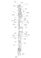
ここでは、図1及び図2を用いて、第1実施形態に係るフライホイール組立体1(ダンパー装置の一例)の説明を行う。フライホイール組立体1は、エンジンで発生した動力を、トランスミッションに伝達するための装置である。
入力プレート2には、エンジンの動力が入力される。入力プレート2には、エンジンで発生した動力が入力される。入力プレート2は、エンジン側に配置される。入力プレート2は、エンジンのクランクシャフト(図示せず)に固定される。
出力プレート3は、エンジンの動力をトランスミッションへと出力する。出力プレート3は、入力プレート2に対して回転可能に配置される。出力プレート3は、トランスミッションに連結される出力軸(図示しない)に、固定される。
サポートプレート4は、低剛性スプリング51と高剛性スプリング61とに、係合する。サポートプレート4は、低剛性スプリング51と高剛性スプリング61とを、直列に連結する。
低剛性スプリング51は、入力プレート2及び出力プレート3の間で円周方向に圧縮される。詳細には、低剛性スプリング51は、第1プレート21及び第2プレート22の第1押圧部27と、出力プレート3の第3押圧部34との間で、圧縮される。より詳細には、低剛性スプリング51は、第1プレート21及び第2プレート22の第1押圧部27と、サポートプレート4の係合部43との間で、圧縮される。また、低剛性スプリング51は、サポートプレート4の係合部43と、出力プレート3の第3押圧部34との間で、圧縮される。
高剛性スプリング61は、入力プレート2及び出力プレート3の間で円周方向に圧縮される。詳細には、高剛性スプリング61は、第1プレート21及び第2プレート22の第2押圧部28と、出力プレート3の第3押圧部34との間で、圧縮される。より詳細には、高剛性スプリング61は、第1プレート21及び第2プレート22の第2押圧部28と、サポートプレート4の係合部43との間で、圧縮される。また、高剛性スプリング61は、サポートプレート4の係合部43と、出力プレート3の第3押圧部34との間で、圧縮される。
第1ストッパ機構81は、入力プレート2及び出力プレート3のいずれか一方と、サポートプレート4とを当接させることによって、低剛性スプリング51の作動を停止する。
第2ストッパ機構85は、入力プレート2及び出力プレート3のいずれか他方と、サポートプレート4とを当接させることによって、高剛性スプリング61の作動を停止する。
第1緩衝部材71は、低剛性スプリング51の作動中に第1ストッパ機構81の作動を緩和可能である。第1緩衝部材71は、弾性部材である。具体的には、第1緩衝部材71は、樹脂製の弾性部材である。なお、以下では、「捩り角度」という文言は、「捩り角度の絶対値」という意味で用いられることがある。
第2緩衝部材75は、高剛性スプリング61の作動中に第2ストッパ機構85の作動を緩和可能である。第2緩衝部材75が、弾性部材である。具体的には、第2緩衝部材75は、樹脂製の弾性部材である。
位置決め構造90は、サポートプレート4を、内周側において、入力プレート2及び出力プレート3の少なくともいずれか一方に対して、半径方向に位置決めする。ここでは、位置決め構造90が、サポートプレート4を、内周側において、入力プレート2に対して、半径方向に位置決めする。
図3を用いて、フライホイール組立体1の動作(捩り特性)について説明する。図3の横軸は捩り角度θであり、図3の縦軸はトルクである。なお、本実施形態のフライホイール組立体1は、3組のスプリング群、すなわち低剛性スプリング51及び高剛性スプリング61が直列配置された3組のスプリング群を、有している。1組のスプリング群は、低剛性スプリング51と、高剛性スプリング61とから構成されている。ここでは、説明を容易にするために、1組のスプリング群に注目して説明を行う。
まず、エンジンの動力がフライホイール組立体1に入力され、入力プレート2が、出力プレート3に対して第1方向(図1のR1方向)に回転し始める。すると、入力プレート2と出力プレート3との間で、低剛性スプリング51及び高剛性スプリング61の圧縮が、開始される。
負側の捩り特性は、実質的に、正側の捩り特性と同様であるので、ここでは図3を用いて説明する。すなわち、図3の捩り角度θを絶対値と考えると、図3が負側の捩り特性を示す図となる。
ここでは、図4を用いて、第2実施形態に係るフライホイール組立体1(ダンパー装置の一例)の説明を行う。第2実施形態のフライホイール組立体1の構成及び動作は、位置決め構造90を除いて、第1実施形態と同じである。このため、ここでは、位置決め構造90に関する構成のみ詳細に説明を行い、位置決め構造90に関係しない構成については、簡単な説明又は省略する。また、ここで省略された説明については、第1実施形態の説明に準ずる。なお、図4の符号は、第1実施形態と同様の構成については、同じ符号を付している。
出力プレート3は、エンジンの動力をトランスミッションへと出力する。出力プレート3は、入力プレート2に対して回転可能に配置される。
サポートプレート4は、低剛性スプリング51と高剛性スプリング61とに、係合する。サポートプレート4は、低剛性スプリング51と高剛性スプリング61とを、直列に連結する。サポートプレート4は、円環状の本体部41と、突出部41aと、第2当接部42(図1を参照)と、係合部43(図1を参照)と、回転規制部44とを、有している。なお、第2当接部42と、係合部43と、回転規制部44とは、第1実施形態と同じ構成であるので、ここでは説明を省略する。
位置決め構造90は、サポートプレート4を、内周側において、入力プレート2及び出力プレート3の少なくともいずれか一方に対して、半径方向に位置決めする。ここでは、位置決め構造90が、サポートプレート4を、内周側において、出力プレート3に対して、半径方向に位置決めする。
(1)本ダンパー装置は、入力プレート2と、出力プレート3と、低剛性スプリング51及び高剛性スプリング61と、サポートプレート4と、位置決め構造90とを、備えている。入力プレート2には、エンジンの動力が入力される。出力プレート3は、入力プレート2に対して回転可能に配置される。低剛性スプリング51及び高剛性スプリング61は、入力プレート2及び出力プレート3の間で圧縮される。サポートプレート4は、低剛性スプリング51及び高剛性スプリング61それぞれに係合し、低剛性スプリング51及び高剛性スプリング61を連結する。位置決め構造90は、サポートプレート4を、内周側において、入力プレート2及び出力プレート3の少なくともいずれか一方に対して、半径方向に位置決めする。
本発明はかかる実施形態に限定されるものではなく、本発明の範囲を逸脱することなく種々の変形及び修正が可能である。
2 入力プレート
3 出力プレート
4 サポートプレート
24 補強部材
21a 連結部
41 本体部
41a 突出部
46 サポートプレートの内周部
47 支持部
51 低剛性スプリング
61 高剛性スプリング
71 第1緩衝部材
75 第2緩衝部材
81 第1ストッパ機構
85 第2ストッパ機構
90 位置決め構造
Claims (7)
- エンジンの動力が入力される第1回転部材と、
前記第1回転部材に対して回転可能に配置された第2回転部材と、
前記第1回転部材及び前記第2回転部材の間で圧縮される複数のコイルスプリングと、
前記第1回転部材及び前記第2回転部材に対して相対回転自在に配置され、前記複数のコイルスプリングの内周側に配置された円環状の本体部と、前記本体部から径方向外方に延びて形成され前記複数のコイルスプリングに係合する複数の係合部と、を有し、複数の前記コイルスプリングを連結する中間部材と、
前記中間部材を、内周側において、前記第1回転部材及び前記第2回転部材の少なくともいずれか一方に対して、半径方向に位置決めする位置決め構造と、
前記第1回転部材及び前記第2回転部材の少なくともいずれか一方と、前記中間部材と、を当接させることによって前記複数のコイルスプリングのうちの少なくともいずれかの作動を停止するためのストッパ機構と、
を備えるダンパー装置。 - エンジンの動力が入力される第1回転部材と、
前記第1回転部材に対して回転可能に配置された第2回転部材と、
前記第1回転部材及び前記第2回転部材の間で圧縮される複数のコイルスプリングと、
複数の前記コイルスプリングそれぞれに係合し、複数の前記コイルスプリングを連結する中間部材と、
前記中間部材を、内周側において、前記第1回転部材及び前記第2回転部材の少なくともいずれか一方に対して、半径方向に位置決めする位置決め構造と、
を備え、
前記第2回転部材は、前記コイルスプリングの内周側に配置される円環部と、前記円環部から半径方向外方に延び前記コイルスプリングを押圧可能な押圧部と、を有し、
前記中間部材は、前記コイルスプリングの内周側に配置される本体部と、前記本体部から半径方向外方に延び複数の前記コイルスプリングそれぞれに係合可能な係合部と、を有し、
前記押圧部と前記係合部とは、円周方向に並べて配置されている、
ダンパー装置。 - 前記第1回転部材には、前記中間部材の内周部を支持する支持部が、設けられ、
前記位置決め構造は、前記中間部材の内周部と、前記支持部とから、構成される、
請求項1又は2に記載のダンパー装置。 - 前記第1回転部材は、エンジンに連結するための連結部を、有し、
前記支持部は、前記連結部を補強するための補強部材である、
請求項3に記載のダンパー装置。 - 前記中間部材は、本体部と、軸方向に前記本体部から突出した突出部とを、有し、
前記第2回転部材は、前記突出部を支持可能な支持部を、有し、
前記位置決め構造は、前記突出部と、前記支持部とから、構成される、
請求項1又は2に記載のダンパー装置。 - 前記突出部は、前記本体部の内周部を折り曲げることによって形成され、
前記支持部の内周部は、前記突出部の外周部を支持する、
請求項5に記載のダンパー装置。 - 前記第1回転部材、前記中間部材、及び前記第2回転部材は、内周側において、軸方向に、前記第1回転部材、前記中間部材、前記第2回転部材の順に、配置される、
請求項1から6のいずれか1項に記載のダンパー装置。
Priority Applications (3)
| Application Number | Priority Date | Filing Date | Title |
|---|---|---|---|
| JP2014037397A JP6301158B2 (ja) | 2014-02-27 | 2014-02-27 | ダンパー装置 |
| US14/622,042 US9599187B2 (en) | 2014-02-27 | 2015-02-13 | Damper device |
| CN201510084499.3A CN104879439B (zh) | 2014-02-27 | 2015-02-16 | 阻尼装置 |
Applications Claiming Priority (1)
| Application Number | Priority Date | Filing Date | Title |
|---|---|---|---|
| JP2014037397A JP6301158B2 (ja) | 2014-02-27 | 2014-02-27 | ダンパー装置 |
Publications (2)
| Publication Number | Publication Date |
|---|---|
| JP2015161372A JP2015161372A (ja) | 2015-09-07 |
| JP6301158B2 true JP6301158B2 (ja) | 2018-03-28 |
Family
ID=53881794
Family Applications (1)
| Application Number | Title | Priority Date | Filing Date |
|---|---|---|---|
| JP2014037397A Active JP6301158B2 (ja) | 2014-02-27 | 2014-02-27 | ダンパー装置 |
Country Status (3)
| Country | Link |
|---|---|
| US (1) | US9599187B2 (ja) |
| JP (1) | JP6301158B2 (ja) |
| CN (1) | CN104879439B (ja) |
Cited By (1)
| Publication number | Priority date | Publication date | Assignee | Title |
|---|---|---|---|---|
| US12006997B2 (en) | 2018-12-26 | 2024-06-11 | Aisin Corporation | Damper device |
Families Citing this family (2)
| Publication number | Priority date | Publication date | Assignee | Title |
|---|---|---|---|---|
| JP6822113B2 (ja) | 2016-12-13 | 2021-01-27 | アイシン精機株式会社 | ダンパ装置 |
| CN110273976A (zh) * | 2019-07-30 | 2019-09-24 | 吉林大学 | 具有非线性扭转特性且适应汽车多工况的双质量飞轮 |
Family Cites Families (12)
| Publication number | Priority date | Publication date | Assignee | Title |
|---|---|---|---|---|
| US5146811A (en) * | 1990-12-24 | 1992-09-15 | Luk Lamellen Und Kupplungsbau Gmbh | Vibration damping apparatus |
| DE4425570B4 (de) * | 1994-07-20 | 2007-08-02 | Zf Sachs Ag | Zweimassenschwungrad |
| FR2723997B1 (fr) * | 1994-08-29 | 1996-11-08 | Valeo | Amortisseur de torsion refroidi par circulation d'air |
| DE19611184C2 (de) * | 1996-03-21 | 1998-04-09 | Mannesmann Sachs Ag | Drehschwingungsdämpfer |
| JPH11325107A (ja) * | 1998-05-15 | 1999-11-26 | Exedy Corp | ダンパーディスク組立体 |
| DE19952143A1 (de) * | 1998-11-05 | 2000-05-11 | Luk Lamellen & Kupplungsbau | Bauteil zur Verbindung mit einer Kurbelwelle und Verfahren zu dessen Herstellung |
| JP4522220B2 (ja) * | 2004-10-19 | 2010-08-11 | 株式会社エクセディ | ダンパーディスク組立体 |
| JP4999437B2 (ja) * | 2006-12-04 | 2012-08-15 | 株式会社エクセディ | トルクコンバータ |
| JP2009243599A (ja) * | 2008-03-31 | 2009-10-22 | Aisin Aw Co Ltd | ダンパ装置 |
| DE102011089250A1 (de) * | 2011-01-24 | 2012-07-26 | Schaeffler Technologies Gmbh & Co. Kg | Torsionsschwingungsdämpfer sowie Dämpfer- und Drehmomentübertragungseinrichtung |
| JP5639911B2 (ja) | 2011-01-31 | 2014-12-10 | ヴァレオユニシアトランスミッション株式会社 | 捩りダンパ装置 |
| JP5742326B2 (ja) * | 2011-03-15 | 2015-07-01 | アイシン精機株式会社 | トルク変動吸収装置 |
-
2014
- 2014-02-27 JP JP2014037397A patent/JP6301158B2/ja active Active
-
2015
- 2015-02-13 US US14/622,042 patent/US9599187B2/en active Active
- 2015-02-16 CN CN201510084499.3A patent/CN104879439B/zh active Active
Cited By (1)
| Publication number | Priority date | Publication date | Assignee | Title |
|---|---|---|---|---|
| US12006997B2 (en) | 2018-12-26 | 2024-06-11 | Aisin Corporation | Damper device |
Also Published As
| Publication number | Publication date |
|---|---|
| CN104879439A (zh) | 2015-09-02 |
| CN104879439B (zh) | 2019-01-08 |
| JP2015161372A (ja) | 2015-09-07 |
| US9599187B2 (en) | 2017-03-21 |
| US20150240910A1 (en) | 2015-08-27 |
Similar Documents
| Publication | Publication Date | Title |
|---|---|---|
| JP6559399B2 (ja) | ダンパー装置 | |
| JP6274796B2 (ja) | 自動車用のトルク伝達装置 | |
| KR102520861B1 (ko) | 토크 변동 억제 장치, 토크 컨버터 및 동력 전달 장치 | |
| KR102265136B1 (ko) | 개선된 댐핑 수단을 구비하는 이중 댐핑 플라이휠 | |
| JP5272853B2 (ja) | トルク変動吸収装置 | |
| JP5980818B2 (ja) | クラッチのためのトーショナルダンパ | |
| WO2015064237A1 (ja) | フライホイール組立体 | |
| JP6756129B2 (ja) | ダンパ装置 | |
| JP6219749B2 (ja) | ダンパー装置 | |
| JP6301158B2 (ja) | ダンパー装置 | |
| JP2008039113A (ja) | スプリングシート及びスプリング組立体 | |
| JP2014224560A (ja) | トルクコンバータのロックアップ装置 | |
| CN204610687U (zh) | 阻尼器装置 | |
| JP2014206237A (ja) | 捩り振動減衰装置 | |
| JP5688113B2 (ja) | トルクコンバータ用のロックアップ装置 | |
| JP2007285335A (ja) | 捩り振動低減装置 | |
| JP4956496B2 (ja) | 捩り振動低減装置 | |
| JP5030846B2 (ja) | 捩り振動低減装置 | |
| JP6679359B2 (ja) | スプリング組立体、及びスプリング組立体を備えるダンパ装置。 | |
| JP2019090428A (ja) | ダンパディスク組立体 | |
| JP2023545193A (ja) | トルクリミッター、トランスミッションシステム、および該トルクリミッターを組立てるための方法 | |
| EP2963311A2 (en) | Damper device | |
| KR102090212B1 (ko) | 토셔널 댐퍼 | |
| WO2018051705A1 (ja) | ダンパ装置 | |
| JP2016217521A (ja) | トルク変動吸収装置 |
Legal Events
| Date | Code | Title | Description |
|---|---|---|---|
| A621 | Written request for application examination |
Free format text: JAPANESE INTERMEDIATE CODE: A621 Effective date: 20160823 |
|
| A977 | Report on retrieval |
Free format text: JAPANESE INTERMEDIATE CODE: A971007 Effective date: 20170531 |
|
| A131 | Notification of reasons for refusal |
Free format text: JAPANESE INTERMEDIATE CODE: A131 Effective date: 20170704 |
|
| A521 | Request for written amendment filed |
Free format text: JAPANESE INTERMEDIATE CODE: A523 Effective date: 20170901 |
|
| TRDD | Decision of grant or rejection written | ||
| A01 | Written decision to grant a patent or to grant a registration (utility model) |
Free format text: JAPANESE INTERMEDIATE CODE: A01 Effective date: 20180130 |
|
| A61 | First payment of annual fees (during grant procedure) |
Free format text: JAPANESE INTERMEDIATE CODE: A61 Effective date: 20180228 |
|
| R150 | Certificate of patent or registration of utility model |
Ref document number: 6301158 Country of ref document: JP Free format text: JAPANESE INTERMEDIATE CODE: R150 |
|
| R250 | Receipt of annual fees |
Free format text: JAPANESE INTERMEDIATE CODE: R250 |
|
| R250 | Receipt of annual fees |
Free format text: JAPANESE INTERMEDIATE CODE: R250 |