JP6286564B2 - Conduit guide tip - Google Patents
Conduit guide tip Download PDFInfo
- Publication number
- JP6286564B2 JP6286564B2 JP2016546035A JP2016546035A JP6286564B2 JP 6286564 B2 JP6286564 B2 JP 6286564B2 JP 2016546035 A JP2016546035 A JP 2016546035A JP 2016546035 A JP2016546035 A JP 2016546035A JP 6286564 B2 JP6286564 B2 JP 6286564B2
- Authority
- JP
- Japan
- Prior art keywords
- catheter
- tip
- tip portion
- guide
- distal
- Prior art date
- Legal status (The legal status is an assumption and is not a legal conclusion. Google has not performed a legal analysis and makes no representation as to the accuracy of the status listed.)
- Active
Links
- 239000007787 solid Substances 0.000 claims description 41
- 210000004204 blood vessel Anatomy 0.000 claims description 38
- 230000007704 transition Effects 0.000 claims description 26
- 238000004804 winding Methods 0.000 claims description 17
- 239000002991 molded plastic Substances 0.000 claims description 4
- 230000006835 compression Effects 0.000 claims description 3
- 238000007906 compression Methods 0.000 claims description 3
- 238000002347 injection Methods 0.000 claims description 3
- 239000007924 injection Substances 0.000 claims description 3
- 230000008878 coupling Effects 0.000 description 44
- 238000010168 coupling process Methods 0.000 description 44
- 238000005859 coupling reaction Methods 0.000 description 44
- 239000000463 material Substances 0.000 description 11
- 238000000034 method Methods 0.000 description 9
- 229920002614 Polyether block amide Polymers 0.000 description 8
- 238000003780 insertion Methods 0.000 description 8
- 230000037431 insertion Effects 0.000 description 8
- 229920000642 polymer Polymers 0.000 description 7
- 230000001225 therapeutic effect Effects 0.000 description 6
- 210000005166 vasculature Anatomy 0.000 description 6
- 238000003384 imaging method Methods 0.000 description 4
- 239000002184 metal Substances 0.000 description 4
- HLXZNVUGXRDIFK-UHFFFAOYSA-N nickel titanium Chemical compound [Ti].[Ti].[Ti].[Ti].[Ti].[Ti].[Ti].[Ti].[Ti].[Ti].[Ti].[Ni].[Ni].[Ni].[Ni].[Ni].[Ni].[Ni].[Ni].[Ni].[Ni].[Ni].[Ni].[Ni].[Ni] HLXZNVUGXRDIFK-UHFFFAOYSA-N 0.000 description 4
- 229910001000 nickel titanium Inorganic materials 0.000 description 4
- 238000001356 surgical procedure Methods 0.000 description 4
- 238000002560 therapeutic procedure Methods 0.000 description 4
- 206010058178 Aortic occlusion Diseases 0.000 description 3
- 239000003814 drug Substances 0.000 description 3
- 210000001105 femoral artery Anatomy 0.000 description 3
- 238000012986 modification Methods 0.000 description 3
- 230000004048 modification Effects 0.000 description 3
- 239000004033 plastic Substances 0.000 description 3
- 229920003023 plastic Polymers 0.000 description 3
- 206010053648 Vascular occlusion Diseases 0.000 description 2
- 238000002399 angioplasty Methods 0.000 description 2
- 238000005452 bending Methods 0.000 description 2
- 239000008280 blood Substances 0.000 description 2
- 210000004369 blood Anatomy 0.000 description 2
- 238000010586 diagram Methods 0.000 description 2
- 229940079593 drug Drugs 0.000 description 2
- 238000012377 drug delivery Methods 0.000 description 2
- 239000003527 fibrinolytic agent Substances 0.000 description 2
- 238000001914 filtration Methods 0.000 description 2
- 230000007246 mechanism Effects 0.000 description 2
- 229960000103 thrombolytic agent Drugs 0.000 description 2
- 208000021331 vascular occlusion disease Diseases 0.000 description 2
- 238000003466 welding Methods 0.000 description 2
- 208000005189 Embolism Diseases 0.000 description 1
- 239000004433 Thermoplastic polyurethane Substances 0.000 description 1
- 239000000853 adhesive Substances 0.000 description 1
- 230000001070 adhesive effect Effects 0.000 description 1
- 230000033115 angiogenesis Effects 0.000 description 1
- 210000000709 aorta Anatomy 0.000 description 1
- 210000001367 artery Anatomy 0.000 description 1
- 230000009286 beneficial effect Effects 0.000 description 1
- 229920000249 biocompatible polymer Polymers 0.000 description 1
- 210000002302 brachial artery Anatomy 0.000 description 1
- 238000010276 construction Methods 0.000 description 1
- 229920001577 copolymer Polymers 0.000 description 1
- 229920001971 elastomer Polymers 0.000 description 1
- 239000000806 elastomer Substances 0.000 description 1
- 229920003247 engineering thermoplastic Polymers 0.000 description 1
- 238000000605 extraction Methods 0.000 description 1
- 239000000945 filler Substances 0.000 description 1
- 239000012530 fluid Substances 0.000 description 1
- 239000006260 foam Substances 0.000 description 1
- 239000006261 foam material Substances 0.000 description 1
- 230000002439 hemostatic effect Effects 0.000 description 1
- 239000007788 liquid Substances 0.000 description 1
- 239000003550 marker Substances 0.000 description 1
- 229910001092 metal group alloy Inorganic materials 0.000 description 1
- 239000007769 metal material Substances 0.000 description 1
- 238000002360 preparation method Methods 0.000 description 1
- 230000011664 signaling Effects 0.000 description 1
- 239000010935 stainless steel Substances 0.000 description 1
- 229910001220 stainless steel Inorganic materials 0.000 description 1
- 210000003270 subclavian artery Anatomy 0.000 description 1
- 239000000126 substance Substances 0.000 description 1
- 229920002725 thermoplastic elastomer Polymers 0.000 description 1
- 229920002803 thermoplastic polyurethane Polymers 0.000 description 1
- 230000002792 vascular Effects 0.000 description 1
- 238000007631 vascular surgery Methods 0.000 description 1
- 210000003462 vein Anatomy 0.000 description 1
Images


Classifications
-
- A—HUMAN NECESSITIES
- A61—MEDICAL OR VETERINARY SCIENCE; HYGIENE
- A61M—DEVICES FOR INTRODUCING MEDIA INTO, OR ONTO, THE BODY; DEVICES FOR TRANSDUCING BODY MEDIA OR FOR TAKING MEDIA FROM THE BODY; DEVICES FOR PRODUCING OR ENDING SLEEP OR STUPOR
- A61M25/00—Catheters; Hollow probes
- A61M25/0067—Catheters; Hollow probes characterised by the distal end, e.g. tips
- A61M25/0068—Static characteristics of the catheter tip, e.g. shape, atraumatic tip, curved tip or tip structure
-
- A—HUMAN NECESSITIES
- A61—MEDICAL OR VETERINARY SCIENCE; HYGIENE
- A61M—DEVICES FOR INTRODUCING MEDIA INTO, OR ONTO, THE BODY; DEVICES FOR TRANSDUCING BODY MEDIA OR FOR TAKING MEDIA FROM THE BODY; DEVICES FOR PRODUCING OR ENDING SLEEP OR STUPOR
- A61M25/00—Catheters; Hollow probes
- A61M25/0067—Catheters; Hollow probes characterised by the distal end, e.g. tips
- A61M25/008—Strength or flexibility characteristics of the catheter tip
- A61M2025/0081—Soft tip
-
- A—HUMAN NECESSITIES
- A61—MEDICAL OR VETERINARY SCIENCE; HYGIENE
- A61M—DEVICES FOR INTRODUCING MEDIA INTO, OR ONTO, THE BODY; DEVICES FOR TRANSDUCING BODY MEDIA OR FOR TAKING MEDIA FROM THE BODY; DEVICES FOR PRODUCING OR ENDING SLEEP OR STUPOR
- A61M25/00—Catheters; Hollow probes
- A61M25/0067—Catheters; Hollow probes characterised by the distal end, e.g. tips
- A61M25/0082—Catheter tip comprising a tool
- A61M2025/0096—Catheter tip comprising a tool being laterally outward extensions or tools, e.g. hooks or fibres
-
- A—HUMAN NECESSITIES
- A61—MEDICAL OR VETERINARY SCIENCE; HYGIENE
- A61M—DEVICES FOR INTRODUCING MEDIA INTO, OR ONTO, THE BODY; DEVICES FOR TRANSDUCING BODY MEDIA OR FOR TAKING MEDIA FROM THE BODY; DEVICES FOR PRODUCING OR ENDING SLEEP OR STUPOR
- A61M25/00—Catheters; Hollow probes
- A61M25/0067—Catheters; Hollow probes characterised by the distal end, e.g. tips
- A61M25/0074—Dynamic characteristics of the catheter tip, e.g. openable, closable, expandable or deformable
-
- A—HUMAN NECESSITIES
- A61—MEDICAL OR VETERINARY SCIENCE; HYGIENE
- A61M—DEVICES FOR INTRODUCING MEDIA INTO, OR ONTO, THE BODY; DEVICES FOR TRANSDUCING BODY MEDIA OR FOR TAKING MEDIA FROM THE BODY; DEVICES FOR PRODUCING OR ENDING SLEEP OR STUPOR
- A61M25/00—Catheters; Hollow probes
- A61M25/01—Introducing, guiding, advancing, emplacing or holding catheters
Landscapes
- Health & Medical Sciences (AREA)
- Life Sciences & Earth Sciences (AREA)
- Biophysics (AREA)
- Pulmonology (AREA)
- Engineering & Computer Science (AREA)
- Anesthesiology (AREA)
- Biomedical Technology (AREA)
- Heart & Thoracic Surgery (AREA)
- Hematology (AREA)
- Animal Behavior & Ethology (AREA)
- General Health & Medical Sciences (AREA)
- Public Health (AREA)
- Veterinary Medicine (AREA)
- Media Introduction/Drainage Providing Device (AREA)
Description
本発明は、一般に、血管内のカテーテル、および、特に、展開中に患者の血管内を通してカテーテルをガイドするカテーテルチップに関する。 The present invention relates generally to intravascular catheters and, in particular, to catheter tips for guiding a catheter through a patient's blood vessel during deployment.
血管内の装置は、一般的に、治療手術中に血管の内腔に配置される装置である。治療手術は、例えば、ステントデリバリ、血管形成、粥腫切除、塞栓の濾過、大動脈の閉塞または血管内で行われるその他の治療手術のような幅広い手術のいずれか一つであってもよい。そのような手術において使用される血管内の装置は、概して、患者の血管の目標部位へアクセスするためのカテーテルまたはガイドワイヤを含む。 Intravascular devices are generally devices that are placed in the lumen of a blood vessel during therapeutic surgery. The therapeutic procedure may be any one of a wide range of procedures such as, for example, stent delivery, angioplasty, atherectomy, embolus filtration, aortic occlusion, or other therapeutic procedures performed in the blood vessel. Intravascular devices used in such surgery generally include a catheter or guide wire for accessing a target site in a patient's blood vessel.
一般的に、治療手術は、大腿動脈のような血管内にカテーテルまたはガイドワイヤを挿入することを含む。カテーテルは、その後血管及びその分岐血管に押し込まれ、カテーテルの末端部分が患者の血管内の目標部位に到達する。カテーテルが適切に配置されると、治療手術が実施される。 In general, therapeutic surgery involves inserting a catheter or guide wire into a blood vessel such as a femoral artery. The catheter is then pushed into the blood vessel and its branch vessel so that the distal portion of the catheter reaches a target site within the patient's blood vessel. Once the catheter is properly positioned, a therapeutic operation is performed.
患者の血管系において目標部位に至るまでの経路は一般に簡単なものではない。血管系は多くの血管を含み、その血管はさらに種々の大きさの別の血管へと分岐し、人体のほとんどあらゆる部位まで曲がりくねった経路を形成している。ある場面では、カテーテルの適正な配置を促進するために、画像が使われている。カテーテルの幾つかの箇所に設けた放射線不透過マーカを利用して、カテーテルを動かしながら、カテーテルの各部をX線画像またはその他の適当な形式の画像上で位置決めすることができる。しかしながら、画像の使用は、しばしば病院または他の施設の特別に用意された部屋のみで利用可能な特別な装置を必要とする。血管系の手術には、病院施設以外で緊急に行われるものがある。例えば、患者によっては、失血を抑えるために現場で大動脈閉塞装置を用いる必要がある。 The path to the target site in the patient's vasculature is generally not straightforward. The vasculature contains many blood vessels, which further branch into other blood vessels of various sizes, forming a tortuous path to almost every part of the human body. In some situations, images are used to facilitate proper placement of the catheter. Radiopaque markers provided at several locations on the catheter can be used to position each portion of the catheter on an x-ray image or other suitable type of image while moving the catheter. However, the use of images often requires special equipment that is available only in specially prepared rooms in hospitals or other facilities. Some vascular surgery is performed urgently outside hospital facilities. For example, some patients need to use an aortic occlusion device in the field to reduce blood loss.
患者が病院施設にいながら、血管にカテーテルを配置する治療手術をしなければ場合でも、特別な撮影装置を用いることなくカテーテルを配置することが好ましい。
治療内容によっては、患者を別の部屋に移動することなく、患者のベッドの傍でカテーテルを施術するのが望ましいことがある。
Even when a patient is in a hospital facility and does not perform a therapeutic operation for placing a catheter in a blood vessel, it is preferable to place the catheter without using a special imaging device.
Depending on the nature of the treatment, it may be desirable to perform a catheter beside the patient's bed without moving the patient to another room.
カテーテルの配置にまつわる別の難しさは、典型的なカテーテルの構造に由来する。カテーテルは、その先端に向かって遠位側に伸びている。場面によっては、カテーテルが患者血管系の曲がりくねった経路に沿って曲がりながら進む際に、カテーテル先端近傍に設けたガイドバルーンによってその先端が血管の中心に保たれる。さもなければ、カテーテル先端は、血管の中心に保たれることなく血管に押し込まれ、進行可能な別の分岐血管に進入することにもなりかねない。 Another difficulty with catheter placement stems from typical catheter construction. The catheter extends distally toward its tip. Depending on the scene, when the catheter advances while bending along a tortuous path of the patient's vasculature, the tip is kept at the center of the blood vessel by a guide balloon provided near the tip of the catheter. Otherwise, the catheter tip may be pushed into the blood vessel without being kept in the center of the blood vessel and enter another branch vessel that can be advanced.
特別な画像装置または特別な装置を用いることなく、患者の血管にカテーテルを挿入して該カテーテルを血管内の所望箇所に配置する方法が業界内で望まれている。 There is a need in the industry for a method of inserting a catheter into a patient's blood vessel and placing the catheter at a desired location within the blood vessel without the use of a special imaging device or special device.
上記を考慮して、装置は、患者の血管を通ってカテーテルをガイドするために提供される。本装置は、カテーテルの外径(しばしばここでは厚みと言及される)と実質的に等しい外径のカテーテルの遠位端で遠位に向かって延伸するカテーテルガイドチップを有する。カテーテルガイドチップは、カテーテルの縦軸に直角な少なくとも一つの軸に沿ったカテーテルの外径より大きい非圧縮状態での形状の先端部分まで遠位に拡大する少なくとも一つのガイド部材を有する。カテーテルガイドチップは、先端部分が圧縮された場合に先端部分より大きくなるが、先端部分が圧縮されていない場合に先端部分より小さくなるように、シースへの挿入のために変形しやすく、圧縮力がかかっていないときに非圧縮時の形状にその形状を回復するための弾力性がある。 In view of the above, a device is provided for guiding a catheter through a patient's blood vessel. The device has a catheter guide tip extending distally at the distal end of a catheter having an outer diameter substantially equal to the outer diameter of the catheter (often referred to herein as thickness). The catheter guide tip has at least one guide member that extends distally to an uncompressed shaped tip portion that is larger than the outer diameter of the catheter along at least one axis perpendicular to the longitudinal axis of the catheter. The catheter guide tip is larger than the distal end portion when the distal end portion is compressed, but is easily deformed for insertion into the sheath so that the distal end portion is smaller than the distal end portion when the distal end portion is not compressed. There is elasticity to restore the shape to the uncompressed shape when not applied.
本方法、システムおよび器具は、後述の説明においてある程度説明され、その説明から明確になり、または、それらの方法、器具およびシステムの実施によって習得し得る。それらの方法、器具およびシステムの利点は、添付された請求項において特に指し示される要素と結合によって実現され、成し遂げられる。前述の概要と後述の詳細な説明は模範的かつ説明的であるだけで、請求される本方法、器具およびシステムを限定しない。 The methods, systems and instruments will be described to some extent in the following description, will be apparent from the description, or may be learned by implementation of the methods, instruments and systems. The advantages of those methods, instruments and systems are realized and attained by means of the elements and combinations particularly pointed out in the appended claims. The foregoing summary and the following detailed description are exemplary and explanatory only and are not restrictive of the claimed methods, instruments, and systems.
添付する図面において、要素などは、本発明のいくつかの好ましい実施例の間の参照番号などによって特定される。 In the accompanying drawings, elements and the like are identified by reference numerals and the like between some preferred embodiments of the invention.
本発明による前述の特徴及び利点とその他の特徴及び利点は、添付図面と併せて読まれる後述の例示的な実施例の詳細な説明からより明白になり得る。詳細な説明および図面は、本発明の単なる1つの事例であって、添付された請求項によって定められる本発明の範囲およびそれらと均等の範囲を限定するものではない。 The foregoing and other features and advantages of the present invention may become more apparent from the following detailed description of exemplary embodiments, read in conjunction with the accompanying drawings. The detailed description and drawings are merely illustrative of the invention and do not limit the scope of the invention and its equivalents defined by the appended claims.
本発明は、様々な実施例に関連して説明するが、さらなる変更が可能であると理解すべきである。本件出願は、本件出願に開示されていないが本発明に関連する技術分野で公知の事項や通常に行われる事項を含めて、本発明の原理に基づくあらゆる変形例、用途、適用を含むことを意図している。 While the invention will be described in conjunction with various embodiments, it should be understood that further modifications are possible. This application includes all modifications, uses, and applications based on the principles of the present invention, including matters that are not disclosed in the present application but are known in the technical field related to the present invention and commonly practiced. Intended.
さらに、本発明は、カテーテルシステムと関連付けて説明される。カテーテルガイドチップは、限定的ではないが、例えば、血管の閉塞、血管形成、ステントデリバリ、粥腫切除、ドラッグデリバリ、イメージング、その他の同様のものを含む、血管介入物を含む様々な異なる治療上または診断上の指示(indications)のために、カテーテルとともに使用される。その発明の実施例が都合の良い使用を見つけたカテーテルシステムの適用は、例えば、大腿動脈、上腕動脈、鎖骨下動脈または何らかのその他の適当な血管のような何らかのアクセス部位を利用するものである。さらに、その発明の実施例が都合の良い使用を見つけた適用は、また、動脈同様に静脈を含む。 Furthermore, the present invention will be described in connection with a catheter system. Catheter guide tips include a variety of different therapeutics including, but not limited to, vascular interventions, including, for example, vascular occlusion, angiogenesis, stent delivery, atherectomy, drug delivery, imaging, and the like. Or used with catheters for diagnostic indications. Application of the catheter system for which embodiments of the invention have found convenient use is to utilize any access site such as, for example, the femoral artery, brachial artery, subclavian artery or some other suitable vessel. Furthermore, applications where embodiments of the invention have found convenient use also include veins as well as arteries.
後述の説明において、“近位の(proximal)”または“近位に(proximally)”の用語は、本発明のシステムが配置されるまたは配置されようとする体部位から離れた方向に向けられたカテーテル装置の部分または構成を意味する。反対に、“遠位の(distal)”または“遠位に(distally)”の用語は、本発明のシステムが配置されるまたは配置されようとする体部位に向けられたカテーテル装置の部分または構成を意味する。このようにして、例えば、近位のハブがカテーテルシステムの近位端に配置されるのに対して、以下に説明するカテーテルガイドチップは、カテーテルシステムの遠位端に配置される。 In the following description, the terms “proximal” or “proximally” are oriented away from the body part where the system of the present invention is or will be deployed. Refers to a portion or configuration of a catheter device. Conversely, the term “distal” or “distally” refers to a portion or configuration of a catheter device directed to a body part where the system of the present invention is or is to be placed. Means. Thus, for example, a proximal hub is disposed at the proximal end of the catheter system, while a catheter guide tip, described below, is disposed at the distal end of the catheter system.
図1は、血管内の治療手術を実施するためのカテーテルシステム100の模式的な図である。カテーテルシステム100は、血管内装置102と、カテーテル部材104と、近位ハブ106と、カテーテルガイドチップ108とを有する。血管内装置102は、望ましい血管内の治療手術を実施するための任意のメカニズム、構成物、システムまたはサブシステムであってもよい。血管内装置102の例は、限定的ではないが、血管閉塞装置(例えば、閉塞バルーン)、血管形成装置、ステントデリバリシステム、粥腫切除システム、ドラッグデリバリシステム、イメージングシステム、閉栓濾過システム等を含む。
FIG. 1 is a schematic diagram of a
カテーテル部材104は、患者の血管系、すなわち、患者の血管内に延伸し、血管内装置102を目標部位に配置するために血管内装置102に設けられる任意の適当なワイヤ、チューブ状構造体または棒状構造体であってもよい。カテーテル部材104は、適当な金属合金(例えば、ニチノール)もしくはステンレススティールのような生体適合性金属または生体適合性ポリマーから構成されてもよい。カテーテルの金属は、概して、治療手術によって、また、どのぐらいの期間カテーテルが患者の血管内に留置されるかによって決められる。カテーテル部材104は、例えば、バルーンに充填する液体を輸送し、血栓溶解剤のような薬剤もしくは他の治療上の物質を運搬し、または、センサと信号するために使用される一または複数の管腔を含んでいてもよい。
近位ハブ106は、カテーテルシステム100の近位端と血管内におけるカテーテルの部分との間で信号伝達するための任意の適当な装置であってもよい。近位ハブ106は、カテーテル内の管腔との間で流体をやりとりするために、例えば、ルアーロックのようなポートまたはフィッティングを含んでいてもよい。いくつかの例において、近位ハブ106は、また、患者の血管におけるカテーテルシステム100の位置範囲を決定するために、(標識のような)近位の終点またはメカニズムを提供する。
カテーテルガイドチップ108は、カテーテル部材104の遠位端から遠位先端に向かって遠位側に延伸する。カテーテルガイドチップ108はカテーテル部材104から延伸し、先端部分まで遠位に拡大する。先端部分は、カテーテル部材104の長軸に直角な少なくとも一つの軸に沿ってカテーテルの外径よりも大きな非圧縮状態での形状を有する。カテーテルガイドチップ108は、展開中はシースに挿入するために変形可能で、圧縮力がかかっていないときは非圧縮時の形状にその形状を回復させるような弾力性がある。
The
カテーテルガイドチップ108は、カテーテル部材104の延長部分であってもよく、カテーテル部材104と同様の材料で構成されていてもよい。代わりに、カテーテルガイドチップ104は、しっかりとカテーテル部材104の遠位端に取り付けられた構成物であってもよい。カテーテルガイドチップ108は、非圧縮状態で、血管の曲がりくねった経路にカテーテルを案内するのに都合のよい形状と大きさを有する。カテーテルガイドチップ108はまた、展開時に血管への損傷を防ぐために、組織を傷つけない形状を有する。
The
図2A〜2Gは、例示的なカテーテルガイドチップ200を複数の視点から見た図である。カテーテルガイドチップ200は、結合ポイント203でカテーテル部材204から延伸する先端部分202を有する。図2Bの断面A−Aにおける断面図である図2Cに図示するように、カテーテル部材204は、外径T1(厚み)を有し、先端部分202は、実質的に等しい外径で結合ポイント203から延伸する。先端部分202は、移行部分208へ延伸する。移行部分208では、先端部分202が、中実または管状の一般にまたは実質的に円筒状の断面から、巻回部分(コイル部)210における平らな中実または管状の断面に移行し始める。巻回部分210では、先端部分202は、カテーテル部材204の縦軸に直角なA軸に沿ったカテーテルの外径T1より大きい外径T2の非圧縮状態の形状を有する。非圧縮状態での先端部分202のサイズT2は、カテーテル部材204が血管に挿入されているときに先端部分202がより小さな血管に入るのを防ぐために十分に大きい。
2A-2G are views of an exemplary
カテーテル部材204は、図2BのB−B断面図におけるカテーテル部材204の断面図である図2Cおよび図2Eに示すように、カテーテル管腔222を含んでもよい。カテーテル部材204は、また、管腔222との間で流体が行き来するように流体接続されたカテーテル開口220を含んでもよい。カテーテル開口220は、血管にカテーテル部材204を通して薬剤または血栓溶解剤を送るために使用されてもよい。カテーテル開口220は、カテーテルシステムの特定の用途に応じて、センサや任意の他の機能のために使用されてもよい。先端部分202は、図2BのE−E断面の先端部分の断面図である図2Cおよび図2Fの232に図示されるように、中実であってもよい。代わりに、先端部分202は、中空の管または管状部材であってもよい。先端部分202は、結合ポイント203でカテーテル部材204の管腔222にはめ込まれる狭い部分230を含んでもよい。先端部分202は、カテーテル部材204に先端部分202をオーバーモールド成形することによって、または、先端部分202とカテーテル部材とが任意の方法によって230で熱的に結合されるように、カテーテル部材204に取り付けられてもよい。いくつかの実装例において、先端部分202とカテーテル部材204との連結は、それらの結合部位(たとえば、結合点203の領域)に加えられる高周波エネルギによって、行われる。任意の他の適当な方法または装置が、先端部分202とカテーテル204との間の結合のために使用される。例えば、他の技術としては、レーザー溶接、超音波溶接、熱風ノズル若しくはホットジョウボンダが含まれる。熱的に接続するために、スプリットダイボンダを使用してもよい。他の実装例では、先端部分202とカテーテル部材204との間の結合を確保するために、接着材が使用されてもよい。
The
図2A〜2Gにおけるカテーテルガイドチップ200の先端部分202の形状は非圧縮状態での形状である。先端部分202は、遠位側に延伸する中実部材または管状部材として形成されており、移行部分208で、平坦な中実断面または管状断面となっている。平坦な断面は、カテーテル部材204の長軸に直交する軸Aで径方向に伸びて巻回部分210を形成している。巻回部分210は、カテーテル部材204が巻回部分210へ平坦化し始める移行部分208において、または、移行部分208の向こう側に先端部分202の最遠位ポイント206が配置されるように、輪状に曲がっていてもよい。これにより、最遠位ポイント206が先端部分202の巻き部(巻いている部分)に多少なりとも確実に入ることになる。先端部分202の最遠位ポイント206が少なくとも移行ポイント208まで延伸しなければ、先端部分202の最遠位ポイント206がカテーテルの抜取りの間に血管壁面の何か(ステント、プラーク、切開、または、他装置等)に引っかかる可能性がある。例えば、カテーテルシステムが血管内にステントを適用するために展開する実装例において、先端部分202は、ステントの配置より遠位になるであろう。ステントが血管内に配置された後の抜取りの間に、先端部分202は、ステントを通り越して移動するであろう。先端部分202が単純な釣り針(hook)状で、最遠位ポイント206が移行ポイント208に向かう経路部分に到達しただけの場合、カテーテルの抜き取り中、先端部分202の最遠位ポイント206がステントを通過するときにそれに引っ掛かる危険性がある。
The shape of the
図2A〜2Gおよび特に図2Gに示される例において、巻回部分210は、中実または管状の平坦化された断面を有する。図2Gは、先端部分202が中実の部材である場合のD−D断面における巻回部分210の模式断面図である。展開中に、巻回部分210は、血管に挿入されたシースへの挿入のために真っ直ぐにされる。巻回部分210がシースを越えて血管に移動すると、巻回部分210はその巻き形状を回復する。平坦化された中実または管状の巻回部分210の断面によりその巻き形状を回復する。これにより、最遠位ポイント206が実質上、巻回部分210に整列し、一方または他方に歪むことはない。
In the example shown in FIGS. 2A-2G and particularly in FIG. 2G, the winding
図2A〜2Gを参照しながら説明される先端部分202の実装例において、先端部分202は、弾力性がある射出成型のプラスチック素材から構成されてもよい。この場合、先端部分202は、カテーテル部材204の長軸に沿って先端部分202が延伸して圧縮または変形できる。また、弾性により、もはや圧縮力や変形力が作用していないときは、先端部分はその形状を回復する。例えば、先端部分202は、熱可塑性のポリウレタンまたは重合体若しくは共重合体のポリエーテルブロックアミドのような、PEBAX(商標名)であるエンジニアリング熱可塑性エラストマのような、弾力性のある熱可塑性エラストマのプラスチック素材から構成されてもよい。先端部分202はまた、該先端部分を延ばすことにより圧縮または形状を変えて該先端部分202をカテーテル部材204の長軸に沿って真っ直ぐにすることができる柔軟な金属材料(例えば、成形ニチノール金属)で作ってもよい。先端部分202が圧縮されていないとき、先端部分202はその非圧縮状態の形状に戻っている。望まれれば、金属の先端部分202は、被覆プラスチック素材でコートまたはカバーしてもよい。この場合、圧縮力が解放された状態で、先端部分202は、圧縮性と弾性を維持するか、または、圧縮性と弾性が向上される。
In the mounting example of the
カテーテルシステム100(および様々な実施形態の対応する部分)の先端部分108(および様々な実施形態の対応する部分)は、非常に柔らかく組織を傷つけることがないチップを有し、チップが血管内を進行する際に該血管に穴をあけたり破ったりすることがないようにしてある。カテーテルシャフトは、一般に、押出し性を提供し、座屈を防止するために、硬くする必要がある。したがって、カテーテルシステムの先端部分は、比較的硬いシャフト部分から非常に軟らかいチップへ移行する。その移行は、一ステップでまたは一連のステップ全体で起こり得る。限定的ではないが、一例として、本発明のカテーテルシステム200の一実施形態(および様々な実施形態の対応部分)は、PEBAXポリマー(商標名)からなるカテーテル部材204を有する。カテーテル部材204は、72デュロメータ硬さを有し、中央管腔222を通る同軸のニチノールの小径管(hypotube)を有する。このカテーテル部材は、良好な押出し性を有するほどに硬く、また、大動脈閉塞に耐える。ニチノール小径管は、任意の膨張可能な部材(例えば、カテーテルシステムによって搬送されるバルーン等)の末端で終了する。カテーテル部材は、なお、72D硬さのPEBAXポリマー(商標名)である。カテーテル先端部分202は、より柔軟で、40Dのような、かなり低い硬さを有するが、チップを非外傷性にするためにPEBAXポリマー(商標名)から構成されてもよい。あるカテーテルシステムでは、通常はカテーテルの他の部分の設計に応じて、カテーテル部材204の高いデュロメータ硬さから先端部分204の低いデュロメータに亘って、段階的に(例えば72D,60D,55D,40D,35D,その他)に変化する。
The tip portion 108 (and corresponding portion of various embodiments) of the catheter system 100 (and corresponding portion of various embodiments) has a tip that is very soft and does not damage tissue, and the tip is within the blood vessel. When proceeding, the blood vessel is prevented from being punctured or broken. Catheter shafts generally need to be stiff to provide extrudability and prevent buckling. Thus, the distal portion of the catheter system transitions from a relatively hard shaft portion to a very soft tip. The transition can occur in one step or in a whole series of steps. By way of example and not limitation, one embodiment of the
加えて、72Dの硬さを有するPEBAX(商標名)ポリマーからなる管状部材としてのカテーテル部材204から、40Dの硬さを有するPEBAX(商標名)ポリマーからなる中実の先端部分202に移行することが有益である。もしも、先端部分が、中実なものではなくチューブであったら、それが40Dの硬さを有するPEBAX(商標名)ポリマーで構成されていたとしても、それが潰れ、捩じれ、とても脆いなどのため、同様に機能しないであろう。しかしながら、本願の説明を考慮して、先端部分の硬さは、先端部分の構造、形状(管状であるか中実であるか)等に基づいて、非外傷性チップになるように調整できる。
In addition, transition from the
イントロデューサーシースによる患者の血管系への挿入に備えて、先端部分202は、イントロデューサーシースのバルブに容易に挿入できるように圧縮された状態で真っ直ぐにされる。イントロデューサーシースは、一般に、大腿動脈のような血管へアクセスするために使用され、しばしば失血を最小化するための止血バルブを有する。イントロデューサーシースのバルブを通してカテーテルチップを容易に挿入するために、先端部分202を圧縮状態へと真っ直ぐにする剥ぎ取りシース挿入器具を使用してもよい。剥ぎ取りシースは、カテーテルを挿入シースに挿入することを補助した後はカテーテルから剥ぎ取られて該カテーテルから分離される。先端部分202がイントロデューサーシースを抜けると、図2Aに示すように、それは自動的に非圧縮状態または変形のない状態にその形状が再形成される。先端部分202の形状はガイドとして使用され、カテーテルは血管を通る所望の経路を確実に辿ることになる。
In preparation for insertion into the patient's vasculature by the introducer sheath, the
図2A〜2Gに図示される例において、カテーテルガイドチップ200の先端部分202は、カテーテル部材204の遠位端に取り付けられている。他の実装例において、カテーテルガイドチップ200は、カテーテル部材204の延長部分として形成されてもよい。図2A〜2Gに図示される例における先端部分202はまた、中実のコアを有する。他の実装例における先端部分202は、望まれるなら、さらなる柔軟性を提供する内腔または中空のコアを含んでもよい。図2A〜2Gの例におけるカテーテルガイドチップ200の先端部分202は、また、巻き状の部材または巻回された部材として形成される。しかしながら、他の実装例における先端部分は、カテーテル部材の外径より大きく、かつ、より小さな血管ではなく、大動脈のようなより大きい血管に入るのに十分なサイズに拡大する任意の適当な形状を有していてもよい。
In the example illustrated in FIGS. 2A-2G, the
図3A〜3Cは、他の例のカテーテルガイドチップ300の異なる図である。カテーテルガイドチップ300は、カテーテル部材(図不掲載)から延伸する先端部分302を含む。先端部分302は、カテーテル結合部分303に沿って、先端部分302が球根状部分306を形成するサイズに拡大する移行部分304に延伸する。先端部分302の球根状部分306は、カテーテル部材の長軸に直交する軸Aに沿って、非変形状態で全体が所定外径の形状を有する。この外径はカテーテル部材の外形よりも大きい。先端部分302は、球根状部分306から遠位に遠位管状延長308まで延伸する。図3Cに示すように、先端部分302のカテーテル結合部分303は、また先端部分の内部空間312を含む球根状部分306に向かって長軸方向に延伸する内部空間310を有する。内部空間310と先端部分内部空間312は、カテーテル結合部分303と先端部分302とに柔軟性および弾力性を持たせるので、カテーテルガイドチップ300は変形しやすく、圧縮力がかかっていないときにその球根状の形状を回復する。先端部分302の柔軟性および弾力性は、先端部分302が構成されている材料の性質と、先端部分302の外表面と先端部分内部空間312の内表面との間の寸法とに依存している。
3A-3C are different views of another example
図4A〜4Cは、他の例のカテーテルガイドチップ400の異なる図である。カテーテルガイドチップ400は、カテーテル部材(図不掲載)からカテーテル結合部分408に沿って延伸する先端部分402を含む。先端部分402は、図3A〜3Cにおけるカテーテルガイドチップ300の先端部分302の形状と類似する球根形状404を有する。先端部分402は、球根形状404から遠位に向かって遠位の中実または管状の延長部分まで延伸する。カテーテル結合部分408は、カテーテル結合部分408を通して延伸するカテーテル内部空間410を有する先端部分402の球根形状404に向かって、および、球根形状404を通して延伸してもよい。カテーテル結合部分408は、図2A〜2Gを参照して上記で説明したカテーテル部材の遠位端に結合する先端部分402の中実または管状の部分であってもよい。代わりに、カテーテル結合部分408と先端部分402とは、カテーテル部材の延長部分であってもよい。
4A-4C are different views of another example
先端部分402の球根形状404は、球根形状404の内部空間に空間充填物412を含んでもよい。空間充填物412は、泡状物質、多孔性のプラスチックまたは任意の他の適当な圧縮性の材料から構成されてもよく、球根形状404に一体的に形成され、または、球根形状の内部に別に挿入され、若しくは、取り付けられてもよい。実施例において、球根形状404の内部空間は単純に空気であってもよい。
The
図5A〜5Cは、他の例のカテーテルガイドチップ500の異なる図である。カテーテルガイドチップ500は、先端部分502のカテーテル結合部分508から延伸する先端部分502を含む。カテーテル結合部分508は、図2A〜2Gを参照して説明されるカテーテル部材(図不掲載)に取り付けてもよい。先端部分502は球根形状504を有する。球根形状504は、先端部分502が図3A〜3Cまたは図4A〜4Cの管状延長308または406のように球根形状504から遠位側に延伸する管状延長を備えていないという点を除いて、カテーテルガイドチップ400の先端部分402の形状に類似している。カテーテル結合部分508は、先端部分702の球根形状504をカテーテル結合部分508に結合する移行部分506に延伸する。カテーテル結合部分508は、カテーテル結合部分508の長さにわたって延伸するカテーテル内部空間510を有する。移行部分506は、カテーテル結合部分508の外径より大きな外径を有する部分であり、一直線のカテーテル結合部分508と球根形状504との間の移行部分に所定の硬さを与えている。球根形状504は、圧縮力がかかったときに先端部分502の球根形状504を変形させるために先端部分内部空間512を有する。先端部分内部空間512は、泡状物質または他の圧縮性素材が充填されていてもよい。
5A-5C are different views of another example
図6A〜6Cは、他の例のカテーテルガイドチップ600の異なる図である。カテーテルガイドチップ600は、カテーテル部材(図不掲載)と結合するためにカテーテル結合部分608から延伸する先端部分602を含む。カテーテル結合部分608は移行部分606まで延伸する。移行部分606は、図5A〜5Cにおけるカテーテルガイドチップ500の先端部分502の形状と同様な球根形状604まで拡大する。カテーテル結合部分608は、カテーテル結合部分608の長さにわたって延伸するカテーテル内部空間610を有する。移行部分606は、移行部分606の外径を拡大することなく、球根形状604へ拡大している。球根形状604は、図6Cに示す例において、圧縮性素材612で満たされる内部空間を有する。他の例において、球根形状604の内部空間は空気で満たされる。
6A-6C are different views of another example
図7A〜7Cは、カテーテルガイドチップ700の他の例における異なる図である。カテーテルガイドチップ700は、図3A〜3Cにおけるカテーテルガイドチップ300と同様である。図7A〜7Cにおけるカテーテルガイドチップ700は、球根形状704まで遠位側に延伸するカテーテル結合部分702を含む。カテーテル結合部分702は内部空間706を有し、球根形状704は、図3A〜3Cにおけるカテーテルガイドチップ300と同様の先端部分内部空間708を有する。また、カテーテルガイドチップ700は、球根形状704から遠位に遠位管状延長712に向かって延伸する。位置合せピン(整列ピン)710は、カテーテル結合部分702の内部空間706に差し込まれており、先端部分内部空間708を通して遠位に遠位管状延長712内に延伸する。位置合せピン710は、それが球根形状704より硬い任意の適当な材料から構成されてもよい。位置合せピン710は、(カテーテル自体と同様に)カテーテル結合部分702と同軸上に遠位管状延長712を保持すると同時に、遠位管状延長712が径方向に圧縮する際に遠位側に延伸することを確実にする。位置合せピン710は、カテーテルガイドチップ700がそれ自体折り曲がることを防止する。
7A-7C are different views of another example of the
図8A〜8Cは、他の例のカテーテルガイドチップ800の異なる図である。また、カテーテルガイドチップ800は、図3A〜3Cのカテーテルガイドチップ300と同様である。図8A〜8Cにおけるカテーテルガイドチップ800は、遠位側に球根形状804にまで延伸するカテーテル結合部分802を含む。カテーテル結合部分802は内部空間806を含み、球根形状804は、図3A〜3Cのカテーテルガイドチップ300と同様の先端部分内部空間808を含む。また、カテーテルガイドチップ800は、球根形状804から遠位の中実または管状の延長812まで遠位側に延伸する。球根形状804は、カテーテル結合部分802の内部空間806から先端部分内部空間808内に延伸する球根形状フレーム810を含み、遠位側が中実または遠位管状の延長812に保持される。球根形状フレーム810は、それが球根形状804を頑丈にしながら圧縮性を維持するように、任意の適当な材料から構成されてもよい。球根形状フレーム810は、径方向に圧縮されると遠位の中実または管状の延長部812が遠位側に延伸し、その間、遠位の中実または管状の延長部812がカテーテル結合部分802と同軸に保持される、ことを確実にしている。また、球根形状フレームはカテーテルガイドチップ800の折り曲がりを防止する。
8A-8C are different views of another example
図9A〜9Cは、他の例のカテーテルガイドチップ900の異なる図である。カテーテルガイドチップ900は、複数のガイド部材904を有する先端部分902を有する。複数のガイド部材904は、カテーテル結合部分908から延長する中実または管状の部分905から放射状に延伸する。中実または管状の部分905は、少なくとも一つのガイド部材904を越えて、遠位の中実または管状の端部906まで延伸する。図9A〜9Cに図示される複数のガイド部材904は、中実または管状の部分905から放射状に伸びる平坦な部材である。そのために、展開中にカテーテルが患者の血管に挿入されているときに、先端部分902がより小さな血管に入り込むのを防止するため、先端部分902が、カテーテル結合部分908の外径T1より長い寸法T2に拡径する。ガイド部材904は、カテーテル結合部分908の長軸に直角な方向に平坦に伸びている。図9A〜9Cにおける先端部分902は、射出成型されたプラスチックから構成されている。これにより、先端部分902はそこに圧縮力が作用すると変形するように圧縮可能である。同時に、先端部分902は弾力性があるため、圧縮力が取り除かれたときにその通常形状に戻る。
9A-9C are different views of another example
図10A〜10Cは、他の例のカテーテルガイドチップ1000の異なる図である。カテーテルガイドチップ1000は、複数のガイド部材1004を有する先端部分1002を有する。複数のガイド部材1004は、カテーテル結合部分1008から遠位に延長する、中実または管状の部分1005から放射状に延伸する。管状部分1005は、少なくとも一つのガイド部材1004を越えて、中実または管状の先端1006まで遠位側に延伸する。図10A〜10Cに示すような複数のガイド部材1004は、中実または管状の部分1005から曲線に沿って放射状に伸びる長軸方向に平坦な部材である。図10A〜10Cのガイド部材1004は、図10Bに示す湾曲部材のように放射状に延伸する。しかしながら、その他の実施形態において、ガイド部材1004は、また、直線に延伸する部材のように延伸してもよい。また、図10A〜10Cの先端部分1002は、圧縮可能な射出成型プラスチックから構成されてもよい。
10A-10C are different views of another example
図11A〜11Cは、他の例のカテーテルガイドチップ1100の異なる図である。カテーテルガイドチップ1100は、複数のガイド部材1104を有する先端部分1102を有する。複数のガイド部材1104は、カテーテル結合部分1112から遠位側に伸びる中実または管状の部分1105から放射状に延伸する。狭小な首部分1107は、カテーテル結合部分1112を中実または管状の部分1105に結合する。中実または管状の部分1105は、少なくとも一つのガイド部材1104を越えて、遠位側の中実または管状の先端1106まで延伸する。ガイド部材1104は、実質上、先端部分1102の管状部分1105から放射状に伸びる中実または管状のガイド部材である。図11A〜11Cに示す例において、実質的な中実または管状のガイド部材は、患者の血管を通して移動する、より非外傷的な構造を提供する球状先端1110を有する。
11A-11C are different views of another example
図12A〜12Cは、他の例のカテーテルガイドチップ1200の異なる図である。カテーテルガイドチップ1200は、複数のガイド部材1204を有する先端部分1202を有する。複数のガイド部材1204は、カテーテル結合部分1210から遠位側に伸びる中実または管状の部分1205から放射状に延伸する。中実または管状の部分1205は、少なくとも一つのガイド部材1204を越えて、遠位側の管状先端1208まで延伸する。図12A〜12Cのガイド部材1204は、長軸方向に伸びるとともに、中実または管状の部分1205から外に向かって放射方向外側に向けて伸び、その後中実または管状の部分1205に戻って結合するように放射方向内側に向かって延伸する。図12A〜12Cの複数のガイド部材1204は、実質的に、カテーテルの展開時に先端部分1202がより小さな血管に入り込むのを防止するサイズの球根形状フレームを形成する。
12A-12C are different views of another example
図13A〜13Cは、他の例のカテーテルガイドチップ1300の異なる図である。カテーテルガイドチップ1300は、先端部分1302を含む。先端部分1302は、カテーテル結合部1310から遠位側に伸びる中実または管状の部分1305から径方向に伸びる、第1の複数のガイド部材1306と第2の複数のガイド部材1304を含む。第2の複数のガイド部材1304は、第1の複数のガイド部材1306の遠位側にある点で且つ中実または管状部1305の遠位端にある中実または管状の先端1308の近位側にある点で放射状に延伸する。第1の複数のガイド部材1306と第2の複数のガイド部材1304とは、カテーテル結合部分110の長軸に直角な平坦である。第1の複数のガイド部材1306は、第2の複数のガイド部材1304に対して角度をずらして中実または管状の部分1305から延伸する。図13A〜13Cに示す例において、四つの第1のガイド部材1306は、互いに90°の角度をあけて延伸する。四つの第2のガイド部材1304は、互いに90°の角度をあけて且つ四つの第1のガイド部材1306に対して45°の角度をあけて延伸する。
13A-13C are different views of another example
図14A〜14Cは、他の例のカテーテルガイドチップ1400の異なる図である。カテーテルガイドチップ1400は先端部分1402を有する。先端部分1402は、カテーテル結合部分1412から遠位側に伸びるカテーテル延長部1405から放射状に延伸する、第1の複数のガイド部材1406と第2の複数のガイド部材1404とを有する。第2の複数のガイド部材1404は、カテーテル延長1405の遠位端で、中実または管状の部分1405から放射状に延伸する。第1の複数のガイド部材1406は、第2の複数のガイド部材1404の近位側の点でカテーテル延長1405から延伸する。第1の複数のガイド部材1406と第2の複数のガイド部材1404とは、カテーテル部材1412の縦軸に直角な平坦である。第1の複数のガイド部材1406は、第2の複数のガイド部材1404に対して所定の角度をずらして、カテーテル延長から延伸する。図14A〜14Cに示す例において、二つの第1のガイド部材1406は、互いに180°の角度をあけて延伸する。二つの第2のガイド部材1404は、互いに180°の角度をあけて、且つ、二つの第1のガイド部材1406に対して90°の角度をあけて延伸する。
14A-14C are different views of another example
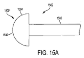
図15A〜15Cは、他の例のカテーテルガイドチップ1500の異なる図である。カテーテルガイドチップ1500は、カテーテル結合部分1508の遠位端1506における先端部分1502を含む。先端部分1502は、先端部分1502の最遠位ポイントでの遠位端1506から近位に延伸した半球形状1504である。半球形状1504は、先端部分1502がより簡単に圧縮可能であるように、好ましくは、中空の半球1510である。
15A-15C are different views of another example
前述の実装の説明は、説明の目的のために提供されている。それは、あらゆる形態を含むものでなく、本発明を開示された形態に限定するものではない。本発明は、上述の発明を参照して改変及び変更してもよいし、それらの改変や変更は本発明を実施する際に行われ得る。請求の範囲とその均等物によって本発明の範囲が定められる。 The foregoing implementation description is provided for illustrative purposes. It is not intended to be inclusive of any form and is not intended to limit the invention to the form disclosed. The present invention may be modified and changed with reference to the above-described invention, and those modifications and changes may be made when the present invention is implemented. The scope of the invention is defined by the claims and their equivalents.
100 カテーテルシステム
102 血管内装置
104 カテーテル部材
106 近位ハブ
108 カテーテルガイドチップ
200 カテーテルガイドチップ
202 先端部分
204 カテーテル部材
206 最遠位ポイント
208 移行部分
210 巻回部分
220 開口
222 管腔
300 カテーテルガイドポイント
302 先端部分
303 結合部分
304 移行部分
306 球根状部分
310 内部空間
312 先端部分内部空間
400 カテーテルガイドチップ
402 先端部分
404 球根形状
408 結合部分
412 空間充填物
500 カテーテルガイドチップ
502 先端部分
506 移行部分
508 結合部分
512 先端部分内部空間
600 カテーテルガイドチップ
602 先端部分
604 球根形状
608 結合部分
610 内部空間
612 圧縮性素材
700 カテーテルガイドチップ
702 先端部分
704 球根形状
710 位置合せピン
800 カテーテルガイドチップ
802 結合部分
804 球根形状
806 内部空間
808 先端部分内部空間
810 球根形状フレーム
900 カテーテルガイドチップ
1000 カテーテルガイドチップ
1100 カテーテルガイドチップ
1200 カテーテルガイドチップ
1300 カテーテルガイドチップ
1400 カテーテルガイドチップ
100
Claims (4)
前記カテーテルの外径と実質的に同じ外径を有し、前記カテーテルの遠位端で遠位側に延伸するカテーテルガイドチップを備えており、
前記カテーテルガイドチップは、巻回部分を有する先端部分を有する少なくとも1つのガイド部材まで遠位側に拡大し、
前記先端部分は、非圧縮状態で、前記カテーテルの長軸に直交する少なくとも1つの軸に沿って、前記カテーテル外径よりも大きな形状を有し、
前記巻回部分は、前記先端部分が圧縮されている状態では前記先端部分よりも大きく且つ前記先端部分が圧縮されていない状態では前記先端部分よりも小さいシースに挿入されるように変形可能であって、圧縮力を受けていない状態では前記圧縮されていない形状に回復するための弾性を有し、
前記先端部分の前記巻回部分の非圧縮状態での形状は、前記カテーテルの長軸に直角な軸に沿った実質的な釣り針状部材を形成するように放射状に且つ遠位側に延伸する部材として形成され、
前記先端部分は、移行部分において前記巻回部分へ移行し、前記巻回部分は、前記先端部分が前記先端部分の最遠位ポイントまで釣り針状に湾曲しながら平坦化された中実の断面を有し、前記先端部分は、前記カテーテル部材へ前記先端部分を取り付けるための前記カテーテル部材の管腔にはめ込まれる狭い部分を含む、
ことを特徴とする、患者の血管の中へカテーテル部材をガイドする装置。 A device for guiding a catheter member into a blood vessel of a patient,
A catheter guide tip having an outer diameter substantially the same as the outer diameter of the catheter and extending distally at the distal end of the catheter;
The catheter guide tip extends distally to at least one guide member having a tip portion having a winding portion ;
The distal portion has a shape larger than the outer diameter of the catheter along at least one axis orthogonal to the long axis of the catheter in an uncompressed state;
The wound portion is deformable so as to be inserted into a sheath that is larger than the tip portion when the tip portion is compressed and smaller than the tip portion when the tip portion is not compressed. And having elasticity to recover to the uncompressed shape in a state where it is not subjected to compression force,
An uncompressed shape of the wound portion of the tip portion is a member that extends radially and distally to form a substantially fishhook-like member along an axis perpendicular to the long axis of the catheter. Formed as
The tip portion transitions to the winding portion at the transition portion, and the winding portion has a solid cross-section that is flattened while the tip portion curves in a fishhook shape to the most distal point of the tip portion. The tip portion includes a narrow portion that fits into a lumen of the catheter member for attaching the tip portion to the catheter member;
And wherein the apparatus for guiding the catheter member into a patient's blood vessel.
前記先端部分の最遠位ポイントが、前記移行部分の近くに配置されている、請求項1の装置。 The winding part is bent like a fishhook,
The apparatus of claim 1, wherein a distal most point of the tip portion is disposed proximate to the transition portion .
前記先端部分の最遠位ポイントが、前記カテーテルが径方向に伸びて前記巻回部分を形成し始める前記移行部分の遠位側に配置されている、請求項1の装置。 The winding portion is bent fishing Ri needle toward the tip portion inward,
The distal-most point of the tip portion, the catheter is disposed distally of the transition portion extending radially begin to form the winding portion, apparatus according to claim 1.
Applications Claiming Priority (3)
| Application Number | Priority Date | Filing Date | Title |
|---|---|---|---|
| US201462010297P | 2014-06-10 | 2014-06-10 | |
| US62/010,297 | 2014-06-10 | ||
| PCT/US2015/035061 WO2015191685A1 (en) | 2014-06-10 | 2015-06-10 | Conduit guiding tip |
Publications (2)
| Publication Number | Publication Date |
|---|---|
| JP2017506932A JP2017506932A (en) | 2017-03-16 |
| JP6286564B2 true JP6286564B2 (en) | 2018-02-28 |
Family
ID=54834233
Family Applications (1)
| Application Number | Title | Priority Date | Filing Date |
|---|---|---|---|
| JP2016546035A Active JP6286564B2 (en) | 2014-06-10 | 2015-06-10 | Conduit guide tip |
Country Status (7)
| Country | Link |
|---|---|
| US (1) | US10232142B2 (en) |
| EP (1) | EP3077036A4 (en) |
| JP (1) | JP6286564B2 (en) |
| AU (1) | AU2015274743B2 (en) |
| CA (1) | CA2941438C (en) |
| IL (1) | IL246670A0 (en) |
| WO (1) | WO2015191685A1 (en) |
Cited By (3)
| Publication number | Priority date | Publication date | Assignee | Title |
|---|---|---|---|---|
| US11596411B2 (en) | 2017-04-21 | 2023-03-07 | The Regents Of The University Of California | Aortic flow meter and pump for partial-aortic occlusion |
| US11602592B2 (en) | 2017-01-12 | 2023-03-14 | The Regents Of The University Of California | Endovascular perfusion augmentation for critical care |
| US11633192B2 (en) | 2020-03-16 | 2023-04-25 | Certus Critical Care, Inc. | Blood flow control devices, systems, and methods |
Families Citing this family (11)
| Publication number | Priority date | Publication date | Assignee | Title |
|---|---|---|---|---|
| CA2797237C (en) | 2010-04-21 | 2018-05-22 | The Regents Of The University Of Michigan | Fluoroscopy-independent, endovascular aortic occlusion system |
| US9474882B2 (en) | 2013-02-26 | 2016-10-25 | Prytime Medical Devices, Inc. | Fluoroscopy-independent balloon guided occlusion catheter and methods |
| WO2015035393A1 (en) | 2013-09-09 | 2015-03-12 | Pryor Medical Devices, Inc. | Low-profile occlusion catheter |
| JP6286564B2 (en) | 2014-06-10 | 2018-02-28 | プリタイム・メディカル・デバイシーズ・インコーポレイテッドPrytime Medical Devices,Inc. | Conduit guide tip |
| US10279094B2 (en) | 2015-01-21 | 2019-05-07 | United States Of America As Represented By The Secretary Of The Air Force | Endovascular variable aortic control catheter |
| CA2980018C (en) | 2015-03-19 | 2018-02-20 | Prytime Medical Devices, Inc. | System and method for low-profile occlusion balloon catheter |
| WO2017165298A1 (en) | 2016-03-22 | 2017-09-28 | Government Of The United States, As Represented By The Secretary Of The Air Force | Vascular access disassembling needle device and method |
| CA2990479C (en) | 2016-06-02 | 2019-03-26 | Prytime Medical Devices, Inc. | System and method for low-profile occlusion balloon catheter |
| AU2017204183A1 (en) | 2016-06-22 | 2018-01-18 | Prytime Medical Devices, Inc. | Handheld Multi-Needle Vascular Access Device |
| WO2020033372A1 (en) | 2018-08-06 | 2020-02-13 | Prytime Medical Devices, Inc. | System and method for low profile occlusion balloon catheter |
| US12102330B2 (en) | 2021-03-18 | 2024-10-01 | Prytime Medical Devices, Inc. | Vascular occlusion catheter for partial occlusion or full occlusion |
Family Cites Families (155)
| Publication number | Priority date | Publication date | Assignee | Title |
|---|---|---|---|---|
| US2156289A (en) | 1937-04-13 | 1939-05-02 | Permochart Corp | Record chart for automatic recording instruments |
| US4370983A (en) | 1971-01-20 | 1983-02-01 | Lichtenstein Eric Stefan | Computer-control medical care system |
| US4823469A (en) | 1986-09-23 | 1989-04-25 | Broselow James B | Measuring tape for directly determining physical treatment and physiological values and procedures |
| US4713888A (en) | 1985-10-21 | 1987-12-22 | Broselow James B | Measuring tape for directly determining physical treatment and physiological values |
| US4777951A (en) | 1986-09-19 | 1988-10-18 | Mansfield Scientific, Inc. | Procedure and catheter instrument for treating patients for aortic stenosis |
| US5273042A (en) | 1987-10-28 | 1993-12-28 | Medical Parameters, Inc. | Guidewire advancement method |
| JPH01171571A (en) | 1987-12-28 | 1989-07-06 | Yoshiharu Yamawaki | Balloon catheter |
| US4926885A (en) | 1988-02-22 | 1990-05-22 | Hinkle Allen J | Method of selecting medication and medical equipment |
| US4865549A (en) | 1988-04-14 | 1989-09-12 | Kristicare, Inc. | Medical documentation and assessment apparatus |
| US5135494A (en) | 1988-08-01 | 1992-08-04 | Target Therapeutics | Valved catheter device and method |
| US5169386A (en) | 1989-09-11 | 1992-12-08 | Bruce B. Becker | Method and catheter for dilatation of the lacrimal system |
| JP2875315B2 (en) * | 1989-12-27 | 1999-03-31 | テルモ株式会社 | Angiographic catheter |
| WO1992020398A1 (en) | 1991-05-23 | 1992-11-26 | Leocor, Inc. | Perfusion catheter |
| US5558644A (en) | 1991-07-16 | 1996-09-24 | Heartport, Inc. | Retrograde delivery catheter and method for inducing cardioplegic arrest |
| US5447503A (en) | 1991-08-14 | 1995-09-05 | Cordis Corporation | Guiding catheter tip having a tapered tip with an expandable lumen |
| US5505702A (en) | 1992-04-09 | 1996-04-09 | Scimed Life Systems, Inc. | Balloon catheter for dilatation and perfusion |
| US5282479A (en) | 1992-10-13 | 1994-02-01 | Boc Health Care, Inc. | Guidewire introducer with guidewire grasp and release means |
| US5320605A (en) | 1993-01-22 | 1994-06-14 | Harvinder Sahota | Multi-wire multi-balloon catheter |
| US5383856A (en) | 1993-03-19 | 1995-01-24 | Bersin; Robert M. | Helical spiral balloon catheter |
| JP3619845B2 (en) | 1994-09-02 | 2005-02-16 | ヴォルケーノ・セラピューテックス・インコーポレイテッド | Guide wire using micro pressure sensor |
| US5571093A (en) | 1994-09-21 | 1996-11-05 | Cruz; Cosme | Multiple-lumen catheter |
| US5522400A (en) | 1994-11-23 | 1996-06-04 | Uresil Corp | Locking catheter system |
| GB9501424D0 (en) * | 1995-01-25 | 1995-03-15 | Carrie Len | Epidural catheter |
| AU7165896A (en) * | 1995-10-10 | 1997-04-30 | Cardiac Pathways Corporation | Shape control of catheters by use of movable inner tube |
| SE9601541D0 (en) | 1995-11-08 | 1996-04-23 | Pacesetter Ab | Guidewire assembly |
| US5718678A (en) | 1996-06-26 | 1998-02-17 | Medical Components, Inc. | Multi-lumen coaxial catheter and method for making same |
| US6652546B1 (en) | 1996-07-26 | 2003-11-25 | Kensey Nash Corporation | System and method of use for revascularizing stenotic bypass grafts and other occluded blood vessels |
| JP3527378B2 (en) * | 1997-01-31 | 2004-05-17 | テルモ株式会社 | Contrast catheter |
| US5830181A (en) | 1997-02-07 | 1998-11-03 | Advanced Cardiovascular Systems, Inc. | Perfusion catheter with high flow distal tip |
| US6217549B1 (en) * | 1997-02-28 | 2001-04-17 | Lumend, Inc. | Methods and apparatus for treating vascular occlusions |
| US5755687A (en) | 1997-04-01 | 1998-05-26 | Heartport, Inc. | Methods and devices for occluding a patient's ascending aorta |
| US6102930A (en) | 1997-05-16 | 2000-08-15 | Simmons, Jr.; Edward D. | Volumetric measurement device and method in lateral recess and foraminal spinal stenosis |
| DE19739086C1 (en) | 1997-09-06 | 1999-07-15 | Voelker Wolfram Priv Doz Dr Me | Balloon catheter |
| US6656153B1 (en) | 1997-09-12 | 2003-12-02 | Nippon Zeon Co., Ltd | Balloon catheter |
| WO1999020324A1 (en) | 1997-10-20 | 1999-04-29 | Bersin Robert D | Helical spiral balloon catheter |
| US5911702A (en) | 1997-11-06 | 1999-06-15 | Heartport, Inc. | Methods and devices for cannulating a patient's blood vessel |
| US6013085A (en) | 1997-11-07 | 2000-01-11 | Howard; John | Method for treating stenosis of the carotid artery |
| US6248121B1 (en) | 1998-02-18 | 2001-06-19 | Cardio Medical Solutions, Inc. | Blood vessel occlusion device |
| US6736790B2 (en) | 1998-02-25 | 2004-05-18 | Denise R. Barbut | Method and system for selective or isolated integrate cerebral perfusion and cooling |
| US6517515B1 (en) | 1998-03-04 | 2003-02-11 | Scimed Life Systems, Inc. | Catheter having variable size guide wire lumen |
| US6113579A (en) | 1998-03-04 | 2000-09-05 | Scimed Life Systems, Inc. | Catheter tip designs and methods for improved stent crossing |
| US6013019A (en) | 1998-04-06 | 2000-01-11 | Isostent, Inc. | Temporary radioisotope stent |
| US20010001113A1 (en) | 1998-04-21 | 2001-05-10 | Florencia Lim | Balloon catheter |
| US6231572B1 (en) | 1998-05-29 | 2001-05-15 | Applied Medical Resources Corporation | Electrosurgical catheter apparatus and method |
| AU5333599A (en) | 1998-08-06 | 2000-02-28 | Cardeon Corporation | Aortic catheter with porous aortic arch balloon and methods for selective aorticperfusion |
| US6735532B2 (en) | 1998-09-30 | 2004-05-11 | L. Vad Technology, Inc. | Cardiovascular support control system |
| US6165199A (en) | 1999-01-12 | 2000-12-26 | Coaxia, Inc. | Medical device for removing thromboembolic material from cerebral arteries and methods of use |
| US6161547A (en) | 1999-01-15 | 2000-12-19 | Coaxia, Inc. | Medical device for flow augmentation in patients with occlusive cerebrovascular disease and methods of use |
| US6743196B2 (en) | 1999-03-01 | 2004-06-01 | Coaxia, Inc. | Partial aortic occlusion devices and methods for cerebral perfusion augmentation |
| US6146370A (en) | 1999-04-07 | 2000-11-14 | Coaxia, Inc. | Devices and methods for preventing distal embolization from the internal carotid artery using flow reversal by partial occlusion of the external carotid artery |
| US6190304B1 (en) | 1999-07-13 | 2001-02-20 | University Of North Texas Health Science Center At Fort Worth | Enhanced intra-aortic balloon assist device |
| US6679861B2 (en) | 1999-10-04 | 2004-01-20 | K.K. Vayu | Occlusion catheter for the ascending aorta |
| US6733513B2 (en) | 1999-11-04 | 2004-05-11 | Advanced Bioprosthetic Surfaces, Ltd. | Balloon catheter having metal balloon and method of making same |
| US6575932B1 (en) | 1999-12-02 | 2003-06-10 | Ottawa Heart Institute | Adjustable multi-balloon local delivery device |
| US6733486B1 (en) | 1999-12-22 | 2004-05-11 | Advanced Cardiovascular Systems, Inc. | Catheter having a reinforcing mandrel |
| US6669679B1 (en) * | 2000-01-07 | 2003-12-30 | Acist Medical Systems, Inc. | Anti-recoil catheter |
| US6663613B1 (en) | 2000-01-25 | 2003-12-16 | Bacchus Vascular, Inc. | System and methods for clot dissolution |
| US6453572B2 (en) | 2000-02-22 | 2002-09-24 | Cross-Tek, Llc | Floor covering estimating device |
| WO2001097743A2 (en) | 2000-06-16 | 2001-12-27 | Abbott Laboratories | Balloon occlusion device having a proximal valve |
| US7094216B2 (en) | 2000-10-18 | 2006-08-22 | Medrad, Inc. | Injection system having a pressure isolation mechanism and/or a handheld controller |
| JP4522568B2 (en) | 2000-10-26 | 2010-08-11 | サーパス工業株式会社 | Plug for fluid pipe connector |
| ATE387927T1 (en) | 2000-12-12 | 2008-03-15 | Datascope Investment Corp | INTRA-AORTAL BALLOON CATHETER WITH FIBER-OPTICAL SENSOR |
| US6796959B2 (en) | 2001-03-19 | 2004-09-28 | Atrion Medical Products, Inc. | Actuating mechanism for fluid displacement and pressurizing device |
| US6579221B1 (en) | 2001-05-31 | 2003-06-17 | Advanced Cardiovascular Systems, Inc. | Proximal catheter shaft design and catheters incorporating the proximal shaft design |
| US8741335B2 (en) | 2002-06-14 | 2014-06-03 | Hemcon Medical Technologies, Inc. | Hemostatic compositions, assemblies, systems, and methods employing particulate hemostatic agents formed from hydrophilic polymer foam such as Chitosan |
| US6679860B2 (en) | 2001-06-19 | 2004-01-20 | Medtronic Ave, Inc. | Intraluminal therapy catheter with inflatable helical member and methods of use |
| US6602270B2 (en) | 2001-08-13 | 2003-08-05 | Datascope Investment Corp. | Reduced size intra-aortic balloon catheter |
| US6800068B1 (en) | 2001-10-26 | 2004-10-05 | Radiant Medical, Inc. | Intra-aortic balloon counterpulsation with concurrent hypothermia |
| JP3922910B2 (en) | 2001-10-31 | 2007-05-30 | 参天製薬株式会社 | Eye drops container with stepped part |
| US7503904B2 (en) | 2002-04-25 | 2009-03-17 | Cardiac Pacemakers, Inc. | Dual balloon telescoping guiding catheter |
| US20040073162A1 (en) | 2002-05-29 | 2004-04-15 | Bleam Jefferey C. | Balloon construction for occlusion device |
| US6979318B1 (en) | 2002-10-07 | 2005-12-27 | Lemaitre Vascular, Inc. | Catheter introducer |
| CN100581612C (en) | 2002-12-04 | 2010-01-20 | 湖区制造公司 | Marked guidewires |
| US7763043B2 (en) | 2003-01-09 | 2010-07-27 | Boston Scientific Scimed, Inc. | Dilatation catheter with enhanced distal end for crossing occluded lesions |
| US8252019B2 (en) | 2003-01-31 | 2012-08-28 | Cordis Corporation | Filter retrieval catheter system, and methods |
| JP4192040B2 (en) | 2003-06-11 | 2008-12-03 | 泉工医科工業株式会社 | Balloon pump drive device |
| US20040254528A1 (en) | 2003-06-12 | 2004-12-16 | Adams Daniel O. | Catheter with removable wire lumen segment |
| US7744620B2 (en) | 2003-07-18 | 2010-06-29 | Intervalve, Inc. | Valvuloplasty catheter |
| DE10336902C5 (en) | 2003-08-08 | 2019-04-25 | Abiomed Europe Gmbh | Intracardiac pumping device |
| EP1658111B1 (en) | 2003-08-29 | 2018-09-19 | Datascope Investment Corp. | Timing of intra-aortic balloon pump therapy |
| US20050059931A1 (en) | 2003-09-16 | 2005-03-17 | Venomatrix | Methods and apparatus for localized and semi-localized drug delivery |
| JP2007528237A (en) | 2003-11-28 | 2007-10-11 | クック・インコーポレーテッド | Vessel occlusion method, system and apparatus |
| US7220230B2 (en) | 2003-12-05 | 2007-05-22 | Edwards Lifesciences Corporation | Pressure-based system and method for determining cardiac stroke volume |
| US7803150B2 (en) | 2004-04-21 | 2010-09-28 | Acclarent, Inc. | Devices, systems and methods useable for treating sinusitis |
| EP1787576A1 (en) | 2004-08-03 | 2007-05-23 | Olympus Corporation | Resin composition for medical equipment sealing and medical equipment for endoscope having been sealed therewith |
| US7341571B1 (en) | 2004-09-02 | 2008-03-11 | Advanced Cardiovascular Systems, Inc. | Balloon catheter having a multilayered distal tip |
| WO2006042157A1 (en) | 2004-10-06 | 2006-04-20 | Cook Incorporated | A flexible tip |
| CA2596538C (en) | 2005-02-02 | 2014-09-23 | Medical Components, Inc. | Guide wire advancer assembly |
| US20080262467A1 (en) | 2005-02-16 | 2008-10-23 | Humphrey Joseph A C | Blood Flow Bypass Catheters and Methods for the Delivery of Medium to the Vasculature and Body Ducts |
| US20060253099A1 (en) * | 2005-04-21 | 2006-11-09 | Medtronic Vascular, Inc. | Guiding catheter with resiliently compressible occluder |
| US7434326B2 (en) | 2005-05-25 | 2008-10-14 | Edward Gifford | Precision box jig |
| US8285011B2 (en) | 2005-06-02 | 2012-10-09 | M2S | Anatomical visualization and measurement system |
| US7515957B2 (en) | 2005-06-23 | 2009-04-07 | Medtronic Vascular, Inc. | Catheter-based, dual balloon photopolymerization system |
| ES2670822T3 (en) | 2005-06-29 | 2018-06-01 | Zoll Circulation, Inc. | Devices and systems for rapid endovascular cooling |
| EP1917054A4 (en) | 2005-08-25 | 2010-12-22 | Osprey Medical Inc | Devices and methods for perfusing an organ |
| US20070219488A1 (en) | 2005-12-16 | 2007-09-20 | Darius Francescatti | Active drainage system for use in defined natural or surgically created body cavities or lumina |
| US8961532B2 (en) | 2006-01-06 | 2015-02-24 | Bayer Essure Inc. | Atraumatic catheter tip |
| US7740609B2 (en) | 2006-03-03 | 2010-06-22 | Boston Scientific Scimed, Inc. | Balloon catheter |
| US7951186B2 (en) | 2006-04-25 | 2011-05-31 | Boston Scientific Scimed, Inc. | Embedded electroactive polymer structures for use in medical devices |
| US7951819B2 (en) | 2006-04-26 | 2011-05-31 | Cancer Research Technology Limited | Imidazo[4, 5-B]pyridin-2-one and oxazolo[4, 5-B] pyridin-2-one compounds and analogs thereof as cancer therapeutic compounds |
| US8486025B2 (en) | 2006-05-11 | 2013-07-16 | Ronald J. Solar | Systems and methods for treating a vessel using focused force |
| US8114031B2 (en) | 2006-07-26 | 2012-02-14 | Johan Willem Pieter Marsman | Facilitation of antegrade insertion of a guidewire into the superficial femoral artery |
| US8679025B2 (en) | 2006-08-31 | 2014-03-25 | Atcor Medical Pty Ltd | Method for determination of cardiac output |
| JP4562197B2 (en) | 2006-09-29 | 2010-10-13 | 朝日インテック株式会社 | Balloon catheter assembly |
| US20080082119A1 (en) | 2006-10-03 | 2008-04-03 | Vitullo Jeffrey M | Method of determining an appropriate catheter length |
| DE102007007198A1 (en) | 2007-02-09 | 2008-08-14 | Maquet Cardiopulmonary Ag | Method and device for monitoring and optimizing a blood circulation caused by a pump |
| US8257383B2 (en) | 2007-03-29 | 2012-09-04 | Boston Scientific Limited | Lumen reentry devices and methods |
| US8900214B2 (en) | 2007-03-30 | 2014-12-02 | Onset Medical Corporation | Expandable trans-septal sheath |
| US20080262477A1 (en) | 2007-04-20 | 2008-10-23 | Dr. Hooman Djaladat | Hand made catheter to be used in suprapubic prostatectomy |
| JP2009032906A (en) | 2007-07-27 | 2009-02-12 | Seiko Instruments Inc | Semiconductor device package |
| US9687333B2 (en) | 2007-08-31 | 2017-06-27 | BiO2 Medical, Inc. | Reduced profile central venous access catheter with vena cava filter and method |
| WO2009053839A2 (en) | 2007-10-22 | 2009-04-30 | Endocross Ltd. | Balloons and balloon catheter systems for treating vascular occlusions |
| US20090171293A1 (en) | 2007-12-28 | 2009-07-02 | Wilson-Cook Medical Inc. | Self expanding wire guide |
| US20090171272A1 (en) | 2007-12-29 | 2009-07-02 | Tegg Troy T | Deflectable sheath and catheter assembly |
| CA2650703C (en) | 2008-01-23 | 2016-10-04 | Mediguide Ltd. | Sensor mounted flexible guidewire |
| US7631439B2 (en) | 2008-04-28 | 2009-12-15 | Bryan Joseph Black | Reference chart apparatus |
| US7959644B2 (en) | 2008-05-16 | 2011-06-14 | Edgar L Shriver | Hemostatic guiding catheter |
| JP2011524209A (en) | 2008-06-13 | 2011-09-01 | ピボット・メディカル,インコーポレーテッド | Method and apparatus for joint distraction |
| US20100041984A1 (en) | 2008-08-12 | 2010-02-18 | James Edward Shapland | Impedance sensing device and catheter system |
| US8162879B2 (en) | 2008-09-22 | 2012-04-24 | Tyco Healthcare Group Lp | Double balloon catheter and methods for homogeneous drug delivery using the same |
| WO2010062778A2 (en) | 2008-11-03 | 2010-06-03 | Atlanta Catheter Therapies, Inc. | Occlusion perfusion catheter |
| US8499681B2 (en) | 2008-11-13 | 2013-08-06 | Atrion Medical Products, Inc. | Actuating mechanism for fluid displacement and pressurizing device |
| EP2376170B1 (en) * | 2008-12-18 | 2019-07-17 | Invatec S.p.A. | Guide catheter |
| US20120109057A1 (en) | 2009-02-18 | 2012-05-03 | Hotspur Technologies, Inc. | Apparatus and methods for treating obstructions within body lumens |
| EP2716323A1 (en) | 2009-03-09 | 2014-04-09 | Flip Technologies Limited | Apparatus for monitoring the internal transverse cross-section of a stoma in a stomach |
| US20100234915A1 (en) | 2009-03-11 | 2010-09-16 | Herlich Michael B | Non-bioelectrical pressure-based sensing for temporary pacemakers |
| GB2469073A (en) | 2009-03-31 | 2010-10-06 | Barking Havering And Redbridge | Balloon Assisted Occlusion of Aneurysms |
| US9522215B2 (en) | 2011-08-12 | 2016-12-20 | Arsenal Medical, Inc. | Intra-abdominal pressure to promote hemostasis and survival |
| CA2797237C (en) | 2010-04-21 | 2018-05-22 | The Regents Of The University Of Michigan | Fluoroscopy-independent, endovascular aortic occlusion system |
| US11337707B2 (en) | 2010-05-25 | 2022-05-24 | Miracor Medical Sa | Treating heart tissue |
| EP2389974B1 (en) | 2010-05-25 | 2014-04-23 | Miracor Medical Systems GmbH | A balloon catheter for introduction into a body vessel, in particular the coronary sinus |
| US10743780B2 (en) | 2010-05-25 | 2020-08-18 | Miracor Medical Sa | Catheter system and method for occluding a body vessel |
| US20110301630A1 (en) | 2010-06-02 | 2011-12-08 | Cook Incorporated | Occlusion device |
| TW201221165A (en) | 2010-10-20 | 2012-06-01 | Medtronic Ardian Luxembourg | Catheter apparatuses having expandable mesh structures for renal neuromodulation and associated systems and methods |
| US20120136344A1 (en) | 2010-10-26 | 2012-05-31 | Medtronic Ardian Luxembourg S.A.R.L. | Neuromodulation cryotherapeutic devices and associated systems and methods |
| AU2011319740B9 (en) | 2010-10-27 | 2015-09-24 | W. L. Gore & Associates, Inc. | Imaging catheter with rotatble array |
| US20120172911A1 (en) | 2010-12-30 | 2012-07-05 | Cook Medical Technologies Llc | Occlusion device |
| US8948848B2 (en) | 2011-01-07 | 2015-02-03 | Innovative Cardiovascular Solutions, Llc | Angiography catheter |
| EP2478929B1 (en) | 2011-01-25 | 2018-08-01 | Karl Storz SE & Co. KG | Balloon catheter with metal shaft |
| US20120271231A1 (en) | 2011-04-25 | 2012-10-25 | Sony Agrawal | Aspiration thrombectomy device |
| US10406329B2 (en) | 2011-05-26 | 2019-09-10 | Abbott Cardiovascular Systems, Inc. | Through tip for catheter |
| US9808356B2 (en) | 2011-10-24 | 2017-11-07 | Synvasive Technology, Inc. | Knee balancing devices, systems and methods |
| US20130190619A1 (en) | 2011-12-06 | 2013-07-25 | Ron Nudel | Angiography Catheter |
| US10653423B2 (en) | 2012-06-29 | 2020-05-19 | University Of Washington | Catheters for emergency endovascular surgery and associated devices, systems, and methods |
| US9440045B2 (en) | 2013-02-01 | 2016-09-13 | Cook Medical Technologies Llc | Curved tip hemodialysis catheter |
| JP6345192B2 (en) | 2013-02-26 | 2018-06-20 | プリタイム・メディカル・デバイシーズ・インコーポレイテッドPrytime Medical Devices,Inc. | Vascular access system |
| US9474882B2 (en) | 2013-02-26 | 2016-10-25 | Prytime Medical Devices, Inc. | Fluoroscopy-independent balloon guided occlusion catheter and methods |
| JP6419773B2 (en) | 2013-03-15 | 2018-11-07 | キューエックスメディカル リミテッド ライアビリティ カンパニー | Boosting catheter and related systems and methods |
| US20140316012A1 (en) | 2013-03-15 | 2014-10-23 | Toby Freyman | In-Situ Forming Foams for Embolizing or Occluding a Cavity |
| CA2917653A1 (en) | 2013-07-17 | 2015-01-22 | Hibernation Therapeutics, A Kf Llc | A method for treating infection, sepsis and injury |
| WO2015035393A1 (en) * | 2013-09-09 | 2015-03-12 | Pryor Medical Devices, Inc. | Low-profile occlusion catheter |
| JP6286564B2 (en) | 2014-06-10 | 2018-02-28 | プリタイム・メディカル・デバイシーズ・インコーポレイテッドPrytime Medical Devices,Inc. | Conduit guide tip |
| GB2528639B (en) | 2014-06-23 | 2016-08-17 | Cook Medical Technologies Llc | Catheter or sheath assembly |
| USD748257S1 (en) | 2014-10-24 | 2016-01-26 | Pryor Medical Devices, Inc. | Guiding catheter tip |
| CA2980018C (en) | 2015-03-19 | 2018-02-20 | Prytime Medical Devices, Inc. | System and method for low-profile occlusion balloon catheter |
-
2015
- 2015-06-10 JP JP2016546035A patent/JP6286564B2/en active Active
- 2015-06-10 AU AU2015274743A patent/AU2015274743B2/en active Active
- 2015-06-10 US US15/306,540 patent/US10232142B2/en active Active
- 2015-06-10 EP EP15806534.2A patent/EP3077036A4/en not_active Withdrawn
- 2015-06-10 CA CA2941438A patent/CA2941438C/en active Active
- 2015-06-10 WO PCT/US2015/035061 patent/WO2015191685A1/en active Application Filing
-
2016
- 2016-07-07 IL IL246670A patent/IL246670A0/en unknown
Cited By (4)
| Publication number | Priority date | Publication date | Assignee | Title |
|---|---|---|---|---|
| US11602592B2 (en) | 2017-01-12 | 2023-03-14 | The Regents Of The University Of California | Endovascular perfusion augmentation for critical care |
| US11596411B2 (en) | 2017-04-21 | 2023-03-07 | The Regents Of The University Of California | Aortic flow meter and pump for partial-aortic occlusion |
| US11633192B2 (en) | 2020-03-16 | 2023-04-25 | Certus Critical Care, Inc. | Blood flow control devices, systems, and methods |
| US12251111B2 (en) | 2020-03-16 | 2025-03-18 | Certus Critical Care, Inc. | Blood flow control devices, systems, and methods |
Also Published As
| Publication number | Publication date |
|---|---|
| IL246670A0 (en) | 2016-08-31 |
| CA2941438C (en) | 2018-04-10 |
| US20170043123A1 (en) | 2017-02-16 |
| US10232142B2 (en) | 2019-03-19 |
| WO2015191685A1 (en) | 2015-12-17 |
| AU2015274743B2 (en) | 2016-11-10 |
| CA2941438A1 (en) | 2015-12-17 |
| AU2015274743A1 (en) | 2016-09-01 |
| JP2017506932A (en) | 2017-03-16 |
| EP3077036A1 (en) | 2016-10-12 |
| EP3077036A4 (en) | 2017-04-19 |
Similar Documents
| Publication | Publication Date | Title |
|---|---|---|
| JP6286564B2 (en) | Conduit guide tip | |
| JP6343009B2 (en) | Low profile occlusion catheter | |
| JP5564416B2 (en) | Lumen reentry device | |
| US20200246036A1 (en) | Internal carotid artery thrombectomy devices and methods | |
| US6508824B1 (en) | Catheter-based methods for enlarging blood vessels to facilitate the formation of penetration tracts, fistulas and/or blood flow channels | |
| US20160144155A1 (en) | Occlusion sheath for imaging catheter | |
| BRPI0611054A2 (en) | system for controlled release of stents and grafts | |
| JP3533299B2 (en) | Nickel-titanium slip medical catheter wire | |
| US9326790B2 (en) | Catheter with vessel lining and methods for using same | |
| US20180036158A1 (en) | Medical-device position adjusting method and medical device system | |
| CN106794333B (en) | Catheter system and method for re-entering a body vessel having a chronic total occlusion lesion | |
| CN103316416B (en) | Ball head guide wire | |
| WO2019042454A1 (en) | Coronary vein guide system and guide method thereof | |
| CN114206423A (en) | Conduit clamping device | |
| US12102478B2 (en) | User-attachable/detachable imaging catheter | |
| US12059158B2 (en) | Expandable-mouth catheter delivery-assist tool | |
| CN118542982A (en) | Extended suction catheter and catheter system having the same | |
| CN112823818A (en) | Isolated endovascular therapy with perfusion bypass | |
| JP2007202614A (en) | Catheter | |
| JP2003079739A (en) | Dilation balloon catheter | |
| CN107920823A (en) | Dismountable implantable device | |
| JP2006175246A (en) | Balloon catheter |
Legal Events
| Date | Code | Title | Description |
|---|---|---|---|
| A524 | Written submission of copy of amendment under article 19 pct |
Free format text: JAPANESE INTERMEDIATE CODE: A525 Effective date: 20160831 |
|
| A621 | Written request for application examination |
Free format text: JAPANESE INTERMEDIATE CODE: A621 Effective date: 20160831 |
|
| A871 | Explanation of circumstances concerning accelerated examination |
Free format text: JAPANESE INTERMEDIATE CODE: A871 Effective date: 20160831 |
|
| A975 | Report on accelerated examination |
Free format text: JAPANESE INTERMEDIATE CODE: A971005 Effective date: 20170124 |
|
| A131 | Notification of reasons for refusal |
Free format text: JAPANESE INTERMEDIATE CODE: A131 Effective date: 20170411 |
|
| A521 | Request for written amendment filed |
Free format text: JAPANESE INTERMEDIATE CODE: A523 Effective date: 20170609 |
|
| A131 | Notification of reasons for refusal |
Free format text: JAPANESE INTERMEDIATE CODE: A131 Effective date: 20170912 |
|
| A521 | Request for written amendment filed |
Free format text: JAPANESE INTERMEDIATE CODE: A523 Effective date: 20171010 |
|
| A521 | Request for written amendment filed |
Free format text: JAPANESE INTERMEDIATE CODE: A523 Effective date: 20171020 |
|
| TRDD | Decision of grant or rejection written | ||
| A01 | Written decision to grant a patent or to grant a registration (utility model) |
Free format text: JAPANESE INTERMEDIATE CODE: A01 Effective date: 20180123 |
|
| A61 | First payment of annual fees (during grant procedure) |
Free format text: JAPANESE INTERMEDIATE CODE: A61 Effective date: 20180205 |
|
| R150 | Certificate of patent or registration of utility model |
Ref document number: 6286564 Country of ref document: JP Free format text: JAPANESE INTERMEDIATE CODE: R150 |
|
| R250 | Receipt of annual fees |
Free format text: JAPANESE INTERMEDIATE CODE: R250 |
|
| R250 | Receipt of annual fees |
Free format text: JAPANESE INTERMEDIATE CODE: R250 |
|
| R250 | Receipt of annual fees |
Free format text: JAPANESE INTERMEDIATE CODE: R250 |
|
| R250 | Receipt of annual fees |
Free format text: JAPANESE INTERMEDIATE CODE: R250 |
|
| R250 | Receipt of annual fees |
Free format text: JAPANESE INTERMEDIATE CODE: R250 |