[go: up one dir, main page]

JP6172602B2 - Sink with washing tank - Google Patents

Sink with washing tank Download PDF

Info

Publication number
JP6172602B2
JP6172602B2 JP2013124851A JP2013124851A JP6172602B2 JP 6172602 B2 JP6172602 B2 JP 6172602B2 JP 2013124851 A JP2013124851 A JP 2013124851A JP 2013124851 A JP2013124851 A JP 2013124851A JP 6172602 B2 JP6172602 B2 JP 6172602B2
Authority
JP
Japan
Prior art keywords
hole
sink
cleaning
lid
cleaning tank
Prior art date
Legal status (The legal status is an assumption and is not a legal conclusion. Google has not performed a legal analysis and makes no representation as to the accuracy of the status listed.)
Active
Application number
JP2013124851A
Other languages
Japanese (ja)
Other versions
JP2015000128A (en
Inventor
佐藤 靖史
靖史 佐藤
Current Assignee (The listed assignees may be inaccurate. Google has not performed a legal analysis and makes no representation or warranty as to the accuracy of the list.)
Panasonic Intellectual Property Management Co Ltd
Original Assignee
Panasonic Intellectual Property Management Co Ltd
Priority date (The priority date is an assumption and is not a legal conclusion. Google has not performed a legal analysis and makes no representation as to the accuracy of the date listed.)
Filing date
Publication date
Application filed by Panasonic Intellectual Property Management Co Ltd filed Critical Panasonic Intellectual Property Management Co Ltd
Priority to JP2013124851A priority Critical patent/JP6172602B2/en
Publication of JP2015000128A publication Critical patent/JP2015000128A/en
Application granted granted Critical
Publication of JP6172602B2 publication Critical patent/JP6172602B2/en
Active legal-status Critical Current
Anticipated expiration legal-status Critical

Links

Images

Landscapes

  • Combinations Of Kitchen Furniture (AREA)

Description

本発明は、シンクに隣接するカウンターに洗浄槽が設置された洗浄槽付き流し台に関するものである。   The present invention relates to a sink with a cleaning tank in which a cleaning tank is installed at a counter adjacent to a sink.

特許文献1には、キャビネットに洗浄槽を組み込んだ厨房用洗浄装置が開示されている。この厨房用洗浄装置では、キャビネットの上面であるカウンターに、洗浄槽の開口部が開口している。この洗浄槽の開口部は、非使用時には蓋で閉塞される。   Patent Document 1 discloses a kitchen cleaning apparatus in which a cleaning tank is incorporated in a cabinet. In this kitchen cleaning apparatus, the opening of the cleaning tank is opened in the counter that is the upper surface of the cabinet. The opening of the cleaning tank is closed with a lid when not in use.

特開平9−84733号公開Published Japanese Patent Laid-Open No. 9-84733

上述した特許文献1の厨房洗浄装置では、使用者は、洗浄槽の開口部を閉塞する蓋を開く作業を行なわなければ、洗浄槽を利用することができなかった。   In the above-described kitchen cleaning apparatus of Patent Document 1, the user cannot use the cleaning tank unless the user opens the lid that closes the opening of the cleaning tank.

そこで、本発明は、洗浄槽の口を閉塞する蓋を開く作業をしなくても、洗浄槽を利用することができて、使い勝手の良い洗浄槽付き流し台を提案することを課題とする。   Therefore, an object of the present invention is to propose an easy-to-use sink with a washing tank that can be used without opening a lid that closes the mouth of the washing tank.

上記課題を解決する本発明の洗浄槽付き流し台は、シンクと、前記シンクに隣接するカウンターと、前記カウンターに形成される貫通孔と、この貫通孔に連通する洗浄槽と、前記貫通孔に装着される蓋とを、備え、前記蓋は、前記貫通孔を閉塞し、上方から押圧されたときに弾性変形して前記貫通孔を開くものであり、前記カウンターは、上方に向けて突出する突出部分を前記貫通孔の周囲に有することを特徴とする。 The sink with a washing tank of the present invention that solves the above problems is mounted on a sink, a counter adjacent to the sink, a through hole formed in the counter, a washing tank communicating with the through hole, and the through hole. a lid which is provided with the lid, to close the through-hole state, and are not elastically deformed to open the through hole when pressed from above, the counter protrudes upward A protruding portion is provided around the through hole .

また、前記洗浄槽の内側に向けて紫外線を照射する紫外線照射装置を備えることが好ましい。   Moreover, it is preferable to provide the ultraviolet irradiation device which irradiates an ultraviolet-ray toward the inside of the said washing tank.

本発明の洗浄槽付き流し台では、洗浄槽の口をなす貫通孔を閉塞する蓋に対して、洗浄物を上方から押し当てることで、この蓋を弾性変形させて、洗浄槽の口を開くことができる。すなわち、本発明の洗浄槽付き流し台では、洗浄槽内に洗浄物を挿入するといった作業によって、洗浄槽の口を閉塞する蓋を開くことができ、この作業とは別に、洗浄槽の口を閉塞する蓋を開く作業をしなくても、洗浄槽を利用することができて、使い勝手が良い。   In the sink with a washing tank of the present invention, the washing object is pressed from above against the lid that closes the through hole forming the mouth of the washing tank, thereby elastically deforming the lid and opening the mouth of the washing tank. Can do. That is, in the sink with a cleaning tank of the present invention, the lid for closing the mouth of the cleaning tank can be opened by the operation of inserting the cleaning object into the cleaning tank, and the mouth of the cleaning tank is closed separately from this operation. Even if you do not open the lid, you can use the washing tank and it is easy to use.

(a)は本発明の第一実施形態の洗浄槽付き流し台を示す斜視図であり、(b)は同上の洗浄槽付き流し台の要部を示す断面図である。(a) is a perspective view which shows the sink with a washing tank of 1st embodiment of this invention, (b) is sectional drawing which shows the principal part of the sink with a washing tank same as the above. (a)〜(c)は同上の洗浄槽付き流し台の洗浄槽に洗浄物を出し入れする過程を示す説明図であり、(d)は(b)の状態を上から視た説明図である。(A)-(c) is explanatory drawing which shows the process in which a washing | cleaning material is put in and out of the washing tank of a sink with a washing tank same as the above, (d) is explanatory drawing which looked at the state of (b) from the top. (a)は同上の洗浄槽付き流し台の排水構造を示す断面図であり、(b)は同上の洗浄槽付き流し台の他の排水構造を示す断面図である。(A) is sectional drawing which shows the drainage structure of the sink with a washing tank same as the above, (b) is sectional drawing which shows the other drainage structure of the sink with a washing tank same as the above. (a)は本発明の第二実施形態の洗浄槽付き流し台を示す斜視図であり、(b)は同上の洗浄槽付き流し台の要部を示す断面図である。(a) is a perspective view which shows the sink with a washing tank of 2nd embodiment of this invention, (b) is sectional drawing which shows the principal part of the sink with a washing tank same as the above.

本発明を添付図面に示す実施形態に基づいて説明する。   The present invention will be described based on embodiments shown in the accompanying drawings.

本実施形態の洗浄槽付き流し台は、図1に示すように、シンク1と、シンク1に隣接するカウンター2と、カウンター2に形成される貫通孔3と、この貫通孔3に連通する洗浄槽4と、貫通孔3に装着される蓋5と、を備える。蓋5は、貫通孔3を閉塞し、上方から押圧されたときに弾性変形して貫通孔3を開くものである。本実施形態の洗浄槽付き流し台は、シンク1に水を供給するカラン10と、シンク1及びカウンター2の下方に配される収納庫21とを更に備える。   As shown in FIG. 1, the sink with a cleaning tank of the present embodiment includes a sink 1, a counter 2 adjacent to the sink 1, a through hole 3 formed in the counter 2, and a cleaning tank communicating with the through hole 3. 4 and a lid 5 attached to the through-hole 3. The lid 5 closes the through hole 3 and is elastically deformed to open the through hole 3 when pressed from above. The sink with a washing tank of this embodiment further includes a currant 10 for supplying water to the sink 1 and a storage 21 arranged below the sink 1 and the counter 2.

以下では、図1におけるシンク1に対して貫通孔3が位置する側を右側とし、その反対方向を左側とし、シンク1に対してカラン10が位置する側を後側とし、その反対方向を前側として、各構成について説明を行う。なお、この左右方向及び前後方向に直交する方向が上下方向である。   In the following, the side where the through hole 3 is located with respect to the sink 1 in FIG. 1 is the right side, the opposite direction is the left side, the side where the currant 10 is located with respect to the sink 1 is the rear side, and the opposite direction is the front side. Each configuration will be described as follows. In addition, the direction orthogonal to the left-right direction and the front-rear direction is the up-down direction.

シンク1は、左右方向を長手方向とし、前後方向を短手方向とし、上下方向を深さ方向とする平断面略長方形状の容器である。シンク1は、例えば、ステンレス製である。シンク1は、前壁(図示せず)、後壁11、右壁12、左壁13、底壁14を有する。底壁14に、排水溝15が形成されている。シンク1の底面をなす底壁14の上面は、排水溝15に向けて下り傾斜している。   The sink 1 is a container having a substantially rectangular flat cross section in which the left-right direction is the longitudinal direction, the front-rear direction is the short direction, and the vertical direction is the depth direction. The sink 1 is made of stainless steel, for example. The sink 1 has a front wall (not shown), a rear wall 11, a right wall 12, a left wall 13, and a bottom wall 14. A drainage groove 15 is formed in the bottom wall 14. The upper surface of the bottom wall 14 that forms the bottom surface of the sink 1 is inclined downward toward the drainage groove 15.

排水溝15は、図3(a)に示すように、排水トラップ部18を介して、下水管に連通接続される。排水溝15には、排水溝15に流入する水中のごみを捕獲するフィルタ16が装着される。排水溝15は、有底筒状であり、その底部に排水トラップ部18に連通する排水孔150を有する。本実施形態では、排水溝15の側壁には、洗浄槽4に連通する連通孔151が開口している。   As shown in FIG. 3A, the drainage groove 15 is connected to the sewer pipe via the drainage trap portion 18. The drain groove 15 is equipped with a filter 16 that captures underwater dust flowing into the drain groove 15. The drainage groove 15 has a bottomed cylindrical shape and has a drainage hole 150 communicating with the drainage trap part 18 at the bottom. In the present embodiment, a communication hole 151 communicating with the cleaning tank 4 is opened on the side wall of the drainage groove 15.

フィルタ16は、排水溝15の形状に対応した形状を有する。本実施形態では、フィルタ16は、有底筒状の網体であり、連通孔151に対向する箇所に、開口160が設けられている。   The filter 16 has a shape corresponding to the shape of the drainage groove 15. In the present embodiment, the filter 16 is a bottomed cylindrical net, and an opening 160 is provided at a location facing the communication hole 151.

カラン10は、レバー操作によって給水と止水とが手動で切り替えられるものである。なお、カラン10は、センサーによる検知によって給水と止水とが自動的に切り替えられるものであってもよい。   The currant 10 can be manually switched between water supply and water stop by lever operation. Note that the curan 10 may be automatically switched between water supply and water stoppage by detection by a sensor.

カウンター2は、調理台であり、シンク1の側方に位置する。本実施形態では、カウンター2は、シンク1の右側に位置する。なお、カウンター2の右側には、加熱調理器(図示せず)が配される。   The counter 2 is a cooking table and is located on the side of the sink 1. In the present embodiment, the counter 2 is located on the right side of the sink 1. A cooking device (not shown) is disposed on the right side of the counter 2.

カウンター2のうち、シンク1に隣接する箇所に、貫通孔3が形成されている。貫通孔3は、カウンター2を上下方向に貫通している。貫通孔3は、前後方向を長手方向とし、左右方向を短手方向とする角孔である。   A through hole 3 is formed at a location adjacent to the sink 1 in the counter 2. The through hole 3 penetrates the counter 2 in the vertical direction. The through-hole 3 is a square hole whose longitudinal direction is the longitudinal direction and whose lateral direction is the short direction.

カウンター2は、上方に向けて突出する突出部分20を貫通孔3の周囲に有する。詳しくは、カウンター2の貫通孔3の右側の孔縁からは、貫通孔3の長手方向に沿った一条の突出部分20が上方に向けて突出している。そして、カウンター2の貫通孔3の左側の孔縁からは、貫通孔3の長手方向に沿った一条の突出部分20が上方に向けて突出している。なお、以下では、必要に応じて、貫通孔3の右側の突出部分20を、右突出部分20といい、貫通孔3の左側の突出部分20を、左突出部分20という。   The counter 2 has a protruding portion 20 that protrudes upward around the through hole 3. Specifically, from the hole edge on the right side of the through hole 3 of the counter 2, a single protruding portion 20 along the longitudinal direction of the through hole 3 protrudes upward. And from the hole edge of the left side of the through-hole 3 of the counter 2, the one protrusion part 20 along the longitudinal direction of the through-hole 3 protrudes upwards. Hereinafter, the right protruding portion 20 of the through hole 3 is referred to as a right protruding portion 20 and the left protruding portion 20 of the through hole 3 is referred to as a left protruding portion 20 as necessary.

右突出部分20及び左突出部分20は、貫通孔3の長手方向の全長に亘って形成される。右突出部分20及び左突出部分20は、上方への最大突出量は同じである。本実施形態では、右突出部分20は、左端部が上方への突出量が最大な部位となっており、この左端部から右端にかけては、上方への突出量が徐々に小さくなるように上面がなだらかに傾斜した部位となっている。また、左突出部分20は、右端部が上方への突出量が最大な部位となっており、この右端部から左端にかけては、上方への突出量が徐々に小さくなるように上面がなだらかに傾斜した部位となっている。なお、突出部分20は、貫通孔3の左右の孔縁だけでなく、貫通孔3の前後の孔縁からも上方に向けて突出させてもよい。つまり、突出部分20は平面視にて環状をなすように形成されてもよい。なお、突出部分20は、上述した山形の断面形状のものに限らず、前後方向の断面が矩形状のものであってもよい。   The right protruding portion 20 and the left protruding portion 20 are formed over the entire length of the through hole 3 in the longitudinal direction. The right protruding portion 20 and the left protruding portion 20 have the same maximum upward protruding amount. In the present embodiment, the right projecting portion 20 has a portion with a maximum left projecting amount at the left end portion, and the upper surface is formed so that the projecting amount from the left end portion to the right end gradually decreases. The part is gently inclined. Further, the left protruding portion 20 has a portion where the right end portion has the maximum upward protruding amount, and the upper surface is gently inclined so that the upward protruding amount gradually decreases from the right end portion to the left end. It has become a part. The protruding portion 20 may protrude upward not only from the left and right hole edges of the through hole 3 but also from the hole edges before and after the through hole 3. That is, the protruding portion 20 may be formed in an annular shape in plan view. The protruding portion 20 is not limited to the mountain-shaped cross section described above, and the cross section in the front-rear direction may be rectangular.

貫通孔3に連通する洗浄槽4は、洗浄槽4の内部の洗浄空間が貫通孔3に連通するように、カウンター2に設置される。つまり、貫通孔3は、洗浄槽4の口をなしている。洗浄槽4は、前後方向を長手方向とし、左右方向を短手方向とし、上下方向を深さ方向とする平断面長方形状の容器である。洗浄槽4は、例えばステンレス製である。洗浄槽4の前後長さは、シンク1の前後長さと略同じである。洗浄槽4は、包丁、フライパン、フライ返し、まな板などの薄手の調理器具や、食品トレイ、皿などの薄手の食器を洗浄するためのものである。そのため、洗浄槽4は、前述の調理器具や食器からなる洗浄物が少なくとも1つ挿入できるような大きさに形成されている。   The cleaning tank 4 communicating with the through hole 3 is installed on the counter 2 such that the cleaning space inside the cleaning tank 4 communicates with the through hole 3. That is, the through hole 3 forms the mouth of the cleaning tank 4. The cleaning tank 4 is a container having a rectangular cross section with the longitudinal direction as the longitudinal direction, the lateral direction as the short direction, and the vertical direction as the depth direction. The cleaning tank 4 is made of stainless steel, for example. The front-rear length of the cleaning tank 4 is substantially the same as the front-rear length of the sink 1. The washing tank 4 is for washing thin cooking utensils such as kitchen knives, frying pans, frying and cutting boards, and thin dishes such as food trays and dishes. Therefore, the washing tub 4 is formed in such a size that at least one washing object made of the aforementioned cooking utensils or tableware can be inserted.

洗浄槽4は、前壁部(図示せず)、後壁部(図示せず)、左右の側壁部40,41、及び底壁部42(図3参照)を有する。そして、洗浄槽4は、上部に上方に向けて開口する開口部43を有する。この開口部43が、洗浄槽4内に洗浄物を出し入れするための口である。洗浄槽4は、この開口部43が貫通孔3に位置するように、カウンター2に設置される。底壁部42には、排水孔44を有する。底壁部42の上面は、排水孔44に向けて下り傾斜するように設けられている。なお、排水孔44は、底壁部42の長手方向の一部に配置されている。排水孔44には連通管45が接続される。この連通管45が、排水トラップを介して、下水管に連通接続される。   The cleaning tank 4 has a front wall portion (not shown), a rear wall portion (not shown), left and right side wall portions 40 and 41, and a bottom wall portion 42 (see FIG. 3). And the washing tank 4 has the opening part 43 opened upwards on upper part. The opening 43 is a mouth for taking in and out the cleaning material in the cleaning tank 4. The cleaning tank 4 is installed in the counter 2 so that the opening 43 is located in the through hole 3. The bottom wall portion 42 has a drain hole 44. The upper surface of the bottom wall portion 42 is provided so as to incline downward toward the drain hole 44. The drain hole 44 is disposed in a part of the bottom wall portion 42 in the longitudinal direction. A communication pipe 45 is connected to the drain hole 44. The communication pipe 45 is connected to the sewer pipe through a drain trap.

洗浄槽4には、図1(b)に示すように、洗浄水吐出装置8が設置されている。本実施形態では、洗浄槽4には、紫外線照射装置7及びセンサ6が更に設置されている。洗浄水吐出装置8は、洗浄槽4内に向けて洗浄水を吐出して、洗浄槽4内に挿入された洗浄物の汚れを洗浄水の勢いによって洗い流す。なお、洗浄水とは、例えば、洗剤の入っていない水である。洗浄水吐出装置8としては、直線状に洗浄水を吐出するものや、放射状に洗浄水を吐出するもの等が用いられる。   As shown in FIG. 1 (b), a cleaning water discharge device 8 is installed in the cleaning tank 4. In the present embodiment, the cleaning tank 4 is further provided with an ultraviolet irradiation device 7 and a sensor 6. The cleaning water discharge device 8 discharges the cleaning water into the cleaning tank 4 and cleans the dirt of the cleaning object inserted into the cleaning tank 4 with the force of the cleaning water. The washing water is, for example, water that does not contain a detergent. As the cleaning water discharge device 8, a device that discharges cleaning water linearly, a device that discharges cleaning water radially, or the like is used.

紫外線照射装置7は、洗浄槽4内に向けて紫外線を照射して、洗浄槽4内に挿入された洗浄物の殺菌を行う。紫外線照射装置7としては、直線状に紫外線を照射するものや、放射状に紫外線を照射するもの等が用いられる。センサ6は、洗浄槽4内に洗浄物が存在するか存在しないかを検知する。センサ6としては、光センサや超音波センサ等の周知の検知方式で検知を行う装置が用いられる。   The ultraviolet irradiation device 7 irradiates the cleaning tank 4 with ultraviolet rays to sterilize the cleaning object inserted in the cleaning tank 4. As the ultraviolet irradiation device 7, a device that irradiates ultraviolet rays linearly, a device that radiates ultraviolet rays radially, or the like is used. The sensor 6 detects whether or not a cleaning object is present in the cleaning tank 4. As the sensor 6, a device that performs detection by a known detection method such as an optical sensor or an ultrasonic sensor is used.

洗浄槽4には、制御部(図示せず)が更に設置されている。センサ6は、洗浄槽4の開口部43に設置されている。このセンサ6よりも下方に、紫外線照射装置7及び洗浄水吐出装置8が設置されている。本実施形態では、紫外線照射装置7は、洗浄水吐出装置8よりも上方に配置されている。なお、紫外線照射装置7は、洗浄水吐出装置8よりも下方に配置されていてもよい。   The cleaning tank 4 is further provided with a control unit (not shown). The sensor 6 is installed in the opening 43 of the cleaning tank 4. Below this sensor 6, an ultraviolet irradiation device 7 and a cleaning water discharge device 8 are installed. In the present embodiment, the ultraviolet irradiation device 7 is disposed above the cleaning water discharge device 8. The ultraviolet irradiation device 7 may be disposed below the cleaning water discharge device 8.

制御部は、センサ6の検知結果を受信して、この検知結果を基に、洗浄水吐出装置8及び紫外線照射装置7を駆動制御する。例えば、制御部は、センサ6によって洗浄槽4内に洗浄物が存在することを検知したときに、洗浄水吐出装置8及び紫外線照射装置7を駆動させる。このとき、制御部は、洗浄水吐出装置8及び紫外線照射装置7の駆動時間を制御することもできる。また、制御部は、センサ6によって洗浄槽4内に洗浄物が存在しないことを検知したときに、洗浄水吐出装置8及び紫外線照射装置7の駆動を停止させる。   The control unit receives the detection result of the sensor 6, and drives and controls the cleaning water discharge device 8 and the ultraviolet irradiation device 7 based on the detection result. For example, the control unit drives the cleaning water discharge device 8 and the ultraviolet irradiation device 7 when the sensor 6 detects that the cleaning object is present in the cleaning tank 4. At this time, the control unit can also control the drive time of the cleaning water discharge device 8 and the ultraviolet irradiation device 7. Further, the control unit stops the driving of the cleaning water discharge device 8 and the ultraviolet irradiation device 7 when the sensor 6 detects that there is no cleaning object in the cleaning tank 4.

なお、洗浄槽4には、センサ6が設置されなくてもよい。この場合、カウンター2上に、洗浄水吐出装置8や紫外線照射装置7の操作ボタンを設置して、使用者が手動で洗浄水吐出装置8や紫外線照射装置7の駆動を操作するようにすればよい。また、洗浄槽4には、紫外線照射装置7が設置されなくてもよい。   Note that the sensor 6 may not be installed in the cleaning tank 4. In this case, if the operation buttons of the cleaning water discharge device 8 and the ultraviolet irradiation device 7 are installed on the counter 2, the user manually operates the driving of the cleaning water discharge device 8 and the ultraviolet irradiation device 7. Good. Further, the ultraviolet irradiation device 7 may not be installed in the cleaning tank 4.

洗浄水吐出装置8は、少なくとも洗浄槽4の左右の側壁部40,41にそれぞれ設置される。なお、洗浄水吐出装置8は、洗浄槽4の左右の側壁部40,41の他に、洗浄槽4の前壁部及び後壁部に設置されてもよい。洗浄水吐出装置8の設置数は、適宜設定可能である。洗浄水吐出装置8は、斜め下方に向けて洗浄水を吐出する。   The cleaning water discharge device 8 is installed at least on the left and right side walls 40 and 41 of the cleaning tank 4. The cleaning water discharge device 8 may be installed on the front wall portion and the rear wall portion of the cleaning tank 4 in addition to the left and right side wall portions 40 and 41 of the cleaning tank 4. The number of installed cleaning water discharge devices 8 can be set as appropriate. The cleaning water discharge device 8 discharges cleaning water obliquely downward.

洗浄水吐出装置8は、例えば、左右の側壁部40,41にそれぞれ複数個ずつ配置される。このとき、各側壁部40,41に配置された複数の洗浄水吐出装置8は、例えば、互いに前後方向及び上下方向に離間させて配置される。なお、洗浄水吐出装置8は、左右の側壁部40,41にそれぞれ1個ずつ配置されてもよい。洗浄水吐出装置8は、前壁部及び後壁部にそれぞれ複数個ずつ配置される場合、例えば、互いに左右方向及び上下方向に離間させて配置される。なお、洗浄水吐出装置8は、前壁部及び後壁部にそれぞれ1個ずつ配置されてもよい。   For example, a plurality of cleaning water discharge devices 8 are arranged on each of the left and right side wall portions 40 and 41. At this time, the plurality of cleaning water discharge devices 8 arranged on the side wall portions 40 and 41 are arranged to be separated from each other in the front-rear direction and the up-down direction, for example. One cleaning water discharge device 8 may be disposed on each of the left and right side wall portions 40 and 41. In the case where a plurality of the cleaning water discharge devices 8 are disposed on the front wall portion and the rear wall portion, respectively, for example, the cleaning water discharge devices 8 are spaced apart from each other in the left-right direction and the vertical direction. One cleaning water discharge device 8 may be arranged on each of the front wall portion and the rear wall portion.

紫外線照射装置7は、上述した洗浄水吐出装置8と同様に設置される。そのため、紫外線照射装置7の設置位置や設置数に関する詳しい説明は省略する。紫外線照射装置7は、洗浄槽4内に向けて水平方向に紫外線を照射する。なお、紫外線照射装置7は、斜め下方に向けて紫外線を照射してもよい。   The ultraviolet irradiation device 7 is installed in the same manner as the washing water discharge device 8 described above. Therefore, the detailed description regarding the installation position and installation number of the ultraviolet irradiation device 7 is omitted. The ultraviolet irradiation device 7 irradiates ultraviolet rays in the horizontal direction toward the cleaning tank 4. The ultraviolet irradiation device 7 may irradiate ultraviolet rays obliquely downward.

本実施形態では、洗浄槽4の排水孔44に接続された連通管45は、図3(a)に示すように、シンク1の排水溝15の連通孔151に連通接続されている。そのため、洗浄槽4からの排水は、連通管45、連通孔151、開口160をこの順に通過して、フィルタ16内へ流入する。これにより、洗浄槽4からの排水中のごみは、シンク1の排水溝15に装着したフィルタ16によって捕獲される。そして、ごみが取り除かれた洗浄槽4からの排水は、シンク1の排水トラップ部18を通じて、下水管に排出される。   In this embodiment, the communication pipe 45 connected to the drain hole 44 of the cleaning tank 4 is connected to the communication hole 151 of the drain groove 15 of the sink 1 as shown in FIG. Therefore, the waste water from the cleaning tank 4 passes through the communication pipe 45, the communication hole 151, and the opening 160 in this order and flows into the filter 16. Thereby, the waste in the waste water from the washing tank 4 is captured by the filter 16 attached to the drain groove 15 of the sink 1. Then, the waste water from the cleaning tank 4 from which the dust is removed is discharged to the sewer pipe through the drain trap portion 18 of the sink 1.

なお、洗浄槽4の連通管45は、図3(b)に示す他の排水構造のように、シンク1の側壁に連通接続されてもよい。連通管45が連通接続されるシンク1の側壁とは、例えば、シンク1の右壁12である。右壁12には、連通孔120が形成されている。この連通孔120に連通管45が連通接続される。なお、連通管45が接続されるシンク1の側壁は、シンク1の左壁13や前壁や後壁11であってもよい。このようにシンク1の側壁に連通管45を接続することで、洗浄槽4からの排水をシンク1の底壁14上に流すことができる。そのため、この排水構造では、排水溝15への連通孔151の形成と、フィルタ16への開口160の形成を省略できる。   The communication pipe 45 of the cleaning tank 4 may be connected to the side wall of the sink 1 in a manner similar to the other drainage structure shown in FIG. The side wall of the sink 1 to which the communication pipe 45 is connected in communication is, for example, the right wall 12 of the sink 1. A communication hole 120 is formed in the right wall 12. A communication pipe 45 is connected to the communication hole 120 in communication. The side wall of the sink 1 to which the communication pipe 45 is connected may be the left wall 13, the front wall, or the rear wall 11 of the sink 1. By connecting the communication pipe 45 to the side wall of the sink 1 in this way, the waste water from the cleaning tank 4 can flow on the bottom wall 14 of the sink 1. Therefore, in this drainage structure, the formation of the communication hole 151 to the drainage groove 15 and the formation of the opening 160 to the filter 16 can be omitted.

図3(a)及び図3(b)に示すような排水構造とすることで、洗浄槽4は、シンク1の排水トラップ部18を利用することができ、洗浄槽4専用の排水トラップが必要とならないため、構造を簡素化することができる。   By adopting a drainage structure as shown in FIGS. 3A and 3B, the cleaning tank 4 can use the drain trap part 18 of the sink 1, and a drain trap dedicated to the cleaning tank 4 is necessary. Therefore, the structure can be simplified.

貫通孔3に装着される蓋5は、図1(a)及び図1(b)に示すように、前後方向を長手方向とし、左右方向を短手方向とする略矩形板状のものである。本実施形態では、蓋5は、ゴム等の弾性変形可能な部材で形成されている。蓋5には、前後方向に長い切れ目50が形成されている。切れ目50は、蓋5の左右方向の中央部に配置されている。切れ目50は、蓋5を上下方向に貫通している。蓋5のうち、切れ目50の右側に位置する右部位52は、少なくとも左縁部が弾性変形可能である。そして、蓋5のうち、切れ目50の左側に位置する左部位51は、少なくとも右縁部が弾性変形可能である。以下では、必要に応じて、右部位52の左縁部を、右部位52の先端部といい、左部位51の右縁部を左部位51の先端部という。   As shown in FIGS. 1A and 1B, the lid 5 attached to the through hole 3 has a substantially rectangular plate shape in which the front-rear direction is a longitudinal direction and the left-right direction is a short direction. . In the present embodiment, the lid 5 is formed of an elastically deformable member such as rubber. The lid 5 is formed with a long cut 50 in the front-rear direction. The cut line 50 is disposed at the center portion of the lid 5 in the left-right direction. The cut 50 penetrates the lid 5 in the vertical direction. In the lid 5, at least the left edge portion of the right portion 52 located on the right side of the cut 50 can be elastically deformed. And the left part 51 located in the left side of the cut 50 among the lid | cover 5 can elastically deform at least a right edge part. Hereinafter, the left edge portion of the right portion 52 is referred to as a tip portion of the right portion 52 and the right edge portion of the left portion 51 is referred to as a tip portion of the left portion 51 as necessary.

蓋5は、貫通孔3を上方から覆うように、カウンター2の上面に取り付けられている。蓋5のカウンター2の上面への固定は、接着や溶着によるものであってもよいし、ネジ等の固定具によるものであってもよい。蓋5は、例えば、左右両端部がカウンター2の上面のうち貫通孔3の左右の孔縁部位に固定される。   The lid 5 is attached to the upper surface of the counter 2 so as to cover the through hole 3 from above. The lid 5 may be fixed to the upper surface of the counter 2 by adhesion or welding, or by a fixing tool such as a screw. For example, the lid 5 is fixed to the left and right hole edge portions of the through-hole 3 on the upper surface of the counter 2 at both left and right ends.

本実施形態では、蓋5は、その左端部が左突出部分20の右端部に固定される。そして蓋5は、その右端部が右突出部分20の左端部に固定される。蓋5は、前端部が左右の突出部分20の前面に固定され、後端部が左右の突出部分20の後面に固定される。これにより、蓋5は、貫通孔3を上方からだけでなく前後方向からも覆い隠す。なお、蓋5は、貫通孔3を上方及び前後方向から覆い隠すように取り付けられればよく、固定箇所は限定されない。   In the present embodiment, the left end of the lid 5 is fixed to the right end of the left protruding portion 20. The right end of the lid 5 is fixed to the left end of the right protruding portion 20. The lid 5 has a front end portion fixed to the front surface of the left and right protruding portions 20 and a rear end portion fixed to the rear surfaces of the left and right protruding portions 20. Thereby, the lid 5 covers the through-hole 3 not only from above but also from the front-rear direction. In addition, the cover 5 should just be attached so that the through-hole 3 may be covered from upper direction and the front-back direction, and a fixed location is not limited.

蓋5は、負荷がかかっていない状態で、図1(b)に示すように貫通孔3(開口部43)を略完全に閉塞する。なお、切れ目50は、わずかに左右幅を有するものであってもよい。蓋5は、切れ目50部分が上方から押圧されると、右部位52の先端部と左部位51の先端部が下方に弾性変形して、切れ目50が左右方向に拡がって、貫通孔3(開口部43)を開く。   The lid 5 closes the through hole 3 (opening 43) almost completely as shown in FIG. The cut line 50 may have a slight left-right width. When the cut 50 portion is pressed from above, the lid 5 elastically deforms the tip of the right portion 52 and the tip of the left portion 51 downward, the cut 50 expands in the left-right direction, and the through-hole 3 (opening) Part 43) is opened.

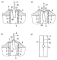
図2には、洗浄槽4内に洗浄物としてフライパン9を出し入れするときの、蓋5の弾性変形の様子が示されている。   FIG. 2 shows the state of elastic deformation of the lid 5 when the frying pan 9 is taken in and out of the washing tank 4 as a washing object.

使用者がフライパン9の柄部分91を把持して、フライパン9の鍋部分90を上方から洗浄槽4内に挿入する際、蓋5の右部位52の先端部と左部位51の先端部は、図1(b)に示す閉塞状態から図2(a)に示す開口状態へと大きく下方へ弾性変形する。このとき、センサ6によってフライパン9が洗浄槽4内に存在することを検知し、この検知結果を制御部で受けて、制御部によって洗浄水吐出装置8と紫外線照射装置7を駆動する。   When the user grasps the handle portion 91 of the frying pan 9 and inserts the pan portion 90 of the frying pan 9 into the cleaning tank 4 from above, the distal end portion of the right portion 52 and the distal end portion of the left portion 51 of the lid 5 are It is elastically deformed downward from the closed state shown in FIG. 1B to the open state shown in FIG. At this time, it is detected by the sensor 6 that the frying pan 9 is present in the cleaning tank 4, the detection result is received by the control unit, and the cleaning water discharge device 8 and the ultraviolet irradiation device 7 are driven by the control unit.

使用者が図2(a)に示す状態から更にフライパン9を下方へと挿入すると、蓋5の右部位52の先端部と左部位51の先端部は、図2(b)に示すように、フライパン9の柄部分91に接触するように弾性変形する。このとき、蓋5の右部位52の先端部と左部位51の先端部は、図2(d)に示すように、フライパン9の柄部分91に接触する前後方向の一部分のみが下方に弾性変形し、前後方向のその他の部分は、貫通孔3を閉塞する状態へと復帰することができる。これにより、蓋5は、フライパン9の柄部分91が挿通する部分以外は、貫通孔3を閉塞した状態となる。そのため、洗浄水吐出装置8から吐出される洗浄水のうち、フライパン9に当たって飛び散った水しぶきが、切れ目50から上方へと吹き出すことを抑制できる。また、紫外線照射装置7から照射された紫外線が、切れ目50から上方に漏れ出すことも抑制できる。   When the user further inserts the frying pan 9 downward from the state shown in FIG. 2A, the tip of the right part 52 and the tip of the left part 51 of the lid 5 are as shown in FIG. It is elastically deformed so as to come into contact with the handle portion 91 of the frying pan 9. At this time, as shown in FIG. 2 (d), only the part in the front-rear direction in which the front end portion of the right portion 52 and the left end portion 51 of the lid 5 are in contact with the handle portion 91 of the frying pan 9 is elastically deformed downward. And the other part of the front-back direction can return to the state which obstruct | occludes the through-hole 3. FIG. Thereby, the lid | cover 5 will be in the state which obstruct | occluded the through-hole 3 except the part into which the handle | pattern part 91 of the frying pan 9 penetrates. For this reason, it is possible to suppress the splashing of the washing water discharged from the washing water discharge device 8 from being splashed on the frying pan 9 from being blown upward from the cut 50. Moreover, it can suppress that the ultraviolet-ray irradiated from the ultraviolet irradiation device 7 leaks upwards from the cut 50. FIG.

そして、使用者がフライパン9を上方に引き出していくと、図2(c)に示すように、蓋5の右部位52の先端部と左部位51の先端部は、フライパン9の柄部分91と鍋部分90によって押し上げられて、上方に弾性変形する。このとき、少なくともフライパン9の鍋部分90の底側である左側面には、蓋5の左部位51の先端部が前後方向に亘って接触する。そのため、蓋5の左部位51の先端部とフライパン9の鍋部分90の左側面との間から上方へ水しぶきが吹き出すことや紫外線が漏れ出すことを抑制できる。   Then, when the user pulls the frying pan 9 upward, as shown in FIG. 2C, the distal end portion of the right portion 52 and the distal end portion of the left portion 51 of the lid 5 are connected to the handle portion 91 of the frying pan 9. It is pushed up by the pan portion 90 and elastically deforms upward. At this time, the tip of the left portion 51 of the lid 5 is in contact with the left and right sides at least on the bottom side of the pan portion 90 of the frying pan 9 in the front-rear direction. For this reason, it is possible to suppress the spraying of splashes and the leakage of ultraviolet rays from between the front end portion of the left portion 51 of the lid 5 and the left side surface of the pan portion 90 of the frying pan 9.

フライパン9の鍋部分90が洗浄槽4から取り出されると、蓋5の右部位52と左部位51は、図1(b)に示す閉塞状態へと復帰して、貫通孔3(開口部43)を閉塞する。このとき、センサ6によってフライパン9が洗浄槽4内に存在しないことを検知し、この検知結果を制御部で受けて、制御部によって洗浄水吐出装置8と紫外線照射装置7の駆動を停止する。   When the pan portion 90 of the frying pan 9 is taken out from the washing tub 4, the right part 52 and the left part 51 of the lid 5 return to the closed state shown in FIG. 1B, and the through hole 3 (opening 43). Occlude. At this time, it is detected by the sensor 6 that the frying pan 9 does not exist in the cleaning tank 4, the detection result is received by the control unit, and the driving of the cleaning water discharge device 8 and the ultraviolet irradiation device 7 is stopped by the control unit.

なお、制御部によって洗浄水吐出装置8及び紫外線照射装置7の駆動時間を制御することで、洗浄水吐出装置8及び紫外線照射装置7の駆動を停止した後で、使用者は図2(c)に示すように、フライパン9を上方に引き出すようにしてもよい。   Note that the control unit controls the drive time of the cleaning water discharge device 8 and the ultraviolet irradiation device 7 to stop the driving of the cleaning water discharge device 8 and the ultraviolet irradiation device 7, and then the user can use FIG. As shown, the frying pan 9 may be pulled out upward.

上述のように、フライパン9などの持ち手を有する洗浄物は、持ち手が洗浄槽4の外側で把持され、洗浄対象部位が洗浄槽4内に配置された状態で洗浄が行なわれる。そして、皿やトレイなどの持ち手を有していない洗浄物は、端の一部が洗浄槽4の外側で把持され、洗浄対象部位が洗浄槽4内に配置された状態で洗浄が行われる。   As described above, the cleaning object having a handle such as the frying pan 9 is cleaned in a state where the handle is gripped outside the cleaning tank 4 and the site to be cleaned is arranged in the cleaning tank 4. And the washing | cleaning material which does not have a handle, such as a plate and a tray, is wash | cleaned in the state in which a part of edge was hold | gripped by the outer side of the washing tank 4, and the site | part to be washed was arrange | positioned in the washing tank 4. .

以上のように、蓋5は、洗浄槽4内に挿入される洗浄物によって上方から押圧されることで、洗浄槽4の口(開口部43)をなす貫通孔3を閉塞する状態から、貫通孔3を開く状態へと弾性変形する。そのため、本実施形態の洗浄槽付き流し台では、洗浄槽4内に洗浄物を挿入するといった作業によって、洗浄槽4の口を閉塞する蓋5を開くことができる。これにより、本実施形態の洗浄槽付き流し台は、前記作業とは別に、洗浄槽4の口を閉塞する蓋5を開く作業をしなくても、洗浄槽4を利用することができ、使い勝手の良いものとなっている。   As described above, the lid 5 penetrates from the state in which the through hole 3 forming the mouth (opening 43) of the cleaning tank 4 is closed by being pressed from above by the cleaning object inserted into the cleaning tank 4. The hole 3 is elastically deformed to open. Therefore, in the sink with a cleaning tank of the present embodiment, the lid 5 that closes the mouth of the cleaning tank 4 can be opened by an operation of inserting a cleaning object into the cleaning tank 4. Thereby, the sink with a washing tank of this embodiment can utilize the washing tank 4 without performing the operation | work which opens the lid | cover 5 which obstruct | occludes the opening | mouth of the washing tank 4 separately from the said operation | work, and is convenient. It has become a good thing.

また、本実施形態の洗浄槽付き流し台では、蓋5の切れ目50の開き幅を、挿通される洗浄物の形状に合わせて変えることができる。これにより、本実施形態の洗浄槽付き流し台は、蓋5の切れ目50に挿通された洗浄物と、蓋5の切れ目50の縁部分(右部位52,左部位51)との間に隙間ができ難く、この隙間から洗浄水の吹き出しや紫外線の漏れ出しが発生し難いものとなっている。そのため、本実施形態の洗浄槽付き流し台は、様々な形状の洗浄物の洗浄に適したものとなっている。   Moreover, in the sink with a washing tank of this embodiment, the opening width of the cut 50 of the lid 5 can be changed in accordance with the shape of the washing object to be inserted. Thereby, the sink with a washing tank of this embodiment makes a clearance gap between the washing | cleaning material penetrated by the cut 50 of the lid | cover 5, and the edge part (right part 52, left part 51) of the cut 50 of the lid | cover 5. It is difficult, and it is difficult for blowout of cleaning water and leakage of ultraviolet rays to occur from this gap. Therefore, the sink with a cleaning tank of this embodiment is suitable for cleaning various shapes of cleaning objects.

また、本実施形態の洗浄槽付き流し台では、カウンター2が、上方に向けて突出する突出部分20を貫通孔3の周囲に有しているため、カウンター2上のものが洗浄槽4の口(開口部43)を閉じる蓋5上へ移動することを抑制できる。   Moreover, in the sink with a washing tank of this embodiment, since the counter 2 has the protrusion part 20 which protrudes upwards in the circumference | surroundings of the through-hole 3, the thing on the counter 2 is the opening | mouth ( It is possible to suppress the movement onto the lid 5 that closes the opening 43).

なお、上述した実施形態のようにカウンター2は、上方に向けて突出する突出部分20を貫通孔3の周囲に有することが好ましいが、図4に示す第二実施形態の洗浄槽付き流し台のように、カウンター2は、突出部分20を有していなくてもよい。なお、第二実施形態の構成のうち、既述した第一実施形態と同様の構成については、図中に同一符号を付して詳しい説明を省略する。   In addition, although it is preferable that the counter 2 has the protrusion part 20 which protrudes upward like the above-mentioned embodiment around the through-hole 3, like the sink with a washing tank of 2nd embodiment shown in FIG. In addition, the counter 2 may not have the protruding portion 20. In addition, about the structure similar to 1st embodiment mentioned already among the structures of 2nd embodiment, the same code | symbol is attached | subjected in a figure and detailed description is abbreviate | omitted.

第二実施形態の洗浄槽付き流し台では、カウンター2の貫通孔3の左右の孔縁部位は、カウンター2のその他の部位と同じ高さでフラットである。このフラットなカウンター2の貫通孔3の左右の孔縁部位に、蓋5は取り付けられている。   In the sink with washing tank of the second embodiment, the left and right hole edge portions of the through hole 3 of the counter 2 are flat at the same height as the other portions of the counter 2. Lids 5 are attached to the left and right hole edge portions of the through hole 3 of the flat counter 2.

第二実施形態の洗浄槽付き流し台においても、洗浄槽4内に洗浄物を挿入するといった作業によって、洗浄槽4の口を閉塞する蓋5を開くことができる。これにより、第二実施形態の洗浄槽付き流し台は、前記作業とは別に、洗浄槽4の口を閉塞する蓋5を開く作業をしなくても、洗浄槽4を利用することができて、使い勝手の良いものとなっている。   Also in the sink with a washing tank of the second embodiment, the lid 5 that closes the mouth of the washing tank 4 can be opened by the operation of inserting the washing object into the washing tank 4. Thereby, the sink with a washing tank of the second embodiment can use the washing tank 4 without performing the work of opening the lid 5 for closing the mouth of the washing tank 4 separately from the above work. It is easy to use.

以上、本発明を添付図面に示す実施形態に基づいて説明したが、本発明は上記の各実施形態に限定されるものではなく、本発明の意図する範囲内であれば、適宜の設計変更が可能である。   Although the present invention has been described based on the embodiments shown in the accompanying drawings, the present invention is not limited to the above-described embodiments, and appropriate design changes can be made within the intended scope of the present invention. Is possible.

1 シンク
2 カウンター
3 貫通孔
4 洗浄槽
5 蓋
7 紫外線照射装置
20 突出部分
DESCRIPTION OF SYMBOLS 1 Sink 2 Counter 3 Through-hole 4 Washing tank 5 Lid 7 Ultraviolet irradiation device 20 Protruding part

Claims (2)

シンクと、前記シンクに隣接するカウンターと、前記カウンターに形成される貫通孔と、この貫通孔に連通する洗浄槽と、前記貫通孔に装着される蓋とを、備え、
前記蓋は、前記貫通孔を閉塞し、上方から押圧されたときに弾性変形して前記貫通孔を開くものであり、
前記カウンターは、上方に向けて突出する突出部分を前記貫通孔の周囲に有することを特徴とする洗浄槽付き流し台。
A sink, a counter adjacent to the sink, a through hole formed in the counter, a cleaning tank communicating with the through hole, and a lid attached to the through hole,
The lid closes the through-hole state, and are not elastically deformed to open the through hole when pressed from above,
The counter has a protruding portion protruding upward, around the through hole .
前記洗浄槽の内側に向けて紫外線を照射する紫外線照射装置を備えることを特徴とする請求項1に記載の洗浄槽付き流し台 The sink according to claim 1, further comprising an ultraviolet irradiation device that irradiates ultraviolet rays toward the inside of the cleaning tank .
JP2013124851A 2013-06-13 2013-06-13 Sink with washing tank Active JP6172602B2 (en)

Priority Applications (1)

Application Number Priority Date Filing Date Title
JP2013124851A JP6172602B2 (en) 2013-06-13 2013-06-13 Sink with washing tank

Applications Claiming Priority (1)

Application Number Priority Date Filing Date Title
JP2013124851A JP6172602B2 (en) 2013-06-13 2013-06-13 Sink with washing tank

Publications (2)

Publication Number Publication Date
JP2015000128A JP2015000128A (en) 2015-01-05
JP6172602B2 true JP6172602B2 (en) 2017-08-02

Family

ID=52295041

Family Applications (1)

Application Number Title Priority Date Filing Date
JP2013124851A Active JP6172602B2 (en) 2013-06-13 2013-06-13 Sink with washing tank

Country Status (1)

Country Link
JP (1) JP6172602B2 (en)

Families Citing this family (1)

* Cited by examiner, † Cited by third party
Publication number Priority date Publication date Assignee Title
CN113068951B (en) * 2020-11-11 2023-09-26 深圳市商厨科技有限公司 Spliced modularized movable kitchen

Family Cites Families (5)

* Cited by examiner, † Cited by third party
Publication number Priority date Publication date Assignee Title
JPS60123152U (en) * 1984-01-25 1985-08-20 松下電工株式会社 Handled cooking utensil holder
JPH0235305Y2 (en) * 1986-09-18 1990-09-25
JPH0984733A (en) * 1995-09-27 1997-03-31 Mitsubishi Electric Corp Washing device for kitchen
JPH1046644A (en) * 1996-08-02 1998-02-17 Sekisui Chem Co Ltd Drain outlet construction of sink
JP2000093381A (en) * 1998-09-28 2000-04-04 Mitsubishi Electric Corp Dish washing and drying device

Also Published As

Publication number Publication date
JP2015000128A (en) 2015-01-05

Similar Documents

Publication Publication Date Title
KR101208889B1 (en) Dish washer
JP7190688B2 (en) ultrasonic cleaner
CA3083422A1 (en) Self-cleaning sink
JP6339712B1 (en) Cleaning method for piping including disposer
JP6172602B2 (en) Sink with washing tank
US20100212691A1 (en) Power washdown for deep fryer system
EP2108749A2 (en) Sink
JP2008274598A (en) Sink
JP4557943B2 (en) Drainage structure
KR20080012617A (en) Sink Washer
KR200402095Y1 (en) Container for washing and sterilizing spoon and chopsticks and washing and sterilizing apparatus having the same
JP6241707B2 (en) Kitchen equipment
KR20080070339A (en) Sink that can be easily cleaned by air bubbles
JP4676249B2 (en) Drain trap structure
KR20060008627A (en) Fully automatic three-dimensional ultrasonic cleaner with shower function
JP4609367B2 (en) dishwasher
CN216137773U (en) Disinfection mechanism for kitchen rag
JP2007282751A (en) Dishwasher
JP4301557B2 (en) Kitchen sink
JP3229332U (en) Garbage drainer
JP2014193253A (en) Kitchen device
JP4799233B2 (en) Endoscope washing device
JP7180194B2 (en) tank equipment
JP4797678B2 (en) Dishwasher
KR200272637Y1 (en) an ultrasouic generator

Legal Events

Date Code Title Description
A711 Notification of change in applicant

Free format text: JAPANESE INTERMEDIATE CODE: A711

Effective date: 20150312

A621 Written request for application examination

Free format text: JAPANESE INTERMEDIATE CODE: A621

Effective date: 20160421

A977 Report on retrieval

Free format text: JAPANESE INTERMEDIATE CODE: A971007

Effective date: 20170310

A131 Notification of reasons for refusal

Free format text: JAPANESE INTERMEDIATE CODE: A131

Effective date: 20170314

A521 Written amendment

Free format text: JAPANESE INTERMEDIATE CODE: A523

Effective date: 20170515

RD02 Notification of acceptance of power of attorney

Free format text: JAPANESE INTERMEDIATE CODE: A7422

Effective date: 20170515

TRDD Decision of grant or rejection written
A01 Written decision to grant a patent or to grant a registration (utility model)

Free format text: JAPANESE INTERMEDIATE CODE: A01

Effective date: 20170530

A61 First payment of annual fees (during grant procedure)

Free format text: JAPANESE INTERMEDIATE CODE: A61

Effective date: 20170623

R151 Written notification of patent or utility model registration

Ref document number: 6172602

Country of ref document: JP

Free format text: JAPANESE INTERMEDIATE CODE: R151