JP6132144B2 - Structure liquefaction damage reducing structure and liquefaction damage reducing method - Google Patents
Structure liquefaction damage reducing structure and liquefaction damage reducing method Download PDFInfo
- Publication number
- JP6132144B2 JP6132144B2 JP2013105379A JP2013105379A JP6132144B2 JP 6132144 B2 JP6132144 B2 JP 6132144B2 JP 2013105379 A JP2013105379 A JP 2013105379A JP 2013105379 A JP2013105379 A JP 2013105379A JP 6132144 B2 JP6132144 B2 JP 6132144B2
- Authority
- JP
- Japan
- Prior art keywords
- gravel layer
- foundation
- liquefaction
- outer peripheral
- ground
- Prior art date
- Legal status (The legal status is an assumption and is not a legal conclusion. Google has not performed a legal analysis and makes no representation as to the accuracy of the status listed.)
- Active
Links
Images


Landscapes
- Investigation Of Foundation Soil And Reinforcement Of Foundation Soil By Compacting Or Drainage (AREA)
- Foundations (AREA)
Description
本発明は、液状化地盤に構築される構造物を対象とする液状化被害低減構造、および液状化被害低減方法に関する。 The present invention relates to a liquefaction damage reducing structure and a liquefaction damage reducing method for a structure constructed on a liquefied ground.
従来、緩い砂層が堆積する地盤では、地震時に液状化を生じ易く、そこに構築される構造物に大きな沈下や傾斜を生じさせることがある。このような液状化を防止するためには、砂杭を造成して地盤を締め固めて密度を大きくしたり、地盤をセメント系の改良により格子状に改良することで、地震による変形を小さくする施工が行われている(例えば、特許文献1参照)。また、別の工法として、液状化しない支持層まで打ち込んだ支持杭で構造物を支持することで、液状化による沈下や傾斜を防止する方法も知られている。 Conventionally, in a ground where a loose sand layer is deposited, liquefaction is likely to occur during an earthquake, and the structure constructed there may cause large settlement or inclination. In order to prevent such liquefaction, sand piles are formed and the ground is compacted to increase the density, or the ground is improved in a grid by improving the cement system, thereby reducing the deformation caused by the earthquake. Construction has been carried out (for example, see Patent Document 1). As another construction method, there is also known a method of preventing settlement or inclination due to liquefaction by supporting a structure with a support pile driven up to a support layer that is not liquefied.
ところで、既存構造物の場合には、基礎直下の改良が困難であり、薬液注入工法など斜めボーリングで対応できる工法を採用したり、基礎に孔を空けてからロッドを地中に挿入し、高圧噴射攪拌工法で地盤を固めるなどの施工が行われている。
一方で、小規模の既存構造物の場合には、基礎の周囲に改良壁を設け、表層部を礫で置換する工法があり、基礎周囲のみを施工対象とすることで、施工費を低減することが行われている。
By the way, in the case of existing structures, it is difficult to improve directly under the foundation, and a method that can be handled by oblique boring, such as a chemical injection method, is adopted, or a hole is made in the foundation and then a rod is inserted into the ground, Construction such as solidifying the ground by the jet agitation method is being carried out.
On the other hand, in the case of small-scale existing structures, there is a construction method in which an improved wall is provided around the foundation and the surface layer is replaced with gravel. Things have been done.
しかしながら、上述した従来の液状化の被害を低減するための構造では、以下のような問題があった。
すなわち、既存の構造物基礎の直下を改良する場合には、施工費が高額となるうえ、高圧噴射攪拌工法において既存の構造物基礎に多数の孔を空ける必要があった。
また、基礎周囲に改良壁を設ける工法の場合には、基礎外周に施工機械を用いて施工できるだけの十分な作業スペースが確保できる場合に限定されるという問題があった。
さらに、地中に既設配管がある場合も多く、その箇所では高圧噴射攪拌工法などの配管に影響を与えない工法を行う必要があり、施工費が増大することから、その点で改善の余地があった。
However, the conventional structure for reducing the damage of liquefaction described above has the following problems.
That is, in the case of improving directly under the existing structure foundation, the construction cost becomes high, and it is necessary to open a large number of holes in the existing structure foundation in the high-pressure jet stirring method.
Moreover, in the case of a construction method in which an improved wall is provided around the foundation, there is a problem that it is limited to a case where a sufficient working space can be secured on the outer circumference of the foundation using a construction machine.
In addition, there are many existing pipes in the ground, and it is necessary to carry out construction methods that do not affect the pipes such as the high-pressure jet agitation method, and the construction costs increase, so there is room for improvement in that respect. there were.
本発明は、上述する問題点に鑑みてなされたもので、簡単な施工法とすることで施工費の低減を図ることができるうえ、狭い施工スペースでの施工が可能となる構造物の液状化被害低減構造、および液状化被害低減方法を提供することを目的とする。 The present invention has been made in view of the above-mentioned problems, and it is possible to reduce the construction cost by adopting a simple construction method and to liquefy the structure that enables construction in a narrow construction space. An object is to provide a damage reduction structure and a liquefaction damage reduction method.
上記目的を達成するため、本発明に係る構造物の液状化被害低減構造では、液状化地盤に構築される構造物を対象とし、液状化地盤が液状化した際に構造物の被害を低減させるための構造であって、平面視で構造物の構造物基礎の外周側のみに礫を敷設することにより形成され液状化地盤よりも透水係数が大きい排水機能を有する礫層部を設け、礫層部に構造物基礎の外周部分が接続されていることを特徴としている。 In order to achieve the above object, the structure for reducing liquefaction damage of a structure according to the present invention targets a structure constructed on a liquefied ground, and reduces damage to the structure when the liquefied ground is liquefied. A gravel layer portion having a drainage function that is formed by laying gravel only on the outer peripheral side of the structure foundation of the structure in plan view and having a drainage function larger than the liquefied ground. The outer peripheral part of the structure foundation is connected to the part.
また、本発明に係る構造物の液状化被害低減方法では、液状化地盤に構築される構造物を対象とし、液状化地盤が液状化した際に構造物の被害を低減させるための液状化被害低減方法であって、平面視で構造物の構造物基礎の外周側のみを掘削して礫を敷設することにより、液状化地盤よりも透水係数が大きい排水機能を有する礫層部を設ける工程と、礫層部に構造物基礎の外周部分を接続させる工程と、を有することを特徴としている。 Further, in the structure liquefaction damage reducing method according to the present invention, liquefaction damage for reducing the damage to the structure when the liquefied ground is liquefied is intended for the structure constructed on the liquefied ground. A method of reducing a gravel layer having a drainage function having a larger hydraulic conductivity than the liquefied ground by excavating only the outer peripheral side of the structure foundation of the structure in plan view and laying the gravel; And a step of connecting the outer peripheral portion of the structure foundation to the gravel layer portion.
本発明では、構造物基礎の外周側のみに礫層部を設け、その礫層部に構造物基礎の外周部分を接続させるという表層部分での作業のみとする簡単な施工により、少なくとも構造物基礎の周囲においては礫層部直下の原地盤である液状化地盤に液状化が生じた場合に砂の流動や噴砂が生じることを有効に防止することができる。
つまり、礫層部が排水層の機能を有し、地震により液状化地盤内に生じた過剰間隙水を礫層部により集水するとともに、さらにその水が礫層部内を通じて地上に排水される。そして、液状化地盤内において、液状化に伴って生じる過剰間隙水圧を抑制することができ、砂の流動や噴砂を抑えることができる。これにより、構造物に傾斜や沈下が生じることや周辺地盤との間に大きな不陸が生じることを抑制し得て液状化被害を有効に低減させることが可能である。このように、地震時の液状化層において過剰間隙水圧比が1に達した後にせん断変形により剛性が回復する状態(これを「ポスト液状化状態」という)を保持して安定した変形挙動をするように制御することが可能となる。そのため、構造物基礎の周りの液状化を早期に収束させて地盤を安定させることで、構造物直下の地盤に液状化が生じても、その上の構造物に生じる傾斜を軽減することが可能である。
In the present invention, at least the structure foundation is obtained by a simple construction in which the gravel layer portion is provided only on the outer peripheral side of the structure foundation and the outer peripheral portion of the structure foundation is connected to the gravel layer portion. In the surroundings, when liquefaction occurs in the liquefied ground, which is the original ground immediately below the gravel layer, it is possible to effectively prevent the flow of sand and the occurrence of sand sand.
That is, the gravel layer portion functions as a drainage layer, and excess pore water generated in the liquefied ground due to the earthquake is collected by the gravel layer portion, and further, the water is drained to the ground through the gravel layer portion. And in the liquefied ground, the excessive pore water pressure which arises with liquefaction can be suppressed, and the flow of sand and sand sand can be suppressed. As a result, it is possible to suppress liquefaction damage by effectively suppressing the occurrence of inclination or subsidence in the structure and the occurrence of large unevenness with the surrounding ground. In this way, in the liquefied layer at the time of the earthquake, after the excess pore water pressure ratio reaches 1, the state where the rigidity is restored by shear deformation (this is called “post-liquefaction state”) is maintained and a stable deformation behavior is achieved. It becomes possible to control. Therefore, by stabilizing the liquefaction around the structure foundation at an early stage, even if liquefaction occurs in the ground directly under the structure, it is possible to reduce the slope generated in the structure above it. It is.
また、本発明では、構造物の直下の地盤に対する作業を少なくすることができ、また礫層部が表層付近のみの施工となり、礫層部を液状化地盤の深部に至るように形成する必要もなく、単に礫層部を設ける領域の掘削と、その掘削箇所に礫材を充填して敷設する作業となる。そのため、小型の機械や人力によって施工が可能であり、従来の地盤改良工法のように大型の施工機械を設置する必要がなく、狭隘地であっても対応することができる。したがって、戸建て住宅等の小規模構造物に適用するものとして好適であるし、特に直下に対する作業が困難である既存構造物に対する液状化対策として最適である。 Further, in the present invention, the work on the ground directly under the structure can be reduced, and the gravel layer is constructed only in the vicinity of the surface layer, and the gravel layer needs to be formed so as to reach the deep part of the liquefied ground. Rather, the excavation of the region where the gravel layer portion is provided and the operation of filling the excavation site with gravel material and laying it. Therefore, construction can be performed by a small machine or manpower, and it is not necessary to install a large construction machine as in the conventional ground improvement method, and it is possible to cope even in a narrow area. Therefore, it is suitable for application to a small-scale structure such as a detached house, and is particularly suitable as a liquefaction countermeasure for an existing structure that is difficult to work directly below.
さらに、本発明が礫材を敷設することによる施工方法となることから、地盤中に既設の配管がある場合であっても、従来のような高圧噴射攪拌工法等のコストのかかる工法を採用せずに、既設配管に影響を与えることなく施工が可能となる利点を有している。
さらにまた、本発明は、液状化を防止する工法ではなく、構造物が周辺地盤とともに沈下するため、周辺地盤との間に生じる段差が小さくなる。そのため、地盤中に既設の配管があっても、液状化を完全に防止した場合に比べて地中の既設配管への影響を小さく抑えることができる。
Furthermore, since the present invention is a construction method by laying gravel material, even if there is an existing pipe in the ground, a costly construction method such as a conventional high-pressure jet stirring method is adopted. In addition, there is an advantage that the construction can be performed without affecting the existing piping.
Furthermore, the present invention is not a method for preventing liquefaction, and the structure sinks with the surrounding ground, so that the level difference between the surrounding ground and the ground is reduced. Therefore, even if there is an existing pipe in the ground, the influence on the existing pipe in the ground can be suppressed smaller than in the case where liquefaction is completely prevented.
また、本発明に係る構造物の液状化被害低減構造では、構造物基礎の外周部分は、構造物基礎の外周部に対して一体的に設けられる拡幅部であってもよい。 In the structure liquefaction damage reducing structure according to the present invention, the outer peripheral portion of the structure foundation may be a widened portion provided integrally with the outer peripheral portion of the structure foundation.
また、本発明に係る構造物の液状化被害低減方法では、構造物基礎の外周部に拡幅部を一体的に設け、拡幅部を礫層部に接続するようにしてもよい。 In the structure liquefaction damage reducing method according to the present invention, a widened portion may be integrally provided on the outer periphery of the structure foundation, and the widened portion may be connected to the gravel layer portion.
この場合には、既存の構造物基礎に対して拡幅部を後施工により設けることができ、その拡幅部を礫層部に接続する構造となる。そのため、既存の構造物基礎の直下に礫層部を設けるといった困難な施工が不要となることから、施工費の増大を抑えることができる。 In this case, the widened portion can be provided by post-construction with respect to the existing structure foundation, and the widened portion is connected to the gravel layer portion. Therefore, since difficult construction such as providing a gravel layer portion directly under an existing structure foundation is not required, an increase in construction costs can be suppressed.
また、本発明に係る構造物の液状化被害低減構造では、拡幅部には、水平方向で構造物基礎から離れる方向の拡幅距離を部分的に大きくした突状部が形成される構成としてもよい。 Further, in the structure liquefaction damage reducing structure according to the present invention, the widened portion may be formed with a protruding portion in which the widened distance in the direction away from the structure foundation in the horizontal direction is partially increased. .
この場合には、突状部と礫層部とを嵌合状態で形成することができるので、平面視で突状部が拡大する方向(構造物基礎から離れる方向)に対して直交する方向側への構造物の傾斜を抑制する効果を高めることができる。そのため、例えば既存構造物に近接して他の構造物が設けられ、その他の構造物側に礫層部を設けることが困難な場合には、その他の構造物側でない側の拡幅部に突状部を形成することで、他の構造物側への構造物の傾斜を抑えることができる。 In this case, since the projecting portion and the gravel layer portion can be formed in a fitted state, the direction side orthogonal to the direction in which the projecting portion expands (the direction away from the structure foundation) in plan view. The effect which suppresses the inclination of the structure to a can be heightened. Therefore, for example, when another structure is provided in the vicinity of an existing structure and it is difficult to provide a gravel layer on the other structure side, it protrudes into the widened part on the side other than the structure side. By forming the portion, the inclination of the structure toward the other structure side can be suppressed.
また、本発明に係る構造物の液状化被害低減構造では、拡幅部は、平面視で構造物基礎に沿って部分的に配置される構成とすることも可能である。 Moreover, in the structure liquefaction damage reducing structure according to the present invention, the widened portion may be partially arranged along the structure foundation in a plan view.
この場合には、拡幅部の施工面積を小さくすることが可能となるので、施工費を低減することができる。 In this case, since the construction area of the widened portion can be reduced, the construction cost can be reduced.
また、本発明に係る構造物の液状化被害低減構造では、構造物基礎の外周部分は、構造物基礎の外周部から外方に向けて突出し、且つ構造物基礎に一体的に固定された張出し部とすることもできる。 In the structure liquefaction damage reducing structure according to the present invention, the outer peripheral portion of the structure foundation protrudes outward from the outer periphery of the structure foundation and is integrally fixed to the structure foundation. It can also be a part.
また、本発明に係る構造物の液状化被害低減方法では、構造物基礎の外周部から外方に向けて突出する張出し部を設け、張出し部を礫層部に接続するようにしてもよい。 Further, in the structure liquefaction damage reducing method according to the present invention, an overhanging portion protruding outward from the outer peripheral portion of the structure foundation may be provided, and the overhanging portion may be connected to the gravel layer portion.
この場合には、既存の構造物基礎に対して張出し部を後施工により設けることができ、その張出し部を礫層部の接続する構造となる。そのため、既存の構造物基礎の直下に礫層部を設けるといった困難な施工が不要となることから、施工費の増大を抑えることができる。しかも、構造物基礎を拡大する場合に比べて、地表面に沿う部分にのみ張出し部を設ければよい構成となり、施工にかかる手間や時間を低減することができる。 In this case, the overhanging portion can be provided by post-construction with respect to the existing structure foundation, and the overhanging portion is connected to the gravel layer portion. Therefore, since difficult construction such as providing a gravel layer portion directly under an existing structure foundation is not required, an increase in construction costs can be suppressed. And compared with the case where a structure foundation is expanded, it becomes the structure which should just provide an overhang | projection part only in the part along a ground surface, and the effort and time concerning construction can be reduced.
また、本発明に係る構造物の液状化被害低減構造では、張出し部は、平面視で構造物基礎に沿って部分的に配置されている構成としてもよい。 Moreover, in the structure liquefaction damage reducing structure according to the present invention, the overhanging portion may be partially arranged along the structure foundation in a plan view.
この場合には、張出し部の施工面積を小さくすることが可能となるので、施工費を低減することができる。 In this case, since the construction area of the overhang portion can be reduced, the construction cost can be reduced.
また、本発明に係る構造物の液状化被害低減構造では、礫層部に連通するとともに、礫層部から鉛直方向で下方に延びる透水性を有する鉛直ドレーンが設けられている構成とすることができる。 Further, in the structure for reducing liquefaction damage of a structure according to the present invention, a vertical drain having water permeability that extends downward in the vertical direction from the gravel layer portion is provided while communicating with the gravel layer portion. it can.
この場合には、地震により液状化地盤内に生じた過剰間隙水を鉛直ドレーンにより集水し、さらにその水が鉛直ドレーンから礫層部にくみ上げられ、礫層部内を通じて地上に排水される。そのため、例えば構造物基礎の底面位置の深さよりもさらに深い位置の掘削が難しい場合にも、所定の深さまで礫層部と同様の排水機能を鉛直ドレーンにもたせることができる。
また、鉛直ドレーンを打設する場合にも、既設の配管を避けて施工することが可能であり、その既設配管に影響を与えるのを防止することができる。
In this case, excess pore water generated in the liquefied ground due to the earthquake is collected by the vertical drain, and the water is pumped from the vertical drain to the gravel layer and drained to the ground through the gravel layer. Therefore, for example, even when excavation at a deeper position than the depth of the bottom surface position of the structure foundation is difficult, the drainage function similar to that of the gravel layer portion can be provided to the vertical drain to a predetermined depth.
In addition, when a vertical drain is placed, it is possible to perform construction while avoiding the existing piping, and it is possible to prevent the existing piping from being affected.
本発明の構造物の液状化被害低減構造、および液状化被害低減方法によれば、構造物基礎を表層部分に設けた礫層部に接続するといった簡単な施工法とすることで、施工費の低減を図ることができるうえ、狭い施工スペースでの施工が可能となる効果を奏する。 According to the structure for reducing liquefaction damage and the method for reducing liquefaction damage of the present invention, the construction cost can be reduced by connecting the structure foundation to the gravel layer provided on the surface layer. In addition to being able to achieve reduction, the effect is that construction in a narrow construction space is possible.
以下、本発明の実施の形態による構造物の液状化被害低減構造、および液状化被害低減方法について、図面に基づいて説明する。 Hereinafter, a structure liquefaction damage reducing structure and a liquefaction damage reducing method according to embodiments of the present invention will be described with reference to the drawings.
(第1の実施の形態)
図1および図2に示すように、本第1の実施の形態による構造物の液状化被害低減構造1は、原地盤が液状化地盤Gである敷地に構築される既存の構造物2(例えば、戸建の住宅等)を対象として、その直下の原地盤に対する作業を必要とせずに液状化被害を低減する場合に適用される一例である。構造物2には平面形状で構造物2よりも一回り大きな構造物基礎21が液状化地盤G中に設けられ、構造物2および構造物基礎21はそれぞれ平面視で矩形状をなしている。
(First embodiment)
As shown in FIGS. 1 and 2, the structure liquefaction
具体的に液状化被害低減構造1は、構造物基礎21の外周側に全周にわたって礫を敷設することにより形成され液状化地盤Gよりも透水係数が大きい排水機能を有する礫層部3を設け、この礫層部3に構造物基礎21の外周部分(後述する拡幅部22)が載置するようにして接続されて構成されている。構造物基礎21の外周部21aには、構造物基礎2から外方に向けて延設された拡幅部22が一体的に設けられている。
Specifically, the liquefaction
礫層部3は、構造物2の周囲を所定深さで掘削した箇所に、例えば天然の礫材(砂利)を敷き詰めて埋め戻すことにより造成される。このとき、地表面まで敷き詰めず、拡幅部22を設ける領域をあけた状態で形成しておく。礫層部3の深度は、例えば基礎下から30cm〜1m程度とされる。なお、礫材として、同等の透水性能が得られるものであれば砕石や各種の人工透水性材料も採用可能である。また、礫層部3は、礫が詰った土嚢を敷き詰めるようにしてもよい。
The
この礫層部3は、表層部分に設けられ、構造物2の下方の液状化地盤Gにおいて液状化が生じた際に過剰間隙水を地表に効率的に排水して地表への噴砂が生じることを防止するためのものである。そのため、この礫層部3の透水係数は原地盤である液状化地盤Gよりも大きくする必要があり、例えば液状化地盤Gよりも2桁(100倍)程度以上大きくすることが好ましい。
This
なお、礫層部3は地震時に破断することなく変形し得るような柔軟性を有するように非固結状態で形成することが好ましい。つまり、礫層部3を固結状態で硬直な状態で形成した場合には地震時に礫層部3が破断してしまってそこに隙間が生じたり、あるいは礫層部3全体が構造物2に対して相対変位を生じてそれらの間に隙間が生じる余地があり、その場合には隙間から噴砂が生じてしまう。これに対し、礫層部3を非固結状態で形成して地震時における変形を吸収可能な程度の柔軟性を有するものとすることにより、礫層部3が破断したり隙間が生じることを防止でき、その隙間から噴砂が生じることを有効に防止することが可能である。
In addition, it is preferable to form the
また、礫層部3は、目詰まりを防止するために、例えば下から5cm程度上までの範囲には礫径の小さな礫を敷き詰めるようにしてもよい。なお、礫径は、ディープウェルのフィルター材の設計などに基づいて適宜な寸法に設定することができる。
さらに、礫層部3と原地盤(液状化地盤G)との間にフィルターとなるジオテキスタイルを介在させることで、礫層部3の目詰まりを防ぐとともに、透水性を維持するようにしてもよい。
Moreover, in order to prevent clogging, the
Further, by interposing a geotextile serving as a filter between the
図1に示すように、構造物基礎21を拡大させた拡幅部22は、鉄筋コンクリート造で形成され、既存の構造物基礎21の側面(外周部21a)に対してアンカーボルト等の連結材23を介して一体的に設けられている。この拡幅部22は、敷設される礫層部3の幅方向Xの内側に位置するように配置されている。そして、拡幅部22が礫層部3の地表面側の部分にかかるように配置され、拡幅部22の側面22a及び底面22bが礫層部3に対して隙間なく接触した状態となっている。すなわち、拡幅部22の側面22a側に位置する上部礫層部3Aは、その下方の下部礫層部3Bに対して上下方向に連通している。
なお、拡幅部22は、礫層部3の施工後に構造物基礎21の外周部21aに施工してもよいし、先に構造物基礎21に一体的に設けた後に礫層部3を施工する工程としてもよい。
As shown in FIG. 1, the widened
In addition, the widening
次に、上述した構成の液状化被害低減構造1の作用について、図面に基づいて詳細に説明する。
図1および2に示すように、液状化被害低減構造1は、構造物基礎21の外周側に礫層部3を設け、その礫層部3に構造物基礎21の拡幅部22を接続させるという表層部分のみとする簡単な施工により、少なくとも構造物基礎21の周囲においては礫層部3の直下の原地盤である液状化地盤Gに液状化が生じた場合に、砂の流動や噴砂が生じることを有効に防止することができる。
つまり、礫層部3が排水層の機能を有し、地震により液状化地盤G内に生じた過剰間隙水を礫層部3により集水するとともに、さらにその水が礫層部3内を通じて地上に排水される。そして、液状化地盤G内において、液状化に伴って生じる過剰間隙水圧を抑制することができ、砂の流動や噴砂を抑えることができる。これにより、構造物2に傾斜や沈下が生じることや周辺地盤との間に大きな不陸が生じることを抑制し得て液状化被害を有効に低減させることが可能である。
Next, the operation of the liquefaction
As shown in FIGS. 1 and 2, the liquefaction
That is, the
このように、地震時の液状化地盤Gにおいて過剰間隙水圧比が1に達した後にせん断変形により剛性が回復する状態(これを「ポスト液状化状態」という)を保持して安定した変形挙動をするように制御することが可能となる。そのため、構造物基礎21の周りの液状化を早期に収束させて地盤を安定させることで、構造物2の直下の地盤に液状化が生じても、その上の構造物2に生じる傾斜を軽減することが可能である。
Thus, in the liquefied ground G at the time of the earthquake, after the excess pore water pressure ratio reaches 1, the state where the rigidity is restored by shear deformation (this is referred to as “post-liquefaction state”) and stable deformation behavior is maintained. It becomes possible to control to do. Therefore, by stabilizing the liquefaction around the
ここで、通常の液状化に対する設計手法では、地盤の過剰間隙水圧比が1に達した状態を完全に液状化した状態(液体になった状態)として、これ以降の状態を考えることはないが、ポスト液状化状態を呈することに着目し、そのポスト液状化状態を安定に継続させることで構造物2に対する支持力を維持し確保するという設計思想に基づいている。
すなわち、図3に示すように、ポスト液状化状態に達した地盤に対して排水することなくさらにせん断力を作用し続けると、非可逆の塑性体積ひずみ(圧縮側)にダイレクタンシーによる可逆的な塑性体積ひずみ(膨張側)が追いつけず、地盤が完全な液体状態なる。この状態が噴砂や構造物の不同沈下が生じる地盤の破壊に達した状態である。
一方、適切に排水しながら上記のせん断力を作用させると、非可逆の塑性体積ひずみ圧縮側)と可逆的な塑性体積ひずみ(膨張側)が常に釣り合い、ポスト液状化状態が安定に継続するから、本実施の形態はそのような安定なポスト液状化状態を保持することで構造物の支持力を確保するという技術思想に基づき、構造物の沈下や傾斜といった液状化被害を低減するものである。
なお、本実施の形態の有効性については、本出願人が先に特願2012−18495により記載した解析実験に基づいて確認することができる。
Here, in the design method for normal liquefaction, the state where the excess pore water pressure ratio of the ground has reached 1 is not considered as the state after this as a completely liquefied state (a state in which it has become liquid). Focusing on exhibiting the post-liquefaction state, the design philosophy is to maintain and secure the supporting force for the
That is, as shown in FIG. 3, if a shear force continues to act on the ground that has reached the post-liquefaction state without draining, the reversible due to the directivity is applied to the irreversible plastic volume strain (compression side). Plastic volume strain (expansion side) cannot catch up, and the ground becomes completely liquid. This state is the state that reached the destruction of the ground where the undesired subsidence of the sand and structures.
On the other hand, if the above shear force is applied while draining properly, the irreversible plastic volume strain compression side) and the reversible plastic volume strain (expansion side) are always balanced, and the post-liquefaction state continues stably. The present embodiment reduces the liquefaction damage such as subsidence and inclination of the structure based on the technical idea of ensuring the supporting force of the structure by maintaining such a stable post-liquefaction state. .
In addition, about the effectiveness of this Embodiment, this applicant can confirm based on the analysis experiment previously described by Japanese Patent Application No. 2012-18495.
また、図1および図2に示すように、本実施の形態の液状化被害低減構造1では、構造物2の直下の地盤に対する作業を少なくすることができ、また礫層部3が表層付近のみの施工となり、礫層部3を液状化地盤Gの深部に至るように形成する必要もなく、単に礫層部3を設ける領域の掘削と、その掘削箇所に礫材を充填して敷設する作業となる。そのため、小型の機械や人力によって施工が可能であり、従来の地盤改良工法のように大型の施工機械を設置する必要がなく、狭隘地であっても対応することができる。したがって、戸建て住宅等の小規模構造物に適用するものとして好適であるし、特に直下に対する作業が困難である既存構造物に対する液状化対策として最適である。
Further, as shown in FIGS. 1 and 2, in the liquefaction
さらに、礫材を敷設することによる施工方法となることから、地盤中に既設の配管がある場合であっても、従来のような高圧噴射攪拌工法等のコストのかかる工法を採用せずに、既設配管に影響を与えることなく施工が可能となる利点を有している。
さらにまた、本実施の形態の液状化被害低減構造1は、液状化を防止する工法ではなく、構造物2が周辺地盤とともに沈下するため、周辺地盤との間に生じる段差が小さくなる。そのため、地盤中に既設の配管があっても、液状化を完全に防止した場合に比べて地中の既設配管への影響を小さく抑えることができる。
Furthermore, since it becomes a construction method by laying gravel material, even if there are existing pipes in the ground, without adopting costly construction methods such as the conventional high-pressure jet stirring method, It has the advantage that it can be constructed without affecting the existing piping.
Furthermore, the liquefaction
また、既存の構造物基礎21に対して拡幅部22を後施工により設けることができ、その拡幅部22を礫層部3に接続する構造となる。そのため、既存の構造物基礎21の直下に礫層部3を設けるといった困難な施工が不要となることから、施工費の増大を抑えることができる。
Moreover, the widening
上述のように本第1の実施の形態による構造物の液状化被害低減構造、および液状化被害低減方法では、構造物基礎21を表層部分に設けた礫層部3に接続するといった簡単な施工法とすることで、施工費の低減を図ることができるうえ、狭い施工スペースでの施工が可能となる効果を奏する。
As described above, in the structure liquefaction damage reducing structure and the liquefaction damage reducing method according to the first embodiment, a simple construction in which the
次に、本発明の構造物の液状化被害低減構造、および液状化被害低減方法による他の実施の形態について、添付図面に基づいて説明するが、上述の第1の実施の形態と同一又は同様な部材、部分には同一の符号を用いて説明を省略し、第1の実施の形態と異なる構成について説明する。 Next, another embodiment of the structure liquefaction damage reducing structure and liquefaction damage reducing method of the present invention will be described with reference to the accompanying drawings, but the same as or similar to the first embodiment described above. Components and parts that are the same as those in the first embodiment will be described using the same reference numerals and description thereof will be omitted.
(第2の実施の形態)
図4に示すように、第2の実施の形態による液状化被害低減構造1Aは、構造物基礎21の外周全てにわたって拡幅部22を設ける必要はなく、平面視で矩形状の既存の構造物2に対して対向する2方向のみに拡幅部22と礫層部3が設けられた構成となっている。すなわち、構造物基礎21における礫層部3を設けない他の対向する2方向には、近接構造物4が建築されている。
また、図5に示す液状化被害低減構造1Bは、平面視で矩形状の既存の構造物2に対して3方向に拡幅部22と礫層部3が設けられた構成となっている。この場合も、構造物基礎21における礫層部3を設けない他の1方向には、近接構造物4が建築されている。
(Second Embodiment)
As shown in FIG. 4, the liquefaction
Further, the liquefaction
このように、液状化被害低減構造は、構造物2の外周全体にわたって礫層部3を設ける必要はない。そのため、液状化被害を低減する構造物2の周囲の一部に近接構造物4が設けられている場合であっても、本実施の形態の液状化被害低減構造を適用することが可能である。
Thus, the liquefaction damage reducing structure does not require the
(第3の実施の形態)
次に、図6に示すように、第3の実施の形態による液状化被害低減構造1Cでは、上述した第2の実施の形態による2方向に礫層部3を設ける液状化被害低減構造1A(図4参照)の拡幅部22において、水平方向で構造物基礎21から離れる方向(矢印E方向)の拡幅距離を部分的に大きくした突状部24を形成させた構成となっている。
この場合には、突状部24と礫層部3とが嵌合した状態で設けられるので、平面視で突状部24が拡大する方向Eに直交する方向F側への構造物2の傾斜を抑制する効果を高めることができる。そのため、本実施の形態のように、既存の構造物2に近接して他の構造物(近接構造物4)が設けられ、その近接構造物4側に礫層部3を設けることが困難な場合には、その近接構造物4側でない側の拡幅部22に突状部24を形成することで、近接構造物4側への構造物2の傾斜を抑えることができる。
(Third embodiment)
Next, as shown in FIG. 6, in the liquefaction
In this case, since the
(第4の実施の形態)
次に、図7に示すように、第4の実施の形態による液状化被害低減構造1Dでは、ブロック状の複数の拡幅部22Aが平面視で構造物基礎21の外周部21aに沿って間隔をあけて部分的に配置され、拡幅部22Aを囲う部分のみに礫層部3を設けた構成となっている。
この場合には、拡幅部22Aの施工面積を小さくすることが可能となるので、施工費を低減することができる。
(Fourth embodiment)
Next, as shown in FIG. 7, in the liquefaction
In this case, the construction area of the widened
(第5の実施の形態)
また、図8および図9に示すように、第5の実施の形態による液状化被害低減構造1Eでは、礫層部3に連通するとともに、液状化地盤G内で礫層部3から鉛直方向で下方に延びる透水性を有する複数の鉛直ドレーン5が構造物基礎21の外周部21aに沿う方向に所定間隔をあけて設けられた構成となっている。ここで、本実施の形態の礫層部3の深度は、構造物基礎21よりも浅い位置となっている。鉛直ドレーン5は、礫層部3と同様の砂利や砂礫などの透水性を有する材料が用いられるが、鉛直ドレーン5よりもさらに透水性の高い材料によって構成されていてもよい。
(Fifth embodiment)
As shown in FIGS. 8 and 9, in the liquefaction
本第5の実施の形態では、地震により液状化地盤G内に生じた過剰間隙水を複数の鉛直ドレーン5により集水し、さらにその水が鉛直ドレーン5から礫層部3にくみ上げられ、礫層部3内を通じて地上に排水することが可能になる。そのため、本実施の形態のように、構造物基礎21の底面位置の深さよりもさらに深い位置の掘削が難しい場合にも、所定の深さまで礫層部3と同様の排水機能を鉛直ドレーン5にもたせることができる。
また、鉛直ドレーン5を打設する場合にも、既設の配管を避けて施工することが可能であり、その既設配管に影響を与えるのを防止することができる。
In the fifth embodiment, excess pore water generated in the liquefied ground G due to the earthquake is collected by a plurality of
In addition, when the
(第6の実施の形態)
次に、図10に示すように、第6の実施の形態による液状化被害低減構造1Fは、上述した拡幅部22に代えて、構造物基礎21の外周部21aから外方に向けて突出し、且つ構造物基礎21に対して一体的に固定された板状の張出し部25を設けた構成としたものである。張出し部25は、構造物2の外周全周にわたって配置され、構造物2側の部分25aが構造物基礎21の上縁部に対して例えばアンカーボルトなどの固定治具26によって固定され、面方向をほぼ地表面に沿うように、且つ礫層部3の上端の内側部分を覆うようにして配置され、礫層部3に接続されている。ここで、張出し部25は、必ずしも構造物基礎21と同じ厚さ寸法、剛性とすることに限定されることはない。また、張出し部25は、本実施の形態では板状としているが、板状であることに制限されることはなく、例えばL形鋼やチャンネル材などの鋼材を構造物基礎21の外周部21aから外方に向けて突出させるものとすることも可能である。
(Sixth embodiment)
Next, as shown in FIG. 10, the liquefaction
この場合には、既存の構造物基礎21に対して張出し部25を後施工により設けることができ、その張出し部25を礫層部3に接続する構造となる。そのため、既存の構造物基礎21の直下に礫層部3を設けるといった困難な施工が不要となることから、施工費の増大を抑えることができる。しかも、構造物基礎21を拡大する場合に比べて、地表面に沿う部分にのみ張出し部25を設ければよい構成となり、施工にかかる手間や時間を低減することができる。
なお、前記張出し部25は、平面視で構造物基礎21に沿って部分的に配置されていてもよい。この場合には、張出し部25の施工面積を小さくすることが可能となるので、施工費を低減することができる。
In this case, the overhanging
In addition, the said overhang |
(第7の実施の形態)
また、図11に示すように、第7の実施の形態による液状化被害低減構造1Gは、構造物基礎21に上述したような拡幅部22や張出し部25を設けずに、構造物基礎21の外周部分の下を掘削し、礫層部3を敷設するようにした構成となっている。この場合、構造物基礎21がある程度大きく、剛性も十分な場合に適用することができる。
(Seventh embodiment)
Moreover, as shown in FIG. 11, the liquefaction
次に、上述した実施の形態による構造物の液状化被害低減構造、および液状化被害低減方法の効果を裏付けるための実施例について、以下説明する。 Next, examples for supporting the effects of the structure liquefaction damage reducing structure and the liquefaction damage reducing method according to the above-described embodiment will be described below.
(第1実施例)
第1実施例は、上述した第1の実施の形態と同様の液状化被害低減構造の模型と無対策の模型を使用して実験を行い、その効果を確認したものである。
図12(a)及び(b)は、図1に示す液状化被害低減構造1Aと同様の構成をなす実験モデル図(実験模型100)である。すなわち、実験模型100は、構造物基礎に相当する構造物101の外周側に全周にわたって礫を敷設することにより形成され液状化層102よりも透水係数が大きい排水機能を有する礫層部103を設け、この礫層部103に構造物101の外周部分(拡幅部104)が載置するようにして接続されて構成されている。構造物101の外周部には、構造物101から外方に向けて延設された拡幅部104が一体的に設けられている。
(First embodiment)
In the first example, an experiment was conducted using a model of a liquefaction damage reducing structure similar to the first embodiment described above and a model without countermeasures, and the effect was confirmed.
FIGS. 12A and 12B are experimental model diagrams (experimental model 100) having the same configuration as the liquefaction damage reducing structure 1A shown in FIG. That is, the
図12(b)に示す実験模型100は、土槽内寸法で800mm×470mm×370mmのせん断土層を用いている。地盤は、土槽底部に非液状化層105である相対密度90%以上の3号珪砂層を厚さ50mm設け、その上に液状化層102として7号珪砂にカオリン粘土を乾燥重量比95:5で混合したものを空中落下法により相対密度35%、厚さ240mmで作成した。間隙流体は、30csのシリコンオイルを用い、地下水位は地表面とした。
構造物101は、平面が80mm角で荷重が偏心しているベース厚さが12mmのアルミ製の構造物とし、平均接地圧を34kN/m2としている。拡幅部104は、長さ80mm、幅17mm、厚さ10mmのアルミ材をボルトにより構造物101のベースに固定している。
排水層となる礫層部103は、3号珪砂を使用し、幅33mmで、相対密度が90%以上となるように作成した。
The
The
The
実験は、遠心加速度30g下で行うものとし、構造物101の偏心荷重が大きいため、遠心載荷時に構造物101が傾斜しないようにカウンターウエイトにより偏心がない状態で遠心載荷を行う、一旦、遠心加速度を除荷してカウンターウエイトを外し、再度遠心載荷を行って加振実験を実施した。そして、加振開始時には、構造物101の直下の地盤は、過圧密状態にある。入力波は、実換算で最大加速度300cm/s2の2Hz正弦波を用い、漸増100波、定常60波、漸減5波で加振時間は82.5秒とした。
The experiment is performed under a centrifugal acceleration of 30 g, and since the eccentric load of the
図13は、横軸に地震後経過時間(分)、縦軸に基礎傾斜増分(rad)とした本第1実施例の実験結果を示しており、液状化被害低減構造による基礎全方向の実験模型100(第1対策T1)と無対策T0との場合において、地震後の傾斜増分(rad)を比較したものである。これによると、無対策の場合には、地震後に徐々に傾斜が増加し、最終的には30°もの残留傾斜が生じている。一方、第1対策T1の場合(すなわち、液状化被害低減対策を施した場合)には、傾斜の増加がほとんど無い結果となっている。 FIG. 13 shows the experimental results of the first example in which the horizontal axis indicates the elapsed time after the earthquake (minutes) and the vertical axis indicates the basic slope increment (rad). In the case of the model 100 (first countermeasure T1) and the non-measure T0, the slope increment (rad) after the earthquake is compared. According to this, in the case of no countermeasures, the slope gradually increases after the earthquake and finally a residual slope of 30 ° is generated. On the other hand, in the case of the first countermeasure T1 (that is, when liquefaction damage reduction countermeasures are taken), there is almost no increase in inclination.
(第2実施例)
第2実施例は、上述した第2の実施の形態と同様の液状化被害低減構造の模型を使用して実験を行い、その効果を確認したものである。すなわち、図12に示す上記第1実施例の実験模型100は構造物101の外周側に全周にわたって拡幅部104と礫層部103を設けているが、本第2実施例では構造物101に対して対向する2方向のみに拡幅部104と礫層部103を設けた実験模型(2方向対策)を使用し、第1実施例と同様の条件で実験を行い、その効果を確認した。ここで、2方向対策に設けられる液状化被害低減構造として、荷重偏心方向2方向のみに対策したもの(第2対策T2)と、荷重偏心方向に直交する方向の2方向のみに対策したもの(第3対策T3)とを実験した。
(Second embodiment)
In the second example, an experiment was performed using a model of a liquefaction damage reducing structure similar to that of the second embodiment described above, and the effect was confirmed. That is, the
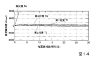
図14は、本第2実施例の実験結果を示しており、液状化被害低減構造による実験模型(第2対策T2、第3対策T3)、上記第1実施例の全方向対策による第1対策T1、無対策T0の場合において、地震後の傾斜増分(rad)を比較したものである。これによると、全方向対策(第1対策T1)の場合が最も傾斜の変動が小さいことを確認することができ、また第2対策T2及び第3対策T3の2方向のみの場合でも1/1500程度と小さな傾斜増分となることを確認することができる。このことから、液状化被害低減構造は、必ずしも全方向に設けられていることに限定されず、2方向対策でも全方向対策と同様の効果を得ることができる。 FIG. 14 shows the experimental results of the second embodiment. The experimental model with the liquefaction damage reducing structure (second countermeasure T2, third countermeasure T3), the first countermeasure by the omnidirectional countermeasure of the first embodiment. In the case of T1 and no countermeasure T0, the slope increment (rad) after the earthquake is compared. According to this, it can be confirmed that the variation in inclination is the smallest in the case of the omnidirectional measure (first measure T1), and even in the case of only the two directions of the second measure T2 and the third measure T3, 1/1500. It can be confirmed that the degree and the inclination increment are small. For this reason, the liquefaction damage reducing structure is not necessarily limited to being provided in all directions, and a two-way countermeasure can obtain the same effect as the omnidirectional countermeasure.
(第3実施例)
第3実施例は、上述した第5の実施の形態に相当する液状化被害低減構造の模型(図示省略)を使用して実験を行い、その効果を確認したものである。具体的に第3実施例の実験で使用する実験模型は、図12(b)に示す礫層部103に連通するとともに、液状化層102内で礫層部103から鉛直方向で下方に延びる透水性を有する複数の鉛直ドレーン(図示省略)が構造物101の外周部に沿う方向に所定間隔をあけて設けられており、全周ではなく上記第2実施例と同様に2方向対策としたもの(第4対策T4)である。鉛直ドレーンは、基礎(構造物101)の前後面(偏心荷重により荷重が大きい側を前面とする)の2方向対策のそれぞれに外径330mm(実換算)を3本ずつ配置し、ドレーン先端は、構造物101の底面から1.2m(実換算)とした。また、鉛直ドレーンは、3号珪砂を使用している。
このような実験模型を使用し、第1実施例と同様の条件で実験を行い、その効果を確認した。
(Third embodiment)
In the third example, an experiment was performed using a model (not shown) of a liquefaction damage reducing structure corresponding to the above-described fifth embodiment, and the effect was confirmed. Specifically, the experimental model used in the experiment of the third embodiment communicates with the
Using such an experimental model, an experiment was performed under the same conditions as in the first example, and the effect was confirmed.
図15は、本第3実施例の実験結果を示しており、液状化被害低減構造による実験模型(第4対策T4)、鉛直ドレーンを設けない構造(すなわち、上記第2実施例の2方向対策による第2対策T2)、及び無対策T0の場合において、地震後の傾斜増分(rad)を比較したものである。これによると、鉛直ドレーンを設ける第4対策T4でも傾斜増分の変動が小さいことを確認することができることから、液状化被害低減効果が得られることを確認することができる。 FIG. 15 shows the experimental results of the third embodiment. An experimental model (fourth countermeasure T4) using a liquefaction damage reducing structure and a structure without a vertical drain (that is, the two-way countermeasure of the second embodiment). In the case of the second countermeasure T2) and T0 without countermeasure, the slope increment (rad) after the earthquake is compared. According to this, it can be confirmed that even the fourth countermeasure T4 provided with the vertical drain has a small change in the inclination increment, so that the effect of reducing the liquefaction damage can be obtained.
以上、本発明による構造物の液状化被害低減構造、および液状化被害低減方法の実施の形態について説明したが、本発明は上記の実施の形態に限定されるものではなく、その趣旨を逸脱しない範囲で適宜変更可能である。
例えば、本実施の形態の礫層部3の層厚、深さ、鉛直ドレーン5の深さ方向の長さ、構造物基礎21の拡幅量(拡幅部22の面積)などは、構造物2の大きさ、重さ、地盤条件などを考慮して適宜設定される。例えば、礫層部3の敷設面積や鉛直ドレーンの設計については、本出願人が先に特願2011−166531により記載した方法などを用いることができる。
The embodiments of the structure liquefaction damage reducing structure and the liquefaction damage reducing method according to the present invention have been described above. However, the present invention is not limited to the above embodiments, and does not depart from the spirit of the present invention. The range can be changed as appropriate.
For example, the layer thickness and depth of the
また、本発明の液状化被害低減構造では、上述した実施の形態の液状化被害低減構造の各構成要素(拡幅部22、22A、突状部24、張出し部25、鉛直ドレーン5など)を適宜組み合わせることも可能である。例えば、上述した図4に示す第2の実施の形態による構造物基礎21の対向する2方向にそれぞれ拡幅部22が設けられ、拡幅部22が設けられない構造物基礎21の他の2方向には図7に示す第4の実施の形態に記載したブロック状の拡幅部22Aを設けるような構成とすることも可能である。また、第1の実施の形態の礫層部3の一部(例えば構造物基礎21の一辺部分に設けられる礫層部3のみに、図8に示す鉛直ドレーン5を設ける構成としてもよい。
Further, in the liquefaction damage reducing structure of the present invention, each component (the
なお、本発明は上述したように小規模構造物や既存構造物に適用することが好適ではあるが、それに限るものではなく、規模を問わず各種の構造物に広く適用できるものであるし、既存構造物に限らず新築構造物に対しても適用可能であることはいうまでもない。 As described above, the present invention is preferably applied to a small-scale structure or an existing structure, but is not limited thereto, and can be widely applied to various structures regardless of the scale. Needless to say, the present invention is not limited to existing structures.
その他、本発明の趣旨を逸脱しない範囲で、上記した実施の形態における構成要素を周知の構成要素に置き換えることは適宜可能である。 In addition, it is possible to appropriately replace the components in the above-described embodiments with known components without departing from the spirit of the present invention.
1、1A〜1G 液状化被害低減構造
2 構造物
3 礫層部
5 鉛直ドレーン
21 構造物基礎
22 拡幅部
24 突状部
25 張出し部
G 液状化地盤
DESCRIPTION OF
Claims (10)
平面視で前記構造物の構造物基礎の外周側のみに礫を敷設することにより形成され前記液状化地盤よりも透水係数が大きい排水機能を有する礫層部を設け、
該礫層部に前記構造物基礎の外周部分が接続されていることを特徴とする液状化被害低減構造。 A structure for reducing the damage to the structure when the liquefied ground is liquefied, targeting a structure constructed on the liquefied ground,
Provided with a gravel layer portion having a drainage function that is formed by laying gravel only on the outer peripheral side of the structure foundation of the structure in plan view and having a larger water permeability than the liquefied ground,
A structure for reducing liquefaction damage, wherein an outer peripheral portion of the structure foundation is connected to the gravel layer.
平面視で前記構造物の構造物基礎の外周側のみを掘削して礫を敷設することにより、前記液状化地盤よりも透水係数が大きい排水機能を有する礫層部を設ける工程と、
該礫層部に前記構造物基礎の外周部分を接続させる工程と、
を有することを特徴とする液状化被害低減方法。 A liquefaction damage reducing method for reducing damage to the structure when the liquefied ground is liquefied, targeting a structure constructed on a liquefied ground,
By digging only the outer peripheral side of the structure foundation of the structure in plan view and laying gravel, a step of providing a gravel layer portion having a drainage function having a larger hydraulic conductivity than the liquefied ground,
Connecting the outer periphery of the structure foundation to the gravel layer,
A liquefaction damage reducing method characterized by comprising:
Priority Applications (1)
| Application Number | Priority Date | Filing Date | Title |
|---|---|---|---|
| JP2013105379A JP6132144B2 (en) | 2012-05-21 | 2013-05-17 | Structure liquefaction damage reducing structure and liquefaction damage reducing method |
Applications Claiming Priority (3)
| Application Number | Priority Date | Filing Date | Title |
|---|---|---|---|
| JP2012115573 | 2012-05-21 | ||
| JP2012115573 | 2012-05-21 | ||
| JP2013105379A JP6132144B2 (en) | 2012-05-21 | 2013-05-17 | Structure liquefaction damage reducing structure and liquefaction damage reducing method |
Publications (2)
| Publication Number | Publication Date |
|---|---|
| JP2014001619A JP2014001619A (en) | 2014-01-09 |
| JP6132144B2 true JP6132144B2 (en) | 2017-05-24 |
Family
ID=50035031
Family Applications (1)
| Application Number | Title | Priority Date | Filing Date |
|---|---|---|---|
| JP2013105379A Active JP6132144B2 (en) | 2012-05-21 | 2013-05-17 | Structure liquefaction damage reducing structure and liquefaction damage reducing method |
Country Status (1)
| Country | Link |
|---|---|
| JP (1) | JP6132144B2 (en) |
Families Citing this family (3)
| Publication number | Priority date | Publication date | Assignee | Title |
|---|---|---|---|---|
| NZ624344A (en) | 2014-04-30 | 2014-05-30 | Ellsworth Stenswick Larry | A seismic isolation system |
| JP6544566B2 (en) * | 2015-05-01 | 2019-07-17 | 清水建設株式会社 | Countermeasures against liquefaction of existing structures |
| CN114960610B (en) * | 2022-04-25 | 2024-03-26 | 三明学院 | A composite foundation with single-component geopolymer reinforced soil and its construction method |
Family Cites Families (4)
| Publication number | Priority date | Publication date | Assignee | Title |
|---|---|---|---|---|
| JPH09316874A (en) * | 1996-05-27 | 1997-12-09 | Kubota Corp | Support pile as measure against liquefaction |
| JPH1018314A (en) * | 1996-07-02 | 1998-01-20 | Taisei Corp | Prevention of liquefaction of direct foundation of structure |
| JP3759301B2 (en) * | 1997-12-24 | 2006-03-22 | 大成建設株式会社 | Structural foundation reinforcement structure |
| JP5150519B2 (en) * | 2008-12-25 | 2013-02-20 | 五洋建設株式会社 | Iso-sink base plate structure |
-
2013
- 2013-05-17 JP JP2013105379A patent/JP6132144B2/en active Active
Also Published As
| Publication number | Publication date |
|---|---|
| JP2014001619A (en) | 2014-01-09 |
Similar Documents
| Publication | Publication Date | Title |
|---|---|---|
| CN105953078B (en) | The protective device of high-pressure gas pipeline and guard method | |
| JP5471797B2 (en) | Seismic reinforcement structure of revetment structure and existing revetment structure | |
| JP2017166314A (en) | Cofferdam structure | |
| JP2008190116A (en) | Liquefaction countermeasure structure of foundation ground of building | |
| JP6132144B2 (en) | Structure liquefaction damage reducing structure and liquefaction damage reducing method | |
| JP5382900B2 (en) | How to prevent underground structures from floating due to liquefaction | |
| JP2010133206A (en) | Structure and construction method for newly-built structure using existing pile | |
| JP6681115B2 (en) | Method for designing the structure for countermeasures against liquefaction of ground | |
| KR101902791B1 (en) | Under ground structure construction method using composite steel pile and under ground structure therewith | |
| JP5777435B2 (en) | Reinforcement method for foundations for small buildings | |
| JP6277755B2 (en) | Ground improvement method and ground improvement system | |
| JP6238088B2 (en) | Improved ground and ground improvement method | |
| JP2023534788A (en) | Rapid consolidation and compaction methods for soil improvement of various layers of intermediate geological material within soils and soil sediments | |
| JP5877482B2 (en) | Structure for reducing liquefaction damage of structures | |
| JP5975726B2 (en) | Ground structure and ground improvement method | |
| JP5822201B2 (en) | Basic structure of the structure | |
| JP2006342666A (en) | Method for antiseismic reinforcement of structure | |
| JP2009068203A (en) | Earth retaining wall composed of horizontal sheathing with soldier beam, and cut-off structure, construction method and cut-off method for the earth retaining wall | |
| JP6259271B2 (en) | Caisson installation method and underground column body group | |
| JP4475116B2 (en) | Vertical shaft structure and its construction method | |
| JP5850545B2 (en) | Improved ground structure near the pole and ground improvement method | |
| JP4868589B2 (en) | Support structure for construction foundation and construction method | |
| JP7469608B2 (en) | Support structure, gravity breakwater and construction method of gravity breakwater | |
| JP5468165B1 (en) | Sand sand control method | |
| KR101089729B1 (en) | Pier foundation wall |
Legal Events
| Date | Code | Title | Description |
|---|---|---|---|
| A621 | Written request for application examination |
Free format text: JAPANESE INTERMEDIATE CODE: A621 Effective date: 20151118 |
|
| A977 | Report on retrieval |
Free format text: JAPANESE INTERMEDIATE CODE: A971007 Effective date: 20160826 |
|
| A131 | Notification of reasons for refusal |
Free format text: JAPANESE INTERMEDIATE CODE: A131 Effective date: 20160830 |
|
| A521 | Written amendment |
Free format text: JAPANESE INTERMEDIATE CODE: A523 Effective date: 20161025 |
|
| TRDD | Decision of grant or rejection written | ||
| A01 | Written decision to grant a patent or to grant a registration (utility model) |
Free format text: JAPANESE INTERMEDIATE CODE: A01 Effective date: 20170314 |
|
| A61 | First payment of annual fees (during grant procedure) |
Free format text: JAPANESE INTERMEDIATE CODE: A61 Effective date: 20170405 |
|
| R150 | Certificate of patent or registration of utility model |
Ref document number: 6132144 Country of ref document: JP Free format text: JAPANESE INTERMEDIATE CODE: R150 |