JP6056830B2 - 電気コネクタ及び電気コネクタ装置 - Google Patents
電気コネクタ及び電気コネクタ装置 Download PDFInfo
- Publication number
- JP6056830B2 JP6056830B2 JP2014208761A JP2014208761A JP6056830B2 JP 6056830 B2 JP6056830 B2 JP 6056830B2 JP 2014208761 A JP2014208761 A JP 2014208761A JP 2014208761 A JP2014208761 A JP 2014208761A JP 6056830 B2 JP6056830 B2 JP 6056830B2
- Authority
- JP
- Japan
- Prior art keywords
- connector
- fitting
- contact member
- holding member
- ground connection
- Prior art date
- Legal status (The legal status is an assumption and is not a legal conclusion. Google has not performed a legal analysis and makes no representation as to the accuracy of the status listed.)
- Active
Links
- 230000013011 mating Effects 0.000 claims description 45
- 230000008054 signal transmission Effects 0.000 claims description 17
- 230000008878 coupling Effects 0.000 claims description 16
- 238000010168 coupling process Methods 0.000 claims description 16
- 238000005859 coupling reaction Methods 0.000 claims description 16
- 239000000758 substrate Substances 0.000 claims description 7
- 230000005405 multipole Effects 0.000 claims 1
- 239000004020 conductor Substances 0.000 description 11
- 230000005540 biological transmission Effects 0.000 description 3
- 210000002105 tongue Anatomy 0.000 description 3
- 238000009413 insulation Methods 0.000 description 2
- 239000002184 metal Substances 0.000 description 2
- 241000257465 Echinoidea Species 0.000 description 1
- 238000005452 bending Methods 0.000 description 1
- 238000007689 inspection Methods 0.000 description 1
- 239000000463 material Substances 0.000 description 1
- 230000004048 modification Effects 0.000 description 1
- 238000012986 modification Methods 0.000 description 1
- 238000000465 moulding Methods 0.000 description 1
- 230000002093 peripheral effect Effects 0.000 description 1
- 230000005855 radiation Effects 0.000 description 1
- 230000001105 regulatory effect Effects 0.000 description 1
- 230000000630 rising effect Effects 0.000 description 1
- 238000005476 soldering Methods 0.000 description 1
- 238000003466 welding Methods 0.000 description 1
Images


Classifications
-
- H—ELECTRICITY
- H01—ELECTRIC ELEMENTS
- H01R—ELECTRICALLY-CONDUCTIVE CONNECTIONS; STRUCTURAL ASSOCIATIONS OF A PLURALITY OF MUTUALLY-INSULATED ELECTRICAL CONNECTING ELEMENTS; COUPLING DEVICES; CURRENT COLLECTORS
- H01R13/00—Details of coupling devices of the kinds covered by groups H01R12/70 or H01R24/00 - H01R33/00
- H01R13/648—Protective earth or shield arrangements on coupling devices, e.g. anti-static shielding
- H01R13/652—Protective earth or shield arrangements on coupling devices, e.g. anti-static shielding with earth pin, blade or socket
-
- H—ELECTRICITY
- H01—ELECTRIC ELEMENTS
- H01R—ELECTRICALLY-CONDUCTIVE CONNECTIONS; STRUCTURAL ASSOCIATIONS OF A PLURALITY OF MUTUALLY-INSULATED ELECTRICAL CONNECTING ELEMENTS; COUPLING DEVICES; CURRENT COLLECTORS
- H01R12/00—Structural associations of a plurality of mutually-insulated electrical connecting elements, specially adapted for printed circuits, e.g. printed circuit boards [PCB], flat or ribbon cables, or like generally planar structures, e.g. terminal strips, terminal blocks; Coupling devices specially adapted for printed circuits, flat or ribbon cables, or like generally planar structures; Terminals specially adapted for contact with, or insertion into, printed circuits, flat or ribbon cables, or like generally planar structures
- H01R12/70—Coupling devices
- H01R12/77—Coupling devices for flexible printed circuits, flat or ribbon cables or like structures
- H01R12/771—Details
- H01R12/775—Ground or shield arrangements
-
- H—ELECTRICITY
- H01—ELECTRIC ELEMENTS
- H01R—ELECTRICALLY-CONDUCTIVE CONNECTIONS; STRUCTURAL ASSOCIATIONS OF A PLURALITY OF MUTUALLY-INSULATED ELECTRICAL CONNECTING ELEMENTS; COUPLING DEVICES; CURRENT COLLECTORS
- H01R12/00—Structural associations of a plurality of mutually-insulated electrical connecting elements, specially adapted for printed circuits, e.g. printed circuit boards [PCB], flat or ribbon cables, or like generally planar structures, e.g. terminal strips, terminal blocks; Coupling devices specially adapted for printed circuits, flat or ribbon cables, or like generally planar structures; Terminals specially adapted for contact with, or insertion into, printed circuits, flat or ribbon cables, or like generally planar structures
- H01R12/70—Coupling devices
- H01R12/77—Coupling devices for flexible printed circuits, flat or ribbon cables or like structures
- H01R12/79—Coupling devices for flexible printed circuits, flat or ribbon cables or like structures connecting to rigid printed circuits or like structures
-
- H—ELECTRICITY
- H01—ELECTRIC ELEMENTS
- H01R—ELECTRICALLY-CONDUCTIVE CONNECTIONS; STRUCTURAL ASSOCIATIONS OF A PLURALITY OF MUTUALLY-INSULATED ELECTRICAL CONNECTING ELEMENTS; COUPLING DEVICES; CURRENT COLLECTORS
- H01R12/00—Structural associations of a plurality of mutually-insulated electrical connecting elements, specially adapted for printed circuits, e.g. printed circuit boards [PCB], flat or ribbon cables, or like generally planar structures, e.g. terminal strips, terminal blocks; Coupling devices specially adapted for printed circuits, flat or ribbon cables, or like generally planar structures; Terminals specially adapted for contact with, or insertion into, printed circuits, flat or ribbon cables, or like generally planar structures
- H01R12/70—Coupling devices
- H01R12/77—Coupling devices for flexible printed circuits, flat or ribbon cables or like structures
- H01R12/771—Details
- H01R12/774—Retainers
-
- H—ELECTRICITY
- H01—ELECTRIC ELEMENTS
- H01R—ELECTRICALLY-CONDUCTIVE CONNECTIONS; STRUCTURAL ASSOCIATIONS OF A PLURALITY OF MUTUALLY-INSULATED ELECTRICAL CONNECTING ELEMENTS; COUPLING DEVICES; CURRENT COLLECTORS
- H01R13/00—Details of coupling devices of the kinds covered by groups H01R12/70 or H01R24/00 - H01R33/00
- H01R13/02—Contact members
- H01R13/04—Pins or blades for co-operation with sockets
-
- H—ELECTRICITY
- H01—ELECTRIC ELEMENTS
- H01R—ELECTRICALLY-CONDUCTIVE CONNECTIONS; STRUCTURAL ASSOCIATIONS OF A PLURALITY OF MUTUALLY-INSULATED ELECTRICAL CONNECTING ELEMENTS; COUPLING DEVICES; CURRENT COLLECTORS
- H01R13/00—Details of coupling devices of the kinds covered by groups H01R12/70 or H01R24/00 - H01R33/00
- H01R13/62—Means for facilitating engagement or disengagement of coupling parts or for holding them in engagement
- H01R13/629—Additional means for facilitating engagement or disengagement of coupling parts, e.g. aligning or guiding means, levers, gas pressure electrical locking indicators, manufacturing tolerances
- H01R13/62933—Comprising exclusively pivoting lever
- H01R13/62955—Pivoting lever comprising supplementary/additional locking means
-
- H—ELECTRICITY
- H01—ELECTRIC ELEMENTS
- H01R—ELECTRICALLY-CONDUCTIVE CONNECTIONS; STRUCTURAL ASSOCIATIONS OF A PLURALITY OF MUTUALLY-INSULATED ELECTRICAL CONNECTING ELEMENTS; COUPLING DEVICES; CURRENT COLLECTORS
- H01R13/00—Details of coupling devices of the kinds covered by groups H01R12/70 or H01R24/00 - H01R33/00
- H01R13/62—Means for facilitating engagement or disengagement of coupling parts or for holding them in engagement
- H01R13/639—Additional means for holding or locking coupling parts together, after engagement, e.g. separate keylock, retainer strap
-
- H—ELECTRICITY
- H01—ELECTRIC ELEMENTS
- H01R—ELECTRICALLY-CONDUCTIVE CONNECTIONS; STRUCTURAL ASSOCIATIONS OF A PLURALITY OF MUTUALLY-INSULATED ELECTRICAL CONNECTING ELEMENTS; COUPLING DEVICES; CURRENT COLLECTORS
- H01R13/00—Details of coupling devices of the kinds covered by groups H01R12/70 or H01R24/00 - H01R33/00
- H01R13/648—Protective earth or shield arrangements on coupling devices, e.g. anti-static shielding
- H01R13/658—High frequency shielding arrangements, e.g. against EMI [Electro-Magnetic Interference] or EMP [Electro-Magnetic Pulse]
- H01R13/6591—Specific features or arrangements of connection of shield to conductive members
- H01R13/6594—Specific features or arrangements of connection of shield to conductive members the shield being mounted on a PCB and connected to conductive members
- H01R13/6595—Specific features or arrangements of connection of shield to conductive members the shield being mounted on a PCB and connected to conductive members with separate members fixing the shield to the PCB
Landscapes
- Details Of Connecting Devices For Male And Female Coupling (AREA)
- Coupling Device And Connection With Printed Circuit (AREA)
Description
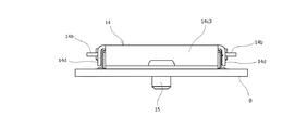
まず、図1〜図13に表された本発明の一実施形態にかかる電気コネクタ装置は、信号伝送媒体を構成する同軸ケーブルSCの端末部分が連結された第1コネクタとしてのプラグコネクタ1と、印刷配線基板B上に実装された第2コネクタとしてのリセプタクルコネクタ2と、を備えた水平嵌合型の電気コネクタ装置であって、図1のようにプラグコネクタ(第1コネクタ)1が、嵌合の相手コネクタとしてのリセプタクルコネクタ(第2コネクタ)2に対して略水平方向に対向するように配置された後に、印刷配線基板Bの表面に沿ってリセプタクルコネクタ2側に近接するように水平に移動されることによって、図2のようにプラグコネクタ1の先端側部分が、リセプタクルコネクタ2の開口部を通して内部に差し込まれ、それによって両コネクタ1,2同士が嵌合状態になされる。
一方、これらのプラグコネクタ(第1コネクタ)1、及びリセプタクルコネクタ(第2コネクタ)2の両電気コネクタは、前述したように導電コンタクト部材(導電端子)12,22の多極配列方向(コネクタ長手方向)に細長状に延在する細長状の絶縁ハウジング(コネクタ本体部)11,21をそれぞれ備えているが、これらの絶縁ハウジング11,21に取り付けられた導電コンタクト部材12,22は、前述した上下2段の同軸ケーブルSC,SCにそれぞれ対応して互いに形状が異なるように形成されており、多極配列方向(コネクタ長手方向)に隣接するもの同士の形状が互いに異なる2種類の導電コンタクト部材12,22が交互に配列された構成になされている。
一方、プラグコネクタ(第1コネクタ)1及びリセプタクルコネクタ(第2コネクタ)2に設けられた各絶縁ハウジング(コネクタ本体部)11,21の外表面は、薄板状金属部材を適宜の形状に折曲形成した導電性シェル(シールドシェル部材)13及び23によりそれぞれ覆われている。これらの導電性シェル13,23は、各コネクタ1,2の内部に形成される信号伝送回路及びグランド回路を覆うことによって電磁遮蔽性(シールド性)を持たせる部材として装着されたものであるが、グランド回路の一部を構成する部材でもある。
これに対して、図1、および図2に示される様に、相手コネクタであるリセプタクルコネクタ(第2コネクタ)2に設けられた導電性シェル(シールドシェル部材)23には、コネクタ長手方向の両端部分に外方側から挟むようにしてホールドダウン23aがそれぞれ設けられている。それらのホールドダウン23aは、コネクタ長手方向の片側部分において一対ずつ設けられており、それらの各ホールドダウン23aの下端縁部が、印刷配線基板B上に形成されたグランド接続用の導電路に対して半田接合され、それによってグランド回路の電気的な接続が行われるとともに、リセプタクルコネクタ2の全体が強固に固定されるようになっている。
次に、図2から図4に示される様に、プラグコネクタ(第1コネクタ)1がリセプタクルコネクタ(第2コネクタ)2に嵌合された両コネクタ1,2同士の嵌合状態は、プラグコネクタ1に設けられた嵌合保持部材14の保持力によって維持されるようになっている。なお、リセプタクルコネクタ2に嵌合したプラグコネクタ1を、リセプタクルコネクタ2から抜去する際においては、嵌合保持部材14を開放させる操作が行われることによって両コネクタ1,2同士が抜去可能な状態になされる。
11 絶縁ハウジング(コネクタ本体部)
11a 本体支持部
11b 嵌合突部
12 導電コンタクト部材(第1コンタクト部材)
12a 端子電極部
13 導電性シェル
13a グランド接続舌片
13d 軸受け部
13e バネ規制部材
14 嵌合保持部材
14a 回動軸部
14b 連結腕部
14c シールドプレート
14c1 上面側シールドカバー
14c2 背面側シールドカバー
14c3 グランド接続板(グランド接続部)
14c4板バネ状部材
14c5 グランド固定穴
14d ロック板
14e ロック係止穴
15 固定ネジ(機械的結合手段)
GB グランドバー
GC グランドコンタクト
SC 同軸ケーブル(信号伝送媒体)
SCa ケーブル中心導体(信号線)
SCb ケーブル外部導体(シールド線)
2 リセプタクルコネクタ(第2コネクタ)
21 絶縁ハウジング(コネクタ本体部)
22 導電コンタクト部材(第2コンタクト部材)
22a 基板接続脚部
22b 接点凸部
23 導電性シェル(コネクタ本体部)
23a ホールドダウン
23a1 ロック部
23b 上側シェル板
B 印刷配線基板
B1 グランド接続用の導電路
B2 基板固定穴
Claims (8)
- 信号伝送媒体の端末部分がコネクタ本体部に連結された状態で、配線基板の表面上に実装された相手コネクタに嵌合されて使用されるものであって、
前記コネクタ本体部に取り付けられたコンタクト部材が前記信号伝送媒体に接続されるとともに、前記相手コネクタに取り付けられた相手コンタクト部材の基板接続脚部が前記配線基板に接続され、前記相手コネクタとの嵌合時に、前記コンタクト部材が前記相手コンタクト部材に接触することにより電気的な接続が行われる一方、
前記コネクタ本体部に回動可能に設けられた嵌合保持部材が、前記相手コネクタとの嵌合時に嵌合開放位置から嵌合作用位置まで回動されることによって、前記相手コネクタとの嵌合状態が維持されるように構成された電気コネクタにおいて、
前記嵌合保持部材には、当該嵌合保持部材が嵌合作用位置まで回動された際に、少なくとも前記相手コンタクト部材の基板接続脚部を覆うシールドカバーが設けられている一方、
前記配線基板の表面部分であって前記相手コンタクト部材の基板接続脚部が接続される部位の近傍位置に形成されたグランド接続用の導電路に対して、前記嵌合保持部材に設けられたグランド接続部が、前記嵌合保持部材が嵌合作用位置まで回動された際に接触する構成になされたものであって、
前記嵌合保持部材のグランド接続部が、前記シールドカバーに対して一体的に連続する板状部材からなり、
当該グランド接続部を構成している板状部材は、前記嵌合保持部材が嵌合作用位置まで回動された際に、前記配線基板の表面部分であって前記グランド接続用の導電路及びその周囲を含む領域を覆う配置関係になされていることを特徴とする電気コネクタ。 - 信号伝送媒体の端末部分が連結される第1コネクタと、配線基板の表面上に実装された状態で前記第1コネクタが嵌合される第2コネクタと、を備え、
前記第1コネクタに取り付けられた第1コンタクト部材が前記信号伝送媒体に接続されるとともに、前記第2コネクタに取り付けられた第2コンタクト部材の基板接続脚部が前記配線基板に接続され、前記第1及び第2コネクタ同士の嵌合時に、前記第1コンタクト部材が前記第2コンタクト部材に接触することにより電気的な接続が行われる一方、
前記第1コネクタに回動可能に設けられた嵌合保持部材が、前記第2コネクタとの嵌合時に嵌合開放位置から嵌合作用位置まで回動されることによって、前記第2コネクタとの嵌合状態が維持されるように構成された電気コネクタ装置において、
前記第1コネクタの嵌合保持部材には、当該嵌合保持部材が嵌合作用位置まで回動された際に、少なくとも前記第2コンタクト部材の基板接続脚部を覆うシールドカバーが設けられている一方、
前記配線基板の表面部分であって前記第2コンタクト部材の基板接続脚部が接続される部位の近傍位置にグランド接続用の導電路が形成され、
その配線基板のグランド接続用導電路に対して、前記嵌合保持部材に設けられたグランド接続部が、前記嵌合保持部材が嵌合作用位置まで回動された際に接触する構成になされたものであって、
前記嵌合保持部材のグランド接続部が、前記シールドプレートに対して一体的に連続する板状部材からなり、
当該グランド接続部は、前記嵌合保持部材が嵌合作用位置まで回動された際に、前記配線基板の表面部分であって前記グランド接続用の導電路及びその周囲を含む領域を覆う配置関係になされていることを特徴とする電気コネクタ装置。 - 前記嵌合保持部材に設けられたグランド接続部が、前記配線基板に対して機械的結合手段により固定されるように構成されていることを特徴とする請求項1記載の電気コネクタ又は請求項2記載の電気コネクタ装置。
- 前記グランド接続部が、前記グランド接続用の導電路に対して弾性的に接触する複数の板バネ状部材を備えているとともに、
前記機械的結合手段が、前記複数の板バネ状部材の間に挟まれて配置されていることを特徴とする請求項3記載の電気コネクタ又は電気コネクタ装置。 - 前記シールドカバーが、前記配線基板の外方側から前記相手コンタクト部材又は前記第2コンタクト部材を覆うように形成されたものであって、
前記シールドカバーは、前記相手コンタクト部材又は前記第2コンタクト部材を外方側から覆う上面側シールドカバーと、その上面側シールドカバーから前記基板接続脚部の外方側を覆うように延出する背面側カバーと、を備えていることを特徴とする請求項1記載の電気コネクタ又は請求項2記載の電気コネクタ装置。 - 前記相手コネクタ又は第2コネクタに、当該相手コネクタ又は第2コネクタの外表面を覆うシールドシェル部材が装着されたものであって、
前記シールドシェル部材と前記シールドカバーとにより、前記相手コンタクト部材又は前記第2コンタクト部材が前記配線基板の外方側から覆われる構成になされていることを特徴とする請求項1記載の電気コネクタ又は請求項2記載の電気コネクタ装置。 - 前記前記相手コネクタ又は第2コネクタには、前記嵌合保持部材を嵌合作用位置に保持するロック部が設けられていることを特徴とする請求項1記載の電気コネクタ又は請求項2記載の電気コネクタ装置。
- 前記信号伝送媒体が、上下の2段にわたって多極状に配置され、かつそれら2段の信号伝送媒体が、多極配列の方向において互いに位置ズレした配置関係になされた状態で、2種類のコンタクト部材又は第1コンタクト部材に連結されたものであって、
前記2種類のコンタクト部材又は第1コンタクト部材に対して弾性的に接触する2種類の相手コンタクト部材又は第2コンタクト部材の基板接続脚部が、配線基板上に接続される構成になされていることを特徴とする請求項1記載の電気コネクタ又は請求項2記載の電気コネクタ装置。
Priority Applications (7)
| Application Number | Priority Date | Filing Date | Title |
|---|---|---|---|
| JP2014208761A JP6056830B2 (ja) | 2014-10-10 | 2014-10-10 | 電気コネクタ及び電気コネクタ装置 |
| KR1020150123628A KR101735945B1 (ko) | 2014-10-10 | 2015-09-01 | 전기 커넥터 및 전기 커넥터 장치 |
| US14/859,509 US9397447B2 (en) | 2014-10-10 | 2015-09-21 | Electrical connector and electrical connector device |
| DE102015116126.5A DE102015116126A1 (de) | 2014-10-10 | 2015-09-24 | Elektrischer Verbinder und elektrische Verbindereinrichtung |
| CN201510615923.2A CN105514708B (zh) | 2014-10-10 | 2015-09-24 | 电连接器及电连接器装置 |
| TW104131586A TWI596845B (zh) | 2014-10-10 | 2015-09-24 | 電連接器及電連接器裝置 |
| FR1559628A FR3027163B1 (fr) | 2014-10-10 | 2015-10-09 | Connecteur electrique et dispositif de connecteur electrique |
Applications Claiming Priority (1)
| Application Number | Priority Date | Filing Date | Title |
|---|---|---|---|
| JP2014208761A JP6056830B2 (ja) | 2014-10-10 | 2014-10-10 | 電気コネクタ及び電気コネクタ装置 |
Publications (2)
| Publication Number | Publication Date |
|---|---|
| JP2016081591A JP2016081591A (ja) | 2016-05-16 |
| JP6056830B2 true JP6056830B2 (ja) | 2017-01-11 |
Family
ID=55587855
Family Applications (1)
| Application Number | Title | Priority Date | Filing Date |
|---|---|---|---|
| JP2014208761A Active JP6056830B2 (ja) | 2014-10-10 | 2014-10-10 | 電気コネクタ及び電気コネクタ装置 |
Country Status (7)
| Country | Link |
|---|---|
| US (1) | US9397447B2 (ja) |
| JP (1) | JP6056830B2 (ja) |
| KR (1) | KR101735945B1 (ja) |
| CN (1) | CN105514708B (ja) |
| DE (1) | DE102015116126A1 (ja) |
| FR (1) | FR3027163B1 (ja) |
| TW (1) | TWI596845B (ja) |
Families Citing this family (29)
| Publication number | Priority date | Publication date | Assignee | Title |
|---|---|---|---|---|
| JP6052268B2 (ja) * | 2014-11-28 | 2016-12-27 | 第一精工株式会社 | 電気コネクタ及び電気コネクタ装置 |
| KR102566675B1 (ko) * | 2016-05-19 | 2023-08-11 | 엘에스엠트론 주식회사 | 커넥터 |
| CN107623203B (zh) * | 2016-07-13 | 2019-07-26 | 洪瑞聪 | 电连接器的结构及其组装方法 |
| JP7035015B2 (ja) | 2016-08-15 | 2022-03-14 | サムテック インコーポレイテッド | 相互接続システムのためのバックアウト防止ラッチ |
| US9935412B1 (en) * | 2017-01-06 | 2018-04-03 | GM Global Technology Operations LLC | Electrical connector assembly and a product that includes the electrical connector assembly |
| JP2018129150A (ja) * | 2017-02-07 | 2018-08-16 | 第一精工株式会社 | 電気コネクタ |
| US11196195B2 (en) | 2017-04-10 | 2021-12-07 | Samtec, Inc. | Interconnect system having retention features |
| CN109428235B (zh) * | 2017-08-22 | 2023-10-24 | 正凌精密工业(广东)有限公司 | 高速连接器及连接器组合 |
| USD886066S1 (en) | 2017-12-06 | 2020-06-02 | Samtec, Inc. | Securement member of electrical connector |
| JP6807028B2 (ja) * | 2017-12-20 | 2021-01-06 | I−Pex株式会社 | 電気コネクタ及び電気コネクタの接続構造 |
| CN109980444B (zh) * | 2017-12-27 | 2021-11-19 | 富士康(昆山)电脑接插件有限公司 | 电连接器 |
| DE102019110695A1 (de) * | 2018-04-27 | 2019-10-31 | Panasonic Intellectual Property Management Co., Ltd. | Verbinder und verbinderanschluss zur verwendung in dem verbinder |
| JP6741040B2 (ja) * | 2018-05-10 | 2020-08-19 | 第一精工株式会社 | ケーブルコネクタ装置 |
| JP6658798B2 (ja) * | 2018-06-05 | 2020-03-04 | 第一精工株式会社 | 電気コネクタ及びコネクタ装置 |
| CN109411957B (zh) * | 2018-06-05 | 2023-11-14 | 温州意华接插件股份有限公司 | 高速互连组件 |
| JP7108531B2 (ja) * | 2018-12-27 | 2022-07-28 | モレックス エルエルシー | コネクタ組立体 |
| DE102019100219A1 (de) * | 2019-01-07 | 2020-07-09 | Weidmüller Interface GmbH & Co. KG | Steckverbindung mit Schirmauflage |
| CN109659773B (zh) * | 2019-01-18 | 2023-11-24 | 江苏联炜诚电子科技有限公司 | 电连接器及具有该电连接器的电连接器组合 |
| CN112018546B (zh) * | 2019-05-29 | 2021-12-10 | 上海莫仕连接器有限公司 | 插座连接器及连接器组合 |
| JP7099993B2 (ja) * | 2019-05-30 | 2022-07-12 | 矢崎総業株式会社 | コネクタ |
| JP7203700B2 (ja) | 2019-07-24 | 2023-01-13 | 株式会社デンソーテン | コネクタシールドの取付構造 |
| CN112563782A (zh) * | 2019-09-25 | 2021-03-26 | 连展科技电子(昆山)有限公司 | 双排焊线结构 |
| JP7360918B2 (ja) * | 2019-12-06 | 2023-10-13 | イリソ電子工業株式会社 | コネクタ |
| TWM599071U (zh) * | 2020-03-12 | 2020-07-21 | 連展科技股份有限公司 | 單排焊線結構 |
| DE102020203971A1 (de) * | 2020-03-26 | 2021-09-30 | Fraunhofer-Gesellschaft zur Förderung der angewandten Forschung eingetragener Verein | Hochfrequenzanordnung mit zwei miteinander verbundenen Hochfrequenzkomponenten |
| KR20210127356A (ko) * | 2020-04-14 | 2021-10-22 | 삼성전자주식회사 | 접속 장치 및 그를 포함하는 전자 장치 |
| CN113675650A (zh) * | 2020-05-13 | 2021-11-19 | 日本航空电子工业株式会社 | 连接器 |
| CN111952792A (zh) * | 2020-08-21 | 2020-11-17 | 苏州浪潮智能科技有限公司 | 一种连接器及服务器 |
| US20240372301A1 (en) * | 2021-03-29 | 2024-11-07 | 3M Innovative Properties Company | Shielded connector assembly |
Family Cites Families (13)
| Publication number | Priority date | Publication date | Assignee | Title |
|---|---|---|---|---|
| US5123851A (en) * | 1991-03-11 | 1992-06-23 | Apple Computer, Inc. | Integrated connector module with conductive elastomeric contacts |
| JPH11345652A (ja) * | 1998-06-03 | 1999-12-14 | Amp Japan Ltd | カードコネクタ |
| US6152754A (en) * | 1999-12-21 | 2000-11-28 | Masimo Corporation | Circuit board based cable connector |
| JP4391975B2 (ja) | 2005-09-08 | 2009-12-24 | ヒロセ電機株式会社 | 電気コネクタ |
| TWM294134U (en) * | 2006-03-01 | 2006-07-11 | Proconn Technology Co Ltd | Fixation structure improvement of connector |
| CN101114745A (zh) * | 2006-07-28 | 2008-01-30 | 佛山市顺德区顺达电脑厂有限公司 | 电连接器电磁屏蔽结构 |
| US8133360B2 (en) * | 2007-12-20 | 2012-03-13 | Applied Materials, Inc. | Prediction and compensation of erosion in a magnetron sputtering target |
| JP4922420B2 (ja) * | 2010-02-23 | 2012-04-25 | 日本航空電子工業株式会社 | コネクタ組立体 |
| JP5516040B2 (ja) * | 2010-05-07 | 2014-06-11 | 第一精工株式会社 | 電気コネクタ及び電気コネクタ組立体 |
| JP5182334B2 (ja) * | 2010-08-02 | 2013-04-17 | 第一精工株式会社 | 電気コネクタ |
| JP5594053B2 (ja) * | 2010-10-22 | 2014-09-24 | 第一精工株式会社 | 電気コネクタ及びその組立体 |
| JP5813349B2 (ja) * | 2011-03-29 | 2015-11-17 | 日本航空電子工業株式会社 | コネクタ及び接続対象物 |
| CN103247913A (zh) * | 2013-04-25 | 2013-08-14 | 连展科技电子(昆山)有限公司 | 快扣式板对板连接器组件 |
-
2014
- 2014-10-10 JP JP2014208761A patent/JP6056830B2/ja active Active
-
2015
- 2015-09-01 KR KR1020150123628A patent/KR101735945B1/ko active IP Right Grant
- 2015-09-21 US US14/859,509 patent/US9397447B2/en active Active
- 2015-09-24 DE DE102015116126.5A patent/DE102015116126A1/de not_active Ceased
- 2015-09-24 TW TW104131586A patent/TWI596845B/zh not_active IP Right Cessation
- 2015-09-24 CN CN201510615923.2A patent/CN105514708B/zh active Active
- 2015-10-09 FR FR1559628A patent/FR3027163B1/fr not_active Expired - Fee Related
Also Published As
| Publication number | Publication date |
|---|---|
| CN105514708A (zh) | 2016-04-20 |
| CN105514708B (zh) | 2018-04-03 |
| US9397447B2 (en) | 2016-07-19 |
| KR20160042759A (ko) | 2016-04-20 |
| TWI596845B (zh) | 2017-08-21 |
| FR3027163A1 (fr) | 2016-04-15 |
| JP2016081591A (ja) | 2016-05-16 |
| FR3027163B1 (fr) | 2018-04-20 |
| DE102015116126A1 (de) | 2016-04-14 |
| TW201622270A (zh) | 2016-06-16 |
| KR101735945B1 (ko) | 2017-05-15 |
| US20160104971A1 (en) | 2016-04-14 |
Similar Documents
| Publication | Publication Date | Title |
|---|---|---|
| JP6056830B2 (ja) | 電気コネクタ及び電気コネクタ装置 | |
| JP6052268B2 (ja) | 電気コネクタ及び電気コネクタ装置 | |
| JP6225941B2 (ja) | 電気コネクタ及び電気コネクタ装置 | |
| JP5516040B2 (ja) | 電気コネクタ及び電気コネクタ組立体 | |
| JP6299733B2 (ja) | 電気コネクタ | |
| JP2008016212A (ja) | 電気コネクタ | |
| WO2011086857A1 (ja) | 電気コネクタ及び電気コネクタ組立体 | |
| JP6442964B2 (ja) | 電気コネクタ | |
| TWI675514B (zh) | 插座連接器 | |
| CN103094781B (zh) | 电连接器以及电连接器组装体 | |
| TWI451640B (zh) | Electrical connector and electrical connector assembly | |
| KR101296699B1 (ko) | 전기 커넥터 및 전기 커넥터 조립체 | |
| JP2017199466A (ja) | 電気コネクタ |
Legal Events
| Date | Code | Title | Description |
|---|---|---|---|
| A977 | Report on retrieval |
Free format text: JAPANESE INTERMEDIATE CODE: A971007 Effective date: 20160815 |
|
| A131 | Notification of reasons for refusal |
Free format text: JAPANESE INTERMEDIATE CODE: A131 Effective date: 20160823 |
|
| A521 | Request for written amendment filed |
Free format text: JAPANESE INTERMEDIATE CODE: A523 Effective date: 20161021 |
|
| TRDD | Decision of grant or rejection written | ||
| A01 | Written decision to grant a patent or to grant a registration (utility model) |
Free format text: JAPANESE INTERMEDIATE CODE: A01 Effective date: 20161108 |
|
| A61 | First payment of annual fees (during grant procedure) |
Free format text: JAPANESE INTERMEDIATE CODE: A61 Effective date: 20161121 |
|
| R150 | Certificate of patent or registration of utility model |
Ref document number: 6056830 Country of ref document: JP Free format text: JAPANESE INTERMEDIATE CODE: R150 |
|
| R250 | Receipt of annual fees |
Free format text: JAPANESE INTERMEDIATE CODE: R250 |
|
| R250 | Receipt of annual fees |
Free format text: JAPANESE INTERMEDIATE CODE: R250 |
|
| R250 | Receipt of annual fees |
Free format text: JAPANESE INTERMEDIATE CODE: R250 |
|
| R250 | Receipt of annual fees |
Free format text: JAPANESE INTERMEDIATE CODE: R250 |
|
| R250 | Receipt of annual fees |
Free format text: JAPANESE INTERMEDIATE CODE: R250 |
|
| R250 | Receipt of annual fees |
Free format text: JAPANESE INTERMEDIATE CODE: R250 |