JP6029182B2 - Method for manufacturing knit components - Google Patents
Method for manufacturing knit components Download PDFInfo
- Publication number
- JP6029182B2 JP6029182B2 JP2013558077A JP2013558077A JP6029182B2 JP 6029182 B2 JP6029182 B2 JP 6029182B2 JP 2013558077 A JP2013558077 A JP 2013558077A JP 2013558077 A JP2013558077 A JP 2013558077A JP 6029182 B2 JP6029182 B2 JP 6029182B2
- Authority
- JP
- Japan
- Prior art keywords
- feeder
- yarn
- knit
- plane
- arm
- Prior art date
- Legal status (The legal status is an assumption and is not a legal conclusion. Google has not performed a legal analysis and makes no representation as to the accuracy of the status listed.)
- Active
Links
Images


Classifications
-
- D—TEXTILES; PAPER
- D04—BRAIDING; LACE-MAKING; KNITTING; TRIMMINGS; NON-WOVEN FABRICS
- D04B—KNITTING
- D04B1/00—Weft knitting processes for the production of fabrics or articles not dependent on the use of particular machines; Fabrics or articles defined by such processes
- D04B1/10—Patterned fabrics or articles
- D04B1/12—Patterned fabrics or articles characterised by thread material
- D04B1/123—Patterned fabrics or articles characterised by thread material with laid-in unlooped yarn, e.g. fleece fabrics
-
- A—HUMAN NECESSITIES
- A43—FOOTWEAR
- A43B—CHARACTERISTIC FEATURES OF FOOTWEAR; PARTS OF FOOTWEAR
- A43B23/00—Uppers; Boot legs; Stiffeners; Other single parts of footwear
- A43B23/02—Uppers; Boot legs
- A43B23/0205—Uppers; Boot legs characterised by the material
- A43B23/0215—Plastics or artificial leather
-
- A—HUMAN NECESSITIES
- A43—FOOTWEAR
- A43B—CHARACTERISTIC FEATURES OF FOOTWEAR; PARTS OF FOOTWEAR
- A43B23/00—Uppers; Boot legs; Stiffeners; Other single parts of footwear
- A43B23/02—Uppers; Boot legs
- A43B23/04—Uppers made of one piece; Uppers with inserted gussets
- A43B23/042—Uppers made of one piece
-
- D—TEXTILES; PAPER
- D04—BRAIDING; LACE-MAKING; KNITTING; TRIMMINGS; NON-WOVEN FABRICS
- D04B—KNITTING
- D04B1/00—Weft knitting processes for the production of fabrics or articles not dependent on the use of particular machines; Fabrics or articles defined by such processes
- D04B1/22—Weft knitting processes for the production of fabrics or articles not dependent on the use of particular machines; Fabrics or articles defined by such processes specially adapted for knitting goods of particular configuration
-
- D—TEXTILES; PAPER
- D04—BRAIDING; LACE-MAKING; KNITTING; TRIMMINGS; NON-WOVEN FABRICS
- D04B—KNITTING
- D04B15/00—Details of, or auxiliary devices incorporated in, weft knitting machines, restricted to machines of this kind
- D04B15/38—Devices for supplying, feeding, or guiding threads to needles
- D04B15/54—Thread guides
- D04B15/56—Thread guides for flat-bed knitting machines
-
- D—TEXTILES; PAPER
- D04—BRAIDING; LACE-MAKING; KNITTING; TRIMMINGS; NON-WOVEN FABRICS
- D04B—KNITTING
- D04B21/00—Warp knitting processes for the production of fabrics or articles not dependent on the use of particular machines; Fabrics or articles defined by such processes
- D04B21/14—Fabrics characterised by the incorporation by knitting, in one or more thread, fleece, or fabric layers, of reinforcing, binding, or decorative threads; Fabrics incorporating small auxiliary elements, e.g. for decorative purposes
- D04B21/16—Fabrics characterised by the incorporation by knitting, in one or more thread, fleece, or fabric layers, of reinforcing, binding, or decorative threads; Fabrics incorporating small auxiliary elements, e.g. for decorative purposes incorporating synthetic threads
-
- D—TEXTILES; PAPER
- D10—INDEXING SCHEME ASSOCIATED WITH SUBLASSES OF SECTION D, RELATING TO TEXTILES
- D10B—INDEXING SCHEME ASSOCIATED WITH SUBLASSES OF SECTION D, RELATING TO TEXTILES
- D10B2403/00—Details of fabric structure established in the fabric forming process
- D10B2403/03—Shape features
- D10B2403/032—Flat fabric of variable width, e.g. including one or more fashioned panels
-
- D—TEXTILES; PAPER
- D10—INDEXING SCHEME ASSOCIATED WITH SUBLASSES OF SECTION D, RELATING TO TEXTILES
- D10B—INDEXING SCHEME ASSOCIATED WITH SUBLASSES OF SECTION D, RELATING TO TEXTILES
- D10B2501/00—Wearing apparel
- D10B2501/04—Outerwear; Protective garments
- D10B2501/043—Footwear
Landscapes
- Engineering & Computer Science (AREA)
- Textile Engineering (AREA)
- Chemical & Material Sciences (AREA)
- Materials Engineering (AREA)
- Knitting Of Fabric (AREA)
- Footwear And Its Accessory, Manufacturing Method And Apparatuses (AREA)
- Composite Materials (AREA)
- Knitting Machines (AREA)
- Braiding, Manufacturing Of Bobbin-Net Or Lace, And Manufacturing Of Nets By Knotting (AREA)
Description
本発明は、ニット構成要素の製造方法に関する。 The present invention relates to a method for manufacturing a knit component.
幅広い範囲のニット構造、材料および特性を有するニット構成要素は、多様な製品で利用してもよい。例として、ニット構成要素は衣料品(例、シャツ、ズボン、靴下、上着、下着、履物)、運動用品(例、ゴルフバッグ、野球およびフットボール用のグローブ、サッカーボールの規制構造体)、入れ物(例、バックパック、バッグ)、および家具の装飾用品(例、椅子、ソファ、カーシート)に利用してもよい。ニット構成要素はベッドカバーリング(例、シーツ、毛布)、テーブルカバーリング、タオル、旗、テント、帆およびパラシュートに利用してもよい。ニット構成要素は、自動車および航空宇宙産業用の構造物、フィルタ材料、医療用の布(例、包帯、綿棒、移植組織片)、堤防を補強するためのジオテキスタイル、作物を保護するためのアグロテキスタイル、ならびに熱および放射から保護または絶縁する工業用衣料品を含め、産業用の技術的テキスタイルとして利用してもよい。したがって、ニット構成要素および他の概念は、個人用および産業用の両方の目的のためのさまざまな製品に組み込んでもよい。 Knit components having a wide range of knit structures, materials and properties may be utilized in a variety of products. By way of example, knit components are clothing (eg, shirts, pants, socks, outerwear, underwear, footwear), exercise equipment (eg, golf bags, baseball and football gloves, soccer ball regulatory structures), containers (Eg, backpacks, bags) and furniture decorations (eg, chairs, sofas, car seats). Knit components may be used for bed coverings (eg, sheets, blankets), table coverings, towels, flags, tents, sails and parachutes. Knit components include structures for automotive and aerospace industries, filter materials, medical fabrics (eg bandages, cotton swabs, grafts), geotextiles to reinforce dikes, agrotextiles to protect crops And industrial textiles including industrial clothing that protects or insulates from heat and radiation. Thus, knit components and other concepts may be incorporated into various products for both personal and industrial purposes.
編みは、大略的によこ編またはたて編のいずれかに分類してもよい。よこ編およびたて編のいずれにおいても、1本以上のヤーンを操作して、様々なコースおよびウェールを画定する複数の互いにかみ合うループを形成する。より一般的なよこ編では、コースおよびウェールは互いに垂直であり、1本のヤーンまたは多数本のヤーンから形成してもよい。しかし、たて編では、ウェールおよびコースはほぼ平行で、ウェールごとに1本のヤーンが必要である。 The knitting may be roughly classified into either a weft knitting or a warp knitting. In both weft and warp knitting, one or more yarns are manipulated to form a plurality of interlocking loops that define various courses and wales. In a more general weft weave, the course and the wale are perpendicular to each other and may be formed from a single yarn or multiple yarns. However, in the warp knitting, the wales and courses are almost parallel and one yarn per wal is required.
編みは手で行ってもよいが、ニット構成要素の商業的製造は一般に編み機で行われる。よこ編ニット構成要素を製作する編み機の例が、Vベッド型横編み機であり、互いに対して角度を成す2つの針床を含んでいる。針床の上にかつ平行にレールが延びており、針床に沿って移動して、針床内でヤーンを針に供給するフィーダーの装着ポイントを提供する。標準フィーダーは編み、タック編みおよび浮き編みのために利用されるヤーンを供給する能力を有する。インレイヤーンをニット構成要素に組み込む状況では、インレイフィーダーを利用する。Vベッド型横編み機用の従来のインレイフィーダーは、ヤーンを挿入するために連動する2つのコンポーネントを含んでいる。インレイフィーダーのコンポーネントのそれぞれは隣接する2本のレール上の個別の装着ポイントに固定されており、2つの装着ポイントを占める。標準フィーダーは1つの装着ポイントを占めるだけであるが、ヤーンをニット構成要素に挿入するためにインレイフィーダーを利用する場合には、一般に2つの装着ポイントを占める。 Although knitting may be done by hand, the commercial production of knitted components is generally done on a knitting machine. An example of a knitting machine for producing a weft knitted component is a V-bed flat knitting machine, which includes two needle beds that are angled with respect to each other. A rail extends above and in parallel with the needle bed and provides a mounting point for a feeder that moves along the needle bed and feeds the yarn to the needle within the needle bed. Standard feeders have the ability to supply yarns used for knitting, tucking and float knitting. In situations where inlayers are incorporated into knit components, an inlay feeder is used. A conventional inlay feeder for a V-bed flat knitting machine includes two components that work together to insert a yarn. Each component of the inlay feeder is fixed to a separate mounting point on two adjacent rails and occupies two mounting points. Standard feeders occupy only one attachment point, but when using an inlay feeder to insert a yarn into a knit component, it typically occupies two attachment points.
ニット編成方法を以下に開示する。方法は、編み、タック編みおよび浮き編みのためにヤーンを供給するコンビネーションフィーダーの利用を含む。さらに、方法は、ヤーンを挿入するためにコンビネーションフィーダーの利用を含む。 A knit knitting method is disclosed below. The method includes the use of a combination feeder that supplies the yarn for knitting, tucking and float knitting. Furthermore, the method includes the use of a combination feeder to insert the yarn.
別のニット編成方法は、ヤーンを給糸する第1フィーダーと、ストランドを給糸する第2フィーダーと、複数の針を含む針床とを有する編み機の提供を含む。少なくとも第1フィーダーを針床に沿って移動すると、ヤーンからニット構成要素の第1コースを形成する。方法は、第1フィーダーおよび第2フィーダーを針床に沿って移動して、(a)ヤーンからニット構成要素の第2コースを形成する、および(b)ストランドをニット構成要素に挿入することも含む。第2フィーダーおよび第2フィーダーを移動しているとき、第2フィーダーは第1フィーダーの前に配置され、第2フィーダーの給糸先端部は第1フィーダーの給糸先端部に下に配置されている。 Another knit knitting method includes providing a knitting machine having a first feeder for feeding yarns, a second feeder for feeding strands, and a needle bed including a plurality of needles. When at least the first feeder is moved along the needle bed, a first course of knitted components is formed from the yarn. The method also includes moving the first feeder and the second feeder along the needle bed to form (a) a second course of the knitted component from the yarn, and (b) inserting the strand into the knitted component. Including. When moving the second feeder and the second feeder, the second feeder is arranged in front of the first feeder, and the yarn feeding tip of the second feeder is arranged below the yarn feeding tip of the first feeder. Yes.
さらに別のニット編成方法は、第1ヤーンを供給する第1フィーダーと、第2ヤーンを供給する第2フィーダーと、複数の針を含む針床とを有する編み機の提供を含む。針床は、針のある平面が互いに交差する交差部を画成する。第1フィーダーの給糸先端部は交差部の上に位置付けられ、第2フィーダーの給糸先端部は交差部の下に位置付けられている。第1フィーダーおよび第2フィーダーが針床に沿って移動すると、(a)第1ヤーンからニット構成要素の第1コースの少なくとも一部を形成する、および(b)第2ヤーンを第1コースの部分に挿入する。さらに第2フィーダーの給糸先端部が交差部の上に位置付けられて、少なくとも第2フィーダーが針床に沿って移動すると、第2コースの少なくとも一部を形成する。 Yet another knit knitting method includes providing a knitting machine having a first feeder for supplying a first yarn, a second feeder for supplying a second yarn, and a needle bed including a plurality of needles. The needle bed defines an intersection where planes with needles intersect each other. The yarn feeder tip of the first feeder is positioned above the intersection, and the yarn feeder tip of the second feeder is positioned below the intersection. When the first and second feeders move along the needle bed, (a) from the first yarn forms at least part of the first course of the knitted component, and (b) the second yarn of the first course Insert into the part. Further, when the leading end of the second feeder is positioned on the intersection and at least the second feeder moves along the needle bed, at least part of the second course is formed.
本発明のさまざまな側面を特徴づける新規性の利点および特徴は、添付の請求項で具体的に指摘されている。しかし、新規性の利点および特徴をより一層理解するために、本発明に関するさまざまな構成および概念を説明および図示した以下の説明事項および添付図面を参照することができるであろう。 The novel advantages and features that characterize the various aspects of the invention are pointed out with particularity in the appended claims. However, for a fuller understanding of the advantages and features of novelty, reference may be made to the following descriptive matter and accompanying drawings that describe and illustrate various configurations and concepts related to the invention.
上述の概要および以下の詳細な説明は、添付図面と合わせて読むとより一層理解されるであろう。 The foregoing summary, as well as the following detailed description, will be better understood when read in conjunction with the appended drawings.
以下の説明および添付の図面は、ニット構成要素およびニット構成要素の製造に関するさまざまな概念を開示する。ニット構成要素はさまざまな製品において利用してもよいが、一実施例としてニット構成要素の1つを組み込んでいる履物製品を以下に開示する。履物の他に、ニット構成要素は他の種類の衣料品(例、シャツ、ズボン、靴下、上着、下着)、運動用品(例、ゴルフバッグ、野球およびフットボール用のグローブ、サッカーボールの規制構造体)、入れ物(例、バックパック、バッグ)、および家具の装飾用品(例、椅子、ソファ、カーシート)に利用してもよい。ニット構成要素はベッドカバーリング(例、シーツ、毛布)、テーブルカバーリング、タオル、旗、テント、帆およびパラシュートに利用してもよい。ニット構成要素は、自動車および航空宇宙産業用の構造物、フィルタ材料、医療用の布(例、包帯、綿棒、移植組織片)、堤防を補強するためのジオテキスタイル、作物を保護するためのアグロテキスタイル、ならびに熱および放射から保護または絶縁する工業用衣料品を含め、産業用の技術的テキスタイルとして利用してもよい。したがって、本明細書で開示するニット構成要素および他の概念は、個人用および産業用の両方の目的のためのさまざまな製品に組み込んでもよい。 The following description and the accompanying drawings disclose various concepts relating to the knit component and the manufacture of the knit component. Although the knitted component may be utilized in a variety of products, an footwear product incorporating one of the knitted components is disclosed below as an example. In addition to footwear, knitted components are other types of clothing (eg, shirts, pants, socks, outerwear, underwear), sports equipment (eg, golf bags, baseball and football gloves, regulatory structures for soccer balls) Body), containers (eg, backpacks, bags), and furniture decorations (eg, chairs, sofas, car seats). Knit components may be used for bed coverings (eg, sheets, blankets), table coverings, towels, flags, tents, sails and parachutes. Knit components include structures for automotive and aerospace industries, filter materials, medical fabrics (eg bandages, cotton swabs, grafts), geotextiles to reinforce dikes, agrotextiles to protect crops And industrial textiles including industrial clothing that protects or insulates from heat and radiation. Accordingly, the knitted components and other concepts disclosed herein may be incorporated into various products for both personal and industrial purposes.
履物の構成
図1〜図4Cにソール構造110とアッパー120とを含む履物製品100が図示されている。履物100はランニングに適した一般的な構成を有するように描かれているが、履物100に関連する概念は、例えば野球靴、バスケットボールシューズ、サイクリングシューズ、フットボールシューズ、テニスシューズ、サッカーシューズ、トレーニングシューズ、ウォーキングシューズ、およびハイキングブーツを含め、さまざまな他の運動用の履物の種類にも適用してもよい。この概念は、ドレスシューズ、ローファー、サンダルおよび作業靴を含め、一般に非運動用と考えられる履物の種類にも適用してもよい。したがって、履物100に関して開示する概念は、多様な履物の種類に適用される。
Footwear Configuration
参照のために、履物100は足先領域101と中足領域102とかかと領域103との大略的に3つの領域に分割してもよい。足先領域101は、大略的に、つま先、および中足骨と指骨とを接続する関節に対応する履物100の部分を含んでいる。中足領域102は、大略的に、足のアーチ区域に対応する履物100の部分を含んでいる。かかと領域103は、大略的に、踵骨を含めて足の後部に対応している。履物100は外側側部104および内側側部105も含んでおり、領域101〜103のそれぞれを通って延びており、履物100の両側に対応する。より具体的には、外側側部104は足の外側部位に対応し(つまり、反対の足から遠ざかる方を向く面)、内側側部105は足の内側部位に対応する(つまり、反対の足の方を向く面)。領域101〜103および側部104〜105は履物100の厳密な区域を区切ることを意図していない。むしろ、領域101〜103および側部104〜105は、以下の説明の助けになるように、履物100の大略的な区域を表すことを意図している。履物100に加えて、領域101〜103および側部104〜105はソール構造110、アッパー120およびそれらの個々の要素に適用してもよい。
For reference, the
ソール構造110はアッパー120に固定されていて、履物100を履いたときに足と地面との間に延びる。ソール構造110の主要な要素はミッドソール111、アウトソール112、および中敷き113である。ミッドソール111はアッパー120の下面に固定されて、歩いているとき、走っているとき、または他の歩行活動中に足と地面との間で圧縮されると、地面の反力を弱める(つまり、クッション材となる)圧縮可能なポリマー発泡体要素(例、ポリウレタンまたはエチルビニルアセテート発泡体)から形成してもよい。さらなる構成では、ミッドソール111は、さらに力を弱め、安定性を高め、足の動きに影響を与えるプレート、モデレータ、液体充填チャンバ、ラスティング要素、もしくはモーションコントロール部材を組み込んでもよく、またはミッドソール111は主に液体充填チャンバから形成してもよい。アウトソール112はミッドソール111の下面に固定されて、牽引力を付与するように織られた耐摩耗性のゴム材料から形成してもよい。中敷き113はアッパー120内に配置されていて、足の下面の下に延びて履物100の快適性を高めるように位置付けられている。ソール構造110のこの構成はアッパー120と接続して使用してもよいソール構造の一実施例を提供しているが、ソール構造110のさまざまな他の従来の構成または従来にない構成も利用してもよい。したがって、ソール構造110またはアッパー120とともに利用されるソール構造の特徴は大幅に変わってもよい。
The
アッパー120は、ソール構造110に対して足を受け入れて固定するための空洞を履物100内に画定する。空洞は足を収容するような形状にされており、足の外側側部に沿い、足の内側側部に沿い、足の上、かかとの周り、さらに足の下に延びている。空洞へのアクセスは、少なくともかかと領域103に配置されている足首開口部121により提供される。締めひも122がアッパー120のさまざまな開口123を通って延びており、着用者がアッパー120の寸法を調整してさまざまなプロポーションの足を収容できるようにする。さらに具体的には、締めひも122は着用者が足の周りにアッパー120を締めつけることができるようにし、締めひも122は着用者の空洞からの(つまり、足首開口部121を通して)足の出し入れを容易にするために、アッパー120を緩めることができる。さらに、アッパー120は締めひも122および開口123の下に延びて履物100の快適性を高めるベロ124を含んでいる。さらなる構成では、アッパー120は、(a)かかと領域103に安定性を高めるヒールカウンタ、(b)足先領域101に耐摩耗性材料で形成されているつま先ガード、ならびに(c)ロゴ、商標、および注意書きおよび材料情報を記載した札などの追加要素を含んでいてもよい。
従来の履物のアッパーの多くは、例えば縫製または接着により接合されている多数の材料要素(例、織物、ポリマー発泡体、ポリマーシート、革、合成皮革)から形成されている。対して、アッパー120の大部分はニット構成要素130から形成されており、領域101〜103のそれぞれを通って、外側側部104および内側側部105の両方に沿い、足先領域101の上、さらにかかと領域103の周りに延びている。くわえて、ニット構成要素130はアッパー120の外面および対向する内面の両方の部分を形成している。このように、ニット構成要素130はアッパー120内に空洞の少なくとも一部を画成している。いくつかの構成では、ニット構成要素130は足の下にも延びていてもよい。しかし、図4A〜図4Cを参照すると、ストローベル式中敷き125がニット構成要素130およびミッドソール111の上面に固定されており、それにより中敷き113の下に延びているアッパー120の一部を形成している。
Many conventional footwear uppers are formed from a number of material elements (e.g., fabrics, polymer foams, polymer sheets, leather, synthetic leather) joined together, for example, by sewing or gluing. In contrast, most of the upper 120 is formed from a
ニット構成要素の構成
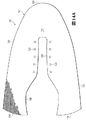
図5および図6では、ニット構成要素130は履物100の残りの部分とは別に図示されている。ニット構成要素130は一体ニット構造から形成されている。本明細書で利用するように、ニット構成要素(例、ニット構成要素130)は、編みプロセスでワンピース要素として形成されると、「一体ニット構造」から形成されていると定義される。すなわち、編みプロセスは、大幅な追加の製造工程またはプロセスの必要なく、ニット構成要素130のさまざまな特徴および構造を実質的に形成する。ニット構成要素130の部分は編みプロセス後に互いに接合してもよいが(例、ニット構成要素130の縁部を互いに接合する)、ニット構成要素130はワンピースニット要素として形成されているため、依然として一体ニット構造から形成されたままである。また、ニット構成要素130は、編みプロセス後に他の要素(例、締めひも122、ベロ124、ロゴ、商標、注意書きおよび材料情報を記載した札)を追加しても、依然として一体ニット構造から形成されたままである。
Knit Component Configuration In FIGS. 5 and 6, the
ニット構成要素130の主要な要素はニット構成131およびインレイストランド132である。ニット要素131は、さまざまなコースおよびウェールを画成する複数の互いにかみ合うループを形成するように操作される(例、編み機を用いて)少なくとも1本のヤーンから形成されている。すなわち、ニット要素131はニット布地の構造を有する。インレイストランド132はニット要素131を通って延びており、ニット要素131内のさまざまなループの間を通っている。インレイストランド132は一般にニット要素131内のコースに沿って延びているが、インレイストランド132はニット要素131のウェールに沿って延びていてもよい。インレイストランド132の利点は、支持、安定性および構造を提供することが含まれる。例えば、インレイストランド132はアッパー120を足の周りに固定するのを助け、アッパー120の区域での変形を制限し(例、耐伸張性を付与する)、締めひも122と連動して履物100のフィット性を高める。
The main elements of the
ニット要素131は、周縁部133、1対のかかと縁部134および内側縁部135により輪郭が描かれる略U字形の構成を有する。履物100に組み込まれるとき、周縁部133はミッドソール111の上面に載せて、ストローベル式中敷き125に接合される。かかと縁部134は互いに接合されており、かかと領域103に垂直に延びている。履物100のいくつかの構成では、材料要素はかかと縁部134間の縫い目を覆って、縫い目を補強するとともに、履物100の美観的な魅力を高めてもよい。内側縁部135は足首開口部121を形成して、締めひも122、開口123およびベロ124が配置される区域まで前方に延びている。くわえて、ニット要素131は第1面136と対向する第2面137とを有する。第1面136はアッパー120の外面の一部を形成するのに対し、第2面137はアッパー120の内面の一部を形成するので、アッパー120内に空洞の少なくとも一部を画成する。
The
前述したように、インレイストランド132はニット要素131を通って延びており、ニット要素131内のさまざまなループの間を通過している。より具体的には、インレイストランド132はニット要素131のニット構造内に配置されており、これは図7A〜図7Dに図示するように、インレイストランド132の区域で、面136および面137との間に単一の布地層の構成を有していてもよい。そのため、ニット構成要素130が履物100に組み込まれるとき、インレイストランド132はアッパー120の外面と内面との間に配置される。いくつかの構成では、インレイストランド132の部分は可視でき、または面136および137の一方もしくは両方に露出していてもよい。例えば、インレイストランド132は面136および137の一方に載せてもよく、またはニット要素131はインレイストランドが通過する凹みもしくは開口を形成していてもよい。インレイストランド132を面136と面137との間に配置させる利点は、ニット要素131がインレイストランド132の擦過およびスナッギングを保護することである。
As described above, the
図5および図6を参照すると、インレイストランド132は周縁部133から内側縁部135に向かって、1つの開口123の側部に隣接して、開口123の少なくとも一部を周って、反対側まで、さらに周縁部133に戻るように繰り返し延びている。ニット構成要素130が履物100に組み込まれるとき、ニット要素131はアッパー120のスロート区域(つまり、締めひも122、開口123およびベロ124が配置されている場所)から、アッパー120の下側区域(つまり、ニット要素131がソール構造110と合わさる場所)まで延びている。この構成では、インレイストランド132もスロート区域から下側区域まで延びている。より具体的には、インレイストランドはスロート区域から下側区域までニット要素131を繰り返し通過している。
Referring to FIGS. 5 and 6, the
ニット要素131はさまざまな方法で形成してもよいが、ニット構造のコースはインレイストランド132と略同じ方向に延びている。すなわち、コースはスロート区域と下側区域との間に延びる方向に延びていてもよい。このように、インレイストランド132の大部分はニット要素131内のコースに沿って延びている。しかし、開口123に隣接する区域では、インレイストランド132はニット要素131内のウェールに沿って延びていてもよい。より具体的には、内側縁部135に平行なインレイストランド132の区間はウェールに沿って延びていてもよい。
The
前述したように、インレイストランド132はニット要素131を繰り返し通過している。図5および図6を参照すると、インレイストランド132は周縁部133でもニット要素131を出てから、周縁部133の別の場所でニット要素131に再進入することを繰り返しており、それによって周縁部133に沿ってループを形成している。この構成の利点は、スロート区域と下側区域との間に延びているインレイストランド132の各区間を、履物100の製造プロセス中に独立して緊張、弛緩またはその他調整してもよいことである。すなわち、ソール構造110をアッパー120に固定する前に、インレイストランド132の区間を適切な張力になるように独立して調整してもよい。
As described above, the
ニット要素131と比べて、インレイストランド132はより大きな耐伸張性を呈してもよい。すなわち、インレイストランド132はニット要素131よりも伸張しなくてもよい。インレイストランド132の多数の区間がアッパー120のスロート区域からアッパー120の下側区域まで延びていることを考えると、インレイストランド132はスロート区域と下側区域との間のアッパー120の部分に耐伸張性を付与する。また、締めひも122に張力を加えることでインレイストランド132に張力を付与し、それによりスロート区域と下側区域との間のアッパー120の部分を足に当てるように誘導してもよい。このように、インレイストランド132は締めひも122と連動して、履物100のフィット性を高める。
Compared to the
ニット要素131は、アッパー120の個別区域に異なる特性を付与するさまざまな種類のヤーンと組み込んでもよい。すなわち、ニット要素131のある区域を、第1特性セットを付与する第1種のヤーンから形成してもよく、ニット要素131の別の区域を、第2特性セットを付与する第2種のヤーンから形成してもよい。この構成では、ニット要素131の異なる区域に特定のヤーンを選択することにより、アッパー120全体で特性を変えてもよい。特定の種類のヤーンがニット要素131の一区域に付与することになる特性は、ヤーン内のさまざまなフィラメントおよびファイバを形成している材料に部分的に依存する。例えば、綿は柔らかな手触り、自然な美観、および生物分解性を提供する。エラステインおよび伸縮性ポリエステルは、それぞれ実質的な伸縮性および復元力を提供し、伸縮性ポリエステルはリサイクル可能性も提供する。レーヨンは光沢に優れ、吸湿性を提供する。ウールも断熱性および生物分解性に加えて、高い吸湿性を提供する。ナイロンは耐久性があり耐擦過性材料で、比較的強度が高い。ポリエステルは疎水性の材料で、比較的高い耐久性も提供する。材料に加えて、ニット要素131のために選択される他の側面がアッパー120の特性に影響することもある。例えば、ニット要素131を形成するヤーンは単繊維または多繊維ヤーンであってもよい。ヤーンはそれぞれ異なる材料から形成される個別のフィラメントを含んでいてもよい。くわえて、ヤーンは、鞘芯構成を有するフィラメントまたは異なる材料から形成される2種類のフィラメントを用いた複合ヤーンなど、それぞれ2以上の異なる材料から形成される個別のフィラメントを含んでいてもよい。撚りおよび捲縮の程度を異ならせること、ならびにデニールを異ならせることでもアッパー120の特性に影響を与えてもよい。したがって、ヤーンを形成する材料およびヤーンの他の側面の両方を、アッパー120の個別区域にさまざまな特性を付与するために選択してもよい。
The
ニット要素131を形成するヤーンと同様、インレイストランド132も大幅に変化させてもよい。ヤーンに加えて、インレイストランド132は、例えば、フィラメント(例、単繊維)、スレッド、ロープ、帯、ケーブル、または鎖の構成を有していてもよい。ニット要素131を形成するヤーンと比べて、インレイストランド132の厚みは厚くてもよい。いくつかの構成では、インレイストランド132はニット要素131のヤーンよりも大幅に厚い厚みを有してもよい。インレイストランド132の断面形状は丸形でもよいが、三角形、正方形、長方形、楕円形または不規則な形状を利用してもよい。また、インレイストランド132を形成する材料は、綿、エラステイン、ポリエステル、レーヨン、ウールおよびナイロンなど、ニット要素131内のヤーンの材料のいずれを含んでいてもよい。前述したように、インレイストランド132はニット要素131よりも大きい耐伸縮性を示してもよい。このように、インレイストランド132に適した材料は、ガラス、アラミド(例、パラアラミドおよびメタアラミド)、超高分子量ポリエチレン、ならびに液晶ポリマーを含め、高引張り強さの用途で利用されるさまざまな工学的フィラメントを含んでいてもよい。別の例として、インレイストランド132としてポリエステル製組糸を利用してもよい。
As with the yarn forming the
ニット構成要素130の一部に適した構成の実施例を図8Aに図示している。この構成では、ニット要素131は複数の水平コースおよび垂直ウェールを画定する複数の互いにかみ合うループを形成するヤーン138を含んでいる。インレイストランド132はコースの1つに沿って延びており、(a)ヤーン138から形成されるループの背後と(b)ヤーン138から形成されるループの前とに交互に配置されている。実際には、インレイストランド132はニット要素131によって形成される構造を縫うように通っている。この構成ではヤーン138はコースのそれぞれを形成するが、追加のヤーンがコースの1以上を形成してもよく、またはコースの1以上の一部を形成してもよい。
An example of a configuration suitable for a portion of the
ニット構成要素130の一部に適した構成の別の実施例を図8Bに図示している。この構成では、ニット要素131はヤーン138と別のヤーン139とを含んでいる。ヤーン138および139は添え糸編みされて、複数の水平コースおよび垂直ウェールを画定する複数の互いにかみ合うループを共同で形成している。すなわち、ヤーン138および139は互いに平行に走行している。図8Aの構成と同様に、インレイストランド132はコースのうちの1つに沿って延びており、(a)ヤーン138および139から形成されるループの背後と、(b)ヤーン138および139から形成されるループの前との間に交互に配置されている。この構成の利点は、ヤーン138および139のそれぞれの特性がニット構成要素130のこの区域に存在してもよいことである。例えば、ヤーン138の色が主にニット要素131のさまざまな編み目の表面に現れ、ヤーン139の色が主にニット要素131のさまざまな編み目の裏面に現れるとすれば、ヤーン138および139は異なる色を有していてもよい。別の実施例として、ヤーン138が主に第1面136に現れ、ヤーン139が主に第2面137に現れるとすれば、ヤーン139はヤーン138よりも柔らかく、足に対してより快適なヤーンから形成してもよい。
Another embodiment of a configuration suitable for a portion of the
図8Bの構成に続くと、ヤーン138は熱硬化性ポリマーおよび天然繊維(例、綿、ウール、絹)のうちの少なくとも1つから形成してもよく、一方ヤーン139は熱可塑性ポリマー材料から形成してもよい。一般に、熱可塑性ポリマー材料は加熱すると溶け、冷却すると固体状態に戻る。より具体的には、熱可塑性ポリマー材料は十分な熱を受けると固体状態から軟化した状態または液体状態に遷移し、さらに熱可塑性ポリマー材料は十分に冷却すると軟化した状態または液体状態から固体状態に遷移する。このように、熱可塑性ポリマー材料は2つの物体または要素を接合するためにしばしば使用される。この場合、ヤーン139は、例えば、(a)ヤーン138のある部分をヤーン138の別の部分に、(b)ヤーン138とインレイストランド132とを互いに、または(c)別の要素(例、ロゴ、商標、ならびに注意書きおよび材料情報を記載した札)をニット構成要素130に接合するために利用してもよい。このように、ヤーン139は、ニット構成要素130の部分を互いに融着またはその他接合するために使用してもよいのであれば、融着性ヤーンと考えてもよい。また、ヤーン138は、一般にニット構成要素130の部分を互いに融着またはその他接合できる材料から形成されていないのであれば、非融着性ヤーンと考えてもよい。すなわち、ヤーン138は非融着性ヤーンとしてもよく、一方ヤーン139は融着性ヤーンとしてもよい。ニット構成要素130のいくつかの構成では、ヤーン138(つまり、非融着性ヤーン)は実質的に熱硬化性ポリエステル材料から形成してもよく、ヤーン139(つまり、融着性ヤーン)は少なくとも部分的に熱可塑性ポリエステル材料から形成してもよい。
Following the configuration of FIG. 8B, the
添え糸編みしたヤーンの使用はニット構成要素130に利点を付与することがある。ヤーン139を加熱して、ヤーン138およびインレイストランド132に融着する場合、このプロセスはニット構成要素130の構造を剛くまたは堅くする効果を有することがある。また、(a)ヤーン138のある部分をヤーン138の別の部分に、または(b)ヤーン138とインレイストランド132を互いに接合すると、ヤーン138およびインレイストランド132の相対的な位置を固定またはロックする効果を有し、それにより耐伸張性および剛性を付与する。すなわち、ヤーン138の部分はヤーン139と融着しても互いに対して滑らず、それによりニット構造の相対的な動きによるニット要素131のねじれまたは永久的な伸びを防止する。別の利点は、ニット構成要素130の一部が傷んできた、またはヤーン138の1つが切れる場合にほつれを制限することに関わる。また、インレイストランド132はニット要素131に対して滑ることがなく、それによりインレイストランド132の部分がニット要素131から外側に引っ張られるのを防止する。したがって、ニット構成要素130の区域は、ニット要素131内に融着性ヤーンおよび非融着性ヤーンを両方使用することで利益が生まれるであろう。
The use of spliced yarns may provide benefits to the knitted
ニット構成要素130の別の側面は、足首開口部121に隣接し、足首開口部121の周りに少なくとも部分的に延びているパッド入り区域に関わる。図7Eを参照すると、パッド入り区域は、一体ニット構造から形成してもよい、重複して少なくとも部分的に同一の広がりをもつ2つのニット層140と、ニット層140間に延びている複数のフローティングヤーン141によって形成されている。ニット層140の側部および縁部は互いに固定されているが、中央区域は一般に固定されていない。このように、ニット層140はチューブまたは筒状構造を効果的に形成し、フローティングヤーン141は筒状構造を貫通するようにニット層140間に配置され、または挿入されてもよい。すなわち、フローティングヤーン141はニット層140間に延びており、ニット層140の表面に略平行で、さらにニット層140間を貫通してその内部空間を埋める。ニット要素131の大部分は機械操作されるヤーンから形成して、互いにかみ合うループを形成するが、フローティングヤーン141は一般にニット層140間の内部空間内で自由であり、またはその他挿入されている。追加事項として、ニット層140は少なくとも部分的にストレッチヤーンから形成してもよい。この構成の利点は、ニット層がフローティングヤーン141を効果的に圧縮し、足首開口部121に隣接するパッド入り区域に弾性性質を提供することである。すなわち、ニット層140内のストレッチヤーンはニット構成要素130を形成する編みプロセス中に緊張状態で配置され、それによりニット層140を、フローティングヤーン141を圧縮するように誘導してもよい。ストレッチヤーンの伸縮性の程度は大幅に変えてもよいが、ニット構成要素130の多くの構成においてストレッチヤーンは少なくとも百パーセント伸縮してもよい。
Another side of the knitted
フローティングヤーン141の存在は足首開口部121に隣接するパッド入り区域に圧縮可能な性質を付与し、それにより履物100の足首開口部121の区域の快適性を高める。多くの従来の履物製品はポリマー発泡体要素または他の圧縮可能な材料を足首開口部に隣接する区域に組み込んでいる。従来の履物製品に対し、一体ニット構造から形成するニット構成要素130の部分はニット構成要素130の残りの部分とともに、足首開口部121に隣接するパッド入り区域を形成してもよい。履物100のさらなる構成において、ニット構成要素130の他の区域に同様なパッド入り区域を配置してもよい。例えば、関節にパッドを付与するために、中足骨と近位指骨との間の関節に対応する区域として同様なパッド入り区域を配置してもよい。あるいは、アッパー120の区域にある程度のパッドを付与するために、テリーループ構造を利用してもよい。
The presence of the floating
上記の説明に基づき、ニット構成要素130はアッパー120にさまざまな特徴を付与する。また、ニット構成要素130はいくつかの従来のアッパー構成より優れたさまざまな利点を提供する。前述したように、従来の履物のアッパーは、例えば縫製または接着により接合される複数の材料要素(例、布地、ポリマー発泡体、ポリマーシート、革、合成皮革)から形成されている。アッパーに組み込まれる材料要素の数および種類が増えるほど、材料要素を輸送、保管、切断および接合することに関連する時間および費用も増大するであろう。切断および縫製プロセスから出る廃材も、アッパーに組み込まれる材料要素の数および種類が増えるほど、より多く蓄積する。また、材料要素の数が多いアッパーは、種類および数が少ない材料要素から形成されているアッパーよりもリサイクルが難しくなるであろう。そのため、アッパーに利用される材料要素の数を減らすことにより、アッパーの製造効率およびリサイクル性を高めながら廃棄物が減少するであろう。このために、ニット構成要素130は、製造効率を高め、廃棄物を減少し、リサイクル性を簡単にしながら、アッパー120の実質的な部分を形成する。
Based on the above description, the
さらなるニット構成要素の構成
ニット構成要素150が図9および図10に図示されており、履物100のニット構成要素130の代わりに利用してもよい。ニット構成要素150の主要な要素は、ニット要素151およびインレイストランド152である。ニット要素151は操作される(例、編み機を用いて)少なくとも1本のヤーンから形成され、さまざまなコースおよびウェールを画定する複数の互いにかみ合うループを形成する。すなわち、ニット要素151はニット布地の構造を有する。インレイストランド152はニット要素151を通って延びており、ニット要素151内のさまざまなループの間を通過している。インレイストランド152は大略的にニット要素151内のコースに沿って延びているが、インレイストランド152はニット要素151内のウェールに沿って延びていてもよい。インレイストランド132と同様、インレイストランド152は耐伸張性を付与し、履物100に組み込まれると、締めひも122と連動して履物100のフィット性を高める。
Additional Knit Component Configuration
ニット要素151は、周縁部153、1対のかかと縁部154および内側縁部155によって輪郭が描かれる略U字形の構成を有する。くわえて、ニット要素151は第1面156および対向する第2面157を有する。第1面156はアッパー120の外面の一部を形成してもよく、一方、第2面157はアッパー120の内面の一部を形成してもよいため、アッパー120内に空洞の少なくとも一部を画定する。多くの構成では、ニット要素151はインレイストランド152の区域で単一の布地層の構成を有していてもよい。すなわち、ニット要素151は面156と面157との間の単一の布地層であってもよい。くわえて、ニット要素151は複数の開口158を画定する。
The
インレイストランド132と同様に、インレイストランド152は周縁部153から内側縁部155に向かって、少なくとも部分的に開口158の1つを周って、さらに周縁部153に戻るように繰り返し延びている。しかし、インレイストランド132と対照的に、インレイストランド152のある部分は後方に角度をつけて曲がり、かかと縁部154まで延びている。より具体的には、最後方の開口158に関連するインレイストランド152の部分は、かかと縁部154の1つから内側縁部155に向かって、少なくとも部分的に最後方の開口158を周って、さらにかかと縁部154の1つに戻るように延びている。さらに、インレイストランド152のいくつかの部分は開口158の1つの周りに延びていない。さらに具体的には、インレイストランド152のいくつかの区画は内側縁部155に向かって延びており、開口158の1つに隣接する区域で方向転換して、周縁部153またはかかと縁部154の1つに向かって戻るように延びている。
Similar to the
ニット要素151はさまざまな方法で形成してもよいが、ニット構造のコースは大略的にインレイストランド152と同じ方向に延びている。しかし、開口158に隣接する区域では、インレイストランド152はニット要素151内のウェールに沿って延びていてもよい。より具体的には、内側縁部155に平行なインレイストランド152の区画はウェールに沿って延びていてもよい。
Although the
ニット要素151と比べ、インレイストランド152はより大きな耐伸張性を示してもよい。すなわち、インレイストランド152はニット要素151よりも伸張しなくてもよい。インレイストランド152の多数の区画がニット要素151を通って延びているのであれば、インレイストランド152はスロート区域と下側区域との間のアッパー120の部分に耐伸張性を付与してもよい。また、締めひも122に張力をかけることでインレイストランド152に張力を付与し、それによってスロート区域と下側区域との間のアッパー120の部分を足に当てるように誘導してもよい。さらに、インレイストランド152の多数の区画がかかと縁部154に向かって延びているのであれば、インレイストランド152はアッパー120のかかと領域103の部分に耐伸張性を付与してもよい。また、締めひも122に張力をかけることで、かかと領域103のアッパー120の部分が足に当たるように誘導してもよい。このように、インレイストランド152は締めひも122と連動して、履物100のフィット性を高める。
Compared to the
ニット要素151は、ニット要素131について上記説明したさまざまな種類のヤーンのいずれを組み込んでもよい。インレイストランド152も、インレイストランド132について上記説明した構成および材料のいずれから形成してもよい。さらに、図8Aおよび図8Bに関して説明したさまざまなニット構成も、ニット構成要素150で利用してもよい。より具体的には、ニット要素151は単一のヤーン、2種類を添え糸編みしたヤーン、または融着性ヤーンおよび非融着性ヤーンから形成される区域を有していてもよく、融着性ヤーンが、(a)非融着性ヤーンのある部分を非融着性ヤーンの別の部分に、または(b)非融着性ヤーンとインレイストランド152を互いに接合する。
The
ニット要素131の大部分は、比較的テクスチャード加工していない布地、共通または単一ニット構造(例、筒状ニット構造)から形成されているように図示されている。対して、ニット要素151はニット構成要素150の異なる区域に特定の特性および利点を付与するさまざまなニット構造を組み込んでいる。また、さまざまなヤーンの種類をニット構造と組み合わせることにより、ニット構成要素150はアッパー120の異なる区域に幅広い特性を付与してもよい。図11を参照すると、ニット構成要素150の模式図は異なるニット構造を有するさまざまなゾーン160〜169を示しており、そのそれぞれをここで詳細に説明していく。参照のために、図11では、領域101〜103および側部104および105のそれぞれは、ニット構成要素150が履物100に組み込まれたときに、ニットゾーン160〜169の位置の参照となるように示している。
Most of the
筒状ニットゾーン160は、周縁部153の大部分に沿って、側部104および105の両方の領域101〜103のそれぞれを通って延びている。筒状ニットゾーン160は、境界領域101および102にほぼ配置されている区域で側部104および105のそれぞれから内側にも延びて、内側縁部155の前方部分を形成している。筒状ニットゾーン160は比較的テクスチャード加工していないニット構成を形成している。図12Aを参照すると、筒状ニットゾーン160の区域を通る断面が図示されており、面156および157は互いに実質的に平行である。筒状ニットゾーン160は履物100にさまざまな利点を付与する。例えば、筒状ニットゾーン160は、特に筒状ニットゾーン160のヤーンを融着性ヤーンで添え糸編みすると、他のいくつかのニット構造よりも耐久性および耐摩耗性がある。さらに、筒状ニットゾーン160の比較的テクスチャード加工していない性質はストローベル式中敷き125を周縁部153に接合するプロセスを簡単にする。すなわち、周縁部153に沿って配置されている筒状ニットゾーン160の部分は、履物100のラスティングプロセスを容易にする。参照のために、図13Aは筒状ニットゾーン160を編みプロセスで形成する態様のループ図を図示している。
The cylindrical knitted
2つのストレッチニットゾーン161が周縁部153から延びており、足の中足骨と近位指骨との間の関節の位置に対応するように配置されている。すなわち、ストレッチゾーンは、境界領域101および102にほぼ配置されている区域で周縁部から内側に延びている。筒状ニットゾーン160と同様に、ストレッチニットゾーン161のニット構成は筒状ニット構造にしてもよい。しかし、筒状ニットゾーン160と対照的に、ストレッチニットゾーン161はニット構成要素150に伸縮性および復元性を付与するストレッチヤーンから形成されている。ストレッチヤーンの伸縮性の程度は大幅に変わってもよいが、ニット構成要素150の多くの構成においてストレッチヤーンは少なくとも百パーセント伸縮してもよい。
Two
筒状の両面タックニットゾーン162が、少なくとも中足領域102の内側縁部155の部分に沿って延びている。筒状の両面タックニットゾーン162も比較的テクスチャード加工していないニット構成を形成してもよいが、筒状ニットゾーン160よりも厚い厚みを有する。断面では、筒状の両面タックニットゾーン162は図12Aと類似しており、面156および157は互いに実質的に平行である。筒状の両面タックニットゾーン162は履物100にさまざまな利点を付与する。例えば、筒状の両面タックニットゾーン162は他のいくつかのニット構造よりも耐伸張性があり、締めひも122が筒状の両面タックニットゾーン162およびインレイストランド152に張力をかけるとき有利である。参照のために、図13Bは、筒状の両面タックニットゾーン162を編みプロセスで形成する態様のループ図を図示している。
A cylindrical double-sided
1×1メッシュのニットゾーン163が足先領域101に配置されて、周縁部153から内側に離れている。1×1メッシュのニットゾーンは、図12Bに図示するように、C字形の構成を有し、ニット要素151を通って、第1面156から第2面157まで延びている複数の開口を形成している。開口はニット構成要素150の通気性を高め、空気をアッパー120に進入させ、水分をアッパー120から逃がすことができる。参照のために、図13Cは、1×1メッシュのニットゾーン163を編みプロセスで形成する態様のループ図を図示している。
A 1 × 1
2×2メッシュのニットゾーン164が1×1メッシュのニットゾーン163に隣接して延びている。1×1メッシュのニットゾーン163と比べて、2×2メッシュのニットゾーン164はより大きな開口を形成し、ニット構成要素150の通気性をさらに高めるであろう。参照のために、図13Dは、2×2メッシュのニットゾーン164を編みプロセスで形成する態様のループ図を図示している。
A 2 × 2
3×2メッシュのニットゾーン165が2×2メッシュのニットゾーン164内に配置されており、別の3×2メッシュのニットゾーン165がストレッチゾーン161の1つに隣接して配置されている。1×1メッシュのニットゾーン163および2×2メッシュのニットゾーン164と比べて、3×2メッシュのニットゾーン165はさらに大きな開口を形成し、ニット構成要素150の通気性をさらに高めるであろう。参照のために、図13Eは、3×2メッシュのニットゾーン165を編みプロセスで形成する態様のループ図を図示している。
A 3 × 2
1×1モックメッシュのニットゾーン166が足先領域101に配置されており、1×1メッシュのニットゾーン163の周りに延びている。ニット要素151を通る開口を形成するメッシュのニットゾーン163〜165と対照的に、図12Cに図示するように、1×1モックメッシュのニットゾーン166は第1面156に凹みを形成する。履物100の美観を向上させることに加えて、1×1モックメッシュのニットゾーン166はニット構成要素150の柔軟性を高めるとともに、全体の質量を減少させる。参照のために、図13Fは、1×1モックメッシュのニットゾーン166を編みプロセスで形成する態様のループ図を図示している。
A 1 × 1 mock
2つの2×2モックメッシュのニットゾーン167がかかと領域に、かかと縁部154に隣接して配置されている。1×1モックメッシュのニットゾーン166と比べて、2×2モックメッシュのニットゾーン167は第1面156により大きな凹みを形成する。図12Dに図示するように、インレイストランド152が2×2モックメッシュのニットゾーン167の凹みを通って延びている区域では、インレイストランド152は見えて、凹みの下側区域に露出されるであろう。参照のために、図13Gは、2×2モックメッシュのニットゾーン167を編みプロセスで形成する態様のループ図を図示している。
Two 2 × 2 mock
2つの2×2ハイブリッドニットゾーン168が中足領域102に、2×2モックメッシュのニットゾーン167の前方に配置されている。2×2ハイブリッドニットゾーン168は2×2メッシュのニットゾーン164および2×2モックメッシュのニットゾーン167の特徴を共有する。より具体的には、2×2ハイブリッドニットゾーン168は2×2メッシュのニットゾーン164のサイズおよび構成を有する開口を形成するとともに、2×2ハイブリッドニットゾーン168は2×2モックメッシュのニットゾーン167のサイズおよび構成を有する凹みを形成する。図12Eに図示するように、インレイストランド152が2×2ハイブリッドニットゾーン168の凹みを通って延びている区域では、インレイストランド152は見えて露出している。参照のために、図13Hは、2×2ハイブリッドニットゾーン168を編みプロセスで形成する態様のループ図を図示している。
Two 2 × 2
ニット構成要素150は、ニット構成要素130について上記説明した足首開口部121に隣接して、少なくとも部分的に足首開口部121の周りに延びているパッド入り区域の一般構成を有する2つのパッド入りゾーン169を含んでいてもよい。このように、パッド入りゾーン169は、重複して少なくとも部分的に同一の広がりをもつ一体ニット構造から形成してもよい2つのニット層と、ニット層の間に延びている複数のフローティングヤーンとによって形成されている。
The
図9および図10との比較から、ニット要素151のテクスチャリングの大部分は、第2面157ではなく、第1面156に配置されていることが明らかになる。すなわち、モックメッシュのニットゾーン166および167により形成される凹み、ならびに2×2ハイブリッドニットゾーン168の凹みは、第1面156に形成される。この構成は履物100の快適性を高めるという利点を有する。より具体的には、この構成は第2面157の比較的テクスチャード加工していない構成を足に当てる。図9と図10とのさらなる比較から、インレイストランド152の部分は第1面156で露出しているが、第2面157では露出していないことが明らかになる。この構成も履物100の快適性を高めるという利点を有する。さらに具体的には、インレイストランド152をニット要素151の一部により足から離すことにより、インレイストランド152が足に接触することはない。
Comparison with FIGS. 9 and 10 reveals that most of the texturing of the
ニット構成要素130の追加構成を図14A〜図14Cに図示している。ニット構成要素130に関係して説明するが、これらの構成のそれぞれに関連する概念はニット構成要素150にも利用してもよい。図14Aを参照すると、インレイストランド132はニット構成要素130にはない。インレイストランド132はニット構成要素130の区域に耐伸張性を付与するが、いくつかの構成ではインレイストランド132からの耐伸張性を必要としなくてもよい。また、いくつかの構成はアッパー120の伸縮性が大きいことから利益を得ることがある。図14Bを参照すると、ニット要素131はニット要素131の残りの部分と合わせて一体ニット構造から形成されて、周縁部133でニット構成要素130の長さに沿って延びている2つのフラップを含んでいる。履物100に組み込む場合、フラップ142がストローベル式中敷き125に置き換わってもよい。すなわち、フラップ142は、中敷き113の下に延びて、ミッドソール111の上面に固定されているアッパー120の一部を共同で形成してもよい。図14Cを参照すると、ニット構成要素130は中足領域102に制限されている構成を有する。この構成では、他の材料要素(例、布地、ポリマー発泡体、ポリマーシート、革、合成皮革)を、例えば縫製または接着によりニット構成要素130に接合して、アッパー120を形成してもよい。
Additional configurations of the
上記の説明に基づき、ニット構成要素130および150のそれぞれは、アッパー120に特徴および利点を付与するさまざまな構成を有していてもよい。より具体的には、ニット要素131および151はアッパー120の異なる区域に特定の特性を付与するさまざまなニット構造およびヤーンの種類を組み込んでもよく、インレイストランド132および152はアッパー120の区域に耐伸張性を付与し、締めひも122と連動して履物100のフィット性を高めるように、ニット構造を通って延びていてもよい。
Based on the above description, each of the knit
編み機およびフィーダーの構成
編みは手で行ってもよいが、ニット構成要素の商業的な製造は一般に編み機で行われる。ニット構成要素130および150のいずれの生産にも適した編み機200の一実施例を図15に図示している。編み機200は例示のためにVベッド型横編み機の構成を有しているが、ニット構成要素130および150またはニット構成要素130および150の側面のいずれも他の種類の編み機で生産してもよい。
Knitting Machine and Feeder Configuration While knitting may be done by hand, the commercial production of knitted components is generally done on a knitting machine. One embodiment of a
編み機200は互いに対して角度を成すことによりVベッドを形成している2つの針床201を含んでいる。針床201のそれぞれは共通平面上にある複数の個々の針202を含んでいる。すなわち、一方の針床201からの針202は第1平面にあり、他方の針床201からの針202は第2平面にある。第1平面および第2平面(つまり、2つの針床201)は互いに対して角度を成しており、相交わって編み機200の幅の大部分に沿って延びている交差部を形成する。以下さらに詳細に説明するように、針202はそれぞれ後退する第1位置と、延伸する第2位置とを有する。第1位置では、針202は第1平面と第2平面とが相交わる交差部から離れている。しかし、第2位置では、針202は第1平面と第2平面とが相交わる交差部を通過する。
The
1対のレール203が針床201の交差部の上にかつ平行に延びており、複数の標準フィーダー204およびコンビネーションフィーダー220の装着ポイントを提供する。各レール203は2つの側部を有し、そのそれぞれが1つの標準フィーダー204または1つのコンビネーションフィーダー220のいずれかを収容する。このように、編み機200は合計で4つのフィーダー204および220を含んでもよい。図示するように、最前列のレール203は対向する側部に1つのコンビネーションフィーダー220および1つの標準フィーダー204を含み、最後列のレール203は対向する側部に2つの標準フィーダー204を含んでいる。2本のレール203を図示しているが、編み機200のさらなる構成は追加のレール203を組み込んで、より多くのフィーダー204および220の装着ポイントを提供してもよい。
A pair of
キャリッジ205の作用により、フィーダー204および220はレール203および針床201に沿って移動し、それによって針202にヤーンを供給する。図15では、ヤーン206はスプール207によってコンビネーションフィーダー220に供給されている。より具体的には、ヤーン206はスプール207からさまざまなヤーンガイド208、ヤーン引きばね209およびヤーンテンショナー210に延びてから、コンビネーションフィーダー220に進入する。図示していないが、ヤーンをフィーダー204に供給するために、追加スプール207を利用してもよい。
By the action of the
標準フィーダー204は、編み機200などのVベッド型横編み機で従来から利用されている。すなわち、既存の編み機は標準フィーダー204を組み込んでいる。各標準フィーダー204は、針202によって編み、タック編みおよび浮き編みされるヤーンを供給する能力を有する。比較として、コンビネーションフィーダー220は、針202によって編み、タック編みおよび浮き編みされるヤーン(例、ヤーン206)を供給する能力を有すると共に、ヤーンを挿入する能力を有する。また、コンビネーションフィーダー220はさまざまな異なるステップ(例、フィラメント、スレッド、ロープ、帯、ケーブル、鎖またはヤーン)を挿入する能力を有する。したがって、コンビネーションフィーダー220は各標準フィーダー204よりも優れた汎用性を示す。
The
前述したように、コンビネーションフィーダー220は、ヤーンを編み、タック編みおよび浮き編みすることに加えて、ヤーンまたは他のストランドを挿入するときに利用してもよい。コンビネーションフィーダー220を組み込んでいない従来の編み機もヤーンを挿入してもよい。より具体的には、インレイフィーダーが供給されている従来の編み機もヤーンを挿入してもよい。Vベッド型横編み機の従来のインレイフィーダーは、ヤーンを挿入するために連動する2つの構成要素を含んでいる。インレイフィーダーの構成要素のそれぞれが、2つの隣接するレール上の個別の装着ポイントに固定されており、それによって2つの装着ポイントを占めている。個々の標準フィーダー204は1つの装着ポイントしか占めないが、インレイフィーダーを利用してヤーンをニット構成要素に挿入するときには一般に2つの装着ポイントが占められる。また、コンビネーションフィーダー220は1つの装着ポイントしか占めないが、従来のインレイフィーダーは2つの装着ポイントを占める。
As previously mentioned, the
編み機200が2本のレール203を含んでいるのであれば、編み機200には4つの装着ポイントが利用できる。従来のインレイフィーダーを編み機200に利用した場合、標準フィーダー204には2つの装着ポイントしか利用できないであろう。しかし、編み機200にコンビネーションフィーダー220を使用すると、標準フィーダー204に3つの装着ポイントが利用できる。したがって、ヤーンまたは他のストランドを挿入するときにコンビネーションフィーダー220を利用してもよく、コンビネーションフィーダー220は1つの装着ポイントしか占めないという利点を有する。
If the
キャリア230、フィーダーアーム240および1対の作動部材250を含むコンビネーションフィーダー220を図16〜図19に個別に図示している。コンビネーションフィーダー220の大半は金属材料(例、スチール、アルミニウム、チタン)から形成してもよいが、キャリア230、フィーダーアーム240および作動部材250の部分は、例えば、ポリマー、セラミックまたは複合材料から形成してもよい。前述したように、コンビネーションフィーダー220は、ヤーンを編み、タック編みおよび浮き編みするときに加えて、ヤーンまたは他のストランドを挿入するときに利用してもよい。特に図16を参照すると、ストランドがコンビネーションフィーダー220に界接する態様を例示するために、ヤーン206の一部が図示されている。
A
キャリア230は略方形構成を有しており、4本のボルト233で接合されている第1カバー部材231および第2カバー部材232を含んでいる。カバー部材231および232は、フィーダーアーム240および作動部材250の部分が配置されている内部空洞を画定している。キャリア230はフィーダー220をレール230のうちの1本に固定するために、第1カバー部材231から外側に延びている装着要素234も含んでいる。装着要素234の構成は変わることがあるが、図17に図示するように、装着要素234は鳩尾形状を形成する2つの離間した張出区域を含むように図示されている。レール203のうちの1本の逆鳩尾構成が装着要素234の鳩尾形状まで延びて、コンビネーションフィーダー220を編み機200に効果的に接合してもよい。図18に図示するように、第2カバー部材232は中心に位置して細長いスロット235を形成することにも留意するべきである。
The
フィーダーアーム240は、キャリア230(つまり、カバー部材231と232との間の空洞)を通って、キャリア230の下側から外側に延びている略細長い構成を有する。他の要素に加えて、フィーダーアーム240は作動ボルト241と、ばね242と、プーリ243と、ループ244と、給糸区域245とを含んでいる。作動ボルト241はフィーダーアーム240から外側に延びており、カバー部材231と232との間の空洞内に位置している。図18に図示するように、作動ボルト241の片側は第2カバー部材232のスロット235内にも配置されている。ばね242はキャリア230およびフィーダーアーム240に固定されている、より具体的には、ばね242の一端がキャリア230に固定されており、ばね242の他端がフィーダーアーム240に固定されている。プーリ243、ループ244および給糸区域245がフィーダーアーム240に存在して、ヤーン206または別のストランドと界接する。また、プーリ243、ループ244および給糸区域245は、ヤーン206または別のストランドがコンビネーションフィーダー220をスムーズに通過することを確実にし、それによって針202に確実に供給されるように構成されている。再び図16を参照すると、ヤーン206はプーリ243を周り、ループ244を通って、給糸区域245に延びている。くわえて、ヤーン206は、フィーダーアーム240の末端領域である給糸先端部246から延びて、さらに針202に供給される。
作動部材250のそれぞれはアーム251およびプレート252を含んでいる。作動部材250の多くの構成では、各アーム251はプレート252の1枚とともにワンピース要素として形成されている。アーム251はキャリア230の外側かつキャリア230の上側に配置されているが、プレート252はキャリア230内に配置されている。アーム251のそれぞれは外側端253および反対の内側端254を画成する細長い構成を有し、アーム251は両内側端254の間の空間を画成するように位置付けられている。すなわち、アーム251は互いに離間している。プレート252は略平面構成を有する。図19を参照すると、プレート252のそれぞれは傾斜縁部257を備える開口256を画定する。また、フィーダーアーム240の作動ボルト241が各開口256に延びている。
Each
前述したコンビネーションフィーダー220の構成は、フィーダーアーム240の並進運動を容易にする構造を提供する。以下さらに詳細に述べるように、フィーダーアーム240の並進運動は給糸先端部246を針床201の交差部の上または下の位置に選択的に位置付ける。すなわち、給糸先端部246は針床201の交差部を通って往復運動する能力を有する。フィーダーアーム240の並進運動の利点は、コンビネーションフィーダー220が、(a)給糸先端部246が針床201の交差部の上に位置付けられるとき、編み、タック編みおよび浮き編みをするためにヤーン206を供給する、ならびに(b)給糸先端部246が針床201の交差部の下に位置付けられるとき、挿入するためにヤーン206または別のストランドを供給することである。また、フィーダーアーム240はコンビネーションフィーダー220が利用されている態様によって2つの位置の間を往復運動する。
The configuration of the
針床201の交差部を往復運動する際、フィーダーアーム240は後退位置から延伸位置まで並進する。後退位置にあるとき、給糸先端部246は針床201の交差部の上に位置付けられる。延伸位置にあるとき、給糸先端部246は針床201の交差部の下に位置付けられる。フィーダーアーム240が延伸位置にあるときよりもフィーダーアーム240が後退位置にあるときの方が、給糸先端部246はキャリア230に近い。同様に、フィーダーアーム240が後退位置にあるときよりもフィーダーアーム240が延伸位置にあるときの方が、給糸先端部246はキャリア230から遠い。言い換えると、給糸先端部246は延伸位置ではキャリア230から離れるように移動し、給糸先端部246は後退位置にあるときはキャリア230に近づくように移動する。
When reciprocating the intersection of the
図16〜20Cおよび後で説明するさらなる図面において参照のために、矢印221を給糸区域245に隣接して位置付けている。矢印221が上向きまたはキャリア230に向かう方向を指している場合、フィーダーアーム240は後退位置にある。矢印221が下向きまたはキャリア230から遠ざかる方向を指している場合、フィーダーアーム240は延伸位置にある。したがって、矢印221の位置を参照することにより、フィーダーアーム240の位置は容易に確認されるであろう。
For reference in FIGS. 16-20C and further figures described below,
フィーダーアーム240の自然な状態は後退位置である。すなわち、コンビネーションフィーダー220の区域に一切有意な力を加えなければ、フィーダーアーム240は後退位置にとどまる。例えば、図16〜図19を参照すると、コンビネーションフィーダー220と相互作用する力または他の影響は示されておらず、フィーダーアーム240は後退位置にある。しかし、アーム251の1つに十分な力が加わると、フィーダーアーム240の並進運動が生じる。より具体的には、外側端253の1つに十分な力が加わり、空間255に向けられると、フィーダーアーム240の並進運動が起こる。図20Aおよび図20Bを参照すると、力222は外側端253の1つに作用して空間255に向けられ、フィーダーアーム240が延伸位置に並進したところが示されている。しかし、力222を取り除くと、フィーダーアーム240は後退位置に戻る。図20Cは、内側端254に作用し外側に向いているときの力222を図示しており、フィーダーアーム240は後退位置にとどまっていることにも留意するべきである。
The natural state of the
前述したように、フィーダー204および220は、キャリッジ205の作用のためにレール203および針床201に沿って移動する。より具体的には、キャリッジ205内の駆動ボルトがフィーダー204および220と接触して、フィーダー204および220を針床201に沿って押す。コンビネーションフィーダー220に関して、駆動ボルトは外側端253の1つまたは内側端254の1つのいずれかに接触して、コンビネーションフィーダー220を針床201に沿って押す。駆動ボルトが外側端253の1つに接触すると、フィーダーアーム240は延伸位置に並進して、給糸先端部246が針床201の交差部の下を通る。駆動ボルトが内側端254の1つに接触して空間255内に配置されると、フィーダーアーム240は後退位置にとどまり、給糸先端部246は針床201の交差部の上になる。したがって、キャリッジ205がコンビネーションフィーダー220に接触する区域が、フィーダーアーム240が後退位置にあるか、または延伸位置にあるかを決定する。
As described above, the
ここでコンビネーションフィーダー220の機械的作用を説明する。図19〜図20Bは、第1カバー部材231を取り除いて、キャリア230の空洞内の要素を露出した状態のコンビネーションフィーダー220を図示している。図19と図20Aおよび図20Bを比較することにより、力222がフィーダーアーム240を並進するように誘導する様子が明らかであろう。力222が外側端253の1つに作用すると、作動部材250の1つがフィーダーアーム240の長さに垂直な方向に滑動する。すなわち、作動部材250は図19〜図20Bにおいて水平に滑動する。作動部材250の1つの運動が作動ボルト241を傾斜縁部257の1つに係合させる。作動部材250の運動がフィーダーアーム240の長さに垂直な方向に規制されるのであれば、作動ボルト241は傾斜縁部257に対して回転または滑動し、フィーダーアーム240を延伸位置に並進するように誘導する。力222を取り除くと、ばね242がフィーダーアーム240を延伸位置から後退位置に引く。
Here, the mechanical action of the
上記説明に基づくと、コンビネーションフィーダー220は、ヤーンまたは他のストランドが編み、タック編みもしくは浮き編みのために利用されているか、または挿入のために利用されているかに応じて、後退位置と延伸位置とを往復運動する。コンビネーションフィーダー220は、力222の印加がフィーダーアーム240を後退位置から延伸位置に並進させるように誘導し、力222の排除がフィーダーアーム240を延伸位置から後退位置に並進するように誘導する構成を有する。すなわち、コンビネーションフィーダー220は、力222の印加および排除がフィーダーアーム240を針床201の対向する側部の間を往復運動させる構成を有する。一般に、外側端253は作動区域と考えてもよく、フィーダーアーム240の運動を誘導する。コンビネーションフィーダー220のさらなる構成では、作動区域は他の位置にあってもよく、または他の刺激に応答してフィーダーアーム240の運動を誘導してもよい。例えば、作動区域は、フィーダーアーム240の運動を制御するサーボ機構に連結されている電気入力であってもよい。したがって、コンビネーションフィーダー220は、前述した構成と同じ一般的な態様で動作するさまざまな構造を有していてもよい。
Based on the above description, the
編みプロセス
ここで、編み機200がニット構成要素を製造するために動作する態様を詳しく説明していく。また、以下の説明は編みプロセス中のコンビネーションフィーダー220の動作を実証する。図21Aを参照すると、さまざまな針202と、レール203と、標準フィーダー204と、コンビネーションフィーダー220とを含んでいる編み機200の一部が図示されている。コンビネーションフィーダー220はレール203の前側に固定されているが、標準フィーダー204はレール203の後側に固定されている。ヤーン206はコンビネーションフィーダー220を通過し、ヤーン206の一端が給糸先端部246から外側に延びている。ヤーン206が図示されているが、他のあらゆるストランド(例、フィラメント、スレッド、ロープ、帯、ケーブル、鎖またはヤーン)がコンビネーションフィーダー220を通過してもよい。別のヤーン211が標準フィーダー204を通過してニット構成要素260の一部を形成し、ニット構成要素260の最上コースを形成するヤーン211のループが針202の末端に配置されているフックによって保持されている。
Knitting Process Here, the manner in which the
本明細書で説明する編みプロセスはニット構成要素260の形成に関係するが、これはニット構成要素130および150と同様なニット構成要素を含め、あらゆるニット構成要素であってもよい。説明のために、図面では、ニット構造を例示できるように、ニット構成要素260の比較的小さな区画しか示していない。また、編み機200およびニット構成要素260のさまざまな要素の縮尺または比率は、編みプロセスをよりよく例証するために拡大している。
Although the knitting process described herein involves the formation of
標準フィーダー204は給糸先端部213を備えるフィーダーアーム212を含んでいる。フィーダーアーム212は給糸先端部213を、(a)針202間の中心になる、および(b)針床201の交差部の上になる位置に位置付ける角度を成している。図22Aはこの構成の模式的な断面図を図示している。針202は異なる平面上にあり、互いに対して角度を成していることに留意する。すなわち、針床201からの針202は異なる平面上にある。針202はそれぞれ第1位置および第2位置を有する。実線で示される第1位置では、針202は後退している。点線で示される第2位置では、針202は延伸している。第1位置で、針202は針床201のある平面が相交わる交差部から離れている。しかし、第2位置では、針は延びて、針床201のある平面が相交わる交差部を通過している。すなわち、針202は第2位置に延伸すると互いに交差する。給糸先端部213は平面の交差部の上に配置されていることに留意するべきである。この位置で、給糸先端部213は編み、タック編みおよび浮き編みのためにヤーン211を針202に供給する。
The
コンビネーションフィーダー220は、矢印221の向きで明確に示されるように、後退位置にある。フィーダーアーム240はキャリア230から下側に延びて、給糸先端部246を、(a)針202の間の中心になる、および(b)針床201の交差部の上になる位置に位置付ける。図22Bはこの構成の模式的な断面図を図示している。給糸先端部246は図22Aの給糸先端部213と同じ相対的な位置に位置付けられていることに留意する。
The
ここで図21Bを参照すると、標準フィーダー204はレール203に沿って移動し、ヤーン211からニット構成要素260に新たなコースが形成されている。より具体的には、針202は前のコースのループを通してヤーン211の区画を引き、それによって新たなコースを形成する。したがって、標準フィーダー204を針202に沿って移動し、それによって針202がヤーン211を操作して、ヤーン211から追加のループを形成できるようにすることで、ニット構成要素260にコースを追加してもよい。
Referring now to FIG. 21B, the
編みプロセスを続けると、図21Cに図示するように、フィーダーアーム240は、今度は後退位置から延伸位置に並進する。延伸位置では、フィーダーアーム240はキャリア230から下側に延びて、給糸先端部246を、(a)針202の間の中心になる、および(b)針床201の交差部の下になる位置に位置付ける。図22Cはこの構成の模式的な断面図を図示している。給糸先端部246は、フィーダーアーム240の並進運動のために、図22Bの給糸先端部246の位置の下に位置付けられていることに留意する。
As the knitting process continues, the
ここで図21Dを参照すると、コンビネーションフィーダー220はレール203に沿って移動し、ヤーン206はニット構成要素260のループ間に配置されている。すなわち、ヤーン206はいくつかのループの前かつ他のループの背後に交互パターンで配置されている。また、ヤーン206はある針床201からの針202によって保持されているループの前に配置されるとともに、ヤーン206は他方の針床201からの針202によって保持されているループの背後に配置されている。フィーダーアーム240は、ヤーン206を針床201の交差部の下の区域に置くために、延伸位置にとどまっていることに留意する。こうしてヤーン206を図21Bの標準フィーダー204によって直前に形成されたコース内に効果的に配置する。
Referring now to FIG. 21D, the
ヤーン206をニット構成要素260に完全に挿入するために、図21Eに図示するように、標準フィーダー204はレール203に沿って移動して、ヤーン211から新たなコースを形成する。新たなコースを形成することによって、ヤーン206はニット構成要素260の構造内に効果的に編み込まれ、またはその他の形で統合される。この段階で、フィーダーアーム240も延伸位置から後退位置に並進してもよい。
In order to fully insert the
図21Dおよび図21Eは、レール203に沿ったフィーダー204および220の個別の移動を示している。すなわち、図21Dはレール203に沿ったコンビネーションフィーダー220の第1移動を示し、図21Eはレール203に沿った標準フィーダー204の第2のその後の移動を示している。多くの編みプロセスでは、フィーダー204および220は同時にヤーン206を挿入しながらヤーン211から新たなコースを形成するために効果的に移動してもよい。しかし、ヤーン211から新たなコースを形成する前にヤーン206を位置付けるために、コンビネーションフィーダー220は標準フィーダー204に先立って、または前に移動する。
21D and 21E show the individual movement of
上記説明で概説した一般的な編みプロセスは、インレイストランド132および152をニット要素131および151に配置してもよい態様の実施例を提供する。より具体的には、ニット構成要素130および150は、コンビネーションフィーダー220を利用して、インレイストランド132および152をニット要素131に効果的に挿入することによって形成してもよい。フィーダーアーム240の往復運動を考えると、インレイストランドは新たなコースを形成する前に以前に形成されたコース内に配置してもよい。
The general knitting process outlined in the above description provides an example of how the
編みプロセスを続けると、図21Fに図示するように、フィーダーアーム240は、今度は後退位置から延伸位置に並進する。図21Gに図示するように、次にコンビネーションフィーダー220がレール203に沿って移動して、ヤーン206がニット構成要素260のループ間に配置される。これによりヤーン206は図21Eの標準フィーダー204で形成されたコース内に効果的に配置する。ヤーン206をニット構成要素260に完全に挿入するために、図21Hに図示するように、標準フィーダー204はレール203に沿って移動して、ヤーン211から新たなコースを形成する。新たなコースを形成することにより、ヤーン206はニット構成要素260の構造内に効果的に編み込まれ、またはその他の形で統合される。この段階で、フィーダーアーム240も延伸位置から後退位置に並進してもよい。
As the knitting process continues, the
図21Hを参照すると、ヤーン206は2つのインレイ区画の間にループ214を形成している。上記ニット構成要素130の説明において、インレイストランド132は周縁部133でニット要素131を出てから、周縁部133の別の位置でニット要素131に再進入するのを繰り返し、それによって図5および図6で分かるように、周縁部133に沿ってループを形成することに留意した。ループ214は同様に形成される。すなわち、ループ214はヤーン206がニット構成要素260のニット構造を出てから、ニット構造に再進入するところに形成される。
Referring to FIG. 21H, the
上記説明したように、標準フィーダー204は、針202によって編み、タック編みおよび浮き編みされるヤーン(例、ヤーン211)を供給する能力を有する。しかし、コンビネーションフィーダー220はヤーンを挿入するとともに、針202によって編み、タック編みまたは浮き編みされるヤーン(例、ヤーン206)を供給する能力を有する。編みプロセスの上記の説明は、コンビネーションフィーダー220が延伸位置にあるときにヤーンを挿入する態様を説明している。コンビネーションフィーダー220は後退位置にあるときに、編み、タック編みおよび浮き編みするためのヤーンを供給してもよい。図21Iを参照すると、例えば、コンビネーションフィーダー220は後退位置にあるときにレール203に沿って移動し、後退位置にあるときにニット構成要素260のコースを形成する。したがって、フィーダーアーム240を後退位置と延伸位置との間で往復運動させることにより、コンビネーションフィーダー220は編み、タック編み、浮き編みおよび挿入するためにヤーン206を供給してもよい。そのため、コンビネーションフィーダー220の利点は、標準フィーダー204よりも多くの機能のために利用してもよいヤーンを供給する点においてその汎用性に関係する。
As described above, the
編み、タック編み、浮き編みおよび挿入するためにヤーンを供給するコンビネーションフィーダー220の能力は、フィーダーアーム240の往復運動に基づいている。図22Aおよび図22Bを参照すると、給糸先端部213および246は針220に対して同一の位置にある。このように、フィーダー204および220はともに編み、タック編みおよび浮き編みするためのヤーンを供給してもよい。図22Cを参照すると、給糸先端部246は異なる位置にある。このように、コンビネーションフィーダー220は挿入するためにヤーンまたは他のストランドを供給してもよい。そのため、コンビネーションフィーダー220の利点は、編み、タック編み、浮き編みおよび挿入するために利用してもよいヤーンを供給する点においてその汎用性に関係する。
The ability of the
さらなる編みプロセスの考察
ここで、編みプロセスに関係する追加の側面を説明していく。図23を参照すると、ニット構成要素260の上コースはヤーン206および211の両方から形成されている。より具体的には、コースの左側はヤーン211で形成されているが、コースの右側はヤーン206から形成されている。さらに、ヤーン206はコースの左側に挿入されている。この構成を形成するために、標準フィーダー204は最初にヤーン211からコースの左側を形成してもよい。次に、フィーダーアーム240が延伸位置にあるときに、コンビネーションフィーダー220はコースの右側にヤーン206を置く。その後、フィーダーアーム240は延伸位置から後退位置に移動して、コースの右側を形成する。したがって、コンビネーションフィーダー220はコースのある部分にヤーンを挿入してから、コースの残りの部分を編むためにヤーンを供給してもよい。
Further knitting process considerations Here we will discuss additional aspects related to the knitting process. Referring to FIG. 23, the upper course of the
図24は、4つのコンビネーションフィーダー220を含んでいる編み機200の構成を図示している。上記説明したように、コンビネーションフィーダー220は、編み、タック編み、浮き編みおよび挿入するためにヤーン(例、ヤーン206)を供給する能力を有する。この汎用性を考えると、標準フィーダー204は編み機200またはさまざまな従来の編み機において複数のコンビネーションフィーダー220に取り替えてもよい。
FIG. 24 illustrates the configuration of a
図8Bは、2本のヤーン138および139を添え糸編みしてニット要素131を形成し、インレイストランド132がニット要素131を通って延びているニット構成要素130の構成を図示している。この構成を形成するために、上記説明した一般的な編みプロセスも利用してもよい。図15に図示するように、編み機200は複数の標準フィーダー204を含んでおり、標準フィーダー204のうちの2つはニット要素131を形成するために利用してもよく、コンビネーションフィーダー220がインレイストランド132を置く。したがって、図21A〜図21Iで上記説明した編みプロセスは、追加ヤーンを供給するために別の標準フィーダー204を追加して変更してもよい。ヤーン138が非融着性ヤーンで、ヤーン139が融着性ヤーンの構成では、編みプロセス後にニット構成要素130を加熱して、ニット構成要素130を融着してもよい。
FIG. 8B illustrates the configuration of
図21A〜図21Iに図示するニット構成要素260の部分は、規則的で途切れのないコースおよびウェールを備えるリブニット布地の構成を有する。すなわち、ニット構成要素260の部分は、例えば、メッシュのニットゾーン163〜165と同様なメッシュ区域またはモックメッシュのニットゾーン166および167と同様なモックメッシュ区域を有していない。ニット構成要素150および260のいずれかにメッシュのニットゾーン163〜165を形成するためには、針床201を振ることと、異なる振り位置で前から後の針床201および後から前への針床201の目移しとの組み合わせを利用する。モックメッシュのニットゾーン166および167と同様なモックメッシュ区域を形成するためには、針床を振ることと、前から後への針床201の目移しとの組み合わせを利用する。
The portion of the
ニット構成要素内のコースは互いに略平行である。インレイストランド152の大部分がニット要素151内のコースに追従することを考えると、インレイストランド152のさまざまな区画は互いに平行になると思うかもしれない。例えば、図9を参照すると、インレイストランド152のいくつかの区画は縁部153と155との間に延びており、他の区画は縁部153と154との間に延びている。そのため、インレイストランド152のさまざまな区画は平行ではない。ダーツを形成する概念が、インレイストランド152にこの非平行の構成を付与するために利用されてもよい。より具体的には、長さが異なるコースを形成して、インレイストランド152の区画間に楔形構造を効果的に挿入してもよい。そのため、ニット構成要素150に形成される構造は、インレイストランド152のさまざまな区画が平行ではない場合、ダーツ形成プロセスから達成してもよい。
The courses in the knit component are substantially parallel to each other. Given that the majority of the
インレイストランド152の大部分はニット要素151内のコースに追従しているが、インレイストランド152のいくつかの区画はウェールに追従している。例えば、内側縁部155に隣接しかつ平行なインレイストランド152の区画はウェールに追従する。これは、まずインレイストランド152のある区画をコースの一部に沿って、インレイストランド152をウェールに追従させようとする地点に挿入することによって達成してもよい。次に、インレイストランド152を逆向きに進めて、インレイストランド152を軌道の外に移動して、コースを終了する。その後コースが形成されていくときに、インレイストランド152を再び逆向きに進め、インレイストランド152を軌道から外して、インレイストランド152をウェールに追従させようとする地点に移動して、コースを終了する。このプロセスを、インレイストランド152がウェールに沿って所望の距離に延びるまで繰り返す。ニット構成要素130のインレイストランド132の部分に同様な概念を利用してもよい。
Most of the
(a)ニット要素131とインレイストランド132、または(b)ニット要素151とインレイストランド152との相対的な動きを減らすために、さまざまな手順を使用してもよい。すなわち、インレイストランド132および152がニット要素131および151を滑り、移動し、脱落し、またはその他変位しないようにさまざまな手順を利用してもよい。例えば、熱可塑性ポリマー材料から形成されている1以上のヤーンをインレイストランド132に融着して、インレイストランド132および152とニット要素131および151との動きを防止してもよい。さらに、インレイストランド132および152が、タック要素として編み針に規則的に送られるときにニット要素131および151に定着させてもよい。すなわち、インレイストランド132および152をニット要素131および151に固定して、インレイストランド132および152の動きを防止するために、インレイストランド132および152をその長さに沿った地点でタック編みに編み込んでもよい(例、1センチごとに1回)。
Various procedures may be used to reduce the relative movement of (a)
上記説明した編みプロセスの後、ニット構成要素130および150のいずれかの特性を向上させるためにさまざまな操作を行ってもよい。例えば、ニット構造が水分を吸収して保持する能力を制限するために、撥水コーティングまたは他の耐水処理を施してもよい。別の実施例として、ニット構成要素130および150にスチームを当てて、弾性力を改善し、ヤーンの融着を誘導してもよい。図8Bに関して上記説明したように、ヤーン138は非融着性ヤーンでもよく、ヤーン139は融着性ヤーンでもよい。スチームを当てると、ヤーン139は溶融しまたはその他の形で柔軟になるので、固体状態から軟化した状態または液体状態に遷移し、さらに十分に冷却すると軟化した状態または液体状態から固体状態に遷移するようにしてもよい。このように、ヤーン139は、例えば、(a)ヤーン138のある部分をヤーン138の別の部分に、(b)ヤーン138とインレイストランド132を互いに、または(c)別の要素(例、ロゴ、商標、ならびに注意書きおよび材料情報を記載した札)をニット構成要素130に接合するために利用してもよい。したがって、スチームを当てるプロセスは、ニット構成要素130および150にヤーンの融着を誘導するために利用してもよい。
After the knitting process described above, various operations may be performed to improve the properties of any of the knitted
スチームを当てるプロセスに関連した手順は大幅に変わってもよいが、ある方法はスチームを当てている間にニット構成要素130および150の1つをジグにピン止めすることに関わる。ニット構成要素130および150の1つをジグにピン止めする利点は、ニット構成要素130および150の特定の区域の仕上がり寸法を制御できることである。例えば、ジグ上のピンをニット構成要素130の周縁部133に対応する区域に保持するように配置してもよい。周縁部133の特定の寸法を保持することにより、周縁部133は、アッパー120をソール構造110に接合するラスティングプロセスの一部のために正確な長さを有することになる。したがって、ニット構成要素130および150の印刷区域を利用して、スチームを当てるプロセス後のニット構成要素130および150の仕上がり寸法を制御してもよい。
Although the procedure associated with the process of applying steam may vary significantly, one method involves pinning one of the knit
ニット構成要素260を形成するために上記説明した編みプロセスは、履物100のニット構成要素130および150の製造に適用してもよい。編みプロセスはさまざまな他のニット構成要素の製造にも適用してもよい。すなわち、1以上のコンビネーションフィーダーまたは往復運動する他のフィーダーを利用する編みプロセスを利用して、さまざまなニット構成要素を形成してもよい。このように、上記説明した編みプロセスまたは同様なプロセスで形成されるニット構成要素は、他の種類の衣料品(例、シャツ、パンツ、靴下、上着、下着)、運動用品(例、ゴルフバッグ、野球およびフットボール用グローブ、サッカーボールの規制構造体)、入れ物(例、パックパック、バッグ)、ならびに家具用の装飾用品(例、椅子、ソファ、カーシート)にも利用してもよい。ニット構成要素はベッドカバーリング(例、シーツ、毛布)、テーブルカバーリング、タオル、旗、テント、帆およびパラシュートにも使用してもよい。ニット構成要素は、自動車および航空宇宙産業用の構造物、フィルタ材料、医療用の布(例、包帯、綿棒、移植組織片)、堤防を補強するためのジオテキスタイル、作物を保護するためのアグロテキスタイル、ならびに熱および放射から保護または絶縁する工業用衣料品を含め、産業用の技術的テキスタイルとして利用してもよい。したがって、上記説明した編みプロセスまたは同様なプロセスから形成されるニット構成要素は、個人用および産業用の両方の目的のためのさまざまな製品に組み込んでもよい。
The knitting process described above to form the knitted
本発明をさまざまな構成を参照して上記および添付の図面で開示している。しかし、開示が果たす目的は、本発明に関係するさまざまな特徴および概念の実施例を提供することであり、本発明の範囲を制限することではない。当業者は、添付の請求項で定義される本発明の範囲を逸脱することなく、上記説明した構成に多数の変型および変更を行えることは認識するであろう。 The present invention is disclosed above and in the accompanying drawings with reference to various configurations. The purpose served by the disclosure, however, is to provide examples of various features and concepts related to the invention, not to limit the scope of the invention. Those skilled in the art will recognize that many variations and modifications may be made to the arrangements described above without departing from the scope of the invention as defined in the appended claims.
Claims (28)
フィーダーアーム、ならびに第1端部および第2端部を有する作動アームを含むフィーダーの前記フィーダーアームを延伸位置と後退位置との間で往復運動させるステップとを含み、
前記フィーダーアームの給糸先端部は、前記作動アームの前記第1端部に第1の力が加えられることによって、針床の交差部の上に位置付けられる前記後退位置と針床の交差部の下に位置付けられる前記延伸位置との間で往復運動し、
前記フィーダーアームは、前記作動アームの前記第2端部に第2の力が加えられることによって、前記針床に沿って移動し、
前記フィーダーアームが前記延伸位置にあるとき、前記フィーダーは前記コースの1つに沿ってストランドを挿入し、前記フィーダーアームが前記後退位置にあるとき、前記ストランドは前記コースには存在しない、ニット編成方法。 Producing a knit component by manipulating at least one yarn to form a plurality of courses and wales;
Reciprocating the feeder arm of a feeder including a feeder arm and an actuating arm having a first end and a second end between an extended position and a retracted position;
The feeding arm tip of the feeder arm is formed at the intersection of the retracted position and the needle bed which is positioned on the intersection of the needle bed by applying a first force to the first end of the operating arm. Reciprocating between the extended position positioned below,
The feeder arm moves along the needle bed by applying a second force to the second end of the operating arm,
Knitted knitting, when the feeder arm is in the extended position, the feeder inserts a strand along one of the courses, and when the feeder arm is in the retracted position, the strands are not present in the course Method.
前記第1ヤーンは熱可塑性ポリマー材料から少なくとも部分的に形成されており、
前記第2ヤーンは熱硬化性ポリマー材料および天然繊維のうちの少なくとも1つから全体が形成されている、請求項1または2に記載のニット編成方法。 The at least one yarn includes a first yarn and a second yarn;
The first yarn is at least partially formed from a thermoplastic polymer material;
The knit knitting method according to claim 1 or 2, wherein the second yarn is formed entirely from at least one of a thermosetting polymer material and natural fibers.
少なくとも前記第1フィーダーを前記針床に沿って移動させて、前記ヤーンからニット構成要素の第1コースを形成するステップと、
前記第1フィーダーおよび前記第2フィーダーを前記針床に沿って移動させて、(a)前記ヤーンから前記ニット構成要素の第2コースを形成し、および(b)前記ストランドを前記ニット構成要素に挿入するステップであって、前記第2フィーダーは前記第1フィーダーの前に配置され、前記第2フィーダーのフィーダーアームに位置付けられる給糸先端部は前記第1フィーダーの給糸先端部の下に配置されているステップと、
前記第2フィーダーが前記ストランドをニット構成要素に挿入するときに、前記第2フィーダーのフィーダーアームを前記針床の交差部の上の位置と前記針床の交差部の下の位置との間で往復運動させるステップとを含み、
前記第2フィーダーのフィーダーアームを往復運動させるステップは、前記作動部材に力が加えられて前記開口が前記針床に沿って移動することによって行われる、ニット編成方法。 Provided is a knitting machine having a first feeder for supplying yarn, a second feeder for supplying strands, a second feeder including an actuating member having an opening, and a needle bed including a plurality of needles. Steps,
Moving at least the first feeder along the needle bed to form a first course of knitted components from the yarn;
Moving the first feeder and the second feeder along the needle bed to form (a) a second course of the knit component from the yarn, and (b) the strand to the knit component. A step of inserting, wherein the second feeder is disposed in front of the first feeder, and a yarn feeding tip positioned on a feeder arm of the second feeder is disposed below the yarn feeding tip of the first feeder. Steps that are
When the second feeder inserts the strand into the knit component, the feeder arm of the second feeder is placed between a position above the intersection of the needle beds and a position below the intersection of the needle beds. Reciprocating, and
The step of reciprocating the feeder arm of the second feeder is a knit knitting method in which a force is applied to the operating member and the opening moves along the needle bed.
前記第2フィーダーのフィーダーアームに配置された給糸先端部を、前記第1フィーダーの給糸先端部の高さの下に位置付けるステップと、
前記第1フィーダーおよび前記第2フィーダーを前記針床に沿って移動させて、(a)前記第1ヤーンからニット構成要素のコースの第1部分を形成し、および(b)前記第2ヤーンを前記コースの前記第1部分に挿入するステップと、
前記第2フィーダーの前記給糸先端部を前記第1フィーダーの前記給糸先端部の前記高さに位置付けるステップと、
少なくとも前記第2フィーダーを前記針床に沿って移動させて、前記第2ヤーンから前記コースの第2部分を形成するステップとを含み、
前記一対の作動部材の少なくとも一つの作動部材の前記第1端部に第1の力を加えることによって、前記第2フィーダーが前記ストランドをニット構成要素に挿入するときに、前記第2フィーダーのフィーダーアームを前記針床の交差部の上の位置と前記針床の交差部の下の位置との間で往復運動させ、
前記第1フィーダーを前記針床に沿って移動させるステップは、前記一対の作動部材の少なくとも一つの作動部材の前記第2端部に第2の力を加えるステップを含む、ニット編成方法。 A first feeder for supplying a first yarn, each including a pair of actuating members each having a first end and a second end; a second feeder for supplying a second yarn; Providing a knitting machine having a needle bed including needles;
Positioning the yarn feeding tip disposed on the feeder arm of the second feeder below the height of the yarn feeding tip of the first feeder;
Moving the first feeder and the second feeder along the needle bed, (a) forming a first portion of a course of a knitted component from the first yarn, and (b) the second yarn. Inserting into the first part of the course;
Positioning the yarn feeding tip of the second feeder at the height of the yarn feeding tip of the first feeder;
Moving at least the second feeder along the needle bed to form a second portion of the course from the second yarn,
The feeder of the second feeder when the second feeder inserts the strand into the knit component by applying a first force to the first end of at least one actuation member of the pair of actuation members. Reciprocating the arm between a position above the needle bed intersection and a position below the needle bed intersection;
The step of moving the first feeder along the needle bed includes a step of applying a second force to the second end of at least one operating member of the pair of operating members.
前記針で前記ヤーンを操作してニット構成要素の第1コースを形成するステップであって、前記第1コースの形成中に前記第2フィーダーの前記第2給糸先端部は後退位置にあり、前記後退位置は前記第1給糸先端部と同じ高さ、またはその上であるステップと、
前記第2フィーダーアームを往復移動させることにより、前記第2給糸先端部を延伸位置に配置して、前記ストランドを前記ニット構成要素の少なくとも一部に隣接して配置させるステップであって、前記延伸位置は前記第1給糸先端部の前記高さの下にあるステップと、
前記針で前記ヤーンを操作して、前記ニット構成要素の第2コースを形成するとともに、前記ストランドを挿入するステップとを含み、
前記編み機を提供するステップは、前記複数の針の第1部分を第1平面上に配置するステップと、前記複数の針の第2部分を第2平面上に配置するステップとをさらに含み、前記針は第1位置から第2位置に移動可能であり、前記第1位置にあるとき前記針は前記第1平面と前記第2平面との交差部から離間しており、前記第2位置にあるとき、前記複数の針は前記第1平面と前記第2平面との前記交差部を通過し、
さらに、(a)前記後退位置を、前記第1平面と前記第2平面との前記交差部の上になるように選択するステップと、(b)前記延伸位置を、前記第1平面と前記第2平面との前記交差部の下になるように選択するステップとをさらに含み、
前記第2給糸先端部の延伸位置への配置は、前記作動部材を前記交差部に沿って移動させて前記作動ボルトを前記傾斜縁部に沿って移動させることによって、前記第2給糸先端部の高さを変えて行われる、ニット編成方法。 (A) a first feeder including a first feeder arm provided with a first yarn supplying tip for supplying yarn; and (b) a second feeder provided with a second yarn supplying tip for supplying a strand. Providing a knitting machine having two feeder arms, a second feeder including an operation member having an opening with an inclined edge and an operation bolt extending into the opening; and (c) a plurality of needles;
Operating the yarn with the needle to form a first course of a knitted component, wherein the second yarn feed tip of the second feeder is in a retracted position during formation of the first course; The retracted position is at or above the same height as the first yarn feed tip; and
Reciprocating the second feeder arm to place the second yarn feeding tip in an extended position and to place the strand adjacent to at least a portion of the knit component, A stretching position is below the height of the first yarn feeding tip; and
Manipulating the yarn with the needle to form a second course of the knitted component and inserting the strand;
Providing the knitting machine further includes disposing a first portion of the plurality of needles on a first plane and disposing a second portion of the plurality of needles on a second plane, The needle is movable from a first position to a second position, and when in the first position, the needle is spaced from the intersection of the first plane and the second plane and is in the second position When the plurality of needles pass through the intersection of the first plane and the second plane,
And (a) selecting the retracted position so as to be above the intersection of the first plane and the second plane; and (b) selecting the extending position as the first plane and the first plane. Selecting to be below the intersection with two planes;
The second yarn feeding tip is arranged at the extending position by moving the operating member along the intersecting portion and moving the operating bolt along the inclined edge. A knit knitting method performed by changing the height of the part.
(b)前記第2フィーダーを前記第1フィーダーの前に配置するステップとをさらに含む、請求項14に記載のニット編成方法。 (A) moving the first feeder and the second feeder along a needle bed formed by the needles;
The knit knitting method according to claim 14, further comprising: (b) arranging the second feeder in front of the first feeder.
前記針で前記第1ヤーンおよび前記第2ヤーンを操作して、ニット構成要素の第1コースを形成するステップであって、前記第1コースの形成中に前記第3フィーダーの前記第3給糸先端部は後退位置にあり、前記後退位置は前記第1給糸先端部と同じ高さ、またはその上であるステップと、
前記作動アームの前記第1端部に第1の力を加えることによって前記第3フィーダーアームを往復移動させることにより、前記第3給糸先端部を延伸位置に配置して、前記ストランドを前記第1コースの少なくとも一部に隣接して配置させるステップであって、前記延伸位置は前記第1給糸先端部の前記高さよりも下であるステップと、
前記針で前記第1ヤーンおよび前記第2ヤーンを操作して、前記ニット構成要素の第2コースを形成するとともに、前記ストランドを挿入するステップとを含み、
前記編み機を提供するステップは、前記複数の針の第1部分を第1平面上に配置するステップと、前記複数の針の第2部分を第2平面上に配置するステップとをさらに含み、前記針は第1位置から第2位置に移動可能であり、前記第1位置にあるとき前記針は前記第1平面と前記第2平面との交差部から離間しており、前記第2位置にあるとき、前記複数の針は前記第1平面と前記第2平面との前記交差部を通過し、
さらに、(a)前記後退位置を、前記第1平面と前記第2平面との前記交差部の上になるように選択するステップと、(b)前記延伸位置を、前記第1平面と前記第2平面との前記交差部の下になるように選択するステップと、
前記作動アームの前記第2端部に第2の力を加えることによって、前記第3フィーダーアームの前記第3給糸先端部を前記交差部に沿って移動させるステップとをさらに含む、ニット編成方法。 (A) a first feeder including a first feeder arm having a first yarn feeding tip for feeding the first yarn; and (b) a second yarn feeding tip for feeding the second yarn. A second feeder including a second feeder arm provided; (c) a third feeder arm having a third yarn feeding tip for feeding the strand ; and a first end and a second end. Providing a knitting machine having a third feeder including an actuating arm ; and (d) a plurality of needles;
Operating the first yarn and the second yarn with the needle to form a first course of a knit component, wherein the third yarn feed of the third feeder during the formation of the first course The tip is in a retracted position, and the retracted position is at or above the same height as the first yarn feed tip; and
By reciprocating the third feeder arm by applying a first force to the first end of the operating arm, the third yarn feeding tip is disposed at the extended position, and the strand is moved to the first end . Placing adjacent to at least a portion of one course, wherein the drawing position is below the height of the first yarn feed tip;
Manipulating the first yarn and the second yarn with the needle to form a second course of the knitted component and inserting the strands;
Providing the knitting machine further includes disposing a first portion of the plurality of needles on a first plane and disposing a second portion of the plurality of needles on a second plane, The needle is movable from a first position to a second position, and when in the first position, the needle is spaced from the intersection of the first plane and the second plane and is in the second position When the plurality of needles pass through the intersection of the first plane and the second plane,
And (a) selecting the retracted position so as to be above the intersection of the first plane and the second plane; and (b) selecting the extending position as the first plane and the first plane. Selecting to be below the intersection with two planes ;
A step of moving the third yarn feeding tip of the third feeder arm along the intersecting portion by applying a second force to the second end of the operating arm. .
(b)前記第3フィーダーを前記第1フィーダーおよび前記第2フィーダーの前に配置するステップとをさらに含む、請求項16〜請求項18のいずれか一項に記載のニット編成方法。 (A) moving the first feeder, the second feeder and the third feeder along a needle bed formed from the needles;
(B) The knit knitting method according to any one of claims 16 to 18, further comprising a step of arranging the third feeder in front of the first feeder and the second feeder.
前記ヤーンを挿入するために前記コンビネーションフィーダーを利用するステップと、
前記コンビネーションフィーダーを、針床を含む編み機に固定するステップと、
前記作動アームの前記第1端部に第1の力を加えることによって、前記コンビネーションフィーダーのフィーダーアームを往復運動させて、前記フィーダーアームの給糸先端部が前記針床の交差部の上および下に位置するようにし、前記給糸先端部は、前記ヤーンを挿入するときに前記針床の交差部の下に位置付けられ、
前記フィーダーアームの前記給糸先端部は、前記作動アームの前記第2端部に第2の力が加えられることによって、前記針床に沿って移動する、ニット編成方法。 Using a combination feeder including a feeder arm and an actuating arm having a first end and a second end to supply yarn to the knitting, tucking and float knitting;
Utilizing the combination feeder to insert the yarn;
Fixing the combination feeder to a knitting machine including a needle bed;
By applying a first force to the first end of the operating arm, the feeder arm of the combination feeder is reciprocated so that the yarn feeding tip of the feeder arm is above and below the intersection of the needle bed. The yarn feed tip is positioned below the intersection of the needle bed when inserting the yarn,
The knit knitting method, wherein the yarn feeding tip portion of the feeder arm moves along the needle bed when a second force is applied to the second end portion of the operating arm.
(b)前記コンビネーションフィーダーを前記追加フィーダーの前に移動させるステップとをさらに含む、請求項21に記載のニット編成方法。 (A) moving the additional feeder along the needle bed;
The knit knitting method according to claim 21, further comprising: (b) moving the combination feeder before the additional feeder.
(d)前記第1フィーダーを前記針床に沿って、前記第1平面と前記第2平面との前記交差部に平行な方向に移動させ、(e)前記針で前記ヤーンを操作して、前記ヤーンに複数の第1ループを形成し、および(f)前記第2給糸先端部を前記後退位置に配置することにより、ニット構成要素の第1コースを形成するステップと、
(g)前記第1フィーダーおよび前記第2フィーダーを前記針床に沿って、前記第1平面と前記第2平面との前記交差部に平行な方向に移動させるとともに、前記第2フィーダーを前記第1フィーダーの前に配置し、(h)前記針で前記ヤーンを操作して、前記ヤーンに、前記第1ループと互いにかみ合う複数の第2ループを形成し、および(i)前記第2給糸先端部を、前記第1平面と前記第2平面との交差部の下の前記延伸位置に配置することにより、ニット構成要素の第2コースを形成するとともに、前記ストランドを挿入するステップとを含み、
前記編み機を提供するステップは、前記針床に沿って移動可能であり、第2ヤーンを供給するために第3給糸先端部を備えている第3フィーダーアームを含む第3フィーダーをさらに含み、
前記第3給糸先端部は、前記第1平面と前記第2平面との前記交差部の上に配置されており、
前記第1ヤーンは、熱硬化性ポリエステルから実質的に形成されており、
前記第2ヤーンは、熱可塑性ポリエステルから少なくとも部分的に形成されている、ニット編成方法。 (A) the first portion of the needle is disposed on the first plane and the second portion of the needle is disposed on the second plane and is movable from the first position to the second position; The needle is spaced from the intersection of the first plane and the second plane, and when in the second position, the needle intersects the first plane and the second plane. A needle bed including a plurality of needles passing through the section; and (b) a first feeder arm that is movable along the needle bed and includes a first yarn supplying tip for supplying the yarn. A first feeder, wherein the first yarn feeding tip is disposed on the intersection between the first plane and the second plane; and (c) the needle bed. A second feeder that is movable along and has a second yarn feed tip for feeding the strands A second feeder including an arm, wherein the second yarn feeding tip is disposed on the intersection between the first plane and the second plane by reciprocating the second feeder arm. Providing a knitting machine having the second feeder movable from a retracted position to an extended position disposed below an intersection of the first plane and the second plane;
(D) moving the first feeder along the needle bed in a direction parallel to the intersection of the first plane and the second plane; (e) operating the yarn with the needle; Forming a first course of a knit component by forming a plurality of first loops in the yarn, and (f) disposing the second yarn feeding tip in the retracted position;
(G) moving the first feeder and the second feeder along the needle bed in a direction parallel to the intersection of the first plane and the second plane, and moving the second feeder to the first Arranged in front of one feeder, (h) manipulating the yarn with the needle to form a plurality of second loops meshing with the first loop in the yarn, and (i) the second yarn feeding Forming a second course of the knit component by inserting a tip portion at the extended position below the intersection of the first plane and the second plane, and inserting the strand. ,
Providing the knitting machine further includes a third feeder including a third feeder arm movable along the needle bed and having a third yarn feed tip for feeding the second yarn;
The third yarn feeding tip is disposed on the intersection of the first plane and the second plane,
The first yarn is substantially formed from a thermosetting polyester;
The knit knitting method, wherein the second yarn is formed at least partially from a thermoplastic polyester.
フィーダーアームを往復させることにより、前記第1フィーダーの給糸先端部を前記交差部の上に位置付けるとともに、前記第2フィーダーのフィーダーアームに取付けられる給糸先端部を前記交差部の下に位置付けるステップと、
前記第1フィーダーおよび前記第2フィーダーを前記針床に沿って移動して、(a)前記第1ヤーンからニット構成要素の第1コースの少なくとも一部を形成し、および(b)前記第2フィーダーの前記給糸先端部が前記交差部の下にあるときに前記第2ヤーンを前記第1コースの前記一部に挿入するステップと、
前記作動部材に力を加えて前記開口を前記針床に沿って移動させることによって、前記第2フィーダーの前記給糸先端部を垂直方向に移動させて前記交差部の上に位置付けるステップと、
少なくとも前記第2フィーダーを前記針床に沿って移動して、第2コースの少なくとも一部を形成するステップとを含む、ニット編成方法。 A first feeder for supplying a first yarn, a second feeder for supplying a second yarn, a second feeder including an operating member having an opening formed therein, a plurality of needles, and the needles Providing a knitting machine having a needle bed defining an intersection where planes intersect each other;
Reciprocating the feeder arm to position the yarn feeding tip of the first feeder on the intersection and positioning the yarn feeding tip attached to the feeder arm of the second feeder below the intersection When,
Moving the first feeder and the second feeder along the needle bed to form (a) at least part of a first course of a knitted component from the first yarn; and (b) the second Inserting the second yarn into the part of the first course when the yarn feeding tip of the feeder is below the intersecting portion;
Applying a force to the actuating member to move the opening along the needle bed, thereby moving the yarn feeding tip of the second feeder in a vertical direction and positioning it on the intersecting portion;
Moving at least the second feeder along the needle bed to form at least a part of the second course.
Applications Claiming Priority (3)
| Application Number | Priority Date | Filing Date | Title |
|---|---|---|---|
| US13/048,540 US9060570B2 (en) | 2011-03-15 | 2011-03-15 | Method of manufacturing a knitted component |
| US13/048,540 | 2011-03-15 | ||
| PCT/US2012/028576 WO2012125490A2 (en) | 2011-03-15 | 2012-03-09 | Method of manufacturing a knitted component |
Publications (3)
| Publication Number | Publication Date |
|---|---|
| JP2014514464A JP2014514464A (en) | 2014-06-19 |
| JP2014514464A5 JP2014514464A5 (en) | 2014-09-11 |
| JP6029182B2 true JP6029182B2 (en) | 2016-11-24 |
Family
ID=46001731
Family Applications (1)
| Application Number | Title | Priority Date | Filing Date |
|---|---|---|---|
| JP2013558077A Active JP6029182B2 (en) | 2011-03-15 | 2012-03-09 | Method for manufacturing knit components |
Country Status (7)
| Country | Link |
|---|---|
| US (7) | US9060570B2 (en) |
| EP (5) | EP2686468B1 (en) |
| JP (1) | JP6029182B2 (en) |
| KR (1) | KR101521038B1 (en) |
| CN (2) | CN105671765B (en) |
| BR (1) | BR112013021989B1 (en) |
| WO (1) | WO2012125490A2 (en) |
Families Citing this family (86)
| Publication number | Priority date | Publication date | Assignee | Title |
|---|---|---|---|---|
| US7107235B2 (en) | 2000-03-10 | 2006-09-12 | Lyden Robert M | Method of conducting business including making and selling a custom article of footwear |
| US9060570B2 (en) | 2011-03-15 | 2015-06-23 | Nike, Inc. | Method of manufacturing a knitted component |
| US10172422B2 (en) | 2011-03-15 | 2019-01-08 | Nike, Inc. | Knitted footwear component with an inlaid ankle strand |
| US8839532B2 (en) | 2011-03-15 | 2014-09-23 | Nike, Inc. | Article of footwear incorporating a knitted component |
| US10398196B2 (en) | 2011-03-15 | 2019-09-03 | Nike, Inc. | Knitted component with adjustable inlaid strand for an article of footwear |
| US8522577B2 (en) | 2011-03-15 | 2013-09-03 | Nike, Inc. | Combination feeder for a knitting machine |
| US9150986B2 (en) * | 2011-05-04 | 2015-10-06 | Nike, Inc. | Knit component bonding |
| US9510636B2 (en) * | 2012-02-20 | 2016-12-06 | Nike, Inc. | Article of footwear incorporating a knitted component with an integral knit tongue |
| US8448474B1 (en) | 2012-02-20 | 2013-05-28 | Nike, Inc. | Article of footwear incorporating a knitted component with a tongue |
| US11319651B2 (en) | 2012-02-20 | 2022-05-03 | Nike, Inc. | Article of footwear incorporating a knitted component with an integral knit tongue |
| DE102012206062B4 (en) * | 2012-04-13 | 2019-09-12 | Adidas Ag | SHOE UPPER PART |
| US9719198B2 (en) * | 2012-09-25 | 2017-08-01 | Shima Seiki Mfg., Ltd. | Footwear and method for knitting footwear |
| AR093593A1 (en) * | 2012-11-27 | 2015-06-10 | Nike Innovate Cv | COMPONENT FABRIC FOR FOOTWEAR WITH AN ANKLE INSERTED ANKLE |
| EP3913639B1 (en) | 2013-01-11 | 2025-03-05 | ZOLL Medical Corporation | Ems decision support interface, event history, and related tools |
| US9226540B2 (en) * | 2013-02-28 | 2016-01-05 | Nike, Inc. | Method of knitting a knitted component with a vertically inlaid tensile element |
| TWI585255B (en) | 2013-04-02 | 2017-06-01 | 島精機製作所股份有限公司 | Method for knitting knitted fabric and knitted fabric |
| BR112015025479A2 (en) * | 2013-04-15 | 2017-07-18 | Shima Seiki Mfg | method to produce uppers, and uppers |
| DE102013207155B4 (en) | 2013-04-19 | 2020-04-23 | Adidas Ag | Shoe upper |
| DE102013207163B4 (en) | 2013-04-19 | 2022-09-22 | Adidas Ag | shoe upper |
| US12250994B2 (en) | 2013-04-19 | 2025-03-18 | Adidas Ag | Shoe |
| DE102013207156B4 (en) * | 2013-04-19 | 2025-12-24 | Adidas Ag | shoe, especially a sports shoe |
| US11666113B2 (en) | 2013-04-19 | 2023-06-06 | Adidas Ag | Shoe with knitted outer sole |
| EP3011855B1 (en) | 2013-06-21 | 2018-09-19 | Shima Seiki Mfg., Ltd | Shoe upper production method and shoe upper |
| US10863794B2 (en) | 2013-06-25 | 2020-12-15 | Nike, Inc. | Article of footwear having multiple braided structures |
| CN108378463B (en) | 2013-06-25 | 2021-06-25 | 耐克创新有限合伙公司 | Article of footwear with braided upper |
| JP6009087B2 (en) | 2013-08-23 | 2016-10-19 | 株式会社島精機製作所 | Shoe upper and method for manufacturing shoe upper |
| US8701232B1 (en) * | 2013-09-05 | 2014-04-22 | Nike, Inc. | Method of forming an article of footwear incorporating a trimmed knitted upper |
| US10092058B2 (en) | 2013-09-05 | 2018-10-09 | Nike, Inc. | Method of forming an article of footwear incorporating a knitted upper with tensile strand |
| US9375045B2 (en) * | 2013-09-24 | 2016-06-28 | Nike, Inc. | Knitted component with adjustable knitted portion |
| US9072335B1 (en) * | 2014-02-03 | 2015-07-07 | Nike, Inc. | Knitted component for an article of footwear including a full monofilament upper |
| DE102014202432B4 (en) | 2014-02-11 | 2017-07-27 | Adidas Ag | Improved football boot |
| US10143260B2 (en) | 2014-02-21 | 2018-12-04 | Nike, Inc. | Article of footwear incorporating a knitted component with durable water repellant properties |
| US10182619B2 (en) | 2014-02-21 | 2019-01-22 | Nike, Inc. | Article of footwear incorporating a woven or non-woven textile with durable water repellant properties |
| US10368606B2 (en) | 2014-04-15 | 2019-08-06 | Nike, Inc. | Resilient knitted component with wave features |
| US10194711B2 (en) | 2014-05-06 | 2019-02-05 | Nike, Inc. | Packaged dyed knitted component |
| US9903054B2 (en) | 2014-08-27 | 2018-02-27 | Nike, Inc. | Knitted component having tensile strand for adjusting auxetic portion |
| US9192204B1 (en) | 2014-09-30 | 2015-11-24 | Nike, Inc. | Article of footwear upper incorporating a textile component with tensile elements |
| US9375046B2 (en) | 2014-09-30 | 2016-06-28 | Nike, Inc. | Article of footwear incorporating a knitted component with inlaid tensile elements and method of assembly |
| US10822728B2 (en) | 2014-09-30 | 2020-11-03 | Nike, Inc. | Knitted components exhibiting color shifting effects |
| US9078488B1 (en) | 2014-09-30 | 2015-07-14 | Nike, Inc. | Article of footwear incorporating a lenticular knit structure |
| DE102014220087B4 (en) | 2014-10-02 | 2016-05-12 | Adidas Ag | Flat knitted shoe top for sports shoes |
| US9668544B2 (en) | 2014-12-10 | 2017-06-06 | Nike, Inc. | Last system for articles with braided components |
| US10674791B2 (en) | 2014-12-10 | 2020-06-09 | Nike, Inc. | Braided article with internal midsole structure |
| CN118633799A (en) | 2015-01-16 | 2024-09-13 | 耐克创新有限合伙公司 | Customizable knitted component with cleat components |
| US9820530B2 (en) | 2015-01-16 | 2017-11-21 | Nike, Inc. | Knit article of footwear with customized midsole and customized cleat arrangement |
| WO2016115157A1 (en) | 2015-01-16 | 2016-07-21 | Nike Innovate C.V. | Knitted component with cleat member |
| AR103699A1 (en) * | 2015-01-16 | 2017-05-31 | Nike Innovate Cv | METHOD FOR SIMULTANEOUSLY WEAVING THE OPPOSITE SIDES OF A FOOTWEAR ITEM |
| US9775401B2 (en) | 2015-01-16 | 2017-10-03 | Nike, Inc. | Sole system for an article of footwear incorporating a knitted component with a one-piece knit outsole |
| US9848673B2 (en) | 2015-01-16 | 2017-12-26 | Nike, Inc. | Vacuum formed knit sole system for an article of footwear incorporating a knitted component |
| US10568383B2 (en) | 2015-01-16 | 2020-02-25 | Nike, Inc. | Sole system for an article of footwear incorporating a knitted component with a one-piece knit outsole and a tensile element |
| US10555581B2 (en) | 2015-05-26 | 2020-02-11 | Nike, Inc. | Braided upper with multiple materials |
| US20160345675A1 (en) | 2015-05-26 | 2016-12-01 | Nike, Inc. | Hybrid Braided Article |
| US11053614B2 (en) | 2015-06-16 | 2021-07-06 | The Boeing Company | Single-layer ceramic-based knit fabric for high temperature bulb seals |
| US11103028B2 (en) * | 2015-08-07 | 2021-08-31 | Nike, Inc. | Multi-layered braided article and method of making |
| USD788435S1 (en) * | 2016-02-01 | 2017-06-06 | Nike, Inc. | Shoe upper |
| EP3257985A1 (en) * | 2016-06-06 | 2017-12-20 | Fuerst Group, Inc. | System and method for automatic production of a cord structure |
| MX2019000272A (en) * | 2016-06-27 | 2019-09-09 | Nike Innovate Cv | A textile including bulking yarn. |
| CN106149188B (en) * | 2016-09-14 | 2017-09-26 | 江苏金龙科技股份有限公司 | The inlaid thread Yarn carrier holder of computer plain flat knitter |
| EP3309282B1 (en) * | 2016-10-14 | 2022-02-09 | KARL MAYER STOLL R&D GmbH | Flat knitting machine for loading weft threads |
| CN114145542B (en) | 2016-11-09 | 2025-02-28 | 耐克创新有限合伙公司 | Textiles and articles and processes for making textiles and articles |
| CN120982838A (en) | 2017-03-24 | 2025-11-21 | 耐克创新有限合伙公司 | Uppers for footwear and methods for stretching such uppers |
| EP3601651B1 (en) | 2017-03-31 | 2023-08-23 | NIKE Innovate C.V. | Knitting machine with electronic auxiliary component and knitting method with electronic auxiliary component |
| EP3601649A1 (en) | 2017-03-31 | 2020-02-05 | NIKE Innovate C.V. | Plunger systems and multi-function feeders for a knitting machine |
| US11202483B2 (en) | 2017-05-31 | 2021-12-21 | Nike, Inc. | Braided articles and methods for their manufacture |
| US10806210B2 (en) | 2017-05-31 | 2020-10-20 | Nike, Inc. | Braided articles and methods for their manufacture |
| US11051573B2 (en) | 2017-05-31 | 2021-07-06 | Nike, Inc. | Braided articles and methods for their manufacture |
| CN110573665B (en) * | 2017-08-04 | 2022-04-26 | 耐克创新有限合伙公司 | Articles and knitted components formed from knitted components comprising at least one layered pod |
| US10743608B2 (en) | 2017-12-28 | 2020-08-18 | Under Armour, Inc. | Fiber reinforced plate for articles of footwear and methods of making |
| TWI721366B (en) | 2018-01-19 | 2021-03-11 | 荷蘭商耐克創新有限合夥公司 | Knit component and upper with tensile structures, and method of knitting the same |
| CN113227478B (en) * | 2018-12-10 | 2023-01-24 | 耐克创新有限合伙公司 | Knitted component with vertical inlay, method for producing the same and suitable knitting machine therefor |
| EP3894621B1 (en) * | 2018-12-10 | 2025-01-29 | Nike Innovate C.V. | Knitting method using needle bed racking |
| WO2020123221A1 (en) | 2018-12-10 | 2020-06-18 | Nike Innovate C.V. | Knitting machine with adjustable needle beds and variable thickness knitted component |
| CN113348276B (en) * | 2019-01-24 | 2023-02-28 | 耐克创新有限合伙公司 | Knitted component comprising a knitted zone formed by a releasable yarn, method for forming a textile from a knitted component and textile having openings obtained by the method |
| US12378707B2 (en) | 2019-05-06 | 2025-08-05 | Nike, Inc. | Multi-layer knitted component |
| CN110042540B (en) * | 2019-05-13 | 2020-06-23 | 斓帛针织科技(嘉兴)有限公司 | Floating thread linking knitting method |
| CN110158225A (en) * | 2019-05-30 | 2019-08-23 | 斓帛针织科技(嘉兴)有限公司 | A kind of yarn clipping fever knitted fabric and its weaving method |
| WO2020257078A1 (en) | 2019-06-19 | 2020-12-24 | Nike Innovate C.V. | Knitted component with inserted elements |
| CN110791860B (en) * | 2019-09-20 | 2021-07-30 | 斓帛职业培训学校(桐乡)有限公司 | A kind of double-sided knitted fabric which can be added with special functional yarn and its weaving method |
| USD1010282S1 (en) * | 2019-10-08 | 2024-01-09 | Columbia Sportswear North America, Inc. | Article of footwear |
| USD982287S1 (en) * | 2019-10-08 | 2023-04-04 | Sorel Corporation | Article of footwear |
| CN111455536B (en) * | 2020-05-13 | 2024-08-09 | 信泰(福建)科技有限公司 | Lightweight, ultra-strong, transparent fabric, upper, and fabric manufacturing method |
| US12440000B2 (en) * | 2021-01-21 | 2025-10-14 | Asics Corporation | Upper and shoe including the same |
| US12467168B2 (en) * | 2021-11-24 | 2025-11-11 | Nike, Inc. | Warp knit component with weft inlays |
| CN119497771A (en) * | 2022-05-19 | 2025-02-21 | Jp伟良有限公司 | Knitted product and method for producing the same |
| US12070132B2 (en) | 2022-09-09 | 2024-08-27 | MillerKnoll, Inc. | Seating structure having a knitted suspension material |
| WO2024250521A1 (en) * | 2023-06-06 | 2024-12-12 | 信泰(福建)科技有限公司 | Yarn carrier having movable yarn feeder, textured weave, fabric, flyknit fabric, and knitting process therefor |
Family Cites Families (243)
| Publication number | Priority date | Publication date | Assignee | Title |
|---|---|---|---|---|
| US601192A (en) | 1898-03-22 | Tongue for boots or shoes | ||
| US930180A (en) | 1907-12-07 | 1909-08-03 | William H Horn Jr | Knitted fabric. |
| US1215198A (en) | 1916-09-21 | 1917-02-06 | Joseph Rothstein | Cushion instep-raiser. |
| US1597934A (en) | 1922-10-10 | 1926-08-31 | Edwin B Stimpson | Stocking |
| US1722391A (en) * | 1923-02-23 | 1929-07-30 | Pfrommer Bruno | Knitted fabric |
| US1733991A (en) | 1928-05-31 | 1929-10-29 | B & B Shoe Company | Baby shoe |
| US1902780A (en) | 1930-04-11 | 1933-03-21 | Holden Knitting Co | Knitted lining for rubber footwear and method of making same |
| US1976885A (en) * | 1931-08-01 | 1934-10-16 | Brinton Company H | Knitted fabric and method of making same |
| US1910251A (en) | 1931-12-09 | 1933-05-23 | Reliable Knitting Works | Knitted foot covering and method of making the same |
| US1888172A (en) | 1932-06-06 | 1932-11-15 | Reliable Knitting Works | Knitted footwear and method of making the same |
| US2202528A (en) * | 1932-12-05 | 1940-05-28 | Textile Machine Works | Yarn carrier selector mechanism for knitting machines |
| US2033096A (en) * | 1934-01-19 | 1936-03-03 | Carter William Co | Plain knitted fabric containing rubber-like strands |
| US2001293A (en) | 1934-02-10 | 1935-05-14 | Wilson Wallace | Knitted stocking foot protector |
| US2047724A (en) | 1934-07-12 | 1936-07-14 | Louis G Zuckerman | Knitted article and method of making same |
| US2009361A (en) | 1934-11-15 | 1935-07-23 | Lawson Knitting Company | Knitted fabric |
| US2111472A (en) | 1936-08-13 | 1938-03-15 | William H Horn & Bro Inc | Elastic knit fabric |
| US2147197A (en) | 1936-11-25 | 1939-02-14 | Hood Rubber Co Inc | Article of footwear |
| US2218976A (en) * | 1937-11-05 | 1940-10-22 | Hosiery Patents Inc | Knitting machine |
| US2180247A (en) * | 1937-12-04 | 1939-11-14 | Fidelity Machine Co | Elastic top for hosiery |
| US2254131A (en) * | 1939-02-11 | 1941-08-26 | Julius Rompler Ag | Knitted elastic fabric |
| US2330199A (en) | 1939-05-22 | 1943-09-28 | Basch Olive Holmes | Knitted article |
| GB538865A (en) | 1939-11-18 | 1941-08-20 | Harold Edmund Brew | Improvements relating to knitted fabrics and manufactured knitted articles |
| US2320989A (en) * | 1940-08-27 | 1943-06-08 | Harrison Mills Inc | Knitting machine |
| US2314098A (en) | 1941-04-26 | 1943-03-16 | Mary C Mcdonald | Method of making shoes |
| US2343390A (en) | 1941-11-26 | 1944-03-07 | United Shoe Machinery Corp | Method of stiffening shoes |
| US2400692A (en) | 1943-03-24 | 1946-05-21 | Theotiste N Herbert | Foot covering |
| US2440393A (en) | 1944-08-18 | 1948-04-27 | Frank W Clark | Process of making last-fitting fabric uppers |
| US2569764A (en) | 1946-07-25 | 1951-10-02 | Boyd Welsh Inc | Initially soft stiffenable material |
| US2570387A (en) * | 1947-10-07 | 1951-10-09 | Textile Machine Works | Reciprocating yarn carrier |
| US2570388A (en) * | 1949-05-14 | 1951-10-09 | Textile Machine Works | Yarn guide for full-fashioned knitting machines |
| US2588473A (en) * | 1949-11-16 | 1952-03-11 | Scott & Williams Inc | Knitting machine |
| US2670619A (en) * | 1949-12-28 | 1954-03-02 | Zimic | Yarn feed mechanism for knitting machines |
| US2608078A (en) | 1950-01-04 | 1952-08-26 | Munsingwear Inc | Foundation garment and element therefor |
| US2602312A (en) * | 1950-05-08 | 1952-07-08 | Zimic | Yarn feed mechanism for knitting machines |
| US2586045A (en) | 1950-06-23 | 1952-02-19 | Hoza John | Sock-type footwear |
| US2641004A (en) | 1950-12-26 | 1953-06-09 | David V Whiting | Method for producing knitted shoe uppers of shrinkable yarn |
| US2675631A (en) | 1951-02-13 | 1954-04-20 | Doughty John Carr | Footwear article of the slipper-sock type |
| DE870963C (en) | 1951-03-13 | 1953-03-19 | Georg Hofer | Strap for boots, especially for ski boots |
| US2718715A (en) | 1952-03-27 | 1955-09-27 | Virginia G Spilman | Footwear in the nature of a pac |
| DE1084173B (en) | 1954-09-18 | 1960-06-23 | Walter Geissler | Shoe upper |
| US2994322A (en) | 1959-01-12 | 1961-08-01 | Charles C Cullen | Protective supporter |
| US3115693A (en) * | 1959-05-11 | 1963-12-31 | Du Pont | Process of making a knitted fabric |
| US2962885A (en) * | 1959-06-03 | 1960-12-06 | Kendall & Co | Elastic garment |
| US3424220A (en) | 1965-10-21 | 1969-01-28 | Astro Research Corp | Isotensoid structures and method |
| GB1223285A (en) | 1967-08-29 | 1971-02-24 | Onitsuka Co | Improvements in shoes |
| DE1972848U (en) | 1967-09-09 | 1967-11-16 | Werner Voss | TABLE GAME. |
| US3714801A (en) * | 1968-11-29 | 1973-02-06 | North American Rockwell | Stocking and method of making same |
| DE6944404U (en) | 1969-11-14 | 1970-02-19 | Justus Rieker Co Dr | INNER SHOE FOR BOOTS, IN PARTICULAR SKI BOOTS MADE OF PLASTIC |
| BE759655A (en) * | 1969-12-01 | 1971-04-30 | Courtaulds Ltd | STRAIGHT KNITTING MACHINE |
| US3672186A (en) * | 1970-04-10 | 1972-06-27 | Knit Tech Dev Corp | Method and apparatus for forming a rib fabric having a two-ply section |
| JPS5013657Y1 (en) | 1970-11-09 | 1975-04-25 | ||
| US3704474A (en) | 1971-10-21 | 1972-12-05 | Compo Ind Inc | Method of string-lasting |
| US3766566A (en) | 1971-11-01 | 1973-10-23 | S Tadokoro | Hem forming construction of garments, particularly trousers and skirts |
| US3778856A (en) | 1971-11-05 | 1973-12-18 | Salient Eng Ltd | String lasting |
| FR2171172A1 (en) | 1972-02-07 | 1973-09-21 | Ici Ltd | Non-woven fabric prodn - using composite fibres in layers with higher ratio of bonding fibres at surface |
| US3826110A (en) * | 1972-04-03 | 1974-07-30 | Oakdale Knitting Co | Yarn feeding and control means for circular knitting machine |
| NL7304678A (en) | 1973-04-04 | 1974-10-08 | Non woven stitched fabric - including thermoplastic fibres fused to increase mech resistance | |
| JPS5137981B2 (en) | 1973-06-14 | 1976-10-19 | ||
| US4211806A (en) | 1973-09-19 | 1980-07-08 | Milliken Research Corporation | Treated fabric structure |
| US3949570A (en) * | 1973-12-10 | 1976-04-13 | W. Schlafhorst & Co. | Method and means for forming knit fabric incorporating a weft stitch weave |
| US3884053A (en) * | 1973-12-10 | 1975-05-20 | Schlafhorst & Co W | Knit fabric incorporating a weft stitch weave |
| US3952427A (en) | 1974-05-09 | 1976-04-27 | Von Den Benken Elisabeth | Insole for footwear |
| US4031586A (en) | 1974-05-09 | 1977-06-28 | Von Den Benken Elisabeth | Insole for footwear |
| IT1015280B (en) | 1974-06-21 | 1977-05-10 | Toja E | MACHINE FOR THE ASSEMBLY OF TO UPPER DIRECTLY ON THE ASSEMBLY SHAPES |
| US3964277A (en) * | 1974-07-03 | 1976-06-22 | Miles Thomas E | Weft knit fabric with deflected inlaid yarn |
| IT1033818B (en) * | 1974-07-13 | 1979-08-10 | Confuga Gmbh | CASE FOR SAUSAGES CONSISTING OF A KNITTED TEXTILE PRODUCT |
| IT1037710B (en) * | 1975-04-29 | 1979-11-20 | Zamark Srl | YARN GUIDING DEVICE FOR STRAIGHT KNITTING MACHINES |
| US3990115A (en) | 1976-01-22 | 1976-11-09 | Renfro Corporation | Roll top cuffless sock and method of forming same |
| US4027402A (en) | 1976-04-02 | 1977-06-07 | Liu Hsing Ching | Novel educational toy |
| JPS52148256A (en) | 1976-06-04 | 1977-12-09 | Silver Seiko | Information recorting medium treanferring device for knitting machine |
| US4080806A (en) * | 1977-02-03 | 1978-03-28 | Institute For Industrial Research And Standards | Knitting machine |
| US4232458A (en) | 1978-03-13 | 1980-11-11 | Wheelabrator Corp. Of Canada | Shoe |
| GB1603487A (en) | 1978-03-30 | 1981-11-25 | Inmont Corp | Leather like materials |
| CH620953A5 (en) * | 1978-04-12 | 1980-12-31 | Dubied & Cie Sa E | |
| US4258480A (en) | 1978-08-04 | 1981-03-31 | Famolare, Inc. | Running shoe |
| JPS55148256A (en) * | 1979-04-27 | 1980-11-18 | Mitsuboshi Seisakusho | Inlay knitted article making method in traverse knitting machine and yarn supply apparatus |
| US4255949A (en) | 1979-08-16 | 1981-03-17 | Thorneburg James L | Athletic socks with integrally knit arch cushion |
| US4317292A (en) | 1979-12-04 | 1982-03-02 | Florence Melton | Slipper sock and method of manufacture |
| JPS5685449A (en) * | 1979-12-10 | 1981-07-11 | Shima Idea Center | Yarn guide lever moving control apparatus in traverse knitting machine |
| US4373361A (en) | 1981-04-13 | 1983-02-15 | Thorneburg James L | Ski sock with integrally knit thickened fabric areas |
| IT8121560U1 (en) | 1981-04-23 | 1982-10-23 | Nuova Zarine S P A Costruzione Macch E Stampi Per Calzature | Footwear with upper zonally covered with injected synthetic material permanently joined to the canvas |
| US4465448A (en) | 1982-03-19 | 1984-08-14 | Norwich Shoe Co., Inc. | Apparatus for making shoes |
| GB2121837A (en) * | 1982-05-25 | 1984-01-04 | Courtaulds Plc | Production of fabric incorporating laid-in yarn |
| US5095720A (en) | 1982-07-14 | 1992-03-17 | Annedeen Hosiery Mill, Inc. | Circular weft knitting machine |
| DE3245233C2 (en) * | 1982-12-07 | 1985-05-15 | Universal Maschinenfabrik Dr. Rudolf Schieber GmbH & Co KG, 7081 Westhausen | Flat knitting machine for the production of knitted pieces with inlays |
| JPS59162041A (en) | 1983-03-04 | 1984-09-12 | アキレス株式会社 | Manufacture of sheet-shaped article |
| EP0246364A1 (en) * | 1986-05-22 | 1987-11-25 | Atelier De Construction Steiger S.A. | Knitting machine |
| DE3716931C1 (en) * | 1986-07-01 | 1988-01-28 | Stoll & Co H | Thread guide carriage |
| JPS6325004U (en) | 1986-07-31 | 1988-02-18 | ||
| US4756098A (en) | 1987-01-21 | 1988-07-12 | Gencorp Inc. | Athletic shoe |
| US4737396A (en) | 1987-02-04 | 1988-04-12 | Crown Textile Company | Composite fusible interlining fabric |
| US4813158A (en) | 1987-02-06 | 1989-03-21 | Reebok International Ltd. | Athletic shoe with mesh reinforcement |
| US4750339A (en) | 1987-02-17 | 1988-06-14 | Golden Needles Knitting & Glove Co., Inc. | Edge binding for fabric articles |
| DE3705908A1 (en) | 1987-02-24 | 1988-09-01 | Arova Mammut Ag | PADDED BELT |
| US4794767A (en) * | 1987-08-14 | 1989-01-03 | Lombardi Victor J | Circular knit two-layer upholstery fabric and method |
| FI81840C (en) * | 1988-02-09 | 1990-12-10 | Jukka Elias Saarikettu | Oriented fiber structure and process for its preparation |
| IT214303Z2 (en) * | 1988-03-01 | 1990-05-03 | Emm Srl | PERFECTED DEVICE FOR THE SUPPORT OF THE THREAD GUIDE OF AN AUTOMATIC RECTILINEAR KNITTING MACHINE |
| US5152025A (en) | 1988-07-29 | 1992-10-06 | Sergio Hirmas | Method for manufacturing open-heeled shoes |
| WO1990003744A1 (en) | 1988-10-03 | 1990-04-19 | Rbfpt, Inc. | Heat embossed shoes |
| JPH0390665A (en) | 1989-01-06 | 1991-04-16 | Ikenaga:Kk | Pattern making control device of filling knitting machine |
| ATE93693T1 (en) | 1989-06-03 | 1993-09-15 | Dassler Puma Sportschuh | CLOSING DEVICE SHOE WITH SENSITIVE CUFF MATERIAL. |
| WO1991005897A1 (en) | 1989-10-18 | 1991-05-02 | Toray Industries, Inc. | Fabric having specific structure, its production method and various articles formed by use of said fabric such as clothes |
| JPH0813295B2 (en) | 1990-11-16 | 1996-02-14 | 積水化学工業株式会社 | Bath |
| US5192601A (en) | 1991-03-25 | 1993-03-09 | Dicey Fabrics, Incorporated | Dimensionally stabilized, fusibly bonded multilayered fabric and process for producing same |
| AU1977192A (en) | 1991-06-17 | 1993-01-12 | Puma Aktiengesellschaft Rudolf Dassler Sport | Method of producing a shaped shoe part from a strip of fabric, and a shaped shoe part produced by this method |
| JP2807848B2 (en) * | 1991-07-11 | 1998-10-08 | 株式会社島精機製作所 | Driving device for yarn feeder in flat knitting machine |
| DE69218565T2 (en) | 1991-12-11 | 1997-08-07 | Nitto Boseki Co Ltd | Meltable adhesive yarn and process for its manufacture |
| JPH06113905A (en) | 1992-02-21 | 1994-04-26 | Daiyu Shoji:Kk | Instep covering material for shoes |
| JPH05287649A (en) * | 1992-04-09 | 1993-11-02 | Asahi Chem Ind Co Ltd | Method for knitting welt yarn |
| US5365677A (en) | 1992-06-30 | 1994-11-22 | Dalhgren Raymond E | Footwear for facilitating the removal and dissipation of perspiration from the foot of a wearer |
| US5765400A (en) * | 1992-07-08 | 1998-06-16 | Technit-Technische Textilien Und Systeme Gmbh | Method of manufacturing a continuous tubular knit on a flat-knitting machine with at least two active needle beds |
| US5615562A (en) * | 1992-07-08 | 1997-04-01 | Tecnit-Technische Textilien Und Systeme Gmbh | Apparatus for production of weave-knit material |
| JPH0659488U (en) | 1993-01-27 | 1994-08-19 | グンゼ株式会社 | Stretchable knit with conductivity |
| US5319807A (en) | 1993-05-25 | 1994-06-14 | Brier Daniel L | Moisture-management sock and shoe for creating a moisture managing environment for the feet |
| CH689665A5 (en) | 1993-09-07 | 1999-08-13 | Lange Int Sa | Shoe portion other than the sole, in particular slipper tongue inside ski boot. |
| US5371957A (en) | 1993-12-14 | 1994-12-13 | Adidas America, Inc. | Athletic shoe |
| US5461884A (en) | 1994-01-19 | 1995-10-31 | Guilford Mills, Inc. | Warp-knitted textile fabric shoe liner and method of producing same |
| ES2128532T3 (en) | 1994-02-23 | 1999-05-16 | Microlite Sl | NEW SOLE FOR FOOTWEAR. |
| CA2183149A1 (en) | 1994-02-28 | 1995-08-31 | Adam H. Oreck | Shoe having lace tubes |
| DE4407708C2 (en) | 1994-03-08 | 1996-07-11 | Schieber Universal Maschf | Flat knitting machine |
| JPH0813295A (en) | 1994-06-21 | 1996-01-16 | Mitsuboshi Seisakusho:Kk | Yarn guide device in horizontal knitting machine |
| JPH08109553A (en) | 1994-10-04 | 1996-04-30 | Toho Seni Kk | Foundation cloth for three-layer sheet, its production and three-layer sheet for automobile seat, shoes, bag, pouch, etc., produced by using the three-layer foundation cloth |
| JP2943667B2 (en) | 1995-01-27 | 1999-08-30 | トヨタ自動車株式会社 | Tool holder |
| DE19506037A1 (en) | 1995-02-22 | 1996-08-29 | Hoechst Trevira Gmbh & Co Kg | Deformable, heat-stabilizable textile pile goods |
| US20050147787A1 (en) | 2000-08-08 | 2005-07-07 | Bailey Larry M. | Carpet construction and carpet backings for same |
| US5540063A (en) * | 1995-05-15 | 1996-07-30 | Allstate Hosiery Sales, Inc. | Stocking |
| BR9602748A (en) | 1995-06-13 | 1998-04-22 | Faytex Corp | Footwear frame |
| DE59509754D1 (en) | 1995-08-11 | 2001-11-29 | Alfred Buck | Semi-finished product for composite material |
| JP3026562U (en) | 1996-01-04 | 1996-07-16 | マルチウ産業株式会社 | Shoes with laces |
| US5678325A (en) | 1996-01-11 | 1997-10-21 | Columbia Footwear Corporation | Clog type shoe with a drawstring |
| JPH09217254A (en) * | 1996-02-13 | 1997-08-19 | Tsudakoma Corp | Formation of crossing yarn-fixing part |
| US5735145A (en) | 1996-05-20 | 1998-04-07 | Monarch Knitting Machinery Corporation | Weft knit wicking fabric and method of making same |
| DE29616943U1 (en) | 1996-09-28 | 1996-11-21 | Recytex-Textilaufbereitung GmbH & Co. KG, 41751 Viersen | Textile fabrics |
| US5729918A (en) | 1996-10-08 | 1998-03-24 | Nike, Inc. | Method of lasting an article of footwear and footwear made thereby |
| US5765296A (en) | 1997-01-31 | 1998-06-16 | Nine West Group, Inc. | Exercise shoe having fit adaptive upper |
| JP2903152B2 (en) | 1997-04-15 | 1999-06-07 | 株式会社島精機製作所 | Yarn supply mechanism of flat knitting machine |
| DE19728848A1 (en) | 1997-07-05 | 1999-01-07 | Kunert Werke Gmbh | Stocking, etc. |
| JP3044370B2 (en) * | 1997-08-21 | 2000-05-22 | 株式会社島精機製作所 | Yarn supply device in flat knitting machine |
| JPH11200202A (en) * | 1998-01-21 | 1999-07-27 | Asahi Chem Ind Co Ltd | Highly lint-free wiper |
| US6032387A (en) | 1998-03-26 | 2000-03-07 | Johnson; Gregory G. | Automated tightening and loosening shoe |
| US5996189A (en) | 1998-03-30 | 1999-12-07 | Velcro Industries B.V. | Woven fastener product |
| JPH11302943A (en) | 1998-04-20 | 1999-11-02 | Masahiko Ueda | Fabric for apparel, braid and production of shape stabilized textile product using the same |
| US5943793A (en) | 1998-06-02 | 1999-08-31 | Columbia Insurance Company | Shoe or boot with adjustable ankle collar |
| JP3523501B2 (en) * | 1998-09-25 | 2004-04-26 | 株式会社島精機製作所 | Inlay knitting method and inlay knitting |
| DE19855542A1 (en) | 1998-12-01 | 2000-06-08 | Keiper Recaro Gmbh Co | Stabilization of a knitted fabric with thermal material |
| US6170175B1 (en) | 1998-12-08 | 2001-01-09 | Douglas Funk | Footwear with internal reinforcement structure |
| US6029376A (en) | 1998-12-23 | 2000-02-29 | Nike, Inc. | Article of footwear |
| US6088936A (en) | 1999-01-28 | 2000-07-18 | Bahl; Loveleen | Shoe with closure system |
| JP2000238142A (en) | 1999-02-22 | 2000-09-05 | Ykk Corp | Molding material containing reinforcing fiber, method for producing molded article using the same, and safety shoe tip |
| US6558784B1 (en) | 1999-03-02 | 2003-05-06 | Adc Composites, Llc | Composite footwear upper and method of manufacturing a composite footwear upper |
| US6151802A (en) | 1999-06-15 | 2000-11-28 | Reynolds; Robert R. | Chain saw protective boot and bootie |
| US6308438B1 (en) | 1999-11-15 | 2001-10-30 | James L. Throneburg | Slipper sock moccasin and method of making same |
| TW479084B (en) | 2000-02-17 | 2002-03-11 | Shima Seiki Mfg | Method of knitting stripe pattern of tubular knitting fabric and the knitting fabric |
| AU2001234184A1 (en) | 2000-02-29 | 2001-09-12 | Shima Seiki Mfg., Ltd. | Yarn carrier of weft knitting machine |
| US6401364B1 (en) | 2000-06-15 | 2002-06-11 | Salomon S.A. | Ventilated shoe |
| US6754983B2 (en) | 2000-07-26 | 2004-06-29 | Nike, Inc. | Article of footwear including a tented upper |
| US20020083820A1 (en) | 2000-10-10 | 2002-07-04 | Greenhalgh E. Skott | Stiffened fabric |
| CA2429428C (en) | 2000-11-21 | 2009-07-21 | Eads Deutschland Gmbh | Technical production method, tension module and sewing material holder for creating textile preforms for the production of fibre-reinforced plastic components |
| FR2818506B1 (en) | 2000-12-22 | 2004-06-18 | Salomon Sa | SHOE |
| US6837771B2 (en) | 2001-02-06 | 2005-01-04 | Playtex Apparel, Inc. | Undergarments made from multi-layered fabric laminate material |
| GB0104143D0 (en) | 2001-02-20 | 2001-04-11 | Courtaulds Textiles Holdings | Knitted fabric |
| US6981393B2 (en) * | 2001-03-29 | 2006-01-03 | Shima Seiki Mfg., Ltd. | Yarn feeders of flat knitting machine |
| JP4015953B2 (en) | 2001-03-30 | 2007-11-28 | 株式会社島精機製作所 | Yarn carrier of flat knitting machine |
| EP1432894A1 (en) | 2001-06-05 | 2004-06-30 | Fortum OYJ | Method for preparing clean intake air for gas turbine |
| JP2003013341A (en) | 2001-06-29 | 2003-01-15 | Toko Kk | Elastic knitted fabric and elastic underwear using the same |
| JP4025723B2 (en) * | 2001-07-24 | 2007-12-26 | 株式会社島精機製作所 | Yarn feeding device for flat knitting machine and yarn feeding method for flat knitting machine |
| US20030126762A1 (en) | 2002-01-10 | 2003-07-10 | Tony Tseng | Three-dimensional spatial shoe vamp |
| US20030191427A1 (en) | 2002-04-05 | 2003-10-09 | Jay Lisa A. | Breast band for hands-free breast pumping |
| US6910288B2 (en) | 2002-12-18 | 2005-06-28 | Nike, Inc. | Footwear incorporating a textile with fusible filaments and fibers |
| US6931762B1 (en) | 2002-12-18 | 2005-08-23 | Nike, Inc. | Footwear with knit upper and method of manufacturing the footwear |
| JP4505212B2 (en) | 2003-01-10 | 2010-07-21 | 美津濃株式会社 | Shoes and double raschel warp knitted fabric used therefor |
| US7021023B2 (en) | 2003-02-20 | 2006-04-04 | Rood Jr Rodney | Standing seam roof and method of manufacturing same |
| KR20060014025A (en) | 2003-02-26 | 2006-02-14 | 가부시키가이샤 시마세이키 세이사쿠쇼 | Yarn Carrier |
| JP4125319B2 (en) | 2003-03-07 | 2008-07-30 | 株式会社島精機製作所 | Yarn feeder for flat knitting machine |
| US20040181972A1 (en) | 2003-03-19 | 2004-09-23 | Julius Csorba | Mechanism of tying of shoes circumferentially embracing the foot within the shoe |
| CN1209476C (en) | 2003-06-19 | 2005-07-06 | 上海交通大学 | Shiftable positioner of rotary blowing instrument for dehydrogenation of molten lead |
| US6922917B2 (en) | 2003-07-30 | 2005-08-02 | Dashamerica, Inc. | Shoe tightening system |
| US7331127B2 (en) | 2003-09-10 | 2008-02-19 | Dashamerica, Inc. | Reduced skin abrasion shoe |
| JP4125212B2 (en) | 2003-10-10 | 2008-07-30 | 株式会社島精機製作所 | Flat knitting machine provided with removable knitting moving body and knitting member switching device |
| US8440055B2 (en) | 2004-01-30 | 2013-05-14 | Voith Patent Gmbh | Press section and permeable belt in a paper machine |
| ES2267336B1 (en) | 2004-02-13 | 2008-02-16 | Calzados Robusta, S.L. | METATARSIAN PROTECTION FOR SAFETY SHOES. |
| US7347011B2 (en) | 2004-03-03 | 2008-03-25 | Nike, Inc. | Article of footwear having a textile upper |
| US20070294920A1 (en) | 2005-10-28 | 2007-12-27 | Soft shell boots and waterproof /breathable moisture transfer composites and liner for in-line skates, ice-skates, hockey skates, snowboard boots, alpine boots, hiking boots and the like | |
| US20050273988A1 (en) | 2004-06-11 | 2005-12-15 | Christy Philip T | Lace tightening article |
| US7568298B2 (en) | 2004-06-24 | 2009-08-04 | Dashamerica, Inc. | Engineered fabric with tightening channels |
| JP4125268B2 (en) | 2004-07-07 | 2008-07-30 | 株式会社島精機製作所 | Yarn feeder of yarn feeding device in flat knitting machine |
| JP4125267B2 (en) | 2004-07-07 | 2008-07-30 | 株式会社島精機製作所 | Yarn feeder of yarn feeding device in flat knitting machine |
| DE102004038636A1 (en) * | 2004-07-24 | 2006-02-16 | medi Bayreuth Weihermüller & Voigtmann GmbH & Co. KG | Electrically biaxially conductive fabric |
| USD517297S1 (en) | 2004-08-20 | 2006-03-21 | Adidas International Marketing B.V. | Shoe upper |
| US7793434B2 (en) | 2004-09-03 | 2010-09-14 | Nike, Inc. | Article of footwear having an upper with a structured intermediate layer |
| US7441348B1 (en) | 2004-09-08 | 2008-10-28 | Andrew Curran Dawson | Leisure shoe |
| US7293371B2 (en) | 2004-09-22 | 2007-11-13 | Nike, Inc. | Woven shoe with integral lace loops |
| CN2806517Y (en) * | 2005-04-07 | 2006-08-16 | 东华大学 | Switching and limiting device for feed carrier of flat knitting machine |
| US8065818B2 (en) | 2005-06-20 | 2011-11-29 | Nike, Inc. | Article of footwear having an upper with a matrix layer |
| US7637032B2 (en) | 2005-07-29 | 2009-12-29 | Nike, Inc. | Footwear structure with textile upper member |
| JP4964443B2 (en) | 2005-08-22 | 2012-06-27 | サン エース株式会社 | Knee joint supporter |
| CN2827054Y (en) | 2005-08-29 | 2006-10-18 | 陈启明 | Shoes with adjustable heel fit |
| JP5057992B2 (en) | 2005-11-17 | 2012-10-24 | 株式会社島精機製作所 | Flat knitting machine capable of inserting warp and knitting method using the flat knitting machine |
| USD599986S1 (en) | 2006-02-16 | 2009-09-15 | The Original Australian, Llc | Shoe sole |
| FI20065652A7 (en) | 2006-03-06 | 2007-09-07 | Oy Feelmax Ltd | Footwear |
| US7574818B2 (en) | 2006-05-25 | 2009-08-18 | Nike, Inc. | Article of footwear having an upper with thread structural elements |
| US7543397B2 (en) | 2006-09-28 | 2009-06-09 | Nike, Inc. | Article of footwear for fencing |
| US8225530B2 (en) | 2006-11-10 | 2012-07-24 | Nike, Inc. | Article of footwear having a flat knit upper construction or other upper construction |
| US7774956B2 (en) | 2006-11-10 | 2010-08-17 | Nike, Inc. | Article of footwear having a flat knit upper construction or other upper construction |
| GB0701927D0 (en) | 2007-02-01 | 2007-03-14 | Stretchline Holdings Ltd | Fabric |
| US20080189830A1 (en) | 2007-02-14 | 2008-08-14 | Colin Egglesfield | Clothing with detachable symbols |
| FI20070313A0 (en) | 2007-04-23 | 2007-04-23 | Neule Apu Oy | Lighting device in connection with a textile structure |
| US7996924B2 (en) | 2007-05-31 | 2011-08-16 | Nike, Inc. | Articles of apparel providing enhanced body position feedback |
| US20080313939A1 (en) | 2007-06-25 | 2008-12-25 | Ardill William D | Identification of personnel attending surgery or medical related procedure |
| WO2009031322A1 (en) * | 2007-09-07 | 2009-03-12 | Shima Seiki Mfg., Ltd. | Weft knitting machine, and its feeding method |
| US20090068908A1 (en) | 2007-09-12 | 2009-03-12 | Maidenform, Inc. | Fabric having a thermoplastic fusible yarn, process of making a fabric containing a thermoplastic fusible yarn, and fabric article formed with a fabric containing a thermoplastic fusible yarn |
| US8122616B2 (en) | 2008-07-25 | 2012-02-28 | Nike, Inc. | Composite element with a polymer connecting layer |
| US8056173B2 (en) | 2008-07-28 | 2011-11-15 | Nike, Inc. | Soluble thread in the manufacture of footwear |
| US8490299B2 (en) | 2008-12-18 | 2013-07-23 | Nike, Inc. | Article of footwear having an upper incorporating a knitted component |
| USD632879S1 (en) | 2008-12-24 | 2011-02-22 | Speedo International Limited | Sole for footwear |
| US8132340B2 (en) | 2009-04-07 | 2012-03-13 | Nike, Inc. | Footwear incorporating crossed tensile strand elements |
| US8388791B2 (en) | 2009-04-07 | 2013-03-05 | Nike, Inc. | Method for molding tensile strand elements |
| EP2243871B1 (en) * | 2009-04-23 | 2012-05-23 | H. Stoll GmbH & Co. KG | Flat knitting machine with at least one mobile thread guide moved along a thread rail |
| DE102009032627B4 (en) * | 2009-07-10 | 2012-10-18 | H. Stoll Gmbh & Co. Kg | Flat knitting machine with coupled with a drive means yarn guides |
| US8474157B2 (en) | 2009-08-07 | 2013-07-02 | Pierre-Andre Senizergues | Footwear lacing system |
| US8266827B2 (en) | 2009-08-24 | 2012-09-18 | Nike, Inc. | Article of footwear incorporating tensile strands and securing strands |
| US9149086B2 (en) | 2009-10-07 | 2015-10-06 | Nike, Inc. | Article of footwear having an upper with knitted elements |
| DE112011100318B4 (en) | 2010-01-21 | 2023-04-20 | Boa Technology, Inc. | Guides for lacing systems |
| US8973288B2 (en) | 2010-07-30 | 2015-03-10 | Nike, Inc. | Footwear incorporating angled tensile strand elements |
| US8522577B2 (en) | 2011-03-15 | 2013-09-03 | Nike, Inc. | Combination feeder for a knitting machine |
| US10398196B2 (en) | 2011-03-15 | 2019-09-03 | Nike, Inc. | Knitted component with adjustable inlaid strand for an article of footwear |
| US8839532B2 (en) | 2011-03-15 | 2014-09-23 | Nike, Inc. | Article of footwear incorporating a knitted component |
| US8683175B2 (en) | 2011-03-15 | 2014-03-25 | International Business Machines Corporation | Seamless interface for multi-threaded core accelerators |
| US10172422B2 (en) | 2011-03-15 | 2019-01-08 | Nike, Inc. | Knitted footwear component with an inlaid ankle strand |
| US9060570B2 (en) | 2011-03-15 | 2015-06-23 | Nike, Inc. | Method of manufacturing a knitted component |
| JP2014512911A (en) | 2011-04-08 | 2014-05-29 | ダッシュアメリカ インコーポレイテッド | Footwear seamless upper and method for making the same |
| US9150986B2 (en) | 2011-05-04 | 2015-10-06 | Nike, Inc. | Knit component bonding |
| US8387418B1 (en) | 2011-09-19 | 2013-03-05 | Pai Lung Machinery Mill Co., Ltd. | Yarn feeder for flat knitting machines |
| ES2702308T3 (en) | 2012-02-04 | 2019-02-28 | Puma SE | Shoe, in particular sports shoe |
| US8448474B1 (en) | 2012-02-20 | 2013-05-28 | Nike, Inc. | Article of footwear incorporating a knitted component with a tongue |
| DE102012206062B4 (en) | 2012-04-13 | 2019-09-12 | Adidas Ag | SHOE UPPER PART |
| US9179739B2 (en) | 2012-06-21 | 2015-11-10 | Nike, Inc. | Footwear incorporating looped tensile strand elements |
| US10182617B2 (en) | 2012-11-20 | 2019-01-22 | Nike, Inc. | Footwear upper incorporating a knitted component with collar and throat portions |
| US9861160B2 (en) | 2012-11-30 | 2018-01-09 | Nike, Inc. | Article of footwear incorporating a knitted component |
| US9404206B2 (en) * | 2013-02-28 | 2016-08-02 | Nike, Inc. | Feeder for knitting machine having pushing member |
| US9371603B2 (en) * | 2013-02-28 | 2016-06-21 | Nike, Inc. | Feeder for knitting machine with friction reducing features |
| JP2022062973A (en) | 2020-10-09 | 2022-04-21 | パナソニックIpマネジメント株式会社 | Wood material sheet and manufacturing method of the same and molded item and manufacturing method of molded item |
| JP2024148256A (en) | 2023-04-05 | 2024-10-18 | 日東電工株式会社 | Explosion-proof materials |
-
2011
- 2011-03-15 US US13/048,540 patent/US9060570B2/en active Active
-
2012
- 2012-03-09 CN CN201610019429.4A patent/CN105671765B/en active Active
- 2012-03-09 EP EP12716803.7A patent/EP2686468B1/en active Active
- 2012-03-09 CN CN201280013018.4A patent/CN103518011B/en active Active
- 2012-03-09 BR BR112013021989-0A patent/BR112013021989B1/en active IP Right Grant
- 2012-03-09 EP EP18153691.3A patent/EP3333291B1/en active Active
- 2012-03-09 EP EP24214546.4A patent/EP4488432A3/en active Pending
- 2012-03-09 EP EP22198314.1A patent/EP4137627A1/en active Pending
- 2012-03-09 JP JP2013558077A patent/JP6029182B2/en active Active
- 2012-03-09 WO PCT/US2012/028576 patent/WO2012125490A2/en not_active Ceased
- 2012-03-09 EP EP22151037.3A patent/EP4001485B1/en active Active
- 2012-03-09 KR KR1020137027001A patent/KR101521038B1/en active Active
-
2014
- 2014-03-06 US US14/198,644 patent/US9567696B2/en active Active
-
2017
- 2017-01-10 US US15/402,878 patent/US10822729B2/en active Active
-
2020
- 2020-11-02 US US17/086,828 patent/US11421353B2/en active Active
-
2022
- 2022-08-11 US US17/886,251 patent/US11859320B2/en active Active
-
2023
- 2023-11-20 US US18/514,170 patent/US12297569B2/en active Active
-
2025
- 2025-04-01 US US19/097,141 patent/US20250230585A1/en active Pending
Also Published As
Similar Documents
| Publication | Publication Date | Title |
|---|---|---|
| JP7279007B2 (en) | Articles of footwear incorporating knitted components | |
| JP7571204B2 (en) | Method for manufacturing knitted components | |
| JP6029182B2 (en) | Method for manufacturing knit components | |
| JP6302478B2 (en) | Knit component of footwear using ankle inlay strand | |
| JP2014511945A (en) | Combination feeder of knitting machine | |
| KR102090769B1 (en) | Knitted component with adjustable inlaid strand for an article of footwear | |
| HK1225587A1 (en) | Knitted component with adjustable inlaid strand for an article of footwear | |
| HK1235236A1 (en) | Article of footwear incorporating a knitted component | |
| HK1235236B (en) | Article of footwear incorporating a knitted component | |
| HK1225765A1 (en) | Method of manufacturing a knitted component | |
| HK1193550A (en) | Knitted footwear component with an inlaid ankle strand | |
| HK1190580B (en) | Article of footwear incorporating a knitted component | |
| HK1190580A (en) | Article of footwear incorporating a knitted component | |
| HK1190975B (en) | Combination feeder for a knitting machine | |
| HK1190762B (en) | Method of manufacturing a knitted component |
Legal Events
| Date | Code | Title | Description |
|---|---|---|---|
| A711 | Notification of change in applicant |
Free format text: JAPANESE INTERMEDIATE CODE: A711 Effective date: 20140707 |
|
| A521 | Request for written amendment filed |
Free format text: JAPANESE INTERMEDIATE CODE: A523 Effective date: 20140723 |
|
| A621 | Written request for application examination |
Free format text: JAPANESE INTERMEDIATE CODE: A621 Effective date: 20140723 |
|
| A521 | Request for written amendment filed |
Free format text: JAPANESE INTERMEDIATE CODE: A523 Effective date: 20140916 |
|
| A977 | Report on retrieval |
Free format text: JAPANESE INTERMEDIATE CODE: A971007 Effective date: 20150424 |
|
| A131 | Notification of reasons for refusal |
Free format text: JAPANESE INTERMEDIATE CODE: A131 Effective date: 20150507 |
|
| A521 | Request for written amendment filed |
Free format text: JAPANESE INTERMEDIATE CODE: A523 Effective date: 20150807 |
|
| A02 | Decision of refusal |
Free format text: JAPANESE INTERMEDIATE CODE: A02 Effective date: 20160114 |
|
| A521 | Request for written amendment filed |
Free format text: JAPANESE INTERMEDIATE CODE: A523 Effective date: 20160516 |
|
| A911 | Transfer to examiner for re-examination before appeal (zenchi) |
Free format text: JAPANESE INTERMEDIATE CODE: A911 Effective date: 20160526 |
|
| A131 | Notification of reasons for refusal |
Free format text: JAPANESE INTERMEDIATE CODE: A131 Effective date: 20160623 |
|
| A521 | Request for written amendment filed |
Free format text: JAPANESE INTERMEDIATE CODE: A523 Effective date: 20160826 |
|
| TRDD | Decision of grant or rejection written | ||
| A01 | Written decision to grant a patent or to grant a registration (utility model) |
Free format text: JAPANESE INTERMEDIATE CODE: A01 Effective date: 20160923 |
|
| A61 | First payment of annual fees (during grant procedure) |
Free format text: JAPANESE INTERMEDIATE CODE: A61 Effective date: 20161013 |
|
| R150 | Certificate of patent or registration of utility model |
Ref document number: 6029182 Country of ref document: JP Free format text: JAPANESE INTERMEDIATE CODE: R150 |
|
| R250 | Receipt of annual fees |
Free format text: JAPANESE INTERMEDIATE CODE: R250 |
|
| R250 | Receipt of annual fees |
Free format text: JAPANESE INTERMEDIATE CODE: R250 |
|
| R250 | Receipt of annual fees |
Free format text: JAPANESE INTERMEDIATE CODE: R250 |
|
| R250 | Receipt of annual fees |
Free format text: JAPANESE INTERMEDIATE CODE: R250 |
|
| R250 | Receipt of annual fees |
Free format text: JAPANESE INTERMEDIATE CODE: R250 |
|
| R250 | Receipt of annual fees |
Free format text: JAPANESE INTERMEDIATE CODE: R250 |
|
| R250 | Receipt of annual fees |
Free format text: JAPANESE INTERMEDIATE CODE: R250 |