JP6006239B2 - Subcutaneous injection device - Google Patents
Subcutaneous injection device Download PDFInfo
- Publication number
- JP6006239B2 JP6006239B2 JP2013553431A JP2013553431A JP6006239B2 JP 6006239 B2 JP6006239 B2 JP 6006239B2 JP 2013553431 A JP2013553431 A JP 2013553431A JP 2013553431 A JP2013553431 A JP 2013553431A JP 6006239 B2 JP6006239 B2 JP 6006239B2
- Authority
- JP
- Japan
- Prior art keywords
- catheter
- infusion device
- skin surface
- needle
- instrument
- Prior art date
- Legal status (The legal status is an assumption and is not a legal conclusion. Google has not performed a legal analysis and makes no representation as to the accuracy of the status listed.)
- Active
Links
Images


Classifications
-
- A—HUMAN NECESSITIES
- A61—MEDICAL OR VETERINARY SCIENCE; HYGIENE
- A61M—DEVICES FOR INTRODUCING MEDIA INTO, OR ONTO, THE BODY; DEVICES FOR TRANSDUCING BODY MEDIA OR FOR TAKING MEDIA FROM THE BODY; DEVICES FOR PRODUCING OR ENDING SLEEP OR STUPOR
- A61M5/00—Devices for bringing media into the body in a subcutaneous, intra-vascular or intramuscular way; Accessories therefor, e.g. filling or cleaning devices, arm-rests
- A61M5/14—Infusion devices, e.g. infusing by gravity; Blood infusion; Accessories therefor
- A61M5/142—Pressure infusion, e.g. using pumps
- A61M5/14244—Pressure infusion, e.g. using pumps adapted to be carried by the patient, e.g. portable on the body
- A61M5/14248—Pressure infusion, e.g. using pumps adapted to be carried by the patient, e.g. portable on the body of the skin patch type
-
- A—HUMAN NECESSITIES
- A61—MEDICAL OR VETERINARY SCIENCE; HYGIENE
- A61M—DEVICES FOR INTRODUCING MEDIA INTO, OR ONTO, THE BODY; DEVICES FOR TRANSDUCING BODY MEDIA OR FOR TAKING MEDIA FROM THE BODY; DEVICES FOR PRODUCING OR ENDING SLEEP OR STUPOR
- A61M5/00—Devices for bringing media into the body in a subcutaneous, intra-vascular or intramuscular way; Accessories therefor, e.g. filling or cleaning devices, arm-rests
- A61M5/14—Infusion devices, e.g. infusing by gravity; Blood infusion; Accessories therefor
- A61M5/158—Needles for infusions; Accessories therefor, e.g. for inserting infusion needles, or for holding them on the body
-
- A—HUMAN NECESSITIES
- A61—MEDICAL OR VETERINARY SCIENCE; HYGIENE
- A61M—DEVICES FOR INTRODUCING MEDIA INTO, OR ONTO, THE BODY; DEVICES FOR TRANSDUCING BODY MEDIA OR FOR TAKING MEDIA FROM THE BODY; DEVICES FOR PRODUCING OR ENDING SLEEP OR STUPOR
- A61M5/00—Devices for bringing media into the body in a subcutaneous, intra-vascular or intramuscular way; Accessories therefor, e.g. filling or cleaning devices, arm-rests
- A61M5/14—Infusion devices, e.g. infusing by gravity; Blood infusion; Accessories therefor
- A61M5/142—Pressure infusion, e.g. using pumps
- A61M5/14244—Pressure infusion, e.g. using pumps adapted to be carried by the patient, e.g. portable on the body
- A61M5/14248—Pressure infusion, e.g. using pumps adapted to be carried by the patient, e.g. portable on the body of the skin patch type
- A61M2005/14252—Pressure infusion, e.g. using pumps adapted to be carried by the patient, e.g. portable on the body of the skin patch type with needle insertion means
-
- A—HUMAN NECESSITIES
- A61—MEDICAL OR VETERINARY SCIENCE; HYGIENE
- A61M—DEVICES FOR INTRODUCING MEDIA INTO, OR ONTO, THE BODY; DEVICES FOR TRANSDUCING BODY MEDIA OR FOR TAKING MEDIA FROM THE BODY; DEVICES FOR PRODUCING OR ENDING SLEEP OR STUPOR
- A61M5/00—Devices for bringing media into the body in a subcutaneous, intra-vascular or intramuscular way; Accessories therefor, e.g. filling or cleaning devices, arm-rests
- A61M5/14—Infusion devices, e.g. infusing by gravity; Blood infusion; Accessories therefor
- A61M5/158—Needles for infusions; Accessories therefor, e.g. for inserting infusion needles, or for holding them on the body
- A61M2005/1585—Needle inserters
Landscapes
- Health & Medical Sciences (AREA)
- Heart & Thoracic Surgery (AREA)
- Life Sciences & Earth Sciences (AREA)
- Engineering & Computer Science (AREA)
- Anesthesiology (AREA)
- Biomedical Technology (AREA)
- Veterinary Medicine (AREA)
- Hematology (AREA)
- Vascular Medicine (AREA)
- Animal Behavior & Ethology (AREA)
- General Health & Medical Sciences (AREA)
- Public Health (AREA)
- Dermatology (AREA)
- Infusion, Injection, And Reservoir Apparatuses (AREA)
- Media Introduction/Drainage Providing Device (AREA)
Description
この出願は、ビクターポリティスらの、「皮下注入器具」と題する、2011年2月9日に出願された、米国仮特許出願第61/441,265号の、合衆国法典第35巻第119条(e)に基づく利益を主張し、上記出願の全ての内容は、ここに参照として組み込まれる。 No. 35/119, US Provisional Patent Application No. 61 / 441,265, filed Feb. 9, 2011, entitled “Subcutaneous Injection Device” by Victor Politis et al. Claiming the benefits under (e), the entire contents of the above application are hereby incorporated by reference.
本発明は、一般的に、インスリン注入システム、具体的に、カニューレを収容し、配置するための、一体化された挿入具および注入セット、可撓性カテーテルを収容し、配置するための、事前に装着された挿入具および注入セット、および、後退可能な誘導針を備えた、注入セットを収容し、配置するための、挿入具に関し、カテーテルは、配置後、動きから分離される。 The present invention generally relates to an insulin infusion system, in particular, an integrated inserter and infusion set for housing and placing a cannula, a prior to housing and placing a flexible catheter. With respect to an insert for receiving and placing an infusion set with an insert and infusion set attached to the and a retractable introducer needle, the catheter is separated from movement after placement.
糖尿病などの状態を患う人々を含む多くの人々は、彼らの血糖値の厳重な制御を維持するために、毎日のインスリン注入のような、ある種の注入療法を用いる。現在、毎日のインスリン療法の二つの主要なモードが存在する。第一モードは、注射器やインスリンペンを含む。これらの器具は、使用が簡単であり、コストが比較的低いが、それらは、各回において、典型的には、1日あたり3〜4回、針刺傷を必要とする。第二モードは、約3年持続するインスリンポンプの購入を伴う、注入ポンプ療法を含む。ポンプの初期コストは、重要なことであり得るが、使用者の観点から、ポンプを使用した患者の圧倒的多数は、自分たちの生活の残りのために、ポンプを備えたままにすることを好む。これは、注入ポンプが、注射器およびペンより複雑であるものの、連続的なインスリン注入、精密投与および制御された送達の利点を提供するからである。このことは、精密な血糖コントロールと改良された健康気分をもたらす。 Many people, including those suffering from conditions such as diabetes, use certain infusion therapies, such as daily insulin infusions, to maintain tight control of their blood glucose levels. Currently, there are two main modes of daily insulin therapy. The first mode includes a syringe and an insulin pen. While these instruments are simple to use and relatively low in cost, they require needle punctures each time, typically 3-4 times per day. The second mode includes infusion pump therapy with the purchase of an insulin pump that lasts about 3 years. The initial cost of the pump can be important, but from the user's point of view, the overwhelming majority of patients who use the pump are left with the pump for the rest of their lives. prefer. This is because infusion pumps offer the advantages of continuous insulin infusion, precision dosing and controlled delivery, although more complex than syringes and pens. This results in precise glycemic control and improved health.
注入ポンプの使用は、通常、ポンプ内のリザーバから使用者の皮膚に、インスリンを搬送する、注入セットまたはポンプセットと呼ばれる、使い捨て構成部品の使用を必要とする。注入セットは、典型的には、ポンプ接続具、一定の長さのチューブ、注入針又は可撓性カニューレが延びる、ハブまたは基部から成る。ハブまたは基部は、使用中に皮膚表面上に基部を保持する接着剤を有し、手動で、または手動または自動挿入器具の支援で、皮膚に適用され得る。しばしば、使用者は、さらに、分離した挿入具を運び、準備することを求められる。したがって、この治療方法は、数多くの必要な構成部品を扱う場合、煩雑で浪費的となり得る。 The use of infusion pumps usually requires the use of disposable components called infusion sets or pump sets that deliver insulin from a reservoir in the pump to the user's skin. An infusion set typically consists of a hub or base from which a pump fitting, a length of tubing, an infusion needle or a flexible cannula extend. The hub or base has an adhesive that holds the base on the skin surface during use and can be applied to the skin manually or with the assistance of a manual or automatic insertion instrument. Often, the user is further required to carry and prepare a separate insert. Thus, this method of treatment can be cumbersome and wasteful when dealing with a large number of necessary components.
多くの注入セットは、皮膚表面の下にインスリンを注入するため、柔軟な、テフロン(登録商標)ベースのカニューレ(カテーテルと呼ばれる)を使用する。このようなテフロン(登録商標)カニューレは、鋼製カニューレより、より少ない不快感を伴う。しかし、柔軟なカニューレは、患者のインスリン送達を遅延または中断し、治療を減少させ得る、キンクを起こし易い。最も柔軟なカニューレ注入セットは、カニューレ内腔の内側に配置され、貫通を開始するために、カニューレを越えて延びている、鋼製の誘導針を使用して挿入される。誘導針は、その後、カテーテル挿入後に除去される。 Many infusion sets use a flexible, Teflon-based cannula (called a catheter) to infuse insulin below the skin surface. Such Teflon cannulas are associated with less discomfort than steel cannulas. However, flexible cannulas are prone to kinks that can delay or interrupt patient insulin delivery and reduce treatment. The most flexible cannula infusion set is placed inside the cannula lumen and inserted using a steel introducer needle that extends beyond the cannula to initiate penetration. The introducer needle is then removed after insertion of the catheter.
いくつかの注入セットは、また、所望の速度で、および、所望の深さで、組織に誘導針とカニューレを推進する、分離した、高衝撃の、ばね装着挿入具を使用する。このプロセスは、それが、しばしば、使用者に分離した挿入具を携行すること、および、各回の使用で、挿入具にセットを装着することを要求するので、注入セットを挿入するために必要とされ得る多数のステップの結果をもたらす。分離した挿入具または挿入器は、したがって、使用者にとって追加のコストであり、分離した挿入具に器具またはセットを適切に装着する追加手順が、面倒になり得る。 Some infusion sets also use a separate, high impact, spring loaded insert that pushes the introducer needle and cannula into the tissue at the desired speed and at the desired depth. This process is necessary to insert an infusion set because it often requires the user to carry a separate insert and to attach the set to the insert with each use. Results in a number of steps that can be done. A separate inserter or inserter is therefore an additional cost for the user, and the additional procedure of properly mounting the instrument or set on the separate inserter can be cumbersome.
上述のように、ほとんどのインスリン注入セットは、剛性金属針または軟質プラスチックカニューレのいずれかを使用して、皮膚の皮下層へ薬剤を送達する。しかし、ほとんどのインスリン注入セットは、ショックやその他の外力から挿入針またはカニューレを分離する、どんな態様をも提供しない。また、上述したように、ほとんどのインスリンセットは、使用者が治療のための追加構成部品を携行することを必要とする、分離した挿入器を必要とする。そのような分離した挿入器に関し、そのような分離した挿入器の使用者によって、直面させられるさらなる問題は、追加のアクセサリを携行する必要性と、各回の使用時に、挿入具に注入セットを装着することの難しさである。 As mentioned above, most insulin infusion sets use either a rigid metal needle or a soft plastic cannula to deliver medication to the subcutaneous layer of the skin. However, most insulin infusion sets do not provide any way of separating the insertion needle or cannula from shocks and other external forces. Also, as noted above, most insulin sets require a separate inserter that requires the user to carry additional components for treatment. With such a separate inserter, a further problem faced by the user of such a separate inserter is the need to carry additional accessories and mounting the infusion set on the insert during each use It is difficult to do.
さらに、従来のシステムでは、挿入されるとき、誘導針、カテーテル、および接着剤が、全て実質的に同時に配置される。そのような「衝撃」挿入の間、接着パッドの高速な接触がある一方で、導入針やカテーテルが挿入され、それは、部分的に挿入されたカテーテルおよび/または不完全な接着をもたらし得る。 Furthermore, in conventional systems, when inserted, the guide needle, catheter, and adhesive are all placed substantially simultaneously. During such “impact” insertion, while there is fast contact of the adhesive pad, an introducer needle or catheter is inserted, which can result in partially inserted catheter and / or incomplete adhesion.
したがって、皮下皮膚層に内容物を送達できる一方、使用者にある程度の快適さを維持する、改良された注入セットの必要性が存在する。 Thus, there is a need for an improved infusion set that can deliver contents to the subcutaneous skin layer while maintaining some comfort for the user.
本発明の目的は、カテーテルを収容および配置するための一体化された挿入器と注入セットを提供し、一方、使用者に対しある程度の快適さを維持することである。 It is an object of the present invention to provide an integrated inserter and infusion set for receiving and positioning a catheter while maintaining some comfort for the user.
本発明の別の目的は、可撓性カテーテルを収容および配置するための、一体化された挿入器と注入セットを提供することである。 Another object of the present invention is to provide an integrated inserter and infusion set for receiving and positioning a flexible catheter.
本発明の別の目的は、後退可能な誘導針を備えた注入セットを収容および配置するための事前装着された挿入器を提供することであり、カテーテルが、配置後の移動から隔離される。 Another object of the present invention is to provide a pre-mounted inserter for receiving and placing an infusion set with a retractable introducer needle so that the catheter is isolated from movement after placement.
本発明の別の目的は、注入セットのカテーテルを配置するための器具を提供することであり、その結果、使用者は、皮膚表面へ完全な器具を取り付けてカテーテルを配置することができ、それによって、取り付けられたとき、接着剤のいかなる集積をも防止すると共に、誘導針が挿入される前に、セットのハブが完全に皮膚に接触していることを確実にする。 Another object of the present invention is to provide an instrument for placing a catheter of an infusion set so that the user can place the complete instrument on the skin surface and place the catheter. To prevent any accumulation of adhesive when attached and to ensure that the hub of the set is in full contact with the skin before the introducer needle is inserted.
本発明の別の目的は、カテーテルが正しい深さで挿入されるような、注入セットのカニューレまたはカテーテルを配置するための器具を提供することにある。 Another object of the present invention is to provide an instrument for placing an infusion set cannula or catheter such that the catheter is inserted at the correct depth.
本発明の別の目的は、注入セットのカテーテルを収容および配置し、短い距離だけカテーテル内に誘導針を引き込むための器具を提供し、それにより、カテーテルに構造的支持を提供し、キンキングを防止すると共に、鋭い誘導針の先端から周囲の組織を遮蔽することにある。 Another object of the present invention is to provide an instrument for receiving and placing a catheter of an infusion set and retracting a introducer needle into the catheter for a short distance, thereby providing structural support to the catheter and preventing kinking In addition, the surrounding tissue is shielded from the tip of the sharp guide needle.
本発明の別の目的は、自動配置方法を用いる、注入セットのカテーテルを収容および配置する器具を提供することにあり、その結果、使用者は、器具の頂部またはその近傍に配置されたボタンのような、器具の頂部を押し下げること、誘導針とカテーテルを挿入することだけを必要とする。 Another object of the present invention is to provide an instrument for receiving and placing an infusion set catheter using an automatic placement method, so that the user can use a button located at or near the top of the instrument. All that is required is to push down the top of the instrument, insert a guide needle and catheter.
本発明の別の目的は、自動配置方法を用いる、注入セットのカテーテルを収容および配置するための事前に装着された器具を提供することにあり、その結果、使用者は、器具の頂部またはその近傍に配置されたボタンのような、器具の頂部を押し下げること、さらに、誘導針の後退操作を作動化させることだけを必要とする。 Another object of the present invention is to provide a pre-mounted instrument for receiving and placing an infusion set catheter using an automatic placement method so that the user can use the top of the instrument or its top All that is required is to push down the top of the instrument, such as a button located nearby, and to activate the retracting operation of the guide needle.
本発明の別の目的は、注入セットのカテーテルを収容および配置するための器具を提供することにあり、その結果、注入セットのカテーテルが挿入された後、カテーテル内への誘導針の部分的引き戻しは、構造的一体性を提供する一方、ソフトカテーテルの望ましい生体適合性の態様を維持する。 Another object of the present invention is to provide an instrument for receiving and positioning an infusion set catheter so that after the infusion set catheter is inserted, the guide needle is partially retracted into the catheter. Provides structural integrity while maintaining the desired biocompatible aspect of the soft catheter.
本発明の別の目的は、従来のテフロン(登録商標)カテーテルよりはるかに硬くため、キンキングを防止する、より強く、より柔軟なカテーテルを用いる、注入セットのカテーテルを収容および配置するための器具を提供することである。 Another object of the present invention is to provide an instrument for receiving and placing an infusion set catheter that uses a stronger, more flexible catheter that prevents kinking because it is much stiffer than conventional Teflon catheters. Is to provide.
本発明の別の目的は、注入セットのカテーテルを収容および配置するための器具を提供することにあり、その結果、誘導針は、使用および挿入前にユーザから隠されて、器具をより安全にし、針を不快に感じる使用者に訴える。 Another object of the present invention is to provide an instrument for receiving and placing a catheter of an infusion set so that the introducer needle is hidden from the user prior to use and insertion, making the instrument safer. , Appeal to users who feel the needle uncomfortable.
本発明の別の目的は、注入セットのカテーテルを収容および配置するための器具を提供することにあり、その結果、カテーテルアセンブリは、ハブ内で「浮く」ように構成されており、所定の位置にあると、外部の力からカテーテルを分離するように機能し、身体の動き、または、偶発的衝突および/またはチューブの引っ張りによる運動を減衰する。 Another object of the present invention is to provide an instrument for receiving and positioning a catheter of an infusion set so that the catheter assembly is configured to “float” within the hub and is in place. When present, it functions to decouple the catheter from external forces, dampening body movements or movement due to accidental collisions and / or tube pulling.
これらおよび他の目的は、カニューレを収容および配置するための一体化されたカニューレおよび注入セット、可撓性カニューレを収容および配置するための一体化された挿入具および注入セット、および、後退可能な誘導針を備えた注入セットを収容および配置するための事前に装着された挿入具を提供することによって達成され、カテーテルは、配置後、動きから分離される。 These and other objects include an integrated cannula and infusion set for receiving and placing a cannula, an integrated inserter and infusion set for receiving and placing a flexible cannula, and retractable This is accomplished by providing a pre-mounted inserter for receiving and placing an infusion set with a guide needle and the catheter is separated from movement after placement.
本発明の例示的な実施形態の種々の目的、および、新規な特徴は、添付の図面と併せて読むと、以下の詳細な説明からより容易に理解されるであろう。 Various objects and novel features of exemplary embodiments of the invention will be more readily understood from the following detailed description when read in conjunction with the accompanying drawings.
図面において、同様の参照番号は、同様の部品、構成部材および構造を指すと理解されるであろう。 In the drawings, like reference numbers will be understood to refer to like parts, components and structures.
本発明の第一の例示的具体例において、器具は、単一ユニットに一体化された注入セットおよび挿入具を含み、それによって、いかなる追加の付属物をも持ち運びする必要性を除去し、一回一回の使用において、挿入具に注入セットを装着することに付随する困難性を回避する。図1は、本発明の第一具体例に従った、一体化された挿入具およびセットを利用する、配置前の例示的器具10の透視図であり、図2は、配置後の、図1の例示的器具の透視図である。器具10は、カテーテル配置のために器具を作動させるための、使用者押しボタン30を有するハブ20を含む。図2に示されるように、カテーテル40は、器具の作動化中、ハブ20の底面から伸長させられ得る。図3は、図1の例示的器具の断面図であり、その構成部品をより詳しく説明する。
In a first exemplary embodiment of the present invention, the instrument includes an infusion set and insert integrated into a single unit, thereby eliminating the need to carry any additional accessories. A single use avoids the difficulties associated with mounting the infusion set on the inserter. FIG. 1 is a perspective view of an
図3に示されるように、ハブ20は、頂面に、押しボタン30が配置される開口を含む。押しボタン30は、図1に示された伸長位置から、図2に示された実質的に平坦な位置へと、下方に、実質的に皮膚表面に垂直に、滑動するように形成されている。押しボタン30の外形は、ハブ20の頂部の類似形状の開口に、滑動可能に受け入れられるように形成されている。示された例示的具体例において、ハブ20および押しボタン30の双方は、非円形の形状を有するが、それに限定されない。例示的具体例において、非円形の形状は、カテーテルの位置を器具の一側に寄せることを実現するように形成され得、材料が減少することになって、そこに、視認窓が配置され得る。
As shown in FIG. 3, the
ハブ20は、カテーテルおよび誘導針を、器具10の一側に寄せて、ハブ20のハウジングに設けられた視認窓28の近くに位置付けるように形成されている。視認窓28は、使用中に生じ得る、注意を要し得る発赤および/または出血のような挿入部位の状態を、使用者または他の者が、視認および監視できるように、ハブ20内の開口として、または、透明および/または拡大材料として設けられ得る。
The
ハブ20は、さらに、注入セットを、薬剤ポンプまたは他の供給容器に接続するために、典型的なチューブ44が接続されるチューブ接続ポート42を含む。接着ライナー34が、器具10の底部に、感圧接着剤(PSA)のような接着層36を覆うように設けられ得る。
The
押しボタン30は、ハブ20内の類似の開口22と滑動可能に係合するために、下面に少なくとも1つの突起32を含む。そうすることで、使用者によって押圧される際、押しボタン30は、挿入部位に向けて、針セプタム24および誘導針26を押すように形成されている。誘導針26は、挿入および配置のために、カテーテルに入り、カテーテルを案内する。図3に示されるように、誘導針26の先端は、その後、カテーテル40内にわずかな距離後退させられ得る。すなわち、押しボタン30は、器具が作動させられたら、少しの距離後方に移動し、それと共に、誘導針26を後退させるように形成されている。例示的な具体例において、突起32と開口22との係合は、ボタン30のストロークの終端で、ボタン30を上方に付勢する一部を有し、それにより、使用者がボタン30を押すのを止めたとき、ボタン30を少し後退させるように形成され得る。このことは、ボタン30への下方への押圧が解放されたとき、少し後方に向けて、ボタン30を付勢するか、針セプタム24を付勢するためのテーパーまたは他の係合態様を作成することによって達成され得る。器具10のカテーテル40が挿入された後、カテーテル40内に戻る誘導針26の部分的な後退は、構造的一体性を提供する一方、ソフトカテーテル40の所望の生体適合性態様を維持する。さらに、組織は、先鋭な誘導針の先端から遮断され、注入部位において、刺激を減少させる。
The
図4A〜4Cは、図1の例示的器具10の拡大断面図であり、使用中の誘導針26とカテーテル40の関係を図示する。図4Aにおける作動化前の第一位置において、誘導針26は、カテーテル40の内腔内に配置され、その露出した先端で少し延出する。誘導針26およびカテーテル40は、作動化前位置において、ボタン30によって可能にされるように、セット内に収容される。ボタン30が押圧され、ボタン30の突起32が下方に移動すると、針セプタム24、誘導針26およびカテーテル40は、全て、図4Bに示されるように、皮膚表面45に着座するまで、挿入部位に向けて進められる。定位置に至ると、誘導針26は、図4Cに示されているように、カテーテル40内に少し(例えば、およそ1〜3mm)引き戻される。突起32と開口22との係合は、使用者が、ボタン30の押圧を止めたとき、少し後退するように、ボタン30のストロークの終端においてボタン30を付勢する一部分を有するように形成される。上述したように、器具10のカテーテル50が挿入された後、誘導針26のカテーテル40内に戻る部分的な後退は、構造的な一体性を提供する一方で、ソフトカテーテル40の所望の生体適合性態様を維持し、組織は、先鋭な誘導針の先端から遮断され、注入部位において、刺激を減少させる。
4A-4C are enlarged cross-sectional views of the
図5A〜5Cは、使用中の、図1の例示的器具10の図である。図5Aの第一段階において、使用者は、下面から接着ライナーを除去し、器具10の底の接着層36を露出させる。器具10のハブ20は、それから、図5Bに示されるように、露出した接着層36を用いて、注入部位に固定される。このことは、使用者が、誘導針26とカテーテル40の配置を実行する前に、器具10のハブ20が、皮膚表面に完全に接触し、接着で固定されることを確実にする。使用者は、それから、図5Cに示されるように、器具10のボタン30を押し、単一動作で、誘導針26およびカテーテル40を挿入する。それから、ボタン30は、使用者がボタン30の押圧を止めたとき、少し後退し、誘導針26のカテーテル40内を戻る部分的な後退をもたらす。チューブ44は、それから、ポンプまたは他の薬剤供給体に接続され得る。
5A-5C are views of the
本発明の第一の例示的具体例において、使用者は、完全な器具を皮膚表面に取り付け、注入セットのカテーテルを配置でき、取り付けられたとき、接着剤のいかなる集束をも防止でき、また、誘導針およびカテーテルが挿入される前、セットハブが皮膚に完全に接触および接着固定されることを確実にする。このことは、また、カテーテルが正しい深さに挿入されることを確実にする。例示的器具は、それから、短い距離、カテーテル内を戻って誘導針を後退させるように機能し、それにより、キンキングを防止するカテーテルへの構造的支持体を提供し、また、先鋭な誘導針先端から周囲の組織を遮断する。器具は、誘導針およびカテーテルの双方を挿入するために、使用者が、器具の頂部に、または、近傍に配置される、ボタンのような、器具の頂部を押し下げることを要求されるという、配置の手動方法を用いる。そのような作動は、さらに、誘導針の後退操作を作動化し得る。 In the first exemplary embodiment of the present invention, the user can attach the complete device to the skin surface, place the catheter of the infusion set, prevent any focusing of the adhesive when attached, Ensure that the set hub is fully contacted and glued to the skin before the introducer needle and catheter are inserted. This also ensures that the catheter is inserted to the correct depth. The exemplary instrument then functions to retract the introducer needle back within the catheter for a short distance, thereby providing structural support to the catheter that prevents kinking, and a sharp introducer tip Block the surrounding tissue from. The instrument is positioned so that the user is required to depress the top of the instrument, such as a button, located at or near the top of the instrument to insert both the introducer needle and the catheter. The manual method is used. Such actuation may further activate the retracting operation of the guide needle.
従来システムにおいては、誘導針、カテーテルおよび接着剤は、全て、実質的に同時に配置させられる。そのような衝撃挿入の間、接着パッドの高速の接触が存在する一方で、誘導針およびカテーテルが挿入され、それは、部分的に挿入されたカテーテル、および/または、不完全な接着をもたらし得る。本発明の例示的な第一の具体例は、システムおよび方法が、セットのハブが、まず、完全に皮膚表面に接触して接着固定され、それから、使用者が、手動の押しボタン作動を用いて皮膚に誘導針およびカテーテルの双方を押圧するようにして、完全なコントロールでもって、誘導針およびカテーテルの配置を実行するので、潜在的なカテーテルの部分的な挿入、および/または、不完全な接着を除去する。ボタンの解放は、注入セットのカテーテルが挿入された後、誘導針のカテーテル内を戻る部分的な後退を可能にし、構造的な一体性を提供すると共に、ソフトカテーテルの所望の生体適合性態様を維持する。そうすることで、組織は、先鋭な誘導針先端から遮断され、挿入部位での刺激を減少させる。 In conventional systems, the guide needle, catheter and adhesive are all placed substantially simultaneously. During such impact insertion, there is a fast contact of the adhesive pad while the introducer needle and catheter are inserted, which can result in partially inserted catheters and / or incomplete adhesion. An exemplary first embodiment of the present invention is that the system and method is such that the set hub is first adhesively fixed in full contact with the skin surface, and then the user uses manual push button actuation. As both the guide needle and the catheter are pressed against the skin and the placement of the guide needle and catheter is performed with full control, partial insertion of the potential catheter and / or incomplete Remove adhesion. The release of the button allows partial retraction of the guide needle back into the catheter after the infusion set catheter has been inserted, providing structural integrity and providing the desired biocompatible aspect of the soft catheter. maintain. By doing so, the tissue is blocked from the sharp guide needle tip, reducing irritation at the insertion site.
本発明の例示的第一具体例は、使用者が挿入器具内に注入セットを装着することを要しないので、注入セットのカテーテルを挿入するために必要な工程を著しく減少する。さらに、誘導針は、使用および挿入前使用者から隠れており、器具をより安全にし、針に不快な思いをする使用者の心に訴える。 The first exemplary embodiment of the present invention significantly reduces the steps required to insert the catheter of the infusion set because the user does not need to install the infusion set within the insertion instrument. In addition, the guide needle is hidden from the user before use and insertion, making the instrument safer and appealing to the user who feels uncomfortable with the needle.
上述したように、本発明の例示的第一具体例は、使用者が、第一段階において、皮膚表面に器具を取り付け、第二段階において、誘導針およびカテーテルを配置し、それによって、取り付けられたときに、接着剤の集束を防止すると共に、誘導針が挿入される前、ハブが、皮膚に完全に接触し、接着固定されることを確実にし、ボタンの解放による第三段階において、誘導針を少し後退させることを可能にするように形成される。このことは、また、カテーテルが正しい深さで挿入されることを確実にする。さらに、カテーテルおよび誘導針は、好ましくは、器具の一側に偏位しているので、視認窓は、使用者または他者が、使用中に生じ得、注意を要する発赤および/または出血のような、挿入部位の状態を視認および監視することを可能にする。 As mentioned above, the first exemplary embodiment of the present invention is that the user attaches the instrument to the skin surface in the first stage and places the introducer needle and catheter in the second stage, thereby being attached. In the third stage by releasing the button, preventing the adhesive from converging and ensuring that the hub is in full contact with the skin and glued before the guide needle is inserted. Formed to allow the needle to be retracted slightly. This also ensures that the catheter is inserted at the correct depth. Furthermore, since the catheter and introducer needle are preferably offset to one side of the instrument, the viewing window can occur during use by the user or others, such as redness and / or bleeding that requires attention. It is possible to visually check and monitor the state of the insertion site.
本発明の第二の例示的具体例において、器具は、単一ユニットに一体化された他の注入セットおよび挿入器具を含み、それにより、この場合においても、いかなる追加の付属品をも携行する必要性を除去し、各回の使用において、挿入器具に注入セットを装着することに伴う困難性を回避する。 In a second exemplary embodiment of the present invention, the instrument includes other infusion sets and insertion instruments that are integrated into a single unit, thereby again carrying any additional accessories. Eliminates the need and avoids the difficulties associated with mounting the infusion set on the inserter in each use.
図6および7は、本発明の第二具体例に従った、一体化された挿入具およびセットを用いる例示的器具50の図である。器具50はハブ60を含み、そこから使用者の押しボタン70が延びる。留置柔軟性カニューラ80が、器具の作動化中、ハブ60の底面から伸長させられる。図8は、図6の例示的器具の断面図であり、より詳細に、その構成要素を図示する。図9は、この具体例において用いられる例示的な留置カニューラ80の図であり、分離した誘導針を必要としない、柔軟な皮膚穿刺針またはカテーテルを含む。
FIGS. 6 and 7 are views of an
図8に示されるように、ハブ60は、押しボタン70が配置される、側面の開口を含む。押しボタン70は、伸長位置から図示の実質的に平坦な位置まで、実質的に皮膚表面に平行に滑動するように形成されている。押しボタン70の外径は、ハブ60の側面の類似形状の開口に滑動して受け入れられるように形成されている。示された例示的具体例において、ハブ60は、非円形形状を有するが、それに限定されない。器具の形状は、柔軟性針が器具内にある間、いくつもの形状で柔軟性針を保持するように形成され得る。本発明の他の例示的具体例において、環状ハブは、使用前、その中に柔軟性針を巻くように提供され得る。ハブ60は、さらに、湾曲した針またはカテーテル通路68を含み、伸長位置から実質的に平坦な位置への、皮膚表面に実質的に平行な押しボタン70の移動は、柔軟性針またはカテーテル80を挿入するのに用いられ得る。柔軟性カテーテル80は、押しボタン70によって方向付けられる部位での挿入のため、皮膚表面に実質的に平行な位置から、皮膚表面に実質的に垂直な位置まで、湾曲したカテーテル通路68に沿って、曲げられ、案内されるように形成されている。
As shown in FIG. 8, the
ハブ60は、さらに、薬液ポンプまたは他の供給容器に注入セットを接続するために、例示的なチューブ64が接続される、チューブ接続ポート62を含む。接着ライナー74が、器具10の底の、感圧接着剤(PSA)のような接着層を覆うために設けられ得る。
The
押しボタン70は、ハブ60の類似の開口64と滑動して係合するように、表面に少なくとも1つの突起72を含む。押しボタン70は、セプタム66および柔軟性カテーテル80を押圧するように形成されており、その結果、柔軟性カテーテル80は、使用者によって押圧されるとき、挿入部位に向けて湾曲したカテーテル通路68に沿って押圧される。例示的な、柔軟性のステンレス鋼製の、留置針またはカテーテル80が、図9に示される。上述のとおり、この具体例において用いられる、留置カニューラ80は分離した誘導針を必要としない、柔軟性の、皮膚穿刺可能な針である。
The
図9の具体例において、柔軟性カテーテル80の本体は、実質的に柔軟な本体部分を創生するため、一つ以上の態様を含む。一つの具体例において、カテーテルの全長は、自在であるが、具体例は、それに限定されない。一つの例示的具体例において、実質的に柔軟な本体部分を創生する一つ以上の態様は、シャフトが柔軟であることを可能にし、柱強度を維持するが、例えば、湾曲通路を通して案内されるとき挿入を可能にする、スロット付き構造を含む。もう一つの例示的具体例において、実質的に柔軟な本体部分を創生する一つ以上の態様は、一連の輪またはコイルを含み、カテーテル80の強度は維持され、内部ルーメンのつぶれを防止する。スロット、輪、コイルまたは他の態様は、交互のまたは他のパターンでの、レーザー切断、化学エッチング、さもなければ、創生され、そして、その本体または部分は、スリーブで覆われ得る。例示的な柔軟性カテーテルが、同時継続の米国特許出願13/138,128号、12/585,061号および12/585,062号に記載されており、その全ての内容は、参照としてここに組み込まれる。
In the embodiment of FIG. 9, the body of
示された例示的具体例において、交互のスロットまたはコイルは、ルーメンを囲み、針またはカテーテル80が、満足のいく、留置カテーテルを提供するが、また、使用者の皮膚への挿入に必要な剛性または柱強度を提供するように曲げられ得る。例示的な柔軟性針またはカテーテル80は、好ましくは、ステンレス鋼のような、材料の単一の本体82であり、その遠位端に尖った、セルフピアシング先端84を有する。尖ったセルフピアシング先端84は、斜切先端を生成するためのラジアルカットを含み得る。カテーテル80が、挿入を可能にするための、そのような、尖った、セルフピアシング先端84を備える場合、カテーテルは、誘導針として作動し、それにより、さらに挿入段階の複雑さを減少させる。
In the illustrated exemplary embodiment, alternating slots or coils surround the lumen and the needle or
さらに、カテーテル80は、薬液がカテーテル80の先端を通って使用者に入ることを確実にするための、生体適合性の外方流体シールを提供するスリーブを創生するように、バイアロン(登録商標)コーティング、または、テフロン(登録商標)コーティングのような、コーティング86によって、ある所望の部位上で覆われるか被覆されて、シールを提供し得、その結果、スロットからの漏れは生じず、および/または、セルフピアシング先端84が、その尖った先端を覆うために少し後退させられるカバーを提供する。特定のシースまたはスリーブ材料により、シースの取付けまたはコーティングは、浸漬コーティング方法、熱収縮、接着またはいかなる他の好適な方法によっても実行され得る。さらに本発明の他の例示的具体例において、いかなる好適な流体密封材料も、柔軟性スリーブまたはオーバーモールドコーティング/スリーブのような、シースまたはコーティングを形成するために使用され得る。本発明の、この、または、他の例示的具体例において、挿入されるとよりソフトに、および/または、より柔軟になり得る材料が、有利には、使用され得る。
Further, the
図10A〜10Eは、使用中における図6の例示的器具50の図である。図10Aの第一段階において、使用者は、下面から接着ライナーを除去し、器具50の底の接着層76を露出させる。この位置において、柔軟性カテーテル80は、ハブ60内に引き込まれ、押しボタン70は、伸長位置にある。器具50のハブ60は、それから、図10Bに示されるように、露出した接着層76を用いて注入部位に固定され得る。このことは、器具50のハブ60が、使用者がカテーテル80の配置を実行する前に、皮膚表面と完全に接触し、接着で固定されることを確実にする。使用者は、それから、図10Cに示されるように、単一動作で、カテーテル80を挿入するため、器具50のボタン70を押圧し得る。チューブ64は、その後、ポンプまたは他の医薬供給部に接続され得る。
10A-10E are views of the
本発明の例示的具体例において、押しボタン70は、器具のチューブ64を固定するように形成され得、その結果、ボタン70を押すことは、図10Eに示されるように、チューブ64の除去を可能にする。例示的具体例において、押しボタン70および突起72は、チューブ64の一つ以上のディテント(不図示)と係合し、その結果、チューブコネクターおよびチューブ64は、ボタン70が第一位置にあると結合ポート62から取り除かれず、ボタン70が第二位置にあるとき、取り除かれ得る。
In an exemplary embodiment of the invention, the
本発明の第二の例示的具体例において、使用者は、完全な器具を皮膚表面に取り付け、それから、取り付けられるとき、いかなる接着剤の集束をも防止して、注入セットの留置カテーテルを配置できると共に、セットハブが、留置カテーテルが挿入される前に、皮膚に完全に接触し、接着で固定されることを確実にする。このことは、留置カテーテルが、正しい深さで挿入されることを確実にする。例示的な器具は、さらに、それが従来のテフロン(登録商標)カテーテルよりずっと堅いので、キンキングを防止し得る、柔軟な、鋼製の、留置カテーテルを提供する。器具は、使用者が、留置カテーテルを挿入するために、器具の側面に配置されたボタンのような、器具の側面を押圧することを求められるという、手動の配置方法を用いる。 In a second exemplary embodiment of the present invention, the user can place the complete device on the skin surface and then place the infusion set indwelling catheter, preventing attachment of any adhesive when attached. At the same time, the set hub ensures that it is in full contact with the skin and secured with adhesive before the indwelling catheter is inserted. This ensures that the indwelling catheter is inserted at the correct depth. The exemplary instrument further provides a flexible, steel, indwelling catheter that can prevent kinking because it is much stiffer than a conventional Teflon catheter. The instrument uses a manual placement method where the user is required to press the side of the instrument, such as a button located on the side of the instrument, to insert the indwelling catheter.
上述したように、従来のシステムにおいて、誘導針、カテーテルおよび接着剤は、全て、実質的に同時に配置される。そのような衝撃挿入の間、接着パッドの高速接触が存在する一方で、誘導針およびカテーテルが挿入され、これは、部分的に挿入されたカテーテル、および/または、不完全な接着をもたらし得る。本発明の例示的な第二の具体例において、システムまたは方法が、第一に、セットのハブが皮膚表面に完全に接触し、接着で固定され、その後、使用者が、手動の押しボタン作動を用いて皮膚にカテーテルを押圧する、完全なコントロールでもってカテーテルの配置を実行することを確実にするので、カテーテルの部分的な挿入、および/または、不完全な接着の可能性を除去する。より強い、より柔軟なカテーテルは、従来のテフロン(登録商標)カテーテルよりずっと堅いので、完全にキンキングを防止する。 As discussed above, in conventional systems, the guide needle, catheter and adhesive are all placed substantially simultaneously. During such impact insertion, high-speed contact of the adhesive pad exists, while a guide needle and catheter are inserted, which can result in partially inserted catheters and / or incomplete adhesion. In a second exemplary embodiment of the present invention, the system or method is such that, first, the set hub is in full contact with the skin surface and is adhesively secured, after which the user can manually operate the push button. Is used to ensure that catheter placement is performed with full control, thus eliminating the possibility of partial catheter insertion and / or incomplete adhesion. Stronger, more flexible catheters are much stiffer than conventional Teflon catheters, thus completely preventing kinking.
そうすることで、本発明の例示的な第二の具体例は、使用者が、この場合もまた、挿入具に注入セットを装着することを要求されないので、注入セットを挿入するのに必要な段階を著しく減少する。さらに、尖った先端を含む柔軟性カテーテルは、使用および挿入前、使用者から隠され、器具をより安全にし、針で不快な思いをする使用者に訴える。 In doing so, the second exemplary embodiment of the present invention is necessary to insert the infusion set because the user is again not required to wear the infusion set on the inserter. Significantly reduce the stage. In addition, a flexible catheter that includes a pointed tip is hidden from the user before use and insertion, making the instrument safer and appealing to users who feel uncomfortable with the needle.
上述したように、器具は、第一段階において、使用者に対し皮膚表面に器具を取り付けるように形成されており、それから、第二段階において、柔軟性カテーテルを配置し、それによって、取り付けられたとき接着剤のいかなる集束をも防止すると共に、セットハブが、柔軟性カテーテルが挿入される前、皮膚と完全に接触し、接着で固定されることを確実にする。このことは、また、カテーテルが正しい深さで挿入されることを確実にする。より強い、より柔軟なカテーテルは、それが、テフロン(登録商標)カテーテルよりずっと堅いので、実質的にキンキングを消去する。 As described above, the instrument is configured to attach the instrument to the skin surface to the user in the first stage, and then in the second stage, the flexible catheter is placed and thereby attached. Sometimes preventing any bundling of the adhesive and ensuring that the set hub is in full contact with the skin and secured with adhesive before the flexible catheter is inserted. This also ensures that the catheter is inserted at the correct depth. A stronger, more flexible catheter substantially eliminates kinking because it is much stiffer than a Teflon catheter.
本発明の第三の例示的具体例において、器具は、単一ユニットに一体化された、もう一つの注入セットおよび挿入具を含み、それにより、この場合もまた、いかなる付加的な付属品をも携行する必要を除去し、各回の使用で、挿入具へ注入セットを装着することに付随する困難性を避ける。 In a third exemplary embodiment of the present invention, the instrument includes another infusion set and insert integrated into a single unit, so that again any additional accessories are included. It also eliminates the need to carry and avoids the difficulties associated with mounting the infusion set on the inserter with each use.
図11および12は、本発明の第三の具体例にしたがって一体化された挿入具およびセットを用いる例示的な器具100の図である。器具100は、上部ハウジング160を含み、そこから使用者解放トリガー170が延びる。上方ハウジング160は、下方ハウジング180に固定され、留置カニューラ162は、器具の作動化中、下方ハウジング180の底面から延ばされ得る。図13は、図11および12の例示的器具の分解図であり、その構成部品を、より詳細に図示する。図14は、留置カニューラ162の配置中に生じる態様移動の図である。
FIGS. 11 and 12 are illustrations of an
図13に示されるように、上方ハウジング160は、側面に開口を含み、そこに、使用者解放トリガー170が配置される。使用者解放トリガー170は、一端で固定され、対向端で自由な、上方ハウジング160の片持ち部として提供され、使用者の係合のために、自由端に、隆起した部分を有する。使用者解放トリガー170は、バネ保持部材168を偏向させるように形成され、上方ハウジング160内に収容された駆動コイルばね166を解放する。
As shown in FIG. 13, the
特に、上方ハウジング160は、その中に、回転カムリング164、ばね166、ばね保持具168、および、カム面172を含む。回転カムリング164は、カム保持具168によって解放されると、ばね166によって付勢され、上方ハウジング160に対して回転するように形成されている。下方ハウジング180は、カムリング164の下方端を回転可能に案内するためのカムリングガイド174を備えて形成されている。相反するガイドが、カムリング164の上方端を案内するために、上方ハウジング160の表面に形成されている。使用者解放トリガー160によって解放されると、ばね166は、カムリングガイド174内で、上方および下方ハウジングに対して、カムリング164を回転させるように形成されている。そうすることで、回転カムリング164の傾斜カム面172が、カニューラ162のカニューラヘッド164に係合する。カニューラ162は、下方ハウジング180の表面に垂直に延びるC型ガイド構造178へのカニューラ162の配置によってカムリング164と一緒の回転を防止される。
In particular, the
図14に示されるように、カムリング164の回転運動は、ガイド構造178内でのカニューラ162の直線運動に変換され、ガイドセプタム184を通る配置へとカニューラ162を駆動する。カムリング164の移動は、カニューラ162の配置深さに適合するカムストップ182によって止められる。示された例示的具体例において、器具100は、円形の形状を有するが、それに限定されない。器具の形状は、いくつもの形状に形成され得るが、カムリングの回転を許容する円形部分を有する。
As shown in FIG. 14, the rotational movement of the
ラインまたは拡張セット186が、それから、上方または下方ハウジングに取り付けられ、あるいは、図13に示されるように、下方ハウジング180と一緒に製造され得、医薬ポンプまたは他の供給容器に接続され得る。接着ライナー185は、器具の底部に、感圧接着剤(PSA)のような接着剤層188を覆うように設けられる。
A line or expansion set 186 can then be attached to the upper or lower housing, or can be manufactured with the
そのようにすることで、第三の例示的具体例は、インスリン注入セットの一部である、薄型の組立体を提供する。薄型の組立体は、皮膚の表面に好ましくは4.0mm〜4.5mmの深さ、すなわち、皮下組織への1.0mm〜1.5mmの深さに配置される、留置の堅い鋼製の針を内蔵する。組立体の全高は、配置深さより好ましくは3.8mm高い(すなわち、4.5mmの深さの皮下配置のために、薄さは、8.3mmであり、1.5mmの深さの皮内配置のために、薄さは、5.3mm)。 In doing so, the third exemplary embodiment provides a low-profile assembly that is part of the insulin infusion set. The thin assembly is preferably made of indwelling hard steel, which is placed on the skin surface preferably at a depth of 4.0 mm to 4.5 mm, i.e. 1.0 mm to 1.5 mm deep into the subcutaneous tissue. Built-in needle. The total height of the assembly is preferably 3.8 mm higher than the placement depth (ie, for subcutaneous placement at a depth of 4.5 mm, the thinness is 8.3 mm and 1.5 mm deep in the skin) For placement, the thickness is 5.3 mm).
もう一つの具体例において、組立体の全高は、6.5mmであり、配置のための必要な機械化および組立体の構造的構成部品は、配置深さを好ましくは2.5mm超えて組立体の全高を増大させる。この場合、皮膚の表面、すなわち、皮内組織へ、好ましくは1.5mmの深さで鋼製の針を配置すると、組立体の全高は、好ましくは、4.0mm、すなわち、皮内組織への1、5mmに加えて、機械化および構造的構成部品のための、好ましくは2.5mmである。さらに他の例示的具体例において、1mmまたはそれ以上、さらに組立体の高さを減少させるために、要素は、薄くされ、上述のカムリングを備えた上方からの進出に代え、側面から針を進出させるように、誘導針上にスプラインカラーを収蔵し得る。 In another embodiment, the overall height of the assembly is 6.5 mm and the required mechanization for placement and structural components of the assembly is preferably over 2.5 mm of the placement depth. Increase overall height. In this case, when a steel needle is placed on the surface of the skin, i.e. intradermal tissue, preferably at a depth of 1.5 mm, the overall height of the assembly is preferably 4.0 mm, i.e. into the intradermal tissue. In addition to 1, 5 mm of the above, preferably 2.5 mm for mechanized and structural components. In yet another exemplary embodiment, the element is thinned to further reduce the height of the assembly by 1 mm or more, and the needle is advanced from the side instead of being advanced from above with the cam ring described above. As such, a spline collar may be stored on the guide needle.
第三の例示的具体例において、留置の鋼製のカニューラ162は、好ましくは、クロスポート192を備えて直線状であり、インスリンが、セプタムの空洞からカニューラに流れるのを可能にする。肩付きヘッド176が、カニューラ162の頂端に取り付けられ、頂端からの流出を防止しており、また、カニューラ162を組織に駆動するためのカムリング164のカム面172に対する接触面を提供する。スロットが、レーザー加工、化学エッチング、放電加工、または、他の金属除去方法により、皮膚とのインターフェース面、器具とのインターフェース面、または、他の箇所の領域において、堅い、内部に配置された鋼製針に加工され得て、堅いカニューラの部分を柔軟にし、それにより、組織へのカニューラの尖った先端を通した伝達運動の作用を減少または消去する。
In a third exemplary embodiment, the indwelling
加工されたスロットを介した皮膚における組織への漏れ通路を消去するため、テフロン(登録商標)の収縮チューブまたは他の熱収縮チューブ材料のような、薄壁の(すなわち、12.7μm厚さ)チューブのスリーブが、スロット領域の上方および下方で、留置の柔軟性鋼製針の上に収縮され得る。例示的な柔軟性カテーテル、カテーテル構成およびコーティングは、同時継続の米国特許出願13/138,128号、12/585,061号および12/585,062号に記載されており、その全ての内容は、参照としてここに組み込まれる。 Thin walled (ie, 12.7 μm thick), such as Teflon shrink tubing or other heat shrink tubing material, to eliminate tissue leakage passages in the skin through the machined slot The tube sleeve can be retracted over the indwelling flexible steel needle above and below the slot region. Exemplary flexible catheters, catheter configurations and coatings are described in co-pending US patent applications 13 / 138,128, 12 / 585,061 and 12 / 585,062, all of which are incorporated herein by reference. , Incorporated herein by reference.
図15A〜15Dは、使用中の図11の例示的具体例の図である。図15Aの第一段階において、使用者は、下方表面から接着ライナーを除去し、器具の底部の接着剤層188を露出させる。この位置において、カニューラ162は、下方ハウジング180内に後退させられる。器具100は、それから、露出された接着剤層188を用いて、注入部位に固定される。このことは、使用者がカニューラ162の配置を実行する前に、器具100が、皮膚表面に完全に接触し、接着により固定されるのを確実にする。使用者は、それから、器具100の使用者解放トリガー170を押圧して、図15Bおよび15Cに示されるように、単一動作で、カニューラ162を挿入するために回転カムリング164を解放する。最終位置は、図15Dに示される。すでに結合されていなければ、チューブ186が、その後、ポンプまたは他の医薬供給部に接続される。
15A-15D are diagrams of the exemplary embodiment of FIG. 11 in use. In the first stage of FIG. 15A, the user removes the adhesive liner from the lower surface to expose the
第三の例示的具体例は、さらに、小さな専有面積、好ましくは、直径でおよそ14.2mmを提供して、張力緩和態様の使用を可能にし、注入セットの使用期間を延長し得る。この場合、器具および張力緩和態様の完全な専有面積は、ほぼ、現在使用可能な注入セットの大きさであり得る。例示的な張力緩和態様は、同時継続の米国特許出願61/441,278号に記載されており、その全ての内容は、参照としてここに組み込まれる。 The third exemplary embodiment may further provide a small footprint, preferably approximately 14.2 mm in diameter, allowing the use of strain relief features and extending the duration of use of the infusion set. In this case, the complete footprint of the instrument and strain relief features can be approximately the size of the currently available infusion set. Exemplary tension relief embodiments are described in co-pending US patent application 61 / 441,278, the entire contents of which are hereby incorporated by reference.
図16は、使用中、図11の例示的具体例に備えられ得る張力緩和の透視図である。図16に示されるように、器具100は、アタッチメント190と器具100との間のアコーディオン式チューブ連結部192を含み得る、アタッチメント190を介したラインセットと結合され得る。アタッチメント190は、さらに、アタッチメントを皮膚表面に接着して固定するための分離した接着剤層194を含む。接着剤層194は、器具の接着剤層と、直接、または、チューブ部192と適合するアコーディオン形状の接着剤部分を介して、結合され得る。同一の接着剤カバーが、層188および194の双方に設けられ得る。
FIG. 16 is a perspective view of strain relief that may be provided to the exemplary embodiment of FIG. 11 during use. As shown in FIG. 16, the
さらに他の例示的具体例において、カムリング、カム面、カニューラおよびカニューラヘッドは、カテーテルを配置するための誘導針を利用するために変更され得る。上述の留置の鋼製の針と同様、誘導針は、誘導針を留置することを可能にするために、器具インターフェース面または組織インターフェース面の領域で、柔軟にされ得る。代わりに、カムリング、カム面、カニューラおよびカニューラヘッドは、誘導針が、誘導針の尖鋭な先端がカテーテルの先端内に引き込まれるように、部分的に後退させることを可能にするか、誘導針が、ハブの本体内に引き込まれるように、完全に後退させることを可能にするように変更され得る。全ての代替的な具体例に対して、組立体の全高は、配置深さより好ましくは2.5mm大きく維持され得る。 In yet another exemplary embodiment, the cam ring, cam surface, cannula and cannula head can be modified to utilize a guide needle for placement of the catheter. Similar to the indwelling steel needle described above, the introducer needle can be made flexible in the area of the instrument interface surface or the tissue interface surface to allow the introducer needle to be indwelled. Instead, the cam ring, cam surface, cannula and cannula head allow the guide needle to be partially retracted so that the sharp tip of the guide needle is drawn into the tip of the catheter, or the guide needle Can be modified to allow full retraction to be retracted into the body of the hub. For all alternative embodiments, the overall height of the assembly can be maintained preferably 2.5 mm greater than the placement depth.
図17は、図11の例示的器具の分解図であり、代替のばねおよびカニューラタイプをより詳細に図示する。器具150は、上述の具体例に関して、実質的に説明されたように、上方ハウジング102、解放用トリガー104、および、下方ハウジング106を含み得、器具150の底に、感圧接着剤(PSA)のような、接着剤層126を覆うように設けられ得る接着ライナー125を含む。捻りばね108が回転カムリング112を囲むように上方ハウジング102内に配置される。捻りばね108は、上述の具体例におけるコイルばね66と比較して、異なった動作特性を示す。上述の具体例におけるように、回転カムリング112は、トリガー104によって解放されるとき、捻りばね108によって付勢されて、上方および下方ハウジングに対して回転するように形成される。上方および下方のばね保持ディテント114が、作動中、捻りばねの端部を保持するためにカムリング112に設けられる。さらに他の例示的具体例において、ばねは、完全に消去され、カムリングを駆動する外部駆動ユニットで置き換えられる。例えば、予めチャージされた駆動部材が、例えば、外径上のキーを用いてカムリングに係合するように用いられ得、所望の作動のためにカムリングを回転させる。
FIG. 17 is an exploded view of the exemplary instrument of FIG. 11, illustrating in more detail alternative spring and cannula types. The
下方ハウジング106は、作動中、カムリング112を回転可能に案内するための、カムリングガイド118を含む。相反するガイドが、カムリング112の先端を案内するために、上方ハウジング102の表面に形成され得る。上述の具体例において説明したように、下方ハウジング106は、さらに、下方ハウジング106のセプタム124を通してクロスポートカテーテル134を配置するための、この場合においては、カニューラヘッドを有する誘導針132を案内するためのC型ガイド構造122を含む。例示的具体例において、器具は、その上方部分にクロスポート136を有する、28ゲージカテーテル、および、31ゲージ誘導針を含むが、それに限定されない。
The
図18Aおよび18Bは、図17の例示的器具の作動を図示する拡大図である。図18Aに示されるように、捻りばねの解放は、カム面116を用いてカニューラヘッド128の移動を支配することによって、誘導針132およびカテーテル134の移動を支配し得る、カムリング112を回転させるように用いられ得る。カム面116は、下方ハウジング106のセプタム124を通して皮膚表面に誘導針132およびカテーテル134をまず移動させるためにカニューラヘッド128を移動させるように形成されている。さらに、カムリング112およびカム面116の移動は、部分的に、または、完全に、誘導針132を下方ハウジング106内に後退させるために、カニューラヘッド128を移動させるように形成されている。
18A and 18B are enlarged views illustrating the operation of the exemplary instrument of FIG. As shown in FIG. 18A, release of the torsion spring causes
図17の例示的具体例において、器具の全高は、組立体の内部に誘導針を置くことの結果として、好ましくは、8.3mmであり得る。例えば、カニューラの上方部分において、上方ハウジングは、厚さ0.75mmで設けられ得、カニューラヘッドの上方に延びるカムリングの部分は0.4mmであり得、カニューラヘッドの厚みは0.4mmであり得、そして、カニューラヘッドに対するカニューラクロスポートのための距離は、0.4mmであり得る。カニューラが下方ハウジングを出て行く部分で、クロスポートからセプタムの底までの距離は0.4mmであり得、接着剤の厚みは、0.1mmであり得る。誘導針がカテーテルから伸びる部分で、全体で3.8mmに対し、誘導針の先端から接着剤の遠い側までの間隔は、0.25mmであり得、誘導針の先端は、1.1mm延び得る。さらに、全高の減少は、使用に影響を及ぼすことなく、接着剤から1mmないし2mm延びるように誘導針を組み立てることによって達成され得る。さらに、二つ以上の段を有するカムリングは、カニューラヘッドの上方で、高さおよび構成部材の厚みを減少させるために使用され得る。 In the exemplary embodiment of FIG. 17, the overall height of the instrument may preferably be 8.3 mm as a result of placing a guide needle inside the assembly. For example, in the upper part of the cannula, the upper housing can be provided with a thickness of 0.75 mm, the part of the cam ring extending above the cannula head can be 0.4 mm, and the thickness of the cannula head can be 0.4 mm. And the distance for the cannula cross port to the cannula head may be 0.4 mm. Where the cannula exits the lower housing, the distance from the crossport to the bottom of the septum can be 0.4 mm and the adhesive thickness can be 0.1 mm. Where the guide needle extends from the catheter, the distance from the tip of the guide needle to the far side of the adhesive may be 0.25 mm, and the tip of the guide needle may extend 1.1 mm, compared to 3.8 mm in total. . Furthermore, a reduction in overall height can be achieved by assembling the guide needle to extend 1 to 2 mm from the adhesive without affecting use. Further, a cam ring having two or more steps can be used to reduce the height and component thickness above the cannula head.
多くのハブおよび挿入具が、接着剤を皮膚上に置くために使用されるのと同一動作で組織に誘導針を配置するように設計される。一般的な誤用の失敗は、配置が完全でなく、使用者が、それから、ハブを擦るか、さもなければ押圧し、または、皮膚表面に結合することで生じ、カテーテルに、キンクすること、配置を浅くすること、または両方をもたらす。第三の例示的具体例は、皮膚の表面に器具を固定する接着剤を設けることにより、そのような誤用の失敗を防止し、それから、分離した作動および機械化によって、カニューラの配置をもたらす。 Many hubs and inserts are designed to place a introducer needle in tissue in the same manner used to place adhesive on the skin. Common misuse failures occur when the placement is not complete and the user then rubs or otherwise presses the hub or joins to the skin surface, kinking, placing on the catheter Bring shallower, or both. A third exemplary embodiment prevents such misuse failures by providing an adhesive that secures the device to the surface of the skin, and then provides cannula placement through separate actuation and mechanization.
さらに、そのような一体化した挿入具は、典型的には、組立体に有意な高さと容積を加える。第三の具体例の組立体は、挿入具を組み込まない現在最も販売されている組立体より小さい。低い高さは、障害物との物理的な干渉をより少なくし、より少ない動作の移転と患者にとって改良された快適さをもたらす可能性がある。 In addition, such integrated inserts typically add significant height and volume to the assembly. The assembly of the third embodiment is smaller than the currently sold assembly that does not incorporate an insert. The low height may result in less physical interference with the obstacle, resulting in less movement transfer and improved comfort for the patient.
また、一体化された挿入具は、典型的に、組立体における機械化の複雑さを増大させ、器具を、失敗、および、使用者誤りの傾向にする。第三の具体例において、ただ二つの追加の構成部品が、一体化された挿入機能を提供するために加えられている。ボトムアップかトップダウンの組立方法(すなわち、構成部品が下方または上方ハウジングのいずれかから積み重ねられ得る組立順序)が用いられ得る。単一の製造ラインが利用され得、各々に対するより少ない開発時間で、繰越在庫の構成部品を用いることができる。 Also, integrated inserts typically increase the complexity of mechanization in the assembly, making the instrument prone to failure and user error. In the third embodiment, only two additional components have been added to provide an integrated insertion function. A bottom-up or top-down assembly method (ie, an assembly sequence in which components can be stacked from either the lower or upper housing) can be used. A single production line can be utilized, and carry-over inventory components can be used with less development time for each.
この具体例は、皮下注入のための堅い留置針、皮下注入のための熱収縮可能なスリーブを有する柔軟性の留置針、皮内注入のための堅い留置針、および、皮内注入のための熱収縮可能なスリーブを有する柔軟性の留置針を用いる能力を提供する。柔軟な誘導針を有するカテーテルは、双方が完全に配置されて、提供され得る。また、カムリング、カム面、カニューラおよびカニューラヘッドは、注入部位において、組織への運動の影響を減少または消去するために、そのような誘導針を、部分的にまたは完全に、後退させるように変更され得る。どんな留置の鋼製の針および誘導具も、注入部位において、組織への運動の影響を減少または消去するために柔軟にされ得る。したがって、第三の具体例は、所望の機能を有する一方で、競合製品の組立体より、より低い外形、より小さな面積、より少ない複雑さ、および、より少ないコストを提供する。 Examples of this include a rigid indwelling needle for subcutaneous injection, a flexible indwelling needle with a heat-shrinkable sleeve for subcutaneous injection, a rigid indwelling needle for intradermal injection, and for intradermal injection. Provides the ability to use a flexible indwelling needle with a heat shrinkable sleeve. A catheter with a flexible guide needle can be provided with both fully positioned. In addition, cam rings, cam surfaces, cannula and cannula heads have been modified to retract such guide needles partially or completely to reduce or eliminate the effects of motion on the tissue at the injection site Can be done. Any indwelling steel needle and guide can be made flexible to reduce or eliminate the effects of motion on the tissue at the injection site. Thus, the third embodiment provides the desired functionality while providing a lower profile, smaller area, less complexity, and less cost than competing product assemblies.
本発明の第四の例示的具体例において、器具は、単一のユニットに一体化された、もう一つの注入セットおよび挿入具を含み、それにより、この場合もまた、いかなる追加の付属品をも携行する必要性を消去し、各回の使用で挿入器具に注入セットを装着することに付随した困難性を回避する。 In a fourth exemplary embodiment of the present invention, the instrument includes another infusion set and insert integrated into a single unit so that again any additional accessories are included. It also eliminates the need to carry and avoids the difficulties associated with mounting the infusion set on the inserter with each use.
図19は、本発明の第四の具体例に従った一体化された挿入具とセットを利用する例示的器具200の図であり、図20は、その中の構成部品をより詳細に示す。器具200は、上方ハウジング210を含み、そこからボタン200が延出する。上方ハウジング210は、基部230に固定される。上方ハウジング210内に、カテーテルセプタム242、カテーテル244および誘導針246を有するカテーテル組立体240が、カテーテル244内での誘導針246の接触摩擦によって、上方の後退した位置に保持される。基部230は、さらに、カテーテルセプタム242の移動経路を取り囲み、それによって、カテーテル244および誘導針246の挿入の間、カテーテルセプタム242を案内する開口232を提供し得る。開口232は、さらに、以下に詳細に説明するように、カテーテルセプタム242の穿孔をシールするためのシール234、および、少なくとも一つの流体チャネル236を設け得る。
FIG. 19 is a diagram of an
図21に示されるように、上方ハウジング210は、側面に開口を含み、そこで、捻りばね212の端部が、捻りばね212の回転を防止するため、上方ハウジングシャー214と係合する。ボタン22は、シャー214から話して捻りばね212の端部を押圧するための作動表面216を含み、捻りばね212の回転を可能にする。上方ハウジング210は、さらに、回転針ハブ216を含み、それを通して、捻りばねの端部が延び、回転針ハブ216は、捻りばね212の回転を可能とするために、捻りばね212の端部がシャー214から離れて押圧されたとき、上方ハウジング210に対して回転するように形成されている。
As shown in FIG. 21, the
特に。回転針ハブ216は、上方ハウジング210の内面のトラック222内で移動するように形成された回転針ハブフォロワーピン218を含む。トラック222は、二つの部分を有する。挿入トラックプロファイル224は、カテーテルセプタム242、カテーテル244および誘導針246を含む回転針ハブ216を皮膚表面に向けて移動させるように設けられ、後退トラックプロファイル226は、下降位置にカテーテルセプタム242およびカテーテル244を残して、皮膚表面から回転針ハブ216および誘導針246が離れて移動するように設けられる。図22〜24に示されるように、回転針ハブ216の回転動作は、カテーテル244および誘導針246を配置に駆動するために、カテーテルセプタム242、カテーテル244および誘導針246の直線運動に変更される。示された例示的具体例において、器具200は、円形形状を有するが、それに限定されない。器具の形状は、いくつもの形状に形成され得るが、カムリングの回転を許容する円形部分を有する。
In particular. The
ラインセット202は、それから、上方ハウジング210に取り付けられ得るか、または、図19に示されるように、上方ハウジング210と共に製造され得、医薬ポンプまたは他の供給容器に接続され得る。接着ライナー205が、器具の底部の、感圧接着剤(PSA)のような接着剤層204を覆うように設けられ得る。
The line set 202 can then be attached to the
例示的な第四の具体例において、回転針ハブフォロワー218は、カムトラック222に係合される。捻りばね212が、上方ハウジングシャー214から解放されるとき、ばねは回転針ハブ216にトルクを与え、その回転をもたらす。回転針ハブフォロワー218は、回転針ハブ216に固定され、最初に、カムトラックの針挿入プロファイルに追随し、カテーテルセプタム242、カテーテル244および誘導針246を下方に移動させ、図22および23に示されるように、患者の皮膚を突き刺す。回転針ハブ216が回転を続けると、回転針ハブフォロワー218は、カムトラックの針後退プロファイル226に入り、図24および27に示されるように、回転針ハブ216および誘導針246を患者の皮膚から後退させる。カテーテルセプタム242およびカテーテル244は、開口232のシール234によって与えられる摩擦力によるか、いくつかの他のラッチング手段により、基部230内に留まる。誘導針246は、トラック222のプロファイルの形状により、完全に、または、部分的に、後退させられ得る。
In the fourth exemplary embodiment, the rotating
第四の例示的具体例において、流路は、図25〜27に示されるように生成される、特に、カテーテルセプタム242は、図22に示されるように、多くの透孔248を含む。カテーテルセプタム242が基部30の開口232内に位置付けられるとき、カテーテルセプタム242の透孔248は、シール234によって、チャネル236の上方および下方でシールされる。流体は、チューブセット202のルーメン206を介して基部230に入り、チャネル236を通過して、シール234とセプタムの外側本体の間に生成される空洞に入り、それから、セプタム透孔248を介してセプタムを通過し、カテーテル透孔252を介してカテーテル244に入る。
In a fourth exemplary embodiment, the flow path is created as shown in FIGS. 25-27, and in particular, the
例示的な使用において、使用者は、下面から接着ライナーを除去し、器具の底部の接着剤層204を露出させる。この位置において、回転針ハブ216、カテーテルセプタム242、カテーテル244および誘導針246は、上方ハウジング210内に後退させられており、ボタン220は、延出位置にある。器具200は、それから、露出した接着剤層204を用いて、注入位置に固定される。このことは、使用者が、回転針ハブ216、カテーテルセプタム242、カテーテル244および誘導針246の配置を実行する前に、器具200が、皮膚表面に完全に接触し、接着で固定されることを確実にする。使用者は、それから、器具200のボタン220を押して上方ハウジングシャー214から捻りばね212を解放し、回転針ハブ216、カテーテルセプタム242、カテーテル244および誘導針246を所定の位置に移動させる。連続した捻りばね212の動きは、回転針ハブ216および誘導針246を格納位置に駆動する。すでに連結されていなければ、チューブ202が、ポンプまたは他の医薬供給体に連結され得る。
In an exemplary use, the user removes the adhesive liner from the lower surface, exposing the
本発明の第五の例示的具体例において、器具は、単一ユニットに一体化されたもう一つの注入セットおよび注入器具を含み、それにより、この場合もまた、いかなる追加の付属品をも携行する必要性を消去し、各回の使用において、挿入器具に注入セットを装着することに付随した困難性を回避する。 In a fifth exemplary embodiment of the present invention, the instrument includes another infusion set and infusion instrument integrated into a single unit, thereby again carrying any additional accessories. Eliminates the need to do so and avoids the difficulties associated with mounting the infusion set on the inserter in each use.
図28は、本発明の第五の具体例に従った、一体化された挿入具およびセットを利用する例示的具体例300の図であり、図29は、その中の構成部品をより詳細に示す。器具300は、上方ハウジング310を含み、そこからボタン320が延出する。上方ハウジング310は、基部330に固定される。上方ハウジング310およびボタン320内に、カテーテルセプタム342を有する針ハブ組立体340、カテーテル344および誘導針346が、カテーテル344内における誘導針346の接触摩擦によって、上方の格納位置に保持される。カテーテルセプタム342、カテーテル344および誘導針346は、実質的に、上述の第四具体例に関して説明されたのと同じである。
FIG. 28 is a diagram of an
基部330は、さらに、カテーテル344および誘導針346の挿入中、カテーテルセプタム342の移動経路を取り囲み、それによってカテーテルセプタム342を案内する開口332を設け得る。開口332は、さらに、カテーテルセプタム342の透孔をシールするためのシール334、および、以下に、より詳細に説明される少なくとも一つの流体チャネル336を提供し得る。開口332、シール334および流体チャネル336は、実質的に、上述の第四具体例に関して説明されたのと同じである。
The base 330 may further provide an
上方ハウジング210は、押しボタン320を滑動可能に受け入れるため、頂面に開口を含み、肩部322によって、上方ハウジングに拘束される。針ハブ340は、ボタン320内に滑動可能に配置され、針ハブ340と針ハブ基部326との間で、針ハブ後退ばね324を拘束する。特に、針ハブ340は、一つ以上の安全ばね保持ラッチ328によって、針ハブ基部326の開口338に解放可能に固定されており、針ハブ後退ばね324は、針ハブ340と針ハブ基部326の間に圧縮状態で保持されている。
基部330は、さらに、完全な作動でボタン320を拘束するための片持ち梁式のボタン保持ラッチ336を含む。示された例示的具体例において、器具300は、円形形状を有するが、それに限定されない。器具の形状は、かなり多くの形状に形成され得る。
The base 330 further includes a cantilevered
ライン302が、それから、上方ハウジング310または基部330に取り付けられるか、または、基部330と共に製造され、医薬ポンプまたは他の供給容器に接続され得る。接着ライナー305が、器具の底部の、感圧接着剤(PSA)のような接着剤層304を覆うように設けられ得る。
The
例示的な第五の具体例において、ボタン320が皮膚表面に向けて押圧されると、針ハブ340、カテーテルセプタム342、カテーテル344および誘導針346は、下方に移動させられ、図30に示されるように、患者の皮膚に貫通させられる。ボタン320の肩部322は、下方位置において、ボタン保持ラッチ336によって拘束される。実質的に同じ時に、安全ばね保持ラッチ328のディテントは、図30Aの拡大図に示されるように、基部330の開口332に接触し、これによって偏向させられる。偏向させられると、針ハブ340および誘導針346は、図31に示されるように、針ハブ後退ばね324によって、上方に推進させられる。カテーテルセプタム342およびカテーテル344は、開口332のシール334によって与えられる摩擦力によるか、いくつかの他のラッチング手段によって基部330に留まる。誘導針346は、ばね324の形状によって、完全に、または、部分的に後退させられ得る。
In the fifth exemplary embodiment, when
第五の例示的具体例において、流路は、図31に示されるように生成される。特に、カテーテルセプタム342は、図29に示されるような、多くのセプタム透孔348を含む。カテーテルセプタム342が、基部330の開口332に位置付けられると、カテーテルセプタム342の透孔348は、シール334によってチャネル330の上方および下方をシールされる。流体は、チューブセット302のルーメン306を介して基部330に入り、チャネル336を通り、シール334およびセプタムの外側の本体によって生成された空洞に入り、それから、セプタム透孔348を介してセプタムを通り、カテーテル透孔352を介してカテーテル344に入る。
In a fifth exemplary embodiment, the flow path is generated as shown in FIG. In particular, the
例示的な使用において、使用者は、下面から接着ライナーを除去し、器具の底部の接着剤層304を露出させる。この位置において、針ハブ340、カテーテルセプタム342、カテーテル344および誘導針346は、上方ハウジング310内に格納させられており、ボタン320は、延出した位置にある。器具300は、それから、露出された接着剤層304を用いて、注入部位に固定され得る。このことは、使用者が、針ハブ340、カテーテルセプタム342、カテーテル344および誘導針346の配置を実行する前に、器具300が、皮膚表面に完全に接触し、接着により固定されることを確実にする。使用者は、それから、器具300のボタン320を押し、針ハブ340、カテーテルセプタム342、カテーテル344および誘導針346を所定の位置に駆動する。完了した配置で、針ハブ後退ばねが解放され、針ハブ340および誘導針346を後退した位置に駆動する。針ハブ340は、ボタン320の上方内部に向って上方に駆動され、その結果、誘導針の先端は、カテーテル先端の内部に引き上げられ、したがって、カテーテル先端は、針先端を遮蔽する。すでに接続されていなければ、チューブ302がポンプまたは他の医薬供給部に接続される。
In an exemplary use, the user removes the adhesive liner from the lower surface, exposing the
低い外形は、また、カテーテル挿入の一つの機能であり得る。例えば、挿入操作は、実際に、組立体の外形を減少するように用いられ得る。本発明の第六の具体例において、器具は、単一ユニットに一体化されたもう一つの注入セットおよび挿入器具を含み、この場合もまた、それにより、どんな付加的な付属品をも携行する必要を消去し、各回の使用において、挿入器具に注入セットを装着することに付随した困難性を回避する。 The low profile can also be a function of catheter insertion. For example, the insertion operation can actually be used to reduce the profile of the assembly. In a sixth embodiment of the present invention, the instrument includes another infusion set and insertion instrument integrated into a single unit, again thereby carrying any additional accessories. Eliminates the need and avoids the difficulties associated with mounting the infusion set on the inserter in each use.
図32は、本発明の第六の具体例に従った、一体化された挿入具およびセットを利用する器具400の図であり、図33は、その中の構成部品を、より詳細に示す。器具400は、基部440に固定された、上方ハウジング430を含む。図33に示されるように、上方ハウジング430は、ベロー形状の、圧縮可能な本体として構成されており、形状は、上方ハウジングが、より小さな空間に容易に圧縮されることを可能にする。上方ハウジング430内に、カテーテルセプタム434を有するカテーテル組立体432、カテーテル436および誘導針438が、上方ハウジング430と基部440の本体保持ラッチ444のディテント442との間で、上方の格納した位置に保持される。基部440は、さらに、カテーテル保持ラッチ446を設けることができ、ラッチ444と446は、カテーテルセプタム434の移動経路を取り囲み、それにより、カテーテル436および誘導針438の挿入の間、カテーテルセプタム434を案内し、および、それに続いて、拘束する。上方ハウジング430は、主たる構成部品のほとんどを収容することに役立ち、そのベロー形状の機能として、カテーテル436および誘導針438の挿入の間、圧縮され得、ばねとして、カテーテル436の配置後、誘導針438の後退のために、元の形状に向けて再び拡張する。
FIG. 32 is a diagram of an
ラインセット428は、それから、上方ハウジングに取り付けられ得るか、または、図33に示されるように、上方ハウジング430と共に製造され得、医薬ポンプまたは他の供給容器に接続され得る。接着ライナー445が、器具の底部で、感圧接着剤(PSA)のような接着剤層448を覆うために設けられ得る。
The line set 428 can then be attached to the upper housing or can be manufactured with the
第六具体例の例示的使用を示す図32〜36に示されるように、器具が、図33に示されるように、皮膚表面に接着で固定され、上方ハウジング430の頂面が、図34に示されるように、皮膚表面に向けて押圧されたとき、器具は、その当初形状から縮小された形状へと圧縮される。皮膚表面に向けて圧縮されるとき、上方ハウジング430は、基部440の本体保持ラッチ444のディテント442を越え、最終的に、カテーテル436および誘導針438の挿入中、カテーテルセプタム434の移動経路を取り囲む、カテーテル保持ラッチ446内に、カテーテルアセンブリ432を押圧する。
32-36 showing an exemplary use of the sixth embodiment, the device is adhesively secured to the skin surface as shown in FIG. 33, and the top surface of the
カテーテル436および誘導針438の完全な挿入で、カテーテル保持ラッチ446のディテントは、図34に示されるように、カテーテル組立体432を掴んで保持し、下方位置で、カテーテル組立体の位置を維持し、その結果、カテーテル436および誘導針438は、このとき、患者の皮膚に保持される。しかしながら、図35に示されるように、上方ハウジング430に適用される圧力が解放されると、上方ハウジング430の全体的なばね性が、示されるように、上方ハウジングをその当初の形状に戻すことを企てる。カテーテル保持ラッチ446はカテーテル組立体432を所定の位置に保持し続けるが、誘導針438は、上方ハウジング430に固定され、カテーテル436内に滑動可能に保持される。したがって、上方ハウジングが、原位置に復帰しようと試みると、誘導針438は、カテーテル組立体432と共に所定の位置に留まるカテーテル436内で、ある距離後退させられる。
With complete insertion of the
上方ハウジング430は、本体保持ラッチ444によって許容される範囲で元の形状に復帰する。特に、上方ハウジング430は、上方ハウジング430が下方に押圧されるとき、本体保持ラッチ444がそこを通過する開口452を含む。上方ハウジング430が、元の形状に復帰することを試みると、本体保持ラッチ444のディテント442は、肩部454によって拘束され、図36に示されるように、上方ハウジング430のさらなる上方運動を停止する。このことは、カテーテル436内に誘導針438を後退させ、器具の全体の形状を減少させるが、針先端が周囲の組織を刺激できないように、先鋭な誘導針先端を収容する。
The
上方ハウジング430および基部440における構造の一体的性質は、それに追加の部分または組立体を加えることなく機構を提供する。これらの機構は、本体保持ラッチ444、カテーテル保持ラッチ446、および、上方ハウジング430のベローズ形状に起因する一体的なばね作用によって提供される。部分の消去は、また、器具の大きさを最小限にする可能性を有する。
The integral nature of the structure in the
さらに他の例示的具体例において、上方ハウジング430および開口452は、本体保持ラッチ444によるいかなる突出も隠すように形成され得、その結果、それらは、それらが、図34に示される突出位置にあるとき、使用者の指と干渉しない。例えば、図37に示された、もう一つの例示的具体例において、本体保持ラッチ456は、下方の本体保持ラッチ458を拘束するように下方に延出し得、それによって、作動化中ラッチのいかなる突出をも消去する一方で、上述したのと同じ作用を達成する。
In yet another exemplary embodiment, the
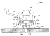
本発明の第七の例示的具体例において、器具は、単一ユニットに一体化されたもう一つの注入セットおよび挿入具を含み、それにより、この場合もまた、いかなる付加的な付属品をも携行する必要性を消去し、各回の使用で挿入具に注入セットを装着することに付随する困難性を回避し得る。 In a seventh exemplary embodiment of the present invention, the instrument includes another infusion set and insert integrated into a single unit, thereby again with any additional accessories. The need to carry can be eliminated and the difficulties associated with mounting the infusion set on the inserter with each use can be avoided.
図38は、本発明の第七の具体例に従った、一体化された挿入具およびセットを利用する例示的器具500の図である。器具500は、上方ハウジング510を含み、そこからトリガー520が延出する。上方ハウジング510内に、カテーテルセプタム542を有する針ハブ540、カテーテル544および誘導針546が、トリガー520によって上方の格納位置に保持される。カテーテル組立体540は、ばね550によって、上方ハウジングに柔軟に結合されている。特に、渦巻きばね、または同様のばねが、図39に示される、上方ハウジング内のゼロエネルギー位置で、カテーテル組立体540を保持するように設けられる。そうすることで、ばね550は、図39に示されるように、カテーテル組立体540の運動の軸を可能にする。ハウジング510の基部は、以下に、より詳細に説明されるように、下方位置でカテーテルセプタム542を拘束するラッチ512を含み得る。接着ライナーが、器具の底部の、感圧接着剤(PSA)のような接着剤層504を覆うように設けられ得る。
FIG. 38 is an illustration of an
現在の衝撃挿入具において、挿入具機構は、作動化後一つの位置に移行し、誘導針は、それから、露出した針の先端を残す次の段階で後退させられる。しかし、円筒状バレルに収容され、動作の方向に垂直な、予め組み込まれた、中央の開口に針ハブを備えた渦巻きばねの使用は、単一段階で、配置と後退を達成することができる。解放で、ばねは、誘導針とカテーテルを皮膚表面に駆動し得、するとすぐ、渦巻きばねの設計と位置付けによって、誘導針は、皮膚表面から、後退するか、跳ね返る。誘導針は、円筒状バレルハウジング内に後方に引き込まれ、効果的に、誘導針を除去し、誘導針が、配置の間、露出されないので、使用者に安全性を提供する。 In current impact inserts, the inserter mechanism moves to one position after activation, and the guide needle is then retracted in the next stage leaving an exposed needle tip. However, the use of a spiral spring housed in a cylindrical barrel and pre-installed with a central hub with a needle hub perpendicular to the direction of movement can achieve placement and retraction in a single step. . Upon release, the spring can drive the introducer needle and catheter to the skin surface, and as soon as the spiral spring is designed and positioned, the introducer needle retracts or rebounds from the skin surface. The guide needle is retracted back into the cylindrical barrel housing, effectively removing the guide needle and providing safety to the user because the guide needle is not exposed during placement.
特に、ばね550は、ゼロエネルギー位置で、上方ハウジング510と針ハブ540の間に固定される。針ハブ540は、それから、図40Aに示されるように、トリガー520によって解放可能に固定される。そのようなトリガー520の構造は、当業者に良く知られており、したがって、さらなる説明は提供されない。トリガー520は、上方位置で、針ハブ540を解放可能に保持し、ばね550に、蓄えられたエネルギーを与える。解放により、ばね550は、図40Bに示されるように、皮膚表面に向けて針ハブ540を推進する。特に、解放により、カテーテルセプタム542を含む針ハブ540、カテーテル544および誘導針546は、図40Cおよび40Dに示されるように、皮膚表面に向け、ばね550によって駆動される。完全な配置で、ばね550は、針ハブ540および誘導針546を皮膚表面から離れるように推進し、図40Eに示されるように、下方位置に、カテーテルセプタム542およびカテーテル544を残す。
In particular, the
以下の式(1)に示されるように、正弦波が、使用中のばね力を現すために用いられ得、位置XUで、ばねの潜在エネルギーは最大で、力は最小となり、位置X1で、力は、ゼロエネルギー位置を通過して皮膚に向かい、位置X2で、力は皮膚に向かい、皮膚表面と係合してラッチし、位置X3で、力は、皮膚表面に背を向ける。 As shown in equation (1) below, a sine wave can be used to represent the spring force in use, at position XU, the spring's potential energy is maximum, and the force is minimum, at position X1, The force passes through the zero energy position towards the skin, at position X2, the force goes towards the skin and engages and latches on the skin surface, and at position X3 the force turns back against the skin surface.

器具は、静的に動作しないだろうし、位置XUでの事前の位置決めを必要とし、推進力を生成するために解放される。さらに、適正な操作のために要求される挿入エネルギーを超えない、推進力損失を有するだろう。適正な操作を確実にするために、以下の式(2)が満たされなければならず、WLは、損失である。 The instrument will not operate statically, requires pre-positioning at position XU, and is released to generate propulsion. Furthermore, it will have a propulsion loss that does not exceed the insertion energy required for proper operation. In order to ensure proper operation, the following equation (2) must be satisfied, and WL is a loss.
X2でのラッチ512の反応は、衝撃によるX3での跳ね返りより早くなければならない。ラッチングが挿入で設けられると、観察されるであろうものが、以下の式(3)に示され得、ラッチングが挿入で設けられないと、観察されるであろうものは、以下の式(4)に示され得、組織挿入におけるエネルギー損失による減衰は、式(3)および(4)の両方において、振幅に減少をもたらすであろう。
The response of
具体例は、どんな皮膚の状態においても、エネルギー損失を満たすように形成され得、ラッチ512は、以下の式(5)に示されているように、要望どおりに対応するように形成されている。
An example can be configured to satisfy energy loss in any skin condition, and the
示された例示的具体例において、器具500は円形形状を有するが、それに限定されない。器具の形状は、いくつもの形状に形成され得るが、渦巻きばねの作動を許容する円形部分を有する。ラインセット502が、それから、器具に取り付けられ得、医薬ポンプまたは他の供給容器に接続され得る。接着ライナーが、器具の底部で、感圧接着剤(PSA)のような、接着剤層504を覆うように設けられ得る。
In the exemplary embodiment shown, the
例示的使用において、使用者は、下面から接着ライナーを除去し、器具の底部の接着剤層504を露出させる。この位置において、針ハブ540、カテーテルセプタム542、カテーテル544および誘導針546は、上方ハウジング内に格納させられ、トリガー520によって保持される。器具500は、それから、露出した接着剤層504を用いて注入部位に固定され得る。このことは、使用者が、針ハブ540、カテーテルセプタム542、カテーテル544および誘導針546の配置を実行する前に、器具500が、皮膚表面に完全に接触し、接着して固定されることを確実にする。使用者は、それから、器具500のトリガー520を押圧し、ばね550を解放して、針ハブ540、カテーテルセプタム542、カテーテル544および誘導針546を、注入部位での所定の位置に駆動し、もし設けられるなら、それらは、ラッチ512によって保持され得る。連続したばね550のゼロエネルギー位置への移動は、針ハブ540および誘導針546を格納位置に駆動する。まだ接続されていなければ、チューブ502が、それから、ポンプまたは他の医薬供給部に接続され得る。
In an exemplary use, the user removes the adhesive liner from the bottom surface, exposing the
第七の具体例は、移動の方向に直角に、円筒バレル内に収容された、ハブを有する予め組み込まれた平坦な渦巻きばねに装着されている、誘導針およびカテーテルを含む。作動化により、ばねは解放して、使用者の皮膚に誘導針およびカテーテルを駆動し、そこで、ばねの設計および位置決めにより、誘導針は、皮膚に背を向けて後退し(すなわち、跳ね返り)、効果的に誘導針を除去し、露出した針が存在しないので、患者に安全性を提供する。 A seventh embodiment includes a guide needle and catheter mounted on a pre-assembled flat spiral spring with a hub housed in a cylindrical barrel, perpendicular to the direction of movement. Upon activation, the spring releases and drives the guide needle and catheter into the user's skin, where, due to the design and positioning of the spring, the guide needle retracts back against the skin (ie, rebounds) Effectively removes the guiding needle and provides safety to the patient because there is no exposed needle.
そのような設計は、より少ない部分および構成部品を有する、簡単な設計を備えて、挿入のための一段階作動と安全性を提供する。例えば、内部バレルも安全ばねも必要とされない。対照的に、従来の器具は、誘導針を除去するための分離した動作と、安全のために器具を遮蔽するもう一つの動作を必要とする。適正なバレル内半径位置に配置された、動作の方向に垂直な、平坦な渦巻きばねを利用することは、同軸において、器具が、二つの方向で作動することを可能にし、それゆえ、挿入、および、その後の誘導針の除去または後退を達成する。 Such a design comprises a simple design with fewer parts and components, providing a one-step operation and safety for insertion. For example, neither an internal barrel nor a safety spring is required. In contrast, conventional instruments require a separate operation to remove the guide needle and another operation to shield the instrument for safety. Utilizing a flat spiral spring placed in the proper barrel radial position and perpendicular to the direction of motion, coaxially allows the instrument to operate in two directions, hence insertion, And subsequent removal or retraction of the guide needle.
上述の本発明の例示的具体例は、導入針の先端が快適さのために後退させられるが、カテーテルの支持のために残り得る、ハブと一体の挿入を組み込んでいる。上述の本発明の他の例示的具体例は、また、ハブと一体の挿入を組み込むが、柔軟な留置の鋼製針またはカテーテルが、皮膚に残され、類似の良い結果を示すように設けられ得る。しかし、他の例示的具体例において、分離した、または、非一体の挿入具が、また、極めて低い外形のハブおよびセットを提供するために用いられ得る。この場合、誘導針および/または駆動機構は、分離した、除去可能な挿入具と共に残り得る。 The exemplary embodiment of the invention described above incorporates an integral insertion with the hub where the tip of the introducer needle is retracted for comfort but can remain for catheter support. Other exemplary embodiments of the present invention described above also incorporate an integral insertion with the hub, but a flexible indwelling steel needle or catheter is provided on the skin to provide similar good results. obtain. However, in other exemplary embodiments, separate or non-integral inserts can also be used to provide a very low profile hub and set. In this case, the guide needle and / or drive mechanism may remain with a separate, removable insert.
本発明の第八例示的具体例において、器具は、単一ユニットに予め組み立てられた、単一使用の注入セットおよび挿入器具を含み、それによって、この場合もまた、少なくとも、分離した付属品を携行し、および組み立てる必要性を消去し、各回の使用において、挿入器具に注入セットを装着することに付随する複雑さを回避する。 In an eighth exemplary embodiment of the invention, the instrument comprises a single use infusion set and insertion instrument pre-assembled into a single unit, thereby again comprising at least a separate accessory. Eliminates the need to carry and assemble, and avoids the complications associated with mounting the infusion set on the inserter in each use.
図41〜43は、本発明の第三具体例に従った挿入具および注入セットを用いる例示的器具600の図である。器具600は、それから使用者押しボタン620が延びる、挿入器具610を含む。挿入器具610は、さらに、注入部位での配置のために遠位端に注入セット650を含む。配置の間、カテーテル630は、挿入器具610の作動の間に、注入セット650のセットハブ640の底面から延出され得る。図44は、その構成要素をより詳細に示す、図41の例示的器具の断面図である。
FIGS. 41-43 are diagrams of an
図41に示されるように、挿入器具610は、配置のために遠位端に注入セット650を含む。接着剤層636を覆う、接着性の引っ張りライナー635が、挿入器具610の遠位端をシールし、固定するために用いられ得る。挿入器具610は、さらに、押しボタン620が配置された、側面の開口を含む。押しボタン620は、延出した位置から実質的に平坦な位置まで、皮膚表面に実質的に平行に滑動可能に移動するよう形成されている。そうすることで、押しボタン620は、挿入器具610の駆動機構を解放し、注入部位における配置のために、注入セット650にカテーテルホルダー612を移動させるように形成されている。
As shown in FIG. 41, the
コアの独立したカテーテルホルダー612は、カテーテル630と共にハブ640内に配置され、皮膚表面に固定される。本発明の例示的具体例において、挿入ばね機構(不図示)が、付勢された状態で挿入器具内に配置され、その結果、押しボタン620の移動は、ばねを解放し、独立のカテーテルホルダー612を配置する。そのような駆動機構の創出は、当業者に良く知られており、それゆえ、更なる説明は提供されない。
A core
図44に示されるように、挿入器具610は、注入セット650上の位置に、独立したカテーテルホルダー612を含む。図45により詳細に示されるように、独立したカテーテルホルダー612は、主体618およびカテーテル630を取り囲み、支持する、柔軟性または弾性部材614を含む。作動させられると、独立したカテーテルホルダー612、外側の柔軟性、または、弾性部材614、主体618およびカテーテル630は、注入部位630へ、下方に駆動させられる。外方の柔軟性、または、弾性部材614は、ハブ640の開口616によって所定の位置に中心付けられ、保持される。開口616は、所定位置にあるとき、外方の柔軟性、または、弾性部材を、拘束し、保持することを支援するための、肩部またはディテント624を含み得る。主体618は、ハブ640内の開口622と自動的に整列するための、丸められた遠位端626を有する。カテーテル624は、ハブ640内に整列させられ、位置付けられるが、柔軟性、または、弾性部材614とハブ640内の開口616との間の係合によって、運動から分離される。
As shown in FIG. 44, the
ハブ640は、さらに、医薬ポンプまたは他の供給容器に接続され得る、チューブ結合642を含む。接着ライナー635が、ハブ640の底部の、感圧接着剤(PSA)のような、接着剤層636を覆うように設けられ得る。
図46A〜46Fは、使用中の、図41の例示的器具600の図である。図46Aの第一段階において、使用者は、下面から接着ライナー635を除去し、器具600の底の接着剤層636を露出させる。器具600のハブ640は、それから、図46Bに示されるように、露出した接着剤層636を用いて注入部位に固定され得る。このことは、使用者が、カテーテル630の配置を実行する前に、器具600のハブ640が、皮膚表面に完全に接触し、接着して固定されることを確実にする。使用者は、それから、図46Cに示されるように、器具600のボタン620を押圧し、単一動作で、誘導針およびカテーテル、または、自動配置の、留置カテーテル630を挿入し得る。挿入器具610は、それから、除去され、その後、図46D〜46Fに示されるように、チューブ642が、インスリン注入ポンプまたは他の医薬供給部644に接続され得る。
46A-46F are diagrams of the
本発明の第八の例示的具体例において、使用者は、皮膚表面に完全な器具を取り付け、それから、独立したカテーテルホルダーおよびカテーテルを配置し得、取り付けられるとき接着剤のいかなる集積をも防止すると共に、カテーテルが挿入される前に、セットのハブが完全に皮膚に接触し、接着で固定されることを確実にする。このことは、また、カテーテルが、正確な深さに挿入されることを確実にする。 In an eighth exemplary embodiment of the present invention, the user can attach the complete device to the skin surface and then place a separate catheter holder and catheter to prevent any accumulation of adhesive when attached. At the same time, before the catheter is inserted, it is ensured that the hub of the set is in full contact with the skin and secured with adhesive. This also ensures that the catheter is inserted to the correct depth.
例示的な器具は、さらに、独立したカテーテルホルダー612の「浮動カテーテル」態様を提供し、カテーテル組立体は、柔軟に、または、弾性的に、ハブ内に懸架され、または、支持されて、本体の移動、不測の衝突および/またはチューブの引っ張りによる運動を弱める。器具は、カテーテルを挿入するため、使用者が、単に、器具のボタンを押すことを求められるという、自動的な配置の方法を使用する。
The exemplary instrument further provides a “floating catheter” aspect of an
上述したように、従来のシステムにおいては、誘導針、カテーテルおよび接着剤は、全て、実質的に同時に配置され、そのような衝撃的な挿入の間、接着剤パッドの高速接触が存在する一方で、誘導針およびカテーテルが挿入され、それは、部分的に挿入されたカテーテルおよび/または不完全な接着をもたらし得る。本発明の例示的な第八の具体例は、システムおよび方法が、最初に、セットのハブが、皮膚表面に完全に接触し、接着で固定されることを確実にし、その後、カテーテルの配置を実行するため、カテーテルの部分的な挿入および/または不完全な接着の可能性を消去する。さらに、カテーテル組立体は、ハブ内で「浮動」であるように形成されており、本体の移動、不測の衝突および/またはチューブの引っ張りによる運動を弱めることに役立つ。 As noted above, in conventional systems, the guide needle, catheter and adhesive are all placed substantially simultaneously, while there is high speed contact of the adhesive pad during such shock insertion. A guide needle and catheter are inserted, which can result in a partially inserted catheter and / or incomplete adhesion. The eighth exemplary embodiment of the present invention is that the system and method first ensure that the hub of the set is in full contact with the skin surface and secured with adhesive, and then the placement of the catheter. To do so, eliminate the possibility of partial catheter insertion and / or incomplete adhesion. In addition, the catheter assembly is configured to be “floating” within the hub, which helps to reduce movement due to body movement, accidental impact and / or tube pull.
本発明の例示的な第八の具体例は、使用者が、挿入器具内に注入セットを装着することを求められないため、注入セットを挿入するために必要とされる段階を著しく減少する。さらに、先鋭な先端を有する柔軟性カテーテルは、使用および挿入の前に使用者から隔離されており、これは、器具をより安全にし、針に困惑する使用者に訴える。 The eighth exemplary embodiment of the present invention significantly reduces the steps required to insert the infusion set because the user is not required to wear the infusion set within the insertion tool. In addition, a flexible catheter with a sharp tip is isolated from the user prior to use and insertion, which makes the instrument safer and appeals to the user who is confused with the needle.
上述したように、器具は、第一段階において、使用者が、皮膚表面に器具を取り付け、それから、第二段階において、誘導針を配置するように形成されており、それにより、取り付けられるとき接着剤のいかなる集積をも防止する一方で、誘導針が挿入される前に、セットのハブが完全に皮膚に接触することを確実にする。このことは、また、カテーテルが正しい深さで挿入されることを確実にする。さらに、カテーテルは、ハブ内で、「浮動」に形成されており、それは、本体の移動、ハブへの不測の衝突および/またはチューブの引っ張りによる運動を弱めることに役立つ。 As described above, the device is configured such that, in the first stage, the user attaches the device to the skin surface, and then in the second stage, places the introducer needle so that it adheres when attached. While preventing any accumulation of agent, ensure that the hub of the set is in full contact with the skin before the introducer needle is inserted. This also ensures that the catheter is inserted at the correct depth. In addition, the catheter is formed “floating” within the hub, which helps to reduce movement due to body movement, accidental impact on the hub and / or tube pull.
本発明の例示的具体例において、ハウジング、ハブおよび他の要素は、モールド成形されたプラスチック材料、ポリカーボネート、ポリエチレンテレフタレート(PETおよびPETG)のような熱可塑性プラスチック、または、類似の材料で構成され得る。ばねおよび誘導針は、ステンレス鋼または類似の材料で構成され得る。上述の具体例は、皮下注射用の大きさとされ、皮下注射用に形成されているが、それらは、また、皮内または筋肉内注射のような、他のタイプの注射に用いられ得る。 In an exemplary embodiment of the invention, the housing, hub and other elements may be constructed of molded plastic material, polycarbonate, thermoplastics such as polyethylene terephthalate (PET and PETG), or similar materials. . The spring and guide needle may be constructed of stainless steel or similar material. The embodiments described above are sized for subcutaneous injection and are configured for subcutaneous injection, but they can also be used for other types of injection, such as intradermal or intramuscular injection.
さらに、本発明の一つ以上の例示的具体例は、皮膚接触接着剤層および裏当てを備えることができる。実際の挿入は、最初に、接着剤層を介して、注入部位に、注入セットのハブを固定することによって達成され、このことは、使用者が、挿入具を作動化させ、適正な整列で、上述のようにカテーテルを配置することを可能にする。そうすることで、誘導針は、制御された高速度で皮膚に駆動され、誘導針の挿入でテンティングの危険を最小化する。さらに、挿入部位での、または、きわめて近い部位での接着剤は、皮膚表面を固定し、挿入の間、皮膚表面のテンティングを最小化する。 Further, one or more exemplary embodiments of the present invention can comprise a skin contact adhesive layer and a backing. The actual insertion is accomplished by first securing the hub of the infusion set to the infusion site via an adhesive layer, which allows the user to activate the inserter with proper alignment. Allowing the catheter to be placed as described above. In doing so, the guide needle is driven into the skin at a controlled and high speed, and insertion of the guide needle minimizes the risk of tenting. Furthermore, the adhesive at or near the insertion site secures the skin surface and minimizes skin surface tenting during insertion.
皮下層へインスリンまたは他の医薬を送達する現行の注入セットにおいて、カテーテルは、カテーテルに伝達され、その後、カテーテルが皮膚内を移動するとき、痛みを引き起こし得る、いかなる望ましくない外力からも隔離されない。また、他の器具は、カテーテルが外力から隔離されないなら、器具がはねつけられるとき、早過ぎるか、または、意図されないカテーテルの除去の問題に直面する。本発明の例示的具体例において、カテーテルは、少なくとも一つの柔軟性または弾性構造によって、外力から隔離され得る。 In current infusion sets that deliver insulin or other medication to the subcutaneous layer, the catheter is transmitted to the catheter and is not isolated from any undesired external forces that can cause pain as the catheter subsequently moves through the skin. Also, other instruments face premature or unintended catheter removal problems when the instrument is repelled if the catheter is not isolated from external forces. In an exemplary embodiment of the invention, the catheter can be isolated from external forces by at least one flexible or elastic structure.
さらにまた、多くの市販の注入セットは、分離した挿入具の使用を要求する。ここに記載された本発明の例示的なハブ一体型の挿入の具体例において、使用者は、分離した挿入具を携行し、挿入具に、注入セットを装着する必要がない。一体型のシステムは、使用者が、分離した挿入具の携行および装着から自由であり、改良された便利さおよびより簡単な操作をもたらす。 Furthermore, many commercially available infusion sets require the use of a separate inserter. In the exemplary hub-integrated insertion embodiment of the present invention described herein, the user does not have to carry a separate insert and attach the infusion set to the insert. The integrated system frees the user from carrying and mounting a separate insert, resulting in improved convenience and easier operation.
本発明のいくつかの例示的具体例が詳細に上述されたが、当業者は、この発明の新規な教示および利点から実質的に離れることなく、例示的具体例に多くの変形が可能であることを、容易に理解するであろう。したがって、全てのそのような変形は、添付の特許請求の範囲に規定された発明、および、その均等物の範囲に含まれることを意図されている。 Although several exemplary embodiments of the present invention have been described above in detail, those skilled in the art can make many variations to the exemplary embodiments without substantially departing from the novel teachings and advantages of the present invention. You will understand that easily. Accordingly, all such modifications are intended to be included within the scope of the invention as defined in the appended claims and equivalents thereof.
Claims (25)
前記皮膚表面に前記カテーテルおよび前記カテーテルを配置するためのドライバを含む注入器具ハウジングと、
注入器具基部を前記皮膚表面に解放可能に固定するための少なくとも一つの接着剤層を含む前記注入器具基部と、
誘導針およびカテーテルセプタムを含み、
前記ドライバは、第1ばねによって付加される力によって、前記注入器具ハウジング内で回転し、前記誘導針と前記カテーテルを前記皮膚表面に押圧するように形成された回転針ハブを含み、
前記回転針ハブは、前記第1ばねによって付加される力によって、前記注入器具ハウジング内でさらに回転し、前記カテーテルから前記誘導針を後退させるように形成されていることを特徴とする注入器具。 An infusion device comprising an inserter capable of inserting a catheter into the skin surface,
An infusion device housing including the catheter and a driver for placing the catheter on the skin surface;
The infusion device base including at least one adhesive layer for releasably securing the infusion device base to the skin surface ;
Including a guide needle and a catheter septum,
The driver includes a rotating needle hub configured to rotate within the infusion device housing by a force applied by a first spring and press the guide needle and the catheter against the skin surface;
The infusion device, wherein the rotating needle hub is formed to further rotate in the infusion device housing by a force applied by the first spring and to retract the guide needle from the catheter .
前記ドライバは、前記皮膚表面に実質的に垂直に移動し、前記カテーテルセプタムを前記皮膚表面に向って押圧し、前記誘導針と前記カテーテルを前記皮膚表面に挿入するように形成された押しボタンを含むことを特徴とする注入器具。 An injection device according to claim 1,
The driver includes a push button configured to move substantially perpendicular to the skin surface, press the catheter septum toward the skin surface, and insert the guide needle and the catheter into the skin surface. An injection device characterized by comprising.
前記基部は、前記カテーテルセプタムを摺動可能に受容するためのセプタム開口部を含み、該セプタム開口部は、流路開口部を含み、
前記カテーテルセプタムは、流路開口部を含み、
前記カテーテルは、流路開口部を含み、これらの流路開口部は、前記誘導針と前記カテーテルが前記皮膚表面に挿入されるとき、整列することを特徴とする注入器具。 An injection device according to claim 2,
The base includes a septum opening for slidably receiving the catheter septum, the septum opening including a flow path opening;
The catheter septum includes a channel opening;
The infusion device, wherein the catheter includes a channel opening, and the channel opening is aligned when the guide needle and the catheter are inserted into the skin surface.
Applications Claiming Priority (3)
| Application Number | Priority Date | Filing Date | Title |
|---|---|---|---|
| US201161441265P | 2011-02-09 | 2011-02-09 | |
| US61/441,265 | 2011-02-09 | ||
| PCT/US2012/000069 WO2012108955A2 (en) | 2011-02-09 | 2012-02-08 | Subcutaneous infusion device |
Publications (2)
| Publication Number | Publication Date |
|---|---|
| JP2014510571A JP2014510571A (en) | 2014-05-01 |
| JP6006239B2 true JP6006239B2 (en) | 2016-10-12 |
Family
ID=46639118
Family Applications (1)
| Application Number | Title | Priority Date | Filing Date |
|---|---|---|---|
| JP2013553431A Active JP6006239B2 (en) | 2011-02-09 | 2012-02-08 | Subcutaneous injection device |
Country Status (7)
| Country | Link |
|---|---|
| US (3) | US10342918B2 (en) |
| EP (2) | EP2673023B1 (en) |
| JP (1) | JP6006239B2 (en) |
| CN (1) | CN203898932U (en) |
| CA (3) | CA2826094C (en) |
| ES (1) | ES2732080T3 (en) |
| WO (1) | WO2012108955A2 (en) |
Families Citing this family (75)
| Publication number | Priority date | Publication date | Assignee | Title |
|---|---|---|---|---|
| PL1762259T3 (en) | 2005-09-12 | 2011-03-31 | Unomedical As | An inserter for an infusion set with first and second spring units |
| DK2626093T3 (en) * | 2008-08-28 | 2014-02-24 | Hoffmann La Roche | DEVICE FOR INCREASING HYPODERMIC insulin absorption |
| BR112012024635A2 (en) | 2010-03-30 | 2017-08-08 | Unomedical As | medical device |
| US8915879B2 (en) | 2010-09-24 | 2014-12-23 | Perqflo, Llc | Infusion pumps |
| US8905972B2 (en) | 2010-11-20 | 2014-12-09 | Perqflo, Llc | Infusion pumps |
| JP6118734B2 (en) * | 2011-02-09 | 2017-04-19 | ベクトン・ディキンソン・アンド・カンパニーBecton, Dickinson And Company | Self-contained torsion spring inserter for drug delivery infusion sets |
| WO2012123274A1 (en) | 2011-03-14 | 2012-09-20 | Unomedical A/S | Inserter system with transport protection |
| US8882711B2 (en) | 2011-09-30 | 2014-11-11 | Animas Corporation | Insertion device for a medical conduit |
| WO2013050277A1 (en) | 2011-10-05 | 2013-04-11 | Unomedical A/S | Inserter for simultaneous insertion of multiple transcutaneous parts |
| EP2583715A1 (en) | 2011-10-19 | 2013-04-24 | Unomedical A/S | Infusion tube system and method for manufacture |
| CA3066834C (en) | 2011-12-07 | 2022-04-12 | Becton, Dickinson And Company | Needle shielding assemblies and infusion devices for use therewith |
| CA3043582C (en) | 2011-12-07 | 2022-06-07 | Becton, Dickinson And Company | Infusion device with releasable fluid connector |
| USD747456S1 (en) * | 2012-12-07 | 2016-01-12 | Becton, Dickinson And Company | Infusion set assembly |
| USD747458S1 (en) * | 2012-12-07 | 2016-01-12 | Becton, Dickinson And Company | Infusion set insertion needle assembly |
| USD756504S1 (en) * | 2012-12-07 | 2016-05-17 | Becton, Dickinson And Company | Infusion set base |
| USD747459S1 (en) * | 2012-12-07 | 2016-01-12 | Becton, Dickinson And Company | Infusion set assembly |
| USD754842S1 (en) * | 2012-12-07 | 2016-04-26 | Becton, Dickinson And Company | Infusion set needle guard |
| USD747457S1 (en) * | 2012-12-07 | 2016-01-12 | Becton, Dickinson And Company | Infusion set needle guard |
| USD754843S1 (en) * | 2012-12-07 | 2016-04-26 | Becton, Dickinson And Company | Infusion set assembly |
| US9821113B2 (en) * | 2013-03-15 | 2017-11-21 | Becton, Dickinson And Company | Automatic angled infusion set assembly |
| CN206518747U (en) * | 2014-04-24 | 2017-09-26 | 贝克顿·迪金森公司 | Catheter insertion apparatus |
| CA2943709C (en) * | 2014-04-24 | 2022-07-05 | Becton, Dickinson And Company | Catheter insertion device |
| US10195342B2 (en) | 2014-04-24 | 2019-02-05 | Becton, Dickinson And Company | Cannula deployment mechanism |
| CN206183752U (en) * | 2014-04-24 | 2017-05-24 | 贝克顿·迪金森公司 | Fluid infusion device |
| US12178992B2 (en) | 2014-09-30 | 2024-12-31 | Medtronic Minimed, Inc. | Different disposable assemblies for the same reusable assembly |
| US10159786B2 (en) | 2014-09-30 | 2018-12-25 | Perqflo, Llc | Hybrid ambulatory infusion pumps |
| MX2017010278A (en) * | 2015-02-10 | 2018-03-23 | Amgen Inc | Rotationally biased insertion mechanism for a drug delivery pump. |
| EP3258989B1 (en) | 2015-02-18 | 2020-01-01 | Medtronic Minimed, Inc. | Ambulatory infusion pump with static and dynamic seals |
| KR102701011B1 (en) * | 2015-03-09 | 2024-08-29 | 암겐 인코포레이티드 | Drive mechanism for drug delivery pump |
| WO2016196934A1 (en) | 2015-06-04 | 2016-12-08 | Medimop Medical Projects Ltd. | Cartridge insertion for drug delivery device |
| EP3352814B1 (en) * | 2015-09-22 | 2024-04-10 | Thomas Jefferson University | Continuous subcutaneous insulin infusion catheter |
| US20170203053A1 (en) * | 2016-01-19 | 2017-07-20 | Joseph Choate Burkett | Visual-Assisted Insertion Device |
| CN108778370B (en) | 2016-01-19 | 2021-10-08 | 优诺医疗有限公司 | Cannula and infusion device |
| WO2017139003A1 (en) * | 2016-02-10 | 2017-08-17 | Unitract Syringe Pty Ltd. | Drug delivery device |
| JOP20170042B1 (en) * | 2016-02-12 | 2022-09-15 | Amgen Inc | Drug Delivery Device, Method of Manufacture and Method of Use |
| EP3413954A1 (en) | 2016-02-12 | 2018-12-19 | Perqflo, LLC | Ambulatory infusion pumps and assemblies for use with same |
| KR101764813B1 (en) * | 2016-02-29 | 2017-08-03 | 중소기업은행 | Cover and device for infusing medical liquid including the same |
| KR101754981B1 (en) * | 2016-02-29 | 2017-07-06 | 중소기업은행 | Apparatus for Infusing medical liquid |
| TWI750163B (en) | 2016-04-08 | 2021-12-21 | 美商安美基公司 | Drug delivery device and system |
| ES2794973T3 (en) * | 2016-05-11 | 2020-11-20 | Becton Dickinson Co | Insertion needle safety module |
| US10603445B2 (en) * | 2016-06-09 | 2020-03-31 | Becton, Dickinson And Company | Needle actuator assembly for drug delivery system |
| CN109562222B (en) * | 2016-08-12 | 2022-09-02 | 赛诺菲-安万特德国有限公司 | Drug delivery device |
| KR101928297B1 (en) * | 2016-09-08 | 2018-12-12 | 이오플로우(주) | Medical fluid delivery device |
| WO2018060023A1 (en) | 2016-09-27 | 2018-04-05 | Sanofi-Aventis Deutschland Gmbh | A medicament delivery device |
| EP3354303B1 (en) * | 2017-01-31 | 2020-01-08 | Société Industrielle de Sonceboz S.A. | Drug delivery system |
| US10413658B2 (en) | 2017-03-31 | 2019-09-17 | Capillary Biomedical, Inc. | Helical insertion infusion device |
| US11819666B2 (en) | 2017-05-30 | 2023-11-21 | West Pharma. Services IL, Ltd. | Modular drive train for wearable injector |
| US11260171B2 (en) * | 2017-07-04 | 2022-03-01 | Medtronic Minimed, Inc. | Ambulatory infusion pumps and assemblies for use with same |
| CA3069278A1 (en) | 2017-07-07 | 2019-01-10 | Neuroderm Ltd | Device for subcutaneous delivery of fluid medicament |
| US20230123806A1 (en) | 2017-07-07 | 2023-04-20 | Neuroderm, Ltd. | Device for subcutaneous delivery of fluid medicament |
| US11305067B2 (en) | 2017-08-10 | 2022-04-19 | West Pharma. Services IL, Ltd. | Activation button assembly and injection needle insertion mechanism for injector |
| CN107320811A (en) * | 2017-08-15 | 2017-11-07 | 郑州蒙纳瑞医疗设备有限公司 | A kind of repeatable remain-type subcutaneous infusion set utilized |
| JP7143305B2 (en) * | 2017-09-08 | 2022-09-28 | テルモ株式会社 | lancing device |
| US10632280B2 (en) * | 2017-09-15 | 2020-04-28 | Neosinus Health Inc. | Devices and methods for delivering fluid to a nasal cavity |
| US10869961B2 (en) | 2017-11-06 | 2020-12-22 | Sorrel Medical Ltd. | Local disinfection for drug delivery system |
| CN111683703B (en) | 2017-12-22 | 2022-11-18 | 西氏医药包装(以色列)有限公司 | Syringes for different sized cartridges |
| US10980938B2 (en) * | 2018-03-08 | 2021-04-20 | Flex Ltd. | Double action rigid fluid path connector |
| KR102111732B1 (en) * | 2018-08-14 | 2020-05-15 | 이오플로우(주) | Needle assembly and drug injection device comprising the same |
| WO2020051211A2 (en) * | 2018-09-04 | 2020-03-12 | Biolark, Inc. | Extended use infusion set for medical use |
| KR102500227B1 (en) * | 2018-09-22 | 2023-02-15 | 에스에이치엘 메디컬 아게 | Syringe Needle Insertion and Retraction Assembly |
| US11357909B2 (en) | 2018-10-05 | 2022-06-14 | Eitan Medical Ltd. | Triggering sequence |
| CN113646023B (en) | 2019-02-22 | 2023-07-21 | 德卡产品有限公司 | Infusion set and insert assembly systems and methods |
| CA3141608A1 (en) | 2019-05-20 | 2020-11-26 | Unomedical A/S | Rotatable infusion device and methods thereof |
| US11052205B2 (en) | 2019-06-11 | 2021-07-06 | Neosinus Health Inc | Devices and methods for delivering fluid to a nasal cavity |
| US12214159B2 (en) | 2020-08-28 | 2025-02-04 | Tandem Diabetes Care, Inc | Insulin infusion set |
| US11951281B2 (en) | 2020-11-11 | 2024-04-09 | Medtronic Minimed, Inc. | Fluid conduit insertion devices |
| US20220143306A1 (en) * | 2020-11-11 | 2022-05-12 | Medtronic Minimed, Inc. | Torsional insertion devices |
| AU2022205592A1 (en) * | 2021-01-05 | 2023-07-20 | Becton, Dickinson And Company | Drug delivery device with needle hub |
| CN117836023A (en) | 2021-07-23 | 2024-04-05 | 康沃特克有限公司 | Port with piercing mechanism |
| CN114306809B (en) * | 2021-12-31 | 2024-11-22 | 深圳市阿瑞医疗电子有限公司 | A balanced indwelling needle assembly and a patch-type liquid medicine infusion system |
| CN114344617B (en) * | 2022-01-13 | 2023-09-22 | 上海旭润医学科技有限责任公司 | Auxiliary needle insertion device for application type continuous subcutaneous drug delivery system |
| USD1057941S1 (en) | 2022-08-26 | 2025-01-14 | Deka Products Limited Partnership | Patient care assembly component |
| USD1043976S1 (en) | 2022-08-26 | 2024-09-24 | Deka Products Limited Partnership | Fluid transfer connector |
| WO2024173658A2 (en) * | 2023-02-17 | 2024-08-22 | Aita Bio Inc. | Needle retraction assembly for a device for delivering insulin |
| US20250025627A1 (en) * | 2023-07-21 | 2025-01-23 | Medtronic Minimed, Inc. | Medicament infusion device |
Family Cites Families (49)
| Publication number | Priority date | Publication date | Assignee | Title |
|---|---|---|---|---|
| US3918355A (en) * | 1972-08-24 | 1975-11-11 | Robert L Weber | Infusion apparatus and method |
| US5129884A (en) | 1990-01-16 | 1992-07-14 | Dysarz Edward D | Trap in barrel one handed retracted intervenous catheter device |
| US5993470A (en) | 1992-09-15 | 1999-11-30 | Yoon; Inbae | Universal handle for medical instruments |
| US6607509B2 (en) | 1997-12-31 | 2003-08-19 | Medtronic Minimed, Inc. | Insertion device for an insertion set and method of using the same |
| US6485461B1 (en) | 2000-04-04 | 2002-11-26 | Insulet, Inc. | Disposable infusion device |
| ATE363922T1 (en) | 2000-09-08 | 2007-06-15 | Insulet Corp | INFUSION DEVICE AND SYSTEM |
| WO2002028454A2 (en) | 2000-10-04 | 2002-04-11 | Insulet Corporation | Data collection assembly for patient infusion system |
| WO2002040083A2 (en) | 2000-11-09 | 2002-05-23 | Insulet Corporation | Transcutaneous delivery means |
| IL141574A0 (en) | 2001-02-21 | 2002-03-10 | Serpomed Ltd | Compact catheter insertion apparatus |
| US6960192B1 (en) * | 2002-04-23 | 2005-11-01 | Insulet Corporation | Transcutaneous fluid delivery system |
| US20040010207A1 (en) | 2002-07-15 | 2004-01-15 | Flaherty J. Christopher | Self-contained, automatic transcutaneous physiologic sensing system |
| US7128727B2 (en) | 2002-09-30 | 2006-10-31 | Flaherty J Christopher | Components and methods for patient infusion device |
| US7144384B2 (en) | 2002-09-30 | 2006-12-05 | Insulet Corporation | Dispenser components and methods for patient infusion device |
| EP1556103A1 (en) | 2002-10-07 | 2005-07-27 | Novo Nordisk A/S | Needle device comprising a plurality of needles |
| EP1624914B1 (en) * | 2003-05-08 | 2008-04-16 | Novo Nordisk A/S | Internal needle inserter |
| US6926694B2 (en) | 2003-05-09 | 2005-08-09 | Medsolve Technologies, Llc | Apparatus and method for delivery of therapeutic and/or diagnostic agents |
| DE20320207U1 (en) | 2003-06-12 | 2004-10-14 | Disetronic Licensing Ag | Insertion device for an infusion set comprises a thrust linkage which is constituted so that the forward motion of the set takes place without a sliding contact with the device housing |
| US20090012472A1 (en) | 2004-09-22 | 2009-01-08 | Novo Nordisk A/S | Medical Device with Cannula Inserter |
| US7867200B2 (en) | 2004-12-10 | 2011-01-11 | Unomedical A/S | Inserter |
| US9636450B2 (en) | 2007-02-19 | 2017-05-02 | Udo Hoss | Pump system modular components for delivering medication and analyte sensing at seperate insertion sites |
| US20090076451A1 (en) | 2005-01-24 | 2009-03-19 | Nova Nordisk A/S | Medical Device with Protected Transcutaneous Device |
| AU2006226988B2 (en) | 2005-03-21 | 2011-12-01 | Abbott Diabetes Care, Inc. | Method and system for providing integrated medication infusion and analyte monitoring system |
| ITVI20050152A1 (en) | 2005-05-20 | 2006-11-21 | Tecres Spa | CARTRIDGE FOR CONSERVATION AND STERILE DISTRIBUTION OF A BIPHASIC COMPOUND, PARTICULARLY FOR AN ACRYLIC RESIN |
| TWI257999B (en) * | 2005-07-29 | 2006-07-11 | Quanta Display Inc | Device for detecting a cracked substrate |
| PL1762259T3 (en) | 2005-09-12 | 2011-03-31 | Unomedical As | An inserter for an infusion set with first and second spring units |
| EP3165247B1 (en) | 2006-02-09 | 2020-10-28 | DEKA Products Limited Partnership | Pumping fluid delivery systems and methods using force application assembley |
| US7731118B2 (en) * | 2006-03-29 | 2010-06-08 | Martin-Baker Aircraft Co., Ltd. | Acceleration sensor |
| CN101460207B (en) | 2006-06-06 | 2012-03-21 | 诺沃-诺迪斯克有限公司 | Assembly comprising skin-mountable device and packaging therefore |
| US7789857B2 (en) | 2006-08-23 | 2010-09-07 | Medtronic Minimed, Inc. | Infusion medium delivery system, device and method with needle inserter and needle inserter device and method |
| JP2010517700A (en) | 2007-02-09 | 2010-05-27 | デカ・プロダクツ・リミテッド・パートナーシップ | Automatic insertion assembly |
| EP1970084B8 (en) | 2007-03-14 | 2010-09-22 | F. Hoffmann-La Roche Ltd. | Insertion device for an insertion head, in particular for an infusion set |
| EP2146760B1 (en) * | 2007-04-30 | 2018-10-10 | Medtronic MiniMed, Inc. | Reservoir filling, bubble management, and infusion medium delivery systems and methods with same |
| JP5277242B2 (en) | 2007-04-30 | 2013-08-28 | メドトロニック ミニメド インコーポレイテッド | Needle insertion and fluid flow connections for infusion medium delivery systems |
| US20080312582A1 (en) | 2007-06-15 | 2008-12-18 | Peter Krulevitch | Method for inserting a flexible medical device conduit |
| EP2155296B1 (en) | 2007-06-20 | 2019-08-28 | Unomedical A/S | Cannula insertion device with automatic needle retraction comprising only one spring |
| CN101754779B (en) * | 2007-07-18 | 2012-09-05 | 优诺医疗有限公司 | Inserter device with controlled acceleration |
| WO2009015389A2 (en) * | 2007-07-26 | 2009-01-29 | Entra Pharmaceuticals Inc. | Skin-patch pump comprising a changing-volume electrochemical actuator |
| US9968742B2 (en) | 2007-08-29 | 2018-05-15 | Medtronic Minimed, Inc. | Combined sensor and infusion set using separated sites |
| CA2699875A1 (en) | 2007-09-17 | 2009-03-26 | Icu Medical, Inc. | Insertion devices for infusion devices |
| DE102007049446A1 (en) | 2007-10-16 | 2009-04-23 | Cequr Aps | Catheter introducer |
| IL194805A0 (en) | 2007-10-29 | 2009-08-03 | Lifescan Inc | Medical device flexible conduit and method of manufacture |
| US9375529B2 (en) | 2009-09-02 | 2016-06-28 | Becton, Dickinson And Company | Extended use medical device |
| EP3677293A1 (en) | 2009-01-12 | 2020-07-08 | Becton, Dickinson and Company | In-dwelling rigid catheter with flexible features |
| US10092691B2 (en) | 2009-09-02 | 2018-10-09 | Becton, Dickinson And Company | Flexible and conformal patch pump |
| ES2881798T3 (en) * | 2010-03-24 | 2021-11-30 | Abbott Diabetes Care Inc | Medical device inserters and medical device insertion and use procedures |
| US8795230B2 (en) * | 2010-11-30 | 2014-08-05 | Becton, Dickinson And Company | Adjustable height needle infusion device |
| EP2495001A1 (en) | 2011-03-03 | 2012-09-05 | Debiotech S.A. | Cannula inserter |
| CN203694219U (en) | 2011-03-03 | 2014-07-09 | 贝克顿·迪金森公司 | Infusion assembly |
| EP3549524B1 (en) | 2012-03-30 | 2023-01-25 | Insulet Corporation | Fluid delivery device with transcutaneous access tool, insertion mechanism and blood glucose monitoring for use therewith |
-
2012
- 2012-02-08 JP JP2013553431A patent/JP6006239B2/en active Active
- 2012-02-08 EP EP12744352.1A patent/EP2673023B1/en active Active
- 2012-02-08 WO PCT/US2012/000069 patent/WO2012108955A2/en active Application Filing
- 2012-02-08 EP EP19157528.1A patent/EP3542852B1/en active Active
- 2012-02-08 CA CA2826094A patent/CA2826094C/en active Active
- 2012-02-08 CN CN201290000356.XU patent/CN203898932U/en not_active Expired - Lifetime
- 2012-02-08 CA CA3092628A patent/CA3092628C/en active Active
- 2012-02-08 CA CA3175799A patent/CA3175799A1/en active Pending
- 2012-02-08 US US13/984,029 patent/US10342918B2/en active Active
- 2012-02-08 ES ES12744352T patent/ES2732080T3/en active Active
-
2019
- 2019-05-17 US US16/415,784 patent/US11878143B2/en active Active
-
2023
- 2023-12-13 US US18/538,927 patent/US20240148964A1/en active Pending
Also Published As
| Publication number | Publication date |
|---|---|
| EP2673023B1 (en) | 2019-04-03 |
| US11878143B2 (en) | 2024-01-23 |
| WO2012108955A3 (en) | 2013-11-07 |
| ES2732080T3 (en) | 2019-11-20 |
| EP3542852C0 (en) | 2024-07-10 |
| CA2826094A1 (en) | 2012-08-16 |
| US20140058353A1 (en) | 2014-02-27 |
| CA3092628A1 (en) | 2012-08-16 |
| JP2014510571A (en) | 2014-05-01 |
| EP2673023A4 (en) | 2016-06-29 |
| US20200001005A1 (en) | 2020-01-02 |
| CA2826094C (en) | 2020-11-10 |
| CA3175799A1 (en) | 2012-08-16 |
| EP3542852B1 (en) | 2024-07-10 |
| CA3092628C (en) | 2022-12-13 |
| US20240148964A1 (en) | 2024-05-09 |
| US10342918B2 (en) | 2019-07-09 |
| CN203898932U (en) | 2014-10-29 |
| EP3542852A1 (en) | 2019-09-25 |
| WO2012108955A2 (en) | 2012-08-16 |
| EP2673023A2 (en) | 2013-12-18 |
Similar Documents
| Publication | Publication Date | Title |
|---|---|---|
| JP6006239B2 (en) | Subcutaneous injection device | |
| JP7203789B2 (en) | Integral spring-actuated shock insert for drug infusion device | |
| JP6592142B2 (en) | Infusion set assembly | |
| US6197001B1 (en) | Vascular access device | |
| EP1297859B1 (en) | Safety catheter | |
| EP1880741A1 (en) | Straight insertion safety infusion set | |
| US20080312600A1 (en) | Flexible medical device conduit | |
| WO2011160244A1 (en) | Device for inserting an insertion member into the tissue of the body of a patient | |
| KR20210013093A (en) | Syringe needle insertion and retraction assembly | |
| EP4000667A1 (en) | Torsional insertion devices |
Legal Events
| Date | Code | Title | Description |
|---|---|---|---|
| A621 | Written request for application examination |
Free format text: JAPANESE INTERMEDIATE CODE: A621 Effective date: 20150126 |
|
| A977 | Report on retrieval |
Free format text: JAPANESE INTERMEDIATE CODE: A971007 Effective date: 20151224 |
|
| A131 | Notification of reasons for refusal |
Free format text: JAPANESE INTERMEDIATE CODE: A131 Effective date: 20160126 |
|
| A521 | Request for written amendment filed |
Free format text: JAPANESE INTERMEDIATE CODE: A523 Effective date: 20160426 |
|
| TRDD | Decision of grant or rejection written | ||
| A01 | Written decision to grant a patent or to grant a registration (utility model) |
Free format text: JAPANESE INTERMEDIATE CODE: A01 Effective date: 20160809 |
|
| A61 | First payment of annual fees (during grant procedure) |
Free format text: JAPANESE INTERMEDIATE CODE: A61 Effective date: 20160908 |
|
| R150 | Certificate of patent or registration of utility model |
Ref document number: 6006239 Country of ref document: JP Free format text: JAPANESE INTERMEDIATE CODE: R150 |
|
| R250 | Receipt of annual fees |
Free format text: JAPANESE INTERMEDIATE CODE: R250 |
|
| R250 | Receipt of annual fees |
Free format text: JAPANESE INTERMEDIATE CODE: R250 |
|
| R250 | Receipt of annual fees |
Free format text: JAPANESE INTERMEDIATE CODE: R250 |
|
| R250 | Receipt of annual fees |
Free format text: JAPANESE INTERMEDIATE CODE: R250 |
|
| R250 | Receipt of annual fees |
Free format text: JAPANESE INTERMEDIATE CODE: R250 |