JP5277242B2 - Needle insertion and fluid flow connections for infusion medium delivery systems - Google Patents
Needle insertion and fluid flow connections for infusion medium delivery systems Download PDFInfo
- Publication number
- JP5277242B2 JP5277242B2 JP2010506179A JP2010506179A JP5277242B2 JP 5277242 B2 JP5277242 B2 JP 5277242B2 JP 2010506179 A JP2010506179 A JP 2010506179A JP 2010506179 A JP2010506179 A JP 2010506179A JP 5277242 B2 JP5277242 B2 JP 5277242B2
- Authority
- JP
- Japan
- Prior art keywords
- needle
- cannula
- housing
- plunger
- patient
- Prior art date
- Legal status (The legal status is an assumption and is not a legal conclusion. Google has not performed a legal analysis and makes no representation as to the accuracy of the status listed.)
- Expired - Fee Related
Links
Images


Classifications
-
- A—HUMAN NECESSITIES
- A61—MEDICAL OR VETERINARY SCIENCE; HYGIENE
- A61M—DEVICES FOR INTRODUCING MEDIA INTO, OR ONTO, THE BODY; DEVICES FOR TRANSDUCING BODY MEDIA OR FOR TAKING MEDIA FROM THE BODY; DEVICES FOR PRODUCING OR ENDING SLEEP OR STUPOR
- A61M5/00—Devices for bringing media into the body in a subcutaneous, intra-vascular or intramuscular way; Accessories therefor, e.g. filling or cleaning devices, arm-rests
- A61M5/14—Infusion devices, e.g. infusing by gravity; Blood infusion; Accessories therefor
- A61M5/1413—Modular systems comprising interconnecting elements
-
- A—HUMAN NECESSITIES
- A61—MEDICAL OR VETERINARY SCIENCE; HYGIENE
- A61M—DEVICES FOR INTRODUCING MEDIA INTO, OR ONTO, THE BODY; DEVICES FOR TRANSDUCING BODY MEDIA OR FOR TAKING MEDIA FROM THE BODY; DEVICES FOR PRODUCING OR ENDING SLEEP OR STUPOR
- A61M5/00—Devices for bringing media into the body in a subcutaneous, intra-vascular or intramuscular way; Accessories therefor, e.g. filling or cleaning devices, arm-rests
- A61M5/14—Infusion devices, e.g. infusing by gravity; Blood infusion; Accessories therefor
- A61M5/142—Pressure infusion, e.g. using pumps
- A61M5/14244—Pressure infusion, e.g. using pumps adapted to be carried by the patient, e.g. portable on the body
- A61M5/14248—Pressure infusion, e.g. using pumps adapted to be carried by the patient, e.g. portable on the body of the skin patch type
-
- A—HUMAN NECESSITIES
- A61—MEDICAL OR VETERINARY SCIENCE; HYGIENE
- A61M—DEVICES FOR INTRODUCING MEDIA INTO, OR ONTO, THE BODY; DEVICES FOR TRANSDUCING BODY MEDIA OR FOR TAKING MEDIA FROM THE BODY; DEVICES FOR PRODUCING OR ENDING SLEEP OR STUPOR
- A61M5/00—Devices for bringing media into the body in a subcutaneous, intra-vascular or intramuscular way; Accessories therefor, e.g. filling or cleaning devices, arm-rests
- A61M5/14—Infusion devices, e.g. infusing by gravity; Blood infusion; Accessories therefor
- A61M5/165—Filtering accessories, e.g. blood filters, filters for infusion liquids
-
- A—HUMAN NECESSITIES
- A61—MEDICAL OR VETERINARY SCIENCE; HYGIENE
- A61M—DEVICES FOR INTRODUCING MEDIA INTO, OR ONTO, THE BODY; DEVICES FOR TRANSDUCING BODY MEDIA OR FOR TAKING MEDIA FROM THE BODY; DEVICES FOR PRODUCING OR ENDING SLEEP OR STUPOR
- A61M5/00—Devices for bringing media into the body in a subcutaneous, intra-vascular or intramuscular way; Accessories therefor, e.g. filling or cleaning devices, arm-rests
- A61M5/36—Devices for bringing media into the body in a subcutaneous, intra-vascular or intramuscular way; Accessories therefor, e.g. filling or cleaning devices, arm-rests with means for eliminating or preventing injection or infusion of air into body
-
- A—HUMAN NECESSITIES
- A61—MEDICAL OR VETERINARY SCIENCE; HYGIENE
- A61M—DEVICES FOR INTRODUCING MEDIA INTO, OR ONTO, THE BODY; DEVICES FOR TRANSDUCING BODY MEDIA OR FOR TAKING MEDIA FROM THE BODY; DEVICES FOR PRODUCING OR ENDING SLEEP OR STUPOR
- A61M5/00—Devices for bringing media into the body in a subcutaneous, intra-vascular or intramuscular way; Accessories therefor, e.g. filling or cleaning devices, arm-rests
- A61M5/14—Infusion devices, e.g. infusing by gravity; Blood infusion; Accessories therefor
- A61M5/142—Pressure infusion, e.g. using pumps
- A61M5/14244—Pressure infusion, e.g. using pumps adapted to be carried by the patient, e.g. portable on the body
- A61M5/14248—Pressure infusion, e.g. using pumps adapted to be carried by the patient, e.g. portable on the body of the skin patch type
- A61M2005/14252—Pressure infusion, e.g. using pumps adapted to be carried by the patient, e.g. portable on the body of the skin patch type with needle insertion means
-
- A—HUMAN NECESSITIES
- A61—MEDICAL OR VETERINARY SCIENCE; HYGIENE
- A61M—DEVICES FOR INTRODUCING MEDIA INTO, OR ONTO, THE BODY; DEVICES FOR TRANSDUCING BODY MEDIA OR FOR TAKING MEDIA FROM THE BODY; DEVICES FOR PRODUCING OR ENDING SLEEP OR STUPOR
- A61M5/00—Devices for bringing media into the body in a subcutaneous, intra-vascular or intramuscular way; Accessories therefor, e.g. filling or cleaning devices, arm-rests
- A61M5/14—Infusion devices, e.g. infusing by gravity; Blood infusion; Accessories therefor
- A61M5/142—Pressure infusion, e.g. using pumps
- A61M5/14244—Pressure infusion, e.g. using pumps adapted to be carried by the patient, e.g. portable on the body
- A61M2005/14268—Pressure infusion, e.g. using pumps adapted to be carried by the patient, e.g. portable on the body with a reusable and a disposable component
-
- A—HUMAN NECESSITIES
- A61—MEDICAL OR VETERINARY SCIENCE; HYGIENE
- A61M—DEVICES FOR INTRODUCING MEDIA INTO, OR ONTO, THE BODY; DEVICES FOR TRANSDUCING BODY MEDIA OR FOR TAKING MEDIA FROM THE BODY; DEVICES FOR PRODUCING OR ENDING SLEEP OR STUPOR
- A61M5/00—Devices for bringing media into the body in a subcutaneous, intra-vascular or intramuscular way; Accessories therefor, e.g. filling or cleaning devices, arm-rests
- A61M5/14—Infusion devices, e.g. infusing by gravity; Blood infusion; Accessories therefor
- A61M5/158—Needles for infusions; Accessories therefor, e.g. for inserting infusion needles, or for holding them on the body
- A61M2005/1581—Right-angle needle-type devices
-
- A—HUMAN NECESSITIES
- A61—MEDICAL OR VETERINARY SCIENCE; HYGIENE
- A61M—DEVICES FOR INTRODUCING MEDIA INTO, OR ONTO, THE BODY; DEVICES FOR TRANSDUCING BODY MEDIA OR FOR TAKING MEDIA FROM THE BODY; DEVICES FOR PRODUCING OR ENDING SLEEP OR STUPOR
- A61M5/00—Devices for bringing media into the body in a subcutaneous, intra-vascular or intramuscular way; Accessories therefor, e.g. filling or cleaning devices, arm-rests
- A61M5/14—Infusion devices, e.g. infusing by gravity; Blood infusion; Accessories therefor
- A61M5/158—Needles for infusions; Accessories therefor, e.g. for inserting infusion needles, or for holding them on the body
- A61M2005/1585—Needle inserters
-
- A—HUMAN NECESSITIES
- A61—MEDICAL OR VETERINARY SCIENCE; HYGIENE
- A61M—DEVICES FOR INTRODUCING MEDIA INTO, OR ONTO, THE BODY; DEVICES FOR TRANSDUCING BODY MEDIA OR FOR TAKING MEDIA FROM THE BODY; DEVICES FOR PRODUCING OR ENDING SLEEP OR STUPOR
- A61M5/00—Devices for bringing media into the body in a subcutaneous, intra-vascular or intramuscular way; Accessories therefor, e.g. filling or cleaning devices, arm-rests
- A61M5/178—Syringes
- A61M5/31—Details
- A61M5/32—Needles; Details of needles pertaining to their connection with syringe or hub; Accessories for bringing the needle into, or holding the needle on, the body; Devices for protection of needles
- A61M5/34—Constructions for connecting the needle, e.g. to syringe nozzle or needle hub
- A61M2005/341—Constructions for connecting the needle, e.g. to syringe nozzle or needle hub angularly adjustable or angled away from the axis of the injector
-
- A—HUMAN NECESSITIES
- A61—MEDICAL OR VETERINARY SCIENCE; HYGIENE
- A61M—DEVICES FOR INTRODUCING MEDIA INTO, OR ONTO, THE BODY; DEVICES FOR TRANSDUCING BODY MEDIA OR FOR TAKING MEDIA FROM THE BODY; DEVICES FOR PRODUCING OR ENDING SLEEP OR STUPOR
- A61M2209/00—Ancillary equipment
- A61M2209/04—Tools for specific apparatus
- A61M2209/045—Tools for specific apparatus for filling, e.g. for filling reservoirs
-
- A—HUMAN NECESSITIES
- A61—MEDICAL OR VETERINARY SCIENCE; HYGIENE
- A61M—DEVICES FOR INTRODUCING MEDIA INTO, OR ONTO, THE BODY; DEVICES FOR TRANSDUCING BODY MEDIA OR FOR TAKING MEDIA FROM THE BODY; DEVICES FOR PRODUCING OR ENDING SLEEP OR STUPOR
- A61M5/00—Devices for bringing media into the body in a subcutaneous, intra-vascular or intramuscular way; Accessories therefor, e.g. filling or cleaning devices, arm-rests
- A61M5/14—Infusion devices, e.g. infusing by gravity; Blood infusion; Accessories therefor
- A61M5/142—Pressure infusion, e.g. using pumps
- A61M5/145—Pressure infusion, e.g. using pumps using pressurised reservoirs, e.g. pressurised by means of pistons
- A61M5/1452—Pressure infusion, e.g. using pumps using pressurised reservoirs, e.g. pressurised by means of pistons pressurised by means of pistons
- A61M5/1456—Pressure infusion, e.g. using pumps using pressurised reservoirs, e.g. pressurised by means of pistons pressurised by means of pistons with a replaceable reservoir comprising a piston rod to be moved into the reservoir, e.g. the piston rod is part of the removable reservoir
Landscapes
- Health & Medical Sciences (AREA)
- Heart & Thoracic Surgery (AREA)
- Life Sciences & Earth Sciences (AREA)
- Engineering & Computer Science (AREA)
- Anesthesiology (AREA)
- Biomedical Technology (AREA)
- Veterinary Medicine (AREA)
- Hematology (AREA)
- Vascular Medicine (AREA)
- Animal Behavior & Ethology (AREA)
- General Health & Medical Sciences (AREA)
- Public Health (AREA)
- Dermatology (AREA)
- Emergency Medicine (AREA)
- Infusion, Injection, And Reservoir Apparatuses (AREA)
Description
本発明の実施形態は、針挿入装置、貯槽充填配置、気泡管理、流体流通接続および注入媒質送達システム、ならびにこれらを使用する方法に関する。他の実施形態は、限定はされないがセンサ、モニタなどの他のタイプの医療システムまたは非医療システム用の針挿入装置および方法、あるいは該医療システムまたは非医療システムに含まれる針挿入装置および方法に関する。 Embodiments of the present invention relate to needle insertion devices, reservoir filling arrangements, bubble management, fluid flow connections and infusion medium delivery systems, and methods of using them. Other embodiments relate to, but are not limited to, needle insertion devices and methods for other types of medical or non-medical systems such as sensors, monitors, or needle insertion devices and methods included in such medical or non-medical systems. .
本発明は、それぞれその全体を本願に引用して援用する、2006年12月26日に出願された「Infusion Medium Delivery System,Device And Method with Needle Inserter and Needle Inserter Device and Method」という名称の米国特許出願第11/645,435号(代理人整理番号047711−0406)、2006年8月23日に出願された米国特許仮出願第60/839,840号(代理人整理番号047711−0384)、および2006年10月27日に出願された米国特許仮出願第60/854,829号(代理人整理番号047711−0401)に関する。本発明はさらに、それぞれその全体を本願に引用して援用する、2005年5月6日に出願された米国特許出願第60/678,290号(代理人整理番号047711−0363)、および2005年8月23日に出願された「Infusion Device and Method with Disposable Portion」という名称の米国特許出願第11/211,095号(代理人整理番号047711−0370)に関する。本発明はさらに、それぞれその内容の全体を本願に引用して援用する、2006年8月23日に出願された「Infusion Medium Delivery Device and Method for Driving Plunger in Reservoir」という名称の同時係属の米国特許出願第60/839、822号(代理人整理番号047711−0382)、2006年8月23日に出願された「Infusion Medium Delivery Device and Method with Compressible or Curved Reservoiror Conduit」という名称の同時係属の米国特許出願第60/839,832号(代理人整理番号047711−0383)、2006年8月23日に出願された「Infusion Pumps and Methods and Delivery Devices and Methods With Same」という名称の同時係属の米国特許出願第60/839,741号(代理人整理番号047711−0385)、および2006年8月23日に出願された「Systems and Methods Allowing for Reservoir Filling and Infusion Medium Delivery」という名称の同時係属の米国特許出願第60/839,821号(代理人整理番号047711−0381)に関する。本発明の実施形態はさらに、それぞれその内容の全体を本願に引用して援用する、(i)2006年10月27日に出願された「Infusion Medium Delivery Device and Method with Drive Device for Driving Plunger in Reservoir」という名称の米国特許出願第11/588,832号(代理人整理番号047711−0387)、(ii)2006年10月27日に出願された「Infusion Medium Delivery Device and Method with Compressible or Curved Reservoiror Conduit」という名称の米国特許出願第11/588,847号(代理人整理番号047711−0390)、(iii)2006年10月27日に出願された「Systems and Methods Allowing for Reservoir Filling and Infusion Medium Delivery」という名称の米国特許出願第11/588,875号(代理人整理番号047711−0393)、(iv)2006年8月23日に出願された「Infusion Pumps and Methods and Delivery Devices and Methods with Same」という名称の米国特許出願第11/589,323号(代理人整理番号047711−0398)、(v)2006年11月20日に出願された「Systems and Methods Allowing for Reservoir filling and Infusion Medium Delivery」という名称の米国特許出願第11/602,173号(代理人整理番号047711番−0397)、(vi)2006年11月20日に出願された「Systems and Methods Allowing for Reservoir filling and Infusion Medium Delivery」という名称の米国特許出願第11/602,052号(代理人整理番号047711−0396)、(vii)2006年11月20日に出願された「Systems and Methods Allowing for Reservoir filling and Infusion Medium Delivery」という名称の米国特許出願第11/602,428号(代理人整理番号047711−0395)、(viii)2006年11月20日に出願された「Systems and Methods Allowing for Reservoir filling and Infusion Medium Delivery」という名称の米国特許出願第11/602,113号(代理人整理番号047711−0394)、(ix)2006年11月22日に出願された「Infusion Medium Delivery Device and Method with Drive Device for Driving Plunger in Reservoir」という名称の米国特許出願第11/604,172号(代理人整理番号047711−0389)、(x)2006年11月22日に出願された「Infusion Medium Delivery Device and Method with Drive Device for Driving Plunger in Reservoir」という名称の米国特許出願第11/604,171号(代理人整理番号047711−0388)、(xi)2006年12月26日に出願された「Infusion Medium Delivery System,Device and Method with Needle Inserter and Needle Inserter Device and Method」という名称の米国特許出願第11/646,052号(代理人整理番号047711−0405)、(xii)2006年12月26日に出願された「Infusion Medium Delivery System,Device and Method with Needle Inserter and Needle Inserter Device and Method」という名称の米国特許出願第11/645,972号(代理人整理番号047711−0403)、(xiii)2006年12月26日に出願された「Infusion Medium Delivery System,Device and Method with Needle Inserter and Needle Inserter Device and Method」という名称の米国特許出願第11/646,000号(代理人整理番号047711−0402)、(xiv)2006年11月30日に出願された「Infusion Pumps and Methods and Delivery Devices and Methods with Same」という名称の米国特許出願第11/606,836号(代理人整理番号047711−0400)、(xv)2006年11月30日に出願された「Infusion Pumps and Methods and Delivery Devices and Methods with Same」という名称の米国特許出願第11/606,703号(代理人整理番号047711−0399)、(xvi)2006年12月26日に出願された「Infusion Medium Delivery Device and Method with Compressible or Curved Reservoiror Conduit」という名称の米国特許出願第11/645,993号(代理人整理番号047711−0392)、(xvii)2006年12月8日に出願された「Infusion Medium Delivery Device and Method with Compressible or Curved Reservoiror Conduit」という名称の米国特許出願第11/636,384号(代理人整理番号047711−0391)、(xviii)2006年9月1日に出願された「Infusion Medium Delivery Device and Method with Drive Device for Driving Plunger in Reservoir」という名称の米国特許出願第11/515,225号(代理人整理番号047711−0386)に関する。
The present invention is a "Infusion Medium Delivery System, Device And Method With Needle Insert & Needle Inserter United States Patent", filed December 26, 2006, each of which is incorporated herein by reference in its entirety. Application No. 11 / 645,435 (Attorney Docket No. 047711-0406), U.S. Provisional Patent Application No. 60 / 839,840 filed on August 23, 2006 (Attorney Docket No. 047711-0384), and It relates to US Provisional Application No. 60 / 854,829 (Attorney Docket No. 047711-0401) filed Oct. 27, 2006. The present invention further includes US Patent Application No. 60 / 678,290 (Attorney Docket No. 047711-0363) filed May 6, 2005, each of which is incorporated herein by reference in its entirety. It relates to US patent application Ser. No. 11 / 211,095 (Attorney Docket No. 047711-0370) filed Aug. 23, entitled “Infusion Device and Method with Disposable Portion”. The present invention further includes a co-pending US patent entitled "Infusion Medium Delivery Device and Method for Driving Plunger in Reservoir" filed on August 23, 2006, each of which is incorporated herein by reference in its entirety. Application No. 60 / 839,822 (Attorney Docket No. 047711-0382), filed August 23, 2006, entitled “Infusion Medium Delivery Device and Method with Compressed Reservoir Consortium”. Application No. 60 / 839,832 (Attorney Docket No. 047711-0383), August 2006 Co-pending US Patent Application No. 60 / 839,741 (Attorney Docket No. 047711-0385) filed 3 days and entitled "Infusion Pumps and Methods and Delivery Devices and Methods With Same", and August 2006 Relates to co-pending US Patent Application No. 60 / 839,821 (Attorney Docket No. 047711-0381) entitled “Systems and Methods Allowing for Reservoir Filling and Infusion Medium Delivery” filed on the 23rd. Embodiments of the present invention are further incorporated herein by reference in their entirety: (i) "Infusion Medium Delivery Device and Method with Drive for Driving Driver" filed October 27, 2006. U.S. Patent Application No. 11 / 588,832 (Attorney Docket No. 047711-0387), (ii) filed October 27, 2006, "Infusion Medium Delivery Device and Compressed Rescue of the Infusion Medium US patent application Ser. No. 11 / 588,847 (Attorney Reference Number) 07711-0390), (iii) US patent application Ser. No. 11 / 588,875, filed Oct. 27, 2006, entitled “Systems and Methods Allowing for Reservoir Filling and Infusion Medium Delivery”, No. 11 / 588,875. -0393), (iv) US Patent Application No. 11 / 589,323 (Attorney Docket No. 047711) filed on August 23, 2006, entitled "Infusion Pumps and Methods and Delivery Devices and Methods with Same". 0398), (v) “Systems and Methods Al” filed on Nov. 20, 2006. US Patent Application No. 11 / 602,173 (Attorney Docket No. 047711-0397) entitled “owing for Reservoir filling and Infusion Medium Delivery”, (vi) “Systems and Methods” filed on November 20, 2006. US Patent Application No. 11 / 602,052 (Attorney Docket No. 047711-0396) entitled “Allowing for Reservoir filling and Infusion Medium Delivery”, (vii) “Systems and Methods” filed on November 20, 2006. for Reservoir filling and Infusion Medi No. 11 / 602,428 (Attorney Docket No. 047711-0395) entitled “M Delivery”, (viii) “Systems and Methods Allowing for Reservoir Filling and Infusion Fusion” filed on November 20, 2006. No. 11 / 602,113 (Attorney Docket No. 047711-0394) entitled “Delivery”, (ix) “Infusion Medium Delivery Device Delivery Device” filed on November 22, 2006. US patent application Ser. No. 11/604, entitled “Plunger in Reservoir” No. 172 (Attorney Docket No. 047711-0389), (x) “Infusion Medium Delivery Device and Method with Drive Driving Driver in Patent Application in Reservation in the United States” filed on November 22, 2006. No. 604,171 (Attorney Docket No. 047711-0388), (xi) "Infusion Medium Delivery System, Device and Method with Needle Inserter and Needle Inserter United States", filed December 26, 2006. Patent application No. 11 / 646,052 (No. 047711-0405), (xii) "Infusion Medium Delivery System, Device and Method with Need inserter and Needle Insert US
現代の医療技法によれば、ある期間全体にわたって連続的に、あるいはある全体期間内の特定の時期にまたは間隔をあけて、患者−ユーザ(patient−user)の体に薬物または他の物質を送達することによって、ある種の慢性疾患を治療することができる。例えば、糖尿病は、所定量のインスリンを適当な時期に患者−ユーザに送給することによって一般的に治療される慢性疾患である。患者−ユーザにインスリン治療を提供する一般的ないくつかのモードは、手で操作される導入器およびインスリンペン(insulin pen)によってインスリンを送達することを含む。他の現代のシステムは、制御された量のインスリンを患者−ユーザに送達するようにプログラム可能なポンプを使用する。 Modern medical techniques deliver drugs or other substances to the patient-user's body continuously over a period of time or at specific times or intervals within a period of time. By doing so, certain chronic diseases can be treated. For example, diabetes is a chronic disease that is commonly treated by delivering a predetermined amount of insulin to a patient-user at an appropriate time. Some common modes of providing insulin therapy to a patient-user include delivering insulin with a manually operated introducer and an insulin pen. Other modern systems use a pump that is programmable to deliver a controlled amount of insulin to the patient-user.
ポンプ型送達装置は、(患者−ユーザに接続される)外部装置または(患者−ユーザの体内に埋め込まれる)埋込み可能装置として構成されている。外部ポンプ型送達装置は、一般に移動しない場所(例えば病院または診療所)で使用されるように設計された装置、および(患者−ユーザによって携行される)歩行使用または携帯使用されるように構成された他の装置を含む。いくつかの外部ポンプ型送達装置の例が、それぞれその全体を本願に引用して援用する、2005年8月23日に出願された「Infusion Device And Method With Disposable Portion」という名称の米国特許出願第11/211,095号、「Exchangeable Electronic Cards For Infusion Devices」という名称の公開PCT出願第WO01/70307号(PCT/米国特許出願第01/09139号)(以上の出願はいずれも本発明の譲受人が所有権者である)、「Components And Methods For Patient Infusion Device」という名称の公開PCT出願第WO04/030716号(PCT/米国特許出願公開第2003/028769号)、「Dispenser Components And Methods For Infusion Device」という名称の公開PCT出願第WO04/030717号(PCT/米国特許出願公開第2003/029019号)、「Method For Advising Patients Concerning Doses Of Insulin」という名称の米国特許出願公開第2005/0065760号、および「Wearable Self−Contained Drug Infusion Device」という名称の米国特許第6,589,229号に記載されている。 The pump-type delivery device is configured as an external device (connected to the patient-user) or an implantable device (implanted in the patient-user's body). External pump-type delivery devices are generally configured for use in non-moving places (eg hospitals or clinics), and for walking or portable use (carried by the patient-user). Including other devices. Several examples of external pump-type delivery devices, each of which is incorporated by reference herein in its entirety, is a U.S. patent application entitled "Infusion Device And Method With Disposable Portion" filed August 23, 2005. Published PCT Application No. WO01 / 70307 (PCT / US Patent Application No. 01/09139), entitled “Exchangeable Electronic Cards For Infusion Devices” (PCT / US Patent Application No. 01/09139), all of which are assigned to the present invention. ), Published PCT application No. WO04 / 030716 (named “Components And Methods For Patient Infusion Device”). PCT / US Patent Application Publication No. 2003/0287769), Published PCT Application No. WO04 / 030717 (PCT / US Patent Application Publication No. 2003/029019), “Dispensers Components And Methods For Infusion Device”, “Method”. U.S. Patent Application Publication No. 2005/0065760 entitled "Advising Patents Conversing Doses of Insulin" and U.S. Patent No. 6,589,229 entitled "Wearable Self-Contained Drug Infusion Device".
外部ポンプ型送達装置は、例えば適当な中空管を介して、患者−ユーザに流体流通可能な状態で接続することができる。この中空管を、患者−ユーザの皮膚に突き刺さり、患者−ユーザに注入媒質を送達するように設計された中空針に接続することができる。あるいは、この中空管を、カニューレまたは一組の極微針として、あるいはカニューレまたは一組の極微針セットを介して患者−ユーザに直接に接続することもできる。 The external pump delivery device can be connected in fluid communication with the patient-user, for example via a suitable hollow tube. This hollow tube can be connected to a hollow needle designed to pierce the patient-user's skin and deliver the infusion medium to the patient-user. Alternatively, the hollow tube can be connected directly to the patient-user as a cannula or a set of microneedles, or via a cannula or set of microneedles.
患者−ユーザの皮膚に突き刺した中空針を介して中空管が患者−ユーザに接続される場合では、患者−ユーザへの針の手動挿入が、患者−ユーザにとっていくぶん外傷的(traumatic)となりうる。したがって、ばねによって針を格納位置から延出位置へ急速に移動させる、患者−ユーザへの針の挿入を助ける挿入機構が製作された。針が延出位置へ移動すると、針が、比較的に急激な単一の運動で、患者−ユーザの皮膚を通して急速に押し込まれ、これによって、針のよりゆっくりした手動挿入に比べて、ある種の患者−ユーザに対する外傷性を小さくすることができる。患者−ユーザの皮膚への針の急速な押し込みは、一部の患者に対する外傷性を手動挿入よりも小さくすることができるが、いくつかの状況では、非常にゆっくりした安定したペースで針を移動させた場合に、一部の患者は、より小さい外傷を感じることがあると考えられる。送給装置とともに使用することができる挿入機構の例および送給装置に組み込むことができる挿入機構の例が、その全体を本願に引用して援用する、2006年12月26日に出願された「Infusion Medium Delivery system,Device And Method With Needle Inserter And Needle Inserter Device And Method」という名称の米国特許出願第11/645,435号、2005年8月23日に出願された「Infusion Device And Method With Disposable Portion」という名称の米国特許出願第11/211,095号(以上の出願はいずれも本発明の譲受人に譲渡されている)に記載されている。挿入ツールの他の例が、その全体を本願に引用して援用する(本発明の譲受人に譲渡された)「Insertion Device For An Insertion Set And Method Of Using The Same」という名称の米国特許出願公開第2002/0022855号に記載されている。針および/またはカニューレを挿入するために使用することができる(または針および/またはカニューレを挿入するために使用するように変形することができる)針/カニューレ挿入ツールの他の例が例えば、ともにその全体を本願に引用して援用する、2003年3月14日に出願された「Auto Insertion Device For Silhouette Or Similar Products」という名称の米国特許出願第10/389,132号、および/または2002年12月9日に出願された「Insertion Device For Insertion Set and Method of Using the Same」という名称の米国特許出願第10/314,653号に記載されている。
In the case where the hollow tube is connected to the patient-user via a hollow needle that pierces the patient-user's skin, manual insertion of the needle into the patient-user can be somewhat traumatic for the patient-user. . Thus, an insertion mechanism has been created that assists the insertion of the needle into the patient-user, with the spring moving the needle rapidly from the retracted position to the extended position. As the needle moves to the extended position, the needle is rapidly pushed through the patient-user's skin in a relatively abrupt single movement, which makes certain types of movements slower than a slower manual insertion of the needle. Trauma to a patient-user can be reduced. Rapid pushing of the needle into the patient-user's skin can make trauma to some patients less than manual insertion, but in some situations, moving the needle at a very slow and steady pace Some patients may feel less traumatic when done. An example of an insertion mechanism that can be used with the feeder and an example of an insertion mechanism that can be incorporated into the feeder is filed on Dec. 26, 2006, which is incorporated herein by reference in its entirety. Infection Medium Delivery system, Device And Method With Need for the United States and the thirteenth year of the United States
導入器およびインスリンペンに比べて、ポンプ型送達装置は、昼夜を問わずいつでも正確な用量のインスリンを自動的に計算し、患者−ユーザに自動的に送達することができるため、患者−ユーザにとってかなり便利な装置となりうる。さらに、グルコースセンサまたはモニタとともに使用されるときには、感知またはモニタされた血中グルコースレベルに基づいて必要なときに適当な用量の注入媒質を供給するように、インスリンポンプを自動的に制御することができる。 Compared to introducers and insulin pens, pump-type delivery devices can automatically calculate the correct dose of insulin at any time of the day and night and deliver it automatically to the patient-user, so that the patient-user It can be a fairly convenient device. Further, when used with a glucose sensor or monitor, the insulin pump can be automatically controlled to deliver an appropriate dose of infusion medium when needed based on the sensed or monitored blood glucose level. it can.
ポンプ型送達装置は、糖尿病などさまざまなタイプの医学的状態を治療する現代の内科療法の重要な態様となっている。ポンプ技術が向上し、医師および患者−ユーザがこのような装置をより知るようになるにつれて、外部医療注入ポンプ治療は普及し、次の10年の間に相当に普及すると予想される。 Pump-type delivery devices have become an important aspect of modern medical therapy for treating various types of medical conditions such as diabetes. As pump technology improves and physicians and patient-users become more aware of such devices, external medical infusion pump therapy is prevalent and is expected to become fairly prevalent over the next decade.
本発明の諸態様は広くは、針インサータないし針挿入装置および方法、ならびに、該針挿入装置および方法を含む、限定はされないがセンサ、モニタ、注入媒質送給システム、装置および方法などの医療装置に関する。この針挿入装置および方法は、例えば針もしくはカニューレの中空チャネル(channel)を通して患者−ユーザの体内に注入媒質を運ぶための流体流れ経路を提供するため、および/または患者−ユーザから1つ以上のセンサ要素へ流体を運ぶために、患者−ユーザの皮膚に針またはカニューレを挿入するように機能することができる。本発明の実施形態は、本明細書に記載されているとおり、患者−ユーザの体内の特定の深さに針またはカニューレを最小限の外傷性効果で挿入する信頼性が高く、費用効率が良く、使用し易い機構を提供するように構成することができる。 Aspects of the present invention broadly include needle inserters or needle insertion devices and methods, and medical devices such as, but not limited to, sensors, monitors, infusion medium delivery systems, devices and methods, including the needle insertion devices and methods. About. This needle insertion device and method provides a fluid flow path for carrying an infusion medium into the patient-user's body, for example through a hollow channel of the needle or cannula and / or one or more from the patient-user. It may function to insert a needle or cannula into the patient-user's skin to carry fluid to the sensor element. Embodiments of the present invention are reliable and cost effective to insert a needle or cannula at a specific depth in a patient-user's body with minimal traumatic effects, as described herein. It can be configured to provide an easy-to-use mechanism.
さらに、中空針またはカニューレが患者−ユーザに挿入されたときにリザーバ(貯槽)と患者−ユーザとの間の流体輸送用の連続した流体流通経路を確立するように、実施形態を構成することができる。本発明の実施形態に基づく針挿入装置は、注入媒質送給システムと一緒に使用することができ、注入媒質送給システムに接続可能とし、注入媒質送給システムから分離可能とすることができ、または注入媒質送給システムの一部分に組み込むことができる。例えば、針を挿入するため、針挿入装置を、ポンプ型送給装置のベース構造に接続可能とすることができ、その後、ベース構造から針挿入装置を取り外すことができ、その後、(限定はされないがリザーバおよびポンプまたは駆動装置などの構成要素を含む)送給装置の別のハウジング部分を、動作するようにベース構造に結合することができる。あるいは、他の構成要素を含む上記の別のハウジング部分に、針挿入装置を組み込むこともできる。他の実施形態では、針挿入装置を、(限定はされないが注入媒質送達装置などの)医療装置の他の構成要素に例えば撓み管によって接続する導入部位モジュールまたは他のハウジングに接続可能(および該導入部位モジュールまたは他のハウジングから解放可能)とすることができ、あるいは該導入部位モジュールまたは他のハウジングに針挿入装置を組み込むことができる。他の実施形態では、限定はされないが、センサ、モニタシステムなどの注入媒質送給システム以外のシステムと一緒に使用されるように、針インサータ装置を構成することができる。 Further, the embodiment may be configured to establish a continuous fluid flow path for fluid transport between the reservoir and the patient-user when the hollow needle or cannula is inserted into the patient-user. it can. A needle insertion device according to embodiments of the present invention can be used with an infusion medium delivery system, can be connected to and can be separated from the infusion medium delivery system, Or it can be incorporated into a part of the injection medium delivery system. For example, to insert a needle, the needle insertion device can be connectable to the base structure of the pump-type delivery device, and then the needle insertion device can be removed from the base structure and then (but not limited to) Another housing portion of the delivery device (including components such as a reservoir and pump or drive) can be operatively coupled to the base structure. Alternatively, the needle insertion device can be incorporated into the other housing part described above containing other components. In other embodiments, the needle insertion device can be connected to an introduction site module or other housing that connects to other components of the medical device (such as, but not limited to, an infusion medium delivery device), for example, by a flexible tube (and the housing). Can be releasable from the introduction site module or other housing) or the needle insertion device can be incorporated into the introduction site module or other housing. In other embodiments, the needle inserter device can be configured for use with systems other than, but not limited to, infusion medium delivery systems such as sensors, monitoring systems, and the like.
本発明の他の態様は、リザーバ充填システムおよびプロセス、ならびにリザーバの充填中または注入媒質送達装置の動作中に気泡を制御する気泡管理システムおよびプロセスに関する。本発明の他の態様は、装置を流体流れ連通した状態で接続する接続構造、および注入媒質送達装置または流体流れを含む他のシステムで使用される流体導管を接続するのに使用することができる管コネクタに関する。 Other aspects of the invention relate to reservoir filling systems and processes, and bubble management systems and processes that control bubbles during reservoir filling or infusion medium delivery device operation. Other aspects of the invention can be used to connect connection structures that connect devices in fluid flow communication and fluid conduits used in infusion medium delivery devices or other systems that include fluid flow. It relates to a pipe connector.
図1〜6の実施形態:
図1〜6を参照して、2つの部材を流体が流通可能な状態で接続する構造および方法を説明する。
Embodiments of FIGS. 1-6:
With reference to FIGS. 1-6, the structure and method which connect two members in the state which can distribute | circulate the fluid are demonstrated.
図1〜6を参照して説明する構造および方法は、ある期間において流体が流通可能な状態では接続されていない2つの部材が、一方の部材からもう一方の部材へ流体が流れることを可能にする、ある方式で互いに接続される適当な任意の装置またはシステムで使用することができる。例示的な一実施形態では、この構造および方法を、その中で患者−ユーザに中空針またはカニューレが挿入される、あるいは患者−ユーザに中空針またはカニューレを挿入することができる導入部位構造を含む第2の部材に、患者−ユーザに流体媒質を運ぶために接続可能な、注入媒質を収容する流体リザーバを含む第1の部材に関して説明する。しかしながら、本発明の実施形態に基づく接続構造は、任意の2つ(または3つ以上)の部材を接続して互いを流体流れ連通させるために使用することができる。 The structure and method described with reference to FIGS. 1-6 allows two members that are not connected in a state where fluid can flow for a period of time to allow fluid to flow from one member to the other. It can be used in any suitable device or system that is connected to each other in some manner. In one exemplary embodiment, the structure and method includes an introduction site structure in which a hollow needle or cannula is inserted into a patient-user or a hollow needle or cannula can be inserted into a patient-user. The second member will be described with respect to a first member that includes a fluid reservoir containing an infusion medium that can be connected to carry a fluid medium to a patient-user. However, the connection structure according to embodiments of the present invention can be used to connect any two (or more) members to fluidly communicate with each other.
図1〜6では、2つの部材を流体が流通可能な状態で接続する構造100および接続する方法の一例が、第1の部材102および第2の部材103に関して説明される。示された例の第1の部材102は、ベース106上にハウジング104を含む。ハウジング104は、ベース106と一体に形成することができ、または、ベース106に対して固定された関係でベース106に接続された別個の構造として形成することができる。ハウジング104およびベース106はそれぞれ、限定はされないが、プラスチック、金属、セラミック、複合材料などを含む、適当に剛性のある任意の材料で形成することができる。
1 to 6, an example of a
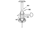
示された例のハウジング104は、患者−ユーザにまたは患者−ユーザから流体媒質を運ぶためにその中で患者−ユーザに中空針またはカニューレを挿入することができる導入部位構造を含むセクション105を含む。他の実施形態では、導入部位の代わりに、または導入部位に加えて、ハウジング104が、流体媒質を運び、流体媒質を含み、かつ/または流体媒質を処理する他の適当な任意の構造を含むことができ、ハウジング104を、該他の適当な任意の構造の部分とすることができ、あるいは、ハウジング104を、該他の適当な任意の構造に動作可能に接続することができる。
The illustrated
第2の部材103もハウジング108を含み、示された実施形態では、ハウジング108が、注入媒質を収容するリザーバのハウジングである。第2の部材103は、ベース106に接続するように構成された別のハウジング部材109の内部に保持することができ、またはハウジング部材109によって覆うことができる。別のハウジング109は、適当な任意の接続構造によって第1の部材102のベース106に接続することができる。特定の実施形態では、適当な接続構造を提供するため、ハウジング109とベース106のうちのどちらか一方が、ハウジング109とベース106のうちの残りの一方の対応する1つ以上の爪、突起および/または窪みとかみ合い、受け入れる、1つ以上の可撓性の爪、突起および/または窪みを含むことができる。あるいはまたは加えて、接続構造が、接着剤または他の適当な接続手段を含むことができる。
The
他の実施形態では、ハウジング108を、センサ構成要素を含むセンサハウジングとする(またはセンサ構成要素を含むセンサハウジングに接続する)ことができる。他の実施形態では、ハウジング108が、流体媒質を運び、流体媒質を含み、かつ/または流体媒質を処理する他の適当な任意の構造を含むことができ、ハウジング108を、該他の適当な任意の構造の部分とすることができ、あるいは、ハウジング108を、該他の適当な任意の構造に動作可能に接続することができる。ハウジング108は、限定はされないが、プラスチック、金属、セラミック、複合材料などを含む、適当に剛性のある任意の材料で形成することができる。
In other embodiments, the
ハウジング104は受入構造110を有し、または受入構造110に接続される。受入構造は、ハウジング内に、受入構造内のチャンバ114へ通じる開口112を有する。示された実施形態では、受入構造110が、導入部位を含むハウジングのセクションに隣接したハウジング104の一部分である。他の実施形態では、受入構造110が、ハウジング104に接続された別のハウジングを含むことができる。
The
受入構造110は、チャンバ114内に位置する第1の隔壁116を含み、隔壁116は、チャンバ114内で、開口112に近づく方向と開口112から離れる方向に移動することができる。受入構造110はさらに、隔壁116に、開口112に向かう向きの付勢力(付勢力)を加える付勢機構118を含む。付勢機構118は、開口112の方に隔壁116を押すことができる。開口112を通して隔壁116がチャンバ114から押し出されることを妨げるため、開口112に隣接する環状突起(あるいは適当な形状を有しまたは適当な位置に配置された1つ以上の突起)120を提供することができる。隔壁116は、付勢機構118によって隔壁116が開口112に押し付けられたときに開口112から少なくとも部分的に露出する前面116aを有する。隔壁116は、チャンバ114の内部に面した後面116bを有する。隔壁116は、針124によって突き通すことができる、限定はされないが、天然または合成ゴム材料、シリコーンなどの適当な任意の材料で形成することができる。特定の実施形態では、隔壁116を、針が隔壁を突き抜け、続いて隔壁116から引き抜かれたときに隔壁116自体を密封することができる自己密封材料で形成することができる。
The receiving
示された実施形態では、付勢機構118は、チャンバ114内に位置するコイルばねであり、このコイルばねは、隔壁116の開口112に面した面と反対側の面に接する。他の実施形態では、限定はされないが、他のタイプのばね、チャンバ114内の加圧流体、隔壁116から延び、自然の、すなわち本来備わるばね力を有する折り畳み可能なスカート構造122、他の化学薬品または物質と接触すると、あるいは熱、レーザ、他の放射源などのエネルギー源からエネルギーが加えられると膨張する化学薬品または物質などを含む、開口112に向かって隔壁116を付勢する他の適当な手段によって、付勢機構118を提供することができる。
In the illustrated embodiment, the
チャンバ114内に、尖端124aを隔壁116の後面116bの方に向けて、中空針124が支持される。示された実施形態では、中空針124が、コイルばね付勢機構118の内側に支持され、その長手軸の方向が、コイルばね付勢機構118の長手軸の方向に対して概ね平行に延びる。中空針124は、受入構造内に位置する支持構造126によって支持することができる。示された実施形態では、支持構造126が、開口112が位置するチャンバ114の端に関してチャンバ114の反対端に位置する、受入構造110のハウジングと一体の壁である。しかしながら、他の実施形態では、支持構造126を、受入構造110のハウジングに対して概ね固定され、受入構造110のハウジングに概ね固定された関係に針124を支持することができる適当な任意の構造とすることができる。
The
中空針124は、限定はされないが、金属、プラスチック、セラミックなどを含む適当な剛性のある任意の材料で形成することができ、針の長さ方向に延びる中空チャネルを有する。針124の中空チャネルは、針の尖端124aのところが開いており、さらに、限定はされないが、尖端124aとは反対側の針端など、針の長さ方向において他の位置124bにおいても開いている。針124の中空チャネルは、針の尖端124aと針の開口124bとの間の流体が流通可能な経路を提供する。示された実施形態では、中空針124の開口124bが、後述する針導入構造内のマニホルド(manifold)128に流体が流通可能な状態で接続される。
The
第2の部材103のハウジング108は、中空内側チャンバ132と中空内側チャンバへの開口134とを有する接続部分130を含む。開口134を密封するため、ハウジング108によって第2の隔壁136が支持される。隔壁136は、ハウジング108に固定された関係で、例えばハウジング108内のチャンバ132の一端に支持することができる。
The
ハウジング108の接続部分130は、第1の部材102と第2の部材103とが互いに接続されたときに第1の部材102の受入構造110の開口112の内側に少なくとも部分的にはまる適当な形状およびサイズを有する。図1および2には、接続されていない分離された関係にある第1および第2の部材102,103が示されており、この状態でハウジング108の接続部分130は受入構造110の開口112の外側にある。第1および第2の部材102,103を移動させて1つにし、ハウジング104の開口112に接続部分130を挿入することによって、接続部分130の端面138が隔壁116に押し付けられ、接続部分130の端面138が、隔壁116を、ハウジング108に対して、付勢機構118の力に逆らって、チャンバ114の内部に向かって移動させる。隔壁116がハウジング108の内部に向かって移動すると、針124の尖端124aが隔壁116に突き刺さる。さらに第1の部材102と第2の部材103を互いに相対移動させると、針124の尖端124aが第1の部材102の隔壁116を突き抜け、次いで第2の部材103の隔壁136に突き刺さり、隔壁136を突き抜ける。
The connecting
上述のとおりに、第1の部材102と第2の部材103を、図3に示されているように一緒にすると、接続部分130の少なくとも一部分が、受入構造110のハウジングの内側に延びる。さらに、針124が、第1の部材102の隔壁116および第2の部材103の隔壁136を貫通して、接続部分130の内部チャンバ132とマニホルド128(または針124の開口124bのところの他の構造)との間に流体が流通する経路を形成する。受入構造110および接続部分130は、第1の部材102と第2の部材103が図3に示されているように一緒にされたときに例えばスナップ(snap)接続または摩擦接続を提供する対合コネクタを備えることができる。一実施形態では、対合コネクタが、接続部分130が受入構造110内へ適当な距離だけ延びたときに互いにスナップばめ方式でかみ合うように配置された、受入構造110と接続部分130のうちのいずれか一方の表面の突起と、受入構造110と接続部分130のうちの残りの一方の溝または窪みとを含むことができる。
As described above, when the
前述のとおり、示された実施形態では、針124の開口124bが、導入部位構造のマニホルド128に流体が流通可能な状態で接続される。導入部位構造は、ハウジング104(図1)のセクション105内に提供され、ハウジング104およびベース106を貫通して延びるチャネル140を含む。チャネル140は、(図2に示された向きに関して)ベース106の下面に開端140aを有する。チャネル140は、(図2に示された向きに関して)ハウジング104のセクション105の上面に別の開端140bを有する。マニホルド128は、チャネル140の長さに沿って位置し、チャネル140と流体が流通可能にする。したがって、中空針124は、マニホルド128を介してチャネル140の内部と流体流通可能な状態で配置される。チャネル140は、チャネル140の他の部分よりも大きな半径寸法と、後述するカニューレヘッドを受け入れる適当な形状およびサイズとを有するチャネルセクション142を含む。
As described above, in the illustrated embodiment, the
チャネル140の開端140bに隣接して針挿入装置144を配置することができ、針挿入装置144は、後述するように、チャネルの開端140bの中および少なくとも部分的にチャネル140の中に、針および/またはカニューレを選択的に延入させるように配置することができる。針挿入装置144は、第1の部材102のハウジング104のセクション105と一体であるように構成することができ、または他の方式で第1の部材102のハウジング104のセクション105に固定されるように構成することができる。あるいは、針挿入装置144を(ハウジング104とは)別個の装置とすることができ、選択的に、(図2に示されているようにチャネル140と整列させて)ハウジング104のセクション105に接続し、ハウジング104のセクション105から分離することができる。
A
針挿入装置144が、ハウジングセクション105に接続し、ハウジングセクション105から分離される別個の構造である実施形態では、針挿入装置144とハウジングセクション105の間の手動で解放可能な接続を提供するために、これらの構成要素上に適当な接続構造を提供することができる。このような接続構造は、限定はされないが、針挿入装置144とハウジングセクション105のうちのいずれか一方の表面のねじが切られた延長部分と、このねじが切られた延長部分をねじ式のかみ合いで受け入れる、針挿入装置144とハウジングセクション105のうちの残りの一方の表面のねじが切られた対応する受入部とを含むことができる。他の実施形態では、限定はされないが、針挿入装置144とハウジングセクション105のうちのいずれか一方の表面の可撓性の爪または延長部分、およびハウジングセクション105と針挿入装置144のうちの残りの一方の表面の対応する開口部、ストップ面などを含む、他の適当な接続構造を使用することができる。
In embodiments where the
図2には、ハウジングセクション105に接続され、針146およびカニューレ148が格納された状態にある針挿入装置144が示されている。針挿入装置144は、針146およびカニューレ148を、格納状態(図2に示されている)から延出状態(図示せず)に選択的に移動させるように動作する。延出状態では、針146の尖端およびカニューレ148の長さ方向において少なくともその一部分が、チャネル140の開口140aから延出するように、針およびカニューレが、チャネル140の開口140bを通過して、チャネル140を少なくとも部分的に貫通して延出される。針挿入装置に対する適当な構造のさまざまな例が、その全体を本願に引用して援用する、本発明の譲受人に譲渡された2006年12月26日出願の「Infusion Medium Delivery system,Device And Method With Needle Inserter And Needle Inserter Device And Method」という名称の米国特許出願第11/645,435号(代理人整理番号047711.0406)に記載されている。針挿入装置の適当な構造の他の例は本明細書に記載されている。
FIG. 2 shows the
カニューレ148は、その長手方向に沿って延び、一端(針146の尖端に隣接したカニューレ端)が開いた中空中心チャネルを有する。カニューレ148の他端は、カニューレのシャフト部分よりも大きな半径寸法を有するヘッド150を有する。カニューレヘッド150は、針挿入装置144によって針146およびカニューレ148が延出状態まで移動したときにチャネル140のセクション142の中にはまる適当な形状およびサイズを有する。特定の実施形態では、針挿入装置144によって針146およびカニューレ148が延出状態まで移動したときにセクション105内のそのままの位置にカニューレ148をロックし、または保持する摩擦ばめ、スナップばめなどを提供するため、カニューレヘッド150が、セクション105のチャネルセクション142の対応する1つ以上の窪みおよび/または突起とかみ合う1つ以上の突起および/または窪みを含むことができる。他の実施形態では、針挿入装置144によって針146およびカニューレ148が延出状態まで移動したときにセクション105内のそのままの位置にカニューレ148を保持する適当な保持機能を提供するために、突起と窪みとをかみ合わせる代わりに、または突起と窪みとをかみ合わせることに加えて、限定はされないが、摩擦ばめ構造、スナップばめなどを含む、他の機械的構造を使用することができる。
カニューレ148はさらに、カニューレ148の中心長手方向チャネルと流体が流通可能な状態で提供された接続チャネル152を有する。接続チャネル152は、針挿入装置144によって針146およびカニューレ148が延出状態まで移動したときにチャネル152がマニホルド128と(マニホルド128の内部と流体が流通可能な状態で)整列する、カニューレ148の長手方向に沿ったある位置に提供される。このようにすると、カニューレ148が延出状態まで移動したときに、カニューレ148の中心長手方向チャネルが、マニホルド128および接続チャネル152を介して、中空針124と流体が流通可能な状態で配置される。
The
したがって、動作時、第1の部材102(例えば受入部110とセクション105とを有するハウジング104を含むことができる)は、第2の部材103の接続部分130を第1の部材102の受入部110に挿入することによって、第2の部材103(例えば流体リザーバハウジング108を含むことができる)と結合される。第1の部材102と第2の部材103とを結合すると、第2の部材103の内部と第1の部材102の導入部位構造とが流体が流通可能になる。
Thus, during operation, (which may include a
さらに、第1の部材102のハウジング104のセクション105に針挿入装置144が結合される(またはハウジング104のセクション105と一体の単一構造の一部として針挿入装置144が提供される)。第1の部材102のベース106を患者−ユーザの皮膚(の適当な導入位置)に、例えば、限定はされないが、2006年12月26日に出願された「Infusion Medium Delivery system,Device And Method With Needle Inserter And Needle Inserter Device And Method」という名称の米国特許出願第11/645,435号(代理人整理番号047711.0406)に記載された接着剤および/または本明細書に記載された接着剤で固定することができる。あるいはまたは加えて、限定はされないが絆創膏などを含む他の適当な構造によって、ベース106を患者−ユーザに固定することもできる。
Further, a
患者−ユーザの皮膚の適当な導入位置にベース106が適当に固定された後、挿入装置144を作動させて、針146およびカニューレ148を格納状態(図2に示された)から延出状態に移動させることができる。延出状態では、針146およびカニューレ148が、ベース106に隣接した患者−ユーザの皮膚に突き刺さる。カニューレヘッド150とチャネルセクション142を前述のとおりにかみ合わせることによって、カニューレ148をその延出状態にロックすることができる。カニューレ148が延出状態にロックされると、(例えば針挿入装置144の自動動作によって、および/または針挿入装置144をセクション105から手で取り外すことによって)針146を格納することができる。針146が取り外された後、カニューレ148はセクション105によってその場に保持され、カニューレ148の一部が患者−ユーザの体内に延び、カニューレ148が中空針124に流体が流通可能な状態で接続される。前述のとおりに第1の部材102と第2の部材103が一緒に接続された場合、中空針124およびマニホルド128を介して、リザーバ108からカニューレ148への流体流通可能な接続が提供される。
After the
接続順序(例えば針挿入装置144をハウジング104のセクション105に接続し、ハウジング104のレセプタクル110をリザーバハウジング108の接続部分130に接続し、第1の部材102のベース106を患者−ユーザの皮膚に接続する順序)は、実施形態によって異なることがある。一実施形態では、患者−ユーザが、ベース106およびハウジング104(セクション105を含む)を含む第1の部材102を、針挿入装置144に予め接続された状態で受け取ることができる。このようにすると、(予め接続された状態で例えば製造施設または組立施設からユーザに供給されるため、)患者−ユーザは、針挿入装置144をハウジング104に接続する必要がない。この実施形態では、患者−ユーザ(または医師)が、第1の部材102のベース106を患者−ユーザの皮膚の適当な導入位置に固定することができる。患者−ユーザの皮膚にベース106を固定した後、患者−ユーザ(または医師)は、針挿入装置144を作動させて、針146およびカニューレ148が延出状態に移動し、患者−ユーザの皮膚に突き刺さるようにすることができる。
Connection sequence (eg, the
針挿入装置144を作動させた後、セクション105から針挿入装置144を取り外し、患者−ユーザの体内に部分的に延ばされたカニューレ148を、セクション105内のそのままの位置に残すことができる。第1の部材102のベース106が患者−ユーザの皮膚に固定され、カニューレ148が、患者−ユーザの体内に少なくとも部分的に挿入され、中空針124と流体が流通可能な状態で配置された後、第2の部材103を第1の部材102に接続することができる。具体的には、第2の部材103のハウジング108の接続部分130を第1の部材102のハウジング104の受入部110に挿入して、ハウジング108の内部と中空針124の間、したがってハウジング108の内部とカニューレ148の間の流体が流通可能な接続を提供することができる。したがって、リザーバから患者−ユーザに流体を送達するために(または患者−ユーザからリザーバに流体を運ぶために)、(リザーバハウジングとすることができる)ハウジング108の内部を、患者−ユーザの体内に延ばされたカニューレ148に、流体が流通可能な状態で結合することができる。
After actuation of the
上記の実施形態の接続順序は、第2の部材103を第1の部材102に接続する前に第1の部材102のベース106を患者−ユーザに固定することを含むが、他の実施形態では、(前述のとおりに)患者−ユーザの皮膚に第1の部材102のベース106を固定する前に、第2の部材103を第1の部材102に接続することができる。このような他の実施形態では、第1の部材102と第2の部材103を互いに接続し、その後に、第1の部材102と第2の部材103のうちの一方または両方を患者−ユーザの皮膚に接着することによって、接続された部材102および103を患者−ユーザに固定することができる。さらに、上記の実施形態の接続順序は、第2の部材103を第1の部材102に接続する前に針挿入装置を作動させることを含むが、他の実施形態では、(前述のとおりに)針挿入装置144を作動させる前に、第2の部材103を第1の部材102に接続することができる。
The connection sequence of the above embodiment includes securing the
図1および2に示された実施形態では、受入部110が第1の部材102にあり、接続部分130が第2の部材103にある。しかしながら、他の実施形態では、受入部110を第2の部材103に配置する(例えば受入部110をリザーバ108のハウジングに配置し、またはリザーバ108のハウジングに関連づける)ことができ、接続部分130を第1の部材102に配置する(例えば接続部分130を導入部位構造を含むハウジングに配置し、または導入部位構造を含むハウジングに関連づける)ことができる。さらに、図1および2に示された実施形態では、(図2の向きに関して)ベース106の上を向いた表面の平面に実質的に平行な方向に第2の部材103の接続部分130を挿入することができるように、受入部110が配置される。図2の向きでは、この挿入方向が、第1の部材102と第2の部材103の間の水平方向の相対運動として示されている。しかしながら、他の実施形態では、限定はされないが、挿入方向(第1部材102と第2の部材103の相対運動)を(図2の向きにおいて)ベース106の上を向いた表面の平面に対して実質的に垂直にすることを可能にする向きを含む、他の適当な向きに受入部110を配置することができる。他の実施形態では、(図2の向きにおいて)ベース106の上を向いた表面の平面をある角度で横切る他の適当な任意の挿入方向を可能にするように、受入部110を配置することができる。
In the embodiment shown in FIGS. 1 and 2, the receiving
図7〜10に示された例示的な配置は、(図2の向きにおいて)ベース106の上を向いた表面の平面に対して実質的に垂直な挿入方向(第1の部材102と第2の部材103の相対運動)を提供する。図7〜10の構成要素は、同様の構造および機能の構成要素に対して図1〜6で使用された参照符号と同じ参照符号によって識別される。図7および8には、カニューレ148を延出位置へ移動させるように針挿入装置を動作させた後の状態の、ハウジング104内の導入部位構造が示されている。
The exemplary arrangement shown in FIGS. 7-10 has an insertion direction (
図9および10は、ハウジング104に針挿入装置144が取り付けられた(図7および8の実施形態の)第1の部材102のベース106を示す。図9および10の針挿入装置144は、限定はされないが、針挿入装置144をハウジング104に接続する、図1〜6の実施形態に関して上で論じた方式などの適当な任意の方式でベース106に固定することができるハウジング161を含む。図10に示されているように、ハウジング161は、長手方向Lを有する内部チャンバと、ハウジング161内に位置するプランジャ162とを含み、プランジャ162は、長手方向Lに沿って、(図10では実線で示された)格納位置から(図10では破線で示された位置Eにプランジャ162が移動した)延出位置へ移動することができる。延出位置Eに向かってプランジャ162を押すため、限定はされないがハウジング161内に配置されたコイルばねなどの付勢部材164が、プランジャが格納位置にあるときにプランジャに付勢力を加える。付勢部材164の付勢力に逆らってプランジャ162をその格納状態に選択的に保持するため、および付勢部材164の力を受けて長手方向Lに移動するように、ユーザがプランジャ162を選択的に解放することを可能にするために、限定はされないが、ハウジング161に接続され、またはハウジング161を貫通して延び、プランジャ162(またはプランジャを保持する他の構造)と解放可能な方式でかみ合う、手で移動させることができる突起、レバーまたはスライダなどのロック機構(図示せず)を提供することができる。
FIGS. 9 and 10 show the
ハウジング161内に、プランジャ162の移動によって長手方向Lに移動するインサート構造体166が配置される。インサート構造体166は、(図1〜6の実施形態に関して前に説明した隔壁116と同様の)隔壁167を保持するカップ形のボディ168を含む。(前述のカニューレ148と同様の)中空カニューレ148は、隔壁116に隣接して(または隔壁116内に少なくとも部分的に)配置された尖端を有することができる1つの開端148aを有する。中空カニューレ148は、カップ形のボディ168を貫通して延び、第2の開端148bを有する。カップ形部材168の移動と一緒に移動するように、中空カニューレ148をカップ形部材168に固定することができる。プランジャ162には針170が固定され、針170は、プランジャ162が図10に示された格納位置にあるときに隔壁167およびカニューレ148を貫通して延びる。
In the
動作時、患者−ユーザ(または医師)は、(図1〜6のベース106に関して前に説明したのと同様に)患者−ユーザの皮膚にベース106を固定することができる。患者−ユーザの皮膚にベース106が固定された後、患者−ユーザ(または医師)は、針挿入装置144を作動させて、プランジャ162が、その格納状態からその延出状態へ移動し、このような移動の結果として、インサート構造体166がハウジング104の内部へ移動するようにすることができる。インサート構造体166がハウジング104内へ移動した後、適当な任意の接続構造によって、インサート構造体166はハウジング104に接続することができる。特定の実施形態では、適当な接続構造を提供するために、インサート構造体166のカップ形部材168とハウジング104のうちのいずれか一方が、ハウジング104とインサート構造体166のうちの残りの一方の表面の対応する1つ以上の爪、突起および/または窪みとかみ合い、受け取る1つ以上の可撓性の爪、突起および/または窪みを含むことができる。あるいはまたは加えて、接続構造は、接着剤または他の適当な接続手段を含むことができる。図7は、延出位置にある、ハウジング104内にロックされた(例えば針挿入装置144によって挿入され、ハウジング104から針挿入装置144が取り外された後の)インサート構造体166を示す。
In operation, the patient-user (or physician) can secure the base 106 to the patient-user's skin (as described above with respect to the
特定の実施形態では、(図10に示された)格納状態から延出状態へプランジャ162およびインサート構造体166を移動させたときに、針挿入装置144のハウジング161をベース106から自動的に解放することができる。例えば、針挿入装置144のハウジング161を、本明細書で説明したように動作する十分な剛性を有し、同時に、インサート構造166が延出状態に移動したときに(少なくともハウジング104に接続する針挿入装置144の部分において)ハウジング104から離れる方向に曲がり、ハウジング104から解放される適当な可撓性を有する材料で形成することができる。
In certain embodiments, the
図10に示されているように、ハウジング161の内面の部分172は、インサート構造体166およびプランジャ162が延出状態に向かって移動するときにインサート構造体166および/またはプランジャ162の外周面と係合する、(ハウジング161、カニューレ148および針170の軸方向に対して)傾斜した、くさび形のまたは斜めの断面形状を含むことができる。ハウジング161の内面の斜めの、傾斜した、またはくさび形の部分172と係合することによって、プランジャ162および/またはインサート構造体166は、プランジャ162およびインサート構造体166が延出位置へ移動するときに、ハウジング161の壁(1つ以上)を外側に曲げる。ハウジング161の壁(1つ以上)が外側により曲がるようにするために、ハウジング161に、1つ以上のスロット、溝など174を形成することができる。ハウジング161の内面とハウジング104の外面のうちのいずれか一方に、プランジャ162およびインサート構造166が図10に示された格納状態にあるときにハウジング104とハウジング161のうちの残りの一方の対応する1つ以上の窪み178および/または突起とかみ合う1つ以上の突起176および/または窪みを提供することができる。
As shown in FIG. 10, the
突起176および窪み178は、かみ合わされたときに、針挿入装置144のハウジング161をハウジング104にロックする。この1つ以上の突起および/または窪みは、プランジャ162およびインサート構造166が延出状態に移動することによってハウジング161の壁(1つ以上)が外側に曲げられたときに、互いの相手から外れる。その結果、プランジャ162およびインサート構造体166が延出状態に移動したときに、針挿入装置144のハウジング161をハウジング104から自動的に分離し、解放することができる。(図10に示された)格納状態から(インサート構造166がハウジング104内にロックされ、針挿入装置144のハウジング161がハウジング104から解放される)延出状態へプランジャ162およびインサート構造166が移動した後、付勢部材164(または第2の付勢部材(図示せず))は、針170に対して、格納位置に向かって針170を移動させ、したがってカニューレ148から針170を引き抜くように作用することができる。例えば、格納状態から延出状態へ移動した後のコイルばねの戻り運動は、カニューレ148から針170を引き抜く十分な力を提供することができる。
The
インサート構造体166がハウジング104内にロックされ、針挿入装置144がハウジング104から取り外された後、図1〜6の実施形態において第1の部材102と第2の部材103が接続可能である方式と同様の方式で、カニューレ148を、(限定はされないがリザーバハウジング108などの)第2の部材の接続部分130と、流体が流通可能な状態で接続することができる。より具体的には、ハウジング104は、(図1〜6に関して前に説明した受入部110と同様の)受入部を形成し、(図1〜6の第1の隔壁116と同様の)第1の隔壁として機能する隔壁116を含む。
Method in which the
図1〜6の実施形態と同様に、図7の接続部分130も第2の隔壁136を含む。具体的には、リザーバハウジング108の内部をカニューレ148と流体が流通可能な状態で接続するために、ハウジング104によって形成された受入部に接続部分130を挿入することができる。図7のカニューレ148は、第1の隔壁116に隣接した尖端148aを含むことができる。接続部分130がハウジング104に挿入されると、接続部分は、カニューレ148の尖端148aに対して第1の隔壁116を押し、カニューレ148の尖端148aが第1の隔壁116に突き刺さるようにする。接続部分130をハウジング104内にさらに挿入すると、カニューレ148の尖端148aは接続部分130の第2の隔壁136を突き抜けて、カニューレ148を介した、接続部分130からの流れ経路または接続部分130への流れ経路を形成する。
Similar to the embodiment of FIGS. 1-6, the connecting
図11〜13の実施形態:
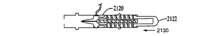
図11〜13を参照して、リザーバプランジャに駆動機構を接続する構造の他の実施形態を説明する。図11では、リザーバ200が、前述のとおり、流体媒質を収容する中空内部を有するハウジング202を有する。ハウジング202内にはプランジャヘッド204が位置し、プランジャヘッド204は、リザーバ200の内部容積を拡張しまたは収縮させるためリザーバ200の軸方向Aに沿って移動可能である。プランジャヘッド204から、ハウジング202の外側に一対のロッド206および207が延びる。ロッド206および207は、U字形のナット208とプランジャ204との間の固定された接続を提供するように機能する。ロッド206および207によってU字形ナット208を支持することができる。あるいはまたは加えて、ガイドレール209によってU字形ナット208を、リザーバ200の軸方向Aに沿って移動するように支持することもできる。
Embodiments of FIGS. 11-13:
With reference to FIGS. 11-13, other embodiment of the structure which connects a drive mechanism to a reservoir plunger is described. In FIG. 11, the
図12では、U字形ナット208が、梁208cによって接続され、それらの間にチャネル210を形成する一対のアーム208aおよび208bを有する。図11では、リザーバ200が、U字形ナット208のチャネル210の開いた側をベース106から遠い方に向けてベース106上に支持されるように構成される。恒久性ハウジング部分212は、リザーバ200を覆ってベース106に固定されるように構成される。恒久性ハウジング部分212は、前述の他の構成要素とともに、前述の駆動装置と動作可能に係合するねじが切られた駆動軸214を内包する。図12では、ベース106に接続するために恒久性ハウジング部分212がベース106上に配置されたときに、駆動軸214がチャネル210の中にはまり、駆動軸214がアーム208aおよび208bと係合する恒久性ハウジング部分212内のある位置に、駆動軸214が配置される。U字形ナット208のチャネル210は、組立および製作公差の容易さのため、図12の方向Aに沿った駆動軸214の複数の位置のうちの任意の1つの位置において駆動軸214がアーム208aおよび208bと係合することを可能にする十分な深さを有することができる。特定の実施形態では、恒久性ハウジング部分212がベース106に接続するベース106上の位置に恒久性ハウジング部分212を配置すると、駆動軸214とU字形ナット208のチャネル210との整列も達成され、その結果、駆動軸214をU字形ナット208に動作可能に接続するためのこれらの構成要素の追加の操作が不要となる。
In FIG. 12, a
図12では、U字形ナット208のアーム208aおよび208bを軸方向Aに沿って互いにずらすことができ、駆動軸214上のねじ山と係合するように、アーム208aおよび208bを構成することができる。U字形ナット208と係合している間に駆動軸214を回転させると、それによりU字形ナット208が軸方向Aに沿って移動する。ロッド206と207の一方または両方に対してU字形ナット208を接触させ、かつ/または接続することによって、U字形ナット208の軸方向Aに沿った移動が、ロッド206および207の軸方向Aに沿った移動、したがってプランジャヘッド204の軸方向Aに沿った移動に変換される。したがって、駆動軸214をU字形ナット208と係合させると、駆動軸214を選択的に駆動することによって、リザーバプランジャ204の移動を選択的に実行し、制御することができる。
In FIG. 12, the
図14〜21の実施形態:
針インサータ装置712の他の実施形態が、本願に引用して援用する(本発明の譲受人に譲渡された)「Infusion Medium Delivery system Device And Method With Needle Inserter And Needle Inserter Device And Method」という名称の米国特許出願第11/645,435号の図24〜25に関して記載されている。本明細書では、上に引用した特許出願に記載された針インサータ装置712の他の態様および変形を、図14〜21を参照して説明する。図14〜21に示された構造の諸特徴および構成要素は、上で引用した米国特許出願第11/645,435号において同じまたは同様の特徴に対して使用された参照符号に対応する参照符号によって識別される。本発明の一実施形態に基づく針挿入装置を図14〜16を参照して説明し、本発明の他の実施形態に基づく針挿入装置を図17〜21を参照して説明する。
Embodiments of FIGS. 14-21:
Another embodiment of the
図14では、針インサータ装置712が開始状態にある。図15では、針インサータ装置712が延出状態にある。(図14に示された)針インサータ装置712はハウジング部分744を含む。ハウジング部分744は、限定はされないが、上で引用した米国特許出願第11/645,435号に記載されたリザーバ、駆動装置、連結構造、制御電子回路などのシステムの他の構成要素を含む別のハウジングの部分とすることができ、または該別のハウジングに含めることができ、または該別のハウジングに接続することができる。特定の実施形態では、ハウジング部分744を、上で引用した米国特許出願第11/645,435号に記載された恒久性ハウジング部分に接続する使い捨てハウジング部分の部分とすることができ、または該使い捨てハウジング部分に含めることができ、または該使い捨てハウジング部分に接続することができる。
In FIG. 14, the
他の実施形態では、針インサータ装置712を、上で引用した米国特許出願第11/645,435号に記載された恒久性ハウジング部分、または前記使い捨てハウジング部分もしくは前記恒久性ハウジング部分に接続された導入部位モジュールの部分とすることができ、該恒久性ハウジング部分または導入部位モジュール内に配置することができ、あるいは該恒久性ハウジング部分または導入部位モジュール接続することができる。あるいは、針インサータ装置712を、対象に針を挿入することによって動作する他のシステムに含めることもできる。ハウジング部分744は、概ね円筒形または円板形の堅いボディを含むことができ、ボディは、概ね円筒形の中空内部と、ボディの概ね円筒形の形状の軸A1に沿った長手方向寸法とを有する。ハウジング部分744の内面は、(図14に示された向きに関して)ハウジング部分744の頂部に近い、頂部から離隔したある位置から始まり、ハウジング部分744の内周壁に沿って、ハウジング部分744のベースの近くのある位置まで延びる螺旋溝746を有する。螺旋溝746のベース端に、別の直線溝(図14には示されておらず、上で引用した米国特許出願第11/645,435号の図24の748に示されている)が提供され、この直線溝は、(図14に示された向きに関して)ハウジング部分744の頂端に向かって延びる。この直線溝は、螺旋溝746のベース端を螺旋溝746の頂端に接続し、螺旋溝746の頂端よりも上に短い距離だけ延びる。
In other embodiments, the
ハウジング部分744の内部にカム部材750が位置し、カム部材750は、螺旋溝746の中に延びる突き出た外周縁751を有する。ハウジング部分744は、一端(図14の向きにおける頂端)に開口752を含み、開口752から、手動または自動の力によってカム部材750を操作することができる。開口752を通してカム部材750の表面を露出させることができる。カム部材750の露出した表面は、カム部材750が図14に示された格納位置にあるときに開口752内に延び、または開口752を部分的に通り抜ける凸形の形状を含むことができる。ハウジン部分グ744はさらに、ハウジング部分744のベースを貫通する針開口753を含み、後述するように、針開口753を通して針およびカニューレを延出させることができる。
A
カム部材750は、コイル状ねじりばね754によってハウジング部分744の内部に支持される。ばね754は、カム部材750とハウジング部分744のベースの間に延び、ハウジング部分744のベース部分に固定された(またはハウジング部分744のベース部分に隣接した)一端と、カム部材750に固定された他端とを有する。
図14の開始状態すなわち格納状態では、ばね754がばねの巻付け方向の力をカム部材750に加えるように、ばね754が、その自然の巻かれた状態に逆らって部分的に巻き戻されている。しかしながら、カム部材750の突き出た縁751は、(上で引用した米国特許出願第11/645,435号の図24に示されているように)螺旋溝746の上端から外れた直線溝のあるセクション内に位置するため、ばね754は、ばね754の自然の巻付け力に逆らって部分的に巻き戻された状態に保持される。
The start state, that stores the state of FIG. 14, the winding direction of the force field I 754 spring to apply to the
図14に示された格納状態から、ハウジング部分744の開口752を通してカム部材750に(図14の向きに関して下向きの力などの)手動または自動の力を加えて、カムの縁751が、直線溝(上で引用した米国特許出願第11/645,435号の溝748)に沿って、ハウジング部分744のベースに向かって移動して、(図面の向きに関して)螺旋溝746の頂端と整列するまで、矢印755の方向に沿って軸方向A1に移動するようにカム部材を押し、ばねの自然の圧縮力に逆らってばね754を部分的に圧縮する。カムの縁751が螺旋溝746と整列すると、ばね754は、張力が加わっていないその自然の巻付け状態に向かって巻かれるため、ばね754の自然の巻付け力によって、カム部材750は回転し、ハウジング部分744のベースに向かって移動する。その間、カム縁751は螺旋溝746をたどる。しかしながら、カム部材750がハウジング部分744のベースに向かって移動すると、カム部材750は、ばね754を、軸線A1方向の自然の長手方向寸法を更に縮めるよう圧縮する。
From the retracted state shown in FIG. 14, a manual or automatic force (such as a downward force with respect to the orientation of FIG. 14) is applied to the
ハウジング部分744のベースに向かってカム部材750が移動すると、ハウジング部分744のベースの開口754を通って針758が(図15に示された)延出位置に移動する。針758は、カム部材750および針758の(図14に示された)開始位置ないし格納位置からカム部材750および針758の(図15に示された)延出位置までカム部材と一緒に移動するように、ベースに面したカム部材の表面に固定される。
When the
針758の尖端に隣接した針758の軸上にカニューレ759を支持することができる。カニューレ759の一端を漏斗状に開いた形にし、または移動可能なキャリッジ782に固定されたヘッド部分780に取り付けることができる。キャリッジ782は、ハウジング744内の、移動可能なカム部材750とハウジング部分744のベースおよび針開口753との間に位置する。キャリッジ782は、カム部材750の軸線方向A1の移動とともに軸線方向A1に移動するようにハウジング部分744内に支持される。
キャリッジ782は、限定はされないが、プラスチック、金属、セラミック、複合材料などの適当な剛性のある任意の材料で形成されたボディを含むことができる。キャリッジ782のボディは、その中を針758が延びる中心通路を含むことができる。キャリッジ782のボディ内に、隔壁状のシール部材784を保持することができる。針758は、シール部材784を貫通して延び、シール部材784内でスライドすることができ、一方、シール部材784は、針758の外周に沿ったシールを形成する。キャリッジ782のボディ内でのシール部材784の保持を助け、シール部材784に追加の剛性を提供するため、シール部材784に隣接させて、限定はされないが全体が剛体の環状円板形のワッシャ構造785などの保持構造を配置することができ、この保持構造はさらに、その中を針758が延び、移動することができる中心通路を提供する。
The
キャリッジ782は、(図14に示された)キャリッジ782の開始状態から(図15に示された)キャリッジ782の延出状態へキャリッジ782を移動させるために、(やはり図14に示された)カム部材750の開始状態から(やはり図15に示された)カム部材750の延出状態へカム部材750を移動させたときに、カム部材750と係合する(または少なくともカム部材750から力を受け取る)表面782a(図14に示された向きにおいて上面)を有する。ハウジング部分744内に、例えばハウジング部分744と一体の部分として、あるいはハウジング744のベースに固定された別個の構造として、ガイド構造786を提供することができる。ガイド構造786は、(図14に示された)キャリッジの開始状態から(図15に示された)キャリッジの延出状態へキャリッジを移動させたときにキャリッジ782の1つ以上の表面と係合する1つ以上の壁、レールまたは他の適当な構造を含むことができる。一実施形態では、図14に示されているように、ガイド構造786が、概ね中空の円筒形の管形構造を含むことができ、キャリッジ782から延びる対応する1つ以上の突起788を受け入れるために、ガイド構造786のこの円筒形の壁に沿って、1つ以上のスロットまたは溝が軸線方向A1に延びる。突起(1つ以上)788は、キャリッジ782を軸線方向A1に移動させたときにガイド構造786の概ね円筒形の壁の軸方向のスロットまたは溝に沿って移動する。
The
(図14に示された)開始状態から延出状態(図15)にキャリッジ782を移動させた後、その延出状態位置にキャリッジ782をロックするように1つ以上のロック機構が動作するある位置に、キャリッジ782を配置することができる。示された実施形態では、1つ以上のロック機構を、1つ以上の可撓性の爪790によって提供することができる。爪790は、ガイド構造786の一部として形成することができ、またはガイド構造786に隣接させることができる。爪790はそれぞれ、軸線方向A1に沿ってハウジング部分744のベースから開口752に向かって延びる可撓性のアーム部分を含む。(図15に示された)その延出状態までキャリッジ782を移動させた後でキャリッジ構造体782が軸線方向A1にさらに移動することを妨げるため、爪790はそれぞれさらに、キャリッジ782と係合するストップ面を有するヘッド790aを含む。示された実施形態では、爪790が、キャリッジ782が(図15に示された)延出状態にあるときにキャリッジ782の表面782aと保持構造785のうちの一方または両方と係合するように配置される。爪790はそれぞれ、開始状態(図14)から延出状態(図15)にキャリッジを移動させたときにキャリッジ782と係合する斜めの表面790bを有することができ、その延出状態に向かってキャリッジが移動する間に、キャリッジ782が爪ヘッド790aを通り越すことを可能にするのに十分なだけ、キャリッジが、爪790を(軸線A1に関して)半径方向外側に押し、撓曲させることを可能にする。
After moving the
(カム部材750をその延出状態へ移動させる作用によって)キャリッジ782をその延出状態に移動させた後、爪790によってキャリッジ782を、ハウジング部分744に対してそのままの位置にロックすることができる。次いで、ばね754の圧縮力をカム部材750に作用させることができ、カム部材750は直線溝(上で引用した米国特許出願第11/645,435号の溝748)をたどって、(図16に示された)その格納状態へ移動することができる。カム部材750がその格納状態へ移動すると、カム部材750は針758を軸線方向A1に移動させ、カニューレ759から針758を少なくとも部分的に引き抜いて、カニューレヘッド780からカニューレ759内への流体が流通する経路を開く。
After the
図16に示されているように、キャリッジ782のボディおよびキャリッジ782に取り付けられた導管792によって、カニューレヘッド780への流体が流通する経路またはカニューレヘッド780からの流体が流通する経路を提供することができる。導管792は、導管792がキャリッジ782に取り付けられたままキャリッジ782が(図14に示された)その開始状態と(図15に示された)その延出状態との間を移動することを可能にする十分な可撓性および/またはたるみを有することができる。導管792は、リザーバ、センサ構造および流体を保持しまたは流体を処理する他の適当な機構(図14〜16には示されていない)のうちの1つ以上の要素まで延び、またはこれらの要素から延びることができ、これらの要素との流体が流通可能な状態を提供することができる。
As shown in Figure 16, the body and guide
あるいは、キャリッジ782が(図15に示された)その延出状態に到達したときに、ハウジング744内に支持された流体が流通する経路または導管と自動的に整列して、リザーバ、センサ構造および流体を保持しまたは流体を処理する他の適当な機構(図14〜16には示されていない)のうちの1つ以上の要素への流体が流通する経路、あるいはこれらの要素からの流体が流通する経路を完成させるように、キャリッジ782のボディ内を通る流体流れ通路(図16では破線で示されている)を配置することができる。リザーバ、センサ構造、あるいは流体を保持しまたは流体を処理する他の機構にカニューレ759を流体が流通可能な状態で接続するために、他の実施形態では、キャリッジ782およびハウジング部分744が、(その全体を本願に引用して援用する上で引用した米国特許出願第11/645,435号の図4〜8の実施形態に関して記載された針50または150および隔壁54または154と同様の)針および隔壁構造を備えることができる。
Alternatively, when the
したがって、ハウジング部分744のベースを導入部位のところに支持することによって、患者−ユーザの皮膚に隣接した位置にハウジング744を配置して、針758が図15の延出位置にあるときに、針758の尖端が患者−ユーザの皮膚に突き刺さり、針シャフトを取り巻くカニューレを、患者−ユーザの皮膚に少なくとも部分的に挿入することを可能にすることができる。
Thus, by supporting the base of the
延出位置(図15)で、キャリッジ782は、ハウジング部分744に対してそのままの位置にロックされる。また、針758およびカニューレ759が図15の延出位置にくると、(溝746の螺旋経路をたどって移動した)カムの突起751が、直線溝(上で引用した米国特許出願第11/645,435号の溝748)と整列する。この位置で、ばね754は、その自然の長手方向の状態を超えて軸線A1の長手方向に延ばされる。したがって、ばね754は、カム部材750に力を加えて、軸線方向A1の矢印755の方向とは反対の方向にカム部材750を移動させる。その間、突起751は図16の格納位置まで直線溝(上で引用した米国特許出願第11/645,435号の溝748)をたどる。
In the extended position (FIG. 15), the
圧縮されていたばね754の力を受けてカム部材750が格納状態に移動すると、針758は、カニューレ759から少なくとも部分的に抜け、キャリッジ782のボディ内の通路を介した導管792からカニューレ759への流体が流通する経路を開く。したがって、患者−ユーザの皮膚にカニューレ759を挿入することができ、カニューレ759を、導管792(および導管792に流体が流通可能な状態で接続されたリザーバ、センサ構造、あるいは流体を保持しまたは流体を処理する他の機構)に流体が流通可能な状態で接続することができる。
When the
前述のとおり、(図14に示された)開始状態から(図15に示された)延出状態へのカム部材750の軸線方向A1の移動の間に、巻き戻されていたばね754の力がカム部材750に作用し、カム部材750が、ハウジング部分744の内壁の螺旋溝746をたどる。その結果、開始状態から延出状態へ移動する間、カム部材750は軸線A1を中心に回転する。
As described above, (shown in FIG. 14) from the start state during the movement in the axial direction A 1 of
特定の実施形態では、カム部材750が、外側周囲部分750aと内側部分750bとを含むことができ、外側周囲部分750aは、カム部材750の内側部分750bに接続されてはいるが、カム部材750の内側部分750bに対して(軸線A1を中心に)回転することができる。ばね754の巻戻し運動によって、カム部材の外側部分750aが回転運動するように、カム部材750の外側部分750aに、ばね754のあるセクションを固定することができる。
In certain embodiments, the
タブ/溝構成によってカム部材の外側部分750aをカム部材の内側部分750bに接続することができ、この場合、外側部分750aと内側部分750bのうちの一方(示された実施形態では外側部分750a)が、外側部分750aと内側部分750bのうちの残りの一方に向かって延びる環状タブを備える。外側部分750aと内側部分750bのうちの残りの一方(示された実施形態では内側部分750b)は、環状タブと整列し、環状タブを受け取る環状溝を備える。この環状タブ/溝構成は、カム部材750の外側部分750aと内側部分750bが、軸線方向A1に一緒に移動することを可能にし、さらに、外側部分750aが、内側部分750bに対して軸線A1を中心に回転することを可能にする。したがって、カム部材750がその開始状態(図14)からその延出状態(図15)へ軸線方向A1に沿って移動するときに、カム部材750の外側部分750aは、ばね754の巻戻し作用および螺旋溝746の誘導の下で、回転することができる。しかしながら、このような運動の間、カム部材750の内側部分750bが外側部分750aと一緒に回転する必要はない。その結果、カム部材750がその開始状態からその延出状態に移動するときに、針758が軸線A1を中心に回転する必要はない。いくつかの状況では、針758およびカニューレ759が患者−ユーザの皮膚に挿入されるときに針758の回転を妨げることによって、ユーザ−患者の快適性を向上させることができる。
The tab / groove configuration allows the
特定の実施形態では、保持構造によって、カム部材750の内側部分750bを、軸線A1を中心に回転しないように保持することができる。例えば、カム部材750が軸線方向A1に移動するときに、内側部分750bが軸線A1を中心に回転することを妨げるため、内側部分750bは、ガイド構造786の1つ以上の表面と係合することができる。示された実施形態では、カム部材の内側部分750bが、そこを通ってガイド構造786の脚部分が延びる1つ以上のスロットまたは開口を含む。内側部分750bとガイド構造786の1つ以上の脚部分との係合は、内側部分750bが軸線A1を中心に回転することを妨げる。他の実施形態では、カム部材750の内側部分750bが軸A1を中心に回転することを妨げる他の適当な構造構成を使用することができる。
In certain embodiments, the retention structure can hold the
図14〜16の実施形態では、患者−ユーザの皮膚にカニューレ759を挿入し、針758を(図16に示された)その格納位置に移動させた後も、針挿入装置712の針758が、カニューレ759とともにハウジング部分744内に留まる。他の実施形態では、カニューレ759をその延出状態に保持するベース部分から針758(および針758に関連した他の構造)を取り外すために、針挿入装置712を、カニューレ759をその延出状態に移動させ(患者−ユーザに挿入し)た後に分離することができる分離可能な複数の部分から構成することができる。マルチピース(mauti−piece)構造の一例が図17〜21に示されている。図17〜21の実施形態の構造および機能は、図17〜21のハウジング部分744が、ベース部分744aとベース部分744aから取り外すことができる入れ子着脱(ネスト:nest)部分744bとを含む2つの部分を有することを除き、図14〜16に関して前に説明した実施形態の構造および機能と同様である。したがって、対応する構成要素に対しては対応する参照符号が使用され、対応する構造および機能の前記の説明が参照される。
In the embodiment of FIGS. 14-16, the
図17には、図14に示された前述の実施形態の開始状態に対応する開始状態にあるマルチピース針挿入装置が示されている。図18には、図15に示された前述の実施形態の延出状態に対応する延出状態にあるマルチピース針挿入装置が示されている。図19には、図16に示された前述の実施形態の格納状態に対応する格納状態にあるマルチピース針挿入装置が示されている。図21には、例示的なマルチピース針挿入装置のさまざまな構成要素が、分解図として示されている。 FIG. 17 shows the multi-piece needle insertion device in a starting state corresponding to the starting state of the previous embodiment shown in FIG. FIG. 18 shows the multi-piece needle insertion device in an extended state corresponding to the extended state of the above-described embodiment shown in FIG. FIG. 19 shows the multi-piece needle insertion device in a stored state corresponding to the stored state of the previous embodiment shown in FIG. In FIG. 21, the various components of an exemplary multi-piece needle insertion device are shown in an exploded view.
図17〜21の実施形態では、キャリッジ782のボディ内を通る流体通路内に延び、かつ/またはキャリッジ782のボディ内を通る流体通路に流体が流通可能な状態で接続された管構造794によって、カニューレ759への流体が流通する接続またはカニューレ759からの流体が流通する接続が提供される。キャリッジ782を(図18に示された)その延出状態に移動させると、管構造794は、ハウジング部分744のベース部分744aに形成された(または他の方式でハウジング部分744のベース部分744aに提供された)流体が流通する通路と整列する。特定の実施形態では、管構造794が、キャリッジ782がその延出状態に移動したときに管が曲がり、ベース構造の一部分を通過し、次いでその自然の形状に弾性的に戻って、(図18および19に示されているように)ハウジング部分744のベース部分744aの流体が流通する通路の開口内に延びることを可能にする(限定はされないがシリコーン、プラスチック、ゴムなどの可撓性の材料で形成された)弾性的に可撓性の管を含むことができる。
In the embodiment of FIGS. 17-21, a
カム部材750がその格納状態(図19)に移動した後、ハウジング部分744の入れ子着脱部分744bを、図20に示されているように、ハウジング部分のベース部分744aから取り外すことができる。その結果、ハウジング部分のベース部分744aは、カニューレ759が患者−ユーザに挿入されたまま、患者−ユーザの皮膚上に留まることができ、一方で、ハウジング部分744の入れ子着脱部分744bをベース部分744aから取り外すことによって、針758(およびばね754、カム部材750などの他の構成要素)を取り外すことができる。ベース部分744aは、使い捨てハウジング部分、恒久性ハウジング部分、使い捨てハウジング部分のベース、恒久性ハウジング部分のベース、または恒久性ハウジング部分、使い捨てハウジング部分などに接続することができる別個の導入部位ハウジング構造と一体とすることができ、あるいはベース部分744aをこれらに接続することができる。針挿入装置のこのようなさまざまな配置の例が、その全体を本願に引用して援用する上で引用した米国特許出願第11/645,435号に記載されている。
After the
図22〜27の実施形態:
図22〜27は、別の装置へ流体流れ接続するために、針およびカニューレまたは中空針を患者−ユーザ(または他の対象)に挿入する針挿入装置800の例示的な実施形態を示し、この実施形態では、針および/またはカニューレが、限定はされないが20°から60°の範囲の角度などのある角度(患者−ユーザの皮膚に対して垂直でないある角度)で挿入され、特定の実施形態では患者−ユーザの皮膚(または他の対象の挿入面)に対して約45°の角度で挿入される。示された実施形態では、この別の装置がセンサデバイスであり、患者−ユーザ(または他の対象)への中空針またはカニューレの挿入が、センサデバイス内のセンシング材料または電子回路と患者−ユーザ(または他の対象)との間の流体が流通可能な接続を提供する。しかしながら、限定はされないが、注入媒質を収容するリザーバを有する注入媒質送給装置など、患者−ユーザ(または他の対象)への針の挿入を必要とする他の装置に関連した針を挿入するために、本発明の実施形態を使用することもでき、この場合、患者−ユーザ(または他の対象)への中空針またはカニューレの挿入は、リザーバと患者−ユーザ(または他の対象)との間の流体が流通可能な接続を提供する。
Embodiments of FIGS. 22-27:
22-27 illustrate an exemplary embodiment of a
図22aおよび22bには、初期位置にある、組み立てられた状態の針挿入装置800が示されている。図23a〜23bには、互いから分離された針挿入装置800の構成要素が示されている。針挿入装置800は、ベース構造体802(図23a)と、キャップ構造体804(図23b)とを含み、キャップ構造体804は、(図22aおよび22bに示されているように)ベース構造体の上にはまり、ベース構造体802に対して矢印806の方向にスライド移動することができる。針挿入装置800はさらに、スライド構造808(図23c)および抜出し構造体810(図23d)を含み、これらはそれぞれ、ベース構造体802内に位置し、ベース構造体802に対して移動可能にある。構成要素802、803、808および810はそれぞれ、限定はされないが、プラスチック、金属、セラミック、複合材料などの適当な剛性のある任意の材料で形成することができる。特定の実施形態では、製造効率および製造の容易さのため、これらの構成要素を成形プラスチック材料製とすることができる。
22a and 22b show the
図23aに示されているように、ベース構造体802は、スライド構造体808および抜出し構造体810を収容する中空内部を有する概ね剛体のボディを有する。ベース構造体802のボディは、概ね平行な一対の壁802aおよび802bを有する。ベース構造802のボディはさらに、装置800の針導入動作の間、患者−ユーザの皮膚(または他の対象の表面)に隣接して配置されるように構成された下面812を有する。
As shown in FIG. 23 a, the
ベース構造体802のボディは、平行な壁802aおよび802bのそれぞれに、斜めのスロット814を有する(壁802bは図23aの紙面に対し奥に面しており、したがってこの図では隠れていて見えない)。スロット814はそれぞれ、スロット814の第1の端814aと第2の端814bの間に延びる長手方向の寸法を有し、スロットの第2の端814bよりもスロットの第1の端814aの方がベース構造の下面812により近い。したがって、動作時、スロットの第2の端814bよりもスロットの第1の端814aの方が、患者−ユーザの皮膚(または他の対象の表面)により近い。
The body of
ベース構造体802のボディの一方の壁802aは、ベース構造体802の下面812に概ね平行なある長手方向寸法を有する第2のスロット816を有する。スロット816は、スロット814の第2の端814bに隣接して位置する。ベース構造体802の一方または両方の壁802aおよび802bは、ベース構造体802の下面812に概ね垂直なある長手方向寸法を有する溝(または別のスロット)818を有する。したがって、動作時、溝(または別のスロット)の縦寸法818は、患者−ユーザの皮膚(または導入される他の対象の表面)に対して概ね垂直である。
One
スライド構造体808(図23c)は、動作の間、カニューレ(または中空針)アセンブリを有する装置を受け入れ、それを保持する受入部820を形成する概ね剛体のボディを有する。カニューレ(または中空針)アセンブリを有する装置は、センサデバイス、注入装置または他の装置に接続するための針セットなどとすることができる。示された実施形態の受入部820は、一方の側820aが開き、スライド構造体808のボディを貫通するチャネルに対して開いた第2の側820bを有するカップ形の凹みを含む。このチャネル(図23cでは隠れて見えない)は、スライド構造808のボディの(図23cに示された向きに関して)後ろ側822にも開いている。他の実施形態では、受入部820が、カニューレ(または中空針)アセンブリを有する装置を保持し、それを選択的に解放することができる適当な任意の構成を有することができる。
The slide structure 808 (FIG. 23c) has a generally rigid body that forms a receiving
スライド構造体808のボディの両側から、一対のシャフトないしアーム824および825が、スライド構造808のボディを貫通した前述のチャネルに対して概ね垂直に突き出し、延びる。(図22aおよび22bに示されているように)ベース構造体802に組み付けられたとき、スライド構造体808は、ベース構造体802の中空内部の内側に配置され、アーム824および825はそれぞれ、ベース構造体802の側面802aおよび802bのスロット814を通して延びる。スライド構造体808は、アーム824および825がベース構造体のそれぞれの側面802aおよび802bのスロット814内をスライドするときに、ベース構造体802の内部で移動可能である。したがって、スロット814の斜めの方向は、ベース構造体802の下面812(および患者−ユーザの皮膚または導入される他の対象の表面)に対して斜め方向のスライド構造体808の運動を誘導する。
From both sides of the body of the
抜出し構造体810(図23d)は、(図22aに示されているように)抜出し構造体810がベース構造体802の内部に組み付けられたときにベース構造体802の外側に位置するハンドル部分830を有する。抜出し構造体810はさらに、スライド構造体808のボディを貫通したチャネルの少なくとも一部分の中に、スライド構造体808のボディの面822の開口を通してはまるように構成されたシャフト部分832を有する。後述するように、カニューレまたは中空針を有する装置を選択的に、スライド構造体808の受入部820から押し出し、またはスライド構造体808の受入部820に対する別の解放位置に押し出すため、ハンドル部分830の手動操作によって、スライド構造体808のチャネル内へシャフト部分832を選択的に移動させることができる。
The extraction structure 810 (FIG. 23d) is a
抜出し構造体810は、ハンドル部分830をシャフト部分832に接続する接続部分834を有する。接続部分834は、ベース構造体802のボディのスロット816を貫通して延びるように構成され、(図22aに示されているように)抜出し構造体810がベース構造802の内部に組み付けられたときに、スロット816の長手方向に移動可能である。接続部分834は、抜出し構造体810の運動を安定させ、なめらかにするガイド836を備えることができる。ガイド836は、(抜出し構造体810がベース構造802に組み付けられたときに)スロット816の長手寸法に概ね平行に配置された(示された実施形態では一対のリブ間に形成された)チャネルを有する1つ以上の表面を含むことができる。抜出し構造体810がベース構造体802に組み付けられたときに、ガイド836のチャネルが壁802aの一部分を受け入れることを可能にするため、このチャネルは、ベース構造802の壁802aの厚さ寸法よりも大きな幅寸法を有する。
The
キャップ構造体804(図23b)は、ベース構造体802のボディの形状と同様の形状を有することができ、ベース構造体802のボディよりもわずかに大きくすることができる概ね剛体のボディを有する。図22aおよび22bに示された方式で組み立てられたときにベース構造体802を受け入れるため、キャップ構造804のボディは、中空内部と、(図23bに示された向きに関して)開いた下面805とを有する。キャップ構造体804のボディは、ベース構造体802の壁802aおよび802bにそれぞれ対応する概ね平行な一対の壁804aおよび804bを有する。
The cap structure 804 (FIG. 23b) can have a shape that is similar to the shape of the body of the
一方または両方の壁804aおよび804bの内側を向いた表面のある位置に、キャップ構造体804とベース構造体802が図22aおよび22bに示されているように組み立てられたときに、それぞれベース構造体802の一方または両方の壁802aおよび802bの溝(またはスロット)818と整列し、溝(またはスロット)818の中にはまる1つ以上のリブまたは他の突起(図には示されていない)を提供することができる。キャップ構造体804がベース構造体802に組み付けられたとき、キャップ構造体804は、矢印806の方向に、初期位置(図22a)から格納位置(図26a)へ移動可能であり、次いで矢印806とは反対の方向に挿入位置へ移動可能であるキャップ構造体804の一方または両方の壁804aおよび804bのこれらのリブまたは他の突起は、キャップ構造体804をベース構造体802に対して矢印806の方向(または矢印806とは反対の方向)に移動させたときに、ベース構造体802の一方または両方の壁802aおよび802bの溝(またはスロット)818に沿って移動する。
When the
キャップ構造体804のボディは、平行なそれぞれの壁804aおよび804bにスロット838を有する。スロット838はそれぞれ、スロット838の第1の端838aと第2の端838bの間に延びる長手方向の寸法を有し、この寸法は、(キャップ構造体804とベース構造体802が一体に組み立てられたときに)ベース構造体802の下面812に対して概ね平行であり、したがって、動作の間、患者−ユーザの皮膚または導入される他の対象の表面に対して概ね平行である。
The body of the
キャップ構造体804のボディの一方の壁804aは、(キャップ構造体804とベース構造体802が一体に組み立てられたときに)ベース構造802の下面812に対して概ね垂直な長手方向寸法を有する第2のスロット840を有する。スロット840は、キャップ構造体804の開いた下面805に開いた第1の端840aを有する。スロット840は、スロット840の縦の長さに対応する開いた下面805からある距離のところに位置する第2の端840bを有する。スロット840の端840aでは、スロット840の片側へ、第1の延長スロット842が横方向に延びる。第1の延長スロット842は、スロット840の長手方向寸法に対して概ね垂直な長手方向寸法を有する。スロット840の開いた第1の端840aの近くに、しかし第1の端840aから離れて第2の延長スロット843が、スロット840の片側へ横方向に延びる。第2の延長スロット843も、スロット840の長手方向寸法に対して概ね垂直な長手方向寸法を有する。キャップ構造体804が、ベース構造体802、スライド構造体808および抜出し構造体810と一体に組み立てられたとき、図22aおよび22bに示されているように、スライド構造体808のアーム824および825は、キャップ構造体804のボディのスロット838を貫通して延び、抜出し構造体810の接続部分834は、スロット840、ならびに/またはキャップ構造体804のボディの延長スロット842および843のうちの一方を貫通して延びる。
One
動作時、針挿入装置800は、予め組み立てられた状態で供給することができ、または、図22aおよび22bに示されているように組み立て、スライド構造体および抜出し構造体を初期位置にセットすることができる。図22aおよび22bに示された初期位置では、ベース構造体802の上にキャップ構造体804が配置され、キャップ構造体804が、矢印806の方向とは反対の方向に、キャップ構造体804の全可動域の終わりまで、ベース構造体802に対して移動される。初期状態では、ベース構造体802の下面812に隣接して、キャップ構造体804の下面805が配置される。さらに、初期状態では、アーム824および825が、ベース構造体802のスロット814の端814aおよびキャップ構造体804のスロット838の端838aに隣接するように、スライド構造体808が配置される。
In operation, the
さらに、図22aの初期状態では、抜出し構造体810が第1の延長スロット842の中に位置する。抜出し構造体810のこの初期状態は、キャップ構造体804とベース構造体802の間の矢印806の方向の相対的な移動を妨げる。針挿入装置800は、初期状態で輸送し、または保管することができる。あるいは、保管または輸送から回収した後に、患者−ユーザ(または医師)が、針挿入装置800を初期状態にセットしてもよい。初期状態では、針挿入装置800が、患者−ユーザ(または他の対象)に挿入するカニューレまたは中空針を有する装置を受け入れることができる。
Further, in the initial state of FIG. 22 a, the
図22aの初期状態から、患者−ユーザ(または医師)は、針インサータ装置800を装填状態とするために、カニューレまたは中空針を有する装置を、スライド構造体808の受入部820の中に配置することができる。図24には、針挿入装置800がセンサ装填状態となるように、(針およびカニューレ構造852を有する)センサデバイス850がスライド構造808の受入部の中に受け入れられた、針挿入装置800が示されている。装填状態では、針およびカニューレ構造体852が、ベース構造体802の下面812に対して(したがって導入動作の間、患者−ユーザの皮膚または導入される対象の表面に対して)ある角度(垂直でないある角度)に配置される。
From the initial state of FIG. 22a, the patient-user (or physician) places a device with a cannula or hollow needle into the receiving
他の実施形態では、図24に示されているように(センサデバイスなどの)装置850がスライド構造体808の受入部820の中に予め装填された装填状態で、針挿入装置800を輸送および/または保管することができる。このような予め装填された実施形態では、装置850を損傷から保護し、装置850から延びる針またはカニューレの尖端による偶発的な突刺しを妨げるため、少なくとも装置850を保持する針挿入装置800の部分の上に、(装置を使用する前に取り外される)取外し可能なカバーを提供することができる。
In another embodiment, a preloaded mounted state in the receiving
装填状態では、限定はされないが、摩擦ばめ、スプリングタブなどを含む解放可能な適当な任意のロック機構によって、受入部820の中に装置850を解放可能にロックすることができる。針挿入装置800が装填状態に置かれたときに装置850をその場にロックし、受入部820から装置850が分離されることを妨げるように、また、後述する抜出し構造体810の解放動作によって、ロックを解放し、装置850をレセプタクル820から分離することを可能にするように、ロック機構を構成することができる。
In the loaded state, the
図24の装填状態から、患者−ユーザ(または医師)は、針挿入装置800の抜出し構造体810を、図25に示されたアンロック状態へセットすることができる。針装置800は、抜出し構造体810のハンドル部分830を手でスロット840に向けて移動させて、抜出し構造体810の接続部分834を図25に示されているようにスロット840と整列させることによって、アンロック状態にセットすることができる。
From the loaded state of FIG. 24, the patient-user (or doctor) can set the
図25のアンロック状態から、患者−ユーザ(または医師)は、図26aおよび26cならびに図26bの破断図に示されている格納状態に針挿入装置800をセットすることができる。針挿入装置800は、キャップ構造体804を、ベース構造体802に対して、矢印806の方向に、図26a、26bおよび26cに示された位置まで移動させることによって、格納状態にセットすることができる。ベース構造体802に対するキャップ構造体804の移動は、キャップ構造体804および/またはベース構造体802をつかみ、これらの2つの構造を引っ張って部分的に引き離すことにより、手動で実行することができる。
From the unlocked state of FIG. 25, the patient-user (or doctor) can set the
あるいはまたは加えて、図26bに示された格納位置に向かってキャップ構造体804およびベース構造体802を付勢するために、限定はされないが、コイルばねまたは他のばね構造、磁石などの付勢機構を針挿入装置800内に提供することができる。例えば、キャップ構造体804とベース構造体802の間にコイルばね860を配置することができ、このコイルばね860の一端は、(図26bに示された向きに関して)キャップ構造体804の上壁の内面862に結合され、コイルばね860の他端は、ベース構造体802の上壁の外面864に結合される。キャップ構造体804の表面862とベース構造体802の表面864を分離する向きの付勢力を加えるために、コイルばね860は、キャップ構造体804およびベース構造体802がそれぞれ図22a、24および25の初期状態、装填状態およびアンロック状態にあるときに(その自然の長さ寸法に逆らって圧縮された)圧縮状態をとるように構成することができる。他の実施形態では、キャップ構造体804の表面862とベース構造体802の表面864を分離する向きの反力を提供するため、ベース構造体802の上壁の表面または内部に(永久磁石などの)第1の磁石を配置し、キャップ構造体804の上壁の表面または内部に(永久磁石などの)第2の磁石を配置し、これらの2つの磁石の共通の極を向い合せにすることができる。
Alternatively or in addition, biasing, such as, but not limited to, a coil spring or other spring structure, a magnet, to bias the
ベース構造802およびキャップ構造804を格納状態(図26a、26bおよび26c)に移動させることによって、アーム824および825と、キャップ構造体804の側壁804aおよび804bのスロット838との係合が、スライド構造体808を、ベース構造体802に対して、ベース構造体802の内部へさらに移動させる。スライド構造体808をベース構造体802の内部へさらに移動させると、ベース構造体802の側壁802aおよび802bの斜めのスロット814によって、アーム824および825が、スロット814の第2の端814bに向かって誘導される。スライド構造体808をベース構造体802の内部へさらに移動させることによって、スライド構造体808の受入部820に受け入れられた(装置850の針またはカニューレ部分852を含む)装置850も、ベース構造体802の内部へ引っ張られる。
By moving the
格納状態では、装置800を、針挿入装置850の針またはカニューレ部分852を導入するように、患者−ユーザの皮膚(または導入される他の対象の表面)に対して配置することができる。具体的には、患者−ユーザの皮膚(または導入される他の対象の表面)の所望の導入部位に隣接した位置に、患者−ユーザの皮膚(または導入される他の対象の表面)に対して概ね平行に、ベース構造体802の下面812を配置することができる。
In the retracted state, the
格納状態(図26a、26bおよび26c)では、抜出し構造体810が第2の延長スロット843と整列する。抜出し構造体810のハンドル830を延長スロット843内へ移動させることによって、図26a、26bおよび26cの格納状態から、図27a、27bおよび27cに示された針抜出し状態に針挿入装置800をセットすることができる。抜出し構造体810のハンドル830を第2の延長スロット843内へ移動させると、抜出し構造体810のシャフト部分832が、スライド構造体808のボディの表面822の開口を通してスライド構造体808のボディのチャネルの中へ(またはチャネルのさらに中へ)移動して、受入部820内にロックされた状態から装置850を解放する。例えば、スライド構造体808のボディのチャネルの中へ(またはチャネルのさらに中へ)のシャフト部分832の移動によって、シャフト部分832の自由端は、装置850と接触し、装置850を物理的に押し、受入部820との摩擦ばめから装置850を解放することができる。あるいはまたは加えて、シャフト部分832のこのような移動によって、シャフト部分832は、可撓性のタブ、ばねまたは他のロック機構と係合し、可撓性のタブ、ばねまたは他のロック機構を移動させて、装置850とのロック係合から解放することができる。
In the retracted state (FIGS. 26a, 26b and 26c), the
針挿入装置800が針抜出し状態(図27a、27bおよび27c)にセットされた後、装置850の針またはカニューレ852を患者−ユーザ(または他の対象)に挿入するように、針挿入装置800を動作させることができる。前述のように針挿入装置800が格納状態にセットされたときに、針挿入装置800がすでに、導入のために患者−ユーザの皮膚(または導入される他の対象の表面)に対して配置されていることがあるが、他の実施形態では、針挿入装置800が針抜出し状態にセットされるまで、針挿入装置800が、患者ユーザの皮膚(または導入される他の対象の表面)に対して配置されないことがある。
針挿入装置800は、患者−ユーザの皮膚(または導入される他の対象の表面)に対してある角度(垂直でないある角度)で針またはカニューレ852を挿入するように操作される。患者−ユーザの皮膚(または他の対象の表面)に針またはカニューレ852を挿入するために、キャップ構造体804を、ベース構造体802に対して、針抜出し状態(図27a)から挿入状態に向かって移動させる矢印806の方向とは反対方向の力が加えられる。この力は、付勢機構860に打ち勝って、ベース構造体802の上のキャップ構造体804を、図25に示されたキャップ構造体804とベース構造802の相対位置と同様の位置まで移動させるのに十分である。この力は、手動によって、例えば、患者−ユーザ(または医療技術者)が、所望の速度およびタイミングでキャップ構造体804を(図27aの向きにおいて)下方へ押すことによって加えることができる。あるいは、作動信号に応答した自動装置によって、この力を加えることもできる。
The
針抜出し状態(図27a)から挿入状態となるようキャップ構造体804とベース構造体802を相対移動させると、スライド構造体808のアーム824および825が、キャップ構造体804の側面804aおよび804bのスロット838と係合し、(図27aの向きに関して)下方へ動かされる。アーム824および825が(図27aの向きに関して)下方へ移動すると、アーム824および825は、ベース構造体802の斜めのスロット814によって誘導されて、ベース構造802の下面812に対するある角度で(したがって患者−ユーザの皮膚または導入される他の対象の表面に対するある角度で)針またはカニューレ852を移動させる。針またはカニューレ852の斜めの向き、および斜めのスロット814によって提供される斜めの挿入方向の結果、針またはカニューレ852は、患者−ユーザの皮膚(または導入される他の対象の表面)に対してある角度(垂直でないある角度)で挿入される。
When the
したがって、針挿入装置800では、患者−ユーザの皮膚(または導入される他の対象の表面)に概ね垂直な矢印906の方向の力の結果、針またはカニューレ852が患者−ユーザの皮膚(または他の対象の表面)にある角度(垂直ではないある角度)で挿入される。ベース構造体802の下面812に対するスロット814の角度は、ベース構造の下面812に対する(したがって患者−ユーザの皮膚または導入される他の対象の表面に対する)針またはカニューレ852の挿入角度を規定する。その角度は、ベース構造体の下面812(したがって患者−ユーザの皮膚または導入される他の対象の表面)に対して垂直でもまたは平行でもない適当な任意の角度とすることができる。例示的な一実施形態では、この角度が、約10°から約80°(または100°から150°)の範囲にあり、特定の実施形態では、この角度が約45°(または135°)である。
Thus, in
針またはカニューレ852が患者−ユーザの皮膚(または他の対象の表面)に挿入されたら、(針またはカニューレ852を含む)装置850をスライド構造体808から引き抜き、患者−ユーザの皮膚(または他の対象の表面)上に残すことができる。キャップ構造体804およびベース構造体802を挿入位置に移動させ、スライド構造体808から装置850を引き抜いた後、例えばキャップ構造体804およびベース構造体802を格納状態(図26a、26bおよび26c)に戻すことによって、スライド構造体808を再び、格納状態となるようベース構造802の内部へ引き戻すことができる。特定の実施形態では、針をスライド構造体808に結合し、スライド構造体808と一緒に格納し、中空カニューレ(およびセンサ構造などの他の構造)を、患者−ユーザの皮膚(または他の対象の表面)のそのままの位置に残すことができる。他の実施形態では、針挿入装置800によって針とカニューレをセットとして挿入し、針挿入装置800の動作が完了した後のある時期に、カニューレから針を取り除くことができる。
Once the needle or
針またはカニューレをある角度(垂直でないある角度)で患者−ユーザの皮膚(または他の対象の表面)に挿入するために、患者−ユーザの皮膚(または導入される他の対象の表面)に概ね垂直に誘導された力を、斜めの挿入力に変換する、針挿入装置900の他の実施形態が図28から33に示されている。図28および29には格納位置にある針挿入装置900が示されており、図30には挿入位置にある針挿入装置900が示されている。
In order to insert a needle or cannula into a patient-user's skin (or other subject's surface) at an angle (an angle that is not perpendicular), generally into the patient-user's skin (or other subject's surface to be introduced) Another embodiment of a
針挿入装置900は、ベース構造体902と、ベース構造体902によって支持されたキャップ構造体904とを含み、キャップ構造体904は、ベース構造体902に対して矢印906および907の方向に移動する。針挿入装置の適当な構造の一例を示す針挿入装置900の断面図および部分図が図31〜33に示されている。
ベース構造体902およびキャップ構造体904はそれぞれ、限定はされないが、プラスチック、金属、セラミック、複合材料などを含む適当な任意の材料で形成された概ね剛体のボディを有する。ベース構造体902のボディは、互いに対して反対の2つの方向に延びる一対のタブ908および910を有する。タブ908および910は、キャップ構造体904のボディの対向する2つの側壁の対応する一対のスロット911と係合する。スロット911はそれぞれ、ベース構造体902の下面912に対して概ね垂直に延びる長手方向寸法を有する。タブ908および910とスロット911の係合は、キャップ構造体904が、ベース構造体902に対して、ベース構造体902の下面912に対して概ね垂直な方向に、格納位置(図28、29、31および32)から、挿入位置(図30)へ移動することを可能にする。
ベース構造体902は、ベース構造体902の下面912に対してある角度(垂直でないある角度)で移動する第1の直線歯車914を支持する。示された実施形態では、ベース構造体902が、直線歯車914の両側に、直線歯車914から延びる突起を受け取る溝を有するガイドレール916を含む。これらの溝および突起は、直線歯車914を、ベース構造体902の下面912に対するある斜め方向に、(図28、29および31〜33に示された)格納位置から挿入位置(図30)へ誘導する。
The
ベース構造体はさらに、直線歯車914と動作可能にかみ合った回転歯車918を支持する。回転歯車918は回転するように支持され、直線歯車914上の溝とかみ合うように配置されたその長さの溝付き部分を有する。回転歯車918は、第2の直線歯車920上の溝と動作可能にかみ合うように配置されたその長さの別の溝付き部分を有する。第2の直線歯車920はキャップ構造904に固定され、(ベース構造902の下面912に対して概ね垂直な)キャップ構造904の運動と一緒に直線運動する。
The base structure further supports a
キャップ構造体904およびベース構造体902を格納位置に向かって付勢するために、限定はされないが、コイルばねまたは他のばね構造、磁石などの付勢機構を装置900内に提供することができる。例えば、図22〜27の実施形態に関して前に説明したのと同様に、キャップ構造体904とベース構造体902の間に、コイルばね922を配置することができる。あるいはまたは加えて、付勢機構が、図22〜27の実施形態に関して前に説明したのと同様に配置された一対の磁石を含むことができる。
A biasing mechanism such as, but not limited to, a coil spring or other spring structure, a magnet, etc., can be provided in the
第1の直線歯車914に受入構造924が固定された関係で接続される。受入構造924は、前述と同様に、カニューレまたは中空針852を有する装置850を受け入れ、それを保持するように構成される。受入構造924は、カニューレ(または中空針)アセンブリを有する装置を保持し、それを選択的に解放することができる適当な任意の構成を有することができる。受入構造の一例は、図23cの受入部820に関して前に説明した。受入構造924が、第1の直線歯車914から延びる3つの突起(プロング;prong)924a〜cのセットを含む受入構造の他の例が図34に示されている。
The receiving structure 924 is connected to the first
動作時、針挿入装置900は、予め組み立てられた状態で供給することができ、または、図28および29に示されているように組み立てることができる。図28および29に示された格納位置では、ベース構造体902の上にキャップ構造体904が配置され、キャップ構造体904が、矢印907の方向に、その全可動域の終わりまで、ベース構造体902に対して移動される。
In operation, the
図28および29の格納位置から、患者−ユーザ(または医師)は、針挿入装置900を装填するために、スライド構造体808の受入部924の中に装置850を据えることができる。ある種の実施形態では、針挿入装置900を、レセプタクル924の中に装置850が予め装填され、一緒に包装された状態で、製造業者または組立業者から供給することができ、前述と同様に装置850を取外し可能なカバーによって覆うことができる。
From the retracted position of FIGS. 28 and 29, the patient-user (or physician) can place the
格納位置では、針挿入装置900を、装置850の針またはカニューレ部分852を導入するように、患者−ユーザの皮膚(または導入される他の対象の表面)に対して配置することができる。具体的には、患者−ユーザの皮膚(または導入される他の対象の表面)の所望の導入部位に隣接した位置に、患者−ユーザの皮膚(または導入される他の対象の表面)に対して概ね平行に、ベース構造体902の下面912を配置することができる。
In the retracted position, the
針挿入装置900は、患者−ユーザの皮膚(または導入される他の対象の表面)に対してある角度(垂直でないある角度)で針またはカニューレ852を挿入するように操作される。構造体850を患者−ユーザの皮膚(または他の対象の表面)に接触させたときに、構造体850が接着することを可能にする接着剤を露出させるため、針またはカニューレ852の挿入の前に、センサ構造850から剥離シート853を取り外すことができる。
患者−ユーザの皮膚(または他の対象の表面)に針またはカニューレ852を挿入するために、キャップ構造体904を、ベース構造体902に対して、格納位置(図28および29)から挿入位置(図30)に向かって移動させる矢印906の方向の力が加えられる。この力は、付勢機構922の力に逆らって、キャップ構造体904を、ベース構造体902に対して(図30の向きにおいて)下方へ移動させるのに十分でなければならない。キャップ構造体904上のこの力は、ベース構造体902の下面912に対して概ね垂直な方向、したがって患者−ユーザの皮膚(または導入される他の対象の表面)に対して概ね垂直な方向に加えられる。この力は、手動によって、例えば、患者−ユーザ(または医療技術者)が、所望の速度およびタイミングでキャップ構造体904を(図30の向きにおいて)下方へ押すことによって加えることができる。あるいは、作動信号に応答した自動装置によって、この力を加えることもできる。
To insert a needle or
キャップ構造体904とベース構造体902を、矢印906の方向に、格納位置(図28、29および31〜33)から挿入位置(図30)に向かって相対運動させると、第2の直線歯車920が、キャップ構造904と一緒にベース構造902に対して移動し、回転歯車918をその回転軸を中心に矢印926の方向に回転させる。矢印926の方向の回転歯車918の回転によって、第1の直線歯車914が、矢印928の方向に直線的に移動する。第1の直線歯車914が矢印928の方向に移動すると、ベース構造902の下面912に対して垂直でないある角度で(したがって患者−ユーザの皮膚または導入される他の対象の表面に対して垂直でないある角度で)、針またはカニューレ952が患者−ユーザの皮膚(または他の対象の表面)に挿入される。さらに、装置850上の露出した接着剤が患者−ユーザの皮膚(または他の対象の表面)と接触し、装置850を患者−ユーザ(または他の対象)に接着する。
When the
患者−ユーザの皮膚(または他の対象の表面)に針またはカニューレ852が挿入された後、受入構造924から装置850を取り外すことができる。ある種の実施形態では、受入構造924に針を固定することができ、キャップ構造体904上の力を解放し、付勢機構922が、ベース構造体902に対してキャップ構造体904を格納位置に戻す、したがって直線歯車914を矢印928の方向とは反対方向に移動させることを可能にすることによって、カニューレから針を自動的に引き抜くことができる。
The
ベース構造902の下面912に対する第1の直線歯車914の角度(およびガイドレール916の角度)は、ベース構造の下面912に対する(したがって患者−ユーザの皮膚または導入される他の対象の表面に対する)針またはカニューレ852の挿入角度を規定する。その角度は、ベース構造の下面912(したがって患者−ユーザの皮膚または導入される他の対象の表面)に対して垂直でもまたは平行でもない適当な任意の角度とすることができる。例示的な一実施形態では、この角度が、約10°から約80°(または100°から150°)の範囲にあり、特定の実施形態では、この角度が約45°(または135°)である。したがって、針挿入装置900では、患者−ユーザの皮膚(または導入される他の対象の表面)に概ね垂直な矢印906の方向の力の結果、針またはカニューレ852が患者−ユーザの皮膚(または他の対象の表面)にある角度(垂直ではないある角度)で挿入される。
The angle of the first
図35に示された他の実施形態では、針挿入装置950が、図28〜33の装置900と同様の構造および動作を有する。しかしながら、ベース構造体952に対するキャップ構造体954の概ね垂直な運動を、斜めの挿入運動に変換するために、図35の実施形態は、一組の歯車914、918および920の代わりに、ピボット連結構造を使用する。具体的には、少なくとも1つの連結ロッド956が、第1のピボット点でキャップ構造954に接続され、第2のピボット点でスライダ958に接続される。スライダ958上に、前述と同様に針またはカニューレ852を含む装置850を受け取り、それを保持する受入部が提供される。
In another embodiment shown in FIG. 35, the
(針またはカニューレ852を含む)装置850を、(ガイドレール960の角度によって規定される)ある角度で挿入位置に移動させるため、スライダ958は、(前述のベース構造体902のガイドレール916と同様の)1つ以上のガイドレール960の溝と係合し、ガイドレール960の溝に対して移動する。針およびカニューレ852を挿入した後、例えば、キャップ構造体904を、ベース構造体902に対するその格納位置に戻すことによって、カニューレおよび装置850を患者−ユーザの皮膚(または他の対象の表面)上のそのままの位置に残し、針を格納することができる。針が格納された後、スライダ958上の受入部から針を取り外すことができる。
In order to move the device 850 (including the needle or cannula 852) to the insertion position at an angle (defined by the angle of the guide rail 960), the
他の実施形態は、ベース構造体に対するキャップ構造体の概ね垂直な運動を斜めの針挿入運動に変換するために、斜めのスロット、歯車、ピボット連結などの他の配置を使用することができる。例えば、図36〜41には、針またはカニューレをある角度(垂直でないある角度)で患者−ユーザの皮膚(または他の対象の表面)に挿入するために、患者−ユーザの皮膚(または導入される他の対象の表面)に概ね垂直に誘導された力を、斜めの挿入力に変換する、針挿入装置970の他の実施形態が示されている。図36および37には格納状態にある針挿入装置970が示されており、図38および39には挿入位置にある針挿入装置970が示されている。図40には格納状態にある装置970の受入部が示されており、図41には挿入位置にある装置970の受入部が図41に示されている。
Other embodiments may use other arrangements such as diagonal slots, gears, pivot connections, etc. to convert the generally vertical movement of the cap structure relative to the base structure into an oblique needle insertion movement. For example, FIGS. 36-41 show a patient-user skin (or introduced) for insertion of a needle or cannula into a patient-user skin (or other subject surface) at an angle (an angle that is not vertical). Another embodiment of a
針挿入装置970は、ベース構造体972と、ベース構造体972によって支持されたキャップ構造体974とを含み、キャップ構造体974は、ベース構造体972に対して矢印976および977の方向に移動する。ベース構造体972は、針挿入装置970が格納状態(図36および37)にあるときに、患者−ユーザの皮膚(または導入される他の対象の表面)に隣接して、患者−ユーザの皮膚(または導入される他の対象の表面)と概ね平行に置くことができる(図36〜39の向きに関して)下面978を有する。前述と同様に、ベース構造体972に対してキャップ構造974を矢印976の方向に移動させるために、キャップ構造体974に矢印976の方向の力を加えることができる。
ベース構造体972に対してキャップ構造体974が矢印976の方向に移動すると、キャップ構造体974が、ベース構造体972内に位置する針装置ホルダ980から延びるアーム979と係合する。ベース構造体972は、そこを通してアーム979が延びる斜めのスロット982を含む。ベース構造体972はさらに、前述と同様に針またはカニューレ852を含む装置850を受け入れ、それを保持する受入部を提供する斜めのチャネル984を含む。
When the
針装置ホルダ980は、シャフト983の一端に、2つ以上の移動可能なジョー(jaw)981を含み、ジョー981を合わさるように移動させて、ジョー981の間に装置850を挟みつけることができ、ジョー981を離れるように移動させて、装置850を解放することができる。ホルダ980を構成する材料の自然のばね力によって、および/またはホルダ980と一緒に含まれる付勢ばねもしくは他の付勢構造によって、ジョー981を開方向に向かって付勢することができる。針装置ホルダ980はさらに、延出位置(図40)にスライドして、ジョー981の一部分を選択的に覆い、装置850上にジョー981を閉じ、または格納位置(図41)にスライドして、ジョーから981から引き下がり、ジョー981が曲がって開くことを可能にする、シャフト983に沿ってスライド可能なフード構造987を含む。フード構造987はアーム979に接続される。
アーム979と係合した後の矢印976の方向へのキャップ構造体974のさらなる移動によって、アーム979は、斜めのスロット982に沿って移動し、ジョー981の上にフード構造987を引っ張り上げて、装置850の上でジョー981を締めつける。キャップ構造体974が矢印976の方向に移動し続けると、アーム979は、斜めのスロット982に沿って移動し続けて、装置ホルダ980と一緒に挿入位置(図38および39)へ移動する。さらに、キャップ構造体974が矢印976の方向に移動し続けると、キャップ構造体974の斜めの表面984、またはキャップ構造体974内の斜めの表面984が、装置ホルダ980のシャフトの一端のプランジャヘッド986と接触し、装置ホルダ980のシャフトを、ベース構造体972の下面978に向かって、下面978に対して垂直でないある角度で押す。このようにして、装置850の針またはカニューレ852を、患者−ユーザの皮膚(または他の対象の表面)に対して垂直でないある角度で、患者−ユーザの皮膚(または他の対象の表面)に挿入することができる。挿入角度は、装置ホルダ980のシャフトの角度およびベース構造972のチャネル984の角度によって規定される。
Further movement of the
装置850の針およびカニューレ852が挿入された後、例えば付勢機構985によって、キャップ構造体974を格納位置(図36および37)に戻すことができる。示された実施形態では、付勢機構985が、前述のとおりに配置されたコイルばねである。しかしながら、他の実施形態では、キャップ構造974およびベース構造体972を格納状態に向かって付勢するために、他の適当な付勢機構を前述のとおりに使用することができる。キャップ構造体974が格納状態に戻ると、装置ホルダ980も格納位置に戻ることができ、この場合、フード構造987がジョー981から引きはがされ、ジョー981が、挿入状態にある装置850を解放することを可能にする。付勢機構985は、プランジャヘッド986に付勢力を加えて装置ホルダ980を格納位置に向かって押すように配置することができる。
After the needle and
マルチピース送達装置:
マルチピース注入媒質送達装置のさまざまな実施形態が、(その全体を本願に引用して援用する本発明の譲受人に譲渡された)2006年12月26日出願の「Infusion Medium Delivery system,Device And Method With Needle Inserter And Needle Inserter Device And Method」という名称の米国特許出願第11/645,435号(代理人整理番号047711.0406)に記載されている。このような装置は、患者−ユーザまたは注入媒質とは動作中に通常接触しない、限定はされないが、制御電子回路、駆動装置、電源などの構成要素を含む第1のハウジング部分(特定の実施形態では耐久性ハウジング部分とすることができる)を含むことができる。このような装置はさらに、患者−ユーザまたは注入媒質と動作中に通常接触する、限定はされないが、リザーバなどの構成要素を含む第2のハウジング部分(特定の実施形態では使い捨てハウジング部分とすることができる)を含むことができる。
Multi-piece delivery device:
Various embodiments of a multi-piece infusion medium delivery device are described in “Infusion Medium Delivery system, Device And” filed Dec. 26, 2006 (assigned to the assignee of the present invention, which is incorporated by reference in its entirety). US Patent Application No. 11 / 645,435 (Attorney Docket No. 047711.0406) entitled “Method With Needle Insert And Needle Inserter Device And Method”. Such a device does not normally contact the patient-user or the infusion medium during operation, but includes, but is not limited to, a first housing portion that includes components such as, but not limited to, control electronics, drive, power supply Can be a durable housing part). Such a device further includes a second housing part (which, in certain embodiments, is a disposable housing part) that includes components such as, but not limited to, a reservoir that normally contacts the patient-user or infusion medium during operation. Can be included).
このようないくつかのマルチピース装置は、患者−ユーザの皮膚(または導入される他の対象の表面)に接着することができ、または他の方式で患者−ユーザが担持することができる別個のベース部材を含み、第1および第2のハウジング部分は、動作のために、互いに接続し、かつベースに接続するように構成される。このような他のマルチピース装置は、第1のハウジング部分または第2のハウジング部分の部分としてベース部分を含む。このようないくつかのマルチピース装置は、ベースに組み込まれ、かつ/または第1のハウジング部分と第2のハウジング部分のうちのいずれか一方に組み込まれた導入部位構造を含む。このような他のマルチピース装置は、第1のハウジング部分と第2のハウジング部分のうちのいずれか一方に流体が流通可能な状態で接続された導入部位構造、またはベースに流体が流通可能な状態で接続された導入部位構造を含む導入部位モジュールを含む。 Some such multi-piece devices can be adhered to the patient-user's skin (or the surface of other objects to be introduced) or can be carried separately by the patient-user in other ways. Including the base member, the first and second housing portions are configured to connect to each other and to the base for operation. Such other multi-piece devices include a base portion as part of the first housing portion or the second housing portion. Some such multi-piece devices include an introduction site structure incorporated into the base and / or incorporated into either the first housing portion or the second housing portion. Such other multi-piece devices have an introduction site structure connected to one of the first housing part and the second housing part in a state where fluid can flow, or fluid can flow to the base. Includes an introduction site module that includes the introduction site structure connected in a state.
これらのどの実施形態でも、導入部位構造に針挿入装置を組み込むことができ、または導入部位構造に針挿入装置を接続することができる。導入部位構造に組み込み、または接続することができる針挿入装置のさまざまな例が、本明細書の開示、および本願に引用して援用する(本発明の譲受人に譲渡された)「Infusion Medium Delivery System Device And Method With Needle Inserter And Needle Inserter Device And Method」という名称の米国特許出願第11/645,435号に記載されている。 In any of these embodiments, the needle insertion device can be incorporated into the introduction site structure, or the needle insertion device can be connected to the introduction site structure. Various examples of needle insertion devices that can be incorporated or connected to an introduction site structure are disclosed in this specification and are incorporated herein by reference (assigned to the assignee of the present invention) “Infusion Medium Delivery”. It is described in US patent application Ser. No. 11 / 645,435, entitled “System Device And Method With Needle Inserter And Needle Inserter Device And Method”.
マルチピース針挿入装置1000の他の例を図42〜44を参照して説明する。図42を参照すると、マルチピース装置1000は、ベース構造1002、挿入装置ハウジング1004およびポンプハウジング1006を含む。ベース構造1002、挿入装置ハウジング1004およびポンプハウジング1006はそれぞれ、限定はされないが、プラスチック、金属、セラミック、複合材料などを含む適当な剛性のある任意の材料で形成することができる。ベース構造1002は、患者−ユーザの皮膚(または導入される他の対象の表面)の所望の導入部位に固定されるように構成される。患者−ユーザ(または他の対象)にベースが接着される前または後に、図43に示されているように、挿入装置ハウジング1004をベース構造体1002に固定することができる。
Another example of the multi-piece
挿入装置ハウジング1004は、限定はされないが、本明細書の開示、および本願に引用して援用する(本発明の譲受人に譲渡された)「Infusion Medium Delivery System Device And Method With Needle Inserter And Needle Inserter Device And Method」という名称の米国特許出願第11/645,435号に記載された適当な任意の挿入装置などの針挿入装置1008を含む。図43に示されているように、挿入装置ハウジング1004がベース構造体1002に固定されると、針挿入装置1008は、ベースの針挿入チャネルまたは開口1010と整列し、針挿入装置1008を、針または中空カニューレを患者−ユーザの皮膚(または導入される他の対象の表面)に導入するように動作させることができる。
針またはカニューレを導入すると、ベース構造体1002のチャネル1010の受入部分1012に中空針またはカニューレが受け入れられ、保持される。針またはカニューレを導入した後、挿入装置ハウジング1004は、ベース構造1002から取り外し、他のいくつかの方式で処分し、保管しまたは処理することができ、一方で、ベース構造体1002および中空針またはカニューレは患者−ユーザ(または他の対象)上に留まる。
Upon introduction of the needle or cannula, the hollow needle or cannula is received and retained in the receiving
ベース構造体1002から挿入装置ハウジング1004を取り外した後、図44に示されているように、ポンプハウジング1006を、動作するようにベース構造体1002に固定することができる。ポンプハウジング1006をベース構造体1002に固定することによって、ポンプハウジング1006のリザーバが、患者−ユーザ(または他の対象)に挿入された中空針またはカニューレに流体が流通可能な状態で接続される。
After removing the
図42〜44の実施形態では、挿入装置1008が、挿入装置ハウジング1004内を移動するように支持された、矢印1016の方向に移動可能な移動可能プランジャ1014を有する。プランジャ1014に力を加えて、図42に示されているように挿入装置ハウジング1004内へプランジャを引き入れるため、限定はされないが、コイルばね、他のばね構造体などの付勢部材1017が提供される。プランジャ1014の一端から尖端を有する針1018が延び、針1018は、挿入装置ハウジング1004がベース1002に接続されたときに、図43に示されているようにベース構造体1002のチャネル1010と整列する。針1018は、矢印1016の方向のプランジャ1014の移動と一緒に、矢印1016の方向に移動可能である。針1018上に、本明細書に記載されたカニューレヘッドを有するカニューレ1020を、針1018と一緒に移動するように支持することができる。
In the embodiment of FIGS. 42-44, the
挿入装置ハウジング1004は、患者−ユーザ(または医療技術者)が手で操作することによって、患者−ユーザの皮膚(または導入される他の対象の表面)に針1018を挿入することができるボタン1022を含む。示された実施形態では、挿入装置ハウジング1004が、ボタン1022を押すことによる手動圧力を受けて曲がり、針1018およびカニューレ1020をチャネル1010に押し込み、少なくとも部分的にチャネル1010を貫通させる十分な弾力性および可撓性を提供する材料から形成される。カニューレ1022がチャネル1010に押し込まれると、カニューレ1020のヘッドがチャネル1010のレセプタクル1012と係合し、チャネル1010のレセプタクル1012がカニューレ1020のヘッドを、例えば摩擦ばめ、スナップばめ、あるいは他の適当な保持または接続構成によって保持することができる。
The
カニューレ1020がレセプタクル1012によって受け取られ、保持されたら、患者−ユーザ(または医療技術者)は、ボタン1022を押すことをやめ、挿入装置ハウジング1004が、その本来の形状に弾性的に戻ることを許容するようにできる。さらに、プランジャ1014を(図42の)格納位置に向かって再び引っ張って、カニューレ1020から挿入装置ハウジング1004内へ針1018を引き入れるため、限定はされないが、コイルばねまたは他のばね構成などの付勢部材1017を提供することができる。次いで、前述のとおりポンプハウジング1006をベース構造体1002に接続することを可能にするため、挿入装置ハウジング1004をベース構造体1002から取り外し、カニューレ1020を患者−ユーザ(または他の対象)の体内に残すことができる。ポンプハウジング1006のベース構造体1002への接続はさらに、ポンプハウジング1006のリザーバをカニューレ1020に接続して、リザーバと患者−ユーザ(または他の対象)の間の流体が流通可能な接続を提供する。本出願に記載された接続構造を含む、リザーバをカニューレに接続するさまざまな接続手段を使用することができる。図42〜44のマルチピース構成は、簡略化された導入およびリザーバ接続手順を可能にする。
Once the
図42〜44の実施形態の針挿入装置1008は手で移動させることができるプランジャ構造を含むが、本出願に記載された針挿入装置、および本願に引用して援用する(本発明の譲受人に譲渡された)「Infusion Medium Delivery System Device And Method With Needle Inserter And Needle Inserter Device And Method」という名称の米国特許出願第11/645,435号に記載された針挿入装置を含む他の針挿入装置を使用することもできる。針挿入装置の他の例は図45〜70を参照して説明される。
While the
図45および46の実施形態:
針挿入装置1030の一例を、図45および46を参照して説明する。図45には、導入針1032およびカニューレ1034がハウジング1036内に位置する格納位置にある針挿入装置1030が示されている。図46では、針1032およびカニューレ1034が、患者−ユーザの皮膚(または導入される他の対象の表面)に挿入される挿入位置にある。
Embodiments of FIGS. 45 and 46:
An example of the
針挿入装置1030は、ハウジング1036によって、ハウジング1036に対して矢印1040の方向に移動するように支持されたキャリッジ構造体1038を含む。キャリッジ構造体1038によって導入針1032が支持され、導入針1032は、キャリッジ構造体1038のチャネル1042の中を矢印1040の方向に延びる。キャリッジ構造体1038にカニューレ1034の一端が、チャネル1042と流体が流通可能な状態で取り付けられる。針1032は、ヘッド部分1032aと、ヘッド部分1032aからキャリッジ構造体1038のチャネル1042の中に延びるシャフト部分とを有する。針1032の周囲のチャネル1042を密封し、さらにキャリッジ構造体1038に対する針1032の矢印1041の方向の運動を可能にするため、チャネル1042内に、隔壁または他のシール構造1044を配置することができる。
針ヘッド1032aをキャリッジ構造体1038に対して矢印1041の方向に付勢するために、付勢機構1046が提供される。示された実施形態では、この付勢機構がコイルばねである。他の実施形態では、付勢機構を、針1032上に矢印1041の方向の付勢力を提供する、限定はされないが、他のタイプのばね構成、本明細書に記載された磁石構成などを含む、適当な任意の構造とすることができる。
A
キャリッジ構造体1038は、キャリッジ構造体1038が挿入位置(図46)にあるときに、ハウジング1036の対応するストップ面1050またはハウジング1036によって支持された対応するストップ面1050と係合するように配置されたストップ面1048aを有するピボットアーム1048を有する。ピボットアーム1048はさらに、キャリッジ構造体1038が格納位置(図45)にあるときに針ヘッド1032aと係合し、キャリッジ構造体1038が挿入位置(図46)にあるときに針ヘッド1032aを解放するストップ面1048bを有する。示された実施形態では、ピボットアーム1048が、例えばキャリッジ構造体1038と一体の成形された単一構造として形成されたキャリッジ構造体1038の可撓性の延長部分を含み、この可撓性の延長部分は、ピボットアーム1048にばねのような自然力を加えてピボットアーム1048を矢印1052の方向に押すヒンジ接続部分1048cを有する。他の実施形態では、キャリッジ構造1038上に、ピボットアーム1048を矢印1052の方向に付勢する他のばねまたは他の付勢機構を含めることができる。他の実施形態では、ピボットアーム1048が、ピボット運動するようにキャリッジ構造1038に取り付けられたある構造を含むことができる。他の実施形態では、ピボットアーム1048の代わりに、またはピボットアーム1048に加えて、弾性変形可能なある部材を使用することができる。
The
キャリッジ構造体1038はさらに、矢印1040の方向に延びる接続針1054を有し、接続針1054は、キャリッジ構造体1038が挿入位置(図46)にあるときに流体流れチャネル1058に接続するためにハウジング1036の隔壁1056に挿入される。流体流れチャネル1058を、本明細書に記載されたリザーバ、センサ構造、あるいは流体を含むまたは流体を処理する他の適当な構造に流体が流通可能な状態で接続することができる。
The
動作時、針挿入装置1030が格納位置(図45)に配置され、(図45に示された向きに関して)ハウジング1036の下面1036aが患者−ユーザの皮膚(または導入される他の対象の表面)に隣接するように、針挿入装置1030が置かれる。次いで、針挿入装置1030を作動させて、キャリッジ構造体1038が矢印1040の方向に挿入位置(図46)まで移動するようにする。挿入位置では、針1032およびカニューレ1034の長さの一部分がハウジング1036の開口1060を通過し、患者−ユーザの皮膚(または他の対象)に挿入される。作動時、限定はされないが、本明細書および本願に引用して援用する他の出願に記載されたばね駆動、圧力駆動、磁石駆動、モータ駆動などを含む適当な任意の駆動機構によって、キャリッジ構造1038を矢印1040の方向に駆動することができる。駆動機構の作動は、適当な任意の手動、機械、自動、電子または遠隔電子機構によって実行することができる。
In operation, the
キャリッジ構造体1038が格納位置(図45)から挿入位置(図46)に移動すると、針1032およびカニューレ1034が患者−ユーザの皮膚(または他の対象の表面)に挿入される。同時に、チャネル1058との流体が流通する接続を形成するために、隔壁1056に接続針1054が挿入される。接続針1054は、キャリッジ構造体1038内の接続チャネル1062を介して、チャネル1042に流体が流通可能な状態で接続された中空針構造とすることができる。
As the
キャリッジ構造体1038が挿入位置(図46)に達すると、ピボットアーム(または弾性変形可能な構造)1048が、ハウジング1036の開口、窪みまたは他の不連続部1062と整列して、ピボットアーム(または弾性変形可能な構造)1048が外側に曲がり(変形し)、ピボットアーム1048のストップ面1048aを、ハウジング1036のストップ面1050と整列するように配置することを可能にする。この位置では、キャリッジ構造1038がハウジング1036に対して矢印1041の方向に移動することを、ピボットアーム1048が妨げる。さらに、この位置では、ピボットアーム1048が針ヘッド1032aを解放し、付勢機構1046が、矢印1041の方向に針1032を移動させることを可能にする。付勢機構1046の作用によって針1032が矢印1041の方向に移動すると、針1032がカニューレ1034から少なくとも部分的に引き抜かれ、チャネル1042、接続チャネル1062および接続針1054を介して、カニューレ1034とチャネル1058の間に流体が流通する接続が形成される。付勢機構1046の引張力は、キャリッジ構造1038が挿入位置(図46)に達した後に、接続針1054とチャネル1058との接続を維持するのを助ける力をキャリッジ構造1038に加えるように選択することができる。
When the
他の実施形態では、チャネル1062と1058を接続するために、接続針1054および隔壁1056の代わりに、1本の可撓性導管を提供することができる。導管は伸長可能とすることができ、かつ/またはキャリッジ構造体1038が格納位置と挿入位置の間を移動するときに接続を維持する十分なたるみを含むことができる。
In other embodiments, a single flexible conduit can be provided in place of connecting
図47の実施形態:
針挿入装置2000の一例を、図47を参照して説明する。針挿入装置2000は、導入針2002およびカニューレ2004を患者−ユーザの皮膚(または導入される他の対象の表面)に挿入し、次いで針2002を引き抜き、カニューレ2004をその場に残すように動作する。針挿入装置2000は、カニューレ2004のヘッド2004aを受け取るネスト2008を有するベース構造体2006(前述)、導入部位モジュールハウジングなどと一緒に使用することができる。針挿入装置2000が(図47に示された)格納状態にある間に患者−ユーザの皮膚(または導入される他の対象の表面)に隣接してベース構造2006を配置することができる。その位置で、針挿入装置2000を作動させて、針2002およびカニューレ2004を挿入位置に移動させることができ、挿入位置では、針2002およびカニューレ2004の長さの少なくとも一部分がベース構造2006の開口を通して移動して、患者−ユーザの皮膚(または他の対象の表面)に突き刺さる。入れ子受入部2008は、カニューレ2004が挿入位置に移動したときにカニューレヘッド2004aをその場に保持する1つ以上の可撓性の爪2009を含むことができる。
The embodiment of FIG. 47:
An example of the
針2002は、カテーテル2004を通して延ばされた尖端2002aを有する。針2002は、回転カムに動作可能に接続された第2の端2002bを有する。示された実施形態では、第2の端2002bが曲がり(約90°)を形成し、回転カム2012の溝2010と係合する。カム2012は、カム軸を中心に回転するように支持される。カム2012は、(図47に示された断面図で見たときに)軸の一方の側がもう一方の側よりも厚い周縁を有する円板形部材を含むことができる。溝2010は、カム2012の円板形部材の周縁に沿って、カム2012の回転軸に対して垂直でないある角度で延びる。
カム軸を中心に回転運動するようにカム2012を選択的に駆動するため、カム2012を適当な任意の駆動機構に結合することができる。この駆動機構は、カム2012に結合された予め巻き付けられたばね(カム2012にばねの巻戻しまたは巻付け方向の回転力を加えるために予め巻き付けられたばね)を含むことができる。他の実施形態では、カム2012を選択的に駆動するために、カム2012に、限定はされないが、他のばね構成、駆動モータ、磁気駆動などを含む、他の適当な駆動機構を結合することができる。
The
カム2012を回転させると、針端2002bが、カム2012の溝2010内を移動し、カム2012の回転運動を、針2002およびカニューレ2004の少なくとも一部分を患者−ユーザの皮膚に挿入する針2002の矢印2014の方向の直線運動に変換する。針2002の矢印2014の方向の直線運動によって、カニューレ2004は、針2002と一緒に矢印2014の方向に移動して、カニューレヘッド2004aが、ベース2006の入れ子受入部2008と係合し、ベース2006の入れ子受入部2008の中に保持されるまで、針およびカテーテルを患者−ユーザ(または他の対象)に挿入する。
When the
カム2012をさらに回転させると、カニューレ2004から針2002が少なくとも部分的に引き抜かれ、入れ子受入部2008の中(および患者−ユーザまたは他の対象の体内)にカニューレを残す。限定はされないが撓み管などの流体流通導管2018をカニューレに、流体が流通可能な状態で接続することができる。したがって、カム2012の一回転の第1の部分によって、針2002およびカニューレ2004が患者−ユーザ(または他の対象)に挿入され、カム回転の次の部分によって、カニューレ2004から針2002が(少なくとも部分的に)引き抜かれるように、装置2000を設定することができる。
Further rotation of the
図48〜52の実施形態:
針挿入装置2100の一例を図48〜52を参照して説明する。針挿入装置2100は、導入針2102およびカニューレ2104を患者−ユーザの皮膚(または導入される他の対象の表面)に挿入し、次いで針2102を引き抜き、カニューレ2104をその場に残すように動作する。図48には、針挿入装置2100の部分分解図が示されており、図49には、初期位置にある針挿入装置2100、図50には、装填位置にある針挿入装置2100、図51には、挿入位置にある針挿入装置2100、図52には、格納位置にある針挿入装置2100がそれぞれ示されている。
48-52 embodiment:
An example of the
針挿入装置2100は、カニューレ2104のヘッド2104aを受け取る入れ子受入部2108を有するベース構造(前述)、導入部位モジュールハウジングなどと一緒に使用することができる。針挿入装置2100が(図50に示された)装填状態にある間に患者−ユーザの皮膚(または導入される他の対象の表面)に隣接してベース構造を配置することができる。その位置で、針挿入装置2100を作動させて、針2102およびカニューレ2104を挿入位置に移動させることができ、挿入位置では、針2102およびカニューレ2104の長さの少なくとも一部分がベース構造の開口を通して移動して、患者−ユーザの皮膚(または他の対象の表面)に突き刺さる。入れ子受入部2108は、カニューレ2104が挿入位置(図51)に移動したときにカニューレヘッド2104a上の1つ以上の可撓性のアーム2112と係合し、カニューレ2104をその場に保持する1つ以上の窪み、開口、コンタ(contour)など2110を含むことができる。
カニューレヘッド2104aは、その中を針2104が延びることができる中心流体流通チャネル2114と、針2104の周囲の中心チャネル2114を密封するように配置された隔壁2116とを有する。チャネル2114には、接続チャネル2118が流体が流通可能な状態で接続され、さらに接続チャネル2118を、リザーバ、センサあるいは流体を保持しまたは流体を処理する他の構造に流体が流通可能な状態で接続することができる。
針挿入装置2100は、概ね円筒形の形状と中空の内部とを有するハウジング2120を有する。ハンドル2122の長さの一部を受け取るため、ハウジング2120は円筒形の一端が開いている。ハウジング2120は、カニューレ2104を受け取るため他端も開いており、このとき、可撓性アーム2112は、図48に示されたそれらの自然の(または付勢された)形状(状態)に逆らって互いに向かって曲げられる。ハウジング2120内に圧縮ばね2124が位置し、圧縮ばね2124は、針挿入装置2100が装填位置(図50)にあるときにカニューレ2104に力を加えるように配置される。ハウジング2120内にはさらに保持ばね2126が位置し、保持ばね2126は、針挿入装置2100が格納位置(図52)にあるときに針2102を格納するように、針2102のヘッドまたはハブ2102aに接続される。示された実施形態では、圧縮ばね2124および保持ばね2126がコイルばねである。他の実施形態では、他の適当なばねまたは付勢機構を使用することができる。
動作時、カニューレ2104が円筒形ハウジング2120の一端に少なくとも部分的に挿入され、針2102がカニューレ2104の中に延びる図49に示された初期位置に、針挿入装置2100を配置することができる。初期位置では、例えばハウジング2120の対応する開口、窪み、ストップ面などとかみ合うカニューレ2104の表面の1つ以上の可撓性のまたは変形可能なタブ、突起、アームなどによって、カニューレをハウジング2120に解放可能にロックすることができる。あるいはまたは加えて、タブ、突起、アームなどをハウジング2120上に置き、開口、窪み、ストップ面などをカニューレ2104上に置くこともできる。例えば(ハウジングを押しつぶすことによって)ハウジング2120上の解放ボタン位置2128に適当な手動圧力を加えることによって、ハウジング2120とのロック状態からカニューレ2104を解放することができる。他の実施形態では、ロックの選択的解放を可能にする他の機械式ロック構造ならびに電子的または磁気的に操作されるロックを含む他の適当な方式で、カニューレ2104をハウジング2120にロックすることができる。針挿入装置2100が初期位置にあるときに、ハウジング2120から針2102の尖端が延出する実施形態では、ハウジング2120の針先および/または針端を覆う取外し可能なカバーまたはキャップを提供することができる。
In operation, the
初期位置(図49)から、ハンドル2122をハウジング2120内へさらに移動させることによって、針挿入装置2100を装填位置(図50)にセットすることができる。ハンドル2122が装填位置に向かって移動すると、圧縮ばね2124がその自然の長さに逆らって圧縮し、カニューレ2104に矢印2130の方向の力を加える。しかしながら、カニューレ2104は2128のところでロックされているため、装填位置ではカニューレ2104が、ハウジング2120の内側に留まる。
The
ハンドル2122は、ハンドル2122が装填位置(図50)に移動したときにハウジング2120の対応する開口、窪み、ストップ面などとかみ合う1つ以上の可撓性のまたは変形可能なタブ、突起、アームなどを備えることができる。あるいはまたは加えて、タブ、突起、アームなどをハウジング2120上に置き、開口、窪み、ストップ面などをハンドル2122上に置くこともできる。したがって、ハンドル2122を装填位置へ移動させたときに、ハウジング2120に対してハンドル2122をロックすることができる。ある種の実施形態では、針挿入装置2100を装填位置から選択的に解放するため、カニューレ2104に関して前に説明した解放機構を提供することができる。例えば、タブ、突起、アームなどが開口、窪み、ストップ面などとかみ合うまでハンドルに手動押力を加えることによって、ハンドル2122を、ハウジング2122に対する装填位置まで移動させることができる。
針挿入装置2100が装填位置(図50)にあるとき、ハウジング2120の針端が入れ子受入部2108に隣接し、入れ子受入部2108と整列するように針挿入装置2100を配置することができる。この位置で、前述の適当な任意の解放機構を使用して、ハウジング2120に対するそのロック状態からカニューレ2104を解放することができる。一実施形態では、この解放を、患者−ユーザ(または医療技術者)が手動で実施することができる。他の実施形態では、この解放を、電子的または電気機械的に、遠隔装置から、あるいは自動ベースなどで実施されることができる。
When
図50のロード位置からカニューレ2104を解放すると、カニューレは、ばね2124の圧縮解除作用によって挿入位置(図51)へ移動する。挿入位置では、針2102およびカニューレ2104の長さの少なくとも一部分が患者−ユーザの皮膚(または他の対象の表面)に挿入され、カニューレヘッド2104aが入れ子受入部2108内へ移動する。カニューレヘッド2104aが入れ子受入部2108内に受け入れられると、カニューレヘッド2104aの可撓性アーム2112が(それらの自然力または付勢力の下で)外側に曲がって、ネスト2108上の対応するいくつかの開口、窪み、ストップ面などとかみ合い、それらによってロックすることが可能になる。可撓性アーム2112が外側に曲がると、アームは、可撓性アーム2112のハブレセプタクルコンタ2132から針ハブ2102aを解放する。
When the
挿入位置(図51)から、保持ばね2126はその自然の長さを超えて引き伸ばされ、矢印2130とは反対方向の戻り力を針2102に加える。可撓性アーム2112が外側に曲がったときにレセプタクルコンタ2132から針ハブ2102aが解放されると、保持ばね2126は、カニューレ2104から針2102を少なくとも部分的に引き抜く。特定の実施形態では、針2102との偶発的な接触を防ぐため、図52の格納位置に示されているように、保持ばね2126が、ハウジング2120の中に針2102を完全に引き入れる。針2102が収容された後、カニューレ2104を入れ子受入部2108内のそのままの位置に残したまま、ハウジング2120を入れ子受入部2108から分離することができる。
From the insertion position (FIG. 51), the
図53〜56の実施形態:
針挿入装置2200の一例を図53〜56を参照して説明する。針挿入装置2200は、多くの点で図48〜52の実施形態と同様の構造および動作を有する。したがって、これらの2つの実施形態の同様の要素に対しては同様の参照符号が使用される。しかしながら、(図48〜52の実施形態で説明したように)挿入位置に向かってカニューレを押すために圧縮ばね2124を使用する代わりに、図53〜56の実施形態は、(加圧された空気または他のガスなどの)加圧流体を使用する。
53-56 embodiment:
An example of the
図53には、初期状態にある針挿入装置2200が示されている。針挿入装置2200を装填状態にセットするため、この初期状態から、ハウジング2120の流体入口2202に加圧流体源を接続することができる。ハウジング2120に加圧流体源を適当な任意の方式で接続することができる。図56に示された1つの例では、支持構造体2206上に、加圧流体のキャニスタ(canister)2204を、針挿入装置2200のハウジング2120と一緒に保持することができる。支持構造体2206はハウジングとすることができ、かつ/または、それに入れて針挿入装置2200が患者−ユーザに供給される包装の一部として支持構造体2206を含めることができる。図56の実施形態では、支持構造体2206をポート構造2208に接続することによって、キャニスタ2204が、ハウジング2120の入口2202に動作可能に接続される。ポート構造2208は、一対の隔壁2212および2213によって密封された流体流通容量2210を含む。支持構造体2206をポート構造2208に接続すると、入口2202の針およびキャニスタ2204の出口の同様の針がそれぞれ隔壁2212および2213に突き刺さり、隔壁2212および2213を突き抜けて、キャニスタ2204の内部を、ハウジング2120の内部に、ポート構造2208の容量2210を介して、流体が流通可能な状態で接続する。
FIG. 53 shows the
針挿入装置2200のハウジング2120が加圧されると、ハウジング2120内の圧力が、針2102の針ハブ2102aに接続されたプランジャヘッド2214に力を加える。プランジャヘッド2214は、ハウジング2120の内面を密封するシール構造を有する。プランジャヘッド2214に保持ばね2126を接続することができる。
When the
針挿入装置2200が装填(加圧)状態にあるとき、ハウジング2120の針端が、図48〜52の実施形態に記載された入れ子受入部2108に隣接し、入れ子受入部2108と整列するように針挿入装置2200を配置することができる。この位置で、前述の適当な任意の解放機構を使用して、ハウジング2120に対するそのロック状態からカニューレ2104を解放することができる。ロード位置からカニューレ2104を解放すると、カニューレ2104は、プランジャ2214に対する加圧ガスの作用によって挿入位置(図54)へ移動する。挿入位置では、針2102およびカニューレ2104の長さの少なくとも一部分が患者−ユーザの皮膚(または他の対象の表面)に挿入され、カニューレヘッド2104aが入れ子受入部2108内へ移動する。
When the
カニューレヘッド2104aが入れ子受入部2108内に受け入れられると、カニューレヘッド2104aのアーム2112が(それらの自然力または付勢力力の下で)外側に曲がって、入れ子受入部2108上の対応するいくつかの開口、窪み、ストップ面などとかみ合い、それらによってロックすることが可能になる。アーム2112が外側に曲がると、アームは、図48〜52の実施形態に関して前に説明したとおりに、アーム2112のハブレセプタクルコンタ2132から針ハブ2102aを解放する。
When the
さらに、プランジャヘッド2214が挿入位置(図54)に移動すると、プランジャヘッド2214は、ハウジング2120の流体出口2216を通り過ぎ、その結果、ハウジング2120内の加圧流体が出口2216を通して漏れることを許す。加圧流体が十分に解放されると、保持ばね2126が、カニューレ2104から針2102を引き抜く。
Further, as the
具体的には、針挿入装置2200が挿入位置(図54)にあるとき、保持ばね2126はその自然の長さを超えて引き伸ばされ、針2102に戻り力を加える。出口2216を通してハウジング2120から流体圧力が解放され、カニューレアーム2112からの針ハブ2102aが解放されると、保持ばね2126は、カニューレ2104から針2102を少なくとも部分的に引き抜く。特定の実施形態では、針2102との偶発的な接触を防ぐため、保持ばね2126が、ハウジング2120の中に針2102を完全に引き入れる。針2102が収容された後(図55)、カニューレ2104を入れ子受入部内のそのままの位置に残したまま、ハウジング2120を入れ子受入部2108から分離することができる。
Specifically, when the
図57の実施形態:
針挿入装置2300の一例を、図57を参照して説明する。針挿入装置2300は、多くの点で図53〜56の実施形態と同様の構造および動作を有する。したがって、これらの2つの実施形態の同様の要素に対しては同様の参照符号が使用される。しかしながら、図57の実施形態では、加圧流体源が、手動式の蛇腹状構造である。図57には、針2102およびカニューレ2104がベース構造2302の入れ子受入部2108内に挿入された挿入位置にある針挿入装置2300が示されている。流体流通チャネル2118が、カニューレ2104をリザーバ2304に、流体が流通可能な状態で接続する。
Embodiment of FIG. 57:
An example of the
針挿入装置2300は、ハウジング2120の1つ以上の開口2308の中へ空気(または蛇腹構造内に収容することができる他の流体)を押し込むために、膨らまされた状態からすぼめることができる蛇腹状構造体2306を有する(図57にはすぼめられた状態が示されている)。蛇腹状構造体2306は、開口2308を通してハウジング2120に接続される。蛇腹状構造体2306は、流体を収容することができ、収容された流体を加圧するために柔軟に圧縮することができる適当な任意の柔軟な容器構造とすることができる。特定の実施形態では、蛇腹状構造体2306を押圧して圧縮状態にすることによって、患者−ユーザ(または医療技術者)が蛇腹状構造体2306を手動で操作することができる。他の実施形態では、蛇腹状構造体2306を自動機構によって操作することができる。
The
蛇腹状構造体2306の圧縮はハウジング2120内へ流体を送り込み、図53〜56に関して前に説明した装置2200の動作と同様に、プランジャヘッド2214を挿入位置に向かって押し、カニューレ2104を入れ子受入部2108内にセットし、流体圧力を解放して、プランジャヘッド2214および針2102の格納を可能にする。しかしながら、手動で操作される蛇腹状構造体を使用する図57の実施形態では、患者−ユーザ(または医療技術者)が、挿入速度および挿入時間をかなりの程度に制御することができる。
Compression of the bellows-like
図58の実施形態:
針挿入装置2400の一例を、図58を参照して説明する。針挿入装置2400は、針キャリッジ構造体2404を包含するハウジング2402を有し、ハウジング2402は、ハウジング2402に対して矢印2405および2406の方向に移動するように針キャリッジ構造体2404を支持する。ハウジング2402はさらに、カニューレキャリッジ構造体2408を含み、矢印2406の方向に移動するようにカニューレキャリッジ構造体2408を支持する。
Embodiment of FIG. 58:
An example of the
針キャリッジ構造体2404はカップ状の形状を有することができ、導入針2410を、針キャリッジ構造体2404と一緒に移動するように支持する。カニューレキャリッジ構造2408は、針キャリッジ構造体2404のカップ状の形状の中に配置され、カニューレ2412を支持する。カニューレキャリッジ構造体2408のボディを貫通してチャネル2411が延び、このチャネルはカニューレ2412と整列する。針2410は、カニューレキャリッジ構造体2408のボディのチャネル2411およびカニューレ2412の中に延びる。
針キャリッジ構造体2404とカニューレキャリッジ構造体2408の間に、回転挿入力を提供する挿入ばね2414が配置される。針2410およびカニューレ2412の軸を中心に螺旋挿入運動するようにカニューレキャリッジ構造体2408を誘導するため、カニューレキャリッジ構造体2408は、針支持構造2404の1つ以上の螺旋溝2416をたどる1つ以上の突起を含む。針2410およびカニューレ2412が挿入位置に移動した後に針支持構造2404および針2410を格納するため、針支持構造2404とハウジング2402の間に格納ばね2418が提供される。
An
図58には、格納状態にある針挿入装置2400が示されており、格納状態では、挿入ばね2414がその自然の巻き状態に逆らって巻かれ、カニューレキャリッジ構造体2408に回転力を加える。さらに、針キャリッジ構造体2404にハウジング2402に対して矢印2405の方向の力を加えるため、格納ばね2418は、その自然の長さに反して圧縮されている。しかしながら、針キャリッジ構造体2404は、ハウジング2402に対して、解放可能な1つ以上のロック機構2420によってその場にロックされる。カニューレキャリッジ構造体2408は、(本明細書に記載された)適当な任意の解放可能なロック機構によってその場にロックすることができ、手動、自動または電子操作によって解放することができる。
FIG. 58 shows the
カニューレキャリッジ構造体2408が解放されると、挿入ばね2414の力によって、カニューレキャリッジ構造体2408が螺旋溝2416に沿って回転し、螺旋溝2416によって矢印2406の方向に挿入位置まで移動する。挿入位置では、ハウジング2402の開口から針2410およびカニューレ2412が延出する。挿入位置では、螺旋溝をたどるカニューレキャリッジ構造2408上の突起が、1つ以上のロック機構2420と係合し、針キャリッジ構造2404をハウジング2402から解放する。針キャリッジ構造2404がハウジング2402から解放されると、カニューレ2412を挿入した後にカニューレ2412から針2410を少なくとも部分的に引き抜くために、格納ばね2418が、その自然の長さに向かって伸び、針キャリッジ構造体2404および針2410を矢印2405の方向に移動させることが可能になる。
When the
図59〜73の実施形態:
針挿入装置構成のさまざまな実施形態を図59〜73に関して説明する。このような針挿入装置は、本明細書または他の有用な出願に記載されたさまざまな適当な状況において使用することができる。
59-73 embodiment:
Various embodiments of needle insertion device configurations are described with respect to FIGS. Such needle insertion devices can be used in a variety of suitable situations as described herein or in other useful applications.
図59および60の実施形態では、針挿入装置2500が、(本明細書に記載されたとおり)患者−ユーザの皮膚または他の対象の表面の所望の導入部位に隣接して配置されるように構成されたハウジングまたはベース構造体2501の開口2504の上に配置されたゴム製のシート2502を含む。シート2502は、シートの一方の側(開口2504から遠い側)の凸面と、(開口2504の方を向いた)シートのもう一方の側の凹面とを有する、図59に示された概ねカップ形構成として形成される。シート2502は弾性的に柔軟であり、(例えばシート2502の上面を手で押すことによって)矢印2506の方向の力を加えて、シート2502が図60に示された形状をとる挿入状態までシート2502を変形させることができる。シート2502に加えた力を解放すると、シート2502は、図59に示されたカップ状の形状に戻る。図59および60のシート2502はゴム製であると記載したが、他の実施形態は、予め規定された形状から曲がり、それ自体の弾力によってその予め規定された形状に戻ることができる、限定はされないがゴム、プラスチック、金属、複合材料などの、適当に柔軟な任意の弾性材料を使用することができる。
In the embodiment of FIGS. 59 and 60, the
針挿入装置2500はさらに、シート2502の凹面に取り付けられたキャップ構造体2508を含む。キャップ構造体2508は、シート2502が図60に示された挿入状態まで押圧されたときに開口2504を覆う十分な形状およびサイズを有するヘッド部分2508aを含む。ベース2501は、シート2502が挿入状態(図60)にあるときにヘッド2508aを受け取る凹みを含むことができる。キャップ構造体2508はさらに、シート2502が挿入状態(図60)まで押圧されたときにキャップ構造体2508をベース2501にロックする1つ以上の爪2510または他の適当なロック機構を含む。
キャップ構造体2508はさらに、格納状態(図59)と挿入状態(図60)の間を移動する中空針2512を支持する。格納状態(図59)では、針2512が、シート2502のカップ形構成内に少なくとも部分的に位置し、開口2504から延出しないか、または開口2504から短い距離だけ延出する。挿入状態(図60)では、針2512が、開口2504からより十分に延ばされる。例えば、リザーバ、センサあるいは流体を保持しまたは流体を処理する他の装置に針2519を接続するため、挿入の前またはキャップ構造体2508を挿入位置(図60)へ移動させた後に、針2512に、適当な流体流れチャネル(図示せず)を流体が流通可能な状態で接続することができる。
The
図59および60の実施形態は、シート2502を手で押すことによって動作させることができるが、機械、電気または電気機械機構によっても針挿入装置2500を動作させることができる。実際、本発明の他の実施形態、前述の装置およびシステムにおいて、ハウジングの針開口を通して針を挿入するためにキャップ構造体2508に力を加えるさまざまな方式を使用することができる。
The embodiment of FIGS. 59 and 60 can be operated by manually pushing the
例えば、図61の実施形態では、針2550の近くに配置された電磁石2554に選択的に通電することによって、針2550を、矢印2552および2553の方向に移動させる。電磁石2554に供給する電流のレベル(電磁石2554によって生成される磁場の強度)および方向(電磁石2554の極性)を制御することによって、針2550の運動の速度および方向を制御することができる。針2550は磁性材料製とすることができ、あるいは、針2550の少なくとも一部分をこのような材料2556でコーティングし、または他の方式でこのような材料2556を針2550の少なくとも一部分に付着させることができる。針2550に面する側の磁極が針2550の磁気極性と同じになるように電磁石2554に通電すると、矢印2552の方向に針を移動させて針を電磁石2554から遠ざける力が針に加えられる。針2550に面する側の磁極が針2550の磁気極性と反対になるように電磁石2554に通電すると、電磁石2554に向かって針を矢印2553の方向に移動させる力が針に加えられる。したがって、挿入方向および格納方向の針2550の運動を制御する(および、いくつかの実施形態では、前述のように入れ子受入部内にカニューレを配置する)ように、電磁石2554を動作させることができる。
For example, in the embodiment of FIG. 61, by selectively energizing the
図62および63の実施形態では、針挿入装置2600が、(本明細書に記載されたとおり)患者−ユーザの皮膚または他の対象の表面の所望の導入部位に隣接して配置されるように構成されたハウジングまたはベース構造2606の開口2604の上に配置された圧電材料のシート2602を含む。圧電材料は、適当な電気信号を与えると少なくとも1つの方向に拡大する材料である。材料に適当な電気信号を与えて、シート2602を少なくとも1つの方向に拡大させるため、圧電材料シート2602を適当な制御電子回路に結合することができる。シート2602を拡大させる適当な電気信号を与えたときにシート2602が図63に示されているように反る、または撓むように、圧電材料シート2602の少なくとも一部分を、ベース構造体2606またはベース構造体2606によって支持された他の適当な構造に接続することができる。図63に示されているように拡大し、反るようにシート2602を作動させたときに、矢印2612の方向に移動する(および、いくつかの実施形態では、前述のように入れ子受入部内にカニューレを配置する)ように、シート2602によって針2608を支持することができ、針2608上にカニューレ2610を支持することができる。
In the embodiment of FIGS. 62 and 63, the
同様の一構成は、圧電材料シートの代わりに双安定(bistable)ばねを使用することができる。双安定ばねは、開始位置において平らとすることができ、または最初、(例えば図面の向きにおいて上方に)に撓ませておくことができ、次いで、双安定ばねを(例えば手動力によって)押して、針およびカニューレを挿入する別の撓んだ状態(例えば図面の向きにおいて下方へ撓ませた状態)にすることができる。針およびカニューレを挿入した後にカニューレから針を引き抜くため、双安定ばねを、その平らな状態または最初の撓んだ(例えば外側へ撓ませた)状態に戻すことができる。 A similar arrangement can use a bi-stable spring instead of a piezoelectric material sheet. The bistable spring can be flat in the starting position or can be initially deflected (e.g. upwards in the orientation of the drawing) and then pushed (e.g. by manual force) into the bistable spring, Another deflected state for inserting the needle and cannula (e.g., deflected downward in the orientation of the drawing) can be provided. In order to withdraw the needle from the cannula after insertion of the needle and cannula, the bistable spring can be returned to its flat state or initially deflected (eg, deflected outward).
図64の実施形態では、針2650が、(本明細書に記載されたとおり)患者−ユーザの皮膚または他の対象の表面の所望の導入部位に隣接して配置されるように構成されたハウジングまたはベース構造のチャネル2651の中で移動可能である。針2650は、流体圧力を、チャネル2651内での針2650の矢印2652の方向の直線運動に変換するプランジャ機能を提供する針ヘッド2650aを含む。制御可能な弁2656を介して、チャンバ2651に、(限定はされないが圧縮された空気または他のガスなどの)加圧流体源2654が結合される。解放弁2658を有する、加圧流体源2654と流体が流通する1つ以上の解放通気口が提供される。弁2656を開くことによって、針2650を、挿入位置に向かって矢印2652の方向に移動させることができる。針2650が挿入位置に移動した後(および、いくつかの実施形態では、前述のように入れ子受入部内にカニューレを配置した後)、解放通気口の弁2658上の弁2656を開いて、チャネル2651から圧力を解放することができる。チャネル2651から圧力が解放された後に矢印2652の方向とは反対方向に針を格納するために、(ばねまたは他の適当な付勢機構(図示せず)によって)針を付勢することができる。
In the embodiment of FIG. 64, a housing configured such that
図65の実施形態は図64の実施形態の一変形であり、針2670の挿入角度が、針挿入装置の下面に対して垂直にならないように(したがって、患者−ユーザの皮膚または導入される他の対象の表面に対して垂直にならないように)配置される。さらに、図65の実施形態では、(図64の実施形態の場合のように)制御弁を開くことで針運動の作動を制御する代わりに、ロックされたときに針2670を移動しないように保持する解放可能なロック2672を解放することによって針運動を作動させる。ロック2672が解放されると、チャンバ2674内の加圧流体によって、針2670が、矢印2676の方向に挿入位置まで移動する(および、いくつかの実施形態では、前述のようにネスト内にカニューレが配置される)。挿入後にカニューレから針を少なくとも部分的に引く抜くために、戻しばね2678を提供することができる。図64の実施形態では、これらの特徴のうちの任意の特徴または全ての特徴を使用することができる。
The embodiment of FIG. 65 is a variation of the embodiment of FIG. 64 so that the insertion angle of the
図66の実施形態では、針2660が、(本明細書に記載されたとおり)患者−ユーザの皮膚または他の対象の表面の所望の導入部位に隣接して配置されるように構成されたハウジングまたはベース構造のチャネル2661の中で移動可能である。針2660は、流体圧力を、チャネル2661内での針2660の矢印2662の方向の直線運動に変換するプランジャ機能を提供する針ヘッド2660aを含む。針ヘッド2660aの後ろのチャネル2661の部分2661aを十分に密封することができ、部分2661aは、レーザ源、熱源、電気源および他の放射源2664のうちの1つ以上による選択的活性化によって膨張する(または膨張可能なガスを生成する)膨張可能なガスまたは他の物質を含むことができる。チャンバ部分2661a内の物質にレーザ、熱、電気信号または他の放射を与えることによって、この物質は膨張して(または膨張性ガスを生成して)、針2660を挿入位置に向かって矢印2662の方向に移動させる(および、いくつかの実施形態では、前述のように入れ子受入部内にカニューレを配置する)十分な圧力をチャンバ部分2661a内に生成する。針2660のヘッド2660aは、チャンバ部分2661aへの熱または他の放射を集束させまたは増強する全体に放物面形の形状または他の適当な形状を有することができる。
In the embodiment of FIG. 66, a housing configured such that
図67の実施形態では、回転ホイールまたはカムの回転作用によって針2680が移動可能である。具体的には、針2680の一端が非円形円板2682に接続される。非円形円板2682は、回転軸を中心に回転するように駆動源2684に接続される。駆動源2684は、円板2682に対して制御可能な回転力を与える駆動モータ、ばね駆動または適当な任意の機構とすることができる。針2680は、円板2682が回転したときに、円板2682の回転運動が、(いくつかの実施形態では前述のように入れ子受入部内にカニューレを配置する)針2680の矢印2688の挿入方向の直線運動、次いで針の矢印2690の格納方向の直線運動に変換されるように、針ガイドまたはホルダ2686を貫通して延びる。挿入方向は、ホルダまたはガイド2686の角度を選択することによって、患者−ユーザの皮膚(または導入される他の対象の表面)に対して概ね垂直な角度になるように、または垂直でないある角度となるように選択することができる。
In the embodiment of FIG. 67, the
図68の実施形態では、ベルト駆動2702によって針ヘッド2700aに加えられる駆動力によって、針2700が移動可能である。針ヘッド2700aは、(本明細書に記載されたとおり)患者−ユーザの皮膚または他の対象の表面の所望の導入部位に隣接して配置されるように構成されたハウジングまたはベース構造体2706のチャネル2704内で移動可能とすることができる。挿入方向は、チャネル2704の角度を選択することによって、患者−ユーザの皮膚(または導入される他の対象の表面)に対して概ね垂直な角度になるように、または垂直でないある角度となるように選択することができる。ベルト駆動2702は、一対のホイールを巡るベルトを含むことができ、一方のホイールを、限定はされないが、駆動モータ、ばねモータ、磁気駆動などの駆動源(図示せず)に結合することができる。ベルトは、針ヘッド2700aの表面の対応する一組の鋸歯、歯または他の不連続部とかみ合うように構成された鋸歯、歯または他の不連続部を有することができる。このベルトを一方向に駆動させて、針2700を挿入位置に向かって矢印2708の方向に移動させる(および、いくつかの実施形態では、前述のように入れ子受入部内にカニューレを配置する)ことができる。例えば針を引き抜き、挿入位置にカニューレを残すため、ベルトを反対方向に駆動することができる。ベルトの速度、したがって針の挿入速度を比較的に高い精度で制御することができる。
In the embodiment of FIG. 68, the
図69は、直線的な一方向の力を反対方向の直線的な針挿入力に変換する構成を示す。図69では、針2720が、針の直線長さに沿って鋸歯、歯または他の不連続部を有し、これらの鋸歯、歯または他の不連続部が、回転ホイールまたは歯車2722上の対応する鋸歯、歯または他の不連続部とかみ合うことによって、針2720が支持される。ホイール2722は、軸2723を中心に回転するように支持される。直線シャフト2724は鋸歯、歯または他の不連続部を備え、やはり回転ホイールまたは歯車2722上の対応する鋸歯、歯または他の不連続部とかみ合うように配置される。直線シャフト2724は手動操作用のハンドル2726を含むことができ、または直線駆動源に接続することができる。シャフト2724に矢印2728の方向の力を加えることによって、ホイール2722は、軸2723を中心にして矢印2729の方向に回転する。ホイール2722のこの回転運動は、挿入位置(および、いくつかの実施形態では、前述のように入れ子受入部内にカニューレを配置するある位置)に向けての矢印2730の方向の針2720の直線運動に変換される。矢印2728の方向とは反対方向のシャフト2724の移動は、矢印2730とは反対方向の針2720の移動を引き起こして、例えばカニューレから針2720を少なくとも部分的に引き抜く。回転運動を補助するため、ホイール2722上にウェイト構造を提供することができる。ホイール2722上に、挿入位置に向かってホイール2722が回転するときに巻かれ、カニューレを挿入した後に針2720を自動的に引き抜く反対方向の力を与えるねじりコイルばねを提供することができる。
FIG. 69 shows a configuration for converting a linear one-way force into a linear needle insertion force in the opposite direction. In FIG. 69, the
図70は、ピボットアーム2752のピボット運動によって針2750が挿入位置へ移動する構成を示す。ピボットアーム2752を、ピボット点2754のところで、(本明細書に記載されたとおり)患者−ユーザの皮膚または他の対象の表面の所望の導入部位に隣接して配置されるように構成されたハウジングまたはベース構造2756に接続することができる。限定はされないが、コイルばね、他のばね構成、磁石構成などの適当な任意の付勢機構によって、ピボットアーム2752を、図70に示された開位置に向かって付勢することができる。針2750を挿入位置(および、いくつかの実施形態では、前述のように入れ子受入部内にカニューレを配置するある位置)に向かって矢印2758の方向に移動させるために、付勢機構の力に逆らって手で押圧することによって、ピボットアーム2752を移動させることができる。針2750およびカニューレが挿入された後、ピボットアーム2752が付勢機構の力を受けて(図70に示された)格納位置へ戻ることを可能にするために、アーム2752上の圧力を解放することができ、一方で、前述のようにカニューレを入れ子受入部内のそのままの位置に残すことができる。特定の実施形態では、ピボットアーム2752が、本願に引用して援用する上で引用した特許出願に記載されたマルチピース注入装置の耐久性ハウジング部分を含むことができ、耐久性ハウジング部分は、リザーバ、制御電子回路、リザーバからの流体を駆動する駆動装置、駆動装置をリザーバに連結する連結構造、および駆動装置の電源のうちの1つ以上を含む。
FIG. 70 shows a configuration in which the needle 2750 is moved to the insertion position by the pivot movement of the
針挿入装置の上述の実施形態では、装置を作動させて針およびカニューレを挿入するためにさまざまな機構を使用することができる。いくつかの状況では、患者−ユーザ(または医療技術者)が機構を手動で操作する(例えばボタンを押す、レバーを動かす、蛇腹状構造を圧縮する)手動作動が好ましいことがある。他の実施形態では、手動で、制御プログラムによって、または他の手段によって操作することができる電子スイッチによって制御された電子回路アクチュエータによって作動を達成することができる。作動は、遠隔(有線または無線)装置、無線近接装置などによって達成することができる。例示的な一実施形態では、針挿入装置が、針挿入装置の決められた範囲内に送信器が接近したことに応答する電子、磁気または他の適当な作動機構を含むことができる。例えば、(特定の信号を送信する)特定のハンドヘルド送信器、磁石などに応答する受信器または他の電子回路、磁気装置などを含むように、針挿入装置を構成することができる。ハンドヘルド送信器または磁石の接近の検出(あるいは、ある期間内の接近の検出、または限定はされないが5秒以内の3回の送信器の検出など、ある決められた期間内の所定の回数の接近の検出)に応答するように、針挿入装置を構成することができる。 In the above-described embodiments of the needle insertion device, various mechanisms can be used to activate the device and insert the needle and cannula. In some situations, manual actuation by the patient-user (or medical technician) manually operating the mechanism (eg, pressing a button, moving a lever, compressing a bellows-like structure) may be preferred. In other embodiments, actuation can be accomplished by electronic circuit actuators controlled manually, by a control program, or by electronic switches that can be operated by other means. Actuation can be achieved by remote (wired or wireless) devices, wireless proximity devices, and the like. In one exemplary embodiment, the needle insertion device can include an electronic, magnetic, or other suitable actuation mechanism that responds to the proximity of the transmitter within a defined range of the needle insertion device. For example, the needle insertion device can be configured to include a specific handheld transmitter (transmitting a specific signal), a receiver or other electronic circuit responsive to magnets, magnetic devices, and the like. Detection of a handheld transmitter or magnet approach (or detection of approach within a period of time, or detection of a transmitter a predetermined number of times within a fixed period, such as but not limited to three transmitters within 5 seconds) The needle insertion device can be configured to respond to (detection of).
上記のどの実施形態でも、針導入動作の間、患者−ユーザの皮膚と接触するハウジングまたはベースの表面において、皮膚引伸し構造を使用することができる。皮膚引伸し構成の一例が図71に示されており、この構成では、針挿入開口2772に隣接したハウジングまたはベース2770の部分が、患者−ユーザの皮膚に対して押し付けられたときに摩擦によって皮膚をしっかりと捕らえるように設計された粗い表面2774を備える。粗い表面2774は、鋸歯、溝およびリブ、または表面2774と患者−ユーザの皮膚の間の摩擦を十分に増強することができる不連続部の適当な任意のパターンによって形成することができる。粗い表面2774は、ハウジングまたはベース2770の一部分上に直接に形成することができ、あるいは、ハウジングまたはベース2770に取り外し可能に固定されたパッド上に提供することができる。
In any of the above embodiments, a skin stretch structure may be used on the surface of the housing or base that contacts the patient-user's skin during the needle introduction operation. An example of a skin stretching configuration is shown in FIG. 71, in which the portion of the housing or
針挿入装置の上記のどの実施形態でも、針インサータ装置ハウジング、ベース構造、および/または針開口に隣接した患者−ユーザの皮膚と接触する他のハウジング構造が、導入部位の周囲の皮膚を麻痺させるのを助ける麻酔物質の1つ以上のパッチを備えることができる。例えば、患者−ユーザの皮膚の方に向けられた極微針を有する1つ以上のパッチを、針インサータ装置、ベース構造、または導入部位に隣接した患者−ユーザの皮膚と接触する他のハウジングの下面に提供することができる。 In any of the above-described embodiments of the needle insertion device, the needle inserter device housing, base structure, and / or other housing structure that contacts the patient-user's skin adjacent to the needle opening paralyzes the skin surrounding the introduction site. One or more patches of anesthetic material may be provided. For example, one or more patches having microneedles directed toward the patient-user's skin may be contacted with the needle inserter device, base structure, or other housing underside of the patient-user's skin adjacent to the introduction site. Can be provided.
針挿入動作の一部として、または針を挿入する前に、開口2772の中にくさび形(または円錐形)の部材2776が挿入される。くさび形部材2776の幅または直径は、開口2772の幅または直径に対して、くさび形部材2776が、開口2772の縁と係合し、ハウジングまたはベース(またはパッド)2770の開口2772の周囲の構造に拡張する力を加えることができるように選択される。くさび形部材2776によって加えられる力は、開口2772の中心に関して表面2774を外側へ移動させ、開口2772に隣接した位置の患者−ユーザの皮膚を広げまたは引き伸ばすのに十分である。くさび形部材2776は、針挿入装置の針および/またはカニューレの通過を可能にする針チャネル2778を含むことができる。チャネル2778は、針および/またはカニューレと、開口2772に隣接した患者−ユーザの皮膚の引き伸ばされた部分とを整列させるように配置される。このようにして、針挿入装置は、ユーザの快適性を向上させるため、患者−ユーザの皮膚の引き伸ばされた部分を通して、針および/またはカニューレを挿入するように動作することができる。
As part of the needle insertion operation or prior to needle insertion, a wedge-shaped (or conical)
本願に引用して援用する上で引用した出願に記載されたマルチピース注入送達装置において、本発明の実施形態を使用することができる。このような実施形態は、リザーバ、駆動装置、連結構造、電源および針挿入装置を含む1つ以上のハウジング部分を含むことができる。いくつかの実施形態は、この1つ以上のハウジング部分を接続することができる別個のベース構造を含む。実施形態は、ベース構造の部分である針挿入装置を含むことができる。他の実施形態では、針挿入装置(したがって導入部位)を、上記1つ以上のハウジング部分およびベース構造から離して配置することを可能にするため、針挿入装置を、撓み管を介して上記1つ以上のハウジング部分およびベースに接続するモジュール内に提供することができる。 Embodiments of the present invention can be used in the multi-piece infusion delivery devices described in the applications cited above and incorporated herein by reference. Such embodiments can include one or more housing portions including a reservoir, a drive device, a coupling structure, a power source and a needle insertion device. Some embodiments include a separate base structure to which the one or more housing portions can be connected. Embodiments can include a needle insertion device that is part of the base structure. In other embodiments, the needle insertion device (and hence the introduction site) is placed through the flexible tube to allow the needle insertion device (and hence the introduction site) to be placed away from the one or more housing parts and the base structure. It can be provided in a module that connects to one or more housing parts and a base.
図72および73の実施形態では、ハウジング部分2794のベース2792に、撓み管2795を介して導入部位モジュール2790が接続される。ベース2792およびハウジング2794は、使用、保管または輸送のために導入部位モジュール2790を収容することができる受入領域2796を含む。図72および73の実施形態では、受入領域2796の中に導入部位モジュール2790を収容することができ、導入部位モジュール2790を、オンボード針挿入装置として使用することができる。あるいは、ベース2792およびハウジング2794を固定することができる位置から離れた別の位置で使用するために、導入部位モジュール2790を受入領域2796から取り外すことができる。したがって、図72および73の実施形態は、導入部位の配置に関する柔軟性を提供し、ベース2792およびハウジング2794と同じ位置に導入部位を置きたい状況、または導入部位をベース2792およびハウジング2794から離したい状況で使用することができる。
In the embodiment of FIGS. 72 and 73, an
図74の実施形態:
図74は、本発明の一実施形態に基づく接着パッチ5400を示す。接着パッチ5400は、ある接着能力を有する領域5420と、領域5420のある接着能力に比べて高い接着能力を有する領域5440、領域5450および領域5470とを含む。
Embodiment of FIG. 74:
FIG. 74 illustrates an
患者の皮膚に使い捨て医療装置が取り付けられることがある。使い捨て医療装置、皮膚タイプおよび皮膚感受性レベルの変動のため、装置を皮膚に貼り付けるために、大量の接着テープおよびパッチが使用されることがあり、このことが、過剰発汗、皮層刺激、痒み、不快感およびおそらくは感染をもたらすことがある。このことは特に、病態によってまたはある種の薬物療法の使用によって自己免疫欠乏の状態にある患者に当てはまる。注入部位、挿入部位、創傷部位などの近くでの高い接着速度、およびこのような部位からより遠い領域でのより高い通気性を有する医療用接着剤は、より小さな接触面積を要求すると考えられ、したがって、皮層刺激、発汗および感染の可能性を低減させることができる。このような医療用接着剤はさらに装置の有効性を助長することができる。 A disposable medical device may be attached to the patient's skin. Due to variations in disposable medical devices, skin types and skin sensitivity levels, large amounts of adhesive tapes and patches may be used to affix the device to the skin, which may result in excessive sweating, cortical irritation, itching, May cause discomfort and possibly infection. This is particularly true for patients who are in an autoimmune deficiency state by disease state or by the use of certain medications. A medical adhesive having a high adhesion rate near the injection site, insertion site, wound site, etc., and higher breathability in areas farther from such sites would be expected to require a smaller contact area, Thus, the possibility of cortical irritation, sweating and infection can be reduced. Such medical adhesives can further enhance the effectiveness of the device.
図74では、領域5430が、注入部位、挿入部位などを指示する。接着パッチ5400は、領域5430の周囲の領域5440の接着能力が高いことを特徴とする。接着パッチ5400の領域5440、5450および5470は単に、接着パッチ上の高接着能力構成の一例を示しているにすぎない。接着パッチ5400の実施形態は、高接着能力の領域のこのような配置に限定されないこと、および高接着能力の領域を、任意の配置で接着パッチ上に配置することができることを理解すべきである。
In FIG. 74, a
本発明の実施形態は、患者の皮膚を通して導入されたカテーテル、センサまたは他の装置がその場に留まることを保証する高い接着能力を有する領域を特徴とする接着パッチまたは接着テープを考慮する。このような接着パッチは、接着パッチ全体にわたって均一な接着能力だけを有する接着パッチに比べて、接着パッチの皮膚被覆量を低減させることができる。それにより、接着能力レベルが接着パッチ上の領域によって異なる接着パッチによって、皮層刺激および発汗を低減させることができる。このような接着パッチを使用した医療装置の快適性および装着能力を増大させることができる。 Embodiments of the present invention contemplate adhesive patches or adhesive tapes characterized by areas with high adhesive capabilities that ensure that catheters, sensors or other devices introduced through the patient's skin remain in place. Such an adhesive patch can reduce the skin coverage of the adhesive patch as compared to an adhesive patch having only a uniform adhesive capability throughout the adhesive patch. Thereby, cortical irritation and sweating can be reduced by adhesive patches whose adhesive capability levels vary from region to region on the adhesive patch. The comfort and mounting ability of a medical device using such an adhesive patch can be increased.
高い接着能力を選択された領域が有する接着パッチは、カテーテルの挿入部位の周囲に高い接着能力を提供し、したがってカテーテルが部分的に引き出され、次いでよじれることを防ぐのを助けることによって、注入セットの失敗率を低減させることができる。さらに、接着強度が一様でないこのような接着パッチは、パッチ送達システムの固定をより強化し、患者の皮膚上のパッチの被覆面積を最小化することができる。接着強度が一様でない接着パッチはさらに、パッチサイズを増大させることなく、患者へのグルコースセンサ製品の固定をより強化することができる。本発明の実施形態は、接着パッチ上での増強された接着剤の選択的使用を考慮する。 Adhesive patches with selected areas with high adhesive capacity provide high adhesive capacity around the insertion site of the catheter and thus help prevent the catheter from being partially pulled out and then kinked. The failure rate can be reduced. Furthermore, such adhesive patches with non-uniform adhesive strength can further enhance the fixation of the patch delivery system and minimize the coverage area of the patch on the patient's skin. An adhesive patch with non-uniform adhesive strength can further enhance the fixation of the glucose sensor product to the patient without increasing the patch size. Embodiments of the present invention allow for the selective use of enhanced adhesives on adhesive patches.
図75〜79の実施形態:
流体流通管の端どうしを結合する結合装置の一実施形態が、図75〜79に示されている。注入セット用の長さを調整できる管の一実施形態が図79に示されている。このような実施形態を、本明細書に記載された注入送達装置および針挿入装置、または他の適当なシステムとともに使用することができる。
Embodiments of FIGS. 75-79:
One embodiment of a coupling device for coupling the ends of fluid flow tubes is shown in FIGS. One embodiment of a tube that can be adjusted in length for an infusion set is shown in FIG. Such embodiments can be used with the infusion delivery devices and needle insertion devices described herein, or other suitable systems.
本発明のさまざまな実施形態を、糖尿病治療用のインスリン送達システム内で使用することができるが、他の目的で他の注入媒質を患者−ユーザに送達するために、本発明の他の実施形態を使用することができる。例えば、限定はされないが、痛み、あるいはある種の癌、肺疾患またはHIVを治療する薬物を含む、糖尿病以外の病気または医学的状態を治療する他のタイプの薬物を送達するために本発明の他の実施形態を使用することができる。限定はされないが、栄養補助剤を含む栄養媒質、染料または他の追跡媒質、食塩水または他の水分補給媒質などを含む、薬物以外の媒質を送達するために、他の実施形態を使用することができる。さらに、本明細書では、本発明の実施形態が、注入媒質を患者−ユーザに送達しまたは注入するために使用されると記載されているが、患者−ユーザから媒質を抜き取るように、他の実施形態を構成することができる。
他の態様について、以下に記す。
(12)
リザーバの入口または出口ポートに流体が流通可能な状態で接続する針導入装置であって、
概ね円筒形の中空内部空間を取り囲む概ね円筒形の内面を有するハウジングであって、前記概ね円筒形の内面が、中心軸と、内周と、この内周の少なくとも一部分を巡る概ね螺旋形の経路を形成する第1の溝と、前記中心軸に概ね平行な概ね直線的な経路として延びる第2の溝とを有する、ハウジングと、
前記ハウジングの前記内部空間内において格納位置と延出位置の間を移動するように支持された移動可能なカム部材であって、当該カム部材が、前記第1および第2の溝の中に延びる外側カム部分と、前記外側カム部分の内側に配置された内側カム部分とを有し、前記内側カム部分が、前記格納位置と前記延出位置の間を当該カム部材と一緒に移動するように針を支持し、前記外側カム部分が、前記内側カム部分に対して回転するように、前記内側カム部分に回転可能に接続された、移動可能なカム部材と、
を備え、
前記移動可能なカム部材が格納位置にあるときに、当該移動可能なカム部材が、前記概ね円筒形の内面に対して、前記格納位置から前記延出位置へ、前記中心軸を中心とした回転方向および同時に前記中心軸に概ね平行な方向に選択的に移動するように配置され、この移動の間、前記外側カム部分が前記第1の溝の前記螺旋形の経路をたどり、
前記移動可能なカム部材が前記延出位置にあるときに、当該移動可能なカム部材が、前記概ね円筒形の内面に対して、前記延出位置から前記格納位置に向かって、前記中心軸に概ね平行な概ね直線的な方向に移動するように配置され、この移動の間、前記外側カム部分が前記第2の溝の前記概ね直線的な経路をたどる、
針導入装置。
(13)
上記(12)に記載の装置であって、前記外側カム部分が前記第1の溝と係合し、格納位置から延出位置へ移動するときに、前記内側カム部分の回転を妨げるために前記内側カム部分と係合するガイド構造をさらに備える、装置。
(14)
上記(13)に記載の装置であって、前記ガイド構造が、前記ハウジング内を前記中心軸に概ね平行な方向に延びる少なくとも1つの支柱を備え、この少なくとも1つの支柱が前記内側カム部分と係合する、装置。
(15)
上記(14)に記載の装置であって、前記内側カム部分は、前記少なくとも1つの支柱が通って延びる少なくとも1つの開口を有する、装置。
(16)
上記(12)に記載の装置であって、前記ハウジングが第1の端部および第2の端部を有し、前記概ね直線的な経路が、前記ハウジングの前記第1および第2の端部に隣接した位置で前記概ね螺旋形の経路に接続する、装置。
(17)
上記(12)に記載の装置であって、突き通し端を有するシャフトを有する針をさらに備え、前記針が、前記カム部材が前記延出位置にあるときに、前記針の前記突き通し端が前記ハウジングから延出するように、前記カム部材と一緒に移動するよう支持される、装置。
(18)
上記(12)に記載の装置であって、
前記ハウジングが、ユーザの皮膚に隣接して配置するベース端を有し、
前記針が、中空カニューレに対して、この中空カニューレを貫通して延び、前記格納位置と前記延出位置の間を前記針と一緒に移動するように前記針上に前記カニューレを支持する間、前記針の前記突き通し端を前記カニューレの一端から延出させ、(i)前記ハウジングの前記ベース端が前記ユーザの皮膚に隣接して配置され、(ii)前記移動可能な針およびカニューレが前記延出位置に置かれ、(iii)前記外側カム部分が前記第2の溝の前記概ね直線的な経路をたどりながら、前記移動可能なカム部材が前記延出位置から前記格納位置に向かって移動したときに、前記カニューレをユーザの皮膚内の前記延出位置に残す、十分な長さおよび幅を有する、
装置。
(19)
針インサータ装置であって、
ベース構造と、
前記ベース構造と係合し、前記ベース構造と係合したまま、前記ベース構造に対する第1の方向に移動するように構成されたキャップ部材と、
針を支持する針支持構造であって、格納位置と延出位置の間を移動することができるように前記ベース構造の内部に支持された、針支持構造と、
を備え、
前記針支持構造がその格納位置からその延出位置へ移動するときに、前記針支持構造が、前記ベース構造に対して、前記キャップ部材の移動の前記第1の方向に対して0度よりも大きな角度で移動する、
針インサータ装置。
(20)
上記(19)に記載の装置であって、前記ベース構造に対する前記第1の方向とは反対の方向に前記キャップ部材を付勢するように配置された付勢機構をさらに備える、装置。
(21)
上記(19)に記載の装置であって、前記キャップ部材が、前記ベース構造に対する前記第1の方向に前記キャップ部材を移動させるための手動力を受け取る表面を含む、装置。
(22)
上記(19)に記載の針インサータ装置であって、
前記ベース構造が、内部と、第1のスロットを有する第1の側面とを有し、前記第1のスロットがその幅寸法よりも長い長さ寸法を有し、
前記キャップ部材が、第2のスロットを備えた第1の側面を有し、前記第2のスロットがその幅寸法よりも長い長さ寸法を有し、
前記針支持構造が、前記ベース構造の前記第1の側面の前記第1のスロットと前記キャップ部材の前記第1の側面の前記第2のスロットとを通り抜けて延びるアームを有するスライド構造を備え、
前記ベース構造に対する前記第1の方向に前記キャップ部材が動かされたときに、前記スライド構造をその格納位置からその延出位置へ移動させるために、前記スライド構造の前記アームが、前記第2のスロットの縁と係合する、
針インサータ装置。
(23)
上記(22)に記載の装置であって、前記ベース構造の前記第1のスロットの前記長さ寸法が第1の方向に配置され、前記キャップ部材が前記ベース構造と係合したときに、前記キャップ部材の前記第2のスロットの前記長さ寸法が、前記第1のスロットの前記縦の寸法に対して0度よりも大きな角度で配置される、装置。
(24)
上記(22)に記載の装置であって、
前記第1の方向に対して0度よりも大きな角度に配置された第1の歯車面を有する第1の歯車であり、前記第1の歯車が、前記ベース構造によって、格納位置と延出位置の間をベース構造に対して移動するように支持された、第1の歯車と、
第2の歯車面を有し、前記キャップ部材によって支持された第2の歯車であり、前記第2の歯車面が概ね前記第1の方向に配置され、前記第2の歯車面が、前記第1の歯車面に動作可能に結合された、第2の歯車と、
をさらに備え、
前記針支持構造が、前記格納位置と延出位置の間を前記第1の歯車と一緒に移動するように前記第1の歯車に接続され、
前記キャップ部材が前記ベース構造に対して前記第1の方向に移動すると、前記第2の歯車が、前記キャップ部材と一緒に概ね前記第1の方向に移動し、前記第1の歯車を、前記ベース構造に対して、前記格納位置から前記延出位置に向かって移動させる、
装置。
(25)
上記(24)に記載の装置であって、前記第1および第2の歯車面が概ね直線的である装置。
(26)
上記(25)に記載の装置であって、前記第1の歯車面を前記第2の歯車面に動作可能に接続する連結歯車をさらに備える装置。
While various embodiments of the present invention can be used in an insulin delivery system for the treatment of diabetes, other embodiments of the present invention can be used to deliver other infusion media to a patient-user for other purposes. Can be used. For example, to deliver other types of drugs to treat diseases or medical conditions other than diabetes, including, but not limited to, drugs that treat pain or certain cancers, lung diseases or HIV Other embodiments can be used. Using other embodiments to deliver media other than drugs, including but not limited to nutritional media including nutritional supplements, dyes or other tracking media, saline or other hydration media, etc. Can do. Further, although embodiments of the present invention are described herein as being used to deliver or infuse an infusion medium to a patient-user, other methods may be used to extract the medium from the patient-user. Embodiments can be configured.
Other aspects are described below.
(12)
A needle introduction device connected to the inlet or outlet port of the reservoir in a state where fluid can flow,
A housing having a generally cylindrical inner surface surrounding a generally cylindrical hollow interior space, wherein the generally cylindrical inner surface is a generally helical path around a central axis, an inner circumference, and at least a portion of the inner circumference. A housing having a first groove forming a first groove and a second groove extending as a generally linear path generally parallel to the central axis;
A movable cam member supported to move between a retracted position and an extended position within the internal space of the housing, the cam member extending into the first and second grooves. An outer cam portion and an inner cam portion disposed inside the outer cam portion, the inner cam portion being moved together with the cam member between the retracted position and the extended position. A movable cam member that supports a needle and is rotatably connected to the inner cam portion such that the outer cam portion rotates relative to the inner cam portion;
With
When the movable cam member is in the retracted position, the movable cam member rotates about the central axis from the retracted position to the extended position with respect to the generally cylindrical inner surface. Arranged to selectively move in a direction and simultaneously in a direction generally parallel to the central axis, during which the outer cam portion follows the helical path of the first groove;
When the movable cam member is in the extended position, the movable cam member moves from the extended position toward the retracted position with respect to the central axis with respect to the generally cylindrical inner surface. Arranged to move in a generally linear, generally parallel direction, during which the outer cam portion follows the generally linear path of the second groove;
Needle introduction device.
(13)
The apparatus of (12) above, wherein the outer cam portion engages with the first groove and prevents rotation of the inner cam portion when moving from a retracted position to an extended position. The apparatus further comprising a guide structure engaging the inner cam portion.
(14)
The apparatus according to (13), wherein the guide structure includes at least one strut that extends in the housing in a direction substantially parallel to the central axis, and the at least one strut is associated with the inner cam portion. Unit, equipment.
(15)
The apparatus of
(16)
The apparatus of (12) above, wherein the housing has a first end and a second end, and the generally linear path is the first and second ends of the housing. Connected to the generally helical path at a location adjacent to the device.
(17)
The apparatus according to (12), further including a needle having a shaft having a piercing end, wherein when the cam member is in the extended position, the piercing end of the needle is An apparatus supported to move with the cam member so as to extend from the housing.
(18)
The apparatus according to (12) above,
The housing has a base end for placement adjacent to the user's skin;
While the needle extends relative to the hollow cannula and supports the cannula on the needle to move with the needle between the retracted position and the extended position, The penetrating end of the needle extends from one end of the cannula; (i) the base end of the housing is positioned adjacent to the user's skin; and (ii) the movable needle and cannula are (Iii) the movable cam member moves from the extended position toward the retracted position while the outer cam portion follows the generally linear path of the second groove; A sufficient length and width to leave the cannula in the extended position in the user's skin when
apparatus.
(19)
A needle inserter device,
The base structure,
A cap member configured to engage with the base structure and move in a first direction relative to the base structure while engaging the base structure;
A needle support structure for supporting a needle, the needle support structure supported within the base structure so as to be movable between a retracted position and an extended position;
With
When the needle support structure moves from its retracted position to its extended position, the needle support structure is less than 0 degrees relative to the base structure with respect to the first direction of movement of the cap member. Move at a large angle,
Needle inserter device.
(20)
The apparatus according to (19), further including a biasing mechanism arranged to bias the cap member in a direction opposite to the first direction with respect to the base structure.
(21)
The apparatus of claim 19, wherein the cap member includes a surface that receives a manual force for moving the cap member in the first direction relative to the base structure.
(22)
The needle inserter device according to (19) above,
The base structure has an interior and a first side having a first slot, the first slot having a length dimension longer than its width dimension;
The cap member has a first side with a second slot, the second slot having a length dimension longer than its width dimension;
The needle support structure comprises a slide structure having an arm extending through the first slot on the first side of the base structure and the second slot on the first side of the cap member;
In order to move the slide structure from its retracted position to its extended position when the cap member is moved in the first direction relative to the base structure, the arm of the slide structure is Engages the edge of the slot,
Needle inserter device.
(23)
The apparatus according to (22), wherein when the length dimension of the first slot of the base structure is arranged in a first direction and the cap member is engaged with the base structure, The apparatus, wherein the length dimension of the second slot of the cap member is disposed at an angle greater than 0 degrees with respect to the longitudinal dimension of the first slot.
(24)
The apparatus according to (22) above,
A first gear having a first gear face disposed at an angle greater than 0 degrees with respect to the first direction, wherein the first gear is retracted and extended by the base structure; A first gear supported to move relative to the base structure between
A second gear having a second gear surface and supported by the cap member, wherein the second gear surface is disposed generally in the first direction, and the second gear surface is the first gear surface. A second gear operably coupled to one gear face;
Further comprising
The needle support structure is connected to the first gear so as to move with the first gear between the retracted position and extended position;
When the cap member moves in the first direction relative to the base structure, the second gear moves generally in the first direction together with the cap member, and the first gear The base structure is moved from the storage position toward the extension position.
apparatus.
(25)
The apparatus according to (24), wherein the first and second gear surfaces are substantially linear.
(26)
The apparatus of (25) above, further comprising a coupling gear operably connecting the first gear face to the second gear face.
Claims (11)
前記第1の部材上に提供され、内部チャンバと、前記内部チャンバへの開口とを有する受入構造と、
前記受入構造の前記開口に隣接して、前記内部チャンバ内に提供された第1の隔壁と、
前記受入構造の前記内部チャンバ内に支持された中空針であって、当該中空針が、流体が流入することができる第1の開口を有する尖端を有し、この尖端が前記第1の隔壁に面し、また当該中空針が、流体が流出することができる第2の開口を有する、中空針と、
前記第2の部材上に提供された接続部分であり、前記接続部分が、中空内部チャンバと、前記中空内部チャンバに開く開口とを有し、前記接続部分が、前記受入構造の前記開口に少なくとも部分的に挿入されるのに適したサイズおよび形状を有する、接続部分と、
前記第2の部材の前記接続部分によって、前記接続部分の前記開口を覆う位置に支持された第2の隔壁と、
中心長手方向チャネルと、カニューレの長手方向に沿ったある側方位置に設けられ中心長手方向チャネルとの間で流体が流通可能な接続チャネルと、を有するカニューレと、
挿入針および前記カニューレが格納位置から延出位置に移動できる長さを有する針導入部位チャネルと、前記針導入部位チャネルの長さ方向に沿ったある位置に設けられたマニホルドとを有し、前記第1の部材に設けられた針導入部位構造と、
を備え、
前記受入構造の前記開口内に前記接続部分を受け入れると、前記接続部分が、前記中空針の前記尖端に向かって前記第1の隔壁を押し、それにより、前記中空針の前記尖端が、前記第1の隔壁および前記第2の隔壁を突き抜けて、前記接続部分の前記中空内部チャンバと流体が流通するようになり、
前記中空針の前記第2の開口は、前記針導入部位構造の前記マニホルドへ開口し、
前記マニホルドは、前記カニューレが前記延出位置にあり前記接続チャネルが前記マニホルドと並ぶ位置にあるときに前記カニューレの前記接続チャネルと流体が流通するように配置され、前記カニューレが前記格納位置にあり前記接続チャネルが前記マニホルドと並ぶ位置にないときに前記カニューレの前記接続チャネルと流体が流通しないよう配置される、接続構造。 A connection structure for connecting the first member to the second member in a state in which fluid can flow,
A receiving structure provided on the first member and having an internal chamber and an opening to the internal chamber;
A first partition provided in the internal chamber adjacent to the opening of the receiving structure;
A hollow needle supported in the internal chamber of the receiving structure, wherein the hollow needle has a pointed end having a first opening through which a fluid can flow, and the pointed end serves as the first partition wall. A hollow needle facing and having a second opening through which fluid can flow out;
A connecting portion provided on the second member, the connecting portion having a hollow interior chamber and an opening opening in the hollow interior chamber, the connecting portion at least in the opening of the receiving structure; A connecting portion having a size and shape suitable for being partially inserted;
A second partition wall supported by the connection portion of the second member at a position covering the opening of the connection portion;
A cannula having a central longitudinal channel and a connecting channel provided at a lateral position along the longitudinal direction of the cannula and through which fluid can flow between the central longitudinal channel;
A needle introduction site channel having a length that allows the insertion needle and the cannula to move from a retracted position to an extended position, and a manifold provided at a position along the length direction of the needle introduction site channel, A needle introduction site structure provided in the first member;
With
When the connection portion is received in the opening of the receiving structure, the connection portion pushes the first septum toward the tip of the hollow needle, whereby the tip of the hollow needle is penetrate a partition wall and the second partition wall, Ri name as the hollow interior chamber and fluid in the connecting portion flows,
The second opening of the hollow needle opens to the manifold of the needle introduction site structure;
The manifold is arranged for fluid communication with the connecting channel of the cannula when the cannula is in the extended position and the connecting channel is aligned with the manifold, and the cannula is in the retracted position. A connection structure arranged such that fluid does not flow through the connection channel of the cannula when the connection channel is not in line with the manifold .
前記針導入部位チャネルが、針挿入装置から挿入針の少なくとも一部分も受け入れるために前記針挿入装置に接続可能な開口を有する、接続構造。 The connection structure according to claim 1 ,
Before Kihari site of introduction channel has a connectable opening to said needle insertion device for accept at least a portion of the insertion needle from the needle insertion device, the connection structure.
前記受入構造がベース部分に関して固定され、
前記第2の部材の前記接続部分が、前記ベース部分に接続可能なハウジング内に提供され、
前記ハウジングは、前記針導入部位チャネルの前記開口に接続されたときに針挿入装置がその中に延びることができる凹みを含む、
接続構造。 The connection structure according to claim 2,
The receiving structure is fixed with respect to the base portion;
The connecting portion of the second member is provided in a housing connectable to the base portion;
The housing includes a recess into which a needle insertion device can extend when connected to the opening of the needle introduction site channel;
Connection structure.
内部チャンバと長手方向寸法とを有する針インサータハウジングと、
前記内部チャンバ内を、前記針インサータハウジングの前記長手方向寸法の方向に、第1のプランジャ位置から第2のプランジャ位置へ移動するように配置されたプランジャと、
前記プランジャが前記第1のプランジャ位置にあるときに、前記プランジャに付勢力を加えるプランジャ付勢機構であって、前記付勢力が前記第2のプランジャ位置の方に向けられた、プランジャ付勢機構と、
前記プランジャと一緒に移動するように前記プランジャに接続された前記挿入針と、
中空内部を有し、前記挿入針が前記中空内部を通って延びるように配置された中空カニューレと、
前記第1のプランジャ位置から前記第2のプランジャ位置への前記プランジャの移動とともに、前記針インサータハウジングの前記内部チャンバ内を移動するように配置された挿入構造であって、当該挿入構造が、第3の隔壁と、前記挿入針がその中を通って延びるボディとを含む、挿入構造と、
を備え、
前記第1のプランジャ位置から前記第2のプランジャ位置へ前記プランジャが移動すると、前記第2のプランジャ位置への前記プランジャの移動とともに、前記挿入針、中空カニューレおよび挿入構造が挿入位置へ移動する、
接続構造。 The connection structure according to claim 2, wherein the needle insertion device is
A needle inserter housing having an internal chamber and a longitudinal dimension;
A plunger disposed within the inner chamber to move from a first plunger position to a second plunger position in the direction of the longitudinal dimension of the needle inserter housing;
A plunger biasing mechanism that applies a biasing force to the plunger when the plunger is in the first plunger position, wherein the biasing force is directed toward the second plunger position. When,
The insertion needle connected to the plunger for movement with the plunger;
A hollow cannula having a hollow interior and disposed such that the insertion needle extends through the hollow interior;
An insertion structure arranged to move within the internal chamber of the needle inserter housing as the plunger moves from the first plunger position to the second plunger position, the insertion structure comprising: An insertion structure comprising three partition walls and a body through which the insertion needle extends;
With
When the plunger moves from the first plunger position to the second plunger position, the insertion needle, the hollow cannula, and the insertion structure move to the insertion position along with the movement of the plunger to the second plunger position.
Connection structure.
前記針インサータハウジングが、少なくとも1つのスロットまたは溝を有し、
前記挿入構造の前記ボディは、前記プランジャが前記第1のプランジャ位置から前記第2のプランジャ位置へ移動するにつれて前記挿入構造が移動したときに、前記針インサータハウジングと係合するように構成された成形された部分を含む、
接続構造。 The connection structure according to claim 9 ,
The needle inserter housing has at least one slot or groove;
The body of the insertion structure is configured to engage the needle inserter housing when the insertion structure moves as the plunger moves from the first plunger position to the second plunger position. Including molded parts,
Connection structure.
前記針インサータハウジングが、前記少なくとも1つのスロットまたは溝の近くに可撓性の壁部分を有し、
前記挿入構造の前記ボディが、前記プランジャが前記第1のプランジャ位置から前記第2のプランジャ位置へ移動したときに、前記針インサータハウジングの前記可撓性の壁部分と係合し、前記可撓性の壁部分を外側へ曲げるように配置される、
接続構造。
The connection structure according to claim 10 ,
The needle inserter housing has a flexible wall portion near the at least one slot or groove;
The body of the insertion structure engages the flexible wall portion of the needle inserter housing when the plunger moves from the first plunger position to the second plunger position, Arranged to bend the sex wall part outward,
Connection structure.
Applications Claiming Priority (3)
| Application Number | Priority Date | Filing Date | Title |
|---|---|---|---|
| US92703207P | 2007-04-30 | 2007-04-30 | |
| US60/927,032 | 2007-04-30 | ||
| PCT/US2007/076679 WO2008133702A1 (en) | 2007-04-30 | 2007-08-23 | Needle inserting and fluid flow connection for infusion medium delivery system |
Publications (3)
| Publication Number | Publication Date |
|---|---|
| JP2010525869A JP2010525869A (en) | 2010-07-29 |
| JP2010525869A5 JP2010525869A5 (en) | 2010-12-02 |
| JP5277242B2 true JP5277242B2 (en) | 2013-08-28 |
Family
ID=40436453
Family Applications (1)
| Application Number | Title | Priority Date | Filing Date |
|---|---|---|---|
| JP2010506179A Expired - Fee Related JP5277242B2 (en) | 2007-04-30 | 2007-08-23 | Needle insertion and fluid flow connections for infusion medium delivery systems |
Country Status (5)
| Country | Link |
|---|---|
| US (1) | US20100152674A1 (en) |
| EP (1) | EP2150297A1 (en) |
| JP (1) | JP5277242B2 (en) |
| CA (1) | CA2685808C (en) |
| WO (1) | WO2008133702A1 (en) |
Families Citing this family (182)
| Publication number | Priority date | Publication date | Assignee | Title |
|---|---|---|---|---|
| US20120209197A1 (en) * | 2002-01-04 | 2012-08-16 | Lanigan Richard J | Infusion pump assembly |
| US7381184B2 (en) | 2002-11-05 | 2008-06-03 | Abbott Diabetes Care Inc. | Sensor inserter assembly |
| USD914881S1 (en) | 2003-11-05 | 2021-03-30 | Abbott Diabetes Care Inc. | Analyte sensor electronic mount |
| US20090105569A1 (en) | 2006-04-28 | 2009-04-23 | Abbott Diabetes Care, Inc. | Introducer Assembly and Methods of Use |
| US9743862B2 (en) | 2011-03-31 | 2017-08-29 | Abbott Diabetes Care Inc. | Systems and methods for transcutaneously implanting medical devices |
| US10226207B2 (en) | 2004-12-29 | 2019-03-12 | Abbott Diabetes Care Inc. | Sensor inserter having introducer |
| US8571624B2 (en) | 2004-12-29 | 2013-10-29 | Abbott Diabetes Care Inc. | Method and apparatus for mounting a data transmission device in a communication system |
| US8333714B2 (en) | 2006-09-10 | 2012-12-18 | Abbott Diabetes Care Inc. | Method and system for providing an integrated analyte sensor insertion device and data processing unit |
| US8512243B2 (en) | 2005-09-30 | 2013-08-20 | Abbott Diabetes Care Inc. | Integrated introducer and transmitter assembly and methods of use |
| US7697967B2 (en) | 2005-12-28 | 2010-04-13 | Abbott Diabetes Care Inc. | Method and apparatus for providing analyte sensor insertion |
| US9572534B2 (en) | 2010-06-29 | 2017-02-21 | Abbott Diabetes Care Inc. | Devices, systems and methods for on-skin or on-body mounting of medical devices |
| US8613703B2 (en) | 2007-05-31 | 2013-12-24 | Abbott Diabetes Care Inc. | Insertion devices and methods |
| US8029441B2 (en) | 2006-02-28 | 2011-10-04 | Abbott Diabetes Care Inc. | Analyte sensor transmitter unit configuration for a data monitoring and management system |
| US7731657B2 (en) | 2005-08-30 | 2010-06-08 | Abbott Diabetes Care Inc. | Analyte sensor introducer and methods of use |
| US8545403B2 (en) | 2005-12-28 | 2013-10-01 | Abbott Diabetes Care Inc. | Medical device insertion |
| US9259175B2 (en) | 2006-10-23 | 2016-02-16 | Abbott Diabetes Care, Inc. | Flexible patch for fluid delivery and monitoring body analytes |
| US9788771B2 (en) | 2006-10-23 | 2017-10-17 | Abbott Diabetes Care Inc. | Variable speed sensor insertion devices and methods of use |
| US20110190603A1 (en) * | 2009-09-29 | 2011-08-04 | Stafford Gary A | Sensor Inserter Having Introducer |
| US9398882B2 (en) | 2005-09-30 | 2016-07-26 | Abbott Diabetes Care Inc. | Method and apparatus for providing analyte sensor and data processing device |
| US7883464B2 (en) | 2005-09-30 | 2011-02-08 | Abbott Diabetes Care Inc. | Integrated transmitter unit and sensor introducer mechanism and methods of use |
| PL1762259T3 (en) | 2005-09-12 | 2011-03-31 | Unomedical As | An inserter for an infusion set with first and second spring units |
| US9521968B2 (en) | 2005-09-30 | 2016-12-20 | Abbott Diabetes Care Inc. | Analyte sensor retention mechanism and methods of use |
| US11298058B2 (en) | 2005-12-28 | 2022-04-12 | Abbott Diabetes Care Inc. | Method and apparatus for providing analyte sensor insertion |
| CA2642415A1 (en) | 2006-02-28 | 2007-09-07 | Unomedical A/S | Inserter for infusion part and infusion part provided with needle protector |
| MX2008015247A (en) | 2006-06-09 | 2008-12-15 | Unomedical As | Mounting pad. |
| US20120046533A1 (en) * | 2007-08-29 | 2012-02-23 | Medtronic Minimed, Inc. | Combined sensor and infusion sets |
| CA2699875A1 (en) * | 2007-09-17 | 2009-03-26 | Icu Medical, Inc. | Insertion devices for infusion devices |
| PL2252349T3 (en) | 2008-02-13 | 2012-01-31 | Unomedical As | Sealing between a cannula part and a fluid path |
| WO2009103759A1 (en) | 2008-02-20 | 2009-08-27 | Unomedical A/S | Insertion device with horizontally moving part |
| US7959598B2 (en) | 2008-08-20 | 2011-06-14 | Asante Solutions, Inc. | Infusion pump systems and methods |
| US20110259774A1 (en) * | 2008-09-10 | 2011-10-27 | Novo Nordisk A/S | Cover with device actuation feature |
| US9370621B2 (en) | 2008-12-16 | 2016-06-21 | Medtronic Minimed, Inc. | Needle insertion systems and methods |
| MX2011005735A (en) | 2008-12-22 | 2011-06-21 | Unomedical As | Medical device comprising adhesive pad. |
| US20100198034A1 (en) | 2009-02-03 | 2010-08-05 | Abbott Diabetes Care Inc. | Compact On-Body Physiological Monitoring Devices and Methods Thereof |
| AU2010278894B2 (en) | 2009-07-30 | 2014-01-30 | Tandem Diabetes Care, Inc. | Infusion pump system with disposable cartridge having pressure venting and pressure feedback |
| RU2508135C2 (en) * | 2009-07-31 | 2014-02-27 | 3М Инновейтив Пропертиз Компани | Hollow microneedle matrix |
| BR112012000220A2 (en) | 2009-08-31 | 2020-12-22 | Abbott Diabetes Care Inc. | METHODS AND MEDICAL DEVICES |
| US8308679B2 (en) | 2009-12-30 | 2012-11-13 | Medtronic Minimed, Inc. | Alignment systems and methods |
| US8882710B2 (en) | 2009-09-02 | 2014-11-11 | Medtronic Minimed, Inc. | Insertion device systems and methods |
| US8900190B2 (en) * | 2009-09-02 | 2014-12-02 | Medtronic Minimed, Inc. | Insertion device systems and methods |
| WO2011041531A1 (en) | 2009-09-30 | 2011-04-07 | Abbott Diabetes Care Inc. | Interconnect for on-body analyte monitoring device |
| ES2714698T3 (en) | 2009-12-16 | 2019-05-29 | Becton Dickinson Co | Auto injection device |
| ES2862501T3 (en) * | 2009-12-16 | 2021-10-07 | Becton Dickinson Co | Self-injection device |
| US8998858B2 (en) | 2009-12-29 | 2015-04-07 | Medtronic Minimed, Inc. | Alignment and connection systems and methods |
| US9039653B2 (en) | 2009-12-29 | 2015-05-26 | Medtronic Minimed, Inc. | Retention systems and methods |
| US8858500B2 (en) | 2009-12-30 | 2014-10-14 | Medtronic Minimed, Inc. | Engagement and sensing systems and methods |
| US8998840B2 (en) | 2009-12-30 | 2015-04-07 | Medtronic Minimed, Inc. | Connection and alignment systems and methods |
| US20120215163A1 (en) | 2009-12-30 | 2012-08-23 | Medtronic Minimed, Inc. | Sensing systems and methods |
| US8435209B2 (en) | 2009-12-30 | 2013-05-07 | Medtronic Minimed, Inc. | Connection and alignment detection systems and methods |
| US9421321B2 (en) | 2009-12-30 | 2016-08-23 | Medtronic Minimed, Inc. | Connection and alignment systems and methods |
| US11497850B2 (en) | 2009-12-30 | 2022-11-15 | Medtronic Minimed, Inc. | Connection and alignment detection systems and methods |
| USD924406S1 (en) | 2010-02-01 | 2021-07-06 | Abbott Diabetes Care Inc. | Analyte sensor inserter |
| ES2881798T3 (en) | 2010-03-24 | 2021-11-30 | Abbott Diabetes Care Inc | Medical device inserters and medical device insertion and use procedures |
| BR112012024635A2 (en) | 2010-03-30 | 2017-08-08 | Unomedical As | medical device |
| US8622975B2 (en) * | 2010-06-11 | 2014-01-07 | Becton, Dickinson & Company | Magnetic safety needle assembly |
| US11064921B2 (en) | 2010-06-29 | 2021-07-20 | Abbott Diabetes Care Inc. | Devices, systems and methods for on-skin or on-body mounting of medical devices |
| EP2404632B1 (en) * | 2010-07-10 | 2012-11-21 | Roche Diagnostics GmbH | Insertion system for needles |
| EP2433663A1 (en) | 2010-09-27 | 2012-03-28 | Unomedical A/S | Insertion system |
| US20130237781A1 (en) * | 2010-09-28 | 2013-09-12 | Steffen Gyrn | Transcutaneous Device |
| EP2436412A1 (en) | 2010-10-04 | 2012-04-04 | Unomedical A/S | A sprinkler cannula |
| US8919452B2 (en) | 2010-11-08 | 2014-12-30 | Baker Hughes Incorporated | Casing spears and related systems and methods |
| CN103328022B (en) * | 2011-01-27 | 2014-12-17 | 美敦力迷你迈德公司 | Insertion device systems and methods |
| JP6118734B2 (en) * | 2011-02-09 | 2017-04-19 | ベクトン・ディキンソン・アンド・カンパニーBecton, Dickinson And Company | Self-contained torsion spring inserter for drug delivery infusion sets |
| ES2765024T3 (en) | 2011-02-09 | 2020-06-05 | Becton Dickinson Co | Foldable insert for drug delivery infusion set |
| JP6006239B2 (en) * | 2011-02-09 | 2016-10-12 | ベクトン・ディキンソン・アンド・カンパニーBecton, Dickinson And Company | Subcutaneous injection device |
| CN203694219U (en) * | 2011-03-03 | 2014-07-09 | 贝克顿·迪金森公司 | Infusion assembly |
| DK2510960T3 (en) * | 2011-04-12 | 2017-09-18 | Hoffmann La Roche | Infusion pump device with cylinder piston metering unit and optical piston position detection |
| US11173244B2 (en) | 2011-09-02 | 2021-11-16 | Unl Holdings Llc | Drive mechanism for drug delivery pumps with integrated status indication |
| JP6303086B2 (en) | 2011-09-02 | 2018-04-04 | ユーエヌエル ホールディングス エルエルシーUNL Holdings LLC | Drive mechanism for drug delivery pump with built-in status indication |
| JP6130377B2 (en) | 2011-09-02 | 2017-05-17 | ユニトラクト シリンジ プロプライエタリイ リミテッドUnitract Syringe Pty Ltd | Insertion mechanism for drug delivery pump |
| US9707335B2 (en) | 2011-09-02 | 2017-07-18 | Unitract Syringe Pty Ltd | Drive mechanism for drug delivery pumps with integrated status indication |
| US9814832B2 (en) | 2011-09-02 | 2017-11-14 | Unl Holdings Llc | Drive mechanism for drug delivery pumps with integrated status indication |
| AU2012308764C1 (en) | 2011-09-13 | 2017-05-25 | Unitract Syringe Pty Ltd | Sterile fluid pathway connection to drug containers for drug delivery pumps |
| GB201117539D0 (en) * | 2011-10-11 | 2011-11-23 | Univ Graz Med | Medical apparatus having infusion and detection capabilities |
| EP2583715A1 (en) | 2011-10-19 | 2013-04-24 | Unomedical A/S | Infusion tube system and method for manufacture |
| US9440051B2 (en) | 2011-10-27 | 2016-09-13 | Unomedical A/S | Inserter for a multiplicity of subcutaneous parts |
| DK4056105T3 (en) | 2011-12-11 | 2024-01-02 | Abbott Diabetes Care Inc | Analyte sensor devices |
| US9155866B2 (en) | 2012-09-13 | 2015-10-13 | Becton, Dickinson And Company | Luer securement device |
| EP3549524B1 (en) | 2012-03-30 | 2023-01-25 | Insulet Corporation | Fluid delivery device with transcutaneous access tool, insertion mechanism and blood glucose monitoring for use therewith |
| US9335910B2 (en) | 2012-04-23 | 2016-05-10 | Tandem Diabetes Care, Inc. | System and method for reduction of inadvertent activation of medical device during manipulation |
| US9180242B2 (en) | 2012-05-17 | 2015-11-10 | Tandem Diabetes Care, Inc. | Methods and devices for multiple fluid transfer |
| US9715327B2 (en) | 2012-06-07 | 2017-07-25 | Tandem Diabetes Care, Inc. | Preventing inadvertent changes in ambulatory medical devices |
| AU2013308655B2 (en) | 2012-08-29 | 2018-03-01 | Unl Holdings Llc | Variable rate controlled delivery drive mechanisms for drug delivery pumps |
| US9272088B2 (en) | 2012-09-13 | 2016-03-01 | Becton, Dickinson And Company | Intravenous catheter inserter |
| US8915891B2 (en) * | 2012-09-13 | 2014-12-23 | Becton, Dickinson And Company | Integrated catheter securement and luer access device |
| RU2714945C2 (en) * | 2012-11-09 | 2020-02-21 | Иинджек Текнолоджиз Инк. | Fluid medium supply device and method |
| AU2013375293B2 (en) | 2013-01-25 | 2018-08-23 | Unitract Syringe Pty Ltd | Integrated sliding seal fluid pathway connection and drug containers for drug delivery pumps |
| USD723157S1 (en) | 2013-03-12 | 2015-02-24 | Unitract Syringe Pty Ltd | Drug delivery pump |
| US9173998B2 (en) | 2013-03-14 | 2015-11-03 | Tandem Diabetes Care, Inc. | System and method for detecting occlusions in an infusion pump |
| US9561324B2 (en) | 2013-07-19 | 2017-02-07 | Bigfoot Biomedical, Inc. | Infusion pump system and method |
| CN105658257B (en) | 2013-08-23 | 2019-06-25 | 尤尼特拉克特注射器公司 | Integrated puncturing for medicine delivery pump seals fluid passage connector and drug container |
| GB2523989B (en) | 2014-01-30 | 2020-07-29 | Insulet Netherlands B V | Therapeutic product delivery system and method of pairing |
| US10195342B2 (en) * | 2014-04-24 | 2019-02-05 | Becton, Dickinson And Company | Cannula deployment mechanism |
| CN206518747U (en) * | 2014-04-24 | 2017-09-26 | 贝克顿·迪金森公司 | Catheter insertion apparatus |
| US10279106B1 (en) | 2014-05-08 | 2019-05-07 | Tandem Diabetes Care, Inc. | Insulin patch pump |
| BR112017005689A2 (en) | 2014-09-29 | 2018-01-30 | Unitract Syringe Pty Ltd | insertion mechanism, drug pump and method for operating a drug pump |
| DE102014224659A1 (en) * | 2014-12-02 | 2016-06-02 | Vetter Pharma-Fertigung GmbH & Co. KG | injection system |
| MX2017010278A (en) | 2015-02-10 | 2018-03-23 | Amgen Inc | Rotationally biased insertion mechanism for a drug delivery pump. |
| AU2016219961B2 (en) | 2015-02-18 | 2020-07-02 | Insulet Corporation | Fluid delivery and infusion devices, and methods of use thereof |
| KR102701011B1 (en) * | 2015-03-09 | 2024-08-29 | 암겐 인코포레이티드 | Drive mechanism for drug delivery pump |
| US10213139B2 (en) | 2015-05-14 | 2019-02-26 | Abbott Diabetes Care Inc. | Systems, devices, and methods for assembling an applicator and sensor control device |
| EP3294134B1 (en) | 2015-05-14 | 2020-07-08 | Abbott Diabetes Care Inc. | Inserter system for a compact medical device and corresponding method |
| US9993595B2 (en) | 2015-05-18 | 2018-06-12 | Tandem Diabetes Care, Inc. | Patch pump cartridge attachment |
| CN112657013B (en) | 2015-08-20 | 2023-10-03 | 坦德姆糖尿病护理股份有限公司 | Driving mechanism for perfusion pump |
| US10413665B2 (en) | 2015-11-25 | 2019-09-17 | Insulet Corporation | Wearable medication delivery device |
| WO2017123525A1 (en) | 2016-01-13 | 2017-07-20 | Bigfoot Biomedical, Inc. | User interface for diabetes management system |
| EP3402548B1 (en) | 2016-01-14 | 2025-03-12 | Insulet Corporation | Occlusion resolution in medication delivery devices, systems, and methods |
| US10835671B2 (en) | 2016-01-14 | 2020-11-17 | Bigfoot Biomedical, Inc. | Adjusting insulin delivery rates |
| WO2017136268A1 (en) | 2016-02-04 | 2017-08-10 | Insulet Corporation | Anti-inflammatory cannula |
| US11648179B2 (en) | 2016-05-16 | 2023-05-16 | Haemonetics Corporation | Sealer-less plasma bottle and top for same |
| US11559464B2 (en) | 2016-05-16 | 2023-01-24 | Haemonetics Corporation | Sealer-less plasma bottle and top for same |
| US10603445B2 (en) * | 2016-06-09 | 2020-03-31 | Becton, Dickinson And Company | Needle actuator assembly for drug delivery system |
| TW201811382A (en) | 2016-08-08 | 2018-04-01 | 澳洲商優尼揣克注射器有限公司 | Device and method for connecting a fluid flowpath and drug delivery devices incorporating such devices |
| EP3496789A1 (en) | 2016-08-14 | 2019-06-19 | Insulet Corporation | Automatic drug delivery device with trigger mechanism |
| US10765807B2 (en) | 2016-09-23 | 2020-09-08 | Insulet Corporation | Fluid delivery device with sensor |
| EP3522951A1 (en) | 2016-10-07 | 2019-08-14 | Insulet Corporation | Multi-stage delivery system |
| US10780217B2 (en) | 2016-11-10 | 2020-09-22 | Insulet Corporation | Ratchet drive for on body delivery system |
| EP3500161A4 (en) | 2016-12-12 | 2020-01-08 | Bigfoot Biomedical, Inc. | ALARMS AND WARNINGS FOR MEDICINE DELIVERY DEVICES AND RELATED SYSTEMS AND METHODS |
| US11033682B2 (en) | 2017-01-13 | 2021-06-15 | Bigfoot Biomedical, Inc. | Insulin delivery methods, systems and devices |
| WO2018132754A1 (en) | 2017-01-13 | 2018-07-19 | Mazlish Bryan | System and method for adjusting insulin delivery |
| US10603440B2 (en) | 2017-01-19 | 2020-03-31 | Insulet Corporation | Cartridge hold-up volume reduction |
| EP3354303B1 (en) * | 2017-01-31 | 2020-01-08 | Société Industrielle de Sonceboz S.A. | Drug delivery system |
| WO2018156548A1 (en) | 2017-02-22 | 2018-08-30 | Insulet Corporation | Needle insertion mechanisms for drug containers |
| CN110337311B (en) | 2017-02-28 | 2022-01-04 | 伊莱利利公司 | Dose detection and drug identification for drug delivery devices |
| WO2018164829A1 (en) | 2017-03-07 | 2018-09-13 | Amgen Inc. | Needle insertion by overpressure |
| US10695485B2 (en) | 2017-03-07 | 2020-06-30 | Insulet Corporation | Very high volume user filled drug delivery device |
| US11786660B2 (en) | 2017-05-02 | 2023-10-17 | Eli Lilly And Company | Injection device with plunger arrangment and converging ramps |
| EP3618900A1 (en) * | 2017-05-05 | 2020-03-11 | Sanofi | Integrating electronics into the stopper of a cartridge |
| MA49549B1 (en) | 2017-05-05 | 2022-05-31 | Regeneron Pharma | Auto-injector |
| DE102017111299A1 (en) | 2017-05-23 | 2018-11-29 | B. Braun Melsungen Ag | Infusion pump with a different operating conditions ingestible pump module |
| US10973978B2 (en) | 2017-08-03 | 2021-04-13 | Insulet Corporation | Fluid flow regulation arrangements for drug delivery devices |
| EP3662161B1 (en) | 2017-08-03 | 2024-05-01 | Insulet Corporation | Micro piston pump |
| US11786668B2 (en) | 2017-09-25 | 2023-10-17 | Insulet Corporation | Drug delivery devices, systems, and methods with force transfer elements |
| US10898656B2 (en) | 2017-09-26 | 2021-01-26 | Insulet Corporation | Needle mechanism module for drug delivery device |
| US10869961B2 (en) | 2017-11-06 | 2020-12-22 | Sorrel Medical Ltd. | Local disinfection for drug delivery system |
| US11147931B2 (en) | 2017-11-17 | 2021-10-19 | Insulet Corporation | Drug delivery device with air and backflow elimination |
| CN111936182B (en) | 2018-02-05 | 2022-08-23 | 坦德姆糖尿病护理股份有限公司 | Method and system for detecting the condition of an infusion pump |
| DK3755404T3 (en) | 2018-02-22 | 2023-10-30 | Lilly Co Eli | Dose detection system module for drug delivery device |
| USD928199S1 (en) | 2018-04-02 | 2021-08-17 | Bigfoot Biomedical, Inc. | Medication delivery device with icons |
| CN118750687A (en) | 2018-05-04 | 2024-10-11 | 英赛罗公司 | Safety constraints for drug delivery systems based on control algorithms |
| US10874803B2 (en) | 2018-05-31 | 2020-12-29 | Insulet Corporation | Drug cartridge with drive system |
| US11229736B2 (en) | 2018-06-06 | 2022-01-25 | Insulet Corporation | Linear shuttle pump for drug delivery |
| CA3112209C (en) | 2018-09-28 | 2023-08-29 | Insulet Corporation | Activity mode for artificial pancreas system |
| US11357909B2 (en) | 2018-10-05 | 2022-06-14 | Eitan Medical Ltd. | Triggering sequence |
| EP3636298A1 (en) * | 2018-10-10 | 2020-04-15 | Tecpharma Licensing AG | Insertion device for a processing device |
| WO2020077223A1 (en) | 2018-10-11 | 2020-04-16 | Insulet Corporation | Event detection for drug delivery system |
| CN113167258B (en) | 2018-11-28 | 2023-05-12 | 英赛罗公司 | Drug delivery reciprocating pump system and valve assembly |
| TWI846787B (en) * | 2018-12-25 | 2024-07-01 | 國立大學法人弘前大學 | Drug administration device and drug administration system |
| USD920343S1 (en) | 2019-01-09 | 2021-05-25 | Bigfoot Biomedical, Inc. | Display screen or portion thereof with graphical user interface associated with insulin delivery |
| EP3958946A4 (en) * | 2019-04-20 | 2023-05-03 | Biolark, Inc. | An infusion set having reduced patient pain |
| USD1002852S1 (en) | 2019-06-06 | 2023-10-24 | Abbott Diabetes Care Inc. | Analyte sensor device |
| CN114450047A (en) * | 2019-07-24 | 2022-05-06 | 因内博注射剂公司 | Medical fluid injection and transfer device and method |
| US11801344B2 (en) | 2019-09-13 | 2023-10-31 | Insulet Corporation | Blood glucose rate of change modulation of meal and correction insulin bolus quantity |
| US11935637B2 (en) | 2019-09-27 | 2024-03-19 | Insulet Corporation | Onboarding and total daily insulin adaptivity |
| US11369735B2 (en) | 2019-11-05 | 2022-06-28 | Insulet Corporation | Component positioning of a linear shuttle pump |
| US11872360B2 (en) * | 2019-11-11 | 2024-01-16 | Becton, Dickinson And Company | Catheter systems and methods for flashback visualization at various blood pressures |
| JP7449680B2 (en) | 2019-11-25 | 2024-03-14 | ミネベアミツミ株式会社 | syringe pump |
| EP4069082B1 (en) | 2019-12-06 | 2024-06-05 | Insulet Corporation | Techniques and devices providing adaptivity and personalization in diabetes treatment |
| US11833329B2 (en) | 2019-12-20 | 2023-12-05 | Insulet Corporation | Techniques for improved automatic drug delivery performance using delivery tendencies from past delivery history and use patterns |
| EP4088286A1 (en) | 2020-01-06 | 2022-11-16 | Insulet Corporation | Prediction of meal and/or exercise events based on persistent residuals |
| US11551802B2 (en) | 2020-02-11 | 2023-01-10 | Insulet Corporation | Early meal detection and calorie intake detection |
| US11986630B2 (en) | 2020-02-12 | 2024-05-21 | Insulet Corporation | Dual hormone delivery system for reducing impending hypoglycemia and/or hyperglycemia risk |
| US11547800B2 (en) | 2020-02-12 | 2023-01-10 | Insulet Corporation | User parameter dependent cost function for personalized reduction of hypoglycemia and/or hyperglycemia in a closed loop artificial pancreas system |
| US11324889B2 (en) | 2020-02-14 | 2022-05-10 | Insulet Corporation | Compensation for missing readings from a glucose monitor in an automated insulin delivery system |
| US11607493B2 (en) | 2020-04-06 | 2023-03-21 | Insulet Corporation | Initial total daily insulin setting for user onboarding |
| WO2021206902A2 (en) * | 2020-04-10 | 2021-10-14 | West Pharmaceutical Services, Inc. | Injection device having a suspended parenteral interface |
| CN115867333A (en) * | 2020-07-07 | 2023-03-28 | 康迈德有限公司 | Infusion pump deployment systems and methods |
| EP4185348A1 (en) | 2020-07-22 | 2023-05-31 | Insulet Corporation | Open-loop insulin delivery basal parameters based on insulin delivery records |
| US11684716B2 (en) | 2020-07-31 | 2023-06-27 | Insulet Corporation | Techniques to reduce risk of occlusions in drug delivery systems |
| EP4417150A3 (en) | 2020-08-31 | 2024-11-06 | Abbott Diabetes Care Inc. | Systems, devices, and methods for analyte sensor insertion |
| US12115351B2 (en) | 2020-09-30 | 2024-10-15 | Insulet Corporation | Secure wireless communications between a glucose monitor and other devices |
| US12128215B2 (en) | 2020-09-30 | 2024-10-29 | Insulet Corporation | Drug delivery device with integrated optical-based glucose monitor |
| CN116457041A (en) * | 2020-11-11 | 2023-07-18 | 美敦力迷你迈德公司 | Remotely activated cannula insertion |
| US20220143306A1 (en) * | 2020-11-11 | 2022-05-12 | Medtronic Minimed, Inc. | Torsional insertion devices |
| USD999913S1 (en) | 2020-12-21 | 2023-09-26 | Abbott Diabetes Care Inc | Analyte sensor inserter |
| US11738140B2 (en) * | 2021-01-15 | 2023-08-29 | Medtronic Minimed, Inc. | Insertion device with linkage assembly |
| US11160925B1 (en) | 2021-01-29 | 2021-11-02 | Insulet Corporation | Automatic drug delivery system for delivery of a GLP-1 therapeutic |
| US11904140B2 (en) | 2021-03-10 | 2024-02-20 | Insulet Corporation | Adaptable asymmetric medicament cost component in a control system for medicament delivery |
| US11738144B2 (en) | 2021-09-27 | 2023-08-29 | Insulet Corporation | Techniques enabling adaptation of parameters in aid systems by user input |
| US11439754B1 (en) | 2021-12-01 | 2022-09-13 | Insulet Corporation | Optimizing embedded formulations for drug delivery |
| WO2024147928A1 (en) | 2023-01-06 | 2024-07-11 | Insulet Corporation | Automatically or manually initiated meal bolus delivery with subsequent automatic safety constraint relaxation |
| CN118045252B (en) * | 2024-03-28 | 2024-08-09 | 江苏义倍医疗科技股份有限公司 | Infusion extension tube fixing device |
Family Cites Families (24)
| Publication number | Priority date | Publication date | Assignee | Title |
|---|---|---|---|---|
| US4512766A (en) * | 1982-12-08 | 1985-04-23 | Whitman Medical Corporation | Catheter valve |
| US5312364A (en) * | 1993-08-06 | 1994-05-17 | Pyng | Intraosseous infusion device |
| US6277095B1 (en) * | 1995-10-11 | 2001-08-21 | Science Incorporated | Fluid delivery device with full adapter |
| US6019750A (en) * | 1997-12-04 | 2000-02-01 | Baxter International Inc. | Sliding reconstitution device with seal |
| DE69913111T2 (en) * | 1998-03-23 | 2004-06-03 | Elan Corp. Plc | DEVICE FOR THE ADMINISTRATION OF MEDICINAL PRODUCTS |
| CA2350706A1 (en) * | 1998-11-13 | 2000-05-25 | Elan Pharma International Limited | Drug delivery systems and methods |
| SE9901736D0 (en) * | 1999-05-12 | 1999-05-12 | Pharmacia & Upjohn Ab | Injectino device and method for ITS operation |
| US7530964B2 (en) * | 2000-06-30 | 2009-05-12 | Elan Pharma International Limited | Needle device and method thereof |
| JP4450556B2 (en) * | 2001-04-06 | 2010-04-14 | ディセトロニック・ライセンシング・アクチェンゲゼルシャフト | Injection device |
| US6964406B2 (en) * | 2001-08-10 | 2005-11-15 | Alaris Medical Systems, Inc. | Valved male luer |
| US6830562B2 (en) * | 2001-09-27 | 2004-12-14 | Unomedical A/S | Injector device for placing a subcutaneous infusion set |
| EP2319564B1 (en) * | 2001-12-13 | 2013-07-17 | Panasonic Corporation | Administration instrument for medical use |
| GB0204640D0 (en) * | 2002-02-27 | 2002-04-10 | Torsana Diabetes Diagnostics A | Injection apparatus |
| US7214206B2 (en) * | 2003-04-03 | 2007-05-08 | Valera Pharmaceuticals, Inc. | Implanting device and method of using same |
| EP1624914B1 (en) * | 2003-05-08 | 2008-04-16 | Novo Nordisk A/S | Internal needle inserter |
| WO2005000382A2 (en) * | 2003-06-04 | 2005-01-06 | Georgia Tech Research Corporation | Drilling microneedle device |
| DE10327254B4 (en) * | 2003-06-17 | 2010-01-28 | Disetronic Licensing Ag | Modular infusion pump |
| EP1646412B1 (en) * | 2003-07-08 | 2007-03-28 | Novo Nordisk A/S | Portable drug delivery device having an encapsulated needle |
| WO2005072795A2 (en) * | 2004-01-29 | 2005-08-11 | M 2 Medical A/S | Disposable medicine dispensing device |
| US7396051B2 (en) * | 2005-01-14 | 2008-07-08 | Baxa Corporation | Swabable fluid connectors and fluid connector pairs |
| WO2006124756A2 (en) * | 2005-05-13 | 2006-11-23 | Bob Rogers | Medical substance transfer system |
| US20080197626A1 (en) * | 2005-05-16 | 2008-08-21 | David Coambs | Coupling Device for Medical Lines |
| US20070088293A1 (en) * | 2005-07-06 | 2007-04-19 | Fangrow Thomas F Jr | Medical connector with closeable male luer |
| DK1962926T3 (en) * | 2005-12-23 | 2009-09-28 | Unomedical As | injection device |
-
2007
- 2007-08-23 JP JP2010506179A patent/JP5277242B2/en not_active Expired - Fee Related
- 2007-08-23 EP EP07814406A patent/EP2150297A1/en not_active Withdrawn
- 2007-08-23 WO PCT/US2007/076679 patent/WO2008133702A1/en active Application Filing
- 2007-08-23 CA CA2685808A patent/CA2685808C/en active Active
- 2007-08-23 US US12/597,730 patent/US20100152674A1/en not_active Abandoned
Also Published As
| Publication number | Publication date |
|---|---|
| CA2685808C (en) | 2013-06-11 |
| EP2150297A1 (en) | 2010-02-10 |
| US20100152674A1 (en) | 2010-06-17 |
| WO2008133702A1 (en) | 2008-11-06 |
| JP2010525869A (en) | 2010-07-29 |
| CA2685808A1 (en) | 2008-11-06 |
Similar Documents
| Publication | Publication Date | Title |
|---|---|---|
| JP5277242B2 (en) | Needle insertion and fluid flow connections for infusion medium delivery systems | |
| JP2010525869A5 (en) | ||
| EP2249881B1 (en) | Adhesive patch systems and methods | |
| US9522225B2 (en) | Adhesive patch systems and methods | |
| US7682338B2 (en) | Infusion medium delivery system, device and method with needle inserter and needle inserter device and method | |
| JP2022103381A (en) | Transdermal drug delivery apparatus and methods | |
| JP6561069B2 (en) | Receptacle part and method of transdermal drug delivery device | |
| JP2017511231A (en) | Cartridge part and method of transdermal drug delivery device |
Legal Events
| Date | Code | Title | Description |
|---|---|---|---|
| A521 | Request for written amendment filed |
Free format text: JAPANESE INTERMEDIATE CODE: A523 Effective date: 20101018 |
|
| A977 | Report on retrieval |
Free format text: JAPANESE INTERMEDIATE CODE: A971007 Effective date: 20111222 |
|
| A131 | Notification of reasons for refusal |
Free format text: JAPANESE INTERMEDIATE CODE: A131 Effective date: 20120110 |
|
| A601 | Written request for extension of time |
Free format text: JAPANESE INTERMEDIATE CODE: A601 Effective date: 20120406 |
|
| A602 | Written permission of extension of time |
Free format text: JAPANESE INTERMEDIATE CODE: A602 Effective date: 20120413 |
|
| A521 | Request for written amendment filed |
Free format text: JAPANESE INTERMEDIATE CODE: A523 Effective date: 20120510 |
|
| A131 | Notification of reasons for refusal |
Free format text: JAPANESE INTERMEDIATE CODE: A131 Effective date: 20120710 |
|
| A601 | Written request for extension of time |
Free format text: JAPANESE INTERMEDIATE CODE: A601 Effective date: 20120924 |
|
| A602 | Written permission of extension of time |
Free format text: JAPANESE INTERMEDIATE CODE: A602 Effective date: 20121001 |
|
| TRDD | Decision of grant or rejection written | ||
| A01 | Written decision to grant a patent or to grant a registration (utility model) |
Free format text: JAPANESE INTERMEDIATE CODE: A01 Effective date: 20130514 |
|
| A61 | First payment of annual fees (during grant procedure) |
Free format text: JAPANESE INTERMEDIATE CODE: A61 Effective date: 20130520 |
|
| R150 | Certificate of patent or registration of utility model |
Free format text: JAPANESE INTERMEDIATE CODE: R150 Ref document number: 5277242 Country of ref document: JP Free format text: JAPANESE INTERMEDIATE CODE: R150 |
|
| R250 | Receipt of annual fees |
Free format text: JAPANESE INTERMEDIATE CODE: R250 |
|
| R250 | Receipt of annual fees |
Free format text: JAPANESE INTERMEDIATE CODE: R250 |
|
| R250 | Receipt of annual fees |
Free format text: JAPANESE INTERMEDIATE CODE: R250 |
|
| R250 | Receipt of annual fees |
Free format text: JAPANESE INTERMEDIATE CODE: R250 |
|
| R250 | Receipt of annual fees |
Free format text: JAPANESE INTERMEDIATE CODE: R250 |
|
| R250 | Receipt of annual fees |
Free format text: JAPANESE INTERMEDIATE CODE: R250 |
|
| R250 | Receipt of annual fees |
Free format text: JAPANESE INTERMEDIATE CODE: R250 |
|
| LAPS | Cancellation because of no payment of annual fees |