JP5994506B2 - Switching power supply device and lighting device for road light - Google Patents
Switching power supply device and lighting device for road light Download PDFInfo
- Publication number
- JP5994506B2 JP5994506B2 JP2012204236A JP2012204236A JP5994506B2 JP 5994506 B2 JP5994506 B2 JP 5994506B2 JP 2012204236 A JP2012204236 A JP 2012204236A JP 2012204236 A JP2012204236 A JP 2012204236A JP 5994506 B2 JP5994506 B2 JP 5994506B2
- Authority
- JP
- Japan
- Prior art keywords
- power supply
- switching power
- wiring
- supply device
- insulating sheet
- Prior art date
- Legal status (The legal status is an assumption and is not a legal conclusion. Google has not performed a legal analysis and makes no representation as to the accuracy of the status listed.)
- Active
Links
Images


Landscapes
- Arrangement Of Elements, Cooling, Sealing, Or The Like Of Lighting Devices (AREA)
- Dc-Dc Converters (AREA)
Description
本発明はスイッチング電源装置及びそれを用いた道路灯用照明器具に関する。 The present invention relates to a switching power supply device and a lighting device for a road lamp using the same.
道路灯用照明器具などの屋外用照明器具においては、光源に電力を供給する電源装置は屋外に設置される。そして、光源には放電灯、LED等が採用され、電源には、いわゆる銅鉄コイル式安定器よりも高効率なスイッチング電源が適用されるようになってきている。屋外に設置されるスイッチング電源装置においては、湿度が高い場合や結露が生じた場合に、水分が電子回路基板に浸入するのを防止する必要があるため、一般的には、電源装置を構成するケースには密閉構造が採られる。 In an outdoor lighting fixture such as a road lighting fixture, a power supply device that supplies power to a light source is installed outdoors. Then, a discharge lamp, an LED, or the like is adopted as the light source, and a switching power source that is more efficient than a so-called copper-iron coil ballast has been applied as the power source. In a switching power supply device installed outdoors, it is necessary to prevent moisture from entering the electronic circuit board when the humidity is high or condensation occurs. The case has a sealed structure.
例えば、特許文献1は、屋外用照明装置の電源装置として、嵌合されるベース部材(3)とカバー部材(4)からなるケース内に配線基板(6)が収容され、一方の端面に設けられた引き出し部(9)から入力側のリード線(8)が引き出され、他方の端面に設けられた引き出し部(9)から出力側のリード線(8)が引き出され、ケースが全体として防水シールされる構成を開示する。
For example, in
ところで、特許文献1のような電源装置が、例えば道路灯用照明器具のポール内に長手方向が鉛直方向になるように設置した場合、いずれか一方の配線引き出し部が上方を向くことになる。このように、上方を向いた側の配線引き出し部には、水分が付着乃至は浸入し易くなり、信頼性が低下する場合がある。また、信頼性を確保するためには、配線引き出し部に高度な密閉処理が必要となり電源装置の生産性及びコスト面において好ましくない。従って、配線引き出し部は、ケースが照明器具に設置された場合に下方を向く一方の端面だけに配置されることが好ましい。
By the way, when a power supply device like
また、道路灯用照明器具においては、電源装置はポール内に設置されるため、電源装置の設置の容易性から、ケースは細長い形状とするのが一般的である。そして、細長いプリント基板に点灯回路を実装する場合、プリント基板内のパターン配線や部品配置を考慮すると、細長い形状の両端側にそれぞれ入力電線部と出力電線部が設けられることになる。従って、上述したように一端面に配線引出し部が設けられたケース内に、回路基板の両端部に接続された入力配線及び出力配線を、ノイズ特性や回路部品との絶縁距離を考慮しながらどのように配置するかが問題となる。 Moreover, in the road lighting fixture, since the power supply device is installed in the pole, the case is generally formed in an elongated shape for ease of installation of the power supply device. When the lighting circuit is mounted on the elongated printed board, the input electric wire portion and the output electric wire portion are respectively provided on both ends of the elongated shape in consideration of pattern wiring and component arrangement in the printed board. Therefore, as described above, the input wiring and output wiring connected to both ends of the circuit board should be placed in the case where the wiring lead portion is provided on one end surface while considering the noise characteristics and the insulation distance from the circuit components. The problem is how to arrange them.
そこで、本発明は、道路灯用照明器具等の屋外用照明器具に使用されるスイッチング電源装置において、一端面に配線引き出し部が設けられたケース内に回路基板及びその配線を適切に収容するための構成を提供することを課題とする。 Accordingly, the present invention provides a switching power supply device used in an outdoor lighting fixture such as a road lighting fixture, in order to appropriately accommodate the circuit board and its wiring in a case provided with a wiring lead-out portion on one end surface. It is an object to provide a configuration of
本発明のスイッチング電源装置は、光源点灯回路を構成する部品群が実装され、部品群を挟んで長手方向の一端に交流電源からの入力配線が接続され、他端に光源に電力を供給するための出力配線が接続された回路基板、回路基板を基板長手方向にわたって覆う絶縁シート、及び絶縁シートを介して回路基板を内包し、一端側に対応する端面に配線引き出し部を有するケースを備える。出力配線がケースの内面と絶縁シートの外面の間に這設され、入力配線及び出力配線が配線引出し部から引き出される。 In the switching power supply device of the present invention, a component group constituting a light source lighting circuit is mounted, an input wiring from an AC power source is connected to one end in the longitudinal direction across the component group, and power is supplied to the light source at the other end. A circuit board to which the output wiring is connected, an insulating sheet that covers the circuit board in the longitudinal direction of the board, and a case that includes the circuit board through the insulating sheet and that has a wiring lead-out portion on an end surface corresponding to one end side. The output wiring is provided between the inner surface of the case and the outer surface of the insulating sheet, and the input wiring and the output wiring are drawn out from the wiring lead-out portion.
ここで、光源はLEDからなり、光源点灯回路は、交流電源からの交流入力を直流出力に変換してLEDに直流電流を供給するLED点灯回路からなるようにしてもよい。
また、ケースが、長手方向を画定する底板部、天板部及び側面部を有する直方体からなり、底板部及び天板部から等距離にある仮想の中心平面よりも底板部側に回路基板が配置され、天板部側に出力配線が這設されることが好ましい。
さらに、絶縁シートがケースの天板部に近接して対向する天面部を有し、出力配線が這設される部分が天面部の長手方向エッジ又は面上に配置されることが好ましい。
またさらに、絶縁シートの天面部の長手方向エッジに沿って回路基板側に凹んだ溝を有し、その溝に出力配線が這設されることが好ましい。
さらに、絶縁シートで画定される空間に絶縁物からなる充填材が充填されることが好ましい。
Here, the light source may be an LED, and the light source lighting circuit may be an LED lighting circuit that converts an AC input from an AC power source into a DC output and supplies a DC current to the LED.
In addition, the case is composed of a rectangular parallelepiped having a bottom plate portion, a top plate portion, and a side surface portion that delimits the longitudinal direction, and the circuit board is disposed on the bottom plate portion side of the virtual center plane that is equidistant from the bottom plate portion and the top plate portion. The output wiring is preferably provided on the top plate side.
Furthermore, it is preferable that the insulating sheet has a top surface portion facing and close to the top plate portion of the case, and a portion where the output wiring is provided is disposed on a longitudinal edge or surface of the top surface portion.
Furthermore, it is preferable that a groove recessed on the circuit board side is formed along the longitudinal edge of the top surface portion of the insulating sheet, and an output wiring is provided in the groove.
Furthermore, it is preferable that the space defined by the insulating sheet is filled with a filler made of an insulating material.
本発明の道路灯用照明器具は、光源が設置された灯具部、上端が灯具部に結合され、下端が地中に埋設されるポール部、及びポール部内に、配線引出し部を有する端面を下端側に向けて配置された上記のスイッチング電源装置を備える。 The lighting device for a road lamp according to the present invention includes a lamp portion in which a light source is installed, a pole portion in which an upper end is coupled to the lamp portion, a lower end is buried in the ground, and an end surface having a wiring lead-out portion in the pole portion. The above-described switching power supply device is provided facing the side.
図1は、本発明が適用される道路灯用照明器具1の概略図である。道路灯用照明器具1は、灯具部2、ポール3、及びスイッチング電源装置4(以下、「電源装置4」という)を備える。なお、図1に現れる外観上の構成は一般的な道路灯用照明器具と同様である。灯具部2は、LEDチップがモジュール化されたLEDモジュール基板21を光源として備え、LEDモジュール基板21は灯具部2下面の透明なカバーを介して下方を照射する。ポール3は中空の筒状を有し、上端には灯具部2が取り付けられ、下端は地中に埋設される。電源装置4はポール3内に固定され、地中からの入力配線(不図示)により商用電源が給電され、LEDモジュール基板21に出力配線(不図示)を介して直流電源を供給する。なお、灯具部2はポール3に対して取り外し可能である。
FIG. 1 is a schematic diagram of a
図2は図1における電源装置4を示す図である。電源装置4はケース40の長手方向を鉛直方向にして設置される。詳細を後述するように、ケース40の下方側の面において、商用電源が入力線51及び52から電源装置4に供給され、電源装置4からの直流電流が出力線53及び54を介してLEDモジュール基板21のLEDに供給される。配線55はアース線であり、地中側に接地される。なお、入力線51及び52と商用電源の間、出力線53及び54とLEDモジュール基板の間、及びアース線55と接地部との間には、中継線、中継端子台が適宜接続されるものとする。なお、配線51〜55の並ぶ順序は図示した通りでなくてもよい。ケース40は金属製(例えば、アルミ製)の筐体からなる。
FIG. 2 is a diagram showing the
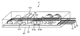
図3は電源装置4の鳥瞰図であり、図4は電源装置4の内部を長手方向側面から見た図であり、図5は図4の電源装置の内部を線a−a´から見た正面図である。電源装置4はケース40、ケース40に内包される回路基板50、回路基板50をケース40の内面から絶縁する絶縁シート60を備える。なお、本明細書においては、電源装置4(ケース40)の長手方向(図4の矢印の方向)を長手方向といい、各配線が引き出される側(図4における右側)を前方、その逆(図4における左側)を後方というものとする。
3 is a bird's-eye view of the
図3乃至図5を参照すると、ケース40は、側面部41、底板部42、側面部43、天板部44、前方端面45及び後方端面46を有する直方体からなる。前方端面45及び後方端面46に、底板部42を挟んで逆方向に突出する張出部45a及び46aが設けられる。張出部45a及び46aの取り付け孔45b及び46b(不図示)には挿通部材が挿通可能となっており、固定面への取り付けの際に利用される。前方端面45には各配線を引き出すための配線引き出し部45cが設けられる。従って、電源装置4は、ポール3の内部において、前方端面45を下方に、後方端面46を上方に向けて配置される。
3 to 5, the
図4及び図5を参照すると、回路基板50には、LED点灯回路を構成する部品群が実装され、部品群を挟んで入力側端部に入力配線51及び52並びにアース線55が接続され、出力側端部に出力配線53及び54が接続される。回路基板50がケース40に収容された場合に、入力側端部が前方端面45に対応し、出力側端部が後方端面46に対応する。回路基板50の上面では部品群が充填材70に覆われ、下面には各部品の半田付け部50sが点在する。なお、充填材70を回路基板50の下面側にも充填して半田付け部50sを覆い、放熱性を高めてもよい。
4 and 5, the
図6は絶縁シート60の鳥瞰図である。図4乃至図6を参照すると、絶縁シート60は、側面部61、底面部62、側面部63及び天面部64を備え、長手方向に延在して回路基板50を覆う。また、側面部61、底面部62、側面部63及び天面部64はケース40の側面部41、底板部42、側面部43及び天板部44の内面に近接して対向配置される。絶縁シート60は一枚のシートを折り曲げ加工して形成され、絶縁シート60によって画定される前方端及び後方端は開放されている。なお、絶縁シート60の展開図においては側面部61と天面部64が最遠部となっており、従って、図6における側面部61と天面部64の境界は折り曲げ加工によるものではない。
FIG. 6 is a bird's-eye view of the insulating
図4乃至図6を参照すると、絶縁シート60の前方端はケース40の前方端面45に到達しない位置に配置され、後方端はケース40の後方端面46の内面と実質的に一致する位置に配置される。絶縁シート60には、側面部63と天面部64の境界に沿って、即ち、天面部64のエッジに沿って回路基板50側に凹んだ溝65が設けられる。溝65の後方側には、後方端面46の内面と絶縁シート60の間に空間ができるように切り欠き部65aが設けられる。
4 to 6, the front end of the insulating
切り欠き部65a及び溝65には、出力配線53及び54が挿入される。即ち、出力配線53及び54は、回路基板50の出力側端部から後方端面46に沿って切り欠き部65aに達し、溝65内を這って前方端面45付近に達し、配線引き出し部45cからケース外部に引き出される。一方、入力配線51及び52並びにアース線55は、回路基板50の入力側端部から配線引き出し部45cにほぼ最短距離で達してそこから引き出される。
The output wirings 53 and 54 are inserted into the notch 65a and the
なお、本実施例では、絶縁シート60の前方端はケース40の前方端面45に到達しない位置に配置されているが、後方端と同様に、前方端がケース40の前方端面45の内面と実質的に一致する位置に配置され、前方端面45との間に空間ができるように切り欠き部が形成されるようにしてもよい。
In the present embodiment, the front end of the insulating
図4及び図5を参照すると、絶縁シート60内側の回路基板50が占める空間には、絶縁物(樹脂)からなる充填材70が充填され、充填材70は個々の回路部品を覆っている。充填材70は、密閉構造となるケース40内における回路部品の温度上昇を抑制する放熱設計を目的とするものである。
4 and 5, the space occupied by the
回路基板50には、例えば図7に示すようなLED点灯回路500が実装される。LED点灯回路500は交流電流を直流電源に変換する降圧コンバータからなる。LED点灯回路500は、入力端子T1及びT2、出力端子T3及びT4、並びにアース端子E1を有する。入力端子T1及びT2には、入力線51及び52がそれぞれ接続され、出力端子T3及びT4には、出力線53及び54がそれぞれ接続され、アース端子E1にはアース線55が接続される。例えば、回路基板50がアース端子E1の部分でネジ留め等によりケース40の一部、例えば、底板部42の内面に接続される。
For example, an
LED点灯回路500は絶縁型フライバックコンバータからなり、整流回路510(ダイオードブリッジ)、平滑コンデンサ511、トランス512、トランス512の一次巻線をスイッチングするスイッチング素子513a及び513b(例えば、MOSFET)、並びにトランス512の二次巻線の電圧を整流平滑する整流素子514(ダイオード)及び平滑コンデンサ515を備える。回路効率を向上するために、同じ素子からなるスイッチング素子513a及び513bが並列接続される。さらに、安定動作のために、平滑コンデンサ511と平滑コンデンサ512を接続する結合コンデンサ516が接続されていてもよい。PWM制御回路517はドライバIC等を含み、LEDモジュール基板21への出力電流が所定値となるように、スイッチング素子513a及び513bをPWM制御する。なお、図7はオープンループの制御回路を示しているが、出力ラインに流れる電流を抵抗等により検出して電流フィードバックを行う構成としてもよい。また、本実施例では、LED点灯回路500として絶縁型のフライバックコンバータを採用するが、LED点灯回路は非絶縁型の降圧チョッパ回路等からなっていてもよい。
The
アース端子E1は、入力端子T1とT2の間に直列接続されるコンデンサ501及び502の接続点、並びに一端が出力ライン上のノードN4に接続されたコンデンサ503の他端に接続される。なお、コンデンサ503は、トランス512の2次側のノードN3又は1次側のノードN1若しくはN2とアース端子E1の間に接続されるようにしてもよい。
The ground terminal E1 is connected to the connection point of the
次に、電源装置4の作製方法について説明する。図8は電源装置4の作製工程を示すフローチャートである。
まず、ステップS10において、側面部41、底板部42、側面部43及び天板部44からなるケース本体部が押し出し加工される。
Next, a method for manufacturing the
First, in step S <b> 10, the case main body portion including the
ステップS20において、LED点灯回路500及び各配線ケーブル(51−55)が実装された回路基板50が絶縁シート60に内包された状態で、ケース本体部の内部に固定される。ステップS20において、出力配線53及び54は上述したように絶縁シート60の切り欠き部65a及び溝65に挿入される。
ステップS30において、後方端面46がケース本体部の後方開口端面にネジ留め等により固定される。なお、ステップS20とS30の順序は逆でもよい。
In step S <b> 20, the
In step S30, the
ステップS40において、樹脂充填材がケース本体部の前方開口端面から内部に注入される。その後乾燥等により充填材が固められる。 In step S40, the resin filler is injected into the inside from the front opening end face of the case main body. Thereafter, the filler is hardened by drying or the like.
ステップS50において、回路基板50からの配線ケーブル(51〜55)が配線引出し部45cから引き出されつつ、前方端面45がケース本体部の前方開口端面にネジ留め等により固定される。これにより、電源装置4が完成する。なお、必要に応じて、配線引き出し部45cの防水処理を行うようにしてもよい。
なお、ステップS30及びS50において、前方端面45及び後方端面46のケース本体部への固定は、ネジ留めに限られず、嵌合箇所による係合、接着等の他の方法によって固定してもよい。
In step S50, the
In steps S30 and S50, the fixing of the
上述したように、本発明では、出力配線53及び54が絶縁シート60の側面部63と天面部64の間の境界に形成された溝65に這設されて絶縁シートお60の外面とケース40の内面の間に配置される。このような配線の引き回し構成には、比較例となる電源装置4´と比べて以下に示す幾つかの有利な効果がある。図13は、比較例の電源装置4´の姿図であり、図14はその内部正面図であり、以下の説明において参照される。なお、図13においては、説明の便宜上、充填材を省略している。
As described above, in the present invention, the
第1に、本実施例の配線引き回し構成によってノイズ低減の効果が得られる(ノイズ低減効果)。比較例の電源装置4´のように、出力配線53及び54を絶縁シート60´の内側に配置した場合、出力配線53及び54は回路部品と近接して引き回される可能性がある。特に、スイッチング素子513a及び513b、整流素子514、トランス512等の高周波で動作する回路部品(以下、「高周波部品」という)に出力配線53及び54が近接して配置されると、出力配線53及び54による直流出力にそのスイッチングノイズ(高周波ノイズ)が重畳されてしまう。これにより、ケース40外部に引き出された出力配線53及び54からの輻射ノイズが増大し、あるいはノイズの大きさによっては、半導体であるLEDの故障の原因ともなる。また、出力配線53及び54と近接する入力配線51及び52に対しても、上記の高周波部品からのノイズが載り易くなり、入力側の雑音端子電圧又は妨害電力の特性が損なわれる。さらに、出力配線53及び54の位置が複数の電源装置間で一定しないため、これらのノイズ特性のばらつきの管理も難しくなる。
First, the noise reduction effect can be obtained by the wiring routing configuration of this embodiment (noise reduction effect). When the
これに対して、本実施例のように、出力配線53及び54が絶縁シート60とケース40の内面の間に引き回されることにより、出力配線53及び54と上記の高周波部品との離隔距離が確保される。これにより、出力配線53及び54の出力に高周波部品からの高周波ノイズが載ることが防止され、比較例の電源装置4´で問題となるような出力配線53及び54に関するノイズの問題を解消することができる。
On the other hand, as in the present embodiment, the
なお、上記のノイズ低減効果は、充填材70の有無又は多少にかかわらず得られるものである。従って、充填材70の代わりに他の放熱設計(放熱フィン、外部からの空冷等)が施されるスイッチング電源においても、本発明の構成により第1の効果が得られる。
The noise reduction effect described above can be obtained regardless of the presence or absence of the
第2に、本実施例の配線引き回し構成によると、確実に絶縁距離又は絶縁性が確保されるという効果がある(絶縁性確保の効果)。通常、回路設計において、配線を含めた各電気部材間には、それらの電位差に応じた所定の絶縁距離が確保されるか、又は絶縁部材が介在される必要がある。従って、出力配線53及び54が絶縁シート60とケース40の内面の間に引き回されることにより、出力配線53及び54と各回路部品との絶縁距離が確実に確保され、又は絶縁シート60の本来の目的により絶縁性が確保される。本実施例では光源がLEDアレイであるが、この効果は、光源が高圧放電灯の場合に特に有利になる。これは、光源が高圧放電灯の場合、その始動時に高圧放電灯に印加すべき高圧パルスを出力する出力配線と他の部品との間の絶縁距離の確保が重要な問題となるからである。
Secondly, according to the wiring routing configuration of the present embodiment, there is an effect that the insulating distance or the insulating property is surely ensured (the effect of ensuring the insulating property). Usually, in circuit design, it is necessary to ensure a predetermined insulation distance corresponding to the potential difference between the electric members including the wiring or to interpose an insulating member. Therefore, the
第3に、本実施例の配線引き回し構成によると、電子部品が確実に充填材、即ち、放熱材に接触して覆われることが可能となる(放熱性確保の効果)。図13及び図14に示す比較例の構成では、回路部品、特に発熱部品に対する出力配線53及び54の位置を管理するのは難しく、出力配線が回路部品に接触した状態で充填材が充填される可能性がある。このような場合には、充填材がその回路部品に密着せず、充填材による回路部品の所望の放熱効果が得られなくなる。一方、本実施例にように、出力配線53及び54が絶縁シート60の外側に引き回されることにより、回路部品は確実に充填材に接触して覆われ、所望の放熱設計が実現される。
Thirdly, according to the wiring routing configuration of the present embodiment, the electronic component can be reliably covered and covered with the filler, that is, the heat dissipation material (effect of ensuring heat dissipation). In the configuration of the comparative example shown in FIGS. 13 and 14, it is difficult to manage the positions of the
第4に、本実施例の配線引き回し構成によると、電源装置4の作製時の充填材の注入工程において出力配線53及び54が邪魔にならず、作業性が向上するという効果がある(作製容易性の効果)。図13及び図14に示す比較例の構成では、充填材の注入工程において、絶縁シート60´の前方開口端面内に、入力配線51及び52、出力配線53及び54並びにアース線55が存在する。そのため、これらの5本の配線をよけて充填材の注入作業を行う必要がある。一方、本実施例によると、絶縁シート60の前方開口端面内には、入力配線51及び52並びにアース線55だけが存在することになる。入力配線51及び52並びにアース線55はケース断面下方に、出力配線53及び54はケース内面際(本実施例では、断面上方)に寄っているので、充填材注入作業においてこれらの配線が邪魔になることはない。このように、本実施例の引き回し構成は電源装置4の作製作業においても有利なものとなる。
Fourth, according to the wiring routing configuration of the present embodiment, the
第5に、本実施例の配線引き回し構成によると、配線51〜55のいずれも充填材中に固着されることはない。従って、電源装置4の寿命終了後の廃棄の段階において、線材の分別回収が容易となり、廃棄作業において有利なものとなる(廃棄容易性の効果)。
Fifth, according to the wiring routing configuration of the present embodiment, none of the
以上に本発明の好適な実施例を示したが、本発明の趣旨を逸脱しない範囲で、以下のような種々の変形が可能である。例えば、上記実施例では、絶縁シート60の溝65が側面部63と天面部64の境界に沿って形成される構成を示したが、溝の形態又は位置はこれに限られない。
Although the preferred embodiments of the present invention have been described above, various modifications as described below are possible without departing from the spirit of the present invention. For example, in the said Example, although the groove |
図9は第1の変形例による電源装置4の内部正面図である。図9に示すように、側面部63と天面部64との境界部に沿って欠け部66を設け、この欠け部66とケース40の内面に形成される空間に出力配線53及び54が這設される。上記実施例の場合と比べて絶縁シート60の折り曲げ加工数が少なくなり、作製効率において有利なものとなる。但し、出力配線53及び54は、絶縁シート60だけでは保持又は位置固定されず、ケース40に回路基板50及び絶縁シート60が挿入されて始めて位置が定まることに留意する必要がある。
FIG. 9 is an internal front view of the
図10は第2の変形例による電源装置4の内部正面図である。図10に示すように、天面部64にその長手方向に沿ってV字状の溝67が形成され、溝67内に出力配線53及び54が這設される。溝67の短手方向(図10における左右方向)の位置を、出力配線53及び54と回路基板50との接続位置又は配線引出し部45cの位置を考慮して設定することにより、出力配線53及び54のケース内距離を短くすることができる。また、溝67は必ずしも長手方向に平行でなくてもよい(即ち、絶縁シート60の開放端面に対して垂直でなくてもよい)。V字状の溝の代わりに矩形(凹状)の溝としてもよいが、この場合には上記実施例の場合と比べて、絶縁シート60の折り曲げ加工数が多くなることに留意する必要がある。
FIG. 10 is an internal front view of the
図11は第3の変形例による電源装置4の内部正面図である。図11に示すように、天面部64が、長手方向に沿うV字状の凹面68として形成され、凹面68の最深部付近に出力配線53及び54が這設される。この構成によって、上記実施例及び第2の変形例の場合と比べて絶縁シート60の折り曲げ加工数が少なくなり、作製効率において有利なものとはなる。ここで、出力配線の引き回し箇所にある程度自由度を持たせることができるが、逆に出力配線の位置は定まり難くなることに留意する必要がある。
FIG. 11 is an internal front view of the
図12は第4の変形例による電源装置4の内部正面図である。図12に示すように、側面部61にその長手方向に沿って矩形の溝69が形成され、溝69内に出力配線53及び54が這設される。溝69は、底板部42と天板部44の中心にある仮想の中心平面Pよりも天板部44側にある(なお、回路基板50は中心平面Pよりも底板部42側にある)。この構成によると、底面部62と天面部64の距離が長い場合(即ち、回路基板50が比較的高背に設計されている場合)に出力配線53及び54のケース内距離を短くすることができる。但し、出力配線53及び54が高周波部品の近傍を通過する可能性があることに留意する必要がある。
FIG. 12 is an internal front view of the
上記実施例及び変形例をまとめると、以下のことがいえる。
出力配線53及び54が這設される部分がケース40内面と絶縁シート60外面の間のいずれかの箇所に這設されることにより、上記の第2の効果(絶縁性確保)、第3の効果(放熱性確保)、第4の効果(作製容易性)及び第5の効果(廃棄容易性)を得ることができる。また、上記第1の効果(ノイズ低減)についても、出力配線53及び54の這設位置が最適でなかったとしても、出力配線53及び54の這設位置が所定位置に決まることにより、複数の電源装置間でのノイズ特性のばらつきが管理可能となる。
The following can be said by summarizing the above embodiments and modifications.
A portion where the
さらに、出力配線53及び54の這設部分は、底板部42及び天板部44から等距離にある仮想の中心平面よりも底板部42側に回路基板50が配置され、天板部44側に出力配線53及び54が這設されることが好ましい(溝65、欠け部66、溝67、凹面68、溝69参照)。この構成により、出力配線53及び54が、回路基板50の実装面から確実に離隔されることになり、上記第1の効果が確実に得られる。また、当然に第2〜第5の効果も得られる。
Further, the installed portion of the
またさらに、出力配線53及び54の這設部分は、絶縁シート60の天面部64の長手方向エッジ又は面上に配置されることがより好ましい(溝65、欠け部66、溝67、凹面68参照)。この構成により、出力配線53及び54が、回路基板50上の回路部品(特に高周波部品)から最遠の位置に配置されることが可能となる。これにより、上記の第1の効果が最大限に得られる。また、当然に第2〜第5の効果も得られる。そして、実施例で示したように、絶縁シート60の天面部64の長手方向エッジに沿って回路基板50側に凹んだ溝65に出力配線53及び54を這設させる構成とすることにより、配線が収容され易い矩形の溝を少ない折り曲げ加工数で実現することができる。
Furthermore, it is more preferable that the installed portions of the
本発明は、上述したように、LEDモジュールを光源とする道路灯用照明器具に適用されるスイッチング電源において特に有利な構成となることを想定している。しかし、光源が蛍光灯、高圧放電灯等の放電灯であり、回路基板に各光源に適した光源点灯回路が実装されるような他のスイッチング電源装置にも本発明を適用できる。また、道路灯用照明器具に限らず、スイッチング電源装置の長手方向が鉛直方向になるように設置される屋外用照明器具であれば、本発明の効果を享受できる。 As described above, the present invention assumes a particularly advantageous configuration in a switching power supply applied to a lighting device for a road lamp using an LED module as a light source. However, the present invention can also be applied to other switching power supply devices in which the light source is a discharge lamp such as a fluorescent lamp or a high-pressure discharge lamp, and a light source lighting circuit suitable for each light source is mounted on the circuit board. Moreover, the effect of this invention can be enjoyed if it is an outdoor lighting fixture installed so that the longitudinal direction of a switching power supply device may become not only the lighting fixture for road lights but a vertical direction.
1 道路灯用照明器具
2 灯具部
21 LEDモジュール基板
3 ポール
4 電源装置(スイッチング電源装置)
40 ケース
41、43 側面部
42 底板部
44 天板部
45 前方端面
45c 配線引き出し部
46 後方端面
50 回路基板
51、52 入力配線
53、54 出力配線
55 アース配線
500 LED点灯回路
60 絶縁シート
61、63 側面部
62 底面部
64 天面部
65、67、69 溝
65a 切り欠き部
66 欠け部
68 凹面
70 充填材
DESCRIPTION OF
40
Claims (9)
光源点灯回路を構成する部品群が実装され、該部品群を挟んで長手方向の一端に交流電源からの入力配線が接続され、他端に光源に電力を供給するための出力配線が接続された回路基板、
前記回路基板を前記基板長手方向にわたって覆う絶縁シート、及び
前記絶縁シートを介して前記回路基板を内包し、前記一端側に対応する端面に配線引き出し部を有するケース
を備え、
前記出力配線が前記ケースの内面と前記絶縁シートの外面の間に這設され、前記入力配線及び出力配線が前記配線引出し部から前記ケース外部に引き出され、かつ前記入力配線が前記配線引き出し部から実質的に最短距離で引き出された、スイッチング電源装置。 A switching power supply,
A component group constituting the light source lighting circuit is mounted, an input wiring from an AC power source is connected to one end in the longitudinal direction across the component group, and an output wiring for supplying power to the light source is connected to the other end Circuit board,
An insulating sheet that covers the circuit board in the longitudinal direction of the board; and a case that includes the circuit board via the insulating sheet and has a wiring lead-out portion on an end surface corresponding to the one end side;
The output lines are這設between the outer surface of the insulating sheet and the inner surface of the casing, said input lines and output lines is issued can pull on whether we said casing outside the wiring lead-out portion, and the input wiring the wiring It was substantially withdrawn at the shortest distance from the drawer unit, switching power supply.
前記底板部及び前記天板部から等距離にある仮想の中心平面よりも該底板部側に前記回路基板が配置され、該天板部側に前記出力配線が這設されたスイッチング電源装置。 The switching power supply device according to claim 1 or 2, wherein the case includes a rectangular parallelepiped having a bottom plate part, a top plate part, and a side part that define a longitudinal direction,
A switching power supply apparatus in which the circuit board is disposed on the bottom plate part side of a virtual center plane that is equidistant from the bottom plate part and the top plate part, and the output wiring is provided on the top plate part side.
前記光源が設置された灯具部、
上端が前記灯具部に結合され、下端が地中に埋設されるポール部、及び
前記ポール部内に、前記配線引出し部を有する端面を前記下端側に向けて配置された請求項1から7のいずれか一項に記載のスイッチング電源装置
を備えた道路灯用照明器具。 A lighting fixture for road lights,
A lamp unit in which the light source is installed,
Upper end coupled to the lamp unit, the pole portion lower end is buried in the ground, and into the pole part, according to claim 1 or et 7 the end face disposed toward the lower side with the wire lead-out portion A lighting device for a road lamp comprising the switching power supply device according to any one of the above.
(S10)底板部、側面部及び天板部からなるケース本体部を押し出し加工する工程と、(S10) a step of extruding the case main body portion including the bottom plate portion, the side surface portion, and the top plate portion;
(S20)光源点灯回路を構成する部品群が実装され、該部品群を挟んで長手方向の一端に入力配線が接続され、他端に光源に電力を供給するための出力配線が接続された回路基板を、絶縁シートに内包された状態でかつ前記出力配線が前記ケース本体の内面と前記絶縁シートの外面の間に這設された状態で前記ケース本体部の内部に固定する工程と、(S20) A circuit in which a component group constituting a light source lighting circuit is mounted, an input wiring is connected to one end in the longitudinal direction across the component group, and an output wiring for supplying power to the light source is connected to the other end Fixing the substrate to the inside of the case main body in a state of being included in an insulating sheet and the output wiring being provided between the inner surface of the case main body and the outer surface of the insulating sheet;
(S30)前記固定する工程(S20)の前又は後に、前記ケース本体部の前記他端側の開口端面に第1の端面を固定する工程と、(S30) before or after the fixing step (S20), a step of fixing the first end face to the opening end face on the other end side of the case body,
(S40)絶縁物からなる充填材を前記ケース本体部の前記一端側の開口端面から内部に注入し、前記充填剤を固める工程と、(S40) Injecting a filler made of an insulator into the inside from the opening end face on the one end side of the case body, and solidifying the filler;
(S50)前記一端側の開口端面に第2の端面を固定する工程であって、前記第2の端面の配線引出し部から前記入力配線及び前記出力配線を引き出しつつ前記第2の端面を固定する工程と(S50) A step of fixing the second end face to the opening end face on the one end side, and fixing the second end face while pulling out the input wiring and the output wiring from the wiring lead-out portion of the second end face. Process and
を備える製造方法。A manufacturing method comprising:
Priority Applications (1)
| Application Number | Priority Date | Filing Date | Title |
|---|---|---|---|
| JP2012204236A JP5994506B2 (en) | 2012-09-18 | 2012-09-18 | Switching power supply device and lighting device for road light |
Applications Claiming Priority (1)
| Application Number | Priority Date | Filing Date | Title |
|---|---|---|---|
| JP2012204236A JP5994506B2 (en) | 2012-09-18 | 2012-09-18 | Switching power supply device and lighting device for road light |
Publications (2)
| Publication Number | Publication Date |
|---|---|
| JP2014060848A JP2014060848A (en) | 2014-04-03 |
| JP5994506B2 true JP5994506B2 (en) | 2016-09-21 |
Family
ID=50616814
Family Applications (1)
| Application Number | Title | Priority Date | Filing Date |
|---|---|---|---|
| JP2012204236A Active JP5994506B2 (en) | 2012-09-18 | 2012-09-18 | Switching power supply device and lighting device for road light |
Country Status (1)
| Country | Link |
|---|---|
| JP (1) | JP5994506B2 (en) |
Families Citing this family (3)
| Publication number | Priority date | Publication date | Assignee | Title |
|---|---|---|---|---|
| JP6582923B2 (en) * | 2015-11-27 | 2019-10-02 | 岩崎電気株式会社 | LED lighting device and LED lighting device |
| JP2017199587A (en) * | 2016-04-28 | 2017-11-02 | 岩崎電気株式会社 | Light source lighting device and road light for outdoor lights |
| JP2020205737A (en) * | 2019-06-19 | 2020-12-24 | パナソニックIpマネジメント株式会社 | Power supply device and lighting equipment |
Family Cites Families (4)
| Publication number | Priority date | Publication date | Assignee | Title |
|---|---|---|---|---|
| JP4697108B2 (en) * | 2006-09-25 | 2011-06-08 | 東芝ライテック株式会社 | Lighting device and lighting apparatus |
| JP2008270165A (en) * | 2007-03-27 | 2008-11-06 | Matsushita Electric Works Ltd | Discharge lamp lighting device and lighting apparatus using it |
| JP2010153355A (en) * | 2008-11-26 | 2010-07-08 | Toshiba Lighting & Technology Corp | Electric equipment and illuminating device |
| JP5033215B2 (en) * | 2010-04-19 | 2012-09-26 | 株式会社因幡電機製作所 | Street light |
-
2012
- 2012-09-18 JP JP2012204236A patent/JP5994506B2/en active Active
Also Published As
| Publication number | Publication date |
|---|---|
| JP2014060848A (en) | 2014-04-03 |
Similar Documents
| Publication | Publication Date | Title |
|---|---|---|
| JP5574465B2 (en) | lamp | |
| CN203463999U (en) | Straight tubular lamp and illuminating apparatus | |
| JP5935612B2 (en) | Case for power supply device, LED power supply device, lighting device for road light and lighting device for tunnel light | |
| JP5564108B2 (en) | Apparatus and system for partitioning space | |
| EP2583536B1 (en) | Light-emitting apparatus and lighting appliance provided with the same | |
| US20180332731A1 (en) | Electrical junction box | |
| JP5994506B2 (en) | Switching power supply device and lighting device for road light | |
| CN109296995B (en) | LED lamp module and LED light source driving circuit | |
| CN106206459A (en) | Package assembling | |
| CN105873263A (en) | Lighting device and lighting tool | |
| JP6628176B2 (en) | lighting equipment | |
| JP5538550B2 (en) | Light source lighting device, manufacturing method thereof, and in-vehicle headlamp device | |
| JP5263592B2 (en) | LED lighting device and lighting apparatus | |
| JP4802807B2 (en) | Electromagnetic induction parts and power supply | |
| JP2013252006A (en) | Motor driving device and air conditioner including the same | |
| JP6252931B2 (en) | Lighting device and lighting apparatus using the same | |
| KR20140011783A (en) | Led lighting apparatus | |
| JP2010080381A (en) | Led lighting device and illumination apparatus | |
| JP2016010296A (en) | Power supply device and luminaire using the same | |
| JP4269460B2 (en) | Mounting structure of surface mount type semiconductor switch element | |
| JP6019934B2 (en) | LED power supply device and outdoor lighting fixture | |
| JP5057081B2 (en) | Lighting device | |
| JP7300644B2 (en) | Control devices, lighting devices, light source units and lighting fixtures | |
| JP6906174B2 (en) | Lighting device and lighting equipment | |
| JP2018166162A (en) | Lighting device, and lighting apparatus |
Legal Events
| Date | Code | Title | Description |
|---|---|---|---|
| RD04 | Notification of resignation of power of attorney |
Free format text: JAPANESE INTERMEDIATE CODE: A7424 Effective date: 20140121 |
|
| A621 | Written request for application examination |
Free format text: JAPANESE INTERMEDIATE CODE: A621 Effective date: 20150515 |
|
| A977 | Report on retrieval |
Free format text: JAPANESE INTERMEDIATE CODE: A971007 Effective date: 20160615 |
|
| A131 | Notification of reasons for refusal |
Free format text: JAPANESE INTERMEDIATE CODE: A131 Effective date: 20160628 |
|
| A521 | Request for written amendment filed |
Free format text: JAPANESE INTERMEDIATE CODE: A523 Effective date: 20160630 |
|
| TRDD | Decision of grant or rejection written | ||
| A01 | Written decision to grant a patent or to grant a registration (utility model) |
Free format text: JAPANESE INTERMEDIATE CODE: A01 Effective date: 20160726 |
|
| A61 | First payment of annual fees (during grant procedure) |
Free format text: JAPANESE INTERMEDIATE CODE: A61 Effective date: 20160808 |
|
| R150 | Certificate of patent or registration of utility model |
Ref document number: 5994506 Country of ref document: JP Free format text: JAPANESE INTERMEDIATE CODE: R150 |
|
| S531 | Written request for registration of change of domicile |
Free format text: JAPANESE INTERMEDIATE CODE: R313531 |
|
| R350 | Written notification of registration of transfer |
Free format text: JAPANESE INTERMEDIATE CODE: R350 |
|
| S111 | Request for change of ownership or part of ownership |
Free format text: JAPANESE INTERMEDIATE CODE: R313111 |
|
| R350 | Written notification of registration of transfer |
Free format text: JAPANESE INTERMEDIATE CODE: R350 |