JP5989021B2 - Folding helmet - Google Patents
Folding helmet Download PDFInfo
- Publication number
- JP5989021B2 JP5989021B2 JP2014044497A JP2014044497A JP5989021B2 JP 5989021 B2 JP5989021 B2 JP 5989021B2 JP 2014044497 A JP2014044497 A JP 2014044497A JP 2014044497 A JP2014044497 A JP 2014044497A JP 5989021 B2 JP5989021 B2 JP 5989021B2
- Authority
- JP
- Japan
- Prior art keywords
- connecting portion
- shell
- peripheral
- cap body
- center
- Prior art date
- Legal status (The legal status is an assumption and is not a legal conclusion. Google has not performed a legal analysis and makes no representation as to the accuracy of the status listed.)
- Active
Links
- 230000002093 peripheral effect Effects 0.000 claims description 98
- 210000000078 claw Anatomy 0.000 claims description 42
- 230000008878 coupling Effects 0.000 description 5
- 238000010168 coupling process Methods 0.000 description 5
- 238000005859 coupling reaction Methods 0.000 description 5
- 230000000694 effects Effects 0.000 description 4
- 239000000463 material Substances 0.000 description 2
- 229920003002 synthetic resin Polymers 0.000 description 2
- 239000000057 synthetic resin Substances 0.000 description 2
- 230000002950 deficient Effects 0.000 description 1
- 238000010586 diagram Methods 0.000 description 1
- 230000005489 elastic deformation Effects 0.000 description 1
- 238000000034 method Methods 0.000 description 1
- 238000000465 moulding Methods 0.000 description 1
- 230000003014 reinforcing effect Effects 0.000 description 1
- 238000003466 welding Methods 0.000 description 1
Images


Landscapes
- Helmets And Other Head Coverings (AREA)
Description
この発明は、平常時には折り畳んでおき、例えば地震などの非常時あるいは作業を行う場合に、迅速に組み立てて使用することができる折り畳みヘルメットに関し、折り畳み状態から使用状態に迅速に移行し、使用状態を確実に維持することができる構造に係る発明である。 The present invention relates to a folding helmet that can be folded during normal times and can be quickly assembled and used in the event of an emergency such as an earthquake or when working, for example. This invention relates to a structure that can be reliably maintained.
主として、地震や火災といった非常時に使用することができる折り畳み式の帽子やヘルメットが、従来から提案されている。
特許文献1には、折り曲げ部で連続する前頭部を覆う前側の平板と、後頭部を覆う後側の平板とで構成し、折り曲げ部で折り曲げることによって偏平状態となり、折り曲げ部を左右両側から狭めることによって帽子形状が形成される構造が開示されている。
特許文献2には、前側平板と後側平板と両者の周縁の一部を連結部で連結する折り畳み式帽子であって、側辺部を互いに接近させることによって帽子の形状となるものであって、側辺部を接近させるための紐をレバー操作によって行う構造が開示されている。
Conventionally, a foldable hat or helmet that can be used in an emergency such as an earthquake or fire has been proposed.
本発明者らは、よりヘルメットとしての形状、強度を実現する折り畳みヘルメットとして、略半球殻状の帽体を、頭頂部中心を通る中心線に沿って二つの半帽体に分割し、二つの半帽体は、それぞれ下端開口縁から上方の一定範囲を占める中央殻と、中央殻に隣接する複数の周辺殻に区画し、中央殻と周辺殻は回動可能なヒンジ構造で連続させ、一つの半帽体における周辺殻と周辺殻は分離させて当接可能な状態とするとともに、外周に位置する二つの半帽体の対応する周辺殻と周辺殻は回動可能なヒンジ構造で連結する折り畳みヘルメットを発明した。(特許文献3)
このヘルメットは、前方に位置する周辺殻と周辺殻の連結部分と、後方に位置する周辺殻と周辺殻の連結部分を操作紐で引き寄せることによって使用状態に維持することができるものである。
The present inventors divided a substantially hemispherical cap body into two hemicap bodies along a center line passing through the center of the top of the head as a folding helmet that realizes a shape and strength as a helmet more, The half-cap body is divided into a central shell occupying a certain range above the opening edge of the lower end and a plurality of peripheral shells adjacent to the central shell, and the central shell and the peripheral shell are continuously connected by a pivotable hinge structure. Peripheral shells and peripheral shells in one half-cap body are separated and can be brought into contact with each other, and the corresponding peripheral shells and peripheral shells of the two half-cap bodies located on the outer periphery are connected by a pivotable hinge structure. Invented a folding helmet. (Patent Document 3)
This helmet can be kept in use by pulling the connecting portion between the peripheral shell and the peripheral shell located at the front and the connecting portion between the peripheral shell and the peripheral shell located at the rear with an operating string.
特許文献1に記載された発明は、帽子として使用する場合に、後側及び前側の平板を弾性に抗して強い力で押し縮める必用があり、帽子(ヘルメット)として組み立てる操作が必ずしも容易ではない。特に女性、子供のような力の弱い人には組み立てが困難であるという欠点があった。また、ヘルメットとしての強度は、組立時に使用者が湾曲させる後側及び前側の平板の強度に依存し、十分な強度を備えることが困難である。すなわち、頭部を覆う後側及び前側の平板の強度を向上させるためには、例えば平板の板厚を大きくする必用があり、板厚を大きくすると組立操作の弾性変形が困難となる。
特許文献2に記載された発明は、特許文献1に記載された発明の組み立てに際し、レバー操作で後側及び前側の平板を弾性に抗して縮めることができるものであるが、使用状態の形状がヘルメットとして不自然であり、十分な強度を備えることが困難なものである。
When the invention described in
In the invention described in
本出願人の、先の出願に係る折り畳みヘルメットは、自然なヘルメット形状であって、ヘルメットとしての十分な強度を実現することができる。しかしながら、先の出願の明細書に記載した構造の操作紐(締付紐)は、ヘルメットを使用状態とするために操作紐を引っ張り出して周辺殻と周辺殻の連結部を引き寄せて、帽状のヘルメット形状としている。また、ヘルメット形状を使用状態に維持するための構造として、引っ張り出した操作紐が引き戻されないようなロック手段を設けている。
なお、帽子(ヘルメット)としての使用状態を維持するために、引用文献2に記載された発明は、平板を弾性に抗して縮めた状態とするために、レバーによって紐を引っ張った状態に維持する構成としている。
The folding helmet according to the previous application of the present applicant has a natural helmet shape and can realize sufficient strength as a helmet. However, the operation cord (clamping cord) having the structure described in the specification of the previous application is pulled out of the operation cord to bring the helmet into use, and the connecting portion between the peripheral shell and the peripheral shell is drawn to form a cap shape. It has a helmet shape. Further, as a structure for maintaining the helmet shape in use, a lock means is provided so that the pulled-out operating string is not pulled back.
In order to maintain the use state as a hat (helmet), the invention described in the cited
上記、本出願人の先の出願に係る折り畳みヘルメットでは、使用状態に維持するために引出した操作紐(締付紐)が、後頭部に垂れ下がったままの状態となるため、ヘルメットとして使用する際、垂れ下がった紐が邪魔になる可能性があった。また、使用中に操作紐のロック手段が緩むようなことがあると、頑丈なヘルメット形状を維持することが困難になる場合があった。
さらに、ヘルメットを使用状態とする操作紐の操作が必ずしも容易ではなく、使用状態とするために引出した操作紐が、外部に垂れ下がるなどの欠点があった。本発明は、このような、本出願人による先の出願の欠点を解消することを目的とするものである。
In the folding helmet according to the above-mentioned previous application of the present applicant, since the operation string (tightening string) pulled out to maintain the use state remains hanging on the back of the head, when used as a helmet, The hanging string could get in the way. Further, if the lock means of the operation string is loosened during use, it may be difficult to maintain a sturdy helmet shape.
In addition, the operation of the operation cord for using the helmet is not always easy, and the operation cord pulled out for use is deficient in that it hangs down. The present invention aims to eliminate the disadvantages of the previous application by the applicant.
上記目的を達成する本発明に係る折り畳みヘルメットは、略半球殻状の帽体1を、頭頂部中心を通る中心線に沿って二つの半帽体2、3に分割し、分割した二つの半帽体は、それぞれ対向位置に下端開口縁から上方の一定範囲を占める中央殻2a、3aと、中央殻2a、3aに隣接する複数の周辺殻2b〜2d、3b〜3dに区画し、中央殻と周辺殻は回動可能なヒンジ構造で連続させる。一つの半帽体における周辺殻と周辺殻は分離させて当接可能な状態とするとともに、二つの半帽体の対応する位置の周辺殻と周辺殻は、回動可能なヒンジ構造の連結部4〜6で連結するものである。
The folding helmet according to the present invention that achieves the above-mentioned object is obtained by dividing a substantially
請求項1記載の発明は、隣接する連結部と連結部との間に係合手段を設け、帽体1を押圧して前方位置の連結部と後方位置の連結部を強制的に接近させて、隣接する連結部と連結部を係合させることによって使用状態に維持するとともに、前記連結部と連結部の係合を解除し連結部の側方から帽体を押圧して連結部と連結部を離すことによって扁平な折り畳み状態とする折り畳みヘルメットである。
前記、連結部の構造は、二つの半帽体2、3の周辺殻2b〜2d、3b〜3dに薄肉部によって連続させて形成した連結片4a〜5aと連結片4b〜5bを嵌合させるとともに、この連結片と連結片の嵌合部の上方を連結片に固定する連結部カバー4g〜6gで覆い、連結部カバーに連結爪7と連結爪7に係合する係合部10を形成するものである。
In the first aspect of the present invention, the engaging means is provided between the adjacent connecting portions, and the
The structure of the connecting portion is such that the connecting
請求項2記載の発明は、中央に位置する連結部4の前方端及び後方端にそれぞれ連結爪7、7を配置し、前記中央に位置する連結部4の前方端に設けた連結爪7を前方に位置する連結部5に、中央に位置する連結部4の後方端に設けた連結爪7を後方に位置する連結部6に係合させる請求項1記載の折り畳みヘルメットである。
In the invention according to
請求項3記載の発明は、中央に位置する連結部4の前方端及び後方端に配置する連結爪7、7は、先端に係止部8を形成し基端を中央に位置する連結部4に軸支し、バネ9によって先端の係止部8を下方に向けて付勢するとともに、前方の連結部5の後端部定位置および後方の連結部6の前端部定位置に、連結爪7の係止部8が係合する係合部10を形成する。
前記連結爪7の前端面7aは、係止部8が連結部の一部を乗り越えて係合部10に誘導される傾斜面に形成されている請求項2記載の折り畳みヘルメットである。
According to the third aspect of the present invention, the connecting
The
請求項4記載の発明は、中央に位置する連結部4の前方端及び後方端と、前方に位置する連結部5の後方端及び後方に位置する連結部6の前方端のいずれか一方の定位置に位置決め突起11を、いずれか他方の定位置に前記位置決め突起が嵌合する嵌合部を形成したことを特徴とする請求項1〜3のいずれかに記載の折り畳みヘルメットである。
The invention according to
請求項5記載の発明は、複数の連結部4〜6のうちの一つは、二つの半帽体の周辺殻に薄肉部によって連続させて一体の連結片6aとして形成し、この一体に形成した連結片6aの上方に連結部カバー6gを固定することである。
Invention 請 Motomeko 5 wherein the one of the connection portion 4-6 of the multiple is made continuous by the thin-walled portion formed as a connecting
請求項1記載の発明によれば、帽体1を押圧して前方位置の連結部と後方位置の連結部を強制的に接近させることによって、隣接する連結部と連結部を係合させ、扁平に折り畳まれていたヘルメットを容易に使用状態のヘルメット形状に変更することができる。そして、連結部の係合によってヘルメット形状を確実に維持し、ヘルメットとして安全に使用することができる。
そして、連結部と連結部の係合を解除し、連結部の側方から帽体を押圧することによって、容易に扁平な状態に折り畳むことができる。
According to the first aspect of the present invention, the
And it can fold to a flat state easily by canceling | releasing engagement of a connection part and a connection part, and pressing a cap body from the side of a connection part.
請求項2記載の発明によれば、中央に位置する連結部4の前方端及び後方端にそれぞれ連結爪7、7を配置し、この連結爪を前方に位置する連結部5と後方に位置する連結部6に係合させるため、バランスよく連結されるとともに、帽体1を押圧し連結爪7を係合させるに際し、左右対称的に操作することによって確実に係合させることができる効果がある。
According to the second aspect of the present invention, the connecting
請求項3記載の発明によれば、折り畳まれたヘルメットを使用状態とする際、帽体を押圧することによって連結部と連結部を接近させると、連結爪7の前端面7aが対向する連結部に当接し、さらに押圧するとバネ9の力に抗して連結爪が持ち上げられて連結部の一部を乗り越え、係止爪7の係止部8が対向する連結部の係合部10に自動的に係合するため、簡単かつ確実に使用状態に組み立てることができる。また、使用状態としたヘルメットは、バネ9の力で連結爪7の係合状態を確実に維持し、組み立てたヘルメットを安心して着用することができる。
According to the third aspect of the present invention, when the folded helmet is put into use, when the connecting portion and the connecting portion are brought close to each other by pressing the cap body, the connecting portion where the
請求項4記載の発明によれば、使用状態におけるヘルメット形状を確実に保持するとともに、連結部カバー4g〜6gは補強部品として機能し、ヘルメットとしての強度を向上させる効果がある。
請求項5記載の発明によれば、右側の半帽体2と左側の半帽体3を一体に成型し、能率的に製造することができる効果がある。
According to the fourth aspect of the present invention, the shape of the helmet in use is securely held, and the connecting portion covers 4g to 6g function as reinforcing parts, and have an effect of improving the strength as a helmet.
According to the invention of
以下、本発明に係る折り畳みヘルメットの実施形態を添付の図面に基づいて説明する。
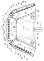
図1はヘルメットの帽体全体の後方斜視図、図2は平面図である。
図示実施形態の折り畳みヘルメットは、全体を例えば合成樹脂材によって成型するものであって、略半球殻状の帽体1を、頭頂部中心を通る前後方向の中心線に沿って二つの半帽体、すなわち右側の半帽体2と左側の半帽体3に分割する。
DESCRIPTION OF EMBODIMENTS Hereinafter, embodiments of a folding helmet according to the present invention will be described with reference to the accompanying drawings.
FIG. 1 is a rear perspective view of the entire helmet body, and FIG. 2 is a plan view.
The folding helmet of the illustrated embodiment is formed entirely of, for example, a synthetic resin material, and includes a substantially
右側の半帽体2及び左側の半帽体3は、それぞれ対向位置に下端開口縁から上方の一定範囲を占める中央殻2a、3aと、中央殻2a、3aに隣接する複数の周辺殻2b〜2d、周辺殻3b〜3dに区画する。
右側の半帽体2と左側の半帽体3は対称形とする。図2に示すように右側の半帽体2は、ほぼ中央にあって下端開口縁から上方に向けて一定範囲を占める右側の半帽体の中央殻2aと、この中央殻2aの上方に連続する中央に位置する周辺殻2bと、中央殻2aの前方に連続する周辺殻2cと、中央殻2aの後方に連続する周辺殻2dに区画する。右側の半帽体2の中央殻2aと、周辺殻2b、2c、2dは回動可能なヒンジ構造で連続させる。また、周辺殻2bと2c、周辺殻2bと2dの境界は分離させて当接可能な状態とする。
The right half-
The
左側の半帽体3は、前記右側の半帽体2と対称形である。すなわち、左側の半帽体3は、中央殻3aと、中央殻3aの上方に連続する周辺殻3bと、中央殻3aの前方に連続する周辺殻3cと、中央殻3aの後方に連続する周辺殻3dに区画している。左側の半帽体3の中央殻3aと周辺殻3b、中央殻3aと周辺殻3c及び中央殻3aと周辺殻3dは回動可能なヒンジ構造で連続させ、周辺殻3bと周辺殻3c及び周辺殻3dの境界は分離させて当接可能な状態としている。
左側の半帽体3の中央殻3a、周辺殻3b、3c、3dの形状や大きさは、前記右側の半帽体2の中央殻2a、周辺殻2b、2c、2dとそれぞれ対応させている。なお、周辺殻2b〜2d及び3b〜3dの側辺の当接状態は、当接位置において自然に係合もしくは嵌合し、当接状態が安定的に維持される構造とするのが好ましい。
The
The shape and size of the
図示実施形態においては、図6や図12から理解されるように、中央殻2a、3aを台形に形成し、下端開口縁を除く上方を直線的な三辺に区画し、中央殻の各辺の外方にそれぞれ周辺殻を配置している。すなわち、右側の半帽体2の中央殻2aの周辺に、中央位置の周辺殻2bと、前方位置の周辺殻2cと、後方位置の周辺殻2dを配置するとともに、左側の半帽体3の中央殻3aの周辺に、中央位置の周辺殻3bと、前方位置の周辺殻3cと、後方位置の周辺殻3dを配置している。中央殻の形状は台形以外の形状とし、中央殻の上辺の数を三辺以外とし、各辺の外方にそれぞれ周辺殻を配置するものであってもよい。
また、中央殻の大きさを小さなものとし、周辺殻の形状を扇形に近いものとすることもできる。しかしながら、ヒンジ構造の強度や一つの中央殻及び周辺殻の湾曲状態を考慮すると中央殻の大きさは周辺殻とバランスのとれた大きさとするのが好ましい。
In the illustrated embodiment, as understood from FIGS. 6 and 12, the
Further, the size of the central shell can be made small, and the shape of the peripheral shell can be made close to a sector. However, considering the strength of the hinge structure and the curved state of one central shell and the peripheral shell, the size of the central shell is preferably balanced with the peripheral shell.
中央殻と周辺殻のヒンジ構造は、例えば別部品による軸支構造であってもよいが、図示実施形態の折り畳みヘルメットでは、右側の半帽体2の中央殻2a及び左側の半帽体3の中央殻3aの外周を直線状に区画し、この直線部分において薄肉部13、13で中央殻2a、3aと周辺殻2b〜2d、3b〜3dをそれぞれ連続させることによって薄肉のヒンジ構造を実現し、全体を一体に成型している。
図示実施形態では、中央殻と周辺殻の区画を直線状としているが、例えば中央殻と周辺殻を曲線状に区画し、曲線の両端部においてのみヒンジ構造で連続させて回動可能な構造とすることもできる。
The hinge structure of the central shell and the peripheral shell may be, for example, a shaft support structure by separate parts, but in the folding helmet of the illustrated embodiment, the
In the illustrated embodiment, the central shell and the peripheral shell are made straight, but the central shell and the peripheral shell are partitioned in a curved shape, for example, and can be rotated continuously by hinge structures only at both ends of the curve. You can also
右側の半帽体2と左側の半帽体3の対応する周辺殻と周辺殻、具体的には周辺殻2bと3b、2cと3c、2dと3dは、それぞれ連結部4、5、6で連結されている。
上記、対応する周辺殻と周辺殻の連結部4、5、6は、回動可能な状態であればよく、周辺殻の外周辺どうしを、例えばピン構造で接続することもできる。図示実施形態においては、図14〜図16に示すように、右側の半帽体の周辺殻2b、2cと左側の半帽体の周辺殻3b、3cに、相互に嵌合する連結片4a、5a及び4b、5bを突出形成しておき、連結片4aと4b、5aと5bをそれぞれ嵌合させることによって連結している。連結片4a、5aは自由に折曲できる薄肉部4c、5cによって、連結片4b、5bは薄肉部4d、5dによってそれぞれ周辺殻2b、2c及び3b、3cに連続させている。
The corresponding peripheral shells and peripheral shells of the right
The corresponding peripheral shell-to-peripheral
連結片4a、5aと、連結片4b、5bの嵌合構造として、図15、図16に示すように一定の厚みの板状である一方の連結片4a、5aに、嵌合孔4e、5eを穿設し、他方の連結片4b、5bに、前記嵌合孔4e、5eに嵌合する嵌合突起4f、5fを形成している。
すなわち、右上の周辺殻2bと左上の周辺殻3b及び右前の周辺殻2cと左前の周辺殻3cの連結部4、5は、薄肉部4c、5c及び4d、5dによって周辺殻2、3と連続している。連結片4a、5aの嵌合孔4e、5eと、連結片4b、5bの嵌合突起4f、5fの嵌合によって中央の周辺殻2b、3b及び前の周辺殻2c、3cは強固に連結され、折曲自由な連結状態を実現している。
As the fitting structure of the connecting
That is, the
周辺殻2b〜2dと周辺殻3b〜3dの連結部4、5、6は、必ずしも前記嵌合状態で連結される構造である必要はなく、右半帽体の周辺殻と左半帽体の周辺殻は少なくとも折曲可能な薄肉部を備えた状態であれば、一体に成型するものであってもよい。
図示実施形態のヘルメットにおいて、右後の周辺殻2dと左後の周辺殻3dは、連結片6aと一体に成型することによって連結部6を形成している。一体である連結片6aは、周辺殻2d及び周辺殻3dと、薄肉部6cによって連続している。(図15における連結片6aと、図16における連結片6aは同じものを表している。)
The connecting
In the helmet of the illustrated embodiment, the right rear
右側の半帽体2の周辺殻2b、2cと、左側の半帽体3の周辺殻3b、3cとの連結は、着脱自在とする必要はなく、強固に連結状態が維持されるものであるのが好ましい。そのため、たとえば、右側の半帽体の周辺殻2b、2cと、左側の半帽体の周辺殻3b、3cの嵌合部分は、嵌合孔5dと嵌合突起5eは無理嵌めの嵌合状態、あるいは嵌合状態で溶着や接着によって一体化するものであるのが好ましい。
上記、周辺殻と周辺殻の連結部4、5、6には、その上方を覆う連結部カバー4g〜6gを装着している。すなわち、中央の連結部4には中央の連結部カバー4gを、前方の連結部5には前方の連結部カバー5gを、後方の連結部6には後方の連結部カバー6gを装着している。
The connection between the
The above-mentioned peripheral shell and peripheral
連結部4〜5の上方には、それぞれ、連結部カバー4g、5g、6gを配置することによって、帽体1の上面に露出する可能性がある連結部分の構造を連結部カバーで覆うことができる。また、連結部カバー4g、5g、6gによって、帽体の外観を見栄えよくするとともに、連結部5の強度、換言すれば帽体全体の強度を向上させることができる。すなわち、連結片4a〜6a(4b、5b)の上方に配置する連結部カバーは、図6から理解されるように、連結されている連結片4a、4bに対して固定部材14で連結部カバー4gを固定している。同じように、連結されている連結片5a、5bに対して固定部材14で連結部カバー5gを固定するとともに、連結片6aに対して固定部材14で連結部カバー6gを固定している。
なお、本発明において、連結部4、5、6とは左右の半帽体2、3の連結片4a、4b、5a、5bが直接連結している部分だけでなく、連結部カバー4g〜6gを含め連結部分全体を指すものである。
The structure of the connecting portion that may be exposed on the upper surface of the
In the present invention, the connecting
半帽体2、3の周辺殻2bと3b、2cと3c、 2dと3dの連結部4、5、6には、連結部どうしを相互に連結する係合手段を設けている。係合手段は、連結部4〜6のいずれの部分に設けても、相互に係合して連結状態を維持することができるものであればよいが、本実施形態においては、連結部カバー4g〜6gが相互に係合するように係合手段を形成している。
In the
具体的には、中央に位置する周辺殻2bと3bの連結部4にある連結部カバー4gの前方端及び後方端にそれぞれ連結爪7、7を配置し、前方端に設けた連結爪7を、前方に位置する連結部5の連結部カバー5gに形成した係合部10に、連結部カバー4gの後方端に設けた連結爪7を後方に位置する連結部6の連結部カバー6gに形成した係合部10に係合させることによって、連結部4〜6を一連に連結するようにしている。
Specifically, the connecting
図13から理解されるように、中央に位置する連結部4(連結部カバー4g)の前方端及び後方端に配置する連結爪7は先端に係止部8を形成し、基端を中央に位置する連結部カバー4gに軸支し、バネ9によって先端の係止部8を下方に向けて付勢している。一方、前方の連結部5の連結部カバー5gの後端部定位置および後方の連結部6の前端部定位置には、連結爪7の係止部8が係合する係合部10を形成している。さらに、連結爪7の前端面7aは係止部が連結部の一部を乗り越えて係合部に誘導される傾斜面、すなわち、下向きの傾斜面に形成している。
As can be understood from FIG. 13, the connecting
以上述べた構造とすることによって、図示実施形態のヘルメットは折り畳まれているヘルメットを簡単に使用状態に組み立てることができる。
すなわち、図8ないし図12に示すヘルメットの折り畳み状態では、半帽体2、3はいずれも図12に示す如く、扁平な展開形状であって連結部4、5、6は離れた位置にある。 このヘルメットを前後方向、すなわち連結部5と連結部6を両手で挟むように押圧すると、半帽体2、3の周辺殻2b、2c、2d及び3b、3c、3dが強制的に接近される。このとき、半帽体2、3の中央殻2a、3aと周辺殻2b、2c、2d及び3b、3c、3dは、薄肉部13、13で折曲されながら次第に帽体形状に変化していく。
With the structure described above, the helmet according to the illustrated embodiment can be easily assembled into a use state.
That is, in the folded state of the helmet shown in FIG. 8 to FIG. 12, the
図13(a)に示すように、折り畳み状態では連結部4と5が離れた位置にある。連結部4、5、6の両端部を両手で挟むように押圧すると、矢印で示すように連結部4と5、4と6が接近すると、連結爪7の前端面7aが前方の連結部カバー5gの後端部5hに当接し、連結爪7は前端面7aの傾斜面に沿って持ち上げられる。そして、連結爪7の係止部8の先端が連結部カバー5gの上面5iに沿って移動し、図13(b)に示すように所定位置に配置されている係合部10にカチンと係合する。連結爪7が係合部10に係合した状態では、バネ9の弾性によって連結爪7の連結状態が維持され、ヘルメットとして安心して着用することができる。
As shown in FIG. 13 (a), in the folded state, the connecting
使用状態のヘルメットを折り畳む場合は、図13(c)に示すように、バネ9の弾性に抗して手指で連結爪7を起こして係合を外し、帽体1を左右(連結部の側方)から押圧する。帽体1を左右から押圧すると、ヘルメットは扁平になりつつ図13(a)に示すように連結部4、5、6が離れた位置に移動して折り畳み状態とすることができる。折り畳み状態においては、図11に示すように折り畳んだヘルメットの開口縁、具体的には中央殻2aと3aの下端にロック爪15を、係脱自在に掛け渡すことによって折り畳み状態を維持することができる。
When the helmet in use is folded, as shown in FIG. 13 (c), the
前記、中央の連結部カバー4gの前方端と後方端に配置する連結爪7は、図18に示すように、基端部に支持軸16を、先端に係止部8を形成して合成樹脂材によって一体に形成している。すなわち、扁平な指掛け部17の前端部分に係止部8を形成し、その前面を前端面7aとしている。基端部の側方に突出させた支持軸16は、中央に位置する連結部カバー4gの表面に形成した凹所18に挿入して軸受け部としている。
As shown in FIG. 18, the connecting
中央に位置する連結部カバー4gの前後両端部には、連結爪7の下位置に前方及び後方に向けて突出する位置決め突起11を形成している。また、位置決め突起11と対向する連結部カバー5gの後端面、6gの前端面には、前記位置決め突起が嵌合する嵌合部を設けている。すなわち、位置決め突起11を略方形の突出杆とし、嵌合部12は位置決め突起が挿入される方形孔とするとともに、連結部カバー4gと5g、4gと6gが接近すると自然と挿入されて嵌合する形状としている。
このようにすると、連結部カバー4gと5g及び6gは、連結爪7と係合孔10及び位置決め突起11と嵌合部の上下二か所で係合することになるため、位置ずれやガタツキを無くし、しっかりと連結されることになる。したがって、位置決め突起11と嵌合部は、自然に案内されて嵌合するとともに、ガタツキなく嵌合する形状であることが望ましい。
In this case, the connecting portion covers 4g, 5g, and 6g are engaged at the upper and lower portions of the connecting
帽体1の外表面は、完全な球面、すなわち曲面で形成するものであってもよいが、必ずしも厳密な球面である必要はない。図示実施形態の帽体1は、半帽体2、3を構成する中央殻2a、3aや周辺殻2b〜2d、3b〜3dの表面を平面に形成している。中央殻2a、3aや周辺殻2b〜2d、3b〜3dの表面を平面とした場合、帽体の表面は多面体で構成されることになる。すなわち、本発明における半球殻状の帽体とは、厳密な球面だけでなく図示例のように多面体を含めた広義の球面を意味する。
The outer surface of the
図8〜図11に示す折り畳み状態のヘルメットの、折り畳み状態の厚みTは、対向する中央殻(2aと3a)及び周辺殻(2bと3b 、2cと3c 、2dと3d)の外接寸法となる。したがって、中央殻2a、3a及び周辺殻2b〜2d、3b〜3dの外表面が球殻状ではなく、図示実施形態のように平面で形成されている場合は、折り畳み状態の厚みTをなるべく小さくすることができる。折り畳み状態の厚みTが小さくなると、例えば積み重ねて保管する場合、あるいは棚に並べて保管する場合に、なるべく場所を取らず効率的に保管することができる効果がある。
The folded thickness T of the helmet in the folded state shown in FIGS. 8 to 11 is the circumscribed dimension of the opposing central shell (2a and 3a) and peripheral shell (2b and 3b, 2c and 3c, 2d and 3d). . Therefore, when the outer surfaces of the
ヘルメットには、通常、顎紐やハンモックと称される着用のための内装部品を装着する。図中、19は、内装部品取付杆であって、図5や図11に示されるように帽体の前後左右四か所に配置している。
Helmets are usually equipped with interior parts for wearing called chin straps and hammocks. In the figure,
1…帽体、 2、3…半帽体、 2a、3a…中央殻、 2b〜2d、3b〜3d…周辺殻、 4、5、6…連結部、 4a〜6a…連結部、 4b、5b…連結片、 5c、6c…薄肉部、 4d、5d…薄肉部、 4e、5e…嵌合孔、 4f、5f…嵌合突起、 4g〜6g…連結部カバー、 5h、6h…後端部、 5i…上面、 7…連結爪、 8…係止部、 9…バネ、 10…係合部、 11…位置決め突起、 12…嵌合部、 13…薄肉部、 14…固定部材、 15…ロック爪、 16…支持軸、 17…指掛け部、 18…凹所、 19…内装部品取付杆。
DESCRIPTION OF
Claims (5)
前記連結部は、二つの半帽体の周辺殻に薄肉部によって連続させて形成した連結片と連結片を嵌合させるとともに、該連結片と連結片の嵌合部の上方を連結片に固定する連結部カバーで覆い、該連結部カバーに連結爪と該連結爪に係合する係合部を形成し、帽体を押圧して前方位置の連結部と後方位置の連結部を強制的に接近させて、隣接する連結部と連結部を係合させることによって使用状態に維持し、前記連結部と連結部の係合を解除し連結部の側方から帽体を押圧して連結部と連結部を離すことによって扁平な折り畳み状態とすることを特徴とする折り畳みヘルメット。 The substantially hemispherical cap body is divided into two half-cap bodies along a center line passing through the center of the top of the head, and the two half-cap bodies occupy a certain range above the lower end opening edge at opposite positions, respectively. The central shell is divided into a plurality of peripheral shells adjacent to the central shell. The central shell and the peripheral shell are connected by a rotatable hinge structure, and the peripheral shell and the peripheral shell in one half-cap body are separated and contacted. In the folding helmet in which the peripheral shell and the peripheral shell at the corresponding positions of the two half-cap bodies are connected by a connecting portion having a rotatable hinge structure,
The connecting part fits the connecting piece and the connecting piece formed continuously by the thin part on the peripheral shell of the two half-cap bodies, and fixes the connecting piece and the upper part of the connecting piece to the connecting piece. Cover the connecting portion cover, forming a connecting claw and an engaging portion engaging with the connecting claw on the connecting portion cover, and pressing the cap body to force the connecting portion at the front position and the connecting portion at the rear position. Maintaining the use state by engaging the adjacent connecting portion and the connecting portion close to each other, releasing the engagement between the connecting portion and the connecting portion and pressing the cap body from the side of the connecting portion, A folding helmet characterized by having a flat folded state by releasing the connecting portion.
One of the plurality of connecting portions is formed as an integral connecting piece that is continuous with the peripheral shell of the two half-cap bodies by a thin-walled portion, and a connecting portion cover is fixed above the integrally formed connecting piece. The folding helmet according to claim 4 .
Priority Applications (1)
| Application Number | Priority Date | Filing Date | Title |
|---|---|---|---|
| JP2014044497A JP5989021B2 (en) | 2013-08-19 | 2014-03-07 | Folding helmet |
Applications Claiming Priority (3)
| Application Number | Priority Date | Filing Date | Title |
|---|---|---|---|
| JP2013169502 | 2013-08-19 | ||
| JP2013169502 | 2013-08-19 | ||
| JP2014044497A JP5989021B2 (en) | 2013-08-19 | 2014-03-07 | Folding helmet |
Publications (2)
| Publication Number | Publication Date |
|---|---|
| JP2015061956A JP2015061956A (en) | 2015-04-02 |
| JP5989021B2 true JP5989021B2 (en) | 2016-09-07 |
Family
ID=52821364
Family Applications (1)
| Application Number | Title | Priority Date | Filing Date |
|---|---|---|---|
| JP2014044497A Active JP5989021B2 (en) | 2013-08-19 | 2014-03-07 | Folding helmet |
Country Status (1)
| Country | Link |
|---|---|
| JP (1) | JP5989021B2 (en) |
Families Citing this family (8)
| Publication number | Priority date | Publication date | Assignee | Title |
|---|---|---|---|---|
| JP6572097B2 (en) * | 2015-11-04 | 2019-09-04 | ミドリ安全株式会社 | Foldable protective cap |
| JP6628308B2 (en) * | 2015-12-16 | 2020-01-08 | 学校法人明治大学 | Folding structure |
| CN108391889B (en) * | 2018-05-16 | 2024-04-12 | 晒玛实业(深圳)有限公司 | Folding safety helmet |
| CN110754728A (en) * | 2018-07-27 | 2020-02-07 | 森柏产品设计公司 | Helmet and interaction system |
| CN109674129B (en) * | 2019-01-22 | 2023-09-01 | 深圳市新技术研究院有限公司 | foldable helmet |
| KR102213239B1 (en) | 2019-11-07 | 2021-02-08 | (주)한국디자인사이언스연구소 | Hat for disaster prevention |
| KR102420259B1 (en) * | 2020-01-22 | 2022-07-13 | 백승훈 | Foldable helmet |
| CN112826171A (en) * | 2021-03-02 | 2021-05-25 | 江苏蓝林思精密工业有限公司 | A new type of foldable helmet |
Family Cites Families (2)
| Publication number | Priority date | Publication date | Assignee | Title |
|---|---|---|---|---|
| JP5042742B2 (en) * | 2007-03-12 | 2012-10-03 | 株式会社イエロー | Foldable hat |
| JP6026421B2 (en) * | 2010-10-13 | 2016-11-16 | ウルフ, ジェフリー モスWOOLF, Jeffrey Moss | Crushable helmet |
-
2014
- 2014-03-07 JP JP2014044497A patent/JP5989021B2/en active Active
Also Published As
| Publication number | Publication date |
|---|---|
| JP2015061956A (en) | 2015-04-02 |
Similar Documents
| Publication | Publication Date | Title |
|---|---|---|
| JP5989021B2 (en) | Folding helmet | |
| JP5689840B2 (en) | Folding helmet | |
| US7882575B2 (en) | Protective goggle assembly | |
| US20130003510A1 (en) | Bracelet attachment device | |
| US6505351B2 (en) | Hair ring or hair strip with doll mask | |
| JP6071438B2 (en) | Razor with shaving aid | |
| JP2022144931A (en) | mask frame and mask | |
| JP2009082690A (en) | Hair clip | |
| JP2022024957A (en) | Support member for mask | |
| US20090268992A1 (en) | Closable Watertight Case | |
| US2578219A (en) | Hat | |
| JP3176826U (en) | Head protection | |
| KR101956593B1 (en) | Cap with Position Adjustable Visor | |
| JP3128985U (en) | Reversible sun visor | |
| JP5763050B2 (en) | buckle | |
| JP3152649U (en) | Hair shaping aids | |
| TWM472542U (en) | Belt buckle device | |
| KR200482043Y1 (en) | A peak for headwear | |
| JPWO2017138101A1 (en) | Full-face mask of breathing apparatus | |
| JP3152648U (en) | Hair shaping aids | |
| KR101035049B1 (en) | A hat worn on the wrist | |
| KR200347508Y1 (en) | Doll mask | |
| JP2025502451A (en) | Protective helmet | |
| JP3081722U (en) | Hat with hair band | |
| CN101273806B (en) | Decorative face mask |
Legal Events
| Date | Code | Title | Description |
|---|---|---|---|
| A621 | Written request for application examination |
Free format text: JAPANESE INTERMEDIATE CODE: A621 Effective date: 20150611 |
|
| A977 | Report on retrieval |
Free format text: JAPANESE INTERMEDIATE CODE: A971007 Effective date: 20160122 |
|
| A131 | Notification of reasons for refusal |
Free format text: JAPANESE INTERMEDIATE CODE: A131 Effective date: 20160201 |
|
| A521 | Request for written amendment filed |
Free format text: JAPANESE INTERMEDIATE CODE: A523 Effective date: 20160205 |
|
| TRDD | Decision of grant or rejection written | ||
| A01 | Written decision to grant a patent or to grant a registration (utility model) |
Free format text: JAPANESE INTERMEDIATE CODE: A01 Effective date: 20160704 |
|
| A61 | First payment of annual fees (during grant procedure) |
Free format text: JAPANESE INTERMEDIATE CODE: A61 Effective date: 20160809 |
|
| R150 | Certificate of patent or registration of utility model |
Ref document number: 5989021 Country of ref document: JP Free format text: JAPANESE INTERMEDIATE CODE: R150 |
|
| R250 | Receipt of annual fees |
Free format text: JAPANESE INTERMEDIATE CODE: R250 |
|
| R250 | Receipt of annual fees |
Free format text: JAPANESE INTERMEDIATE CODE: R250 |