JP5965937B2 - Shrink wrapping equipment - Google Patents
Shrink wrapping equipment Download PDFInfo
- Publication number
- JP5965937B2 JP5965937B2 JP2014050103A JP2014050103A JP5965937B2 JP 5965937 B2 JP5965937 B2 JP 5965937B2 JP 2014050103 A JP2014050103 A JP 2014050103A JP 2014050103 A JP2014050103 A JP 2014050103A JP 5965937 B2 JP5965937 B2 JP 5965937B2
- Authority
- JP
- Japan
- Prior art keywords
- main heating
- package
- preheating
- warm air
- blower
- Prior art date
- Legal status (The legal status is an assumption and is not a legal conclusion. Google has not performed a legal analysis and makes no representation as to the accuracy of the status listed.)
- Active
Links
Images


Landscapes
- Package Closures (AREA)
- Closing Of Containers (AREA)
Description
本発明は、熱収縮する包装体を本体に固定するためのシュリンク包装装置に関する。 The present invention relates to a shrink wrapping apparatus for fixing a heat-shrinkable wrapping body to a main body.
従来、熱収縮する包装体を本体に固定するためのシュリンク包装装置が知られている。例えば特許文献1には、フレームの上にコンベヤ、予熱部および本加熱部を配置した加熱装置が開示されている。
2. Description of the Related Art Conventionally, a shrink wrapping device for fixing a heat-shrinkable wrapping body to a main body is known. For example,
特許文献1の加熱装置では、上流の装置から加熱装置のコンベヤに商品が移載されると、商品は予熱部内部へと搬送され、シュリンクフィルムが収縮を開始する直前の温度になるまで予備的に加熱される。予熱部のカバー内には送風部がコンベヤを挟んで配置され、商品が2つの送風部の間にて搬送される。送風部の上部には供給管が接続され、送風部の商品側の面には多数の開口が形成された開口板が取り付けられている。ファンおよびヒータにより加熱されたエアが供給管を介して送風部内へと供給されると、開口板の開口から商品(特に、シュリンクフィルム)に向けて熱風が送出される。
In the heating device of
その後、コンベヤにより商品が予熱部から本加熱部へと搬送され、本加熱部によりさらなる加熱が行われてシュリンクフィルムが収縮し、シュリンクフィルムが商品の側面に密着する。本加熱部において商品のシュリンクフィルムの周囲に渦を形成したエアは、コンベヤの脇から下方へと導かれ、ファンに取り込まれる。 Thereafter, the product is conveyed from the preheating unit to the main heating unit by the conveyor, further heating is performed by the main heating unit, the shrink film shrinks, and the shrink film adheres to the side surface of the product. In the main heating section, air that forms a vortex around the shrink film of the product is guided downward from the side of the conveyor and taken into the fan.
特許文献1に開示されている上記のような加熱装置では、予熱部と本加熱部とが設けられているので、本加熱部に温風を供給するためのファン及びヒータが必要になるだけでなく、予熱部に温風を供給するためのファン及びヒータも必要になる。このような加熱装置は、大容量の電源(例えば200VAC)を用いることが想定されている場合には適しているかもしれないが、小容量の電源(例えば100VAC)を用いる場合には、電源の容量が不足することがある。
In the above heating device disclosed in
本発明の目的は、包装体を予熱した後、この包装体を本加熱して収縮させて本体に固定する場合において、小容量の電源を用いて運転することができるシュリンク包装装置を提供することである。 An object of the present invention is to provide a shrink wrapping apparatus that can be operated using a small-capacity power source when the package is preheated and then the package is heated and shrunk and fixed to the main body. It is.
本発明のシュリンク包装装置は、熱収縮する包装体が本体(被包装体)に固定されるように前記包装体を加熱するためのものである。前記シュリンク包装装置は、前記包装体を予熱する予熱位置及び前記包装体を本加熱する本加熱位置の順に前記包装体及び前記本体を搬送方向に搬送する搬送機構と、前記本加熱位置に温風を噴出する送風機構と、前記本加熱位置に噴出された温風を利用して前記包装体を予熱できるように、前記本加熱位置に噴出されて上流側の前記予熱位置に流れた温風が前記予熱位置において周囲に拡散するのを抑制するカバー部材と、を備える。 The shrink wrapping apparatus of this invention is for heating the said package so that the package which heat-shrinks may be fixed to a main body (packaged body). The shrink wrapping device includes a transport mechanism for transporting the package body and the main body in a transport direction in order of a preheating position for preheating the package body and a main heating position for main heating the package body, and warm air at the main heating position. So that the package body can be preheated using the blower mechanism that jets the hot air and the hot air jetted to the main heating position, and the hot air that has been jetted to the main heating position and flows to the preheating position on the upstream side And a cover member for suppressing diffusion to the surroundings at the preheating position.
この構成では、包装体の本加熱は、送風機構から本加熱位置に噴出される温風によって行われる一方で、包装体の予熱は、送風機構から本加熱位置に噴出されてそれよりも上流側の予熱位置に流れた温風によって行われる。すなわち、この構成では、従来のように本加熱用の温風を供給するためのファン及びヒータと予熱用の温風を供給するためのファン及びヒータとをそれぞれ設ける場合に比べて、消費電力を低減することができる。しかも、この構成では、本加熱位置に噴出された温風の一部が上流側に流れ、当該温風が予熱位置において周囲に拡散することがカバー部材によって抑制されるので、予熱位置において包装体を予熱する熱量を確保することができる。したがって、本構成のシュリンク包装装置は、包装体を予熱した後、この包装体を本加熱して収縮させ、これにより、包装体を本体に固定することができ、しかも、小容量の電源を用いて運転することができる。 In this configuration, the main heating of the packaging body is performed by the warm air blown from the air blowing mechanism to the main heating position, while the preheating of the packaging body is ejected from the air blowing mechanism to the main heating position and is upstream of that. This is done by the warm air that flows to the preheating position. That is, in this configuration, the power consumption is reduced as compared with the conventional case where a fan and a heater for supplying hot air for main heating and a fan and a heater for supplying warm air for preheating are provided. Can be reduced. In addition, in this configuration, a part of the warm air blown to the main heating position flows upstream, and the warm air is prevented from diffusing to the surroundings at the preheating position. The amount of heat for preheating can be secured. Therefore, the shrink wrapping apparatus having this configuration can preheat the package, and then heat the package to shrink it, thereby fixing the package to the main body and using a small-capacity power source. Can drive.
前記シュリンク包装装置において、前記本加熱位置は、前記カバー部材が途切れたところよりも下流側に設けられているのが好ましい。 In the shrink wrapping apparatus, it is preferable that the main heating position is provided on the downstream side of the location where the cover member is interrupted.
本加熱位置において送風機構から噴出される温風が包装体に当たると、包装体は急速に加熱される。ここで、熱収縮する包装体は、その温度が熱収縮する温度以上に一時的に(瞬間的に)達すればよい。包装体が高温の雰囲気に長い時間晒されると、包装体に必要以上の熱量が加えられることになり、場合によっては不具合(例えば包装体に孔があくなどの不具合)が生じることがある。 When the warm air blown from the blower mechanism hits the package at the main heating position, the package is rapidly heated. Here, the package that undergoes heat shrinkage only needs to temporarily (instantly) reach a temperature higher than the temperature at which the heat shrinks. When the package is exposed to a high temperature atmosphere for a long time, an excessive amount of heat is applied to the package, and in some cases, defects (for example, defects such as holes in the package) may occur.
一方、カバー部材が途切れたところよりも下流側に本加熱位置が設けられている本構成では、カバー部材が本加熱位置にも設けられている場合に比べて、本加熱位置に噴出されて包装体を収縮させた温風が周囲に拡散しやすくなる。したがって、この構成では、本加熱位置において包装体に当たる温風によって包装体の温度を一時的に(瞬間的に)上昇させつつ、包装体に対して必要以上の熱量が加えられるのを抑制することができるので、包装体に上記のような不具合が生じるのを抑制できる。 On the other hand, in the present configuration in which the main heating position is provided on the downstream side of the place where the cover member is interrupted, the cover member is ejected to the main heating position and packaged as compared with the case where the cover member is also provided in the main heating position. Warm air that has contracted the body tends to spread around. Therefore, in this configuration, while the temperature of the packaging body is temporarily (instantly) raised by the warm air hitting the packaging body at the main heating position, it is possible to suppress the heat amount more than necessary from being applied to the packaging body. Therefore, it is possible to suppress the occurrence of the above problems in the package.
前記シュリンク包装装置において、前記本加熱位置に噴出された温風を前記カバー部材の内側に案内する案内部材を備えているのが好ましい。 The shrink wrapping apparatus preferably includes a guide member that guides the warm air blown to the main heating position to the inside of the cover member.
この構成では、本加熱位置に噴出された温風を案内部材がカバー部材の内側に案内するので、予熱位置において包装体を予熱する熱量をさらに確保しやすくなる。 In this configuration, since the guide member guides the warm air blown to the main heating position to the inside of the cover member, it becomes easier to ensure the amount of heat for preheating the package at the preheating position.
また、上述したようにカバー部材が途切れたところよりも下流側に本加熱位置が設けられている場合には、本加熱位置に噴出された温風は四方に拡散するので、本加熱位置よりも上流側の予熱位置に流れる温風は、必ずしも多くならない場合がある。このような場合であっても、本構成では、本加熱位置に噴出された温風をカバー部材の内側に案内する案内部材を設けているので、案内部材が設けられていない場合に比べて、送風機構から本加熱位置に噴出された温風のうちの予熱位置に流れる温風の割合を増加させることができる。これにより、包装体をより効率よく予熱することができる。 In addition, as described above, when the main heating position is provided on the downstream side of the place where the cover member is interrupted, the warm air blown to the main heating position diffuses in all directions, so that it is more than the main heating position. The warm air flowing to the upstream preheating position may not necessarily increase. Even in such a case, in this configuration, since the guide member that guides the warm air blown to the main heating position to the inside of the cover member is provided, compared to the case where the guide member is not provided, The ratio of the warm air flowing to the preheating position in the warm air jetted from the blower mechanism to the main heating position can be increased. Thereby, a package can be pre-heated more efficiently.
前記シュリンク包装装置において、前記送風機構は、前記搬送方向に直交する平面に対して前記予熱位置側に傾斜した方向に向けて温風を前記本加熱位置に噴出するように構成されていてもよい。又は、前記送風機構は、温風を噴出する方向が調節可能に構成されていてもよい。 The said shrink packaging apparatus WHEREIN: The said ventilation mechanism may be comprised so that a warm air may be ejected to the said main heating position toward the direction inclined to the said preheating position side with respect to the plane orthogonal to the said conveyance direction. . Alternatively, the air blowing mechanism may be configured such that the direction in which the hot air is ejected is adjustable.
この構成のように本加熱位置に噴出される温風の向きが予熱位置側に傾斜した方向である場合には、送風機構から本加熱位置に噴出された温風のうちの多くを予熱位置側に流すことができる。これにより、包装体をさらに効率よく予熱することができる。また、前記送風機構が、温風を噴出する方向が調節可能に構成されている場合には、送風機構から噴出される温風の噴出方向を予熱位置側に調節することによって、送風機構から本加熱位置に噴出された温風のうちの多くを予熱位置側に流すことができる。これにより、包装体をさらに効率よく予熱することができる。 When the direction of the hot air blown to the main heating position is inclined toward the preheating position as in this configuration, most of the hot air blown from the blower mechanism to the main heating position is used for the preheating position side. Can be shed. Thereby, a package can be preheated more efficiently. Further, in the case where the air blowing mechanism is configured so that the direction in which the hot air is ejected is adjustable, the air blowing mechanism can be adjusted from the air blowing mechanism by adjusting the direction in which the hot air is ejected from the air blowing mechanism to the preheating position side. Most of the warm air jetted to the heating position can be flowed to the preheating position side. Thereby, a package can be preheated more efficiently.
前記シュリンク包装装置において、前記カバー部材の内側には、前記カバー部材内の温風の流れを乱す乱流部材が設けられていてもよい。 In the shrink wrapping apparatus, a turbulent member that disturbs the flow of warm air in the cover member may be provided inside the cover member.
この構成では、本加熱位置に噴出されてカバー部材内に流入した温風の流れがカバー部材内において乱流部材によって乱されるので、カバー部材内において温度の均一化を図ることができ、また、温風がカバー部材内に滞留する時間を延ばすことができる。これにより、本加熱位置に噴出されてカバー部材内に流入した温風をより効率よく予熱に用いることができる。 In this configuration, since the flow of the warm air that is jetted to the main heating position and flows into the cover member is disturbed by the turbulent member in the cover member, the temperature can be made uniform in the cover member. The time during which hot air stays in the cover member can be extended. Thereby, the warm air which was ejected to the main heating position and flowed into the cover member can be used for preheating more efficiently.
前記シュリンク包装装置において、前記搬送機構は、前記包装体及び前記本体が載置された状態で前記予熱位置及び前記本加熱位置の順に移動する搬送ベルトを備え、前記搬送ベルトは多数の貫通孔を有しているのが好ましい。 In the shrink wrapping apparatus, the transport mechanism includes a transport belt that moves in the order of the preheating position and the main heating position in a state where the package and the main body are placed, and the transport belt has a plurality of through holes. It is preferable to have it.
この構成では、搬送ベルトが多数の貫通孔を有しているので、送風機構から噴出された温風を搬送ベルトの貫通孔を通過させて、搬送ベルト上に載置された包装体及び本体に当てることも可能になる。具体的に、この構成では、搬送ベルトの例えば下方から搬送ベルトに向かって噴出された温風は、貫通孔を通過して搬送ベルト上に載置された包装体及び本体に当たる。 In this configuration, since the transport belt has a large number of through holes, the warm air blown from the blower mechanism is passed through the through holes of the transport belt to the package body and the main body placed on the transport belt. It is also possible to hit. Specifically, in this configuration, warm air ejected from, for example, the lower side of the conveyor belt toward the conveyor belt passes through the through hole and hits the package body and the main body placed on the conveyor belt.
前記シュリンク包装装置において、前記カバー部材は、前記予熱位置の両側方と上方とを塞ぐトンネル状の形状を有し、前記予熱位置の下方は、前記予熱位置にある前記搬送ベルトの下方に設けられた閉塞部材によって塞がれているのが好ましい。 In the shrink wrapping apparatus, the cover member has a tunnel-like shape that covers both sides and the upper side of the preheating position, and a lower portion of the preheating position is provided below the conveying belt in the preheating position. It is preferable that it is blocked by a closed member.
この構成では、搬送ベルトが多数の貫通孔を有していても、その搬送ベルトの下方に閉塞部材が設けられているので、予熱位置においては、その両側方、上方及び下方がカバー部材と閉塞部材によって囲まれることになる。これにより、予熱位置において両側方、上方及び下方への温風の拡散がカバー部材と閉塞部材によって抑制されるので、予熱位置において包装体を予熱する熱量をより確実に確保することができる。 In this configuration, even if the conveyor belt has a large number of through holes, a closing member is provided below the conveyor belt. Therefore, at the preheating position, both sides, upper and lower sides are closed with the cover member. It will be surrounded by the member. Thereby, since the spreading | diffusion of the warm air to both sides, the upper direction, and the downward direction is suppressed by the cover member and the obstruction | occlusion member in a preheating position, the calorie | heat amount which preheats a package body in a preheating position can be ensured more reliably.
前記シュリンク包装装置において、前記送風機構は、前記本加熱位置に温風をそれぞれ噴出する第1噴出口及び第2噴出口を備え、前記第1噴出口と前記第2噴出口は、前記搬送ベルトの一部分を介して対向しているのが好ましい。 In the shrink wrapping apparatus, the air blowing mechanism includes a first jet port and a second jet port for jetting warm air to the main heating position, respectively, and the first jet port and the second jet port are the transport belt. It is preferable to face each other through a part.
この構成では、搬送ベルトが多数の貫通孔を有している場合において、その搬送ベルトを介して対向する第1噴出口と第2噴出口のそれぞれから本加熱位置に温風が噴出される。これにより、包装体に対して一方向のみから温風を噴出する場合に比べて、包装体のより広範囲に温風を当てることができる。 In this configuration, when the conveyor belt has a large number of through-holes, hot air is ejected from the first jet port and the second jet port facing each other via the conveyor belt to the main heating position. Thereby, compared with the case where a warm air is ejected only from one direction with respect to a package body, a warm air can be applied to a wider range of a package body.
前記シュリンク包装装置において、前記搬送ベルトは、環状経路を有する無端ベルトであり、前記第1噴出口は、前記無端ベルトの上方に配置されており、前記第2噴出口は、前記無端ベルトの前記環状経路の内側に配置されているのが好ましい。 In the shrink wrapping apparatus, the transport belt is an endless belt having an annular path, the first jet port is disposed above the endless belt, and the second jet port is the end of the endless belt. It is preferably arranged inside the annular path.
この構成では、搬送ベルトを介して対向する第1噴出口と第2噴出口のそれぞれから本加熱位置に温風が噴出される場合において、第2噴出口が無端ベルトの環状経路の内側に配置されているので、第2噴出口から噴出される温風を、搬送ベルト上の包装体に効率よく当てることができる。具体的には次の通りである。 In this configuration, when warm air is jetted from the first jet port and the second jet port facing each other via the conveyor belt to the main heating position, the second jet port is disposed inside the annular path of the endless belt. Therefore, the warm air ejected from the second ejection port can be efficiently applied to the package on the conveyor belt. Specifically, it is as follows.
例えば、第2噴出口が無端ベルトの下方であって環状経路の外側に配置されている場合には、搬送ベルト上の包装体と第2噴出口との間には、2層(2重)のベルトが介在することになる。この場合、第2噴出口から噴出される温風は、搬送ベルト上の包装体に到達するには、2層のベルトのそれぞれの貫通孔を通過する必要がある。 For example, when the second ejection port is disposed below the endless belt and outside the annular path, two layers (double) are provided between the package on the conveyor belt and the second ejection port. The belt will intervene. In this case, the hot air ejected from the second ejection port needs to pass through the respective through holes of the two-layer belt in order to reach the package on the transport belt.
一方、本構成では、第2噴出口が無端ベルトの環状経路の内側に配置されているので、搬送ベルト上の包装体と第2噴出口との間には、1層のベルトが介在するのみである。したがって、本構成では、第2噴出口から噴出される温風を、搬送ベルト上の包装体に効率よく当てることができる。 On the other hand, in this configuration, since the second ejection port is disposed inside the annular path of the endless belt, only one layer of belt is interposed between the package on the conveyor belt and the second ejection port. It is. Therefore, in this structure, the warm air ejected from a 2nd jet nozzle can be efficiently applied to the package body on a conveyance belt.
前記シュリンク包装装置において、前記送風機構は、筐体内にファンとヒータとが内蔵されるとともに前記筐体の先端部に噴出口を有する送風機を備えているのが好ましい。 In the shrink wrapping apparatus, it is preferable that the air blowing mechanism includes a fan in which a fan and a heater are built in a housing and a jet port is provided at a front end portion of the housing.
この構成では、ファンとヒータとが筐体内に内蔵されたコンパクトな構造であるとともに、ファンと噴出口とが近い位置にあるので少ない電力で効率よく温風を噴出させることができる。 In this configuration, the fan and the heater have a compact structure built in the casing, and the fan and the jet outlet are located close to each other, so that hot air can be efficiently ejected with less power.
前記シュリンク包装装置において、前記送風機構は、第1筐体内に第1ファンと第1ヒータとが内蔵されるとともに前記第1筐体の先端部に前記第1噴出口を有する第1送風機と、第2筐体内に第2ファンと第2ヒータとが内蔵されるとともに前記第2筐体の先端部に前記第2噴出口を有する第2送風機と、を備えていてもよい。 In the shrink wrapping apparatus, the air blowing mechanism includes a first fan in which a first fan and a first heater are built in a first housing and the first air outlet is provided at a tip portion of the first housing; A second fan and a second heater may be built in the second casing, and a second blower having the second jet outlet at the tip of the second casing may be provided.
この構成では、送風機構の第1送風機及び第2送風機のそれぞれは、ファンとヒータとが筐体内に内蔵されたコンパクトな構造であるとともに、ファンと噴出口とが近い位置にあるので少ない電力で効率よく温風を噴出させることができる。 In this configuration, each of the first blower and the second blower of the blower mechanism has a compact structure in which the fan and the heater are built in the housing, and the fan and the jet outlet are close to each other. Hot air can be ejected efficiently.
本発明のシュリンク包装装置によれば、熱収縮する包装体を予熱した後、この包装体を本加熱して本体に固定することができ、しかも、小容量の電源を用いて運転することができる。 According to the shrink wrapping apparatus of the present invention, after preheating a package that is thermally contracted, the package can be heated to be fixed to the main body, and can be operated using a small-capacity power source. .
以下、本発明の実施形態に係るシュリンク包装装置1について図面を参照して説明する。
Hereinafter, a
[シュリンク包装装置の全体構造]
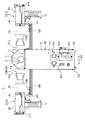
図1は、本発明の一実施形態に係るシュリンク包装装置1を示す斜視図である。本実施形態に係るシュリンク包装装置1は、包装体5を予熱した後、この包装体5を本加熱して収縮させ、これにより、包装体5を本体6に密着させることができる。このシュリンク包装装置1は、小容量の電源(例えば100VAC)を用いて運転することができる。
[Overall structure of shrink wrapping equipment]
FIG. 1 is a perspective view showing a
シュリンク包装装置1では、包装体5の予熱工程及び本加熱工程は自動で行われ、シュリンク包装装置1に包装体5及び本体6を供給する工程は手動で行われる。このように本実施形態のシュリンク包装装置1は、半自動の装置であるが、これに限られず、シュリンク包装装置1に包装体5及び本体6を供給する工程も自動で行われるように構成されていてもよい。
In the
包装体5及び本体6としては、種々のものを対象とすることができる。包装体5は熱収縮性を有するものであればよく、例えばポリエチレン、ポリプロピレン、ポリ塩化ビニル、ポリスチレン、ポリエステルなどの種々の材料を用いることができる。以下では、本体6としての容器に包装体5としてのラベルを固定するという具体例を挙げて説明するが、包装体5及び本体6の対象はこれらに限られるものではない。
As the
図1〜図5に示すように、本実施形態に係るシュリンク包装装置1は、搬送機構2と、送風機構3と、カバー部材4と、フレーム10とを備える。
As shown in FIGS. 1 to 5, the
フレーム10は、搬送機構2、送風機構3、カバー部材4などを支持する機能を有する。フレーム10は、例えば、一対の上部フレーム101と、一対の下部フレーム102と、複数の側部フレーム103と、正面パネル104と、背面パネル105と、送風機支持フレーム106とを備え、全体として略直方体形状の枠体を構成しているが、このような構成に限られない。
The
一対の上部フレーム101は、包装体5及び本体6の搬送方向D1に延びており、幅方向D2(搬送方向D1に直交し水平方向に平行な方向D2)に互いに間隔をあけて配置されている。一対の下部フレーム102は、上部フレーム101の下方において、搬送方向D1に延びており、幅方向D2に互いに間隔をあけて配置されている。
The pair of
各側部フレーム103は、上下方向に延びている。複数の側部フレーム103のうち、右側に設けられた2つの側部フレーム103は、右側の上部フレーム101と右側の下部フレーム102とに固定されており、左側に設けられた2つの側部フレーム103は、左側の上部フレーム101と左側の下部フレーム102とに固定されている。
Each
正面パネル104は、搬送方向D1の上流側に設けられた2つの側部フレーム103に固定されている。背面パネル105は、搬送方向D1の下流側に設けられた2つの側部フレーム103に固定されている。正面パネル104には、シュリンク包装装置1の主電源をオン・オフするスイッチ201、搬送機構2をオン・オフするスイッチ202、搬送機構2の速度調節ツマミ203、送風機構3のヒータ35の温度調節ツマミ204などが設けられている。温度調節ツマミ204は、後述する第1送風機31のヒータ35と第2送風機32のヒータ35とを個別に温度調節可能である。
The
[搬送機構]
搬送機構2は、包装体5を予熱する予熱位置P1及び包装体5を本加熱する本加熱位置P2の順に包装体5及び本体6を搬送方向D1に搬送する機能を有する。図1〜図5に示すように、搬送機構2は、搬送ベルト20と、搬送ベルト20と支持する複数のローラと、複数のローラの少なくとも1つを駆動する図略の搬送モータとを備える。
[Transport mechanism]
The
本実施形態では、搬送ベルト20は、環状経路を有する無端ベルトである。搬送ベルト20は、複数の上部ローラ21,22と、複数の下部ローラ23,24とによって支持されている。前記搬送モータが回転することによって複数のローラ21〜24の少なくとも1つのローラが回転し、これにより、搬送ベルト20が環状経路に沿って回転する。
In the present embodiment, the
上部ローラ21は、搬送方向D1の上流側において正面パネル104の近傍に配置され、例えば一対の側部フレーム103に回転可能に支持されている。上部ローラ22は、搬送方向D1の下流側において背面パネル105の近傍に配置され、例えば一対の側部フレーム103に回転可能に支持されている。本実施形態では、上部ローラ21,22は、包装体5及び本体6が搬送される搬送路20Pが水平になるように互いに同じ高さに配置されているが、これに限られず、異なる高さに配置されていてもよい。
The
下部ローラ23は、上部ローラ22の下方において背面パネル105の近傍に配置され、例えば一対の側部フレーム103に回転可能に支持されている。下部ローラ23は、フレーム10(具体的には側部フレーム103)に対して移動可能なようにフレーム10に取り付けられている。具体的に、下部ローラ23は、軸方向の一方又は両方にテンション調節機構23aを有している。テンション調節機構23aは、下部ローラ23をフレーム10に対して移動(具体的には上下移動)させることによって搬送ベルト20のテンションを調整するように構成されている。ローラ23における両側の軸は、側部フレーム103に設けられた長孔103aに挿通されており、テンション調節機構23aは、ローラ23における前記軸の端部に取り付けられたナット状の部材と、この部材に螺合されたねじ部材とを有している。このねじ部材を回転させることによってローラ23が上下に移動し、これにより、搬送ベルト20のテンションを調節することができる。
The
下部ローラ24は、下部ローラ23よりも正面パネル104側に配置され、例えば一対の下部フレーム102に回転可能に支持されている。下部ローラ23,24は、搬送ベルト20の環状経路の内側に後述する第2送風機32を配置することができる程度に上部ローラ21,22に対して下方に間隔をあけて配置されている。
The
搬送ベルト20のうち、一対の上部ローラ21,22に支持された部分が、包装体5及び本体6を搬送する搬送路20Pとして機能する。本実施形態では、搬送ベルト20の搬送路20Pは、水平面に対してほぼ平行な姿勢で設けられているが、これに限られず、水平面に対して傾斜していてもよい。
A portion of the
図6に示すように、本実施形態では、搬送ベルト20は、多数の貫通孔20aを有するメッシュベルトである。多数の貫通孔20aは、搬送方向D1に並ぶとともに、幅方向D2にも並んでおり、搬送ベルト20の全体にわたってほぼ均一に配列されている。本実施形態では、各貫通孔20aは、四角形状であるが、これに限られず、例えば円形状などであってもよい。また、多数の貫通孔20aは、ほぼ同じ大きさを有しているが、これに限られない。
As shown in FIG. 6, in this embodiment, the
[送風機構]
送風機構3は、本加熱位置P2に温風を噴出する機能を有する。図1〜図5に示すように、本実施形態では、送風機構3は、第1送風機31と第2送風機32とを備える。第1送風機31及び第2送風機32は、互いに異なる方向から本加熱位置P2に向けて温風を噴出するように配置されている。具体的に、第1送風機31は、搬送ベルト20の上方に配置されており、温風を本加熱位置P2に向けて下方に噴出し、第2送風機32は、搬送ベルト20の環状経路の内側に配置されており、温風を本加熱位置P2に向けて上方に噴出する。
[Blower mechanism]
The
図2に示すように、第1送風機31は、第1支持部材107を介して送風機支持フレーム106に支持されており、第2送風機32は、第2支持部材107を介して送風機支持フレーム106に支持されている。送風機支持フレーム106は、上下方向に延びる細長い形状を有する。
As shown in FIG. 2, the
第1送風機31は、第1筐体33内に第1ファン34と第1ヒータ35とが内蔵された一体型のコンパクトな構造を有している。第1筐体33の先端部には第1噴出口31aが設けられており、先端部とは反対側の基端部には第1吸込口31bが設けられている。第2送風機32は、第2筐体33内に第2ファン34と第2ヒータ35とが内蔵された一体型のコンパクトな構造を有し、第2筐体33の先端部には第2噴出口32aが設けられており、先端部とは反対側の基端部には第2吸込口32bが設けられている。第1噴出口31aと第2噴出口32aは、搬送ベルト20の一部分である搬送路20Pを介して上下方向に対向している。
The
第1送風機31及び第2送風機32のそれぞれにおいて、ファン34が駆動されると、吸込口31b,32bから筐体33内に吸い込まれた空気は、ヒータ35によって加熱され、噴出口31a,32aから温風としてそれぞれ噴出される。
In each of the
本実施形態では、第1送風機31及び第2送風機32のそれぞれにおいて、筐体33の先端部は扁平な形状を有しており、噴出口31a,32aは、細長いスリット状の開口形状を有している。本実施形態では、噴出口31a,32aの長手方向は幅方向D2に向いているが、これに限られない。噴出口31a,32aが幅方向D2に長いスリット状の開口形状を有している場合には、幅方向D2の広い範囲に温風を噴出させることができるとともに、温風の噴出速度を高めることができる。
In the present embodiment, in each of the
第1送風機31及び第2送風機32は、上下方向の位置を調節することができるように構成されている。図2に示すように、送風機支持フレーム106は、長手方向に沿って設けられたレール部106aと、第1支持部材107及び第2支持部材107のそれぞれを送風機支持フレーム106に固定する固定部材106b(例えばねじ)とを有する。各支持部材107は、固定部材106bによる固定状態が解除されると、レール部106aに沿って上下方向にスライド移動可能となり、固定部材106bによって固定状態とされると、送風機支持フレーム106に固定される。したがって、第1送風機31及び第2送風機32は、上下方向の位置を調節することができる。
The
また、第1送風機31及び第2送風機32は、温風の噴出方向を調節することができるように構成されている。図3に示すように、各支持部材107は、円弧状の長孔107aと、対応する送風機31,32を支持部材107に固定する固定部材107b(例えばねじ)とを有する。各送風機31,32は、支点107cを中心に回動可能に支持部材107に取り付けられている。各送風機31,32は、固定部材107bによる固定状態が解除されると、支点107cを中心として長孔107aの範囲内で長孔107aに沿って回動可能となり、固定部材107bによって固定状態とされると、支持部材107に固定される。
Moreover, the
例えば図7に示すように、第1送風機31は、噴出口31aから噴出される温風の噴出方向(図7における直線L1の方向)を、搬送方向D1に直交する平面Pに対して予熱位置P1側に傾斜する方向に調節することができる。また、第2送風機32は、第1送風機31と同様に、噴出口32aから噴出される温風の噴出方向を、搬送方向D1に直交する平面Pに対して予熱位置P1側に傾斜する方向に調節することができる。なお、図3に示す状態では、第1送風機31の噴出口31aから噴出される温風の噴出方向L1は、平面Pと平行な方向に向いている。
For example, as shown in FIG. 7, the
なお、本実施形態では、第1送風機31及び第2送風機32が後述するカバー部材4の先端部4E2よりも下流側に配置されているので、第1送風機31及び第2送風機32の角度を調節しやすい構造である。
In the present embodiment, since the
[カバー部材]
カバー部材4は、送風機構3から本加熱位置P2に噴出されて上流側の予熱位置P1に流れた温風が予熱位置P1において周囲に拡散するのを抑制する機能を有する。図1〜図5に示すように、カバー部材4は、搬送ベルト20の搬送路20Pの一部を覆うように設けられている。カバー部材4は、予熱位置P1の両側方と上方とを塞ぐトンネル状の形状を有している。カバー部材4は、搬送方向D1の上流側の基端部4E1と、搬送方向D1の下流側の先端部4E2とを有する。カバー部材4は、先端部4E2において途切れており、先端部4E2よりも下流側には設けられていない。
[Cover member]
The
図1及び図8に示すように、本実施形態では、カバー部材4は、一対の側壁部41,42と、上壁部43とを有する。各側壁部41,42は、搬送方向D1に延びる形状を有する。一方の側壁部41(右側壁部41)は、予熱位置P1の右側を塞いでおり、他方の側壁部42(左側壁部42)は、予熱位置P1の左側を塞いでいる。上壁部43は、搬送方向D1に延びる形状を有し、予熱位置P1の上方を塞いでいる。
As shown in FIGS. 1 and 8, in this embodiment, the
右側壁部41は、右側の第1フレーム101に支持されており、この第1フレーム101から上方に起立した姿勢で設けられている。左側壁部42は、左側の第1フレーム101に支持されており、この第1フレーム101から上方に起立した姿勢で設けられている。上壁部43は、側壁部41の上端と側壁部42の上端とを接続している。
The right
上壁部43は、水平面に平行な平板によって形成されていてもよいが、カバー部材4の内側空間の容積を小さくするために、例えば、アーチ状に湾曲した形状、折れ曲がった形状などであってもよい。このようにカバー部材4の内側空間の容積が小さくなることにより、温風によってカバー部材4の内側空間の温度を上昇させやすくなる。本実施形態では、上壁部43は、図1及び図8に示すように折れ曲がった形状を有している。すなわち、上壁部43は、搬送方向D1に延びて水平面に平行な中央部43aと、中央部43aの両サイドにそれぞれ設けられた傾斜部43b,43cとを有する。傾斜部43b,43cは、中央部43aから幅方向D2の外側にそれぞれ延びつつ、下方に傾斜している。傾斜部43b,43cの下端は、側壁部41,42の上端にそれぞれ接続されている。
The
本実施形態では、カバー部材4は、フレーム10に対する搬送方向D1の位置を調節することができるように構成されている。言い換えると、カバー部材4は、搬送機構2の搬送ベルト20及び送風機構3の送風機31,32に対する搬送方向D1の位置を調節することができるように構成されている。
In the present embodiment, the
図1〜図3に示すように、各第1フレーム101は、搬送方向D1の延びる長孔101aと、カバー部材4の側壁部41,42を第1フレーム101に固定する固定部材101b(例えばねじ)とを有する。カバー部材4は、固定部材101bによる固定状態が解除されると、長孔101aの範囲内で長孔101aに沿って搬送方向D1にスライド移動可能となり、固定部材101bによって固定状態とされると、第1フレーム101に固定される。
As shown in FIGS. 1 to 3, each
また、本実施形態では、カバー部材4は、フレーム10に対する上下方向の位置を調節することができるように構成されている。言い換えると、カバー部材4は、カバー部材4の内側空間の高さを調節することができるように構成されている。
In the present embodiment, the
図1〜図3に示すように、側壁部41は、上下方向に延びる長孔41aを有し、側壁部42は、上下方向に延びる長孔42aを有している。長孔41a,42aには上述した固定部材101bが係合している。カバー部材4は、固定部材101bによる固定状態が解除されると、長孔41a,42aの範囲内で長孔41a,42aに沿って上下方向にスライド移動可能となり、固定部材101bによって固定状態とされると、第1フレーム101に固定される。
As shown in FIGS. 1-3, the
[案内部材]
本実施形態では、カバー部材4の先端部4E2よりも下流側に本加熱位置P2が設けられているので、本加熱位置P2に噴出された温風は四方に拡散しやすい。そこで、図1〜図3に示すように、本実施形態では、シュリンク包装装置1は一対の案内部材7を備えている。一対の案内部材7は、本加熱位置P2に噴出された温風をカバー部材4の内側に案内する機能を有する。これにより、案内部材7が設けられていない場合に比べて、送風機構3から本加熱位置P2に噴出された温風のうちの予熱位置P1に流れる温風の割合を増加させることができる。
[Guide member]
In the present embodiment, since the main heating position P2 is provided on the downstream side of the front end portion 4E2 of the
図1及び図2に示すように、一方の案内部材7(右側の案内部材7)は、カバー部材4における右側の側壁部41に接続されており、右側の側壁部41の先端部4E2から搬送方向D1に延出している。また、図1及び図3に示すように、他方の案内部材7(左側の案内部材7)は、カバー部材4における左側の側壁部42に接続されており、左側の側壁部41の先端部4E2から搬送方向D1に延出している。一対の案内部材7,7の間の領域は上方が開口しており、塞がれていない。
As shown in FIGS. 1 and 2, one guide member 7 (right guide member 7) is connected to the right
[閉塞部材]
図5及び図8に示すように、本実施形態では、予熱位置P1の下方は、予熱位置P1にある搬送ベルト20の下方に設けられた閉塞部材9によって塞がれている。このように多数の貫通孔20aを有する搬送ベルト20の下方に閉塞部材9が設けられているので、予熱位置P1においては、その両側方、上方及び下方がカバー部材4と閉塞部材9によって囲まれることになる。これにより、予熱位置P1において両側方、上方及び下方への温風の拡散がカバー部材4と閉塞部材9によって抑制されるので、予熱位置P1において包装体5を予熱する熱量をより確実に確保することができる。
[Occlusion member]
As shown in FIGS. 5 and 8, in the present embodiment, the lower part of the preheating position P1 is closed by the closing
本実施形態では、閉塞部材9は、図5において破線で四角に囲まれた領域に設けられた平板状の部材である。閉塞部材9は、搬送ベルト20と同程度の幅(カバー部材4と同程度の幅)を有し、カバー部材4の搬送方向D1の長さと同程度の長さを有しているが、これに限られない。閉塞部材9は、カバー部材4の幅及び長さよりも小さくてもよい。なお、閉塞部材9は、例えば固定部材101bによってカバー部材4に固定されており、これにより、カバー部材4が上述したように搬送方向D1にスライド移動するときには、カバー部材4とともに移動するように構成されている。
In the present embodiment, the closing
なお、閉塞部材9は、カバー部材4の下方に設けられている一方で、カバー部材4の先端部4E2よりも下流側には設けられていない。すなわち、閉塞部材9は、本加熱位置P2には設けられていない。
The closing
[予熱位置、本加熱位置]
図1〜図5及び図8に示すように、本実施形態では、予熱位置P1は、本加熱位置P2よりも搬送方向D1の上流側であって、カバー部材4と搬送ベルト20の搬送路20Pに囲まれた領域である。予熱位置P1は、図5に示すようにシュリンク包装装置1を平面視したときに、搬送方向D1の長さと、幅方向D2の長さとを有し、図8に示すように搬送路20Pからカバー部材4の内面までの高さを有する。
[Preheating position, main heating position]
As shown in FIGS. 1 to 5 and 8, in the present embodiment, the preheating position P <b> 1 is upstream of the main heating position P <b> 2 in the transport direction D <b> 1, and the
図1〜図3及び図9に示すように、本実施形態では、本加熱位置P2は、送風機構3から噴出される温風が包装体5に当たる位置である。本加熱位置P2は、送風機構3から温風が噴出される方向に送風機構3から直線を引いたときに、この直線と包装体5とが交わる位置である。具体的には、図2、図3及び図9に示すように、第1送風機31から噴出される温風が包装体5に当たる本加熱位置P2は、第1送風機31の第1噴出口31aの中心を通る直線L1上にある。また、第2送風機32から噴出される温風が包装体5に当たる本加熱位置P2は、第2送風機32の第2噴出口32aの中心を通る直線L2上にある。
As shown in FIG. 1 to FIG. 3 and FIG. 9, in the present embodiment, the main heating position P <b> 2 is a position where hot air blown from the
例えば図3に示す状態から図7に示す状態に、噴出口31aから噴出される温風の噴出方向を予熱位置P1側に傾斜する方向に調節した場合には、本加熱位置P2は、傾斜した分だけ予熱位置P1側に移動する。
For example, when the direction of warm air ejected from the
本実施形態では、本加熱位置P2は、カバー部材4が途切れた位置(すなわちカバー部材4の先端部4E2)よりも搬送方向D1の下流側に位置している。第1送風機31から温風が噴出される本加熱位置P2の上方は開口しており、カバー部材4のようなカバーは設けられていない。同様に、第2送風機32から温風が噴出される本加熱位置P2の下方は開口しており、カバー部材4のようなカバーは設けられていない。本実施形態では、包装体5及び本体6がカバー部材4の内側空間を通過した直後に包装体5が本加熱されるように、本加熱位置P2はカバー部材4の先端部4E2の近傍に(カバー部材4によるトンネルを出たすぐのところ)に設けられている。
In the present embodiment, the main heating position P2 is located on the downstream side in the transport direction D1 from the position where the
なお、本実施形態では、噴出方向L1を平面Pと平行な方向に向けた図3に示す状態、及び噴出方向L1を予熱位置P1側に傾斜させた図7に示す状態の何れの状態においても、送風機31の噴出口31aの位置は、搬送方向D1において、カバー部材4が途切れたところよりも下流側(すなわち、カバー部材4の先端部4E2よりも下流側)に位置している。これにより、本加熱位置P2に噴出されて包装体5を収縮させた温風が周囲に拡散しやすくなる。したがって、本加熱位置P2において包装体5に当たる温風によって包装体5の温度を一時的に(瞬間的に)上昇させつつ、包装体5に対して必要以上の熱量が加えられるのを抑制することができる。
In this embodiment, in any state of the state shown in FIG. 3 in which the ejection direction L1 is directed in a direction parallel to the plane P and the state shown in FIG. 7 in which the ejection direction L1 is inclined toward the preheating position P1. The position of the
[動作]
次に、シュリンク包装装置1の動作について説明する。シュリンク包装装置1の主電源がオンにされ、搬送機構2の運転が開始されると、搬送ベルト20が環状経路に沿って移動し始める。包装する対象(包装体5及び本体6)が複数ある場合には、搬送ベルト20は連続して運転される。搬送ベルト20の速度は必要に応じて調節される。
[Operation]
Next, the operation of the
また、送風機構3の第1送風機31及び第2送風機32の送風が開始されるとともに、必要に応じてヒータ35の温度が調節される。また、必要に応じて、第1送風機31及び第2送風機32の温風の噴出方向が調節される。包装する対象(包装体5及び本体6)が複数ある場合には、第1送風機31及び第2送風機32からの温風の噴出は連続して行われる。
Moreover, while the ventilation of the
図2及び図3に示すように、第1送風機31の第1噴出口31aから噴出方向L1(直線L1の方向)に温風が吹き出されると、その温風の一部は、案内部材7に案内されてカバー部材4の内側に流れ込む。流れ込んだ温風は、カバー部材4及び閉塞部材9によって周囲への拡散が抑制されるので、カバー部材4の内側空間(すなわち予熱位置P1)の温度を上昇させる。
As shown in FIGS. 2 and 3, when warm air is blown out from the
この状態で、本体6とこれに仮取り付けされた包装体5が搬送ベルト20の搬送路20Pの上流側端部あたりに載置される。載置された包装体5及び本体6は、搬送ベルト20の搬送路20P上を搬送方向D1の下流側に移動し、カバー部材4の内側空間(すなわち予熱位置P1)に到達する。予熱位置P1に到達した包装体5及び本体6は、カバー部材4の内側空間を移動する間、その周りの暖かい空気によって予備的に加熱される。
In this state, the
そして、包装体5及び本体6がさらに搬送方向D1に移動し、カバー部材4の外に出ると、その直後に包装体5が本加熱位置P2に到達する。本加熱位置P2では、第1送風機31の第1噴出口31aから噴出される温風と、第2送風機32の第2噴出口32aから噴出される温風とが包装体5に直に当たるので、包装体5の温度は、熱収縮する温度以上に急速に上昇する。これにより、包装体5は、本加熱位置P2において瞬時に熱収縮し、本体6に固定される。
And if the
このとき、搬送ベルト20は連続して移動しているので、包装体5は、熱収縮した後、本加熱位置P2から搬送方向D1の下流側にずれた位置に移動する。また、本実施形態では、本加熱位置P2及び本加熱位置P2よりも下流側にはカバーが設けられていないので、包装体5は、熱収縮した後、周囲の空気によって急速に冷却される。これにより、包装体5に余分な熱が加えられるのを抑制できる。以下、他の包装体5及び本体6についても同様にして予熱及び本加熱が行われる。
At this time, since the
なお、シュリンク包装装置1は、小容量の電源(例えば100VAC)を用いて運転することができる。具体例を挙げると次のようになる。送風機構3(第1送風機31と第2送風機32)に要する電力は合計で、例えば1400W以下に設定され、具体的には例えば1300〜1400W程度に設定される。また、搬送機構2に要する電力は、例えば20W以下に設定され、具体的には例えば10〜20W程度に設定される。そして、本実施形態のシュリンク包装装置1は、1500W以下での運転が可能である。
In addition, the
[変形例1]
図10は、シュリンク包装装置1の変形例1を示す断面図である。変形例1では、カバー部材4の内側に1つ又は複数の乱流部材8が設けられている。図10に示す具体例では、複数の乱流部材8が設けられている。乱流部材8は、カバー部材4内の温風の流れを乱す機能を有する。
[Modification 1]
FIG. 10 is a cross-sectional view illustrating a first modification of the
この変形例1では、本加熱位置P2に噴出されてカバー部材4内に流入した温風の流れがカバー部材4の内側空間において乱流部材8によって乱されるので、カバー部材4内において温度の均一化を図ることができ、また、温風がカバー部材4の内側空間に滞留する時間を延ばすことができる。これにより、本加熱位置P2に噴出されてカバー部材4内に流入した温風をより効率よく予熱に用いることができる。
In the first modification, the flow of the warm air that has been ejected to the main heating position P2 and has flowed into the
図10に示す具体例では、各乱流部材8は、カバー部材4の内面に取り付けられた板状部材(邪魔板)であるが、乱流部材8の構造はこれに限られない。乱流部材8は、カバー部材4の内側空間(トンネル内)において空気の渦をつくるような羽根や弁などによって構成されていてもよい。
In the specific example shown in FIG. 10, each
[変形例2]
図11は、シュリンク包装装置1の変形例2を示す正面図であり、図12は、シュリンク包装装置1の変形例2を示す平面図である。図11及び図12に示すように、この変形例2のシュリンク包装装置1は、第1送風機31及び第2送風機32の配置が図1〜図5に示した実施形態と異なっており、それ以外の構成は図1〜図5に示した実施形態と同じである。
[Modification 2]
FIG. 11 is a front view showing a second modification of the
この変形例2では、送風機構3は、包装体5に対して側方から温風を当てるように構成されている。具体的に、第1送風機31及び第2送風機32は、搬送ベルト20の搬送路20Pの両サイドに配置されている。第1送風機31は、搬送路20Pの右側に配置され、第2送風機32は、搬送路20Pの左側に配置されている。
In the second modification, the
この変形例2においても、本加熱位置P2は、カバー部材4が途切れたところ(すなわちカバー部材4の先端部4E2)よりも下流側に設けられている。本加熱位置P2は、送風機構3から噴出される温風が包装体5に当たる位置である。具体的には、図11及び図12に示すように、第1送風機31から噴出される温風が包装体5に当たる本加熱位置P2は、第1送風機31の第1噴出口31aの中心を通る直線L1上にある。また、第2送風機32から噴出される温風が包装体5に当たる本加熱位置P2は、第2送風機32の第2噴出口32aの中心を通る直線L2上にある。
Also in the second modification, the main heating position P2 is provided on the downstream side of the place where the
第1送風機31及び第2送風機32から温風が噴出される本加熱位置P2の上方は開口しており、カバー部材4のようなカバーは設けられていない。包装体5及び本体6がカバー部材4の内側空間を通過した直後に包装体5が本加熱されるように、本加熱位置P2はカバー部材4の先端部4E2の近傍に(カバー部材4によるトンネルを出たすぐのところ)に設けられている。
The upper part of the main heating position P <b> 2 where hot air is ejected from the
なお、この変形例2では、一対の案内部材7は、第1送風機31及び第2送風機32から噴出される温風が本加熱位置P2に到達するうえで邪魔にならない位置に設けられている。図11及び図12に示す変形例2では、案内部材7は、図1〜図3に示す実施形態と同様に、左右に設けられている。すなわち、一方の案内部材7(右側の案内部材7)が、カバー部材4における右側の側壁部41の先端部4E2に接続されてそこから搬送方向D1に延出しており、他方の案内部材7(左側の案内部材7)が、カバー部材4における左側の側壁部42の先端部4E2に接続されてそこから搬送方向D1に延出しているが、これに限られない。変形例2では、案内部材7は、左右に設けられるのではなく、例えば上下に設けられていてもよい。具体的に、例えば、一方の案内部材7(上側の案内部材7)が、カバー部材4における上壁部43の先端部4E2に接続されてそこから搬送方向D1に延出し、他方の案内部材7(下側の案内部材7)が、上側の案内部材7よりも下方の位置であって上側の案内部材7に対して上下方向に対向する位置に設けられていてもよい。この下側の案内部材7は、例えば閉塞部材9の下流側端部に接続されてそこから搬送方向D1に延出する形態を例示することができる。
In the second modification, the pair of
[変形例3]
図13は、シュリンク包装装置1の変形例3を示す断面図である。この変形例3は、本加熱位置P2にもカバー部材が設けられている点で図1〜図5に示した実施形態と異なっており、それ以外の構成は図1〜図5に示した実施形態と同じである。
[Modification 3]
FIG. 13 is a cross-sectional
図13に示す変形例3では、カバー部材4は、搬送方向D1の上流側の基端部4E1と、搬送方向D1の下流側の先端部4E2とを有し、本加熱位置P2は、カバー部材4の先端部4E2よりも上流側に設けられている。カバー部材4は、本加熱位置P2に対応する位置に、第1噴出口31aが設けられた第1送風機31の先端部を挿入するための挿入口4aを有している。この挿入口4aは、第1送風機31の先端部と同じ大きさ又は第1送風機31の先端部よりも少し大きい孔である。
In
ただし、図13に示す変形例3では、図1〜図5に示す実施形態に比べて、送風機構3から本加熱位置P2噴出された温風が周囲に拡散しにくくなるので、包装体5が高温の雰囲気に長い時間晒されて、包装体5に必要以上の熱量が加えられる場合がある。
However, in the third modification shown in FIG. 13, the hot air jetted from the main heating position P <b> 2 from the
[実施形態のまとめ]
本実施形態では、包装体5の本加熱は、送風機構3から本加熱位置P2に噴出される温風によって行われる一方で、包装体5の予熱は、送風機構3から本加熱位置P2に噴出されて上流側の予熱位置P1に流れた温風によって行われる。すなわち、本実施形態では、本加熱に用いられた温風を予熱にも用いているので、従来のように本加熱用の温風を供給するためのファン及びヒータと予熱用の温風を供給するためのファン及びヒータとをそれぞれ設ける場合に比べて、消費電力を低減することができる。しかも、本実施形態では、本加熱位置P2に噴出された温風の一部が上流側に流れ、当該温風が予熱位置P1において周囲に拡散することがカバー部材4によって抑制されるので、予熱位置P1において包装体5を予熱する熱量を確保することができる。したがって、本構成のシュリンク包装装置1は、包装体5を予熱した後、この包装体5を本加熱して収縮させ、これにより、包装体5を本体6に固定することができ、しかも、小容量の電源を用いて運転することができる。
[Summary of Embodiment]
In the present embodiment, the main heating of the
シュリンク包装装置1において、本加熱位置P2は、カバー部材4が途切れたところよりも下流側に設けられているのが好ましい。本加熱位置P2において送風機構3から噴出される温風が包装体5に当たると、包装体5は急速に加熱される。ここで、熱収縮する包装体5は、その温度が熱収縮する温度以上に一時的に(瞬間的に)達すればよい。包装体5が高温の雰囲気に長い時間晒されると、包装体5に必要以上の熱量が加えられることになり、場合によっては不具合(例えば包装体5に孔があくなどの不具合)が生じることがある。一方、カバー部材4が途切れたところよりも下流側に本加熱位置P2が設けられている構成では、カバー部材4が本加熱位置P2にも設けられている場合に比べて、本加熱位置P2に噴出されて包装体5を収縮させた温風が周囲に拡散しやすくなる。したがって、この構成では、本加熱位置P2において包装体5に当たる温風によって包装体5の温度を一時的に(瞬間的に)上昇させつつ、包装体5に対して必要以上の熱量が加えられるのを抑制することができるので、包装体5に上記のような不具合が生じるのを抑制できる。
In the
シュリンク包装装置1において、本加熱位置P2に噴出された温風をカバー部材4の内側に案内する案内部材7を備えているのが好ましい。この構成では、案内部材7が設けられていない場合に比べて、送風機構3から本加熱位置P2に噴出された温風のうちの予熱位置P1に流れる温風の割合を増加させることができる。これにより、包装体5をより効率よく予熱することができる。
The
シュリンク包装装置1において、送風機構3は、搬送方向に直交する平面に対して予熱位置P1側に傾斜した方向に向けて温風を本加熱位置P2に噴出するように構成されていてもよい。又は、送風機構3は、温風を噴出する方向が調節可能に構成されていてもよい。この構成のように本加熱位置P2に噴出される温風の向きが予熱位置P1側に傾斜した方向である場合には、送風機構3から本加熱位置P2に噴出された温風のうちの多くを予熱位置P1側に流すことができる。これにより、包装体5をさらに効率よく予熱することができる。また、送風機構3が、温風を噴出する方向が調節可能に構成されている場合には、送風機構3から噴出される温風の噴出方向を予熱位置P1側に調節することによって、送風機構3から本加熱位置P2に噴出された温風のうちの多くを予熱位置P1側に流すことができる。これにより、包装体5をさらに効率よく予熱することができる。
In the
シュリンク包装装置1において、カバー部材4の内側には、カバー部材4内の温風の流れを乱す乱流部材8が設けられていてもよい。この構成では、本加熱位置P2に噴出されてカバー部材4内に流入した温風の流れがカバー部材4内において乱流部材によって乱されるので、カバー部材4内において温度の均一化を図ることができ、また、温風がカバー部材4内に滞留する時間を延ばすことができる。これにより、本加熱位置P2に噴出されてカバー部材4内に流入した温風をより効率よく予熱に用いることができる。
In the
シュリンク包装装置1において、搬送機構は、包装体5及び本体6が載置された状態で予熱位置P1及び本加熱位置P2の順に移動する搬送ベルト20を備え、搬送ベルト20は多数の貫通孔20aを有しているのが好ましい。この構成では、搬送ベルト20が多数の貫通孔を有しているので、送風機構3から噴出された温風を搬送ベルト20の貫通孔を通過させて、搬送ベルト20上に載置された包装体5及び本体6に当てることもできるようになる。例えば、この構成では、搬送ベルト20の下方から搬送ベルト20に向かって噴出された温風は、貫通孔を通過して搬送ベルト20上に載置された包装体5及び本体6に当たる。
In the
シュリンク包装装置1において、カバー部材4は、予熱位置P1の両側方と上方とを塞ぐトンネル状の形状を有し、予熱位置P1の下方は、予熱位置P1にある搬送ベルト20の下方に設けられた閉塞部材9によって塞がれているのが好ましい。この構成では、搬送ベルト20が多数の貫通孔20aを有していても、その搬送ベルト20の下方に閉塞部材9が設けられているので、予熱位置P1においては、その両側方、上方及び下方がカバー部材4と閉塞部材9によって囲まれることになる。これにより、予熱位置P1において両側方、上方及び下方への温風の拡散がカバー部材4と閉塞部材9によって抑制されるので、予熱位置P1において包装体5を予熱する熱量をより確実に確保することができる。
In the
シュリンク包装装置1において、送風機構3は、本加熱位置P2に温風をそれぞれ噴出する第1噴出口31a及び第2噴出口32aを備え、第1噴出口31aと第2噴出口32aは、搬送ベルト20の一部分を介して対向しているのが好ましい。この構成では、搬送ベルト20が多数の貫通孔20aを有している場合において、その搬送ベルト20を介して対向する第1噴出口31aと第2噴出口32aのそれぞれから本加熱位置P2に温風が噴出される。これにより、包装体5に対して一方向のみから温風を噴出する場合に比べて、包装体5のより広範囲に温風を当てることができる。
In the
シュリンク包装装置1において、搬送ベルト20は、環状経路を有する無端ベルトであり、第1噴出口31aは、無端ベルトの上方に配置されており、第2噴出口32aは、無端ベルトの環状経路の内側に配置されているのが好ましい。この構成では、搬送ベルト20を介して対向する第1噴出口31aと第2噴出口32aのそれぞれから本加熱位置P2に温風が噴出される場合において、第2噴出口32aが無端ベルトの環状経路の内側に配置されているので、第2噴出口32aから噴出される温風を、搬送ベルト20上の包装体5に効率よく当てることができる。
In the
シュリンク包装装置1において、送風機構3は、第1筐体33内に第1ファン34と第1ヒータ35とが内蔵されるとともに第1筐体33の先端部に第1噴出口31aを有する第1送風機31と、第2筐体33内に第2ファン34と第2ヒータ35とが内蔵されるとともに第2筐体33の先端部に第2噴出口32aを有する第2送風機32と、を備えているのが好ましい。この構成では、送風機構3の第1送風機31及び第2送風機32のそれぞれは、ファン34とヒータ35とが筐体33内に内蔵され、この筐体33の先端部に噴出口31a,32aを有する構造である。このようにファン34とヒータ35とが筐体33内に内蔵されたコンパクトな構造であるとともに、ファン34と噴出口31a,32aとが近い位置にあるので少ない電力で効率よく温風を噴出させることができる。
In the
[その他の変形例]
以上、本発明の実施形態について説明したが、本発明はこれらの実施形態に限定されるものではなく、その趣旨を逸脱しない範囲で種々変更、改良等が可能である。
[Other variations]
As mentioned above, although embodiment of this invention was described, this invention is not limited to these embodiment, A various change, improvement, etc. are possible in the range which does not deviate from the meaning.
例えば、前記実施形態では、案内部材7が設けられている場合を例に挙げて説明したが、案内部材7は省略することもできる。
For example, in the embodiment, the case where the
前記実施形態では、搬送ベルト20が多数の貫通孔20aを有する場合を例に挙げて説明したが、搬送ベルト20は貫通孔20aを有していなくてもよい。
In the above-described embodiment, the case where the
前記実施形態では、予熱位置P1の下方が搬送ベルト20の下方に設けられた閉塞部材9によって塞がれている場合を例に挙げて説明したが、閉塞部材9は省略することもできる。
In the above-described embodiment, the case where the lower portion of the preheating position P1 is blocked by the closing
前記実施形態では、送風機構3が、筐体33内にファン34とヒータ35とが内蔵された一体型の送風機を備える場合を例に挙げて説明したが、ファン34とヒータ35とは別々の筐体に内蔵されていてもよい。
In the above-described embodiment, the case where the
前記実施形態では、2つの送風機31,32を設ける場合を例示したが、例えば4つの送風機を設けて、上下左右の4方向から包装体5に温風を噴出させる構成であってもよい。また、包装体5が小さい場合などには、1つの送風機31のみを設けるだけでもよい。
In the embodiment, the case where the two
前記実施形態では、送風機構3が、温風を噴出する方向が調節可能に構成されている場合を例に挙げて説明したが、送風機構3からの温風の噴出方向は調節可能でなく固定されていてもよい。この場合、例えば、送風機構3は、搬送方向D1に直交する平面Pに対して予熱位置P1側に傾斜した方向に向けて温風を本加熱位置P2に噴出するように固定されていてもよく、また、送風機構3は、搬送方向D1に直交する平面Pに平行な方向に向けて温風を本加熱位置P2に噴出するように固定されていてもよい。
In the above embodiment, the case where the
また、カバー部材4の上流側には、例えばのれん状のカーテンを取り付けてもよい。このようなカーテンをカバー部材4の上流側に取り付けることにより、温風がカバー部材4内に滞留する時間をさらに延ばすことができる。これにより、本加熱位置P2に噴出されてカバー部材4内に流入した温風をより効率よく予熱に用いることができる。なお、上記のカーテンは、例えばカバー部材4の上流側の基端部4E1から下方に垂れるような状態で基端部4E1に取り付けられる形態を例示できるが、これに限られない。
In addition, a funnel-shaped curtain may be attached to the upstream side of the
また、図1〜図3に示す実施形態では、案内部材7が側壁部41の先端部4E2に接続されてそこから搬送方向D1に延出する場合を例示したが、これに限られない。例えば図14に示す変形例4のように、案内部材7が上壁部43の一部(図例では上壁部43の傾斜部43b,43c)の先端部4E2に接続されてそこから搬送方向D1に延出するような形態であってもよい。すなわち、図14に示す変形例4では、案内部材7は、側壁部41の先端部4E2と上壁部43の一部の先端部4E2に接続されてそこから搬送方向D1に延出している。ただし、この変形例4においても、一対の案内部材7,7の間の領域は上方が開口しており、塞がれていない。
In the embodiment shown in FIGS. 1 to 3, the case where the
1 シュリンク包装装置
2 搬送機構
3 送風機構
4 カバー部材
5 包装体
6 本体
7 案内部材
8 乱流部材
9 閉塞部材
20 搬送ベルト
20a 貫通孔
31 第1送風機
31a 第1噴出口
32 第2送風機
32a 第2噴出口
33 筐体
34 ファン
35 ヒータ
P1 予熱位置
P2 本加熱位置
DESCRIPTION OF
Claims (9)
前記包装体を予熱する予熱位置及び前記包装体を本加熱する本加熱位置の順に前記包装体及び前記本体を搬送方向に搬送する搬送機構と、
前記本加熱位置に温風を噴出する送風機構と、
前記本加熱位置に噴出された前記温風を利用して前記包装体を予熱できるように、前記本加熱位置に噴出されて上流側の前記予熱位置に流れた前記温風が前記予熱位置において周囲に拡散するのを抑制するカバー部材と、を備え、
前記本加熱位置は、前記カバー部材が途切れたところよりも下流側に設けられている
シュリンク包装装置。 A shrink wrapping apparatus that heats the package so that the package that heat shrinks is fixed to the body,
A transport mechanism for transporting the package body and the main body in the transport direction in the order of a preheating position for preheating the package body and a main heating position for main heating the package body;
A blower mechanism for blowing warm air to the main heating position;
Wherein to allow preheating the package by using the warm air ejected to the heating position, around the warm air flowing in the preheating position upstream is injected into the main heating position at the preheating position and a suppressing cover member from diffusing into,
The main heating position is a shrink wrapping apparatus provided on the downstream side of the place where the cover member is interrupted .
請求項1に記載のシュリンク包装装置。 The shrink wrapping device according to claim 1, wherein the blower mechanism includes a blower in which a fan and a heater are built in a housing and has a spout at a tip portion .
前記包装体を予熱する予熱位置及び前記包装体を本加熱する本加熱位置の順に前記包装体及び前記本体を搬送方向に搬送する搬送機構と、
前記本加熱位置に温風を噴出する送風機構と、
前記本加熱位置に噴出された前記温風を利用して前記包装体を予熱できるように、前記本加熱位置に噴出されて上流側の前記予熱位置に流れた前記温風が前記予熱位置において周囲に拡散するのを抑制するカバー部材と、
前記本加熱位置に噴出された前記温風を前記カバー部材の内側に案内する案内部材と、を備える
シュリンク包装装置。 A shrink wrapping apparatus that heats the package so that the package that heat shrinks is fixed to the body,
A transport mechanism for transporting the package body and the main body in the transport direction in the order of a preheating position for preheating the package body and a main heating position for main heating the package body;
A blower mechanism for blowing warm air to the main heating position;
The warm air that has been ejected to the main heating position and has flowed to the preheating position on the upstream side is surrounded at the preheating position so that the package can be preheated using the warm air that has been ejected to the main heating position. A cover member that suppresses diffusion to
And a guide member for guiding the warm air ejected to the main heating positioned inside the cover member
Shrink wrapping device.
前記包装体を予熱する予熱位置及び前記包装体を本加熱する本加熱位置の順に前記包装体及び前記本体を搬送方向に搬送する搬送機構と、
前記本加熱位置に温風を噴出する送風機構と、
前記本加熱位置に噴出された前記温風を利用して前記包装体を予熱できるように、前記本加熱位置に噴出されて上流側の前記予熱位置に流れた前記温風が前記予熱位置において周囲に拡散するのを抑制するカバー部材と、を備え、
前記送風機構は、前記搬送方向に直交する平面に対して前記予熱位置側に傾斜した方向に向けて前記温風を前記本加熱位置に噴出するように構成されている、又は、前記温風を噴出する方向が調節可能に構成されている
シュリンク包装装置。 A shrink wrapping apparatus that heats the package so that the package that heat shrinks is fixed to the body,
A transport mechanism for transporting the package body and the main body in the transport direction in the order of a preheating position for preheating the package body and a main heating position for main heating the package body;
A blower mechanism for blowing warm air to the main heating position;
The warm air that has been ejected to the main heating position and has flowed to the preheating position on the upstream side is surrounded at the preheating position so that the package can be preheated using the warm air that has been ejected to the main heating position. A cover member that suppresses diffusion to
The air blowing mechanism is configured the warm air toward a direction inclined to the preheating position side with respect to a plane perpendicular to the conveying direction to eject the main heating position, or the hot air The jetting direction is adjustable .
Shrink wrapping device.
前記包装体を予熱する予熱位置及び前記包装体を本加熱する本加熱位置の順に前記包装体及び前記本体を搬送方向に搬送する搬送機構と、
前記本加熱位置に温風を噴出する送風機構と、
前記本加熱位置に噴出された前記温風を利用して前記包装体を予熱できるように、前記本加熱位置に噴出されて上流側の前記予熱位置に流れた前記温風が前記予熱位置において周囲に拡散するのを抑制するカバー部材と、を備え、
前記カバー部材の内側には、前記カバー部材内の前記温風の流れを乱す乱流部材が設けられている
シュリンク包装装置。 A shrink wrapping apparatus that heats the package so that the package that heat shrinks is fixed to the body,
A transport mechanism for transporting the package body and the main body in the transport direction in the order of a preheating position for preheating the package body and a main heating position for main heating the package body;
A blower mechanism for blowing warm air to the main heating position;
The warm air that has been ejected to the main heating position and has flowed to the preheating position on the upstream side is surrounded at the preheating position so that the package can be preheated using the warm air that has been ejected to the main heating position. A cover member that suppresses diffusion to
Inside of the cover member, turbulence member for disturbing the flow of the hot air in the cover member is provided
Shrink wrapping device.
前記包装体を予熱する予熱位置及び前記包装体を本加熱する本加熱位置の順に前記包装体及び前記本体を搬送方向に搬送する搬送機構と、
前記本加熱位置に温風を噴出する送風機構と、
前記本加熱位置に噴出された前記温風を利用して前記包装体を予熱できるように、前記本加熱位置に噴出されて上流側の前記予熱位置に流れた温風が前記予熱位置において周囲に拡散するのを抑制するカバー部材と、を備え、
前記搬送機構は、前記包装体及び前記本体が載置された状態で前記予熱位置及び前記本加熱位置の順に移動する搬送ベルトを備え、
前記搬送ベルトは多数の貫通孔を有し、
前記カバー部材は、前記予熱位置の両側方と上方とを塞ぐトンネル状の形状を有し、
前記予熱位置の下方は、前記予熱位置にある前記搬送ベルトの下方に設けられた閉塞部材によって塞がれている
シュリンク包装装置。 A shrink wrapping apparatus that heats the package so that the package that heat shrinks is fixed to the body,
A transport mechanism for transporting the package body and the main body in the transport direction in the order of a preheating position for preheating the package body and a main heating position for main heating the package body;
A blower mechanism for blowing warm air to the main heating position;
In order to preheat the package using the hot air blown to the main heating position, the hot air that has been blown to the main heating position and has flowed to the preheating position on the upstream side is surrounded by the preheating position. A cover member for suppressing diffusion,
The transport mechanism includes a transport belt that moves in the order of the preheating position and the main heating position in a state where the packaging body and the main body are placed.
The conveyor belt have a large number of through-holes,
The cover member has a tunnel-like shape that closes both sides and the upper side of the preheating position,
The lower part of the preheating position is blocked by a closing member provided below the conveying belt in the preheating position.
Shrink wrapping device.
前記第1噴出口と前記第2噴出口は、前記搬送ベルトの一部分を介して対向している
請求項6に記載のシュリンク包装装置。 The blower mechanism includes a first jet port and a second jet port that jet hot air to the main heating position, respectively.
The shrink packaging apparatus according to claim 6, wherein the first jet port and the second jet port are opposed to each other through a part of the transport belt .
第1筐体内に第1ファンと第1ヒータとが内蔵されるとともに先端部に前記第1噴出口を有する第1送風機と、 第2筐体内に第2ファンと第2ヒータとが内蔵されるとともに先端部に前記第2噴出口を有する第2送風機と、を備える
請求項7に記載のシュリンク包装装置。 The air blowing mechanism is
A first fan and a first heater are housed in the first housing and the first blower having the first jet outlet at the tip, and a second fan and a second heater are housed in the second housing. And a second blower having the second jet outlet at the tip.
The shrink wrapping apparatus according to claim 7 .
前記第1噴出口は、前記無端ベルトの上方に配置されており、
前記第2噴出口は、前記無端ベルトの前記環状経路の内側に配置されている
請求項7又は8に記載のシュリンク包装装置。 The conveyor belt is an endless belt having an annular path,
The first jet outlet is disposed above the endless belt,
The second jet nozzle is disposed inside the annular path of the endless belt.
The shrink wrapping apparatus according to claim 7 or 8 .
Priority Applications (1)
| Application Number | Priority Date | Filing Date | Title |
|---|---|---|---|
| JP2014050103A JP5965937B2 (en) | 2014-03-13 | 2014-03-13 | Shrink wrapping equipment |
Applications Claiming Priority (1)
| Application Number | Priority Date | Filing Date | Title |
|---|---|---|---|
| JP2014050103A JP5965937B2 (en) | 2014-03-13 | 2014-03-13 | Shrink wrapping equipment |
Publications (2)
| Publication Number | Publication Date |
|---|---|
| JP2015174666A JP2015174666A (en) | 2015-10-05 |
| JP5965937B2 true JP5965937B2 (en) | 2016-08-10 |
Family
ID=54254199
Family Applications (1)
| Application Number | Title | Priority Date | Filing Date |
|---|---|---|---|
| JP2014050103A Active JP5965937B2 (en) | 2014-03-13 | 2014-03-13 | Shrink wrapping equipment |
Country Status (1)
| Country | Link |
|---|---|
| JP (1) | JP5965937B2 (en) |
Families Citing this family (2)
| Publication number | Priority date | Publication date | Assignee | Title |
|---|---|---|---|---|
| JP6755166B2 (en) * | 2016-11-18 | 2020-09-16 | レンゴー株式会社 | Shrink wrapping mechanism and box wrapping equipment |
| CN114435648B (en) * | 2022-03-01 | 2023-03-24 | 擎安物流科技(溧阳)有限公司 | Recyclable packaging tool for battery packaging and transportation and using method thereof |
Family Cites Families (3)
| Publication number | Priority date | Publication date | Assignee | Title |
|---|---|---|---|---|
| JP3907436B2 (en) * | 2001-09-14 | 2007-04-18 | 日本テクノロジーソリューション株式会社 | Heating device |
| JP2003182709A (en) * | 2001-12-14 | 2003-07-03 | Toshiba Battery Co Ltd | Battery packaging device |
| JP5328426B2 (en) * | 2009-03-03 | 2013-10-30 | 東洋製罐株式会社 | Shrink device |
-
2014
- 2014-03-13 JP JP2014050103A patent/JP5965937B2/en active Active
Also Published As
| Publication number | Publication date |
|---|---|
| JP2015174666A (en) | 2015-10-05 |
Similar Documents
| Publication | Publication Date | Title |
|---|---|---|
| ES2230427T5 (en) | TUNNEL OVEN FOR THE MANUFACTURE OF THERMOCONTRAIBLE PLASTIC SHEET PACKAGING AND PACKAGING PROCEDURE AS EFFECTED. | |
| JP5674485B2 (en) | Method and apparatus for supporting and heating a glass sheet on a hot gas cushion | |
| US9517853B2 (en) | Apparatus for heat shrinking a film wrapping an object and method for operating the apparatus | |
| US5022165A (en) | Sterilization tunnel | |
| JP4791479B2 (en) | Conveyor for adjusting device used to position object in position | |
| US11549753B2 (en) | Laminar flow shrink oven | |
| EP2707197B1 (en) | Apparatus and method for heat shrinking a film wrapping an object | |
| JP5965937B2 (en) | Shrink wrapping equipment | |
| JP4709424B2 (en) | Printer | |
| CN105980129A (en) | Installation for thermally conditioning preforms with one portion of the preform being cooled by a blown curtain of air | |
| JP2020059274A (en) | Treatment machine for flexible long material, in particular plastic film, which is transported through treatment furnace | |
| JP3537703B2 (en) | Method and apparatus for shrinking shrink label | |
| JP3907436B2 (en) | Heating device | |
| JP2893064B2 (en) | Label shrinking method and device | |
| JP4382725B2 (en) | Food heating equipment | |
| BE1023137A9 (en) | Device for packaging a product in a shrink film. | |
| JP3923051B2 (en) | Drying equipment | |
| US6744976B1 (en) | Hot airflow generation device | |
| JP2023006800A (en) | Heat shrinkage device | |
| JP2010280409A (en) | Sealing apparatus | |
| JP3592033B2 (en) | Reflow soldering method and apparatus | |
| JP3442096B2 (en) | Reflow equipment | |
| JP6666935B2 (en) | Label heating device | |
| JP2017140774A (en) | Ink jet printer | |
| BR112020009480B1 (en) | THERMAL RETRACTION DEVICE IN SHRINK PACKAGING MACHINE |
Legal Events
| Date | Code | Title | Description |
|---|---|---|---|
| A621 | Written request for application examination |
Free format text: JAPANESE INTERMEDIATE CODE: A621 Effective date: 20150716 |
|
| A977 | Report on retrieval |
Free format text: JAPANESE INTERMEDIATE CODE: A971007 Effective date: 20160513 |
|
| A131 | Notification of reasons for refusal |
Free format text: JAPANESE INTERMEDIATE CODE: A131 Effective date: 20160524 |
|
| A521 | Request for written amendment filed |
Free format text: JAPANESE INTERMEDIATE CODE: A523 Effective date: 20160610 |
|
| TRDD | Decision of grant or rejection written | ||
| A01 | Written decision to grant a patent or to grant a registration (utility model) |
Free format text: JAPANESE INTERMEDIATE CODE: A01 Effective date: 20160628 |
|
| A61 | First payment of annual fees (during grant procedure) |
Free format text: JAPANESE INTERMEDIATE CODE: A61 Effective date: 20160704 |
|
| R150 | Certificate of patent or registration of utility model |
Ref document number: 5965937 Country of ref document: JP Free format text: JAPANESE INTERMEDIATE CODE: R150 |
|
| R250 | Receipt of annual fees |
Free format text: JAPANESE INTERMEDIATE CODE: R250 |
|
| R250 | Receipt of annual fees |
Free format text: JAPANESE INTERMEDIATE CODE: R250 |
|
| R250 | Receipt of annual fees |
Free format text: JAPANESE INTERMEDIATE CODE: R250 |
|
| R250 | Receipt of annual fees |
Free format text: JAPANESE INTERMEDIATE CODE: R250 |
|
| R250 | Receipt of annual fees |
Free format text: JAPANESE INTERMEDIATE CODE: R250 |
|
| R250 | Receipt of annual fees |
Free format text: JAPANESE INTERMEDIATE CODE: R250 |