JP5958005B2 - Front subframe structure of automobile - Google Patents
Front subframe structure of automobile Download PDFInfo
- Publication number
- JP5958005B2 JP5958005B2 JP2012068880A JP2012068880A JP5958005B2 JP 5958005 B2 JP5958005 B2 JP 5958005B2 JP 2012068880 A JP2012068880 A JP 2012068880A JP 2012068880 A JP2012068880 A JP 2012068880A JP 5958005 B2 JP5958005 B2 JP 5958005B2
- Authority
- JP
- Japan
- Prior art keywords
- cross member
- mount
- width direction
- vehicle width
- center
- Prior art date
- Legal status (The legal status is an assumption and is not a legal conclusion. Google has not performed a legal analysis and makes no representation as to the accuracy of the status listed.)
- Active
Links
Images


Classifications
-
- B—PERFORMING OPERATIONS; TRANSPORTING
- B62—LAND VEHICLES FOR TRAVELLING OTHERWISE THAN ON RAILS
- B62D—MOTOR VEHICLES; TRAILERS
- B62D21/00—Understructures, i.e. chassis frame on which a vehicle body may be mounted
- B62D21/15—Understructures, i.e. chassis frame on which a vehicle body may be mounted having impact absorbing means, e.g. a frame designed to permanently or temporarily change shape or dimension upon impact with another body
- B62D21/152—Front or rear frames
- B62D21/155—Sub-frames or underguards
-
- B—PERFORMING OPERATIONS; TRANSPORTING
- B62—LAND VEHICLES FOR TRAVELLING OTHERWISE THAN ON RAILS
- B62D—MOTOR VEHICLES; TRAILERS
- B62D21/00—Understructures, i.e. chassis frame on which a vehicle body may be mounted
- B62D21/11—Understructures, i.e. chassis frame on which a vehicle body may be mounted with resilient means for suspension, e.g. of wheels or engine; sub-frames for mounting engine or suspensions
Landscapes
- Engineering & Computer Science (AREA)
- Chemical & Material Sciences (AREA)
- Combustion & Propulsion (AREA)
- Transportation (AREA)
- Mechanical Engineering (AREA)
- Body Structure For Vehicles (AREA)
Description
この発明は、自動車のフロントサブフレーム構造に関し、詳しくは、パワートレイン用マウントの取付け部が配設されたフロントサブフレーム構造に関する。 The present invention relates to a front subframe structure for an automobile, and more particularly to a front subframe structure in which a mounting portion for a powertrain mount is provided.
従来、自動車のパワートレインを支持するためのマウントを、サブフレームのクロスメンバに取付けたものが知られている(下記特許文献1、2参照)。
2. Description of the Related Art Conventionally, a mount for supporting a power train of an automobile is attached to a cross member of a subframe (see
このうち、下記特許文献1では、サスペンションのリンク(アーム)を支持するサスペンションメンバ(サブフレームのクロスメンバ)が車幅方向に延設されており、該サスペンションメンバの下面には、パワートレインとしてのエンジンを支持する後緩衝体(パワートレイン用マウント)が、板金製のブラケットを介して取付けられている。
Among these, in
また、下記特許文献2では、平面視U字状をなす一本のパイプ材と、該U字状パイプ材の左右側辺部を連結する連結部材(クロスメンバ)と、上記U字状パイプ材に対して平面視略V字状に配置された二本のパイプ材からなる伝達手段とを備えたフロントサブフレームが設けられた車体懸架装置おいて、サスペンションアームからフロントサブフレームに入力された荷重を、上記伝達手段を介して車体側部材に設けられた取付け部に伝達するように構成し、これによりサスペンションアームの取付け剛性を高めるとともに、その捩り剛性を向上させたものが開示されている。
そして、下記特許文献2では、エンジンを支持するエンジンマウントブラケットが、車幅方向に延びるU字状パイプ材後部の上方(上面)に取付けられている。
Further, in
And in following
ところで、サブフレームでは、通常時におけるアームの支持剛性(特に、旋回時等における車幅方向荷重に対する剛性)を高めるために、サブフレーム自体の剛性を高めることが求められている。さらに、上記特許文献1、2に開示されているように、パワートレイン用マウントをサブフレームのクロスメンバに取付けるものにおいては、パワートレイン用マウントをコンパクトに配設したいというニーズもある。
By the way, in the subframe, it is required to increase the rigidity of the subframe itself in order to increase the support rigidity of the arm in a normal state (particularly, the rigidity with respect to the load in the vehicle width direction during turning or the like). Further, as disclosed in
上記特許文献1では、左右のアーム支持部間を連結するクロスメンバの下方に後緩衝体を配設しているが、この場合、クロスメンバ、ブラケット、および、後緩衝体を上下に重ねてレイアウトするためのスペースを上下方向に大きく確保しなければならないという問題があった。また、左右のアームから入力される荷重の伝達経路がクロスメンバに沿って形成されることになるため、上記荷重の影響が後緩衝体に及ぶ懸念があり、結果的に、後緩衝体をクロスメンバの下方に配設することは事実上困難であった。
このように、上記特許文献1に開示された従来構造は、パワートレイン用マウントをコンパクトに配設するという点でさらなる改善の余地があった。
In
As described above, the conventional structure disclosed in
また、上記特許文献2では、車幅方向に延びるU字状パイプ材後部の上方にエンジンマウントブラケットを配設しているが、この場合、エンジンマウントブラケットをレイアウトするためのスペースを上下方向に大きく確保しなければならないという問題があり、上記特許文献2に開示された従来構造においても、上記特許文献1と同様、パワートレイン用マウントをコンパクトに配設するという点でさらなる改善の余地があった。
In
そこで、本発明は、左右一対のサイドメンバと、該サイドメンバ間を連結して車幅方向に延びる閉断面構造のクロスメンバと、該クロスメンバの中央部後面に連結された平面視略V字状の傾斜メンバとを配設すると共に、上記クロスメンバの前縁よりも後方で、かつ上記傾斜メンバよりも前方に、パワートレイン用マウントの取付け部を配設することにより、サブフレームの高剛性化を図りつつ、サブフレームのパワートレイン用マウントをコンパクトに配設することができる自動車のフロントサブフレーム構造を提供することを目的とする。 Accordingly, the present invention provides a pair of left and right side members, a cross member having a closed cross-sectional structure that extends between the side members and extends in the vehicle width direction, and a substantially V-shape in plan view connected to the rear surface of the center of the cross member And a mounting portion for the powertrain mount at the rear of the front edge of the cross member and at the front of the inclined member. It is an object of the present invention to provide a front subframe structure for an automobile in which a powertrain mount for a subframe can be arranged in a compact manner while achieving a reduction in size.
この発明による自動車のフロントサブフレーム構造は、左右一対のサイドメンバと、該左右一対のサイドメンバを連結して車幅方向に延びる閉断面構造のクロスメンバと、該クロスメンバの中央部後面に連結された平面視略V字状の傾斜メンバとが配設されると共に、上記クロスメンバの前縁よりも後方で、かつ上記傾斜メンバよりも前方に、パワートレイン用マウントの取付け部が配設され、上記取付け部は、上記クロスメンバの中央部を左右側部の後縁よりも後方に膨出させた膨出部により構成されると共に、該膨出部が、上記傾斜メンバと連結されたものである。 Front subframe structure of an automobile according to the present invention includes a pair of left and right side members, the cross member of closed cross section extending in the vehicle width direction to connect the left and right pair of side members, connected to the center portion rear face of the cross member An inclined member having a substantially V-shape in plan view is disposed, and a mounting portion for a powertrain mount is disposed behind the front edge of the cross member and ahead of the inclined member. The mounting portion is constituted by a bulging portion in which the central portion of the cross member is bulged rearward from the rear edge of the left and right side portions, and the bulging portion is connected to the inclined member. It is.
上記構成によれば、平面視略V字状の傾斜メンバによってクロスメンバを補強することができるため、サブフレームの高剛性化を図ることができる。
そして、クロスメンバに沿って荷重を伝達する車幅方向荷重伝達経路と、クロスメンバを介して傾斜メンバに平面視で略X字状に荷重を伝達する傾斜方向荷重伝達経路とを避けるようにして、パワートレイン用マウントをクロスメンバに配設することができる。これにより、上記荷重の影響がパワートレイン用マウントに及ぶことを防止しつつ、これをコンパクトに配設することができる。
According to the above configuration, since the cross member can be reinforced by the inclined member having a substantially V shape in plan view, the rigidity of the subframe can be increased.
The vehicle width direction load transmission path for transmitting the load along the cross member and the inclination direction load transmission path for transmitting the load in a substantially X shape to the inclined member via the cross member in plan view are avoided. The power train mount can be disposed on the cross member. Thereby, it can arrange | position compactly, preventing the influence of the said load reaching the mount for power trains.
要するに、サブフレームの高剛性化を図りつつ、パワートレイン用マウントをコンパクトに配設することができるものである。 In short, the power train mount can be arranged in a compact manner while increasing the rigidity of the subframe.
しかも、上記取付け部は、上記クロスメンバの中央部を左右側部の後縁よりも後方に膨出させた膨出部により構成されると共に、該膨出部は、上記傾斜メンバと連結されたものであるから、パワートレイン用マウントを配設したクロスメンバを前後方向にコンパクト化しつつ、傾斜メンバと連結された膨出部を傾斜方向荷重伝達経路として利用することができる。このため、上記傾斜方向荷重を膨出部に沿って円滑に伝達することができ、その結果、軽量高剛性化を図ることができる。Moreover, the mounting portion is constituted by a bulging portion that bulges the center portion of the cross member rearward from the rear edges of the left and right side portions, and the bulging portion is connected to the inclined member. Therefore, the bulging portion connected to the inclined member can be used as an inclination direction load transmission path while the cross member provided with the power train mount is made compact in the front-rear direction. For this reason, the said inclination direction load can be smoothly transmitted along a bulging part, As a result, lightweight and high rigidity can be achieved.
この発明の一実施態様においては、上記クロスメンバの前部が、左右のサスペンションのアームを支持するアーム支持部を直線的に結ぶ車幅方向荷重伝達経路を形成し、該経路の後方に、上記取付け部が配設されたものである。
上記構成によれば、アーム支持部とクロスメンバの少なくとも一部とが前後同一位置に配設されることになる。この場合、アーム支持部から入力した荷重を、上記車幅方向荷重伝達経路によって車幅方向に伝達することができるため、結果として、通常時における車幅方向剛性を高めることができる。
In one embodiment of the present invention, the front portion of the cross member forms a vehicle width direction load transmission path that linearly connects the arm support portions that support the arms of the left and right suspensions. A mounting portion is provided.
According to the said structure, an arm support part and at least one part of a cross member are arrange | positioned in the front and back same position. In this case, a load input from the arm support, it is possible to transmit in the vehicle width direction by the vehicle width direction load path, as a result, Ru can increase the vehicle width direction rigidity at normal.
この発明の一実施態様においては、上記クロスメンバの左右端部が、斜め外側前方に延設され、左右のサスペンションのアームを支持するアーム支持部が、上記クロスメンバの中央部よりも前方に延設されたものである。
上記構成によれば、アーム支持部をクロスメンバの中央部より前方に配設しても、クロスメンバの前縁に沿った車幅方向荷重伝達経路と、クロスメンバにおける傾斜方向荷重伝達経路とを、斜め外側前方に延設された左右端部によって確保することができる。このため、クロスメンバの中央部をアーム支持部よりも相対的に後方に配設することが可能になり、クロスメンバを後方に配設することで、パワートレインの配設スペース拡大を図ることができる。
要するに、クロスメンバにおける荷重伝達剛性を高めつつ、パワートレインの配設スペース拡大を図ることができるものである。
In one embodiment of the present invention, the left and right end portions of the cross member extend obliquely outward and forward, and the arm support portions that support the left and right suspension arms extend forward from the center portion of the cross member. It was established.
According to the above configuration, even if the arm support portion is disposed in front of the center portion of the cross member, the vehicle width direction load transmission path along the front edge of the cross member and the inclination direction load transmission path in the cross member are provided. It can be ensured by the left and right end portions extending obliquely outward and forward. For this reason, it becomes possible to arrange | position the center part of a cross member relatively back rather than an arm support part, and aiming at the expansion of the installation space of a power train by arrange | positioning a cross member back. it can.
In short, it is possible to increase the installation space of the power train while increasing the load transmission rigidity of the cross member.
この発明の一実施態様においては、上記傾斜メンバの左右の後部が、車体と連結されたものである。
上記構成によれば、傾斜方向荷重を、サイドメンバを介することなく車体側に直接伝達することができるため、上記傾斜方向荷重の車体への伝達剛性を高めることができる。
In one embodiment of the present invention, the left and right rear portions of the inclined member are connected to the vehicle body.
According to the above configuration, since the load in the tilt direction can be directly transmitted to the vehicle body without using the side member, the transmission rigidity of the load in the tilt direction to the vehicle body can be increased.
この発明の一実施態様においては、上記取付け部の左右に、前後方向に延びる縦壁からなる内部隔壁が設けられたものである。
上記構成によれば、クロスメンバの傾斜方向荷重を、内部隔壁を介して傾斜メンバへ略X字状に円滑に伝達することができる。
In one embodiment of the present invention, internal partition walls made of vertical walls extending in the front-rear direction are provided on the left and right sides of the mounting portion.
According to the said structure, the inclination direction load of a cross member can be smoothly transmitted to an inclination member to an inclination member via an internal partition.
この発明の一実施態様においては、上記取付け部の左右外殻に、前後方向に延びる縦壁部が形成されたものである。
上記構成によれば、クロスメンバの傾斜方向荷重を、縦壁部を介して傾斜メンバへ略X字状に円滑に伝達することができる。
In one embodiment of the present invention, vertical wall portions extending in the front-rear direction are formed on the left and right outer shells of the mounting portion.
According to the said structure, the inclination direction load of a cross member can be smoothly transmitted to an inclination member via a vertical wall part in a substantially X shape.
この発明の一実施態様においては、上記クロスメンバと傾斜メンバとサイドメンバとの間に開口が形成されたものである。
上記構成によれば、荷重伝達経路以外の部位を開口の形成によって省略することができるため、フロントサブフレームの軽量化を図ることができる。
また、フロントサブフレームの表面積を縮小することができるため、フロントサブフレームにおける騒音、振動を低減することができる。
In one embodiment of the present invention, an opening is formed between the cross member, the inclined member, and the side member.
According to the above configuration, since the portion other than the load transmission path can be omitted by forming the opening, the weight of the front subframe can be reduced.
In addition, since the surface area of the front subframe can be reduced, noise and vibration in the front subframe can be reduced.
この発明の一実施態様においては、上記取付け部には、上記クロスメンバの前縁の左右側端と、上記傾斜メンバとの連結部位とを結ぶ仮想線に交わらず、かつ上記前縁から後方に離間した位置にある前面に、上記パワートレイン用マウントに連結されるリンクを挿通する開口部が配設され、該開口部は、上記前縁から上下方向に離間して配設されたものである。
上記構成によれば、開口部が、車幅方向荷重の集中するクロスメンバの前縁から上下方向に離間して配設されているので、クロスメンバの前面においてその一部を開口部で寸断することなく、車幅方向荷重を伝達することができる。従って、クロスメンバの車幅方向荷重に対する荷重伝達剛性向上と前後方向のコンパクト化とを両立する上で好ましい構成となる。
In one embodiment of the present invention, the attachment portion does not intersect the imaginary line connecting the left and right ends of the front edge of the cross member and the connecting portion with the inclined member, and is rearward from the front edge. An opening through which the link connected to the powertrain mount is inserted is disposed on the front surface at a spaced position, and the opening is spaced apart from the front edge in the vertical direction. .
According to the above configuration, the opening is disposed vertically apart from the front edge of the cross member where the load in the vehicle width direction is concentrated. Therefore, a part of the opening is cut at the opening on the front surface of the cross member. It is possible to transmit the vehicle width direction load without any trouble. Therefore, it is a preferable configuration in order to achieve both improvement in load transmission rigidity with respect to the vehicle width direction load of the cross member and compaction in the front-rear direction.
この発明の一実施態様においては、上記クロスメンバの前面には、車幅方向に延びて上記前縁をバイパスするバイパス経路が、上記開口部を挟んで上記前縁の反対側に配設されたものである。
上記構成によれば、車幅方向荷重の一部をバイパス経路にも伝達させることにより、これを開口部の上下に分散することができる。この場合、開口部とクロスメンバの前縁との間の部位にかかる負荷を軽減することができるため、結果として、クロスメンバの車幅方向荷重に対する荷重伝達剛性を高めることができる。
In one embodiment of the present invention, on the front surface of the cross member, a bypass path extending in the vehicle width direction and bypassing the front edge is disposed on the opposite side of the front edge across the opening. Is.
According to the said structure, this can be disperse | distributed to the upper and lower sides of an opening part by transmitting a part of vehicle width direction load also to a bypass path | route. In this case, the load applied to the portion between the opening and the front edge of the cross member can be reduced. As a result, the load transmission rigidity with respect to the load in the vehicle width direction of the cross member can be increased.
本発明によれば、左右一対のサイドメンバと、該左右一対のサイドメンバを連結して車幅方向に延びる閉断面構造のクロスメンバと、該クロスメンバの中央部後面に連結された平面視略V字状の傾斜メンバとが配設されると共に、上記クロスメンバの前縁よりも後方で、かつ上記傾斜メンバよりも前方に、パワートレイン用マウントの取付け部が配設されているので、サブフレームの高剛性化を図りつつ、サブフレームのパワートレイン用マウントをコンパクトに配設することができることができる効果がある。 According to the present invention, a pair of left and right side members, a cross member having a closed cross-sectional structure extending in the vehicle width direction by connecting the pair of left and right side members, and a plan view substantially connected to the rear surface of the central portion of the cross member. Since the V-shaped inclined member is disposed, and the mounting portion of the powertrain mount is disposed behind the front edge of the cross member and ahead of the inclined member. There is an effect that the powertrain mount of the subframe can be arranged in a compact manner while increasing the rigidity of the frame.
サブフレームの高剛性化を図りつつ、サブフレームのパワートレイン用マウントをコンパクトに配設するという目的を、左右一対のサイドメンバと、該左右一対のサイドメンバを連結して車幅方向に延びる閉断面構造のクロスメンバと、該クロスメンバの中央部後面に連結された平面視略V字状の傾斜メンバとが配設されると共に、上記クロスメンバの前縁よりも後方で、かつ上記傾斜メンバよりも前方に、パワートレイン用マウントの取付け部が配設され、上記取付け部は、上記クロスメンバの中央部を左右側部の後縁よりも後方に膨出させた膨出部により構成されると共に、該膨出部が、上記傾斜メンバと連結されるという構成にて実現した。 The purpose of compactly disposing the powertrain mount of the subframe while increasing the rigidity of the subframe is to close the pair of left and right side members and the pair of left and right side members that extend in the vehicle width direction. A cross member having a cross-sectional structure and a substantially V-shaped inclined member connected to the rear surface of the central portion of the cross member are disposed, and are disposed behind the front edge of the cross member and the inclined member. A mounting portion for the powertrain mount is disposed further forward than the mounting portion , and the mounting portion is configured by a bulging portion that bulges the center portion of the cross member rearward from the rear edges of the left and right side portions. together, evagination portion is realized by configurations that Ru is connected with the inclined member.
この発明の一実施例を以下図面に基づいて詳述する。
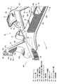
図1は自動車のフロントサブフレーム構造を示す側面図、図2は図1の底面図であり、図1において、エンジンルームと車室とを前後方向に仕切るダッシュロアパネル1(ダッシュパネル)を設け、このダッシュロアパネル1の下部後端には、フロアパネル2を一体または一体的に接合固定している。
上述のフロアパネル2は、車室の底面を形成するパネル部材で、ダッシュロアパネル1の下部後端から後方に向けて略水平に延びると共に、フロアパネル2の車幅方向中央には車室内ヘ突出して車両の前後方向に延びるトンネル部3(フロアトンネル)が一体または一体的に形成されている。
An embodiment of the present invention will be described in detail with reference to the drawings.
1 is a side view showing a front sub-frame structure of an automobile, and FIG. 2 is a bottom view of FIG. 1. In FIG. 1, a dash lower panel 1 (dash panel) for partitioning an engine room and a vehicle compartment in the front-rear direction is provided. The
The
図2に底面図で示すように、トンネル部3の下縁部に沿って車両の前後方向に延びる左右一対のトンネルメンバ4,4を設け、断面ハット形状のトンネルメンバ4を上述のフロアパネル2下面に接合固定して、該フロアパネル2とトンネルメンバ4との間には、前後方向に延びる閉断面を形成している。
上述のフロアパネル2の左右両サイドにはサイドシル5,5を接合固定している。
As shown in a bottom view in FIG. 2, a pair of left and
このサイドシル5は、サイドシルインナとサイドシルアウタとの上下の接合フランジ部を結合して、車両の前後方向に延びるサイドシル閉断面を備えた車体強度部材である。
このサイドシル5と、上述のトンネルメンバ4との車幅方向の中間部には、フロアフレーム6を設けている。
このフロアフレーム6は断面ハット形状に形成され車両の前後方向に延びるフレームであって、該フロアフレーム6をフロアパネル2の下面に接合固定して、フロアパネル2とフロアフレーム6との間には、車両の前後方向に延びる閉断面が形成されている。
The
A
The
図1,図2に示すように、ダッシュロアパネル1の前面部からエンジンルームの左右両サイドを通って前方へ延びる閉断面構造の左右一対のフロントサイドフレーム7,7を設けている。
このフロントサイドフレーム7の後部には、ダッシュロアパネル1の前面部および下面部に沿うキックアップ部7aが一体形成されると共に、該フロントサイドフレーム7と上述のフロアフレーム6とが車両の前後方向に連続するように形成されている。
As shown in FIGS. 1 and 2, a pair of left and right front side frames 7, 7 having a closed cross-sectional structure extending forward from the front portion of the dash
A kick-up
図1に示すように、左右一対のフロントサイドフレーム7,7の前端には、フランジ8,9を介してクラッシュカン10が接続されており、図1,図2に示すように、左右一対のクラッシュカン10,10の前端部相互間には、車幅方向に延びるバンパレイン11が取付けられている。
なお、図2において、12はサスタワー、13はエプロンレイン、14は左右一対のトンネルメンバ4,4を車幅方向に連結する板状のトンネルクロスメンバである。
As shown in FIG. 1, a crash can 10 is connected to the front ends of a pair of left and right front side frames 7 and 7 via
In FIG. 2, 12 is a suspension tower, 13 is an apron rain, and 14 is a plate-shaped tunnel cross member that connects a pair of left and
図3はサブフレーム(サスペンションクロスメンバと同意)の平面図、図4はサブフレームの底面図、図5はサブフレームの斜視図、図6はサブフレームを斜め下方から見上げた状態で示す斜視図である。
図1,図2に示すように、車体の前部に設けられた左右一対のフロントサイドフレーム7,7の下側には、図3〜図6で示すサブフレーム20を架設している。
3 is a plan view of the sub-frame (agreeing with the suspension cross member), FIG. 4 is a bottom view of the sub-frame, FIG. 5 is a perspective view of the sub-frame, and FIG. 6 is a perspective view showing the sub-frame viewed from obliquely below. It is.
As shown in FIGS. 1 and 2, a
図3〜図6に示すように、上述のサブフレーム20は、車両前後方向に延びる管状つまりパイプ製の前後かつ左右一対のサイドメンバ21F,21Rと、
前後のサイドメンバ21F,21R間(サイドメンバの中間部)から上方に延設されて図1,図2で示した左右のフロントサイドフレーム7,7にそれぞれ連結される左右の車体取付け部22(いわゆる「ツノ部材」であり、以下単にタワー部と略記する)と、
前側のサイドメンバ21F,21F間に車幅方向に向けて架設されたフロントクロスメンバ23(いわゆるNo.0クロスメンバ)と、
後側のサイドメンバ21Rの前部間に車幅方向に向けて架設されたセンタクロスメンバ24と、
該センタクロスメンバ24の後部車幅方向中間部と後側のサイドメンバ21Rの後端部との間に、平面視で略V字状に架設された傾斜メンバ25(いわゆるV字ブレース)と、
後側のサイドメンバ21Rの後端と対応する傾斜メンバ25の左右の後部間に車幅方向に延びるように架設されたリヤクロスメンバ26と、
を備えている。
As shown in FIGS. 3 to 6, the above-described
Left and right vehicle body attachment portions 22 (upwardly extending from the front and
A front cross member 23 (so-called No. 0 cross member) erected between the
A
An inclined member 25 (so-called V-shaped brace) laid in a substantially V shape in a plan view between the center portion in the rear vehicle width direction of the
A
It has.
図5,図6に示すように、前側のサイドメンバ21Fの前部にNo.1マウントパイプとしてのフロントマウントパイプM1(ここに、マウントパイプとはマウントブッシュと同意)を連結し、またタワー部22の上部車外側にはNo.2マウントパイプとしてのセンタマウントパイプM2を連結し、さらに傾斜メンバ25の後端部にはNo.4マウントパイプとしてのリヤマウントパイプM4を連結すると共に、リヤクロスメンバ26の左右両側部にはマウントポイントM3を設定している。
As shown in FIG. 5 and FIG. A front mount pipe M1 (here, the mount pipe is the same as a mount bush) is connected as a 1 mount pipe, and a No. A center mount pipe M2 as a two mount pipe is connected, and a No. A rear mount pipe M4 as a four mount pipe is connected, and mount points M3 are set on the left and right sides of the
そして、図1,図2に示すように、左右一対のフロントマウントパイプM1,M1をフロントサイドフレーム7の前部下面に連結し、左右一対のセンタマウントパイプM2,M2をフロントサイドフレーム7の前後方向中間部下面に連結し、左右一対のリヤマウントパイプM4,M4をフロントサイドフレーム7の後部下面に連結し、左右一対のマウントポイントM3,M3を、図示しないNo.3マウントパイプを用いて、トンネルメンバ4の前部下面に連結している。
つまり、サブフレーム20は片側4点、左右両側で計8点にて車体にマウントされたものである。
1 and 2, a pair of left and right front mount pipes M1 and M1 are connected to the front lower surface of the
That is, the
図5,図6に示すように、前側のサイドメンバ21Fは金属角パイプをハイドロフォーム加工して断面方形枠状に形成したもので、該サイドメンバ21Fには車両の前後方向に延びる閉断面が形成されている。
また、後側のサイドメンバ21Rは金属丸パイプで形成されており、該サイドメンバ21Rには車両の前後方向に延びる閉断面が形成されている。
さらに、上述のフロントクロスメンバ23は金属角パイプを加工して形成されており、該フロントクロスメンバ23には車幅方向に延びる閉断面が形成されている。
As shown in FIGS. 5 and 6, the
The
Furthermore, the above-mentioned
上述のフロントクロスメンバ23の車幅方向中央部下部には樹脂製のジャッキリテーナ27が取付けられており、車両ジャッキアップ時に該ジャッキリテーナ27をジャッキアップポイントとして利用できるように構成している。
上述の前側のサイドメンバ21Fの前端部には、図1,図2に示すようにフランジ28,29を介してサブクラッシュカン30が取付けられている。このサイドメンバ21F前端のサブクラッシュカン30、および、前述のフロントサイドフレーム7前端のクラッシュカン10は何れも衝撃吸収部材である。
上述のセンタクロスメンバ24は、左右のサイドメンバ21Rを連結すると共に、断面略ハット形状のセンタクロスメンバアッパ24aと、下側に位置するセンタクロスメンバロア24bとを接合固定して、車幅方向に延びる閉断面24c(図8参照)を形成したものである。そして、該センタクロスメンバ24の車幅方向中央前面には、後述するパワートレインマウント50用の開口部24dを形成すると共に、この開口部24dと対応して上述のセンタクロスメンバアッパ24a、センタクロスメンバロア24bには、センタクロスメンバ24の車幅方向中央部において左右側部の後縁より車両後方に膨出する膨出部24e,24eを一体形成し、これら上下の膨出部24e,24e間に、傾斜メンバ25の前部中央を連結している(図1参照)。
そして、センタクロスメンバ24と傾斜メンバ25とサイドメンバ21Rとの間には、左右一対の開口Sが形成されている。
A resin-made
As shown in FIGS. 1 and 2, a sub-crash can 30 is attached to the front end portion of the above-mentioned front side member 21 </ b> F via
The above-described
A pair of left and right openings S are formed between the
図3,図4に示すように、上述の膨出部24eは車両後方に向けて略台形状に突出するもので、膨出部24eの左右外殻には前後方向に延びる左右一対の傾斜状の縦壁部24e1,24e1が形成されている。そして、この膨出部24eの後側傾斜壁と傾斜メンバ25との間を、角パイプ製で閉断面構造の左右一対のブレース31,31にて、前後方向に連結している。
そして、この実施例では、センタクロスメンバ24の前縁よりも後方で、かつ傾斜メンバ25よりも前方に、パワートレインマウント50用のマウント取付け部51が配設されており、このマウント取付け部51が膨出部24e,24eにより構成されている。
上述の傾斜メンバ25は、フロントクロスメンバ23よりも後方(車室側)で車幅方向に延設されることにより、車室側クロスメンバを構成しており、リヤマウントパイプM4,M4を介して車体に支持されている。
また、傾斜メンバ25は、金属角パイプを加工して形成された閉断面構造部材であって、該傾斜メンバ25は、図3〜図6に示すように、前側に位置して車幅方向に延びる中央部25aと、この中央部25aに向かって車幅方向内方かつ前方(車室と反対側の前後方向外側)に延びる傾斜部25bと、傾斜部25bの後端から車幅方向外方に延びる後部25cとを一体形成したものである。
As shown in FIGS. 3 and 4, the bulging
In this embodiment, the
The
The
図3,図4に示すように、後側のサイドメンバ21Rは、傾斜メンバ25から前方に延びると共に、その後端が、傾斜メンバ25における傾斜部25bの後方側前面(前後方向外側の面)に突き当てられて連結されている。
そして、傾斜メンバ25がサイドメンバ21Rに連結される接続部から車幅方向外側に離間した位置には上述したリヤマウントパイプM4が配設され、上記接続部と反対側の位置には、上述したマウントポイントM3が設定されている。
また、該サイドメンバ21Rと傾斜メンバ25の後部25cとの間には、ロアアーム40(図5参照)の後側を上側、下側からそれぞれ支持する上下のロアアームブラケット32,33が取付けられており、いずれもリヤマウントパイプM4よりも前方に離間した位置に配設されている。これら上下のロアアームブラケット32,33にはビード等の凹凸部が一体形成されていて、該ロアアームブラケット32,33それ自体の剛性が高められている。
As shown in FIGS. 3 and 4, the rear side member 21 </ b> R extends forward from the
The above-described rear mount pipe M4 is disposed at a position separated from the connecting portion connected to the
Further, between the
また、上側のロアアームブラケット32は、一端がサイドメンバ21Rに連結され、他端が、車幅方向外側のリヤマウントパイプM4から車幅方向内側に離間して、マウントポイントM3とリヤマウントパイプM4との間で傾斜メンバ25の後部25cの屈曲部25c´(図3,図11参照)前面に連結される一方、下側のロアアームブラケット33は、一端がサイドメンバ21Rに連結され、他端が傾斜メンバ25の後部25c(リヤマウントパイプM4)の下部と連結されている。
The upper
また、図3,図4に示すように、上述のリヤクロスメンバ26は板金製で断面門形のリヤクロスメンバアッパ26aと、該リヤクロスメンバアッパ26aの下部において左右の車幅方向外側部に接合固定されたリヤクロスメンバロア26b,26bとを備えており、上側に位置するリヤクロスメンバアッパ26aが傾斜メンバ25の左右の後部25c,25c間に、平面から見て該後部25cと略一直線状になるように車幅方向に向けて架設されたものである。
リヤクロスメンバ26には、その車幅方向両端部にて上述したマウントポイントM3,M3が設定されている。
As shown in FIGS. 3 and 4, the above-mentioned
The mount points M3 and M3 described above are set on the
図7は図3のA−A線に沿う車両右側の矢視断面図、図8は図3のB−B線に沿う車両右側の矢視断面図であって、上述の車体取付け部としてのタワー部22は、図7,図8に示すようにコ字状断面のマウントブラケットアッパ22aと、該マウントブラケットアッパ22aに接合固定されるマウントブラケットロア22bとを備えており、リヤマウントパイプM4やセンタクロスメンバ24の中央部よりも前方に離間した位置に配設されている。
7 is a cross-sectional view of the right side of the vehicle along the line AA in FIG. 3, and FIG. 8 is a cross-sectional view of the right side of the vehicle along the line BB in FIG. As shown in FIGS. 7 and 8, the
図8に示すように、上述のタワー部22は、少なくともその下部を含んでサイドメンバ21F,21R下面から車幅方向外側および上方に延設される閉断面22cを有している。
この実施例では、上述の閉断面22cは斜め上方かつ車外側に延びており、斜め上方かつ車外側に延びる閉断面22cの下部部位には、ロアアーム40(図5参照)の前側を支持する前後のロアアーム支持部22d,22e(図4参照)が設けられると共に、その下端の下面部22fが図7に示すようにセンタクロスメンバ24のセンタクロスメンバロア24bに連結されており、この構成により、ロアアーム40からの入力荷重(特に、車両旋回時等における横荷重)をフロントサイドフレーム7に分散すると共に、該入力荷重をセンタクロスメンバ24に円滑に伝達して、荷重分散を図るように構成している。ここで、上述の前後のロアアーム支持部22d,22eはマウントブラケットロア22bに対して下方に突出すべく隆起形成されていて、この隆起構造により、ロアアーム支持部22d,22eそれ自体の強度が高められている。
As shown in FIG. 8, the above-described
In this embodiment, the above-described closed
図5に示すように、上述のタワー部22は、その下部が略ボックス形状に形成されると共に、該ボックス形状部から上方に延びる部分がツノ形状に形成されている。また、サイドメンバは前側のサイドメンバ21Fと、後側のサイドメンバ21Rとに前後2分割されており、図3,図4に示すように、前側のサイドメンバ21Fの後端がタワー部22の略ボックス形状部に前面に連結され、後側のサイドメンバ21Rの前端がタワー部22の略ボックス形状部の後面に連結されていて、荷重入力時にサイドメンバ21F,21Rの閉断面を潰すことなく、センタクロスメンバ24に荷重を伝達して、荷重分散を図るように構成している。
換言すれば、前後の各サイドメンバ21F,21Rはタワー部22の閉断面構造の略ボックス形状部を介して、車両の前後方向に連続するように構成されたものである。
As shown in FIG. 5, the lower portion of the above-described
In other words, the front and rear side members 21 </ b> F and 21 </ b> R are configured to be continuous in the front-rear direction of the vehicle via the substantially box-shaped portion of the closed section structure of the
図7,図8に示すように、上述のタワー部22のロアアーム支持部22d,22eは車幅方向外側面部に形成されており、ロアアーム40の支持ブラケット41を、ボルト42、ナット43などの締結部材を用いてロアアーム支持部22d,22eに支持させる際の組付け性を確保すると共に、タワー部22の閉断面22cを、フロントサイドフレーム7からサイドメンバ21F,21Rの間で滑らかに形成するように構成している。
As shown in FIGS. 7 and 8, the lower
また、図8に示すように、タワー部22における車幅方向外側面部、つまり、マウントブラケットアッパ22aとマウントブラケットロア22bのうち車幅方向の外側面に位置するマウントブラケットロア22bは、サイドメンバ21F,21Rとフロントサイドフレーム7との間に略直線的に傾斜するように構成されていて、横荷重の分散性能向上を図るように構成している。
さらに、図6,図7,図8に示すように、タワー部22のロアアーム支持部22d,22eは、その閉断面22cが略前後に分岐して、前側支持部22dと後側支持部22eとが形成されており、上述の閉断面22cそれ自体でロアアーム支持部22d,22eの剛性を高め、これにより、ロアアーム40の支持剛性向上を図るように構成している。
Further, as shown in FIG. 8, the mount bracket lower 22b located on the outer side surface in the vehicle width direction of the
Further, as shown in FIGS. 6, 7, and 8, the lower
図3,図8に示すように、センタクロスメンバ24とタワー部22とが車両前後方向で重なる位置において、タワー部22の下部の上面部22gには、部分的に水平部22hを形成し、この水平部22hにはボルト34、ナット35などの締結部材を用いて、補機取付けブラケットとしてのスタビライザ支持ブラケット36,37の前部を取付けるように構成している。
3 and 8, at the position where the
図5に斜視図で示すように、下側のスタビライザ支持ブラケット36は平板状に形成されており、上側のスタビライザ支持ブラケット37は略Ω字状に形成されており、これらの上下のスタビライザ支持ブラケット36,37で補機としてのズタビライザ(図示せず)を支持するものである。
スタビライザは、周知のように、ねじり剛性の抵抗により片輪のみのバンプ、リバウンド時にロール角を抑制するものである。
As shown in a perspective view in FIG. 5, the lower
As is well known, the stabilizer suppresses the roll angle at the time of rebound and bump of only one wheel by resistance of torsional rigidity.
図3,図4に示すように、上述のサイドメンバ21Rには前後方向に間隔を隔ててスタビライザ取付け用のブッシュ45と、ステアリングラック取付け用のブッシュ46とを設けている。これらの各ブッシュ45,46はサイドメンバ21Rの上下面を溶接にて連結する剛性パイプにより形成されている。
ここで、上述のスタビライザ取付け用のブッシュ45には、図8と同様にボルト、ナット等の締結部材を用いて、スタビライザ支持ブラケット36,37の後部が取付けられている(図5参照)。
As shown in FIGS. 3 and 4, the side member 21 </ b> R is provided with a
Here, the
図8に示すように、上述の水平部22hを含むタワー部22の下部の上面部22gは、センタクロスメンバ24に連結されており、サイドメンバ21F,21Rの閉断面の潰れをより一層良好に防止すると共に、タワー部22のセンタクロスメンバ24に対する結合強度の向上を図るように構成している。
As shown in FIG. 8, the
図4に示すように、上述のセンタクロスメンバ24は、その車幅方向全長において上述のタワー部22の前側支持部22dまたは後側支持部22eの少なくとも一方、この実施例では、後側支持部22eと車両前後位置が重なるようにタワー部22から後方にずれて配設されており、車幅方向荷重伝達経路の確保と、自動車用のエンジンまたは駆動モータからなる前部機関タイプのパワートレインPT(図3,図4参照)のレイアウト性確保との両立を図るように構成している。
As shown in FIG. 4, the
図3,図5に示すように、センタクロスメンバ24には、その左右両端部を車両前後方向でタワー部22のマウント部側、詳しくは、前側のロアアーム支持部22d側に傾斜して延ばすことにより、斜め外側前方に延設された延長部24fが形成されると共に、図4に示すように、タワー部20のマウントブラケットロア22bには、その車幅方向内側部が車両前後方向でセンタクロスメンバ24の両サイド部前側まで傾斜して延びる延長部22jが一体形成されており、この延長部22jがセンタクロスメンバ24と連結され、車両前後方向反対側(つまり後側)の車幅方向中間部には、前述の傾斜メンバ25が連結されている。
そして、傾斜メンバ25では、傾斜部25bが、平面視で後側のリヤマウントパイプM4から車幅方向の反対側のロアアーム支持部22d,22eに向かって延設されている。
この構成により、車幅方向および傾斜方向の荷重伝達経路を確保するように構成している。
As shown in FIGS. 3 and 5, the
In the
With this configuration, load transmission paths in the vehicle width direction and the inclination direction are secured.
すなわち、図3,図4に実線矢印α1で示すように、右側のロアアーム支持部22dから荷重が入力されると、該荷重を延長部22jからセンタクロスメンバ24に伝達した後に、その一部を、図3,図4の実線矢印α2で示すように、センタクロスメンバ24の前縁に沿って車幅方向に伝達させると同時に、実線矢印α3で示すように、該センタクロスメンバ24から傾斜メンバ25の左側の傾斜部25bにも分岐して伝達させることができる。
逆に、左側のロアアーム支持部22dから荷重が入力されると、図3,図4に点線矢印β1で示すように、該荷重を延長部22jからセンタクロスメンバ24に伝達した後に、その一部を、図3,図4の点線矢印β2で示すように、センタクロスメンバ24の前縁に沿って車幅方向に伝達させと同時に、点線矢印β3で示すように、該センタクロスメンバ24から傾斜メンバ25の右側の傾斜部25bにも分岐して伝達させることができる。
これにより、左右のロアアーム支持部22d,22eからの荷重伝達経路が、センタクロスメンバ24に沿って伝達する車幅方向荷重伝達経路(矢印α2,β2)と、センタクロスメンバ24を介して傾斜メンバ25を平面視で略X字状に伝達する傾斜方向荷重伝達経路(矢印α3,β3)とを確保することができる。
That is, as indicated by the solid arrow α1 in FIGS. 3 and 4, when a load is input from the right lower
Conversely, when a load is input from the left lower
As a result, the load transmission path from the left and right lower
特に、この実施例では、タワー部22のセンタマウントパイプM2(いわゆるNo.2マウントパイプ)と、後側のロアアーム支持部22eとセンタクロスメンバ24の前部とを車幅方向に略一直線状に配置することで、上述した車幅方向荷重伝達経路を形成している。これにより、センタクロスメンバ24の前縁の後方でマウント取付け部51の設置スペースを確保して、パワートレインPTのレイアウト性を確保しつつ、ロアアーム支持部22d,22eからの荷重入力時に車幅方向の荷重伝達が円滑に行なわれるように構成している。
In particular, in this embodiment, the center mount pipe M2 (so-called No. 2 mount pipe) of the
具体的には、荷重入力時に上述した車幅方向荷重伝達経路と傾斜方向荷重伝達経路とが形成されることにより、センタクロスメンバ24の前縁より後方の車幅方向中央部には、上記荷重伝達経路が形成されない低応力部が形成される。
この実施例では、上記荷重伝達経路を避けるようにして、上記低応力部にマウント取付け部51を配設している。これにより、上記荷重の影響が、パワートレインPTの後面中央部に設けられたパワートレインマウント50に及ぶことを防止しつつ、これをセンタクロスメンバ24にコンパクトに配設することが可能になっており、これによって、パワートレインPTのレイアウト性を確保している。
Specifically, when the vehicle width direction load transmission path and the inclination direction load transmission path described above are formed when a load is input, the load in the vehicle width direction center behind the front edge of the center cross member 24 A low-stress part in which a transmission path is not formed is formed.
In this embodiment, the
図9はマウント取付け部を示す要部拡大断面図、図10は図9のC−C線に沿う矢視断面図であって、上述のセンタクロスメンバ24の膨出部24eでは、図5,図9,図10に示すように、マウント取付け部51の左右に前後方向に延びる縦壁からなる内部隔壁52,52が配設され、この内部隔壁52,52の前後端がそれぞれセンタクロスメンバ24の前後面に接続されている。そして、左右の内部隔壁52,52に対応する後方位置には、上述したブレース31,31が配設され、このブレース31により、膨出部24e(マウント取付け部51)の後部を補強すべく構成している。
FIG. 9 is an enlarged cross-sectional view of the main part showing the mount mounting portion, and FIG. 10 is a cross-sectional view taken along the line CC of FIG. 9, and in the bulging
また、マウント取付け部51では、上述した開口部24dが、センタクロスメンバ24の前縁の左右側端と、傾斜メンバ25との連結部位とを結ぶ仮想線L,L(図2の一点鎖線参照)に交わらない位置に配設され、上記前縁から後方かつ下方に離間している。
さらに、センタクロスメンバ24の前面には、車幅方向に延びて上記前縁をバイパスするバイパス経路24gが、開口部24dを挟んで上記前縁の反対側に配設されている。
Further, in the
Further, on the front surface of the
この構成により、車幅方向荷重は、図3に実線矢印α21、点線矢印β21で示すように、開口部24dの前方の前縁に沿って車幅方向に伝達されると同時に、一部が、図3に実線矢印α22、破線矢印β22で示すように、上記前縁から分岐してバイパス経路24gにも伝達される。
一方、傾斜方向荷重は、図3に実線矢印α31、点線矢印β31で示すように、膨出部24eの縦壁部24e1,24e1を介して傾斜メンバ25に伝達されると同時に、一部が、図10に実線矢印α32、破線矢印β32で示すように、内部隔壁52,52を介して傾斜メンバ25に伝達される。
With this configuration, the load in the vehicle width direction is transmitted in the vehicle width direction along the front edge in front of the
On the other hand, as shown by solid line arrows α31 and dotted line arrows β31 in FIG. 3, the load in the inclined direction is transmitted to the
ところで、パワートレインマウント50は、図1,図5,図9,図10に示すように、円筒状をなしており、その中心部の内筒がボルト53、ナット54等の締結部材で上下の膨出部24e,24eに連結固定されることにより、マウント取付け部51の空間内(ここでは、上下の膨出部24e,24e間の空間内)に取付けられている。センタクロスメンバ24では、パワートレインマウント50を取付けるボルト53、ナット54によって上下の膨出部24e,24eが連結されることにより、膨出部24eを含むセンタクロスメンバ24全体が補強された構成になっている。
また、パワートレインPTの後部には、リンク55が取付けられており、このリンク55が開口部24dに挿通され、マウント取付け部51内部のパワートレインマウント50に連結されることで、パワートレインPTの後部がサブフレーム20に支持されている。
By the way, the
In addition, a
また、図3,図4に示すように、センタクロスメンバ24の車幅方向両端部における後端部は、スタビライザ取付け用のブッシュ45と前後方向でオーバラップさせており、スタビライザを車幅方向に通しながらサイドメンバ21Rの閉断面潰れを防止するように構成している。
As shown in FIGS. 3 and 4, the rear ends of the
図7,図8に示すように、センタマウントパイプM2とタワー部22の接続構造は、次のようになっている。
すなわち、タワー部22はマウントブラケットアッパ22aに一体形成された上壁22kおよび前後の縦壁22m,22mと、マウントブラケットロア22bに一体形成された下壁22nとを独立的に備えており、例えば、特開2011−162159号公報と同様、上壁22kおよび縦壁22m,22mをセンタマウントパイプM2に溶接する一方で、下壁22nはセンタマウントパイプM2を非溶接となし、さらに前後の縦壁22m,22mの基部上下に切欠き部22p,22qを設け、車両の前突時にセンタマウントパイプM2を車体に残してサブフレーム20の車体取付け部(タワー部22)が離脱可能となるように構成して、パワートレインPTの後退を許容可能に構成している。
As shown in FIGS. 7 and 8, the connection structure between the center mount pipe M2 and the
That is, the
図11,図12は衝突(前突)荷重入力時の説明図であって、車両衝突(前突)時に衝突荷重が車両前方から入力されると、フロントサイドフレーム7,7が変位を開始すると同時に、衝撃吸収部材としてのサブクラッシュカン30が、図12に示すように前後方向に潰れて衝撃(衝突荷重)を吸収する。
そして、サブフレーム20では、下側のロアアームブラケット33の他端が傾斜メンバ25の後部25c(リヤマウントパイプM4)の下部と連結されていることにより、上記衝突荷重が、フロントサイドフレーム7、サイドメンバ21F,21R、およびロアアームブラケット33を介して、図11に実線矢印γに示すように、後部25c(リヤマウントパイプM4)の下部に入力される。
この時、上側のロアアームブラケット32の他端(屈曲部25c´)では、これがリヤマウントパイプM4から離間していることにより、入力される衝突荷重は、リヤマウントパイプM4の下部よりも小さくなる。
この実施例では、上記衝突荷重がリヤマウントパイプM4の下部に偏って入力されることにより、リヤマウントパイプM4の下部に応力が集中して、図11に実線矢印δに示すように、リヤマウントパイプM4の下部を後方に変位させる捩りモーメントが発生し、この捩りモーメントの作用によって、図11に二点鎖線で示すように、後部25cを捩るようになっている。そして、この後部25cの捩れにより、フロントサイドフレーム7からリヤマウントパイプM4を離脱させることが可能になっている。
FIGS. 11 and 12 are explanatory diagrams when a collision (front collision) load is input. When a collision load is input from the front of the vehicle at the time of a vehicle collision (front collision), the front side frames 7 and 7 start to be displaced. At the same time, the sub-crash can 30 as an impact absorbing member is crushed in the front-rear direction as shown in FIG. 12 to absorb the impact (collision load).
In the
At this time, at the other end (
In this embodiment, the collision load is input to the lower portion of the rear mount pipe M4 so that stress concentrates on the lower portion of the rear mount pipe M4, and as shown by the solid arrow δ in FIG. A torsional moment that causes the lower portion of the pipe M4 to be displaced rearward is generated, and the action of this torsional moment causes the
さらに、サイドメンバ21Rの後端が傾斜メンバ25の後方側前面に突き当てられて接続されていることにより、図11に二点鎖線で示すように、傾斜メンバ25の後方側前面がサイドメンバ21Rによって前後方向に潰れ、この傾斜メンバ25の潰れに伴って、サイドメンバ21R,21Fが、図11,図12に実線矢印εに示すように、フロントサイドフレーム7に対して後方に相対変位する。
そして、さらに衝突荷重が入力されると、傾斜メンバ25の傾斜部25b全体が、図11に実線矢印ζに示すように、リヤマウントパイプM4を中心にして後方かつ車幅方向内方に向かって回動するように変形する。この時、サイドメンバ21Rとの接続部が後方に変位することになるため、サイドメンバ21R,21Fの相対変位がより促進される。
Further, since the rear end of the
When a collision load is further input, the entire
このように、サイドメンバ21Rが相対移動すると、タワー部22にて切欠き部22p,22qが設けられていることにより、特開2011−162159号公報と同様に、センタマウントパイプM2では三次元的なねじれが発生する。
そして、下壁22nとセンタマウントパイプM2とを非溶接となすことによって、センタマウントパイプM2の下部が、側部、前部および後部よりも低剛性に設定されているので、タワー部22の一部に応力が集中して、センタマウントパイプM2とタワー部22との接合が外れる。
As described above, when the
Since the
このように、タワー部22において、その下壁22nがセンタマウントパイプM2と非溶接となし、かつ縦壁22m,22mの基部上下に切欠き部22p,22qを設けていることで、サイドメンバ21F,21Rがフロントサイドフレーム7に対して相対変位した時には、センタマウントパイプM2とタワー部22との接合を外して、フロントサイドフレーム7から車体取付け部(タワー部22)を離脱させることが可能になっている。つまり、タワー部22の下壁22nおよび切欠き部22p,22qは、サイドメンバ21F,21Rがフロントサイドフレーム7に対して相対変位することで、該フロントサイドフレーム7から車体取付け部(タワー部22)を離脱可能な離脱手段として機能している。
As described above, in the
なお、サイドメンバ21F,21Rの相対変位によって車体取付け部(タワー部22)を離脱させる構成は、必ずしもこれに限定されるものではない。例えば、タワー部22を鋳造製とし、その一部に切欠き部を形成したものであってもよい。この場合、切欠き部が離脱手段として機能し、切欠き部を起点としたタワー部22の変形によってこれをフロントサイドフレーム7から離脱させることができる。
また、センタマウントパイプM2や、センタマウントパイプM2とタワー部22とを締結する締結部材の一部に脆弱部(切欠き、薄肉部等)を設け、この脆弱部と起点した変形、破損によってタワー部22を離脱させるようにしてもよい。この場合、センタマウントパイプM2や締結部材に設けられた脆弱部が離脱手段として機能することになる。
また、離脱手段の作動によって車体取付け部(タワー部22)を離脱させる部位は、センタマウントパイプM2と対応する中間部(タワー部22)であることに必ずしも限定されず、フロントマウントパイプM1と対応する前部であってもよい。
In addition, the structure which makes a vehicle body attachment part (tower part 22) detach | leave by the relative displacement of the
Further, a weak portion (notch, thin portion, etc.) is provided in a part of a fastening member that fastens the center mount pipe M2 or the center mount pipe M2 and the
Further, the part from which the vehicle body attachment part (tower part 22) is detached by the operation of the detaching means is not necessarily limited to the intermediate part (tower part 22) corresponding to the center mount pipe M2, and corresponds to the front mount pipe M1. It may be the front part.
図2,図4,図6において、22xはロアアーム40との干渉を回避するためにマウントブラケットロア22bに形成された凹部である。また、図中、矢印Fは車両の前方を示し、矢印INは車幅方向の内方を示し、矢印OUTは車幅方向の外方を示す。
2, 4, and 6, 22 x is a recess formed in the mount bracket lower 22 b in order to avoid interference with the
このように、図1〜図12で示した自動車のフロントサブフレーム構造は、左右一対のサイドメンバ21F,21F,21R,21Rと、該左右一対のサイドメンバ21F,21F,21R,21Rを連結して車幅方向に延びる閉断面構造のセンタクロスメンバ24と、該センタクロスメンバ24の中央部後面に連結された平面視略V字状の傾斜メンバ25とが配設されると共に、センタクロスメンバ24の前縁よりも後方で、かつ傾斜メンバ25よりも前方に、パワートレイン用マウント50のマウント取付け部51が配設されたものである(図1〜図6,図9〜図11参照)。
Thus, the front subframe structure of the automobile shown in FIGS. 1 to 12 connects the pair of left and
この構成によれば、平面視略V字状の傾斜メンバ25によってセンタクロスメンバ24を補強することができるため、サブフレーム20の高剛性化を図ることができる。
そして、センタクロスメンバ24に沿って荷重を伝達する車幅方向荷重伝達経路と、センタクロスメンバ24を介して傾斜メンバ25に平面視で略X字状に荷重を伝達する傾斜方向荷重伝達経路とを避けるようにして、パワートレイン用マウント50をセンタクロスメンバ24に配設することができる。これにより、上記荷重の影響がパワートレイン用マウント50に及ぶことを防止しつつ、これをコンパクトに配設することができる。
According to this configuration, since the
A vehicle width direction load transmission path for transmitting a load along the
要するに、サブフレーム20の高剛性化を図りつつ、パワートレイン用マウント50をコンパクトに配設することができるものである。
また、センタクロスメンバ24の前部が、左右のサスペンションのアーム(ロアアーム40)を支持するロアアーム支持部22d,22eを直線的に結ぶ車幅方向荷重伝達経路を形成し、該経路の後方に、マウント取付け部51が配設されたものである(図3,図4参照)。
In short, the
Further, the front portion of the
この構成によれば、ロアアーム支持部22d,22eとセンタクロスメンバ24の少なくとも一部とが前後同一位置に配設されることになる。この場合、ロアアーム支持部22d,22eから入力した荷重を、上記車幅方向荷重伝達経路によって車幅方向に伝達することができ、通常時における車幅方向剛性を高めることができる。
また、マウント取付け部51は、センタクロスメンバ24の中央部を左右側部の後縁よりも後方に膨出させた膨出部24eにより構成されると共に、該膨出部24eは、傾斜メンバ25と連結されたものである(図1〜図6,図9〜図11参照)。
According to this configuration, the lower
Further, the
この構成によれば、パワートレイン用マウント50を配設したセンタクロスメンバ24を前後方向にコンパクト化しつつ、傾斜メンバ25と連結された膨出部24eを傾斜方向荷重伝達経路として利用することができる。このため、上記傾斜方向荷重を膨出部24eに沿って円滑に伝達することができ、その結果、軽量高剛性化を図ることができる。
また、センタクロスメンバ24の左右端部が、斜め外側前方に延設され、左右のサスペンションのアーム(ロアアーム40)を支持するロアアーム支持部22d,22eが、センタクロスメンバ24の中央部よりも前方に延設されたものである(図1〜図6,図9〜図11参照)。
According to this configuration, the
The left and right end portions of the
この構成によれば、ロアアーム支持部22d,22eをセンタクロスメンバ24の中央部より前方に配設しても、センタクロスメンバ24の前縁に沿った車幅方向荷重伝達経路と、センタクロスメンバ24における傾斜方向荷重伝達経路とを、斜め外側前方に延設された左右端部によって確保することができる。このため、センタクロスメンバ24の中央部をロアアーム支持部22d,22eよりも相対的に後方に配設することが可能になり、センタクロスメンバ24を後方に配設することで、パワートレインPTの配設スペース拡大を図ることができる。
要するに、センタクロスメンバ24における荷重伝達剛性を高めつつ、パワートレインPTの配設スペース拡大を図ることができるものである。
また、傾斜メンバ25の左右の後部が、車体と連結されたものである(図1〜図6,図9〜図12参照)。
According to this configuration, even if the lower
In short, it is possible to increase the space for arranging the power train PT while increasing the load transmission rigidity in the
The left and right rear portions of the
この構成によれば、傾斜方向荷重を、サイドメンバ21F,21Rを介することなく車体側に直接伝達することができるため、上記傾斜方向荷重の車体への伝達剛性を高めることができる。
また、マウント取付け部51の左右に、前後方向に延びる縦壁からなる内部隔壁52,52が設けられたものである(図10参照)。
According to this configuration, since the load in the tilt direction can be directly transmitted to the vehicle body without passing through the
In addition,
この構成によれば、センタクロスメンバ24の傾斜方向荷重を、内部隔壁52,52を介して傾斜メンバ25へ略X字状に円滑に伝達することができる。
また、マウント取付け部51の左右外殻に、前後方向に延びる縦壁部24e1,24e1が形成されたものである(図3,図5参照)。
According to this configuration, the load in the tilt direction of the
Further, vertical wall portions 24e1 and 24e1 extending in the front-rear direction are formed on the left and right outer shells of the mount mounting portion 51 (see FIGS. 3 and 5).
この構成によれば、センタクロスメンバ24の傾斜方向荷重を、縦壁部24e1,24e1を介して傾斜メンバ25へ略X字状に円滑に伝達することができる。
また、センタクロスメンバ24と傾斜メンバ25とサイドメンバ21Rとの間に開口Sが形成されたものである(図2〜図6,図10,図11参照)。
According to this configuration, the load in the tilt direction of the
Further, an opening S is formed among the
この構成によれば、荷重伝達経路以外の部位を開口Sの形成によって省略することができるため、サブフレーム20の軽量化を図ることができる。
また、上記クロスメンバの表面積を縮小することができるため、該クロスメンバにおける騒音、振動を低減することができる。
また、マウント取付け部51には、センタクロスメンバ24の前縁の左右側端と、傾斜メンバ25との連結部位とを結ぶ仮想線L,Lに交わらず、かつ上記前縁から後方に離間した位置にある前面に、パワートレイン用マウント50に連結されるリンク55を挿通する開口部24dが配設され、該開口部24dは、上記前縁から上下方向に離間して配設されたものである(図3参照)。
According to this configuration, parts other than the load transmission path can be omitted by forming the opening S, so that the weight of the
Further, since the surface area of the cross member can be reduced, noise and vibration in the cross member can be reduced.
In addition, the
この構成によれば、開口部24dが、車幅方向荷重の集中するセンタクロスメンバ24の前縁から上下方向(ここでは上方)に離間して配設されているので、センタクロスメンバ24の前面においてその一部を開口部24dで寸断することなく、車幅方向荷重を伝達することができる。従って、センタクロスメンバ24の車幅方向荷重に対する荷重伝達剛性向上と前後方向のコンパクト化とを両立する上で好ましい構成となる。
また、センタクロスメンバ24の前面には、車幅方向に延びて上記前縁をバイパスするバイパス経路24gが、開口部24dを挟んで上記前縁の反対側に配設されたものである(図1,図3,図5,図6,図9参照)。
According to this configuration, the
Further, on the front surface of the
この構成によれば、車幅方向荷重の一部をバイパス経路24gにも伝達させることにより、これを開口部24dの上下に分散することができる。この場合、開口部24gとセンタクロスメンバ24の前縁との間の部位にかかる負荷を軽減することができるため、結果として、センタクロスメンバ24の車幅方向荷重に対する荷重伝達剛性を高めることができる。
According to this configuration, a part of the vehicle width direction load is also transmitted to the
図13〜図21は自動車のフロントサブフレーム構造の他の実施例を示し、図13はその側面図、図14は図13の底面図、図15はサブフレーム構造を示す斜視図、図16はその分解斜視図、図17は図15の部分拡大斜視図、図18は図17で示した車体取付け部としてのタワー部の周辺構造を下方から見上げた状態で示す斜視図、図19は図15のD−D線に沿う車両右側の矢視断面図、図20は図15のE−E線に沿う車両右側の矢視断面図、図21は図14のG−G線に沿う車両右側の矢視断面図である。
図13〜図21において、図1〜図12と同一の部分には同一符号を付している。
FIGS. 13 to 21 show another embodiment of the front subframe structure of an automobile, FIG. 13 is a side view thereof, FIG. 14 is a bottom view of FIG. 13, FIG. FIG. 17 is a partially enlarged perspective view of FIG. 15, FIG. 18 is a perspective view showing the peripheral structure of the tower portion as the vehicle body attachment portion shown in FIG. 17 as viewed from below, and FIG. 20 is a cross-sectional view of the right side of the vehicle along the line DD, FIG. 20 is a cross-sectional view of the right side of the vehicle along the line EE of FIG. 15, and FIG. 21 is a right side view of the vehicle along the line GG of FIG. It is arrow sectional drawing.
13 to 21, the same parts as those in FIGS. 1 to 12 are denoted by the same reference numerals.
図13〜図21に示すこの実施例においては、前側のサイドメンバ21Fと後側のサイドメンバ21Rとを前後方向に一体連結している。これらの各サイドメンバ21F,21Rは金属パイプをハイドロフォーム加工することで、前側を断面方形枠状に、後側を丸パイプ形状に一体形成することができる。
In this embodiment shown in FIGS. 13 to 21, a
図21に断面図で示すように、この実施例においても、タワー部22はマウントブラケットアッパ22aとマウントブラケットロア22bとを備えており、該タワー部22はサイドメンバ21F,21Rの下面から車幅方向外側および上方に延びる閉断面22cを有していて、該閉断面22cの下部には、図21,図18に示すように、前後のロアアーム支持部22d,22eが設けられると共に、その下端の下面部22fがサイドメンバ21Rの下面に溶接にて連結されている。
また、図17に斜視図で示すように、左右のタワー部22(但し、図面では右側のタワー部22のみを示す)の下部の上面部22gがサイドメンバ21F,21Rの上面に溶接にて連結されている。
As shown in a cross-sectional view in FIG. 21, in this embodiment as well, the
Further, as shown in a perspective view in FIG. 17,
図18,図21に示すように、タワー部22の前後のロアアーム支持部22d,22eは車幅方向外側面部に形成されており、該車幅方向外側面部つまりマウントブラケットロア22bは、図21に示すように、サイドメンバ21F,21Rとフロントサイドフレーム7との間に略直線的に傾斜するように形成されている。
As shown in FIGS. 18 and 21, the front and rear lower
図18に示すように、この実施例においても、タワー部22の前後のロアアーム支持部22d,22eは、その閉断面22cが略前後に分岐して、前側支持部22dと後側支持部22eとが形成されている。
As shown in FIG. 18, also in this embodiment, the lower
図14に底面図で示すように、センタクロスメンバ24は、その車幅方向の全長においてタワー部22の後側支持部22eと車両前後位置が重なるように上述のタワー部22から後方にずれて配置されている。
しかも、同図に示すように、センタクロスメンバ24には、その左右両端部を車両前後方向でタワー部22のマウント部側、詳しくは、前側のロアアーム支持部22d側に傾斜して延ばすことにより、斜め外側前方に延設された延長部24fが形成されており、この延長部24fが、図14,図17,図18に示すように、サイドメンバ21F,21Rと連結されており、サンタクロスメンバ24において該延長部24fが形成された側に対して車両前後方向の反対側つまり後側の車幅方向中央部には左右側部の後縁より後方に突出する膨出部24eが一体形成されていて、この膨出部24eには、図14,図15に示すように傾斜メンバ25が連結されている。
As shown in the bottom view of FIG. 14, the
Moreover, as shown in the figure, the
上述のセンタクロスメンバ24はセンタクロスメンバアッパ24aとセンタクロスメンバロア24bとで閉断面化されており、その延長部24fをサイドメンバ21F,21Rに連結することで、車幅方向荷重の応力集中を緩和するように構成している。
さらに、図14,図18,図21に示すように、センタクロスメンバ24とタワー部22とが車両前後方向で重なる位置における上述のサイドメンバ21Rには、該サイドメンバ21Rを上下方向に貫通してサイドメンバ21R上下面を溶接にて連結する補機取付けブッシュとしてのスタビライザ取付け用のブッシュ44が設けられている。
そして、このブッシュ44と、その直後のブッシュ45との両者には、スタビライザ支持ブラケット36,37を介して補機としてのスタビライザを取付けるように構成している。
The above-described
Further, as shown in FIGS. 14, 18, and 21, the
A stabilizer as an auxiliary machine is attached to both the
前後一対のスタビライザ取付け用のブッシュ44,45のうち、前側のブッシュ44は、図14に示すように、センタクロスメンバ24とタワー部22との両方にオーバラップする位置に設けられており、かつ、これら前後の各ブッシュ44,45はサイドメンバ21Rを上下に貫通してその上下面と溶接により連結されている。
また、前側のブッシュ44はタワー部22における後側のロアアーム支持部22eともオーバラップさせており、この構成により、スタビライザを車幅方向に通して取付けつつ、荷重入力時にサイドメンバ21F,21R、特に、後側のサイドメンバ21Rの閉断面の潰れを防止するように構成している。
Of the pair of front and rear
Further, the
さらに、図18に示すように、閉断面構造のセンタクロスメンバ24を構成するセンタクロスメンバロア24bの車幅方向外端部をブッシュ44,45の近傍で溶接の熱影響がない範囲でサイドメンバ21F,21R下面に連結しており、タワー部22をサイドメンバ21F,21Rのブッシュ補強部を介してセンタクロスメンバ24に連結している。
なお、図18、図20において、21aはロアアーム40との干渉を回避する目的で、サイドメンバ21Rに形成された凹部である。
Further, as shown in FIG. 18, the side member in the vehicle width direction outer end portion of the center cross member lower 24b constituting the
18 and 20,
このように、図13〜図21で示した実施例の自動車のフロントサブフレーム構造は、車体の前部に設けられた左右のフロントサイドフレーム7,7間の下側に架設されるサブフレーム20を備えた自動車のサブフレーム構造であって、上記サブフレーム20は車両前後方向に延びる管状の左右のサイドメンバ21F,21Rと、上記左右のサイドメンバ21F,21R間に架設されたセンタクロスメンバ24と、上記サイドメンバ21F,21Rから上方に延設されて左右のフロントサイドフレーム7,7にそれぞれ連結される左右の車体取付け部(タワー部22参照)とを有し、該車体取付け部(タワー部22)には、少なくともその下部に上記サイドメンバ21F,21R下面から車幅方向外側および上方に延設される閉断面22cを有し、その閉断面22c部位には、ロアアーム支持部22d,22eが設けられると共に、その下端の下面部22fが上記サイドメンバ21F,21Rの下面に連結されるものである(図14,図21参照)。
As described above, the front subframe structure of the automobile according to the embodiment shown in FIGS. 13 to 21 has the
この構成によれば、車体取付け部(タワー部22)がサイドメンバ21F,21R下面から車幅方向外側および上方に延びる閉断面22cを有し、閉断面22c部位のロアアーム支持部22d,22eの下端の下面部22fがサイドメンバ21F,21Rの下面に連結されているので、ロアアーム40からの荷重(特に、車両旋回時等における横荷重)をフロントサイドフレーム7に分散することができると共に、閉断面22c構造の車体取付け部(タワー部22)の下端下面部22fを介して、サイドメンバ21F,21Rの閉断面を潰すことなく、該サイドメンバ21F,21Rの下面に円滑に荷重伝達し、荷重分散を図ることができる。
このため、サブフレーム20の軽量高剛性化を図り、また騒音、振動の低減を図ることができる。特に、横荷重入力時にサイドメンバ21F,21Rの変形が防止でき、管状つまりパイプ製のサイドメンバ21F,21Rの薄肉化による軽量化や剛性感の向上を図ることができる。
また、上記左右の車体取付け部(タワー部22参照)の下部の上面部22gが、上記サイドメンバ21F,21Rの上面に連結されているものである(図15,図21参照)。
According to this configuration, the vehicle body attachment portion (tower portion 22) has the closed
As a result, the
Further, the lower
この構成によれば、閉断面22c構造の車体取付け部(タワー部22)の下端下面部22fのみならず、該車体取付け部(タワー部22)の下部の上面部22gがサイドメンバ21F,21Rの上面に連結されているので、サイドメンバ21F,21Rの閉断面の潰れをより一層良好に防止することができると共に、車体取付け部(タワー部22)のサブフレーム20に対する結合強度の向上を図ることができる。
さらに、上記センタクロスメンバ24は、その車幅方向側部が車両前後方向で上記車体取付け部(タワー部22)のマウント部側に傾斜して延びて(延長部24f参照)上記サイドメンバ21F,21Rと連結され、車両前後方向反対側の車幅方向中間部に傾斜メンバ25が連結されているものである(図14参照)。
According to this configuration, not only the lower end
Further, the
この構成によれば、センタクロスメンバ24のレイアウト性の確保と、傾斜荷重伝達経路の確保とを高次元で両立させることができる。
詳しくは、右側のロアアーム支持部22dから荷重(図14の実線矢視参照)が入力されると、該荷重をセンタクロスメンバ24から左側の傾斜メンバ25に伝達させることができ、逆に、左側のロアアーム支持部22dから荷重(図14の点線矢視参照)が入力されると、該荷重をセンタクロスメンバ24から右側の傾斜メンバ25に伝達させることができ、傾斜荷重伝達経路を確保することができる。
加えて、上記センタクロスメンバ24と上記車体取付け部(タワー部22参照)とが車両前後方向で重なる位置における上記サイドメンバ21F,21Rには、該サイドメンバ21F,21R(但し、この実施例ではサイドメンバ21R)の上下面を連結する補機取付けブッシュ44が設けられたものである(図14,図21参照)。
According to this configuration, ensuring the layout of the
Specifically, when a load (see the solid arrow in FIG. 14) is input from the right lower
In addition, the
この構成によれば、センタクロスメンバ24と車体取付け部(タワー部22)とが車両前後方向でオーバラップする位置のサイドメンバ21Rにその上下両面を連結するブッシュ44を設けたので、該ブッシュ44によりサイドメンバ21Rの閉断面潰れをより一層良好に防止することができ、補機(スタビライザ参照)の取付けを兼用しつつ、剛性感の向上を図ることができる。
According to this configuration, the
図13〜図21で示したこの実施例においても、その他の構成、作用、効果については、図1〜図12の実施例とほぼ同様であるから、図13〜図21において前図と同一の部分には同一符号を付して、その詳しい説明を省略するが、図中矢印Rは車両の後方を示し、矢印UPは車両の上方を示す。 Also in this embodiment shown in FIGS. 13 to 21, other configurations, operations, and effects are almost the same as those of the embodiment of FIGS. 1 to 12, and therefore the same as FIGS. Parts are denoted by the same reference numerals, and detailed description thereof is omitted. In the figure, an arrow R indicates the rear of the vehicle, and an arrow UP indicates the upper side of the vehicle.
図22は自動車のフロントサブフレーム構造のさらに他の実施例を示す底面図である。
実施例1および実施例2においては、傾斜メンバ25として平面視略V字状で左右非分割構造のものを採用したが、図22に示すこの実施例3においては、左右分割構造の一対の傾斜メンバ25A,25Bを採用している。
FIG. 22 is a bottom view showing still another embodiment of the front subframe structure of an automobile.
In the first and second embodiments, the
これらの各傾斜メンバ25A,25Bは、それぞれ傾斜部25bと後部25cとを備えた金属パイプ製のメンバで、各傾斜メンバ25A,25Bの前端部はセンタクロスメンバ24における膨出部24eの傾斜状の縦壁部24e1に連結されており、その後部25cはリヤマウントパイプM4(いわゆるNo.4マウントパイプ)にてフロントサイドフレーム7の後部下面に連結されている。
このように、傾斜メンバ25A,25Bを左右分割構造と成しても、先の各実施例1,2とほぼ同様の作用、効果を奏するので、図22において前図と同一の部分には、同一符号を付して、その詳しい説明を省略する。
Each of these
As described above, even if the
図23は自動車のフロントサブフレーム構造のさらに他の実施例を示す底面図である。
図23(a)に示す実施例では、傾斜メンバ25の下面部に、長手方向(車幅方向)に延びるビード部25dを形成し、このビード部25dをサイドメンバ21Fとの接続部と対応する位置に配設したものである。
FIG. 23 is a bottom view showing still another embodiment of the front subframe structure of an automobile.
In the embodiment shown in FIG. 23A, a
この構成によれば、傾斜メンバ25の長手方向(車幅方向)の剛性をビード部25dによって高める一方、車両衝突(前突)時には、荷重入力方向と略直交する方向に延びるビード部25dの作用により、傾斜メンバ25の潰れを促進することができる。
According to this configuration, the rigidity of the
また、図23(b)に示す実施例では、傾斜メンバ25に、他の部位よりも前後幅が広い膨張部25eを形成し、この膨張部25eをサイドメンバ21Fとの接続部と対応する位置に配設したものである。
In the embodiment shown in FIG. 23B, the
この構成によれば、膨張部25eによって傾斜メンバ25の潰れ幅をより大きくすることができるため、離脱手段をより確実に作動させることができる。
図23で示した実施例においても、その他の構成、作用、効果については、先の実施例と略同様であるから、図23において、前図と同一の部分には、同一符号を付して、その詳しい説明を省略する。
According to this configuration, since the collapsed width of the
Also in the embodiment shown in FIG. 23, the other configurations, operations, and effects are substantially the same as those in the previous embodiment. Therefore, in FIG. Detailed description thereof will be omitted.
なお、膨張部25eを形成する場合、この膨張部25eを傾斜部25bの他の部位よりも薄肉化してもよい。この場合、膨張部25eで断面係数が増大することによって、傾斜メンバ25を軸方向に高剛性化することができるため、薄肉化による軸方向の剛性低下を相殺できる。
In addition, when forming the
図24は自動車のフロントサブフレーム構造の他の実施例を示し、図24はその底面図である。
実施例1〜実施例4においては、傾斜メンバ25とサイドメンバ21Rとの接続部と反対側に、リヤクロスメンバ26およびマウントポイントM3を設けたものを採用したが、図24に示すこの実施例5においては、上記接続部と反対側に、車体側から下方に突出する車体側当接部60を設けたものを採用している。
FIG. 24 shows another embodiment of the front subframe structure of an automobile, and FIG. 24 is a bottom view thereof.
In the first to fourth embodiments, the
図24に示すこの実施例においては、車体側当接部60が、車体の下面に接合にて連結されるか、または一体形成される等して車体側に配設されている。
In this embodiment shown in FIG. 24, the vehicle body
この実施例では、車両衝突(前突)時に衝突荷重が車両前方から入力されると、フロントサイドフレーム7,7が変形を開始すると同時に、傾斜メンバ25の後方側後面が車体当接部60に接近し、これに当接する。
この時、傾斜メンバ25の後方側後面は、車体側当接部60との当接によってこれに強固に支持されるため、傾斜メンバ25がサイドメンバ21Rと車体側当接部60とによって前後方向に強く挟まれた状態になり、結果的に、傾斜メンバ25の後方側前面がサイドメンバ21Rによって前後方向に潰れることになる。
In this embodiment, when a collision load is input from the front of the vehicle at the time of a vehicle collision (front collision), the front side frames 7 and 7 start to deform, and at the same time, the rear side rear surface of the
At this time, the rear side rear surface of the
このように、図24で示した実施例の自動車のフロントサブフレーム構造は、少なくとも、傾斜メンバ25がサイドメンバ21Rに接続される接続部と反対側の部位であって、サブフレーム20が配設された車体の部位(フロントサイドフレーム7)が変形可能な衝突荷重を受けた際、傾斜メンバ25の車室側の面(後方側後面)と当接するように、車体側当接部60が設けられたものである(図24参照)。
As described above, the front subframe structure of the automobile of the embodiment shown in FIG. 24 is at least a portion opposite to the connecting portion where the
この構成によれば、車両衝突時、接続部と反対側の部位が車体側当接部60との当接によってこれに強固に支持されるため、傾斜メンバ25が、サイドメンバ21Rと車体側当接部60とによって前後方向に強く挟まれた状態になる。このため、サイドメンバ21Rと車体側当接部60との協働により、傾斜メンバ25を容易に潰すことができる。
According to this configuration, since the portion opposite to the connection portion is firmly supported by the contact with the vehicle body
図24で示したこの実施例においても、その他の構成、作用、効果については、図1〜図12の実施例と略同様であるから、図24において前図と同一の部分には同一符号を付して、その詳しい説明を省略する。 Also in this embodiment shown in FIG. 24, other configurations, operations, and effects are substantially the same as those of the embodiment of FIGS. A detailed description thereof will be omitted.
図25は自動車のフロントサブフレーム構造のさらに他の実施例を示す底面図である。
図25に示すこの実施例においては、センタクロスメンバアッパ24aの車幅方向中央部において、センタクロスメンバ24の前面から膨出部24eに亘って下方に凹む取付け凹部24hを形成しており、この取付け凹部24hによりマウント取付け部51が構成されている。
FIG. 25 is a bottom view showing still another embodiment of the front subframe structure of an automobile.
In this embodiment shown in FIG. 25, a mounting
パワートレインマウント50は、その中心部の内筒がボルト70、ナット71等の締結部材によって取付け凹部24hの底面部に連結固定されることにより、マウント取付け部51の空間内(ここでは、取付け凹部24hの空間内)に取付けられている。そして、パワートレインPTの後部に取付けられるリンク55は、取付け凹部24hの前部を通ってパワートレインマウント50に連結されている。
このように、膨出部24eに形成した取付け凹部24hによりマウント取付け部51を構成しても、先の各実施例1〜5と略同様の作用、効果を奏するので、図25において前図と同一の部分には、同一符号を付して、その詳しい説明を省略する。
The
Thus, even if the
この発明の構成と、上述の実施例との対応において、
この発明のクロスメンバは、実施例のセンタクロスメンバ24に対応し、
以下同様に、
アーム支持部は、ロアアーム支持部22d,22eに対応するも、
この発明は、上述の実施例の構成のみに限定されるものではない。
In the correspondence between the configuration of the present invention and the above-described embodiment,
The cross member of the present invention corresponds to the
Similarly,
The arm support portion corresponds to the lower
The present invention is not limited to the configuration of the above-described embodiment.
以上説明したように、本発明はパワートレイン用マウントの取付け部が配設された自動車のフロントサブフレーム構造について有用である。 As described above, the present invention is useful for a front subframe structure of an automobile in which a mounting portion for a powertrain mount is disposed.
20…サブフレーム
21F,21R…サイドメンバ
22d,22e…ロアアーム支持部(アーム支持部)
22n…下壁
22p,22q…切欠き部
24…センタクロスメンバ(クロスメンバ)
24d…開口部
24e…膨出部
24e1…縦壁部
24g…バイパス経路
25…傾斜メンバ
25A,25B…傾斜メンバ
50…パワートレインマウント
51…マウント取付け部
52…内部隔壁
55…リンク
L…仮想線
PT…パワートレイン
S…開口
20 ...
22n ...
24d ... opening 24e ... bulging part 24e1 ...
Claims (9)
該左右一対のサイドメンバを連結して車幅方向に延びる閉断面構造のクロスメンバと、
該クロスメンバの中央部後面に連結された平面視略V字状の傾斜メンバとが配設されると共に、
上記クロスメンバの前縁よりも後方で、かつ上記傾斜メンバよりも前方に、パワートレイン用マウントの取付け部が配設され、
上記取付け部は、上記クロスメンバの中央部を左右側部の後縁よりも後方に膨出させた膨出部により構成されると共に、
該膨出部が、上記傾斜メンバと連結された
自動車のフロントサブフレーム構造。 A pair of left and right side members;
A cross member having a closed cross-sectional structure connecting the pair of left and right side members and extending in the vehicle width direction;
A substantially V-shaped inclined member in plan view connected to the rear surface of the central portion of the cross member, and
A mounting portion for the powertrain mount is disposed behind the front edge of the cross member and ahead of the inclined member ,
The mounting portion is constituted by a bulging portion that bulges the center portion of the cross member rearward from the rear edge of the left and right side portions,
A front sub-frame structure of an automobile , wherein the bulging portion is connected to the inclined member .
該経路の後方に、上記取付け部が配設された
請求項1記載の自動車のフロントサブフレーム構造。 The front portion of the cross member forms a vehicle width direction load transmission path that linearly connects the arm support portions that support the left and right suspension arms,
2. The front subframe structure for an automobile according to claim 1, wherein the mounting portion is disposed behind the path.
左右のサスペンションのアームを支持するアーム支持部が、上記クロスメンバの中央部よりも前方に延設された
請求項1または2に記載の自動車のフロントサブフレーム構造。 The left and right ends of the cross member extend obliquely outward and forward,
The front subframe structure for an automobile according to claim 1 or 2 , wherein an arm support portion for supporting the left and right suspension arms extends forward from a center portion of the cross member.
請求項1〜3の何れか一項に記載の自動車のフロントサブフレーム構造。 Front subframe structure for an automobile according to the left and right rear portion of the inclined member, what Re of claims 1-3, which is connected to the vehicle body.
請求項1〜4の何れか一項に記載請求項1記載の自動車のフロントサブフレーム構造。 The right and left of the mounting portion, the front sub-frame structure for an automobile according to claim 1, wherein many Re one of claims 1 to 4, the internal partition wall is provided comprising a vertical wall extending in the front-rear direction.
請求項1〜5の何れか一項に記載の自動車のフロントサブフレーム構造。 The right and left outer shell of the mounting portion, the front sub-frame structure for an automobile according to what Re one of claims 1 to 5, a vertical wall portion is formed extending in the front-rear direction.
請求項1〜6の何れか一項に記載の自動車のフロントサブフレーム構造。 Front subframe structure for an automobile according to what Re one of claims 1-6 having an opening formed between the cross member and the inclined member and the side member.
該開口部は、上記前縁から上下方向に離間して配設された
請求項1〜7の何れか一項に記載の自動車のフロントサブフレーム構造。 The mounting portion includes a front surface located at a position separated rearward from the front edge without crossing an imaginary line connecting the left and right ends of the front edge of the cross member and a connecting portion of the inclined member. An opening through which the link connected to the powertrain mount is inserted is provided.
Opening What Re or front subframe structure for an automobile according to one of claims 1 to 7 that is disposed separately in the vertical direction from the leading edge.
請求項8に記載の自動車のフロントサブフレーム構造。 9. The front of the automobile according to claim 8, wherein a bypass path extending in the vehicle width direction and bypassing the front edge is disposed on the front surface of the cross member on the opposite side of the front edge across the opening. sub-frame structure.
Priority Applications (5)
| Application Number | Priority Date | Filing Date | Title |
|---|---|---|---|
| JP2012068880A JP5958005B2 (en) | 2012-03-26 | 2012-03-26 | Front subframe structure of automobile |
| CN201380013934.2A CN104203724B (en) | 2012-03-26 | 2013-02-26 | The structure of front auxiliary frame of automobile |
| US14/385,082 US9096276B2 (en) | 2012-03-26 | 2013-02-26 | Front subframe structure of automobile |
| DE112013001681.8T DE112013001681T5 (en) | 2012-03-26 | 2013-02-26 | Front subframe structure of a motor vehicle |
| PCT/JP2013/001119 WO2013145549A1 (en) | 2012-03-26 | 2013-02-26 | Front subframe structure of automobile |
Applications Claiming Priority (1)
| Application Number | Priority Date | Filing Date | Title |
|---|---|---|---|
| JP2012068880A JP5958005B2 (en) | 2012-03-26 | 2012-03-26 | Front subframe structure of automobile |
Publications (2)
| Publication Number | Publication Date |
|---|---|
| JP2013199208A JP2013199208A (en) | 2013-10-03 |
| JP5958005B2 true JP5958005B2 (en) | 2016-07-27 |
Family
ID=49258873
Family Applications (1)
| Application Number | Title | Priority Date | Filing Date |
|---|---|---|---|
| JP2012068880A Active JP5958005B2 (en) | 2012-03-26 | 2012-03-26 | Front subframe structure of automobile |
Country Status (5)
| Country | Link |
|---|---|
| US (1) | US9096276B2 (en) |
| JP (1) | JP5958005B2 (en) |
| CN (1) | CN104203724B (en) |
| DE (1) | DE112013001681T5 (en) |
| WO (1) | WO2013145549A1 (en) |
Families Citing this family (54)
| Publication number | Priority date | Publication date | Assignee | Title |
|---|---|---|---|---|
| WO2012108282A1 (en) * | 2011-02-09 | 2012-08-16 | 本田技研工業株式会社 | Structure for front side frames of automobile |
| DE102013108695B4 (en) * | 2013-08-12 | 2022-06-30 | Kirchhoff Automotive Deutschland Gmbh | Subframe for a motor vehicle axle |
| DE102013220319A1 (en) * | 2013-10-09 | 2015-04-09 | Zf Friedrichshafen Ag | Subframe with axle beam and strut tower |
| JP6209929B2 (en) * | 2013-10-15 | 2017-10-11 | スズキ株式会社 | Suspension frame support structure |
| JP6209956B2 (en) * | 2013-11-28 | 2017-10-11 | スズキ株式会社 | Suspension frame |
| MX2016008476A (en) * | 2013-12-27 | 2017-02-23 | Honda Motor Co Ltd | Sub-frame structure. |
| JP2015168363A (en) * | 2014-03-07 | 2015-09-28 | トヨタ自動車株式会社 | Body front structure |
| JP6011583B2 (en) * | 2014-07-04 | 2016-10-19 | トヨタ自動車株式会社 | Vehicle lower structure |
| US9381949B2 (en) * | 2014-10-15 | 2016-07-05 | Toyota Motor Engineering & Manufacturing North America, Inc. | Vehicles having a cross-vehicle stabilizing structure |
| US9260138B1 (en) | 2014-10-21 | 2016-02-16 | Toyota Motor Engineering & Manufacturing North America, Inc. | Vehicles having a cross-vehicle stabilizing structure |
| DE102014117004B4 (en) | 2014-11-20 | 2025-03-06 | Dr. Ing. H.C. F. Porsche Aktiengesellschaft | Body arrangement for a front car |
| WO2016104362A1 (en) * | 2014-12-22 | 2016-06-30 | マツダ株式会社 | Power train supporting structure for vehicle |
| JP6102951B2 (en) * | 2015-01-16 | 2017-03-29 | マツダ株式会社 | Subframe structure of vehicle |
| JP6102952B2 (en) * | 2015-01-16 | 2017-03-29 | マツダ株式会社 | Subframe structure of vehicle |
| JP6187487B2 (en) * | 2015-01-21 | 2017-08-30 | マツダ株式会社 | Lower body structure of the vehicle |
| DE102015004465B4 (en) | 2015-04-04 | 2018-09-06 | Audi Ag | Two-lane vehicle |
| KR101703596B1 (en) * | 2015-07-24 | 2017-02-07 | 현대자동차 주식회사 | Front vehicle body structure |
| JP6421723B2 (en) * | 2015-08-18 | 2018-11-14 | トヨタ自動車株式会社 | Vehicle front structure |
| DE102015013459A1 (en) * | 2015-10-16 | 2017-04-20 | Audi Ag | Achsträgeranordnung for a motor vehicle |
| JP6237747B2 (en) | 2015-11-11 | 2017-11-29 | マツダ株式会社 | Front subframe structure |
| JP6237748B2 (en) * | 2015-11-11 | 2017-11-29 | マツダ株式会社 | Front subframe structure |
| DE102016006848A1 (en) * | 2016-06-04 | 2017-12-07 | Audi Ag | Achsträger for a multi-track motor vehicle |
| US10676132B2 (en) * | 2016-07-06 | 2020-06-09 | Toyota Jidosha Kabushiki Kaisha | Suspension member |
| CN109562794B (en) * | 2016-08-08 | 2021-12-24 | 本田技研工业株式会社 | Vehicle body structure |
| JP6237863B1 (en) * | 2016-11-17 | 2017-11-29 | マツダ株式会社 | Front subframe structure |
| JP6481704B2 (en) * | 2017-03-27 | 2019-03-13 | マツダ株式会社 | Front subframe structure |
| US10202028B1 (en) * | 2017-08-09 | 2019-02-12 | Ford Global Technologies, Llc | Vehicle Traction Battery Sub-Frame Assembly |
| JP7056115B2 (en) * | 2017-12-08 | 2022-04-19 | いすゞ自動車株式会社 | Suspension device |
| JP7021622B2 (en) * | 2018-02-20 | 2022-02-17 | マツダ株式会社 | Subframe structure |
| US11198473B2 (en) | 2018-02-20 | 2021-12-14 | Mazda Motor Corporation | Subframe structure |
| JP6672387B2 (en) * | 2018-06-27 | 2020-03-25 | 本田技研工業株式会社 | Body front structure |
| JP7063210B2 (en) * | 2018-09-19 | 2022-05-09 | マツダ株式会社 | Suspension subframe structure |
| JP7025315B2 (en) * | 2018-09-27 | 2022-02-24 | 本田技研工業株式会社 | Body front structure |
| CN112752702B (en) * | 2018-09-27 | 2022-12-16 | 本田技研工业株式会社 | Front subframe structure |
| JP6772230B2 (en) * | 2018-09-27 | 2020-10-21 | 本田技研工業株式会社 | Body front structure |
| DE102018009196B3 (en) * | 2018-11-22 | 2019-11-21 | Daimler Ag | Front structural arrangement for a motor vehicle body shell |
| EP3686090B1 (en) * | 2019-01-23 | 2022-03-09 | Volvo Car Corporation | Reinforcement arrangement |
| FR3092067B1 (en) * | 2019-01-25 | 2020-12-25 | Psa Automobiles Sa | Motor cradle for a motor vehicle and vehicle comprising such a cradle |
| US11046365B2 (en) | 2019-02-18 | 2021-06-29 | Honda Motor Co., Ltd. | Subframe disengagement apparatus |
| US12037044B2 (en) | 2019-03-08 | 2024-07-16 | Nippon Steel Corporation | Lower vehicle body structure |
| JP7239375B2 (en) * | 2019-03-29 | 2023-03-14 | 株式会社エフテック | vehicle subframe |
| JP7267810B2 (en) * | 2019-03-29 | 2023-05-02 | 株式会社エフテック | vehicle subframe |
| KR102660369B1 (en) * | 2019-04-11 | 2024-04-23 | 현대자동차주식회사 | Front body of vehicle |
| CN112009568B (en) * | 2019-05-30 | 2022-10-28 | 马自达汽车株式会社 | Powertrain support structure of vehicle |
| JP7331522B2 (en) * | 2019-07-24 | 2023-08-23 | マツダ株式会社 | vehicle front structure |
| JP7400238B2 (en) * | 2019-07-24 | 2023-12-19 | マツダ株式会社 | subframe structure |
| JP7298361B2 (en) * | 2019-07-24 | 2023-06-27 | マツダ株式会社 | front suspension device |
| DE102020119946A1 (en) * | 2020-07-29 | 2022-02-03 | Bayerische Motoren Werke Aktiengesellschaft | REINFORCEMENT STRUCTURE |
| JP2022152261A (en) * | 2021-03-29 | 2022-10-12 | 本田技研工業株式会社 | Sub frame |
| FR3122147B1 (en) * | 2021-04-22 | 2023-03-10 | Psa Automobiles Sa | MOTOR VEHICLE EQUIPPED WITH AN IMPACT DEVICE BETWEEN THE ENGINE AND THE FRONT SUBFRAME |
| US11845491B2 (en) | 2021-05-05 | 2023-12-19 | Ford Global Technologies, Llc | Vehicle subframes and methods of producing the same |
| FR3124117B1 (en) * | 2021-06-22 | 2024-07-05 | Psa Automobiles Sa | VEHICLE TRAIN DEVICE COMPRISING A TRAIN BARRIER, VEHICLE COMPRISING SUCH A DEVICE |
| US11643144B2 (en) * | 2021-06-29 | 2023-05-09 | Nissan North America, Inc. | Vehicle body structure |
| US12157425B2 (en) * | 2021-09-30 | 2024-12-03 | Mazda Motor Corporation | Vehicle-body front structure having a front portion to protect pedestrians in a collision |
Family Cites Families (10)
| Publication number | Priority date | Publication date | Assignee | Title |
|---|---|---|---|---|
| WO2005095182A1 (en) * | 2004-03-31 | 2005-10-13 | Honda Motor Co., Ltd. | Subframe for vehicle, and bush installation structure |
| JP4247902B2 (en) * | 2004-03-31 | 2009-04-02 | 本田技研工業株式会社 | Bush mounting structure |
| JP4766517B2 (en) * | 2006-03-20 | 2011-09-07 | ダイハツ工業株式会社 | Automobile undercarriage |
| JP5119817B2 (en) * | 2007-09-05 | 2013-01-16 | 日産自動車株式会社 | Car suspension system |
| JP4901688B2 (en) * | 2007-10-17 | 2012-03-21 | 本田技研工業株式会社 | Body front structure |
| JP5162201B2 (en) * | 2007-10-17 | 2013-03-13 | 本田技研工業株式会社 | Support structure for vehicle power source |
| JP2010064637A (en) * | 2008-09-11 | 2010-03-25 | Daihatsu Motor Co Ltd | Lower structure of vehicle |
| US8226097B2 (en) * | 2009-09-11 | 2012-07-24 | Honda Motor Co., Ltd. | Integrated steering gear, frame member and engine mount base |
| JP5974475B2 (en) * | 2011-12-20 | 2016-08-23 | マツダ株式会社 | Front subframe structure of automobile |
| US9016768B2 (en) * | 2013-03-12 | 2015-04-28 | Nissan North America, Inc. | Vehicle front end structure |
-
2012
- 2012-03-26 JP JP2012068880A patent/JP5958005B2/en active Active
-
2013
- 2013-02-26 US US14/385,082 patent/US9096276B2/en active Active
- 2013-02-26 CN CN201380013934.2A patent/CN104203724B/en active Active
- 2013-02-26 DE DE112013001681.8T patent/DE112013001681T5/en not_active Withdrawn
- 2013-02-26 WO PCT/JP2013/001119 patent/WO2013145549A1/en active Application Filing
Also Published As
| Publication number | Publication date |
|---|---|
| CN104203724B (en) | 2016-05-18 |
| US9096276B2 (en) | 2015-08-04 |
| US20150021115A1 (en) | 2015-01-22 |
| JP2013199208A (en) | 2013-10-03 |
| CN104203724A (en) | 2014-12-10 |
| WO2013145549A1 (en) | 2013-10-03 |
| DE112013001681T5 (en) | 2015-01-08 |
Similar Documents
| Publication | Publication Date | Title |
|---|---|---|
| JP5958005B2 (en) | Front subframe structure of automobile | |
| JP5974475B2 (en) | Front subframe structure of automobile | |
| JP6003301B2 (en) | Subframe structure of automobile | |
| JP5001608B2 (en) | Rear body structure | |
| JP6237748B2 (en) | Front subframe structure | |
| WO2017082123A1 (en) | Front sub-frame structure | |
| CN100447032C (en) | Vehicle front-part structure | |
| JP6237747B2 (en) | Front subframe structure | |
| JP5949043B2 (en) | Front subframe structure | |
| JP5870673B2 (en) | Front subframe structure of automobile | |
| JP5874599B2 (en) | Front subframe structure and front subframe assembly method | |
| JP5920165B2 (en) | Front subframe structure | |
| JP5982924B2 (en) | Subframe structure of automobile | |
| JP5949044B2 (en) | Front subframe structure | |
| JP4910882B2 (en) | Suspension member mounting structure | |
| JP6044794B2 (en) | Front body structure of the vehicle | |
| JP2013199206A (en) | Vehicle subframe structure | |
| JP6052231B2 (en) | Vehicle body structure | |
| JP2001030949A (en) | Front part body structure of vehicle | |
| JP5723562B2 (en) | Auto body front structure | |
| JP4432672B2 (en) | Front body structure of automobile | |
| JP6094434B2 (en) | Body front structure | |
| JP2008222087A (en) | Front body structure of vehicle |
Legal Events
| Date | Code | Title | Description |
|---|---|---|---|
| A621 | Written request for application examination |
Free format text: JAPANESE INTERMEDIATE CODE: A621 Effective date: 20150119 |
|
| A131 | Notification of reasons for refusal |
Free format text: JAPANESE INTERMEDIATE CODE: A131 Effective date: 20151208 |
|
| A521 | Request for written amendment filed |
Free format text: JAPANESE INTERMEDIATE CODE: A523 Effective date: 20160122 |
|
| TRDD | Decision of grant or rejection written | ||
| A01 | Written decision to grant a patent or to grant a registration (utility model) |
Free format text: JAPANESE INTERMEDIATE CODE: A01 Effective date: 20160524 |
|
| A61 | First payment of annual fees (during grant procedure) |
Free format text: JAPANESE INTERMEDIATE CODE: A61 Effective date: 20160606 |
|
| R150 | Certificate of patent or registration of utility model |
Ref document number: 5958005 Country of ref document: JP Free format text: JAPANESE INTERMEDIATE CODE: R150 |